1
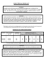
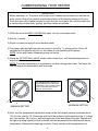
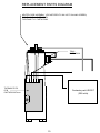
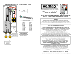
Eema X
THREE PHASE THERMOSTATIC
ELECTRIC INSTANTANEOUS WATER HEATER
MODELS: EX360T24T – EX480T24T
(208 volts only)
INSTALLATION GUIDE AND OWNERS MANUAL
WARNING
BEFORE ATTEMPTING INSTALLATION OF THIS UNIT OR MAKING ANY ADJUSTMENTS
TO THE UNIT ALWAYS BE SURE MAIN CIRCUIT BREAKER IS OFF TO PREVENT DANGER
OF SERIOUS ELECTRIC SHOCK.
INSTALLER/ CONSUMER RESPONSIBILITIES
PLEASE TAKE THE TIME TO READ NOT ONLY THIS MANUAL BUT ALSO THE
WARRANTY CARD ENCLOSED. WARRANTY OF THIS HEATER WILL DEPEND ON PROPER
INSTALLATION, OPERATION, AND REQUIRED MAINTENANCE. THE WARRANTY SHALL BE
VOID IF THE DESIGN ORSTRUCTURE OF THE WATER HEATER HAS BEEN ALTERED IN
ANY WAY WHATSOEVER. THE MANUFACTURER OF THIS WATER HEATER WILL NOT BE
LIABLE FOR ANY DAMAGES BECAUSE OF FAILURE TO COMPLY WITH THE INSTALLATION
AND OPERATING INSTRUCTIONS OUTLINED ON THE FOLLOWING PAGES.
IF YOU REQUIRE ANY HELP OR HAVE ANY QUESTIONS RELATING TO THE
INSTALLATION OR PERFORMANCE OF THIS HEATER, PLEASE CALL OUR TECHNICAL
SERVICE DEPARTMENT TOLL-FREE:
1-800-543-6163
HAVE THE INFORMATION LISTED BELOW BEFORE BEFORE CALLING.
MODEL :
ELEMENT RESISTANCE:
OHMS
SERIAL NO :
SWITCH ON FLOW RATE:
GPM
INSTALLATION DATE :
OPERATING TEMPERATURE
MIN:
MAX:
Eemax Inc., 353 Christian Street, Oxford, CT 06478
1
GENERAL
The Eemax “Three Phase Thermostatic” water heater is specifically designed to take in
cold or pre-heated water and heat it to temperatures suitable for commercial washing,
sluicing or processing up to a maximum temperature of 180 F (82 deg. C). To obtain
optimum performance and energy savings, the unit should be located as near as possible
to the point of use. The unit must only be installed in a vertical position with the inlet
and outlet at the bottom. The power is activated by individual electronic flow switches located
in each of the six heating modules. These will be damaged by excessive heat, do not solder
any pipes that are in contact with the heater.
Also ensure pipes are clear of installation debris before fitting the heater, otherwise the flow
switches could jam in the “on” position. The unit must be connected to its own individual electric
circuit protected by a suitably rated three pole breaker. The maximum voltage which can be
applied across any heating module is 208 volts.
WARNING
Improper installation, adjustment, alteration, service or maintenance can cause DEATH,
SERIOUS BODILY INJURY OR PROPERTY DAMAGE. Refer to this manual for
assistance or consult the local electric utility for further information.
The unit is supplied with 1” NPT pipe connections. Under no circumstances use a blow
torch on pipe which is connected to the heater (serious damage to the electronic flow
switch will result). Carefully use Teflon tape, ensuring no debris enter the heater. Do not
use pipe dope.
WARNING
Failure to ground the system may result in death or serious injury.
2
MOUNTING THE UNIT
1) The unit should be mounted as close to the point of use as possible.
2) This unit must only be mounted in the vertical position with the water fittings located at the
bottom of the unit. Mounting other than in the vertical position WILL cause element burn out.
3) The cold water inlet is on the right hand side and the hot water outlet is on the left hand side.
Under NO circumstances can these be reversed.
4) Leave a minimum of 8” above the unit for easy replacement of the elements.
5) The heater should be fixed to the wall using all six mounting holes of the backplate. Unit
weight is approximately 50 lbs. Use an appropriate fastener for this weight. For the unit to be
mounted against hollow walls, suggest using steel wall anchors, with the correct grip range
and #6-32 screw size minimum.
6) The unit should be installed in the plumbing system in such a way that there is no tendency
for the unit to be starved of water: for example: by an excessive draw-off of cold water just
before the unit. Also do not fit an unrestricted hot water draw-off point below the heater as
this will tend to empty the heater by siphoning.
Hazardous Locations - Nonincendive Type Installation
1) The unit is mounted in an approved NEMA4 Enclosure.
2) Non-incindive for Class I, Division 2, Groups A, B, C&D. Temperature class: T5 (212 °F)
3) As to installation, refer to the National Electrical Code and NFPA 70. For locations C1, Div.2
refer to section 501-4 (wiring methods) and 501-10 (utilization equipment) respectively.
Note: If ignition atmosphere is <T5 class, or if other classifications are required, another method of
compliance would be “Purged and Pressurized”. This is the process of supplying an enclosure
with a protective gas at a sufficient flow and positive pressure to reduce the concentration of
any flammable gas or vapor initially present to an acceptable level. For further information, see
ANSI/NFPA 496-1998, Purged and Pressurized Enclosures for Electrical Equipment.
3
PLUMBING HOOKUP
1) The unit is supplied with NPT fittings, USE THESE; DO NOT USE PIPE DOPE AND DO
NOT SOLDER PIPE TO THE INLET OR OUTLET.
2) Take care to ensure that the pipes are correctly aligned with the inlet and outlet bosses in
order to avoid excessive stress on the heater manifold.
NOTE: When soldering pipe joints remove heater from the wall. Serious damage can occur
if any soldering is done while pipes are connected to the heater.
Run water through the supply pipe to remove all debris from the pipe before connecting the
heater. Failure to do so could cause damage to the flow switch.
3) Install isolating valves (full flow ball valve type) on both inlet and outlet pipes. This allows
unit to be isolated for maintenance purposes. (see Fig. 1)
4) When all plumbing is complete, fully check the system for water leaks at all plumbing
connections. If leak is present take corrective action. Fully open both inlet and outlet
ball valves. Run all hot water outlets fed by this heater one at a time for a minute or two
until the water flow is continuous, free from ”gulping” and from all visible air pockets.
Hot outlet
1” NPT
fitting
DO NOT
SOLDER
Cold inlet
1” NPT
fitting
DO NOT
SOLDER
7“
NOTE
ALL MOUNTING AND PLUMBING MUST BE COMPLETE BEFORE YOU PROCEED
WITH ELECTRICAL HOOK-UP.
TEST THE INSTALLATION FOR LEAKS BEFORE CONNECTING THE
ELECTRICAL SUPPLY.
4
ELECTRICAL HOOK-UP
WARNING
HAZARD OF ELECTRICAL SHOCK! BEFORE BEGINNING ANY WORK ON THE
INSTALLATION, MAKE SURE THE ELECTRICAL SUPPLY TO THE HEATER IS TURNED
“OFF”. FAILURE TO DO THIS COULD RESULT IN DEATH, SERIOUS BODILY INJURY,
OR PROPERTY DAMAGE.
WARNING
WATER HEATERS EQUIPPED FOR ONE VOLTAGE ONLY: CHECK THE RATING PLATE
ON THE FRONT OF THE UNIT. DO NOT USE THIS WATER HEATER WITH ANY VOLTAGE
OTHER THAN THE ONE SHOWN ON THE MODEL RATING PLATE. FAILURE TO DO SO
CAN RESULT IN DEATH, SERIOUS BODILY INJURY, OR PROPERTY DAMAGE. IF YOU
HAVE ANY QUESTIONS OR DOUBTS CONSULT YOUR ELECTRIC COMPANY.
This heater must have its own independent circuit using four wires; three live and one ground,
of the appropriate rating protected by the correctly rated three pole breaker
RATINGS OF “EX” THREE PHASE MODELS
MODEL
EX 480
EX 360
MAX. OUTPUT
@ 208V
48 KW
36 KW
CURRENT
PER PHASE
4.0gpm
133
100
82
61
TEMPERATURE RISE (F)
5.0gpm 6.0gpm 7.5gpm 10.0gpm 12.5gpm
66
49
55
41
44
33
33
25
26
20
THIS UNIT MUST NOT BE CONNECTED IN STAR CONFIGURATION
WARNING
FAILURE TO GROUND THE SYSTEM MAY RESULT IN DEATH OR SERIOUS INJURY
IMPORTANT
BEFORE SWITCHING “ON” THE POWER AT THE MAIN CIRCUIT BREAKER PANEL MAKE
SURE THAT THE HOT WATER CIRCUIT IS FREE OF AIR POCKETS OR PREMATURE
FAILURE OF THE ELEMENT WILL OCCUR. TO DO THIS OPEN ALL HOT WATER OUTLETS
ONE AT A TIME FOR A MINUTE OR TWO UNTIL THE WATER FLOW IS CONTINUOUS AND
FREE FROM “GULPING” AND FROM VISIBLE AIR POCKETS.
5
COMMISSIONING YOUR HEATER
IMPORTANT
Before switching “on” the power at the main circuit breaker panel make sure that the hot
water circuit is free of air pockets or premature failure of the heating element will occur.
To do this open all hot water faucets one at a time for a minute or two until the water flow
is continuous and free from “gulping” and from visible air pockets.
1) With inlet and outlet BALL VALVES fully open, turn on a hot water outlet.
2) Run for 1 minute.
3) Switch on electric supply at circuit breaker panel.
4) The power indicator lights should now come on (see Fig. 1), pulsing at first. Allow 40
seconds for the lights to stay full on, the heater is now operating at full power.
NOTE: At this point water temperature may not be hot.
5) Using the OUTLET BALL VALVE slowly reduce water flow until desired temperature is
achieved at hot water outlet.
NOTE: The water temperature is regulated by the flow through the heater. The lower the
flow the higher the temperature and vice versa.
THE TEMPERATURE CONTROLLING
POTENTIOMETER IS A PRECISION
COMPONENT. ADJUST GENTLY AND
DO NOT TURN BEYOND THE MIN.
AND MAX. STOP POINTS
MAXIMUM SETTING
MINIMUM SETTING
6) Now turn the temperature adjustment screw on the first module counter clockwise about
1/8 of a turn, wait for 10-15 seconds and see if the indicator light begins to pulse. If it does
not, turn another 1/8 of a turn, wait and again see if the lamp begins to pulse. Repeat until
the light is pulsing regularly which indicates that the temperature has stabilized at the set
temperature. Repeat with remaining modules. Check that the outlet temperature is at
6
the desired temperature and that all six elements are pulsing equally. The thermostats
are now set and the water temperature will always be the same when the lights are pulsing.
7) Check performance of flow switch by opening and closing the faucet of the outlet valve a
few times.
THE POWER INDICATOR LIGHT SHOULD ONLY BE ON WHEN WATER IS FLOWING
THROUGH THE UNIT. For expected temperature rise at various rates of flow see chart
8) It is possible that drawing off cold water at comparatively high rates of flow elsewhere in
the building at the same time that the heater is working, could cause premature element
failure. Care should be taken not to starve the unit of cold water. To prevent this from
happening, open fully the main valve on the cold supply to the building and throttle back
the control valves to the other cold water outlets.
9) Do not operate heater if there is a possibility that the water in the heater is frozen. Element
module housing failure could occur.
7
TROUBLESHOOTING
SYMPTOM: NO HEAT INDICATOR LIGHT OFF
1)ELECTRIC SUPPLY IS OFF
Turn on the main circuit breaker.
2)NO OR LOW WATER FLOW
Ensure that the minimum flow rate to switch on your heater is met,
for this figure refer to the front cover of this manual.
Also check that the inlet filter screen is clear from any debris.
3)WATER CONNECTIONS ARE REVERSED
Cold water inlet = right side, hot water outlet = left side.
4)ELEMENT BURNED OUT
TURN OFF THE MAIN BREAKER!
Using an ohmmeter test the resistance of the heating element
across the two threaded termination rods on top of the element.
See the front cover of this manual for the correct value.
If the resistance is much greater than the correct value, call
your supplier for a replacement element.
SYMPTOM: NO HEAT OR LOW TEMPERATURE WITH
INDICATOR LIGHT ON
1)WATER FLOW TOO HIGH
Reduce the water flow by using an outlet ball valve. See page 5
for temperature rise at various flow rates.
2)INCORRECT POWER SUPPLY
Make sure that the unit is connected to the voltage supply specified
on the rating label on the the front cover of the unit and no other.
3)ELEMENT BURNED OUT
TURN OFF THE MAIN BREAKER!
Repeat the steps from paragraph 4 above.
4)THERMOSTAT ADJUSTMENT SCREW NOT TURNED UP
Turn the thermostat adjustment screw clockwise in small
increments until the indicator light remains on. Take care not to
force the screw past it’s stop position.
8
REQUIRED MAINTENANCE PROCEDURE
To Be Performed by Qualified Personnel
MONTHLY CHECKS
M1) Ensure main circuit breaker is on.
M2) Open outlet valve(s) to run water thru unit. Ensure that the
minimum flow rate to switch on your heater is met, for this
figure refer to the front cover of this manual.
M3) Check outlet temperature for desired setting.
QUARTERLY CHECKS
Q1) Turn off main circuit breaker.
Q2) Remove front cover from heater.
Q3) Inspection of heater bodies and distribution manifold for
water leaks.
Q4) Inspection of fuses (50 amp each)
Q5) Inspection of 6 heater elements (see page 10 for element ohms)
Q5) Inspection of coarse inlet filter screen is clear from any debris.
Q6) Turn on main circuit breaker (note: unit has live electrical)
Q7) Carefully perform steps M1 thru M3 with cover removed, observe
each module for an indicator light.
Q8) Turn off circuit breaker
Q9) Install front cover, then turn on main circuit breaker.
9
REPLACEMENT PARTS DIAGRAM
HEATER CORE ASSEMBLY (PLEASE SPECIFY 208 VOLTS ON ANY ORDERS)
FOR EX360 T12 PART# EX720
FOR EX480 T12 PART# EX540
TRIAC
PART# EX18
THERMOSTATIC
PCB
PART# EX100F/cont
Contactor part # EX257
(208 volts)
10