1
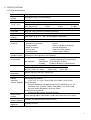
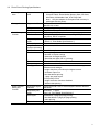
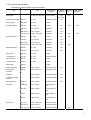
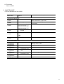
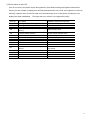
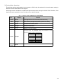
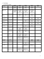
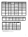
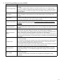
S530D
SERVICE
MANUAL
Canon
1.
2.
PRODUCT OUTLINE.....................................................................................................................................3
SPECIFICATIONS .........................................................................................................................................4
2-1 Printer Specifications...................................................................................................................................4
2-2 Photo Direct Printing Specifications ..........................................................................................................5
2-3 Print Head Specifications ............................................................................................................................6
2-4 Printer / Scanner Drivers .............................................................................................................................6
2-5 Optional Device (TFT Image Viewer) Specifications ....................................................................................6
2-6 Print Media Specifications ...........................................................................................................................7
2-7 Print Area ....................................................................................................................................................8
3. MAINTENANCE.............................................................................................................................................8
3-1 Error Indications of the S530D.....................................................................................................................8
3-2 Error Status on the LCD...............................................................................................................................9
3-3 Service Mode Operations..........................................................................................................................10
4. PRINT MODE............................................................................................................................................... 11
4-1 Normal Print Mode ....................................................................................................................................11
4-2 Borderless Mode.......................................................................................................................................12
4-3 Reversible Mode .......................................................................................................................................12
4-4 Card Direct Print........................................................................................................................................12
4-5 Digital Camera Direct Print.......................................................................................................................12
5. DIRECT PRINTING DIFFERENCES FROM S830D.....................................................................................13
6. FUNCTION OF DIRECT PRINT...................................................................................................................14
6.1 Host PC Memory Card Access Function with the Memory Card Startup Utility...........................................14
6.2 Arrangement of image files........................................................................................................................15
6.3 Data access...............................................................................................................................................15
6.4 Card slot attribute......................................................................................................................................16
6.5 Memory Card Direct Printing Function.......................................................................................................16
6.6 Digital Camera Direct Printing Function .....................................................................................................18
6.7 Exclusive Processes..................................................................................................................................20
6.8 Operations in the Operation Panel.............................................................................................................21
6.9 Mode Displays in Operation Panel.............................................................................................................22
6.10 Maintenance Display and Operation........................................................................................................24
6.11 Card Slot-related Operation and Display..................................................................................................25
6.12 DPOF Settings in the Memory Card Direct Printing Function ...................................................................27
6.13 Print Layout (Details)...............................................................................................................................28
6.14 Date print specifications...........................................................................................................................32
6.15 Photo number printing in Memory Card Direct Printing.............................................................................34
6.16 Direct Printing Functions with Digital Camera Connected to the S530D...................................................35
6.17 OPTION IMAGE VIEWER CV-100...........................................................................................................37
6.18 Operation Panel and CV-100 Display ......................................................................................................38
6.19 CV-100 Display........................................................................................................................................39
6.20 Maintenance............................................................................................................................................43
6.21 Trimming Function...................................................................................................................................43
2
1. PRODUCT OUTLINE
The S530D is a photo printer incorporating the S830D functionality of direct printing from digital cameras,
and the same engine as the S520, capable of high quality and high speed printing.
3
2. SPECIFICATIONS
2-1 Printer Specifications
Type
Paper feeding
method
Resolution
Throughput
(Target value)
Printing direction
Print width
Interface
ASF stacking
capacity
Paper weight
Detection
functions
Acoustic noise
(standard mode)
Environmental
requirements
Power supply
External
dimensions
Weight
Related
standards
(Printer, Adapter)
Serial number
location
Remaining ink
amount detection
Print head
alignment
Desktop serial color bubble jet printer
Auto sheet feed (no manual feeding)
2,400 dpi x 1,200 dpi (Max.)
Draft
14 ppm
9 ppm
Standard
12 ppm
8 ppm
Black (New Black)
Color (New Color)
Bidirectional, uni-directional
Max. 203.2 mm (216 mm in borderless printing)
USB FULL SPEED
High
1.1 ppm
0.6 ppm
Plain paper (75 g / m2): Max. 10 mm (Approx. 100 sheets)
64 to 105 g / m2
- Cover open
- Presence of print head
- Distinction of print head
- Ink out
- Printing position
- Paper out (Paper end sensor)
- Waste ink amount
- Internal temperature
- Pick-up roller
- Paper feed roller position
- Carriage position
- Head-to-paper distance
Sound pressure level* : 46 dB (A)
*conforms to sound pressure level ISO9296
During operation Temperature 5C to 35C (41F to 95F)
Humidity
10%RH to 90%RH (no condensation)
Non operation
Temperature 0C to 40C(32F to 104F)
Humidity
5%RH to 95%RH (no condensation)
Input voltage
Frequency Power consumption Standby
Approx.36W
Approx.6W
AC 100 to 127 V 50 / 60 Hz
Approx.36W
Approx.6W
AC 220 to 240 V 50 / 60 Hz
Approx. 430 (W) x 301 (D) x 188 (H) mm
Approx. 5.7 kg, not including print head and optional device
Electromagnetic radiance:
VCCI, FCC, IC, C-tick, Taiwan EMC, Korea EMC, CCIB, CCEE
Electrical safety:
Electrical Appliance and Material Control Law (DENTORI), UL, Cul,
CB Report, GS, CE Mark, FIMKO, CCIB (EMC), AS, CCEE, PSB,
Electrical Safety Regulations of Korea, SASO
Environmental regulations:
Energy Star, Blue Angel, Environment label
On the carriage ribbon cable holder (visible when the front cover is open).
Available (by optical detection and dot count)
Available (6 types)
4
2-2 Photo Direct Printing Specifications
Memory card
drive
Storage function
Card direct print
function
Digital camera
direct print
function
Supported memory PCMCIA Type II compliant
card
Compact Flash, Smart Media, Memory Stick, SD Card,
Microdrive, Multimedia Card, ATA Flash Card
Note: Only the adaptor for Compact Flash memory is
packaged with the printer.
Supported OS
Windows Me / 98 / 2000 / XP
Mac OS 8.6 or later
Utility
Storage utility packaged with printer
Function
Read / Write
Operation panel
LCD, 8 keys, 5 LEDs, no buzzer
File format
JPEG (DCF, CIFF, Exif 2.1 or later, JFIF), TIFF (Exif
compliant), DPOF compliant
7 types
Supported print
paper
(See 2-6, “Print Media Specifications.”)
Print quality
3 levels
Image correction
APP2, Vivid, sYCC
function (trimming)
DPOF version
Ver. 1.00 compliant
Function
- Index printing
- Number of copies settings
- Selection of images to print
- Specified text (date, file no.) printing
Resolution
Max. 2,400 x 1,200 dpi
Date printing
Available
Throughput
Approx. 1 minute and 50 seconds, with the following
conditions and settings:
- Image data from a 3 million pixel digital camera
- A4 Photo Paper Pro
- Non-borderless printing
- 1 page per page layout
- Print quality level 2
- Image correction functions disabled
- Without date printing
Supported digital
Power Shot S40 / S30, or Canon digital cameras released
cameras
thereafter
Supported print
Overseas: 5 types
paper
(See 2-6, “Print Media Specifications.”)
Print layout
- Borderless 1-page per page printing
- Non-borderless 1-page per page printing
- Index printing
Resolution
Max. 2,400 x 1,200 dpi
5
2-3 Print Head Specifications
Print heads
Type
Replaceable ink tank type, single head for black and color (YMC) ink tanks
Print head
BK:
320 nozzles in 2 vertical lines
Color: 256 nozzles in 2 vertical lines per color
Ink color
Pigment-based black, Dye-based cyan, magenta, yellow
Ink tank
BCI-3eBK, BCI-3eC, BCI-3eM, BCI-3eY
Weight (Net)
Print head, 71g: BK, 32g: C, M, Y, 11g
Supply method
As a service part (not including ink tanks) with part number QY9-0034-000
2-4 Printer / Scanner Drivers
Printer driver:
Windows 98 / 98 S. E. / Millennium
Windows 2000
Windows XP
Macintosh (OS 8.6 and later)
Scanner driver:
The S530D does not support a scanner driver.
2-5 Optional Device (TFT Image Viewer) Specifications
LCD
1.5 low-temperature polysilicon TFT, 11.8 million pixels
- Total number of dots:
494 (horizontal) x 242 (vertical) = 119,548 dots
- Number of displayed dots: 480 (horizontal) x 240 (vertical) = 115,200 dots
Effective display area
31.115 (horizontal) x 30.360 (vertical) mm
Dot pitch
0.0635 (horizontal) x 0.09225 (vertical) mm
Color arrangement
RGB delta
Backlight
LED backlight
External dimensions
90 (W) x 50 (D) x 91 (H) mm, not including projection
Weight
TBD
Input voltage
DC 27 V, to be supplied from the printer
6
2-6 Print Media Specifications
The following types of paper are recommended:
Type
ASF stacking
capacity
Size
Borderless Card direct Digital camera
direct print
printing print
Plain paper
A4, B5, A5, LTR, LGL 10 mm or less
Yes
(A4, LTR)
High resolution paper HR-101
A4, LTR
80 sheets or less
Glossy paper
GP-301N
A4, LTR
1 sheet
Pro Photo paper
PR-101
A4, LTR
1 sheet
Yes
PR-101 L
89 x 127 mm
20 sheets
Yes
PR-101 2L
127 x 178 mm
20 sheets
Yes
PR-101 4 x 6 101.6 x 152.4 mm
20 sheets
PP-101
A4, LTR
PP-101 L
PP-101 2L
*1
Yes
Yes
Yes
Yes
Yes
Yes
Yes
1 sheet
Yes
Yes
89 x 127 mm
20 sheets
Yes
127 x 178 mm
20 sheets
Yes
PP-101 4 x 6 101.6 x 152.4 mm
20 sheets
Yes
MP-101
A4, LTR
10 sheets
Yes
MP-101 L
89 x 127 mm
20 sheets
Yes
Glossy film
HG-201
A4, LTR
1 sheet
Transparency
CF-102
A4, LTR
30 sheets or less
Banner paper
BP-101
A4, LTR
1 sheet
T-shirt transfer
TR-201
A4, LTR
1 sheet
Mouse pad
MK-101
-----
1 sheet
Glossy postcard
KH-201
148 x 100 mm
20 sheets or less
Glossy photo
postcard
FM-101
119 x 215.9 mm
20 sheets or less
Postcard
-----
148 x 100 mm
40 sheets or less
Yes
Postcard for inkjet
printers
-----
148 x 100 mm
40 sheets or less
Yes
Photo postcard
PH-101
148 x 100 mm
20 sheets or less
Yes
Envelope
COM #10
241 x 106 mm
10 envelopes or
less
DL-size
220 x 110 mm
10 envelopes or
less
Size 4
235 x 105 mm
10 envelopes or
less
Size 6
190 x 98 mm
10 envelopes or
less
PC-101 L
101.6 x 190.5 mm
20 sheets or less
PC-101 2L
210 x 183 mm
10 sheets or less
Photo Paper Plus
Matt Photo Paper
Photo card
PC-101 4 x 6 101.6 x 172 mm
20 sheets or less
Yes
Yes
Yes
*1: Only A4 in Japan, both A4 and LTR overseas
7
2-7 Print Area
Same as S520
3. MAINTENANCE
3-1 Error Indications of the S530D
Indicator
Blink Count
Error Status
Code*1
User-Recoverable Errors
Orange
1000 Paper feed error
2 blinks
Orange
1300 Paper jam error
3 blinks
Orange
1601 No-ink error(Bk)
4 blinks
1611 No-ink error(Y)
1612 No-ink error(M)
1613 No-ink error(C)
Orange
1401 BJ cartridge not
6 blinks
installed
Orange
7 blinks
Orange
8 blinks
1402 Cartridge error
1403
1405
1485
1700 Waste-ink warning
User-Unresolvable Errors
Orange/green
5100 CR error
2 toggle blinks
Orange/green
5C00 Purge sensor error
4 toggle blinks
Orange/green
5400 Abnormal internal
6 toggle blinks
temperature error
Orange/green
5B00 Waste ink full
7 toggle blinks
error
Orange/green
5200 Abnormal head
8 toggle blinks
temperature error
Orange/green
6800 EEPROM error
9 toggle blinks
Orange Light
--- RAM error
Probable Cause and Faulty Parts
Paper feed section, Sheet feeder unit,
Paper-end sensor, Logic board
Paper feed section, Paper-end sensor,
Logic board
Ink tank
Print head, Carriage unit
Print head, Logic board
Waste ink absorber, Logic board
Encorder film, carriage unit, Logic board,
Carriage ribbon cable
Purge unit, Logic board
Logic board
Ink absorber, Logic board
Print head, Logic board
Logic board
Logic board
8
3-2 Error status on the LCD
If an error occurs in the printer engine during Memory Card Direct Printing and Digital Camera Direct
Printing, an error number is displayed at the Required Sheets line of the LCD. As multiple errors such as
warnings, operator calls, and service calls, may simultaneously occur in the printer, priorities for error
display have been established. The larger the error number is, the higher the priority.
Error No.
001
002
101
102
103
201
202
301
302
401
402
611
612
802
803
809
Error status
Warning that printer is being used
Warning that printer is not ready
Ink low warning
Paper selection lever incorrect position
warning
Ink low warning + Paper selection lever
incorrect position warning
Ink out error
Waste ink warning
Paper out error
Paper jam error
Cover open error
No head installation error
Communication time error with digital
camera
Probable Cause and Faulty Parts
Non-supported digital camera error
Degital camera
Show the printe error status
Logic board
Logic board, I/F cable
Printer service call error
Printer errors
Other errors
Ink tank
Paper selection lever
Ink tank, Paper selection lever
Ink tank
Ink absorber, Logic board
Sheet Feeder Unit
Close the front cover
Print head, Logic board
Cable connect to the DSC, Sub board,
Logic board
9
3-3 Service Mode Operations
Though the service mode opration is the same as S520, only the method of the market area setting is
defferent from the S520.Refer to the figure1.
All the logic boards available as a replacement part contain printer settings for the BJ S530. Therefore, if the
logic board was re plased, be sure to set the correct printer settings.
Fig1:Functions of the S530D Service mode S530D
Press
Indicator
Function
Power off (Even if there is no print head mounted,the
carriadge will return to the home position and lock.)
0 times
Green
1 time
Orange
Service/factory test printout(Including ink sensor check)
2 times
Green
EEPROM information printout
3 times
Orange
EEPROM initialization
4 times
Green
5 times
Orange
More than
6 times
Clears the waste-ink counter
Waste-ink counter settings
After press the POWER button, reaching this service
function. Press the RESUME button the number of times
specified below to set the destination.
Setting
0 times
1 time
2 times
3 times
4 times
5 times
BJ S530
BJ S530
S530D
BJ 535PD
Green
10
4. Print Mode
4-1 Normal Print Mode
Paper type
Normal Paper
Bk
Normal Paper
Color
High Resolution
Paper
(HR-101)
No. of passes
Bk
Resolution (dpi)
No. of passes
Bk
Resolution (dpi)
No. of passes
Bk
Resolution (dpi)
Quality
Setting5
1 pass
PigBK
600x600
Quality
Setting4
1 pass
PigBK
600x600
Quality
Setting3
1 pass
PigBK
600x600
Quality
Setting2
4 passes
PigBK
600x600
1 pass(Bk)
1 pass(Color)
PigBK
600x600
1 pass (Bk)
2 pass (Color)
PigBK
BK,Y:600x600
C,M:1200x600
1 pass (Bk)
4 pass (Color)
PigBK
BK,Y:600x600
C,M:1200x600
4 pass (Bk)
4 pass (Color)
PigBK
BK:600x600
C,M,Y:1200x1200
2 pass
YMC
C,M:1200x600
4 pass
6 pass
YMC
YMC
C,M,Y:1200x1200 C,M,Y:1200x1200
Pro Photo Paper No. of passes
(PR-101/PC-101/ Bk
Resolution (dpi)
PH-101)
4 pass
YMC
C,M,Y:1200x1200
No. of passes
Glossy Paper
(GP-301/FM-101/ Bk
Resolution (dpi)
KH-201)
4 pass
6 pass
YMC
YMC
C,M,Y:1200x1200 C,M,Y:1200x1200
Photo Paper Plus No. of passes
Bk
(PP-101)
Resolution (dpi)
4 pass
YMC
C,M,Y:1200x1200
Matt Photo Paper No. of passes
Bk
(MP-101)
Resolution (dpi)
Inkjet Post Card No. of passes
Direction
Bk
Resolution (dpi)
No. of passes
Bk
Resolution (dpi)
4 pass
6 pass
YMC
YMC
C,M,Y:1200x1200 C,M,Y:1200x1200
4 pass
Unit-Direction
PigBK
600x600
4 pass
YMC
C,M,Y:1200x1200
Post Card
No. of passes
Direction
Bk
Resolution (dpi)
No. of passes
Bk
Resolution (dpi)
Glossy Film
(HG-201)
No. of passes
Bk
Resolution (dpi)
No. of passes
Bk
Resolution (dpi)
No. of passes
Bk
Resolution (dpi)
T-shirt Transfer
(TR-101)
OHP Film
(CF-102)
Envelope
No. of passes
Bk
Resolution (dpi)
2 pass
Unit-Direction
PigBK
600x600
2 pass
YMC
C,M:1200x600
Y:600x600
2 pass
Unit-Direction
PigBK
Bk:600x600
3 pass
PigBK+YMC
C,M:1200x600
Y:600x600
Quality
Setting1
6 pass
YMC
C,M,Y:1200x1200
12 pass
YMC
C,M,Y:1200x1200
6 pass
YMC
C,M,Y:1200x1200
4 pass
Unit-Direction
PigBK
BK:600x600
4 pass
PigBK+YMC
C,M,Y:1200x1200
4 pass
6 pass
YMC
YMC
C,M,Y:1200x1200 C,M,Y:1200x1200
6 pass
YMC
C,M,Y:1200x1200
4 pass
6 pass
PigBk+YMC
PigBk+YMC
C,M,Y:1200x1200 C,M,Y:1200x1200
3 pass
4 pass
PigBk+YMC
PigBk+YMC
BK:600x600
BK:600x600
C,M,Y:1200x1200 C,M,Y:1200x1200
11
4-2 Borderless Mode
Quality
Setting5
Media Type
Plain Paper
No. of passes
Bk
Resolution (dpi)
Pro Photo Paper No. of passes
(PR-101/PC-101/ Bk
Resolution (dpi)
PH-101)
No. of passes
Glossy Paper
( GP-301N/FM-10 Bk
Resolution (dpi)
1/KH-201)
Photo Paper Plus No. of passes
Bk
(pP-101)
Resolution (dpi)
Matt Photo Paper No. of passes
Bk
(MP-101)
Resolution (dpi)
Inkjet Post Card
No. of passes
Direction
Bk
Resolution (dpi)
Post Card
No. of passes
Direction
Bk
Resolution (dpi)
Quality
Setting4
2 pass
YMC
C,M,Y:1200x600
Quality
Setting3
Quality
Setting2
Quality
Setting1
4 pass
6 pass
YMC
YMC
C,M,Y:1200x1200 C,M,Y:1200x1200
4 pass
6 pass
12 pass
YMC
YMC
YMC
C,M,Y:1200x1200 C,M,Y:1200x1200 C,M,Y:1200x1200
4 pass
6 pass
YMC
YMC
C,M,Y:1200x1200 C,M,Y:1200x1200
4 pass
6 pass
YMC
YMC
C,M,Y:1200x1200 C,M,Y:1200x1200
2 pass
4 pass
Uni-Direction
YMC
PigBK
C,M,Y:1200x600
BK:600x600
C,M,Y:1200x1200
3 pass
4 pass
Uni-Direction
YMC
PigBK
C,M,Y:1200x600
BK:600x600
C,M,Y:1200x1200
4-3 Reverxible Mode
Quality
Setting5
1 pass (Bk)
1 pass (Color)
PigBK
600x600
Quality
Quality
Quality
Setting4
Setting3
Setting2
1 pass (Bk)
1 pass (Bk)
4 pass (Bk)
2 pass (Color)
4 pass (Color)
4 pass (Color)
PigBK
PigBK
PigBK
BK,Y:600x600 BK,Y:600x600
BK:600x600
C,M:1200x600 C,M:1200x600 C,M,Y:1200x1200
1 pass (Bk)
1 pass (Color)
PigBK
600x600
No. of passes
Bk
Resolution (dpi)
1 pass (Bk)
2 pass (Color)
PigBK
BK,Y:600x600
C,M:1200x600
4 pass
YMC
C,M,Y:1200x1200
6 pass
YMC
C,M,Y:1200x1200
No. of passes
Bk
Resolution (dpi)
Matt Photo Paper No. of passes
Bk
(MP-101)
Resolution (dpi)
4 pass
YMC
C,M,Y:1200x1200
4 pass
YMC
C,M,Y:1200x1200
6 pass
YMC
C,M,Y:1200x1200
6 pass
YMC
C,M,Y:1200x1200
Media Type
Plain Paper
No. of passes
Bk
Resolution (dpi)
Quality
Setting1
4-4 Card Direct Print
Media Type
Plain Paper
No. of passes
Bk
Resolution (dpi)
Pro Photo Paper
(PR-101/PC-101/
PH-101)
Photo Paper Plus
(PP-101)
4-5 Degital Camera Direct Print
Same as quality setting ** in the Card Direct Print.
12
5. Direct Printing Differences from S830D
Item
Order of image printing
Date printing
Index printing
Number of print sheets
Print head alignment
Digital camera direct
printing
Storage function
Trimming function
Viewer display
Differences
- Photo numbers are assigned in the order in which each photo was taken by a normal digital
camera.
- In a folder, a higher priority is placed on a file when the file name, not counting the file
extension, consists of 8 characters with the latter 4 being numeric, in compliance with the
DCF (Design rule for Camera File system). Files are sorted in ascending order of those 4
numeric figures.
- In printing of full screen without frame, the data is printed at the bottom right corner over the
image, regardless of print image size. (The date printing position moves relative to the
image.)
- In Index Printing, photo numbers are located almost at the center below each index image.
However, when DPOF Printing is selected, photo numbers and dates are located at the left
below each index image, in the same way with the S830D.
- Up to 9999 is displayed. If the number of sheets exceeds 9999, 9999 remains displayed.
- In direct printing from a memory card, the remaining number of sheets to be printed is
displayed. (If the remaining number of sheets to be printed exceeds 9999, 9999 is
displayed.)
- In Maintenance 4 (from the operation panel), the number of patterns to be checked is 7, and
the specifiable pattern numbers are from 4-01 to 4-07 accordingly, which differs from the
S830D.
- At print instruction from a digital camera, the POWER lamp starts flashing immediately. (If
the automatic print head cleaning is necessary, the cleaning starts immediately.)
- During Direct Printing from a digital camera, if printing is cancelled by pressing the Reset
button, all printing is cancelled, regardless of the number of copies settings.
However, if “Both (Index and Standard)” is selected for Print Type, and the Reset button is
pressed during Index Printing, only the Index Printing is cancelled, and Standard Printing is
performed.
- Exclusive controls when the storage function is set to the writable mode slightly differ from
those of the S830D.
- For several seconds after the storage function is set as a removable drive, direct access to
the memory card is prohibited due to the Photo Direct function. (During the period when
access is prohibited, the Print button lamp turns off once.)
- The exclusive control duration is 5 seconds, while that duration of the S830D is 3 seconds.
- During digital camera Direct Printing, writing is temporarily prohibited.
- New function, usable when optional Image Viewer is activated.
- Trimming is enabled when the mode is set to “Print All (all frames printing),” “Print One
(single frame printing),” or “Print Selected (specified frame printing),” and in borderless
printing.
- During Direct Printing from a memory card, the printer icon is displayed at the lower right
corner of the screen.
- In selecting an image with a cursor button, the hourglass icon may appear in some
instances.
13
6. Function of direct print
6.1 Host PC Memory Card Access Function with the Memory Card Startup Utility
6.1.1. Supported memory cards
Media types compatible with the host computer memory card access function and Memory Card Direct
Printing function are as follows:
Excluding the Flash ATA Card, the PCMCIA card (Type II) adapter is necessary. (A PCMCIA card [Type
II] [Compact Flash, CF2 supported] is packaged with the printer.)
- Compact Flash Card (CF1, CF2 [micro drive])
- Smart Media Card*
- Memory Stick*
- Flash ATA Card
- SD Card*
- Multimedia Card
* In the Memory Card Startup Utility, if Read/Write enabled mode is selected in “Change the drive’s
read/write attribute”, the use of memory cards where the write protection is set to read-only mode is
prohibited, and the operations are not assured.
Note: Cards incompatible with the PC Card ATA interface are not supported.
6.1.2. Mounting the drive
Windows:
When the S530D is connected by USB cable to a host computer with the Memory Card Startup Utility
installed, and the printer is powered on via the Power button, the card slot on the S530D is mounted in My
Computer as a removable drive.
Macintosh:
When the S530D is connected by USB cable to a host computer with the Memory Card Startup Utility
installed, and the printer is powered on via the Power button, and then a supported memory card is
inserted, the card slot on the S530D is mounted on the desktop as a removable drive.
- When the printer is connected to the computer, and is equipped with Image Viewer CV-100, it may take
approx. 10 seconds for the memory card start-up utility to run when a memory card is inserted. (When
the utility is set to “Auto-start an application when a card is inserted” on the Memory Card Startup Utility.
This phenomenon occurs due to the timing of an exclusive process with the CV-100.)
14
6.2 Arrangement of image files
Photo numbers are assigned in the order in which each photo was taken by a normal digital camera.
In a folder, a higher priority is placed on a file when the file name, not counting the file extension, consists of
8 characters with the latter 4 being numeric, in compliance with the DCF (Design rule for Camera File
system). Files are sorted in ascending order of those 4 numeric figures. Reproduction order on S830D and
the digital camera, and displaying order in ZoomBrowser may be different in some cases.
6.3 Data access
For mounted card slot of S530D, data access to the memory card is possible by performing the usual
file operations through the OS’s standard file control software (such as Explorer and Finder) and
general software applications. (The same operations as with standard removable drives are possible:
file reading, writing, deletion, media formatting, properties, etc.)
Note: In the Memory Card Startup Utility, when “Read Only” is selected in “Change the drive’s read/write
attribute”, it is not possible to write, delete, and format the data. When Read/Write enabled mode is
selected in “Change the drive’s read/write attribute”, the use of memory cards where the write protection is
set to the Read Only mode is prohibited.
- Memory card-supported file format: FAT16 only
(It may be possible to read/write with memory cards formatted using FAT32, NTFS, Macintosh, etc.,
however they are out of specifications.)
- Change of the number of files in the operation panel
When files have been added or deleted via the computer to the memory card, or the card has been
formatted, the number of files in the operation panel is not updated until the memory card is removed and
re-inserted.
- Update of the image displayed in the CV-100
With the CV-100 installed, when files have been added, deleted or updated from the computer to the
memory card, or the card has been formatted, the image displayed in the CV-100 is not updated until the
memory card is removed and re-inserted.
15
6.4 Card slot attribute
The card slot attributes can be changed by operating the Memory Card Startup Utility on the host computer.
Card Slot Attribute
Read only
Read/Write
State
To protect the data on the memory card, writing to the memory card inserted in
the card slot is prohibited. (Default setting)
Writing data to the memory card inserted in the card slot is allowed. (Use of
memory cards where the write protection is set to the Read Only mode is
prohibited.)
Note:
When the memory card is inserted to the printer, this attribute cannot be changed.
As the card slot attributes are stored in nonvolatile memory on the printer, attributes are kept even if the
printer is powered off by disconnecting the AC plug.
6.5 Memory Card Direct Printing Function
6.5.1. Print mode
“Print Selected” mode: To produce a blank frame
Once the applicable frame is set, set the next frame, and then change the applicable frame to “----“.
Ex. In a four-frame layout, to produce a blank frame in the second cell.
[Procedures on the operation panel in the Print Selected mode]
Order:
-01-
-02-
-03-
-02-
-04-
Specified photo number:
0001
0002
0003
----
0004
0001
0003
0004
6.5.2. Print Quality
The following quality levels can be selected. (O: Selectable)
A.Photo Paper Pro 4”X6”
B.Photo Paper Plus 4”X6”
C.Photo Paper Pro Perforated 4”X6”
D.Photo Paper Pro Letter
E.Photo Paper Pro A4
F.Plain Paper Letter
G.Plain Paper A4
Default setting is Quality 2.
Quality1
○
○
Quality2
○
○
○
○
○
○
○
Quality3
○
○
○
○
○
-
16
6.5.3. Supported image formats
Images in the following formats can be selected when using direct printing:
DCF, CIFF, EXIF (JPEG, Tiff), EXIF-R98, JFIF
JPEG image compatibility with S530D:
Format:
Baseline DCT
Pixel sampling:
4:2:2 and 4:1:1
Samples per pixel:
1 or 3
Maximum pixel size:
Approx. 4,800(H) x 3,600(V)
TIFF image compatibility with S530D:
Format:
Pixel composition:
RGB uncompressed or YCbCr uncompressed
8 bits each (for RGB and YCbCr)
Note: Non-supported images will not be printed, and the image skipped (not printed).
- When non-supported images are detected, “-E-“ (error) is displayed in “First/-Order-“ or “Last” of the
operation panel.
- Examples of non-supported files (note, some files can be printed):
TIFF (CMYK)
JPEG (CMYK)
TIFF (LZW compressed)
TIFF (JPEG compressed)
TIFF (ZIP compressed)
TIFF (over 5,000 pixels)
JPEG (over 5,000 pixels)
JPEG (Progressive)
JPEG (sampling ratio: 4:4:4)
TIFF (16 bit channel)
Note: Some files may be printed even out of the specifications.
- Certain images cannot be printed although they are within image format specifications.
For an unknown reason, when a memory card containing partially-damaged data (detected by a
software such like ScanDisk as a “Bad Block”) is inserted, and printing is attempted, there is a possibility
that printing as well as some key operations may not be possible. Rectifying the Bad Block in the
applicable image files through a file recovery software such like ScanDisk may correct the problem.
- Data in digital camera is processed on PhotoShop6.
When the original image file taken by the digital camera is processed on PhotoShop6, as PhotoShop6
leaves the thumbnail image in the original image file without deleting it, the following phenomena occur:
17
-> Pre-processed data is displayed in the CV-100 for a moment. (In the CV-100 specifications, if the
thumbnail image exists in the image file, the thumbnail image is displayed, and then full resolution
image is displayed.)
-> In print mode
(1) of index printing, as printing is conducted using the thumbnail image, processed
images are not printed. (In Print Quality
(2) and
(3), full resolution images are printed
even the thumbnail images exist, therefore processed images are printed.) In PhotoShop5.5, as the
thumbnail image is deleted after processing, the above phenomenon does not appear.
6.5.4. Supported file names
DOS Ver.6.2 compliance
Up to four hierarchies of files; ex. ¥aaa¥bbb¥ccc¥img.jpg, ¥aaa¥bbb¥ccc¥img.tif
- Length limitation: Up to 60 characters of name and directory name
- Extention: 3 characters (JPEG and TIFF do not support 4 characters.)
6.6 Digital Camera Direct Printing Function
6.6.1. Print mode
In Digital Camera Direct Printing, the following print modes are selectable.
Easy print:
Printing of images during reproduction of single frame or index.
Standard printing only.
DPOF print:
Printing with DPOF printing settings.
Standard and index printing can be set.
6.6.2. Media type
Media types that can be printed in the Digital Camera Direct Printing are as follows (Quality Mode is all
, and is the same as with the Memory Card Direct Printing):
When the language setting on the digital camera is not set to Japanese. (Default)
(Media types for overseas are all the same, however the panel display differs depending on the languages.
The following is the display of US English.)
Paper setting in digital camera operation panel
Card#1
Card#2
Card#3
LTR
A4
S530D
Photo PaPer Pro 4”X6”(PR-101 4”×6”)
Glossy Photo Plus 4”X6”(SP-101 4”×6”)
Photo PaPer Pro Perforated 4”X6”(PC-101 C、with perforation)
Photo PaPer Pro Letter(PR-101 LTR)
Photo PaPer Pro A4 (PR-101 A4)
When the language setting on the digital camera is set to Japanese
When the language setting on the digital camera is not set to Japanese, media types that can be printed
change.
Paper setting in digital camera operation panel
L
2L
Postcard
A4
Card
S530D
Professional Photo L (PR-101 L)
Professional Photo 2L (PR-101 2L)
Professional Photo postcard (PH-101)
Professional Photo A4 (PR-101)
Professional Photo card (PC-101 C with perforation)
18
6.6.3. Print layout
Print layout can be set to Border or Borderless in the digital camera operation panel.
Easy print:
- Borderless:
1 photo (2 photos in case of Card #3)
- Border:
1 photo (2 photos in case of Card #3)
DPOF print:
Standard:
- Borderless:
1 photo (2 photos in case of Card #3)
- Border:
1 photo (2 photos in case of Card #3)
Index Print:
- Same as with the Index mode of Memory Card Direct Printing.
6.6.4. Print quality
Not selectable by users
(Quality Mode is all
, and is the same as with the Memory Card Direct Printing)
6.6.5. Image correction function
Not selectable by users (Image correction is always off)
6.6.6. Maintenance
Maintenance operation of the S530D via the digital camera’s operation panel is not possible.
Maintenance operation is possible through the operation panel of the S530D printer even when connected
to the digital camera.
6.6.7. Print date
Dates can be printed by switching the date setting to “ON” on the digital camera’s operation panel.
Dates cannot be printed in index printing of DPOF print mode.
6.6.8. Copies
The number of prints can be specified in both Easy Print and DPOF Print modes via the digital camera’s
operation panel.
19
6.7 Exclusive Processes
6.7.1. Exclusive processes in Memory Card Direct Printing and Digital Camera Direct Printing
As it is impossible to simultaneously process Memory Card Direct Printing and Digital Camera Direct
Printing, the following actions are taken:
When the digital camera is connected via the digital camera connection cable:
Memory Card Direct Printing settings and operation are not possible except for the Maintenance mode.
Setting items are not displayed in the operation panel, and the print start key is invalid.
When direct printing from the memory card:
Digital Camera Direct Printing is impossible. (Setting in the digital camera is possible.) At the start of
print operations in the Digital Camera Direct Printing, an error is displayed in the digital camera.
6.7.2. Exclusive process in direct printing and printing from host computer
As it is impossible to simultaneously process the Memory Card Direct Printing, Digital Camera Direct
Printing and printing from the host computer, the following actions are taken:
When printing from the host computer:
Memory Card Direct Printing and Digital Camera Direct Printing are impossible. (Setting is possible.)
At the start of print operations, an error is displayed in the operation panel of the digital camera.
In Memory Card Direct Printing and Digital Camera Direct Printing:
Printing from the host computer is impossible. (Print setting on the host computer is possible.) At the
start of print operations from the host computer, an error is displayed in the host computer.
20
6.7.3. Exclusive processes in host computer memory card access and Memory Card Direct Printing
Writing of data from the host computer to the memory card, while reading of image data from the memory
card for direct printing is conducted as follows in order to avoid overwriting the image being printed in
Memory Card Direct Printing, via the host computer.
When direct printing from the memory card:
Writing data from the host computer to the memory card is not possible. (Reading of data is possible.)
An error is displayed in the host computer at the start of data writing operations.
When writing data from the host computer to the memory card*:
Direct printing from the memory card is not possible. Even if the print start key is pressed, printing will
not start.
*From the time the host computer sends writing commands until a fixed period of time after the last
writing command.
Note: In order to perform direct printing after writing data from the computer is completed, the memory
card must be removed, and reinserted.
6.8 Operations in the Operation Panel
6.8.1. Print button
When this button is pressed, Memory Card Direct Printing starts. An LED installed inside the button blinks
during printing. The button is also used to select setting values while in maintenance mode.
6.8.2. Cancel button
When this button is pressed during Memory Card Direct Printing, printing stops. The button is also used to
reset the Memory Card Direct Printing settings to the default of each mode. (The button is invalid when
pressed during printing from the host computer or Digital Camera Direct Printing.)
6.8.3. Cursor buttons
Pressing the vertical cursor buttons moves the cursor at both ends of the LCD.
Pressing the horizontal cursor buttons alters the setting values of each item.
For the photo number and the number of copies, the left button decreases the number, and the right button
increases the number.
21
6.9 Mode Displays in Operation Panel
6.9.1. No card insertion
Nothing is displayed in the LCD when the printer is powered on, and a valid memory card is not inserted, or
a digital camera is not connected.
Possible key operation under the mode:
Power button:
Powers off the printer.
Resume button:
Resets the printer. (same as with the S520)
Maintenance button:
Enters the maintenance mode.
Other buttons:
Invalid.
6.9.2. Index mode
The Print Index LED is turned when the Index mode is selected to perform index printing of photographs in
the memory card. The photo numbers for the starting (first) and finishing (last) images are selectable.
Layout and Optimize Image cannot be selected.
This mode is selected by default if the memory card has no DPOF settings, and no optional CV-100 is
connected.
6.9.3. All frame mode
The Print All LED is turned on when the All Frame mode is selected to print all photographs from the first to
the last photo numbers.
The starting (first) and finishing (last) photo numbers to be printed can be set.
6.9.4. Single frame mode
The Print One LED is turned on when the single frame mode is selected to print a specified single photo
number and the specified number of copies.
This mode is selected by default if the memory card has no DPOF settings, and the optional CV-100 is
connected.
6.9.5. Specified frame mode
The Print Selected LED is turned on when the specified frame mode is selected to perform printing by
specifying the printing order and applicable photo numbers.
6.9.6. DPOF mode
The DPOF LED is turned on when the DPOF mode is selected to perform printing according to the
DPOF-specified information on the memory card.
It is impossible to specify the photo numbers and date printing through the operation panel, as they are
dependent on the DPOF settings.
This mode is selected by default if the memory card has DPOF settings.
The mode cannot be selected if the memory card has no DPOF settings. (The mode is skipped even if the
mode button is pressed.)
22
6.9.7. Digital camera direct mode
The camera mark appears in the LCD when the digital camera is connected. (Even with the memory card
inserted, all displays other than the camera mark disappear.)
When a supported digital camera is connected with the digital camera connection cable, the printer enters
this mode by priority. (However, if Memory Card Direct Printing is being performed, the printer will not
enter this mode until printing has completed. In the maintenance mode, the printer does not enter the
digital camera direct mode until the printer exits the maintenance mode via the maintenance button.)
In the digital camera direct mode, the printer will not enter other print modes until the digital camera is
disconnected from the printer, even if the Mode button is pressed.
When the maintenance button is pressed, the printer will enter the maintenance mode if printing is not being
performed.
If an error occurs, the error is displayed in the Required Sheets line of the LCD.
In the digital camera direct mode, when print start is designated from the digital camera, Digital Camera
Direct Printing starts.
Possible key operation under the mode:
Power button:
Powers off the printer.
Resume button:
Resets the printer (same as with the S520).
Maintenance button:
Enters maintenance mode unless Digital Camera Direct Printing is being
performed.
Other buttons:
Invalid
6.9.8. Maintenance mode
The maintenance icon appears in the Required Sheets line of the LCD when the maintenance mode is
selected to maintain the S530D and optional CV-100.
This mode is selected by pressing the maintenance button, except during Memory Card Direct Printing and
Digital Camera Direct Printing.
Possible key operation under the mode:
Power button:
Powers off the printer.
Resume button:
Resets the printer (same as with the S520).
Mode button:
invalid.
Print button:
Specifies and implements the maintenance selection items.
Resume/Cancel button: Resets the maintenance items to default.
Maintenance button:
Exits the maintenance mode.
23
6.9.9. Error display
Error number is displayed in the Required Sheets line of the LCD when errors occur in the S530D.
The display clears when the errors are recovered.
Note: Details of error displays are described in the following section.
Possible key operation under the mode:
Power button:
Powers off the printer.
Resume button:
Resets the printer (same as with the S520).
Mode button:
Invalid.
Print button:
Error-dependent.
Resume/Cancel button:
Error-dependent.
Maintenance button:
Invalid.
6.10 Maintenance Display and Operation
6.10.1. Maintenance list
Maintenance No.
1
2
3
4
5
6
Content of Maintenance
Nozzle check pattern printing
Head cleaning
Head refreshing
Head alignment
Optional CV-100 brightness adjustment* (selectable only when the CV-100 is
connected)
Optional CV-100 contrast adjustment* (selectable only when the CV-100 is connected)
*Available when a memory card containing data is inserted and while there is no active connection to a
powered on digital camera.
6.10.2. Entering the maintenance mode
Pressing the Maintenance button on the operation panel moves the printer to the maintenance mode.
The printer will not enter the mode while Memory Card Direct Printing and Digital Camera Direct Printing, or
when an error is displayed in the operation panel.
6.10.3. Implementing maintenance
Pressing the Print button in the maintenance mode executes the selected maintenance operation.
When the maintenance number is 0, the operation is invalid.
When the printer starts the maintenance, the step number showing the processing level of each
maintenance is displayed to the right of the maintenance number such as ‘1-01’.
During maintenance implementation, the left and right cursor keys cannot be switched to other maintenance
modes.
During each step implementation, if an error occurs in the printer engine, the operation panel enters the
error display mode.
24
6.11 Card Slot-related Operation and Display
6.11.1. Removing the memory card
Users can force the ejection of memory cards inserted in the card slot, by pressing the Eject button next to
the slot. However, in order to protect the data on the memory card, remove the card using any of the
following timings/methods:
- While the Access lamp is not lit, press the Eject button to remove the memory card.
- If the memory card is removed while the Access lamp is blinking or on, the data on the card is not assured.
- When the printer is not connected to a host computer, power off the printer with the Power button and after
the Access lamp is unlight, remove the memory card.
- Remove the memory card together with the adapter, not the memory card only.
- When the printer is connected to the host computer, from the host computer, select “Eject disk” to unlit the
Access lamp, and then remove the memory card.
(Turning off the printer makes it possible to turn off the Access lamp, however in this case, a warning
message of incorrect disk removal may be displayed in the connected host computer.)
When a Windows PC is used and the drive of the memory card is displayed in Explorer, close the window
prior to the removal of the memory card.
(If the window is not closed prior to the memory card removal, the following phenomenon will appear in the
host computer.)
WindowsMe/98:
A blue background screen appears. This can be recovered by following the
instructions in the display.
Windows2000/XP: A warning is displayed, and the ejection operation cannot be executed.
25
6.11.2. Power supply/cut to the memory card
1) Power supply to the memory card
When any of the following events occurs, the memory card detection process starts, and if an accessible
memory card is recognized, power supply to the memory card starts. (At the time that the Access lamp
is turned on.)
a. When a memory card is inserted into the card slot while the printer is on.
b. When the printer is powered on while a memory card is in the card slot.
c. When the USB bus is reset while the printer is on with a memory card in the card slot.
(When the host computer is already on, and is connected to the printer, or when the host computer,
connected by a USB cable to the printer, is restarted.)
2) Power cut to the memory card
When any of the following events occur, power supply to the memory card is cut. (At the time that the
Access lamp is turned off.)
a. When the printer is turned off by pressing the Power button.
However, power is supplied in the following instances even if the printer is not on,
- From the time that a memory card removable command is received from the host computer until a
removal permission command is received, or the USB cable is disconnected.
- From the time that a writing command is received from the host computer to the memory card until
writing is completed.
b. When the memory card is removed from the card slot by pressing the Eject Button.
c. When the following “Memory card removal command” is implemented on the connected host
computer.
6.11.3. Memory card removal command from the host computer
When the following operation is performed on the host computer, it is detected that the memory card
removal command has been implemented, and power supply to the memory card is cut.
Windows: Highlight the drive icon and right-click the mouse button to select “Remove”, or select “Eject
the memory card” from the Memory Card Startup Utility.
Macintosh: Discard the drive icon to the trash, select “Removal” from the “Special” menu, or select “Eject
the memory card” from the Memory Card Startup Utility.
6.11.4. Writing to the memory card from the host computer
When writing (addition, deleting or updating) is implemented, the print mode settings are returned to default.
26
6.12 DPOF Settings in the Memory Card Direct Printing Function
6.12.1. Supported DPOF functions
DPOF Ver. 1.0 is supported.
The following essential functions of the DPOF printer are supported.
- Standard printing
- No. of copies to be printed (1 page)
- Image format (CIFF, EXIF (JPEG), JFIF)
- Designation of images to be printed (relative path name)
The following optional functions to the DPOF printer are supported.
- Index printing
- No. of copies to be printed (2 pages or more)
- Image format (EXIF (TIFF))
- Printing of designated characters (dates, photo numbers)
If both dates and photo numbers are selected, one of the two will be printed.
Note: The CMT value indicating the comment and title of the image is not supported.
The following optional functions to the DPOF printer are not supported.
- Image format (FlashPix)
- Designation of paper types
- Trimming
- Rotation of images
6.12.2. Print specifications in DPOF print mode of Memory Card Direct Printing
Photo number designation:
Only photos that have been designated in the DPOF file are to be printed, and
designation is impossible from the operation panel.
Paper type:
The paper type can be selected from the operation panel.
Layout:
Images designated for Standard printing in the DPOF file are printed in the
designated order in the layout designated through the operation panel.
No. of copies to be printed:
The number cannot be designated from the operation panel, and the number
of copies that has been designated in the DPOF file is printed.
Image correction:
Automatic image correction can be designated from the operation panel.
Quality:
The print quality can be designated form the operation panel.
Date print:
Date print cannot be designated from the operation panel in the DPOF mode,
and printing is implemented by following the DPOF settings of the file. Date
formats are dependent on the digital camera.
(Note: When direct printing from a digital camera, even if specified in the
DPOF file, date printing will not be performed.)
27
6.13 Print Layout (Details)
6.13.1. Selectable layout in Memory Card Direct Printing (O: Applicable)
Media Type
A.Photo Paper Pro 4”X6”
All Frame / Single Frame / Specified Frame / DPOF Modes
Borderless 1Photo 2Photos 4Photos 8Photos 16Photos
B.Photo Paper Plus 4”X6”
Index mode
-
O
O
O
O
O
O
O (24 photos)
-
O*
-
-
-
-
O (24 photos)
C.Photo Paper Pro Perforated
4”X6”
D.Photo Paper Pro Letter
-
O
-
-
-
-
O (24 photos)
O
O
O
O
O
O
O (80 photos)
E.Photo Paper Pro A4
O
O
O
O
O
O
O (80 photos)
F.Plain Paper Letter
O
O
O
O
O
O
O (80 photos)
G.Plain Paper A4
O
O
O
O
O
O
O (80 photos)
*Cut the paper along perforation after printing to make borderless photo.
6.13.2. Selectable layout in Digital Camera Direct Printing
When the language setting on the digital camera is not set to Japanese.
(Media types for overseas are all the same, however the panel display differs depending on the languages.
The following is the display of US English.)
Media Type
Card#1(Photo PaPer Pro 4”X6”)
Card#2(Glossy Photo Cards Perforated 4”X6”)
Card#3(Photo PaPer Pro Perforated 4”X6”)
LTR(Photo PaPer Pro Letter)
A4(Photo PaPer Pro A4)
Standard
Borderless
O (1 photo)
O (1 photo)
O (1 photo)
O (1 photo)
O (1 photo)
Border
O (1 photo)
O (1 photo)
O (1 photo)
O (1 photo)
O (1 photo)
Index
―
O (24 photos)
O (24 photos)
O (24 photos)
O (80 photos)
O (80 photos)
When the language setting on the digital camera is set to Japanese
Standard
Media Type
L (Professional Photo L)
2L (Professional Photo 2L)
Postcard (Professional Photo postcard)
Card (Professional Photo card)
A4 (Professional Photo A4)
Borderless
O (1 photo)
O (1 photo)
O (1 photo)
O (2 photos)
O (1 photo)
Index
Border
O (1 photo)
O (1 photo)
O (1 photo)
O (2 photos)
O (1 photo)
O (15 photos)
O (35 photos)
O (24 photos)
O (12 photos)
O (80 photos)
6.13.3. Layout in Memory Card Direct Printing
Layout of multiple images is arranged as shown below.
- Images are arranged horizontally, from left to right, top to bottom.
1
2
3
4
5
1
2
3
4
5
6
7
8
9
10
11
12
13
14
15
16
- In All Frame printing and index printing modes, when the Start photo number is larger than the Last photo
number, printing is performed from the Last photo in reverse order.
- When the number of photos designated requires less space than the layout provides, nothing is printed in
the remaining spaces.
28
6.13.4. Layout and trimming
Trimming can be automatically performed. (Manual trimming is not possible.)
Memory Card Direct Printing (X: No trimming, O: Trimming)
Mode
Layout
Professional Photo Paper A4
Plain Paper A4
Photo Paper Pro Letter
Plain Paper Letter
Photo Paper Pro 4”X6”
Photo PaPer Pro Perforated 4”X6”
Glossy Photo Cards Perforated 4”X6”
Index
-
Borderless
X
O
X
All Frame / Single Frame / Specified Frame / DPOF
1 photo
2 photos
4 photos
8 photos
X
X
X
X
16 photos
X
O
Digital Camera Direct Printing: (X: No trimming, O: Trimming)
Print Designation
Border/Borderless
Professional Photo Paper A4
Professional Photo Paper Letter
Photo Paper Pro 4”X6”
Photo Paper Pro Perforated 4”X6”
Glossy Photo Cards Perforated 4”X6”
Index
-
Borderless
Standard
Border
X
O
X
29
6.13.5. Layout and image size
Processing in borderless printing
1) Rotate the image data by 90 degrees (if necessary) to align the long edges of the image with those of the
paper (or perforated lines).
2) Enlarge (or reduce) the image data in the same magnification of portrait and landscape so as to align
either the long or short edges of the image with those of the paper (or perforated lines), so that blank
space in the paper (inside the perforated line) is completely eliminated.
3) Any image data extending beyond the printing area will be cut off and not printed. (The discarded
image data will be equally divided between top and bottom, or left and right.)
Note: As printing of the image is performed to an area 5 mm larger than that of the paper size, the
perimeter of the image is further trimmed by a few millimeters.
30
6.13.6. Processing in printing in print area without image trimming
1) Rotate the image data by 90 degrees (if necessary) to align the long edge of the image data with those of
the paper (or perforated lines).
2) Enlarge (or reduce) the image data in the same magnification of portrait and landscape so as to align
either the long or short edges of the image with those of the print area (blue line), so that no image data is
discarded.
3) The area without any image data will be blank. (Empty areas will be equally divided between left and
right, or top and bottom.)
31
6.14 Date print specifications
6.14.1. Date print in Memory Card Direct Printing
1) Settings and data format
Printing in DPOF (Index and Standard) mode:
When date print is set to ON in the DPOF settings, the date is printed using the character strings in the
DPOF settings.
Printing in other modes:
When date print in the operation panel is set to ON, the date information in the file is printed in the
following order: Year (four digits). Month (two digits). and Date (two digits) (with date elements
separated by periods)
Ex. 1999.09.01
Index mode
2) Print location, color and size
Printing in Index mode:
Location:
Below the image (under the photo number)
Color:
Black
Size:
Fixed size
0001
1999.06.30
DPOF mode
Printing in DPOF (Index) mode:
Location:
Below the image
Color:
Black
Size:
Fixed size
1999.06.30
Printing in DPOF (Standard) and other modes:
Location:
Lower right, in the image (In the images where the ratio is other than 4:3, the date
may
be printed outside or partially overlapping the image.)
Color:
Orange
Size:
According to the layout.
Print sample1
Print sample2
1999.06.30
1999.06.30
32
6.14.2. Date print in Digital Camera Direct Printing
1) Settings and data format
In the digital camera, when date print is set to ON, the date will be printed using the character strings sent
by the digital camera. However, in the DPOF mode index printing using the digital camera, the date will
not be printed, regardless of the settings.
2) Print location, color and size
Printing in easy print and DPOF (Standard) modes:
Location:
Lower right, in the image (In images with aspect ratio other than 4:3, the date may be
printed outside or partially overlapping the image.)
Color:
Orange
Size:
According to the layout.
1999.06.30
Printing in DPOF (Index) mode:
Date will not be printed, even when set in the DPOF settings of the digital camera.
33
6.15 Photo number printing in Memory Card Direct Printing
6.15.1. Photo number printing in Memory Card Direct Printing
1) Data format
Printing in Index mode:
Photo number (4-digit number displayed on the operation panel) is printed. (Printed without exception)
Printing in DPOF (Index and Standard) mode:
When the file number print is set to ON in the DPOF settings, the file number character string set in the
DPOF settings is printed, as is. (However, when date print is selected, the file number will not be
printed.)
Printing in other modes:
The photo number will not be printed.
Index mode
Printing in Index mode:
Location:
Below the image (Above the date)
Color:
Black
Size:
Fixed size
Printing in DPOF (Index) mode:
0001
DPOF (Index) Mode
Location: Below the image
Color:
Black
Size:
Fixed size
102-0229
Printing in DPOF (Standard) mode:
Location:
Lower right, in the image (outside dependingDPOF (Standard) Mode
on the shape of the image)
Color:
Orange
Size:
According to the image size.
102-0229
Printing in other modes:
The photo number will not be printed.
6.15.2. Photo number printing in digital camera direct printing
1) Data format
The photo number will not be printed, even when set in the DPOF settings.
2) Print location, color and size
The photo number will not be printed.
6.16 Direct Printing Functions with Digital Camera Connected to the S530D
6.16.1. Ratio of trimming and printing
Aspect ratio of trimming and printing frame changes according to the media type. If borderless print is
34
selected or not, frame ratio is the same.
(If borderless print is selected, aspect ratio is the same of the media size.)
Media Type
LTR
A4
Card
Card Size
L
2L
Post Card
Frame ratio of trimming and printing
Image size in borderless print [mm×mm] Ratio of trimming frame and print
selection frame [long : short]
279.4 x 215.9
1.29 : 1
297 x 210
1.41 : 1
152.4 x 101.6( 4’X 6’ )
1.50 : 1
86 x 54
1.59 : 1
127 x 89
1.43 : 1
178 x 127
1.40 : 1
148 x 100
1.48 : 1
35
6.16.2. Error display
When a printer error occurs, the following errors are displayed in both the S530’s operation panel and the
digital camera’s screen. However, some errors are only displayed in either the S530D or the digital
camera. (Refer to Table 2 below.)
The error codes are displayed on the operation panel of the S530D, while the error messages are displayed
on the screen of the digital camera.
In the digital camera’s screen, the “Continue” or “Cancel” button is displayed depending on the error.
(Refer to Table 1 below.)
Table 1: Printer error (O: Applicable, -: Not applicable)
Error Name
Printer is being used
1
9
Printer is not ready
2
9
101
8
Ink low
Customer Support
Code Priority
Incorrect position of 102
paper selection lever
8
Ink low and incorrect 103
position of paper
selection lever
8
Ink out
7
201
1. Wait until printing starts.
O
2. Press “Cancel” on DSC to cancel printing.
1. Wait until printing starts.
O
2. Press “Cancel” on DSC to cancel printing.
1. Replace ink tanks, printing will start.
O
2. Press “Continue” on DSC to force printing.
(Replace Ink)
3. Press “Cancel” on DSC to cancel printing.
1. Rectify lever location, and perform printing.
O
2. Press “Continue” on DSC to force printing.
(Adjust Lever)
3. Press “Cancel” on DSC to cancel printing.
1. Rectify lever position. Ink low warning may appear.
O
2. Replace ink tanks. Incorrect lever position error may appear.
(Replace Ink,
3. Press “Continue” on DSC to force printing.
Adjust Lever)
4. Press “Cancel” on DSC to cancel printing.
O
1. Replace ink tanks, printing will start.
(Replace Ink,
2. Press “Resume” on printer to force printing.
Adjust Lever)
3. Press “Cancel” on DSC to cancel printing.
1. Press “Resume” on printer to force printing
O
2. Press “Cancel” on DSC to cancel printing.
(Resume Key)
1. Load paper, and press “Resume” on printer to start printing.
O
2. Press “Cancel” on DSC to cancel printing.
(Resume Key)
1. Load paper, and press “Resume” on printer to start printing.
O
2. Press “Cancel” on DSC to cancel printing.
(Resume Key)
1. Close cover, printing will start.
O
2. Press “Cancel” on DSC to cancel printing.
(Close Cover)
1. Install head, printing will start.
O
2. Press “Cancel” on DSC to cancel printing.
(Install Head
1. Press “Cancel” on DSC to cancel printing.
-
Waste ink
202
6
Paper out
301
5
Paper jam
302
5
Cover open
401
4
No head installed
402
3
Non-supported
paper selection
Transmission time
out
Non-supported
device
Printer service call
Other printer errors
Others
601
2
611
2
1. Disconnect the cable.
612
2
1. Disconnect the cable.
802
803
809
1
1
1
1. Press “Cancel” on DSC to cancel printing.
1. Press “Cancel” on DSC to cancel printing.
1. Press “Cancel” on DSC to cancel printing.
*DSC:
Error Recovering Method on DSC
Automatic “Continue” “Cancel”
Recovery
on DSC* on DSC*
-
O
-
O
O
O
O
O
O
O
-
O
-
O
-
O
-
O
-
O
-
O
-
O
-
-
O
-
-
-
-
-
O
O
O
Digital camera
6.16.1. Printing from Computer during Digital Camera Direct Printing
In Digital Camera Direct Printing, as one page is equal to one job, printing from the computer may occur in
the interval between direct print jobs.
36
6.17 OPTION IMAGE VIEWER CV-100
6.17.1. Function
The CV-100 has a function to display the JPEG images stored on the memory card. Images selected in
the operation panel are displayed in the CV-100.
6.17.2. CV-100 Display On
The CV-100 display is switched on in the following conditions:
1. The S820D is powered on while the CV-100 is attached.
2. Memory card containing the JPEG images is inserted into the card slot.
6.17.3. CV-100 Display Off
The CV-100 display is switched off in the following conditions:
-
The S530D is powered off.
-
A digital camera is connected.
-
The memory card is removed from the card slot.
-
The CV-100 is in the sleep mode.
6.17.4. Sleep Mode
When a memory card is inserted and an image is displayed on the CV-100, after 5 minutes have lapsed
since the last key operation in the operation panel, the CV-100 enters Sleep mode. However, during
printing, or when 5 minutes have lapsed in maintenance mode with no key operations, the CV-100 will not
enter Sleep mode. Also, while in Sleep mode, if the memory card is ejected and then inserted, any key
operation will recover from Sleep mode.
37
6.18 Operation Panel and CV-100 Display
The relation between the operation panel display and CV-100 display is shown below. (For Display 1, 2
and 3, refer to 6.19 CV-100 Display.)
6.18.1. Index mode
Cursor Position in Operation Panel
Start / - Order Last
Media Type
Layout
Quality
Print Date
Optimize Image
Requested Sheets
Image Display on Viewer
Display 1
Display 1
Display 3
Display 3
Most recently displayed image
Most recently displayed image
Most recently displayed image
Most recently displayed image
6.18.2. All frame mode
Cursor Position in Operation Panel
Start / - Order Last
Media Type
Layout
Quality
Print Date
Optimize Image
Requested Sheets
Image Display on Viewer
Display 1
Display 1
Display 2
Display 2
Most recently displayed image
Most recently displayed image
Most recently displayed image
Most recently displayed image
6.18.3. Single frame mode
Cursor Position in Operation Panel
Start / - Order Last
Media Type
Layout
Quality
Print Date
Optimize Image
Requested Sheets
Image Display on Viewer
Display 1
Most recently displayed image
Display 2
Display 2
Most recently displayed image
Most recently displayed image
Most recently displayed image
Most recently displayed image
6.18.4. Specified frame mode
When no image is selected, no image is displayed.
Cursor Position in Operation Panel
Start / - Order Last
Media Type
Layout
Quality
Print Date
Optimize Image
Requested Sheets
Image Display on Viewer
Most recently displayed image
Display 1
Display 2
Display 2
Most recently displayed image
Most recently displayed image
Most recently displayed image
Most recently displayed image
6.18.5. DPOF mode
When the memory card contains a DPOF-specified JPEG image, the specified JPEG image is displayed. If
the DPOF designation is the Standard, Display 2 is displayed in the CV-100, if the designation is the Index,
Display 3 is displayed, and if both Standard and Index are designated, Display 2 is displayed with priority
given to Standard.
Cursor Position in Operation Panel
Start / - Order Last
Media Type
Layout
Quality
Print Date
Optimize Image
Image Display on Viewer
Not selectable
Not selectable
Display 2 / 3
Display 2 / 3
Most recently displayed image
Most recently displayed image
Most recently displayed image
38
6.19 CV-100 Display
6.19.1. Display 1
Images, whose numbers are selected in Start and Last on the operation panel, are displayed in the CV-100
in the JPEG format without being trimmed.
When thumbnail image is available in the JPEG images, the thumbnails, and then the full resolution JPEG
images are displayed.
JPEG image: 4:3;
As the aspect ratios of JPEG image and CV-100 are identical, the image is displayed in the full screen of
CV-100.
JPEG image
Display in the CV-100
JPEG image: Not 4:3 (horizontal edge is longer)
As the aspect ratios of JPEG image and CV-100 are not identical, the JPEG image is reduced so that the
long side of the JPEG image matches that of the CV-100, and the display in the CV-100 is centered.
JPEG image
Display in the CV-100
JPEG image: Not 4:3 (vertical edge is longer)
As the aspect ratios of JPEG image and CV-100 are not identical, the JPEG image is rotated by 90 degrees,
and reduced so that the long side of the JPEG image matches that of the CV-100, and the display in the
CV-100 is centered.
JPEG image
Display in the CV-100
39
6.19.2. Display 2
Images selected in Media Type and Layout on the operation panel are displayed in the CV-100. Examples
of A4-size print media are shown below.
When Media Type is A4, and Layout is borderless:
When borderless printing is selected in the operation panel, the edges of image are trimmed when printed,
therefore the trimmed image is displayed in the CV-100. When thumbnail image is available in the JPEG
images, the thumbnails, and then the full resolution JPEG images are displayed.
Displayed by trimming the shaded area
JPEG image
Display in the CV-100
When Media Type is A4, and Layout is one frame:
When thumbnail image is available in the JPEG images, the thumbnails, and then the full resolution JPEG
images are displayed.
JPEG image
Display in the CV-100
When Media Type is A4, and Layout is 2 frames, 4 frames, 8 frames, or 16 frames:
When thumbnail image is available in the JPEG images, the thumbnails are only displayed, and when
thumbnail image is not available in the JPEG images, the full resolution JPEG images are only displayed.
[2 frames]
JPEG image
Display in the CV-100
40
[4 frames]
JPEG image
Display in the CV-100
[8 frames]
JPEG image
Display in the CV-100
41
[16 frames]
JPEG image
Display in the CV-100
6.19.3. Display 3
As many blue icons as the JPEG images stored on the memory card are displayed in the CV-100. The
blue icons are displayed according to the selected media type arrangement.
Display in the viewer
Display in the CV-100
6.19.4. Display in printing
During Direct Printing from a memory card, the printer icon is displayed at the lower right corner of the
screen.
The printer icon is diappeared when print is canceled or printing is finished.
42
6.20 Maintenance
Brightness and contrast of the CV-100 display can be adjusted from Maintenance mode in the operation
panel. The level can be selected at a range between –7 and +7 for both the brightness and contrast, and
the selected values are stored in the EEPROM installed in the CV-100. When the printer is started up, the
brightness and contrast will become to be as stored in the EEPROM.
Note:
When adjusting those values, a memory card containing JPEG images must be inserted in the
card slot.
6.21 Trimming Function
When borderless printing is selected, some portions of the image may not be printed due to aspect ratio
differences between the print media type and image data. In the S530D, the “trimming function” has been
added, allowing users specify the desired printing area by a frame displayed on the screen.
6.21.1. Conditions for enabling the trimming function
Mode selection:
The trimming function is available only in borderless printing of the Memory Card Photo Direct Printing and
in one of the following modes:
- Print All (all frames printing)
- Print One (single frame printing)
- Print Selected (specified frame printing)
Media type and layout selections:
With the above mode selection, the trimming function is available with the following media type and layout
selections:
Japanese model:
Media Type
A. Photo Paper Pro L Size
B. Photo Paper Pro 2L Size
C. Photo Paper Pro Post Card
D. Photo Paper Pro A4
E. Photo Paper Pro Perforated
F. Photo Paper Plus L Size
G. Matt Photo Paper L Size
H. Plain Paper
Borderless
O
O
O
O
O
O
O
1 Photo
-
2 Photos
O
-
4 Photos
-
8 Photos 16 Photos
-
Borderless
O
O
O
O
O
O
1 Photo
O
-
2 Photos
-
4 Photos
-
8 Photos 16 Photos
-
Overseas model:
Media Type
A. Photo Paper Pro 4” x 6”
B. Photo Paper Plus 4” x 6”
C. Photo Paper Pro Perforated 4” x 6”
D. Photo Paper Pro Letter
E. Photo Paper Pro A4
F. Plain Paper Letter
G. Plain Paper A4
6.
43
6.21.2. Operation panel buttons and display in the trimming mode
Button operations:
POWER button:
Soft-power-off
Reset button:
Resets the printer (same as the S520)
Mode button:
Invalid
Print button:
Invalid
Cancel button:
Invalid
Maintenance button:
Exits from the trimming mode
Cursor buttons (left and right):
Selects photos
Cursor buttons (up and down):
Moves the trimming frame
LED’s:
Mode LED:
User-selected mode is lit.
Print button LED:
Turned off.
Operation panel:
First/-Order-:
In the Print All mode, the photo number to be trimmed is displayed.
In the Print One mode, the photo number to be trimmed is displayed.
In the Print Selected mode, the selected photo number is displayed.
Last:
In the Print All mode, the last photo number is displayed.
In the Print One mode, display is turned off.
In the Print Selected mode, the photo number to be trimmed is displayed.
Media Type:
Turned off.
Layout:
Turned off.
Quality:
Turned off.
Print Date:
Turned off.
Optimize Image:
Turned off.
Required Sheets:
The number of sheets required for printing is displayed.
Cursor mark in front of each item: Turned off.
44
6.21.3. Trimming box
A green trimming box (as a print area) is displayed in Display 2. The box size and movable directions are
determined by the aspect ratio of the selected print media and the image. The initial trimming box is
positioned at the center of the image frame.
<For a 4:3 JPEG image>
<For JPEG images other than 4:3>
6.21.4. Trimming box positioning
Once the trimming box is set, position of it for that frame is maintained. For a new frame, the trimming box is
positioned at the center of the frame.
In the Print Selected mode, if the same photo is selected for 2 or more frames, separate trimming boxes
positions can be set for each frame. In the Print Selected mode, the trimming box is displayed only when a
photo is selected.
6.21.5. Determination of the trimming box
The trimming box is set to the selected position by either of the following operations:
- Change to a different photo number by pressing the left or right Cursor button.
- Exit from the Trimming mode by pressing the Maintenance button.
6.21.6. Exit from the trimming mode
Pressing the Maintenance button in the trimming mode exits from it, and enters in the Normal mode.
45