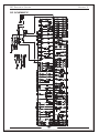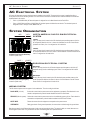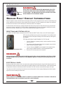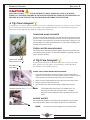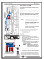
1
420 spOrt COupe HIN: MQYU3006C111 2012 Version 1 Owner’s Guide Marquis Yachts, L.L.C. 790 Markham Drive P.O. Box 1010 Pulaski, WI 54162-1010 USA Phone (920) 822-3214 Fax (920) 822-3213 www.marquisyachts.com Congratulations and Welcome Aboard! This Owner’s Guide was designed to acquaint you with the safe, proper operation and maintenance of your new yacht and its systems. Your first duty as Captain of your new Marquis yacht should be to read your Owner’s Guide and all manufacturer-supplied operating and maintenance instructions found within your Owner’s Information kit. Be sure to mail in all manufacturer registrations and warranty cards to validate your Marquis Yachts' and OEM warranties. These warranty cards have been assembled and are contained in the OEM information packets within your Owner’s Information kit. Marquis Yachts is proud to be supported by an exclusive network of experienced and knowledgeable dealers. If you have any questions regarding your new yacht including warranty please contact your selling dealer. Please read all of your warranties carefully and remember that your selling dealer is your point of contact for all questions and warranty issues. If you’re new to boating, learn the proper rules of seamanship to ensure the safety of your passengers. Refer to Chapman’s Piloting, Seamanship and Small Boat Handling and attend a safe boating class offered by the U.S. Coast Guard Auxiliary, United States Power Squadron, or any enterprise experienced in conducting safe boating courses. Thank you for choosing Marquis Yachts. We’re confident your new yacht will provide you and your family with years of enjoyable cruising. Robert VanGrunsven President Table of ConTenTs PREFACE SECTION 4 - INTERNAL SYSTEMS Using Your Owner’s Information Kit . . . . . . . . . . . . . . . . . . . . . v Owner’s Guide . . . . . . . . . . . . . . . . . . . . . . . . . . . . . . . . . . . . . . v OEM Information . . . . . . . . . . . . . . . . . . . . . . . . . . . . . . . . . . . . v Pre-Delivery Service Record . . . . . . . . . . . . . . . . . . . . . . . . . . .vi Warranty Registration . . . . . . . . . . . . . . . . . . . . . . . . . . . . . . . .vi Air Conditioning System . . . . . . . . . . . . . . . . . . . . . . . . . . . . . 37 Fresh Water System . . . . . . . . . . . . . . . . . . . . . . . . . . . . . . . . 38 Bilge System . . . . . . . . . . . . . . . . . . . . . . . . . . . . . . . . . . . . . . 43 Sanitation System . . . . . . . . . . . . . . . . . . . . . . . . . . . . . . . . . . 46 Raw Water Washdown . . . . . . . . . . . . . . . . . . . . . . . . . . . . . . 48 SECTION 1 - BOATING SAFETY SECTION 5 - PROPULSION Safe Operation . . . . . . . . . . . . . . . . . . . . . . . . . . . . . . . . . . . . . 1 Emergency Procedures . . . . . . . . . . . . . . . . . . . . . . . . . . . . . . . 3 Safety Equipment . . . . . . . . . . . . . . . . . . . . . . . . . . . . . . . . . . . 5 Owner’s Responsibilities . . . . . . . . . . . . . . . . . . . . . . . . . . . . . . 8 Carbon Monoxide (CO) Warnings . . . . . . . . . . . . . . . . . . . . . . 10 Preventing CO Exposure . . . . . . . . . . . . . . . . . . . . . . . . . . . . . 11 Identifying CO Exposure . . . . . . . . . . . . . . . . . . . . . . . . . . . . . 12 Treating CO Exposure . . . . . . . . . . . . . . . . . . . . . . . . . . . . . . . 12 Other Health and Safety Information . . . . . . . . . . . . . . . . . . . . 12 Warning Labels . . . . . . . . . . . . . . . . . . . . . . . . . . . . . . . . . . . . 12 Fuel Systems . . . . . . . . . . . . . . . . . . . . . . . . . . . . . . . . . . . . . 51 Engine Room Ventilation . . . . . . . . . . . . . . . . . . . . . . . . . . . . . 52 Cooling System . . . . . . . . . . . . . . . . . . . . . . . . . . . . . . . . . . . . 52 Exhaust System . . . . . . . . . . . . . . . . . . . . . . . . . . . . . . . . . . . . 53 Fire Suppression System . . . . . . . . . . . . . . . . . . . . . . . . . . . . 54 Engine Gauges . . . . . . . . . . . . . . . . . . . . . . . . . . . . . . . . . . . . 55 Helm Controls . . . . . . . . . . . . . . . . . . . . . . . . . . . . . . . . . . . . . 55 Preparing for Cruising . . . . . . . . . . . . . . . . . . . . . . . . . . . . . . . 57 SECTION 2 - DC ELECTRICAL SYSTEM Batteries . . . . . . . . . . . . . . . . . . . . . . . . . . . . . . . . . . . . . . . . . 15 Battery Maintenance . . . . . . . . . . . . . . . . . . . . . . . . . . . . . . . . 16 Operating the DC Equipment . . . . . . . . . . . . . . . . . . . . . . . . . 17 DC Control Center (Engine Room) . . . . . . . . . . . . . . . . . . . . . 17 DC Control Panel (Helm) . . . . . . . . . . . . . . . . . . . . . . . . . . . . . 20 DC Schematic . . . . . . . . . . . . . . . . . . . . . . . . . . . . . . . . . . . . . 25 SECTION 3 - AC ELECTRICAL SYSTEM AC Electrical System . . . . . . . . . . . . . . . . . . . . . . . . . . . . . . . . 27 System Organization . . . . . . . . . . . . . . . . . . . . . . . . . . . . . . . . 27 Shore Power . . . . . . . . . . . . . . . . . . . . . . . . . . . . . . . . . . . . . . 28 Generator Power . . . . . . . . . . . . . . . . . . . . . . . . . . . . . . . . . . . 30 Operating AC Equipment . . . . . . . . . . . . . . . . . . . . . . . . . . . . . 32 AC Control Center (Salon) . . . . . . . . . . . . . . . . . . . . . . . . . . . . 32 Ground Fault Circuit Interrupters . . . . . . . . . . . . . . . . . . . . . . . 34 Electrical Loads . . . . . . . . . . . . . . . . . . . . . . . . . . . . . . . . . . . . 34 Bonding System . . . . . . . . . . . . . . . . . . . . . . . . . . . . . . . . . . . 34 AC Schematic . . . . . . . . . . . . . . . . . . . . . . . . . . . . . . . . . . 35,36 3837• U3 11/11 SECTION 6 - OPERATING AND . . . . . . MANEUVERING Launching the Yacht . . . . . . . . . . . . . . . . . . . . . . . . . . . . . . . . 61 Navigation . . . . . . . . . . . . . . . . . . . . . . . . . . . . . . . . . . . . . . . . 61 Controlling the Yacht . . . . . . . . . . . . . . . . . . . . . . . . . . . . . . . . 61 Anchoring/Mooring . . . . . . . . . . . . . . . . . . . . . . . . . . . . . . 62-63 Getting Underway . . . . . . . . . . . . . . . . . . . . . . . . . . . . . . . . . . 64 Trim System . . . . . . . . . . . . . . . . . . . . . . . . . . . . . . . . . . . . . . 65 SECTION 7 - MAINTENANCE Maintenance Schedule . . . . . . . . . . . . . . . . . . . . . . . . . . . . . . 67 Exterior Maintenance . . . . . . . . . . . . . . . . . . . . . . . . . . . . . . . . 69 Interior Maintenance . . . . . . . . . . . . . . . . . . . . . . . . . . . . . . . . 74 Mechanical Systems . . . . . . . . . . . . . . . . . . . . . . . . . . . . . . . . 75 Teak Deck . . . . . . . . . . . . . . . . . . . . . . . . . . . . . . . . . . . . . . . . 77 SECTION 8 - WINTERIZATION AND . . STORAGE Winterization - Storage . . . . . . . . . . . . . . . . . . . . . . . . . . . . . . 79 Winterization - Systems . . . . . . . . . . . . . . . . . . . . . . . . . . . . . . 79 Spring Recommissioning Checklist . . . . . . . . . . . . . . . . . . 84-85 Table of ConTenTs SECTION 9 - WARRANTY AND PARTS Warranty Information . . . . . . . . . . . . . . . . . . . . . . . . . . . . . . . . 87 Obtaining Warranty Service . . . . . . . . . . . . . . . . . . . . . . . . . . . 88 Second and Third Owner Registration . . . . . . . . . . . . . . . . . . 88 Hull Identification Number . . . . . . . . . . . . . . . . . . . . . . . . . . . . 88 OEMs . . . . . . . . . . . . . . . . . . . . . . . . . . . . . . . . . . . . . . . . . . 88 Specifications . . . . . . . . . . . . . . . . . . . . . . . . . . . . . . . . . . . . . 88 Bill of Material . . . . . . . . . . . . . . . . . . . . . . . . . . . . . . . . . . . . . 90 Marquis Limited Warranty . . . . . . . . . . . . . . . . . . . . . . . . . . . . 91 OPTIONS Passerelle . . . . . . . . . . . . . . . . . . . . . . . . . . . . . . . . . . . . . . . . 93 Transom Capstan . . . . . . . . . . . . . . . . . . . . . . . . . . . . . . . . . . 93 Electronics . . . . . . . . . . . . . . . . . . . . . . . . . . . . . . . . . . . . . . . . 94 Swim Platform . . . . . . . . . . . . . . . . . . . . . . . . . . . . . . . . . . . . . 94 3837 • U3 11/11 PrefaCe Lower HeLm ControLs 3837• U3 11/11 i PrefaCe Using tHe owner's information Kit THE OWNER’S INFORMATION KIT CONTAINS: Qty. Item 1 Owner’s Guide (Varies) OEM information Please read the Owner’s Guide and OEM (Original Equipment Manufacturer) information carefully . Become familiar with the yacht, its components, and systems before attempting to operate . The Owner’s Information kit must be onboard when the yacht is in operation . If the yacht gets sold, the new owner must receive the Captains Kit . NOTE: OWNER’S GUIDE The Owner's Guide purpose is to explain how to safely operate and maintain the yacht and it's various systems . The Owner's Information Kit also contains safety precautions and operation tips, as described below: PRECAUTION DESCRIPTION DaNgEr Describes a hazard that can cause death or severe injury if the instructions are ignored . WarNiNg Describes a hazard that can cause serious injury and/or property damage if the instructions are ignored . CauTiON Describes a hazard that can cause damage to the yacht or its components if the instructions are ignored . NEvEr Describes a user based hazard that should NEVER be performed . NOTE: Provides important information that can help avoid problems . A Tip From Marquis! Provides various tips to keep the yacht in top condition Please obtain handling and operation experience before operating your new yacht . Gaining experience is important if this is your first yacht, or if changing to a type of yacht that is unfamiliar . Gaining experience is for your own comfort and safety . Your dealer, national sailing federation, or yacht club can advise local sea schools or competent instructors . NOTE: Drawings and illustrations contained within this guide are included as graphic aids to assist in the general operation and maintenance of the yacht . The drawings and illustrations are used for graphic purposes only . The drawings do not include all of the details of each system, and the drawings are not to scale . Do not reference the drawings to order parts or to service the yacht . Contact an authorized Marquis Dealer for parts or service required . A Tip From Marquis! Many people within the Marquis organization are avid boaters. Some of the experience gained during our years of boating are presented in this Owner's Guide. The information is presented under the heading, “A TIP FROM Marquis.” The information contained within the Owner’s Guide is complete and accurate at the time the guide was printed . Marquis Yachts reserves the right to change materials, part numbers, specifications, or system designs at any time without notice. ii 3837 • U3 11/11 PrefaCe OEM INFORMATION The OEM (Original Equipment Manufacturer) information is supplied by companies from whom Marquis Yachts has purchased components to install in your yacht . These components include, but are not limited to, standard items: • Engines • Sanitation System • Pumps and Batteries • Other additional Item The OEM information explains how to operate and maintain the components . If you install an aftermarket accessory on your yacht, add the OEM information that accompanies the accessory to the Owners's Information Kit NOTE: If the OEM information conflicts with this Owner's Guide, follow the instruction in the OEM information . PRE-DELIVERY SERVICE RECORD The Pre-Delivery Service Record, on the following page, must be completed and signed by your Marquis Dealer before the yacht can be delivered . Your Marquis Dealer will prepare the yacht for delivery in accordance with the procedures detailed within this document . Make sure the Pre-Delivery Service Record and all OEM warranty cards have been completed and mailed to the companies listed . Make sure to retain a copy of the Pre-Delivery Service Record for your own reference . WARRANTY REGISTRATION Marquis Yachts warrants every yacht the company manufactures, as explained in the Marquis Limited Warranty . The owner's copy of the warranty is located in Section 9 . Please review the warranty carefully . The Warranty Registration on the following page is the first step in activating your Marquis Yachts limited warranty . This document must be completed and signed by you and your Marquis Dealer before taking delivery of the yacht . Failure to complete and register the Warranty Registration could void the Marquis Yachts limited warranty . Your Marquis Dealer will review the terms of the Marquis Yachts warranty, and make sure the warranty is registered with Marquis Yachts . To ensure the warranty remains in effect during its lifetime, Marquis Yachts, your Marquis Dealer, and you (the owner) must each uphold specific responsibilities . The following responsibilities are described in Section 9 . At time of delivery, make a complete inspection of the yacht and its systems . Document any work that needs to be completed by the Dealer to meet the terms of your agreement . Two cards are located at the end of the Preface . The cards are Second and Third Owner Registration Cards . Marquis strongly recommends that the purchaser of a previously-owned Marquis, register ownership with Marquis Yachts . 3837• U3 11/11 iii PrefaCe WarNiNg Marquis recoMMends that no persons be allowed to ride on the forward sunpad while the yacht is under power. sudden turning of the yacht or unseen wave surge can cause loss of balance resulting in injury or falling overboard. iv 3837 • U3 11/11 MARQUIS YACHTS, L.L.C. OWNER REGISTRATION PO BOX 1010 PULASKI, WI 54162-1010 MARQUIS YACHTS, L.L.C. OWNER REGISTRATION PO BOX 1010 PULASKI, WI 54162-1010 tHIRD OWNeR ReGIStRAtION Owner's Name: ______________________________________________ Street Address: ______________________________________________ City: _____________________ State: _______ Zip Code: ____________ telephone: ( ___) __________________Date of Purchase: ___________ Purchased From: _____________________________________________ Boat Hull Identification Number: CDR ___________________________ third Owner Registration does not extend, alter, or transfer the marquis Limited Warranty. Refer to the marquis Limited Warranty for details. SeCOND OWNeR ReGIStRAtION Owner's Name: ______________________________________________ Street Address: ______________________________________________ City: _____________________ State: _______ Zip Code: ____________ telephone: ( ___) __________________Date of Purchase: ___________ Purchased From: _____________________________________________ Boat Hull Identification Number: CDR ___________________________ Second Owner Registration does not extend, alter, or transfer the marquis Limited Warranty. Refer to the marquis Limited Warranty for details. YaChTing safeTY seCTion 1 YaCHting safetY YACHTING SAFETY IS YOUR RESPONSIBILITY . Fully understand the operating procedures and safety precautions outlined in the Owner’s Information Kit and this Owner’s Guide before operating the yacht . safe yachting is no accident . SAFE OPERATION SAFE OPERATION INCLUDES, BUT IS NOT LIMITED TO, THE FOLLOWING: • Keep the yacht and equipment in safe operating condition . Inspect the hull, engines, safety equipment, and all yachting gear regularly . NOTE: • • • • • • • • • • • • • • • • • Federal law requires the owner to provide and maintain safety equipment onboard . Consult the U .S . Coast Guard, state, and local regulations to ensure all required safety equipment is onboard . Additional equipment may be recommended for your safety and the safety of the passengers . Become aware of the safety equipment’s availability and use . Use caution when fueling the yacht . Understand the fuel tank’s capacity, and fuel amount used when operating at frequently used engine speeds (RPMs) . Make sure enough fuel is stored for cruising requirements . Know the tank’s cruising radius and fuel tank range . Typical tank usage: 1/3 of the supply to reach the destination, 1/3 to return, and keep1/3 in reserve for changes in plans due to weather or other circumstances . always keep fire extinguishing and lifesaving equipment onboard . The safety equipment must meet regulatory standards, and should be noticeable, accessible, and in proper operating condition . Passengers onboard should know of the equipment’s location, and how to use each piece of equipment . Keep an eye on the weather . Be aware of possible changing conditions by checking local weather reports before departure . Monitor strong winds and electrical storms . Always keep accurate, updated charts of the areas chosen to cruise . Keep back up charts if a chart plotter is used . File a Float Plan with a family member, relative, friend, or other responsible person ashore before departure from PORT or harbor . Always practice safe yachting, courtesy, and common sense . Instruct at least one passenger onboard with the yacht’s basic operation . The designated person can take over if the operator is unexpectedly, unable to maintain control . do not allow passengers to ride anywhere other than designated seating areas . Ask all passengers to remain seated while the yacht is in motion . do not use the boarding platform or boarding ladder, while either of the engines are running . Both engines must be shut off . understand and obey the “rules of the road.” Always maintain complete control of the yacht . do not overload or improperly load the yacht . See Section 9: Load Capacity, for instructions on maximum capacity do not travel faster than conditions warrant or beyond your abilities . do not operate the yacht in weather or sea conditions beyond your skill and experience . do not operate the yacht while under the influence of drugs and/or alcohol . do not operate the yacht if visually impaired . adverse Conditions WEATHER All passengers should be aware of present weather conditions and the weather forecast at all times . Check the forecast before beginning a day of yachting . However, be aware that weather conditions can change rapidly . If a marine radio is onboard: • Listen to the weather reports issued by the U .S . Coast Guard and other sources . 3837 • U3 11/2011 1 YaChTing safeTY seCTion 1 If a portable radio is onboard: • Keep the radio tuned to a station broadcasting frequent weather reports . Many yachting clubs fly weather signals; learn to recognize the following weather signals . WEATHER SIGNALS STORM PREPARATION Storms rarely appear without advance notice . If a storm is a possibility, keep a watch on the horizon, especially to the West, for the storm’s approach . Watch for changes in wind direction or cloud formations . Understanding the weather conditions, and what to do when the weather takes a turn for the worse is important . If a storm is approaching, the best course of action is to return to PORT . If unable to return, prepare to weather the storm . To do so: • Close portlights, exterior doors and hatches and secure them . Stow all loose gear below deck, and tie down any gear on deck . • Reduce speed as the seas build . • Make sure all persons onboard are wearing the personal flotation devices . • Drop a sea anchor over the stern to maintain the bow into the seas . If a sea anchor is unavailable, use a canvas bucket, tackle box, or other object that will replace the anchor . FOG Fog is a result of either warm-surface or cold-surface conditions . Periodically measure the air temperature and dew point temperature to determine the liability of fog formation . Fog is likely to develop if the difference between the air temperature and dew point temperature is small . Remember the following guidelines: • Head for shore at the first sign of fog, unless the yacht is well equipped with charts and navigational equipment and wait until conditions improve . If charts are available onboard: take bearings as fog sets in, mark the current position, and continue to log the course and speed . • All persons onboard should put on their personal flotation devices . • If sound equipment is installed, check soundings regularly and match the sounds with depths shown on the charts . • Station a person forward in the yacht as a lookout . • Reduce speed . Periodically, stop the engines and listen for surrounding fog signals . • Sound the horn or fog bell intermittently to warn others . 2 3837 • U3 11/2011 YaChTing safeTY • seCTion 1 Set anchor if there is doubt in continuing the cruise . Listen for other fog signals while continuing to sound the fog horn or bell . emergenCY ProCedUres It is important to obtain training to handle any emergency that may arise . The following is not an exhaustive list of situations that may be encountered while yachting; however, this section serves as a guide to aid in emergencies . FIRE To help prevent a fire onboard the yacht: • Keep the bilges clean and check for fuel vapors at regular intervals . NEvEr r • • never fit free-hanging curtains or other fabrics near, or above the stove top, or other highheat devices. never store Materials or equipMent of any kind in the engine rooM. DaNgEr any fire onboard the yacht is serious. eXplosion is possible. develop a fire response plan. respond iMMediately to any eMergency. every yachter should develop a fire response plan. the plan should deterMine: • the type of fire (fuel, electrical, etc.) • where the type of fire, listed above, Might break out • the best way to react have a plan. assign responsibilities to others to allow quick decisions and reactions. NEvEr • • • • • • • • never obstruct passage ways to eXits and hatches. never obstruct safety controls, such as fuel valves and electrical systeM switches. never obstruct portable fire eXtinguishers in lockers. never leave the yacht unattended while cooking, or while heating appliances are in use. never use gas lights in the yacht. never Modify any of the yacht’s systeMs, especially electrical or fuel. never fill the fuel tanks while: Machinery is running, while cooking, or heating appliances are in use. never sMoke while handling fuel. NOTE: Everyone onboard should know of the fire extinguisher locations, and how to operate the extinguishers . IN CASE OF FIRE • • • • • • Stop the engines immediately . Shut off the bilge blowers immediately if the fire is in the engine room . do not open the hatch to the engine room . The fire will flare up if the fresh air supply increases suddenly . Keep the fire downwind if possible . Head into the wind if the fire is aft of the yacht . Have all persons onboard put on their personal flotation devices . If the fire is accessible . use the fire eXtinguisher . 3837 • U3 11/2011 3 YaChTing safeTY seCTion 1 It is the owner and/or crew’s decision to abandon the yacht . If the decision is to abandon ship, all persons onboard should jump overboard, and swim to a safe distance away from the burning yacht . FLOODING If water is leaking in the hull, and the yacht is taking on water: 1 . Turn ON the bilge pumps . 2 . Assign someone to bail out the bilge and investigate the cause of the flooding . 3 . Attempt to repair the yacht when the source of the leak is found . Almost anything can be stuffed into the opening to stop the leaking temporarily . Leak plugging material will work better if applied from the exterior where water pressure can aid in stopping the leak . Station a crew member to hold the plug in place if the plug is applied from the inside . In all cases, assign a crew member or passenger to watch the plugged area and alert others if the plug fails . SWAMPED OR CAPSIZED YACHT IMMEDIATELY PUT ON A PERSONAL FLOTATION DEVICE, AND SET OFF A DISTRESS SIGNAL IF THE YACHT BECOMES SWAMPED OR CAPSIzED . Chances are good that a capsized yacht will stay afloat . To ensure the safety of the crew and yacht, it is important to: • Stay with the yacht, unless an emergency situation occurs . • Do not leave the yacht or try to swim to shore except under extreme conditions . • Remember, a capsized yacht is easier to see than a swimmer • Remember, the shore may be further away than it appears . To reduce the occurrence of a swamped or capsized yacht: 1 . 2 . 3 . Reduce headway and turn the yacht slightly if water is coming over the bow . Turn the yacht so the bow is slightly off from meeting the waves head on . Drop a sea anchor over the stern, and adjust the length of the line to hold the bow at the most favorable angle . COLLISION If a serious collision occurs, check everyone onboard for injuries, then inspect the entire yacht to determine the extent of the damage . • • • • • • Prepare to help the other craft unless your yacht or passengers are in danger . If the hull has been penetrated, prepare to plug the fracture once the colliding yachts have been separated . Shore up the hole inside of the yacht with a spare life jacket or bunk cushion . Trim weight, if possible, to get the hole above the water level during repairs . If the yacht is in danger of sinking, have everyone onboard put on the personal flotation devices . If a radio is installed, immediately, contact the U .S . Coast Guard or other rescue authorities on VHF channel 16 or CB radio channel 22 . (VHF channels 9 or 13 or a cellular phone in some states may be available) . RUNNING AGROUND Excessive weight in the fore or aft sections of the yacht will cause a trim change, and may yield greater draft than expected . Equip the yacht with a quality depth-measuring instrument, and allow ample water below the hull while operating . IF THE YACHT RUNS AGROUND: • • Check everyone onboard for injuries Inspect the yacht for damage . IF LIGHTLY GROUNDED: • Shift the weight of the passengers or gear to heel the yacht while reversing engines . IF TOWING bECOMES NECESSARY: • 4 Use a commercial towing service . 3837 • U3 11/2011 YaChTing safeTY seCTion 1 NEvEr never attach a tow line to a single deck cleat or anchor windlass. The cleats and windlass are not designed to take the full load of the yacht and may pull free from the deck, causing serious injury or property damage . MAN OVERbOARD In the event that someone falls overboard, understanding what to do is important . Emergency procedures are published in Chapman Piloting publications, and instruction is offered by the U .S . Coast Guard . Hypothermia may be an immediate concern if a person falls overboard . Hypothermia occurs when a person’s body loses heat faster than the body can replace it . The person will become exhausted or likely drown if not rescued in a timely manner . The colder the water, the faster body’s heat is lost . Personal flotation devices increase survival time because they provide insulation . To understand the survival time to water temperature ratio, see the “Water Survival Chart” below: WATER SURVIVAL CHART water temp. (°f) 32 .5 32 .5-40 40-50 50-60 60-70 70-80 Over 80 exhaustion unconsciousness Under 15 min . 15-30 min . 30-60 min . 1-2 hr . 2-7 hr . 3-12 hr . Indefinite expected time of survival Under 45 min . 30-90 min . 1-3 hr . 1-6 hr . 2-40 hr . 3 hr .- Indefinite Indefinite MEDICAL EMERGENCY • • • No one should act as a doctor, if not properly trained . Someone onboard should know first aid . First aid training is available through your local Red Cross . Keep a fully stocked first aid kit onboard at all times . EQUIPMENT FAILURE • • Steering, propulsion, and control failure can be prevented by having the yacht maintained and checked periodically . Radio for help or signal with flags and wait for help if the systems fail . RADIO COMMUNICATION (U.S. ONLY) It is the yachter’s responsibility to obtain a radio operator’s permit, and follow and understand proper rules and procedures . Private yachts are not required to have a radio on board at all times . However, if a radio is available, it should be tuned to channel 16 unless it is being actively used . Channel 16 is the frequency for emergency calls or initial calls between yachts . Once contact is established on channel 16, change the frequency to channel 22 . Additional information on radio communications can be found in Chapman’s Piloting publications . DISTRESS SIGNALS The yacht operator is required, by law, to lend assistance to a craft in distress . Assistance must be given as long as your life or yacht is not put in harm’s way in the process . In the United States, Good Samaritan laws protect the public from liability incurred while giving aid . safetY eqUiPment NOTE: Sections of this chapter titled: Safety Equipment and Owner’s Responsibilities applies to US regulations 3837 • U3 11/2011 5 YaChTing safeTY seCTion 1 regulations to ensure that all the required safety equipment is onboard . It is the owner’s responsibility to learn about additional recommended equipment before operating their yacht . PERSONAL FLOTATION DEVICES (PFD’S) • • • A minimum of one personal flotation device is required for each person onboard . The PFD must be U .S . Coast Guard-approved wearable (Type I, II, or III) . The PFD’s must be readily accessible and in serviceable condition . The PFD’s must be of a suitable size for each person onboard . • A minimum of three PFD’s (two wearable and one throwable) are required regardless of the number of persons onboard . PFD TYPE I, WEARAbLE: • • Type I is the most effective life preserver for all waters when rescue may be delayed . Type I is designed to turn most unconscious or drowning people from a facedown position to a vertical or face-up position . PFD TYPE II, WEARAbLE: • • Type II is a near-shore buoyant vest . Type II is intended for calm inland waters when a quick rescue is anticipated . Type II turns the person to a face up position, but the turning action is not as evident as the Type I . Type II will not typically turn people over in the same manner as Type I . PFD TYPE III, WEARAbLE: • • Type III is classified as a flotation aid; however, the device will not turn a victim to a face-up position . Type III is frequently used in water sports, and SHOULD BE AVOIDED IN PERSONAL YACHTING . PFD TYPE IV, THROWAbLE: • • • • At least one throwable Type IV PFD device is required onboard at all times . Type IV PFD does not strap to the user . Type IV PFD must be thrown to a person in the water and held by the user until rescued . The most common Type IV PFD’s are buoyant cushions or ring buoys . • Type IV PFD must be in serviceable condition and immediately available for use . VISUAL DISTRESS SIGN (VDS) Visual distress signal equipment is required by the U .S . Coast Guard for all yachts operating on U .S . coastal waters . Yachts owned in the United States and operating on the high seas must also carry VDS equipment . The visual distress equipment signal must be readily accessible and in serviceable condition . Both pyrotechnic and non-pyrotechnic equipment must be U .S . Coast Guard approved . Both types of distress signal equipment can become ineffective with age . Replace the equipment before taking the yacht out if the equipment’s usage date has expired . APPROVED PYROTECHNIC EQUIPMENT INCLUDES: • • • Hand held or aerial red flares Hand held or floating orange smoke Launchers for aerial red meteors or parachute flares APPROVED NON-PYROTECHNIC EQUIPMENT INCLUDES: • • • Orange distress flag Dye markers Electric distress light . No single signaling device is ideal under all conditions . Carrying a variety of visual distress signal equipment onboard is important . Select devices with packaging that children ONLY will find difficult to open, especially if children are onboard . 6 3837 • U3 11/2011 YaChTing safeTY seCTion 1 SOUND SIGNALING DEVICE The yacht must be equipped with an operable device that can produce a sound signal if conditions require . Required sound devices include: • One horn is standard on all Marquis models . • Yachts longer than 39’ 4”, one bell and one whistle is required . The devices must meet the Inland Navigational Rules Act of 1980 . For details on the appropriate signals, refer to the Navigational Rules published the U .S . Coast Guard, International-Inland . RUNNING AND NAVIGATION LIGHTS • • • • Running and navigation lights must be turned on for safe operation after dark . Observe all navigation rules for meeting and passing . Do not run at high speeds during night operation . Always use common sense and good judgment while cruising at night . RADAR REFLECTORS Radar reflectors, if installed, should measure at least 18” diagonally . The reflectors should be placed 12’-0” above the waterline to ensure that other yachts with radar reflectors have sight of your yacht . FIRE EXTINGUISHERS Fire extinguishers must be approved by the U .S . Coast Guard . The U .S . Coast Guard classifies fire extinguishers by the type of fire the extinguisher can extinguish . The fire extinguisher classifications include: foam, carbon dioxide, chemical, and Halon . Below is the standard extinguishing equipment on the yacht: yachts longer than 40’ and shorter than 65’: The yacht has a fixed fire extinguishing system approved by the U .S . Coast Guard . It is the owners responsibility to install either: Two Type B-I (or) one Type B-II extinguisher is on board . All fire extinguishers should be mounted in a readily accessible location, away from the engine room . Everyone onboard should know of the fire extinguisher locations, and how to operate the extinguishers . If a charge indicator gauge is equipped on the fire extinguisher, cold or hot weather may affect the gauge reading . Consult the manufacturer’s manual supplied with the fire extinguisher to determine the gauge accuracy . Check and maintain the fire extinguishing equipment in accordance with the manufacturer’s recommendations . Replace fire fighting equipment if expired or discharged . Replace with devices of identical or greater fire fighting capacity . RECOMMENDED EQUIPMENT In addition to the required equipment, Marquis recommends carrying the following: • Spare anchor • Tool kit • Heaving line • Ring buoy • Fenders • Navigational charts • Flashlight • Mooring lines • Mirror • Binoculars • Suntan lotion • Spare parts • Spare propeller(s) • Spare pump owner’s resPonsibiLities SAFE YACHTING COURSES Your local U .S . Coast Guard Auxiliary and the U .S . Power Squadrons offer comprehensive safe yachting classes several times per 3837 • U3 11/2011 7 YaChTing safeTY seCTion 1 The United States Inland Rules applies to all vessels inside the demarcation lines separating inland and international waters . The U .S . Coast Guard lists the traffic regulations in the Navigational Rules, International-Inland publication . A copy can be obtained from a local U .S . Coast Guard Unit or the United States Coast Guard Headquarters at: 1300 E . Street NW, Washington, D .C . 20226 . Other helpful publications available from the U .S . Coast Guard include: • Aids to Navigation (U .S . Coast Guard pamphlet #123), publication explains the significance of various lights and buoys • Yachting Safety Training Manual • Federal Requirements for Recreational Yachts Check with your local U .S . Coast Guard station, your Marquis Dealer, or a local marina about navigational aids unique to your area . DOCUMENTATION A Certificate of Number is issued to a yacht owner registered with the U .S . Coast Guard . The certificate must be onboard when the yacht is in use . State registration is required . Check with the U .S . Coast Guard, or your state regulatory agency, to determine what other records are required onboard . The following logs are strongly recommended to be maintained, in addition to the required documents . Log books are available from maritime supply stores . The recommended logs include: • navigation log, containing: engine speeds, compass courses, and time records is essential for both cruising and maintenance purposes . • radio log: mandatory on vessels that are required to carry a radio . A radio log can be useful to record unusual events, especially for future litigation . • Maintenance log: used to track the type and frequency of maintenance procedures performed on the yacht and the yacht’s systems . Refer to Section 7 for additional information on yacht maintenance . • an engine/fuel log: essential for calculating range and fuel requirements . • gps log: used if a GPS is equipped onboard . DRUGS AND ALCOHOL Drugs and alcohol adversely affect a person’s ability: to make sound judgments, react quickly, and operate a yacht safely . As a responsible yachter, it is strongly recommenced to refrain from using drugs or alcohol while operating the yacht . Operating a motorized yacht while under the influence of drugs or alcohol carries a significant penalty . DISTRESS CALLS If a ship-to-shore radio telephone is installed, heed storm warnings, and answer any distress calls from other yachters . The word “Mayday” spoken three times is the international signal of distress . Monitor marine radio channel 16 is reserved for emergency and safety messages . Channel 16 is also used to contact the U .S . Coast Guard or other yachters if there is trouble . NEvEr r never send a “Mayday” Message unless there is a serious eMergency and iMMediate assistance is required. VOLUNTARY INSPECTIONS Courtesy inspections are offered by the U .S . Coast Guard Auxiliaries or State Yachting Officials in many states to ensure that all yachts comply with safety standards, and the required safety equipment is onboard . After a voluntary inspection, time is given to make corrections without prosecution . Check with the appropriate state agency or the U .S . Coast Guard Auxiliary for details . YACHTING ACCIDENTS A vessel used for recreational purposes is required to file a report when: • An accident resulting in loss of life or disappearance from a vessel 8 3837 • U3 11/2011 YaChTing safeTY • • • seCTion 1 An injury requiring medical treatment beyond first aid Property damage in excess of $200 Complete loss of the vessel . In cases of death and injury, reports must be submitted within 48 hours . All other cases, reports must be submitted within 10 days . Reports must be submitted in the state where the accident occurred . YACHTING REGULATIONS It is the owner’s responsibility to make sure that the yacht is in compliance with all federal, state, and local regulations . Check with your local U .S . Coast Guard office for relevant federal regulations . Your state’s Department of Natural Resources may have some publications available that deal with relevant state laws . GARbAGE Dumping garbage into the sea is a worldwide problem . U .S . Coast Guard regulations prohibit dumping plastic refuse and garbage mixed with plastic into any waters, and restrict the dumping of other forms of garbage . IT IS ESSENTIAL THAT ALL YACHTERS HELP TO CLEAN OUR WATERWAYS BY PROPERLY DISPOSING OF ALL GARBAGE . OIL The Federal Water Pollution Control Act prohibits the discharge of oil or oily waste into or upon the navigable waters and contiguous zone of the United States . Violators are subject to a significant fine if such discharge causes a film or sheen upon or discoloration of the surface of the water, or causes a sludge or emulsion beneath the surface of the water . SEPTIC WASTE It is illegal to discharge septic waste directly overboard on U .S . inland and coastal waters . If an overboard discharge is installed, check with a local U .S . Coast Guard office to ensure that compliance is met with federal regulations . STATE AND LOCAL ORDINANCES State or locality may have laws limiting: speed, noise, or the yacht’s wake . Check with the local harbor master if certain yachting operations are restricted by local ordinances or state laws . Check with state and local authorities to confirm compliance with local regulations regarding: marine sanitation, noise, speed, and wake . Pre-Departure Actions: • Check the weather . Make sure conditions and seas will not be hazardous during your outing . • Make sure all safety equipment is onboard, accessible, and in good working condition . • Check the bilge for fuel vapor or water . Ventilate or pump out the bilge as necessary . • Make sure the horn, navigation equipment, and lights are working properly . • Instruct guests and crew in safety and operational matters . • Check engine oil, transmission oil, and coolant levels . • After starting the engines, check: • The overboard flow of cooling water • Engine temperatures • Oil pressures • Fill the fuel tanks as needed . Know the tank capacity and fuel consumption at various RPM’s . Know the tank’s cruising radius and fuel tank range . Typical tank usage: 1/3 of the supply to reach the destination, 1/3 to return, and keep1/3 in reserve for changes in plans due to weather or other circumstances . • Have a second person onboard capable of taking over operating the yacht in case the operator is disabled . • Before departing, inform a friend or relative of the intended cruising area, and the intended return time; so if delayed, the US Coast Guard can be contacted . Remember, to tell the contact person of your return to prevent false alarms . Do not file a float plan with the U .S . Coast Guard . The Coast Guard does not have the manpower to monitor all yachts . • Stow all loose gear securely . Fenders and docklines should be stowed immediately after getting underway . 3837 • U3 11/2011 9 YaChTing safeTY seCTion 1 Carbon monoxide (Co) warnings CO detectors are standard on all Marquis yachts . Have the detectors professionally calibrated at regular intervals . DaNgEr r carbon MonoXide (co) is a colorless, odorless, and tasteless gas eMitted through engine and generator eXhaust. prolonged eXposure to co can result in unconsciousness, brain daMage, and death. carbon MonoXide (co) will cause serious injury or death. stay clear froM the eXhaust port when the engine is running. CO2 Illustration: 1 .1 people sleeping onboard can easily be overcoMe by carbon MonoXide. do not sleep while the engines or generators are running. CO2 Illustration: 1 .2 PREVENTING CO EXPOSURE Open a forward hatch, porthole, or window to help prevent the accumulation of CO in the cabin and enclosed exterior areas . Creating air circulation allows air to travel through the yacht’s interior . Have a trained marine technician inspect the exhaust systems when the yacht is in for service, or if a change in the sound of an engine or the generator is noticed . See CO Illustration above . TO PREVENT SERIOUS INjURY OR DEATH bY ASPHYXIATION: • • • • Keep the engine room hatch closed when operating the engines and generator . Do not occupy aft lounging areas, including: the boarding platform, or swimming near the engine or generator exhaust outlets while the engines or generator are running . Minimize the time spent getting underway; CO production is greater when the engines are cold . Maintain the propulsion and generator engines to optimize efficiency, which reduces CO emissions . For additional information on carbon monoxide and yachting, please contact marine organizations that produce safety publications . For information on receiving a free VESSEL SAFETY CHECK, visit www .vesselsafetycheck .org or contact your local U .S . Coast Guard Auxiliary or United States Power Squadrons® . • U .S . Coast Guard Auxiliary: 1-800-368-5647 or on the Internet at: www .cgaux .org • U .S . Power Squadrons: 1-888-FOR-USPS (1-888-367-8777) or on the Internet at: www .usps .org The following chart displays possible situations where CO can accumulate . Become familiar with the following examples and the suggested precautions to help prevent CO2 poisoning . 10 3837 • U3 11/2011 YaChTing safeTY seCTion 1 Blockage of exhaust outlets can cause carbon monoxide to accumulate in the cabin and cockpit area; even when the hatches, windows, portholes, and doors are closed . warning: never operate the generator while the yacht is Moored against another yacht, dock, or wall structure that could block the eXhaust outlet. Exhaust from another vessel alongside your yacht, while docked or anchored, can emit poisonous CO gas inside the cabin and cockpit areas of your yacht . warning: be alert for generator and engine eXhaust froM other vessels alongside your yacht. provide adequate ventilation. The station wagon effect or back drafting can cause CO gas to accumulate inside the cabin, cockpit, and bridge areas when operating the yacht at a high bow angle or with improper or heavy loading . warning warning: provide adequate ventilation, redistribute the load or bring your yacht out of high bow angle. open forward hatch or window. CO gas can accumulate in the cabin, cockpit and bridge areas when operating your yacht at slow speeds or when the yacht is stopped in the water . A tail wind can also increase accumulation (force of wind entering from aft section of yacht) . warning warning: provide adequate ventilation or slightly increase speed if possible. open forward hatch or window. The station wagon effect or back drafting can cause CO gas to accumulate: inside the cabin, under protective weather coverings, cockpit, or bridge areas when the yacht is underway . warning warning: provide adequate ventilation when the canvas top, side or back curtains are in the closed, protective positions. open forward hatch or window. IDENTIFYING CO EXPOSURE in high concentrations, co can be fatal in Minutes . However, the effects of lower concentrations can also be lethal . Symptoms of exposure to CO are: • Watering and itchy eyes • Flushed appearance • Dizziness • Throbbing temples • Inattentiveness • Vomiting • Inability to think coherently • Loss of physical coordination • Fatigue • Ringing in the ears • Tightness across the chest • Collapse • Headache • Drowsiness • Convulsions • Incoherence / slurred speech • Nausea TREATING CO EXPOSURE If suspected that someone is suffering from CO exposure, take the following actions immediately: • Thoroughly ventilate the area if possible • Evacuate the area and move the affected person(s) to a fresh air environment • Administer oxygen, if available • Get medical assistance • Determine the probable source of the CO and correct the condition . 3837 • U3 11/2011 11 YaChTing safeTY otHer HeaLtH seCTion 1 and safetY information WarNiNg g cancer, birth defects, and other reproductive harM are known by the state of california to be caused by cheMicals eMitted froM engine eXhaust, engine eXhaust constituents, and a variety of coMponents. cancer, birth defects, and other reproductive harM are known by the state of california to be caused by cheMicals contained or eMitted by oils, fuels, and fluids contained in yachts as well as waste produced by coMponent wear. CauTiON always wash your hands, thoroughly, with soap and water to protect your skin. battery posts, terMinals, and related accessories contain lead and lead coMpounds. wash hands after handling used engine oil contains cheMicals that have caused cancer in laboratory aniMals. warning LabeLs Warning labels are posted throughout the yacht to protect everyone onboard, the yacht, the yacht’s equipment, and any personal property onboard . It is important to read, understand, and obey all warning labels . Failure to obey a warning label may result in serious injury or damage to the yacht, the yacht’s equipment, or any personal property on the yacht . WarNiNg g do not sit on the forward sun pad while the yacht is in Motion. injury, falling overboard, or loss of balance can occur if sitting on the forward sun pad while the yacht is in Motion. 12 3837 • U3 11/2011 DC eleCTriCal sYsTem seCTion 2 dC eLeCtriCaL sYstem A 12-volt DC (Direct Current) electrical system is equipped on the 420 SC . The DC system is a comprehensive system designed to meet present and future 12-volt electrical needs . Wire-runs and connections are positioned to prevent abrasion and exposure to moisture, as well as to remain accessible for inspection, repairs, and the addition of aftermarket electrical accessories . Wires used throughout the DC electrical system are plastic coated and color-coded . Connections are made, using crimped connector points . The electrical system is virtually maintenance free, with only the batteries requiring periodic inspection and maintenance . bATTERIES The DC electrical system is divided into three areas, each powered by one or more, 12volt batteries: • Engine Batteries - One for each engine • Accessory Batteries - Two each 12-volt batteries parallel connected to produce 12-volts • Generator Battery - One 12-volt ENGINE bATTERIES engine batteries Each propulsion engine has a designated battery . Electricity from each battery to its engine is controlled by a master disconnect switch (Port Engine Switch shown) . The switches are located in the engine room near the base on the aft bulkhead . Turn ON the master disconnect switches to provide electricity to the engines . (Port Switch Shown) GENERATOR bATTERIES Engine Port Switch The generator has its own dedicated battery . Electricity from the battery to the generator starter is controlled by a master disconnect switch (same as the battery disconnect on Page 1) . The switch is located in the engine room near the base of the aft starboard bulkhead . Turn ON the master disconnect switch to provide electricity to the generator starter . MONITORING bATTERY VOLTAGE LEVELS battery Main disconnect switch (port side) Generator Starter Switch A fully charged battery that has not been charged or discharged for at least two hours should indicate between 12 .3 and 12 .6 volts . A reading below this level indicates a fully charged battery . monitoring batterY voLtage LeveLs A fully charged battery that has not been charged or discharged for at least two hours should indicate between 12 .3 and 12 .6 volts . A reading below this level indicates a fully charged battery . ENGINE bATTERIES The voltage level of each engine battery pair is determined by activating the battery’s dedicated voltmeter . The voltmeters are located at the helm . To activate each engine’s voltmeter, turn the engine’s ignition key one position to the right . Engine Starboard Switch battery Main disconnect switch (starboard side) 3837 • U3 11/2011 13 DC eleCTriCal sYsTem seCTion 2 NOTE: It is not necessary to start the engine to activate its voltmeter . Refer to the OEM information for details on operating the engines . Gauge Panel (Left) needs to be cycled to voltmeters and the engines at idle to indicate a correct running volt . ACCESSORY bATTERIES The voltage level of the accessory batteries is determined by using the voltmeter located on DC Control Panel (Salon) . CHarging tHe batteries CauTiON never allow the boat’s batteries to becoMe coMpletely discharged. coMpletely discharging a battery can daMage it so that the battery can no longer be recharged. the battery charger should always be operating when the boat is connected to shore power. turn all battery Master disconnect switches to the off position if the boat is left for an eXtended period of tiMe and the boat is not connected to shore power. bATTERY CHARGERS Two battery chargers are equipped onboard . • A 60 amp battery charger monitors the voltage levels of the engine and house batteries • A 20 amp battery charger monitors the generator battery Both chargers are mounted on the Starboard DC Panel bulkheads in the Engine Room . To operate the battery charger: 1 . Supply AC power to the boat, from either a shore power source or the onboard generator . Refer to Section 3: Shore Power and/or Generator Power for more information . 2 . Switch the AC Main Circuit to proper power source and Battery Charger circuit breaker to ON, located on the AC Panel (Salon) . Refer to Section 3: AC Main Distribution Panel for more information on the circuit breakers . NOTE: While the engines are running, their alternators generally supply enough power to replace the power used by the boat’s DC equipment . However, without an engine running, the DC equipment will eventually drain the batteries they are using . If battery drainage occurs, either: start the engines, onboard generator, or use the appropriate onboard battery charger to recharge the batteries . batterY maintenanCe DaNgEr the batteries contain an acid called electrolyte. wear gloves and protective eye wear when working on and around the batteries. when servicing the batteries avoid causing daMage which could spill electrolyte into the engine rooM or bilge. also, avoid getting saltwater in or on the battery. either condition can create a poisonous gas that is harMful if inhaled. 14 3837 • U3 11/2011 DC eleCTriCal sYsTem seCTion 2 While the batteries are relatively maintenance-free, a few things can be done to increase the batteries effectiveness and life . • Keep the batteries fully charged . Batteries that are kept fully or near fully charged last longer than batteries stored with a partial charge . The charge level of the batteries can be monitored using the voltmeters on the helm instrument panel (engine batteries) or tribulation panel (accessory batteries) . • Inspect the batteries at least once every 30 days for corrosion, loose wiring, dirt, etc . WarNiNg disconnect the batteries before cleaning. • • • • Periodically clean the battery terminals and cable connections . Remove any accumulation of dirt on the top of the battery case . Use a wire brush to clean the terminals . Coating the terminals with a terminal protecting product will help reduce corrosion that can form in these areas . Make sure the battery cables are securely attached to the terminal posts . Tighten the terminal nuts snugly using a torque wrench, to 20ft . lbs . Remove the batteries from the boat during periods of extended storage of extended storage in freezing climate areas . Store the batteries in a cool (above freezing temperature), dry area . All batteries lose some charge during storage, but the lower the temperature the less charge is lost . Avoid storing the batteries in a humid place . Batteries are maintenance free . Electrolyte cannot be checked . if the battery is daMaged and electrolyte gets spilled: 1 . Ventilate the area of the spill . 2 . Neutralize the acid in the electrolyte by pouring baking soda on the spill . 3 . Remove the neutralized electrolyte using a disposable rag or paper towel . 4 . Replace damaged/leaking battery . oPerating tHe dC eqUiPment Power to the boat’s DC components is controlled by circuit breakers and, in most cases, individual controls for each component . The boat contains two DC circuit breaker panels: • DC Control Center (Engine Room) • DC Control Panel (Salon) The circuit breakers on the DC Control Center enables the user to control the DC components by switching the breakers ON or OFF . All of the circuit breakers protect the electrical system by automatically disconnecting the circuit from the power source in the event of a short or overload . Power is supplied to the circuit breaker panels by the accessory batteries . There are also thermal circuit breakers installed in many circuits to provide added protection . NOTE: If a circuit breaker location is labeled, but no circuit breaker is present, the component named on the label is an option that is not installed . dC ControL Center (engine room) NEvEr r never reset a breaker or replace a fuse that has autoMatically tripped without first correcting the probleM. failure to Make necessary corrections May create a dangerous situation. 3837 • U3 11/2011 15 DC eleCTriCal sYsTem seCTion 2 The DC Control Center (Engine Room, Starboard Bulkhead) manages the boat’s DC power systems located in the hull and lower level of the boat . The DC Control Center also controls the flow of electricity to the DC Control Panel (Salon) and various safety systems . Circuit Breakers SAFETY SYSTEM The safety systems include: • High water alarm . • CO detectors in salon and staterooms • Three automatic/manual bilge pumps, 2000 gpm each pump The safety system circuit breakers should remain ON at all times due to the high level of importance the system holds . IF A SAFETY SYSTEM CIRCUIT bREAKER TRIPS: 1 . 2 . dc control center MAIN Breaker Immediately identify and correct the cause of the problem . Reset the breaker . AUTO bILGE PUMP 1, 2, 3 Each bilge pump is activated automatically by a float switch when water within the bilge rises to a predetermined level . the auto bilge pump breakers must be on when the boat is in the water . See dc control center Illustration for the Auto Bilge Pump breaker location . NOTE: auto bilge Manual switch Periodically test each bilge pump by operating the manual switch, (See auto bilge lever Detail at bottom of page) or by placing two moist fingers on the two round raised areas located on the inside of the switch . The switch is located next to the pump (bottom picture) . The pump should turn on after a few seconds of finger contact . AUTO SUMP PUMP Switch the Auto Sump Pump breaker ON before using any items on the yacht that drain into the sump . The sump pump is activated automatically by a float switch when water within the sump rises above a point where the water needs to be relocated . For a description of the sump system, refer to Section 4: Gray Water . CO MONITOR bilge pump: 1.1 Marquis has installed several carbon monoxide (CO) detectors for personal safety . The CO detectors continuously check the air in the cabin for the presence of carbon monoxide . The breakers must be ON for the CO detectors to operate . WarNiNg always activate the co detectors when the engines or generator are running. carbon MonoXide is dangerous. co Monitor for inforMation on MiniMizing, detecting, and controlling carbon MonoXide accuMulation refer to section 1: Carbon Monoxide (Co) Warnings. The CO Detectors alert passengers to the presence of carbon monoxide in the cabin . The detectors emit a loud, high-pitched sound when activated . If the alarm sounds, determine the cause of the CO accumulation, and correct the problem immediately . Test each unit on a weekly basis . Locate the test button on each CO detector . If suspected that the CO detector is faulty, have your dealer repair the detector or replace the detector immediately . 16 3837 • U3 11/2011 DC eleCTriCal sYsTem seCTion 2 Refer to Section 1: Carbon Monoxide (CO) Warnings for more information on CO . STEREO MEMORY 1,2,3 High Water Alarm Sensor The stereo memory breakers control the stereo systems . The stereo memory breakers should always be ON to maintain the information programmed into the stereo’s memory . The stereos will need to be reprogrammed if the stereo memory breaker is switched OFF . Refer to the OEM information for details on programming the stereos . HIGH WATER ALARM The high water alarm breaker controls the flow of electricity to the high bilge water alarm . For a description of the high bilge water alarm, refer to Section 4: Bilge System . The high water alarm breaker must be ON when the boat is in the water . aft bilge pump SEAKEY® (OPTION) The Seakey breaker controls the SeaKey telemetric equipment . The telemetric equipment is activated with a current service subscription . If a subscription is purchased, the breaker must be ON to provide electricity to the equipment . Refer to the OEM information for details on the SeaKey equipment . seakey CLOCK The clock breaker controls the clock mounted on the helm dash panel . OIL CHANGER (OPTION) The oil changer breaker controls the oil change system . The oil changing system is designed to assist in changing the propulsion engines and generator engine oil . Switch the breaker ON to enable the system . oil changer (option) Waste Discharge Switch The oil change system is located in the engine room, next to the starboard bulkhead . Refer to the OEM information for details on operating the system . WASTE PUMP The waste pump breaker controls the waste pump switch for the optional overboard discharge system . Use the waste pump to empty the waste tank directly overboard . The discharge switch is located in the Port Aft Locker . WASHDOWN PUMP waste discharge switch The washdown pump breaker controls the optional transom raw water washdown pump . Switch the washdown pump breaker ON to activate the washdown pump . Turn the washdown pump off by switching the washdown pump breaker OFF when finished using the washdown . For information on using the washdown pump, refer to Section 4: Raw Water Washdown . HEAD (ELECTRIC HEAD) The electric head breaker controls the electric pump that flushes the toilet in the head . Switch the electric head breaker ON to enable the pump . Pressing the foot switch on the toilet then flushes the toilet . Refer to Section 4: Toilets and the OEM information for details on operating the toilet . MAIN Controls the Oil Changer breaker, Waste Pump breaker, Washdown Pump breaker, and the Electric Head breaker . 3837 • U3 11/2011 17 DC eleCTriCal sYsTem seCTion 2 dC ControL PaneL (HeLm) The DC Control Panel (Salon), manages the power supply to the DC components listed on the panel . The panel is located in a cabinet in the starboard side of the helm . The DC Control Panel contains the circuit breakers described below . Each boat is different, and may not have every breaker described in this manual . Power to the panel is turned ON by turning the GREEN lever on the Battery Disconnect clockwise, located in the Starboard Aft Transom storage locker . DC CONTROL PANEL CIRCUIT bREAKER AND FUNCTIONS bILGE bLOWERS 1 - 4 The bilge blower breakers control the bilge blower switches located at the helm, DC Control panel . Turn the bilge blower breakers ON to supply power to the switches . Use the switches to manually operate the bilge blowers . The bilge blowers also operate automatically when the starboard engine ignition switch is turned ON or the generator is running . HELM ACCESSORY The helm accessory breaker sends power to a bus bar located on the back panel that allows power to be accessed for any added accessory . HORN The horn breaker controls the switch operating the horns . TRIM TAbS The trim tab breaker controls the Trim Control panel that operates the trim tabs . Refer to the OEM information for details on the operating the system . . WIPER - PORT/STbD The wiper breakers control the switches on the helm above the DC panel . The switches operate the port and starboard wipers individually . DEFOGGER - PORT/STbD The defogger breakers control the switch for the helm windshield defoggers on both sides of the windshield . Turn the breaker ON to supply power to the switch . WIPER - PORT/STbD The wiper breakers control the switches on the helm above the DC panel . The switches operate the port and starboard wipers individually . Power Seat Switch DEFOGGER - PORT/STbD The defogger breakers control the switch for the helm windshield defoggers on both sides of the helm . Turn the breaker ON to supply power to the switch . DC OUTLET - HELM/FWD/MID/AFT The DC Outlet breakers control the 12-volt outlets located at various places in the boat . The12-volt equipment from the outlets, such as a cellular phone, hand-held spotlight, and laptop computer . aft port switch panel POWER SEAT The power seat breaker controls the aft port panel that controls the in and out movement of the transom lounge . The switch is located on the port rear bulkhead . NOTE: 18 Marquis recommends: • When moving the seat, keep the gates in the ”OPEN” position against the back of the seat . • While under way, the seat should be returned to it’s 3837 • U3 11/2011 DC eleCTriCal sYsTem seCTion 2 The electronics circuit breaker controls the helm’s electronic equipment, i.e.: VHF radio and Navigational Electronics system. Refer to the OEM information for details on operatoperating the equipment. bridge electronics circuit breaker shore power switches pressure water pump 3837 • U3 11/2011 19 DC eleCTriCal sYsTem seCTion 2 the lights fail to function . • If any breakers are tripped, repair the problem before resetting the breaker . • If no breakers are tripped, it may be a light has burned out . • For underwater lights, the problem may need to be addressed by qualified personnel . WATER MONITOR The water monitor breaker controls the fresh water monitoring system, including the water level gauge . Switch the breaker ON to supply power to the system . WASTE SYSTEM WARNING LIGHT waste system warning light (LOCATED IN MASTER HEAD RM) The breaker controls the waste water level gauge . Switch the breaker ON to supply power to the system . DC CONTROL PANEL (LOCATED IN THE HELM AREA) Generator Start Switch Bilge Blower ON/OFF 20 High Water Alarm ON/OFF DC Ammeter DC Voltmeter water Monitor (selector to monitor all water tanks) 3837 • U3 11/2011 DC eleCTriCal sYsTem seCTion 2 bATTERY SCHEMATIC 3837 • U3 11/2011 21 DC eleCTriCal sYsTem seCTion 2 DC SCHEMATIC 22 3837 • U3 11/2011 AC Electrical SystemSection 3 AC Electrical System A 50 amp AC (alternating current) electrical system is installed on the 420SC. The power for the system is supplied by either a shore power source or the onboard generator. The Shore Power Connection Procedure and the Onboard Generator Procedure are explained later in this section. • Shore 1 (120V/205V 60Hz) AC electrical system is designed for use in North America or the Pacific Rim. • Shore 1 (230V 50Hz) and Shore 2 (230V 50Hz) AC electrical system is divided into two circuits. The electrical system is designed for use in: Europe, Russia, Middle East, etc. System Organization Line 1 Line 2 NORTH AMERICA/ PACIFIC RIM ELECTRICAL SYSTEM LINE 1 Line 1 (50 amp) circuit, located on the AC electrical system provides power to all of the AC components listed on the Line 1 column circuit breakers on the AC Control Center (located in the Salon). Line 1 is configured as 120 volts 60 Hz. LINE 2 AC Main Circuit Panel (N. American): Located in (Salon area) Shore 1 Line 2 (50 amp) circuit, located on the AC electrical system provides power to all of the AC components listed on the Line 2 column of circuit breakers on the AC Control Center. Line 2 is configured as 120 volts 60 Hz. Shore 2 EUROPEAN ELECTRICAL SYSTEM SHORE 1 Shore 1 (50 amp) circuit on the AC electrical system provides power to all of the AC equipment except, the air conditioning system. Shore 1 is configured as 230 volts 50 Hertz. SHORE 2 AC Main Circuit Panel (European): Located in (Salon area) Shore 2 (50 amp) circuit, located on the AC electrical system provides power to all of the AC components listed on the Shore 2 column of circuit breakers on the AC Control Center. Shore 2 is configured as 120 volts 60 Hz. WIRING SYSTEM The AC electrical system uses four types of color-coded wires. The color coding is as follows: BLACK WIRE (110 volt): Carries the current from the power source to the equipment or receptacle. Each black wire is con nected to and protected by a circuit breaker installed on the AC Control Center. RED WIRE (220 volt system): Carries the current from the power source to the air conditioning system, grill, etc. Each red wire is connected to and protected by a circuit breaker installed on the AC Control Center. WHITE WIRE: Returns the current from the equipment or receptacle to the power source. GREEN WIRE: Safety ground wire. During normal operation, the current does not flow through the ground wires. Buss bars are used in the AC electrical system to help route and organize the wires. The system’s white, or neutral, wires are connected together at buss bars. The ground wires are also connected together at a separate buss bar. 23 3837 • U3 11/2011 aC eleCTriCal sYsTem seCTion 3 DaNgEr do not touch the black, red, or white wires while the ac electrical systeM is connected to a power source. each wire carries enough current to kill or cause serious injury. SHORE POWER Remove all perishables from the refrigerator if the boat is unoccupied for more than forty-eight hours . The shore power supply to the refrigerator may be interrupted and food may spoil . note: A Tip From mArquis! Storing a bag of ice cubeS in your refrigerator freezer Section will help maintain the temperature if power iS diSconnected. melted ice indicateS a long period power loSS, and all food Should be conSidered Spoiled. SHORE POWER CONNECTION CauTiON do not supply power to the water heater when it is eMpty. fire daMage May result if the heating eleMent is daMaged. switch off the water heater circuit breaker on the ac control center, located in the salon. do not switch the breaker on again until the fresh water systeM has been filled, pressurized, and priMed. switch Main circuit breaker located on the ac control center off. DaNgEr r electrical lectrical shock resulting in death or serious injury can incur by using a da daMaged shore power cord or a cord that is not designed for its purpose. the shore power cord Must be in eXcellent condition with no cuts, nicks, or abrasions in the eXterior plastic cover. the cord Must be specifically designed to connect the boat to a shore power source. NOTE: Switch off the main circuit breakers before connecting to the shore power to prevent arching and burning of the shore power cord receptacles . Disconnecting will protect the electrical equipment on board from rapid ON/OFF current connections, which may occur during the connection process . SHORE POWER CONNECTION PROCESS: STEP 1: Locate the 50’ shore power cord . Connect the female end of the cord to the boat’s shore power receptacle . STEP 2: Secure the nonmetallic threaded locking ring to the boat’s shore power shore power cord Threaded Locking Ring receptacle . Securing, prevents the cord from being accidentally disconnected, and prevents arcing due to a gap between the cord plug and the receptacle . DaNgEr r do not hang the end of the shore power cord into the water. nearby swiMMers or passengers can be killed or seriously injured froM the surrounding electrical field. 3837 • U3 11/2011 24 aC eleCTriCal sYsTem Shore Water Connection seCTion 3 STEP 3: Unthread the access cap and lift cap up . Pay out cord as needed using the Cable Master Switch . Shore Power Cable Cable Master Switch STEP 4: Switch the External Cord and Cablemaster circuit breaker OFF, installed in the source box at the shore power station (Starboard Aft Locker Location) . Access Cap shore power access door: Located at Starboard Aft (shown with Cablemaster STEP 5: Plug the male end of the shore power cord into the shore power source outlet . deployed) STEP 6: Secure the nonmetallic threaded locking ring to the shore power source outlet . Securing the locking ring prevents the cord from being accidentally disconnected and from arcing due to a gap between the cord plug and the outlet . source box circuit breaker: Located at Starboard Aft locker STEP 7: Switch the shore power circuit breaker ON . Circuit breaker is installed in the shore power source box . STEP 8: Switch the AC Main circuit breaker group ON, located on the AC Panel shore power cord Threaded Locking Ring (Salon) . The Green indicator light should be ON . If the green indicator light is NOT ON: • Recheck all connections and check circuit breakers on Starboard side aft bulkhead near Cablemaster . • Monitor voltmeter and ammeter while connected to shore power . ac Main breaker group ac Main circuit panel: Located in Salon area Green Indicator Light EUROPEAN INFORMATION EUROPE: A Reverse Polarity indicator, located center, on the AC Control panel is equipped on most yachts shipped to Europe and surrounding 25 3837 • U3 11/2011 aC eleCTriCal sYsTem seCTion 3 regions . SWITCH THE SHORE CIRCUIT BREAKER GROUP off IF THE INDICATOR LIGHT ILLUMINATES . GERMANY OR ITALY 1 . 2 . 3 . 4 . Disconnect the shore power cord from the shore power source outlet Rotate the cord’s plug 180 degrees Plug the cord into the outlet again . Repeat connection procedure . If the Reverse Polarity indicator illuminates again, disconnect the shore power cord . Notify marina management of the reverse polarity problem and use a different shore power source box . ALL AREAS, eXcept: Europe, Germany, or Italy: 1 . Disconnect the shore power cord . 2 . Notify marina management of the reverse polarity problem and use a different shore power source box . Power is available to the other circuit breakers on the AC Control Center if the Power Available indicator illuminates . DaNgEr injury or death May occur by incorrectly servicing the ac electrical systeM. only trained professionals should service the high voltage ac electrical systeM. always disconnect the boat froM the shore power source, shut off the generator, and disable the inverter before atteMpting to service the ac electrical systeM. GENERATOR POWER The onboard generator can be used to power the boat’s AC electrical system when a shore power source is not available . The generator is installed forward of the main engines and draws fuel from the center tank . Generator generator detail (engine rm) Generator Battery Disconnect Switch STARTING THE GENERATOR: STEP 1: Read, understand, and follow the OEM (Original Equipment Manufacturer) information that describes the generator . The START switch is located on the upper left corner of the DC Panel . STEP 2: Turn the START switch to the ON position . The generator starter is gen. battery disconnect detail (engine rm) powered by a designated 12-volt battery . The generator battery is located with the engine batteries in the engine room . Power to the generator from the battery is controlled by a master disconnect switch located on the engine room bulkhead . See gen. battery disconnect detail (engine rm) . CauTiON never turn off the generator Master disconnect switch while the generator is operating. the generator and/or alternator wiring can be daMaged. NOTE: The generator battery charger recharges the battery necessary . The Battery Charger circuit breaker on the AC Control Center must be ON for the charger to operate . 3837 • U3 11/2011 26 aC eleCTriCal sYsTem seCTion 3 STEP 3: Close the seacocks before removing the strainer; remove and clean the strainer . The strainer is located in the center of the engine room, bilge area between the Racor fuel filters . The generator engine uses a seawater cooling system . The cooling system includes a strainer that prevents debris in the seawater from entering the cooling system’s water pump . Seacock strainer detail Strainer STEP 4: Reinstall the strainer . If the strainer leaks when the seacock is opened; close the seacock, then check the strainer for correct installation . OPEN CLOSED seacock detail A Tip From Marquis! Dedicating a 12-volt battery to the generator provides an important safety feature. A dedicated battery enables you to start the generator regardless of the condition of the propulsion engine batteries. If the batteries become discharged to the point where they are unable to start an engine: start the generator, then turn on the engine battery chargers. When the engine batteries are recharged to an adequate level, you can start the propulsion engines. CauTiON do not operate the generator when the generator’s cooling systeM seacock is closed. operating the generator with the seacocks closed can daMage the systeM. STEP 5: Open the cooling system’s seacock . STEP 6: Switch ALL Bilge Blower circuit breakers ON, located on the DC Control Center (Engine Room) . STEP 7: Turn the bilge blowers ON, using the blower switches on the DC Control Panel (Salon) CauTiON the starter can be daMaged by holding down the generator switch in the start position after the generator is started. the generator start/stop switch is spring activated. release the switch froM the start position once the generator starts. never hold the stop/start switch in the start position for More than 10 seconds. Generator Start Switch STEP 8: Press and hold the START switch until the generator starts . Release the switch once the generator starts . STEP 9: Switch the Generator circuit breaker group ON, located on the AC Control Center . The breaker group connects the AC electrical system to the generator output . Once the Generator Running indicator illuminates, power is available to the other circuit breakers on the AC Control Center . STEP 10: To turn the generator OFF, push the STOP/START, switch to the STOP position . Turn the generator battery master disconnect switch to the off position if the generator is not going to be used for a few days . 27 3837 • U3 11/2011 aC eleCTriCal sYsTem seCTion 3 STEP 11: Switch the Generator circuit breaker group off, located on the AC Control Center, to change the AC power source from the generator to shore power. Then connect to a shore power source as described earlier in this section . DaNgEr r do not inhale generator eXhaust. generator eXhaust contains carbon MonoXide, a poisonous gas. refer to the Carbon Monoxide Warnings portion of section 1 for More inforMation on engine eXhaust and carbon MonoXide. oPerating tHe aC eqUiPment Power to the AC components is controlled by circuit breakers, and individual controls for each component . The AC circuit breaker panel is located in the Salon . The electricity to the AC components and component controls can be controlled by switching the breakers ON or OFF . The breakers also protect the electrical system by automatically disconnecting the circuit from the power source in the event of a short or overload . WarNiNg never reset a breaker that has autoMatically tripped without first correcting the probleM. failure to correct the probleM May create a dangerous situation. NOTE: A circuit breaker location may be labeled, but no circuit breaker is present . In this situation, the component named on the label is an option that is not installed on the purchased model . ac control panel location - salon ac control panel - salon aC ControL PaneL (saLon) WarNiNg do not overload the electrical circuits. turn off all devices connected to the circuit, then switch the breaker on again if an eXcessive load trips a circuit breaker. AC CONTROL PANEL bREAKERS AND FUNCTIONS Circuit breakers are labeled for each circuit purpose . There are three circuits with different breakers that cannot be turned off: Generator Battery Charger, Engine Battery Charger, and Water Heater . AC panel circuit breaker options vary per yacht model . Circuits may 3837 • U3 11/2011 28 AC Electrical SystemSection 3 not be fully explained, for example: Sauna circuit breaker (options) controls the team function in the shower/spa in the head. INDICATOR LIGHTS The indicator lights located on the front panel indicate that the generator is running or shore power is properly connected and available to the panel. The voltage display and ammeter display each read zero if the main breakers on the panel are OFF. AMMETER - LOAD CURRENT The ammeter indicates the amount of current drawn by the AC electrical equipment, as selected by the Select Load switch. When either the Shore or Generator circuit breaker group is ON, all other breakers on the AC Control Center must be OFF. The voltmeter should between 110 and 120 volts, and the ammeter should read zero amps. If the ammeter reading increases above zero amps as: the AC Control Panel circuit breakers are turned ON, the associated equipment is turned ON, or equipment plugged into the AC receptacles is turned ON. VOLTMETER - LINE VOLTAGE The voltmeter indicates the amount of voltage that is entering the AC electrical system. The voltmeter should read between 110 and 120 volts when: • The AC electrical system is connected to a shore power source or the generator • The generator is running • The main breakers are ON Caution DO NOT USE THE AC SYSTEM If the voltmeter reads 95 volts or less. Using the equipment associated with the DC panel, at below level readings, will result in equipment failure or MAIN breaker to trip. If the voltmeter reads 95 volts or less: • Contact the marina’s management to identify and correct the shore power problem (or) • Have a qualified technician service the generator. NOTE: Boats operating on 220 volts: limits are 220-240 volts AC; no less than 200 volts. No electricity is reaching the AC Control Center if the voltmeter reads zero voltage, and indicator lights are not illuminated. If the generator is being used, make sure: • The generator is operating properly • The safety circuit breaker is ON, located on the generator control panel If the shore power is being used, make sure: • The shore power cord is properly attached to both: the yacht and the shore power source • The circuit breaker at the shore power source box is ON • The AC Main circuit breaker group is ON If the voltmeter continues to read zero voltage, either have a qualified technician service the generator, or contact the marina’s management to identify and correct a shore power problem. Have the system inspected by a qualified electrician if the problem appears to be in the AC electrical system. AIR CONDITIONER SYSTEM WATER PUMP The A/C Conditioner System Water Pump breaker controls the flow of electricity to the water pump that supplies the air conditioning system with seawater. Switch the breaker ON to supply power to the water pump. The breaker must be switched ON before any other of the A/C circuit breakers are activated. 29 3837 • U3 11/2011 aC eleCTriCal sYsTem seCTion 3 DaNgEr strainer detail do not switch on the a/c systeM water puMp breaker until after the seacocks supplying the air conditioning systeM with seawaSeacock ter are opened. the puMp and seacocks are located in the engine Strainer rooM, forward of the starboard engine. groUnd faULt CirCUit interrUPters Each AC receptacle contains a Ground Fault Circuit Interrupter (GFCI) . The GFCI measures both: the amount of current flowing to the circuit’s receptacles, and the amount of current returning from the receptacles . The GFCI compares the two values once measured . If the values are not the same: the GFCI instantly trips, and shuts off power to the receptacles . An electrical shock received through a standard receptacle will continue through a person’s body and flow into any grounded object the person is touching or standing on . The GFCI, however, will immediately shut off power to the receptacle . Shutting off the power, limits the time the person being shocked, to a brief moment; significantly reducing injury to the person . RESETTING AND TESTING GFCI’S A Test Button and ON/OFF switch is mounted on each GFCI . Switch the ON/OFF switch to ON, to reset a GFCI that has tripped . GFCI’s have Test and Reset buttons located on the receptacles . Press the Reset button to reset the GFCI after it has tripped . Resetting a GFCI allows electricity to flow again to the receptacle . TEST EACH GFCI CIRCUIT ONCE PER WEEK . TO TEST THE UNIT: 1 . Press the Test button . If operating normally, it cuts the electricity to the receptacle on the GFCI . 2 . Plug a lamp or other AC powered device into the receptacle, and turn ON the device . The device should NOT operate . 3 . Press the Test button . do not use the receptacle if the receptacle still has power . Contact a qualified electrician to make the appropriate repairs ground fault circuit interrupter (gfci) 4 . Reset the GFCI to restore power to the receptacle . DaNgEr death or serious injury can occur by receiving an electrical shock froM the ac electrical systeM. systeM including the gfci receptacle. seek iMMediate Medical attention after receiving an electrical shock. ELECTRICAL LOADS Be aware that each device exerts a “load” on the system when operating AC powered devices through the AC electrical system . The electrical load is equal to the amount of current (amps) that the device draws from the AC electrical system . The AC electrical system is designed with a maximum total load that the device can handle . Each LINE circuit has an electrical load capacity of 50 amps . The breaker for the LINE circuit will trip if the total load on the circuit exceeds the circuit’s capacity . Meaning that the devices operating from the circuit are drawing too much current . WarNiNg g do o not overload the electrical circuits. turn off all devices connected to the circuit, then switch the breaker back on if an eXcessive load trips a circuit breaker. 3837 • U3 11/2011 30 aC eleCTriCal sYsTem seCTion 3 bONDING SYSTEM A comprehensive metallic bonding system that interconnects all underwater equipment and thru-hull fittings is equipped on each model . The bonding system ensures that all metallic equipment onboard, including the fittings, have at the same electrical potential . The bonding system minimizes corrosion of the underwater fittings caused by stray electrical currents . Sacrificial zinc anodes is a component added in the bonding system in the drive units and the underwater portion of the boat’s transom . The anodes corrode and deteriorate before the boat’s underwater fittings . The anodes also provide a visual reference to the level of stray current that the yacht is exposed to . The boat’s DC electrical system, AC electrical system, and the batteries’ negative leads are all connected to the bonding system through bus bars . The bus bars are located in the engine room and aft bilge area, and are connected to the transom-mounted zinc plate . WarNiNg do not Modify the yacht’s bonding systeM. the systeM’s integrity is weakened by Making Modifications. Monitor the condition of the boat’s zinc anodes. replace the zinc anodes when they have deteriorated to 50% of the original size. do not allow the zinc anodes to coMpletely deteriorate. refer to section 7: MaintenanCe sChedule for recoMMended inspection intervals. NOTE: Damage resulting from stray current or galvanic corrosion is NOT covered under the Marquis limited warranty . 50Hz eLeCtriCaL sCHematiC 31 3837 • U3 11/2011 AC Electrical SystemSection 3 60Hz Electrical Schematic 3837 • U3 11/2011 32 internal system seCtiOn 4 air Conditioning sYstem Section 4 applies only, to the Interior Air Conditioning System installed at the Marquis Assembly Plant . NOTE: An aftermarket air conditioning system may not operate as the system explained in this section . The air conditioning system needs an AC power source to operate, supplied by: • Shore power or the generator • Supply of water (either salt or fresh) The factory-installed air conditioning system consists of three air conditioning units . The air conditioning evaporator/blowers include: • Two zone 10,000 BTU unit (Master Stateroom) • 12,000 BTU unit (Dinette And Salon) • 16,000 BTU unit (Dinette And Salon) PRODUCING HEAT The air conditioning system produces heat when operated in reverse cycle mode . Reverse cycle operation is affected by the temperature of the seawater . The air conditioning system’s ability to produce warm air decreases as seawater temperature decreases . Marquis recommends not to operate the air conditioning system in reverse cycle mode when the seawater temperature is below 40°F . POWERING THE AIR CONDITIONING 1 . 2 . Close the air conditioning seacock . Remove and clean the air conditioning system’s seawater strainer . The strainer prevents debris in the seawater from entering the air conditioning system . The strainer is located in the engine room forward of the starboard engine . CauTiON do not switch the a/c systeM water puMp breaker on until after the seacocks supplying the air conditioning systeM with seawater have been opened. the puMp and seacocks are located in the engine rooM, forward of the starboard engine. Seacock Pump Seawater Strainer OPEN step 1: a/c pump and seacock detail 3 . 4 . 5 . 6 . step 6: auto sump circuit breaker 3837 •U3 11/2011 7 . CLOSED step 1 and 4: seacock detail Reinstall the seawater strainer . If the strainer leaks when the air conditioning seacock is opened, close the seacock, then check the strainer for correct installation . Open the seacock . A single pump supplies the air conditioning units with seawater . Supply AC power to the yacht . Refer to Section 3: Shore Power and/or Generator Power for instruction . Switch the correct circuit breakers group to ON (Shore power or generator) located on the AC Control Center (Salon) . Switch the Auto Sump circuit breaker to ON, located on the DC Control Center (Engine room) . Condensation from the air conditioning system drains into the sump, the circuit 33 internal system POWERING THE AIR CONDITIONING 8 . 9 . seCtiOn 4 (CONTINUED) breaker must be ON while the air conditioning system is operating . Switch the Air Conditioning System Water Pump circuit breaker to ON, located on the AC Control Center (Salon) . Switch the desired Air Conditioning Unit circuit breakers ON . 10 . Verify that seawater is pumping through the air conditioning units . The seawater exits through the discharge thru-hull fittings on the side of the yacht . 11 . Use the controls for each air conditioning unit to set the desired temperature . Refer to the OEM information for details on operating the air conditioning controls . fresH water sYstem The fresh water system is divided between: • Two, 80-gallon fresh water tanks • One, 11-gallon water heater (20 gallon heater used with Sauna option) The water tanks are located on either side of the engine room . The water heater is located in the Starboard aft corner of the engine room . NOTE: Thoroughly flush and sanitize the water system: • Before initial use • At least once each season • Before flushing the system, Marquis recommends seeing your local dealer FILLING THE WATER TANK The fresh water tank is filled through a deck fitting with a plate labeled WATER . The plate is located on the Starboard side deck amidships . See reference on next page . CauTiON do not overfill the water tank, nor leave the fill hose unattended while the tank is being filled. overfilling could rupture the tank. NOTE: Supply only clean, fresh, water into the water tank . The tank is full when water is discharged from the water tank vent . The vent is located in the hull, outboard of the WATER deck fitting . (See next page for Freshwater System Engineering Schematic) 34 3837 •U3 11/2011 internal system seCtiOn 4 freshwater systeM engineering scheMatic . 3837 •U3 11/2011 Water Fill Plate 35 internal system seCtiOn 4 internal water systeM detail freshwater washdown pressure pump transom shower 36 3837 •U3 11/2011 internal system seCtiOn 4 PRESSURIZING AND PRIMING THE WATER SYSTEM Pressurize and prime the water system, ONLY after the fresh water tank is full . To pressurize and prime the water system: Pressure Relief Valve Shut Off Valves Drain 1 . 2 . 3 . 4 . 5 . 6 . 11 gallon tank - Shown (20 gallon similar) By Pass Valve Verify that the DC Control Panel (Helm) has power Switch ON the Auto Sump circuit breaker, located on the DC Control (Engine room) . Open the hot and cold shut-off valves on hot water tank and close the bypass valve . Partially open all cold water faucets, including: transom hand shower faucets and bow and transom fresh water washdown faucets (faucet locations: refer to photos on following pages) Supply AC power to the yacht . Refer to Section 3: Shore Power or Generator Power for instruction . Switch the Pressure Water Pump circuit breaker ON, located on the DC Control Panel (Helm) . Turning the Pressure Water Pump breaker ON, activates the pressure water pump and pressurizes the water system . The fresh water system is primed when all of the air is purged from the system’s pipes and hoses . 7 . 8 . Monitor each sink tap and shower head starting from the boat’s aft . Close the cold water faucet for the tap or shower head when a steady stream of water flows from the tap or shower head 9 . Open the hot water faucet (the washdowns supply only cold water) . 10 . Again, close the hot water faucet for the tap or shower head when a steady stream of water flows from the tap or shower head . • The water system is primed when all systems are complete . 11 . Add water to the fresh water tank to replace the water used in previous steps . 12 . The pressure water pump automatically shuts off when water pressure within the system increases to a predetermined point . USING THE WATER SYSTEM Open a faucet to receive fresh water after filling, pressurizing, and priming the fresh water system . The pressure in the system decreases as water draws from the system . The pressure water pump automatically turns on and increases the pressure when pressure decreases to a predetermined point . The automated system ensures a steady flow of water any time a faucet is opened . Occasionally, re-priming may be necessary for a recently filled system or a system that has not been used for a while . Re-priming is normal, and is caused by an accumulation of air bubbles at the pressure water pump . To re-prime the fresh water system, repeat the steps under: Pressurizing and Priming the Water System . A Tip From Marquis! Switch the Pressure Water Pump circuit breaker OFF if your boat will be left unattended for at least a few days. If the breaker is left ON, pressure in the fresh water system may fall, and cause the water pressure pump to engage. The batteries could discharge if the breaker is frequently left ON. WATER HEATER Operating the Water Heater: (See Illustration above) 1 . 2 . 3 . 4 . Fill, pressurize, and prime the fresh water system . The process automatically fills the water heater . Supply AC power to the yacht . Refer to Section 3: Shore Power or Generator Power for instruction . Locate the AC Control Panel (Salon): a . Switch ON located on the Main Breaker circuit breaker b . Switch ON the Water Heater circuit breaker Refer to the OEM information for details on operating the water heater . 3837 •U3 11/2011 37 internal system seCtiOn 4 CauTiON do not supply power to the water heater when it is eMpty. daMage May occur to the heating eleMent. fill, pressurize, and priMe the fresh water systeM before turning on the water heater, as described in: Filling the Water tank and Pressurizing and PriMing the Water systeM. A Tip From Marquis! To obtain the most consistent shower temperature: turn on the cold water faucet fully, then slowly turn on the hot water faucet until the water flowing from the shower head is at the desired temperature. This method keeps the pressure water pump running and eliminates widely fluctuating water temperatures. TRANSOM HAND SHOWER The transom hand shower supplies warm, fresh water after swimming or before entering the salon . The hand shower is especially useful when the yacht is operated in salt water . The hand shower is an integral part of the yachts fresh water system . Simply, turn on the faucet and adjust for the desired water temperature . The hand shower and mixing valve is located on the transom Port side . FRESH WATER WASHDOWNS transom shower Shower Nozzle Mixing Valve Hot/Cold Shore Water Inlet The bow and transom fresh water washdowns supplies water from the fresh water tank to washdown and clean the yacht . The fresh water washdown is, especially, useful if the yacht is operated in salt water . A Tip From Marquis! The fresh water washdown system draws water from the boat’s fresh water tanks. The amount of fresh water in the water tanks is quickly reduced by prolonged use of the washdown system. Cable Master USING THE FRESH WATER WASHDOWNS: 1 . Locate the bow and transom mounted hose fittings . The bow mounted fitting is located on the fore deck next to the anchor guide (Port side) . The transom mounted fitting is located in the starboard aft access door for shore power/water . Attach one end of an appropriately sized nylon water hose to the fitting of choice . Attach a nozzle to the other end of the hose . Open the faucet at the base of the hose fitting to supply water to the hose . washdown/ shore water inlet at aft 2 . 3 . 4 . Freshwater Washdown at Aft NOTE: The Raw Water Wash Down System is an available option . The hose fittings are side-by-side and clearly marked . A complete explanation of the raw water wash down is provided at the end of this section . SHORE WATER A shore water fitting enables the fresh water system to draw water from a land water source while the boat is docked . Shore water is not drawn from the onboard tank . fresh water washdown at bow 38 NOTE: Connecting to shore water bypasses the onboard fresh water 3837 •U3 11/2011 internal system seCtiOn 4 tank and pressure water pump; water does not fill into the tank . The deck plate labeled WATER is the only way to fill the fresh water tank . Switch OFF the Pressure Water Pump circuit breaker, located on the DC Control Panel (Helm) when connecting to shore water . CauTiON do not leave the yacht unattended while connected to shore water. water May develop onboard if a water line leaks. CONNECTING TO SHORE WATER: 1 . 2 . 3 . 4 . 5 . 6 . Locate the shore water fitting labeled SHORE WATER, located in the starboard aft access door for shore power/water . Attach one end of a water hose to the shore water fitting . Attach opposite end of the hose to the dock side water tap . Close all sink and shower faucets . Provide power to the circuit breakers for the Auto sump . Turn dock side water tap ON . biLge sYstem DOMESTIC Three automatic bilge pumps are standard in the Marquis for the U .S . INTERNATIONAL MARKET Five automatic bilge pumps are standard in the Marquis for the International Market . The bilge is the lowest point in the interior of the hull . Any water that accumulates in the hull will relocate to the bilge . Each bilge pump can remove up to 2000 gallons of water per hour . The bilges include: • forward bilge pump: located forward of the engine room bulkhead . • amidships bilge pump: located forward of the engines . • aft bilge pump: located in the aft bilge area at the transom . NOTE: Wipe up any oil that may have accumulated in the bilges before operating the bilge pumps . Pumping oil overboard contributes to water pollution, and is in violation of the Federal Water Pollution Control Act . Violators are subject to a substantial penalty . 3837 •U3 11/2011 39 internal system seCtiOn 4 CauTiON never store iteMs in the bilges. storing loose iteMs in the bilges May daMage the puMps, pipes, or other coMponents essential for proper operation. the water in the bilges Must be drained before storing for the winter if the yacht is kept in a cliMate with below freezing teMperatures. frozen water in the bilges May cause severe daMage to the yacht and its coMponents. refer to section 8: bilges for More inforMation on winterizing the bilges. High Water Alarm Switch bILGE PUMP OPERATION dc control panel - top shown (helm) High Water Alarm Sensor Each automatic bilge pump can be operated either automatically or manually . The bilge pumps remove nearly all the water that collects in the bilges . Use a sponge and bucket to remove the small amount of water that remains to completely dry the bilges . Two high water sensors are equipped on the yacht . The sensors detect high bilge water, and an alarm sounds if detected . The most likely causes of high bilge water are: • A hull breach • Faulty bilge pump • Faulty seacock/hose . Immediately identify and correct the cause of the high water, and remove the water . Silence the alarm by turning the High Water Alarm circuit switch OFF . The switch is located on the DC Control Panel (Helm) . NOTE: aft bilge pump Water Sensor The High Water Alarm circuit breaker on the DC Panel (Engine Room) must be ON at all times, so that the alarm will sound if high water is detected in the bilge . AUTOMATIC OPERATION An electronic water sensor switch is built-in to each automatic bilge pump . The sensor switch automatically turns the pump on when bilge water rises to a calculated level . To operate the bilge pumps in AUTOMATIC mode: 1 . Provide power to the circuit breakers on the DC Panel (Engine Room) . 2 . Switch the Bilfe Pump circuit breakers ON, located on that same panel . 3 . Test each sensor switch by pressing the two indents on the side of the switch for 4 seconds which should turn the bilge pump on . NOTE: Periodically testing each sensor is important . MANUAL OPERATION Bilge Pump Breakers: 1 - 3 dc control center (engine rm.) MANUALLY operating the automatic bilge pumps: 1 . Provide power to the circuit breakers on the DC Panel (Engine Room) . 2 . Switch ON the Bilge Pump breakers: 1 - 3 . 3 . On the DC Control Panel (Helm): 3a . Switch ON the systems DC Main Disconnect . 3b . Switch ON the Emergency Bilge Pump circuit breakers 4 . Press the Bilge Pump switches: 1- 3, located at the Lower Helm and Bridge Helm to activate the bilge pumps . 5 . 40 Turn the pumps OFF when the bilge water level is too low for the pump to drain . Allowing the pump to operate when water is too low can damage the unit . 3837 •U3 11/2011 internal system seCtiOn 4 NOTE: A light will illuminate on the manual switch at the helm when the bilge pumps are operating in either manual or automatic mode . The light indicates that the pumps are operating . A Tip From Marquis! A small amount of water always collects in your boat’s bilge. The water is usually not enough to activate the automatic switch on the bilge pump. While underway, use the helm switches to manually turn the bilge pumps on, and let the pumps run for 30 seconds to one minute. When your boat is on plane, water in the bilge flows to the stern, where the aft bilge pump is located. The amidships bilge pumps are near the lowest point in the hull. Waste Pump Discharge Switch (Aft Port Locker) waste pump discharge switch (aft port locker) waste tank Waste Discharge Pump Water Heater waste discharge pump/water heater Bilge Pump Waste Discharge Valve bilge pump and waste discharge valve 3837 •U3 11/2011 41 internal system seCtiOn 4 GREY WATER SYSTEM Yachts equipped with a Grey Water System are designed to have the sinks and shower drain into the Sump, water drainage is pumped to the Grey Water tank . Once the grey water tank is full, the tank can be emptied at dock side with the procedure described on the next page, titled: Emptying The Waste/ Grey Water Tank . Before using the overboard discharge, make sure to be in a legal location . When using the overboard discharge, procedure detailed on the next page, a “Y” valve is used to switch between the WASTE tank and Grey WATER tank . The discharge pump, Y valve, and switch operate the same for both systems . The Y valve is located in the Aft Storage Locker (PORT Side) NOTE: discharging waste over board is illegal in Many areas of the united states. it is everyone’s responsibility to comply with all applicable federal, state, and local laws when using the overboard discharge system. discharging waste overboard in restricted areas will result in significant penalties. The “Y” valves are designed to either drain to the grey water tank or directly overboard . There are two locations for the Y Valves: • Aft storage locker (PORT side) • Sump discharge (bilge area) TOILETS gray water system dc control panel - top shown (at helm) Tank Monitor Warning Light Toilet Switch To operate the vacuum flush system: 1 . Confirm DC power is available at DC Control Panel (Helm) . 2 . Make sure the Electric Head circuit breaker is ON, located on the DC Control Center (Engine Room) . 3 . Check the level indicated on the tank monitor located on the DC Panel (Helm) . 3a . Empty the waste tank if the indicator shows a reading of at least 3/4 full . (See Emptying The Waste/Grey Water Tank procedure on the next page) NOTE: A WARNING light in the Head Room will illuminate when the waste tank is 3/4 full . If the red indicator is not lit, proceed to next step . 4 . 5 . dc control center (engine rm.) 42 Press the foot pedal at the base of the toilet to flush . If the toilet bowl is dry, water can be added to the bowl by lifting up on the foot pedal . Lifting the pedal adds water without flushing . The vacuum system may gradually lose vacuum pressure over time . When pressure in the system drops below a predetermined level, the toilet switch vacuum pump engages automatically to bring vacuum pressure back to (head rm.) 3837 •U3 11/2011 internal system seCtiOn 4 the optimum level . NOTE: To eliminate the toilet vacuum pump noise, temporarily shut the pump off by using the Toilet switch . The switch is located on the Port Bulkhead . Placing the switch in the OFF position shuts off the toilet’s vacuum pump . waste plate (aft port location) EMPTYING THE WASTE TANK AND GREY WATER TANK dockside discharge Waste Tank Deck Plate TO EMPTY THE TANKS: Waste Tank Deck Key 1 . 2 . 3 . 4 . water plate (port location) 5 . 6 . Locate a dockside pumpout station . Remove the two waste deck plates using the Waste Tank Deck Key supplied . See below for name and location of each plate: 2a . WASTE Tank Plate: located on the PORT side aft corner 2b . WATER Waste Deck Plate: located PORT walkway amidships Attach the pumpout vacuum hose to the WASTE deck fitting . Make sure to have a secure connection between the transfer hose and the deck fitting . Activate the pumpout vacuum . The pumpout vacuum transfers onboard waste to the dockside holding station . Flush the waste tank(s), after all waste is removed by: 5a . Pour several gallons of fresh water through the WASTE deck fitting . 5b . Reattach the vacuum hose to the deck fitting, and activate the pumpout vacuum to remove the fresh water and any remaining waste . Replace the deck plate(s). A Tip From Marquis! Seacock (Shown Open) step 1: seacock detail (engine rm.) Waste Pump Breaker The WASTE deck plate is not connected to the fitting and DOES NOT FlOAT. Be careful not to drop the deck plate when removing. You can order a replacement from your Marquis Dealer if you do lose the plate. WASTE deck plates are dropped overboard frequently enough that we suggest you carry an extra plate in your onboard spare parts kit. overboard disCHarge It is legal to discharge waste from the waste tanks into the sea in certain coastal areas of the world . For this reason, Marquis offers an optional overboard discharge system on boats that are exported or used in the coastal areas of the United States . With the overboard discharge system, waste is flushed from the toilets to the waste storage tank . In locations that overboard discharge is legal, the tanks can be discharged directly overboard . If overboard discharge is not legal at your location, either wait until an area is reached where it is legal, or use a dock side pumpout station to empty the waste tanks . EMPTYING THE WASTE TANK 1 . Open the overboard discharge seacock located at the transom bilge area . 2 . Provide power to the circuit breakers on the DC Control Center (Engine Room) . 3 . Switch ON the WASTE PUMP circuit breaker step 2: dc control center (engine rm.) 3837 •U3 11/2011 43 internal system seCtiOn 4 4 . Turn ON the Overboard Discharge Pump Switch . The switch is located near the overboard discharge seacock . The switch activates the overboard discharge pump, and pumps the waste overboard . CauTiON turn the overboard discharge puMp off when the waste tank is eMptied. the puMp can be daMaged by continuing operation when the waste tank is eMpty. waste plate (port aft location) Waste Tank Deck Plate Waste Tank Deck Key EMPTYING THE WASTE TANK (CONTINUED) 5 . Turn OFF the overboard discharge pump switch after all waste is pumped overboard . 6 . Remove the waste tank deck plate labeled, WASTE using the waste tank deck key supplied . 7 . Flush the waste tank by pouring 2 to 3 gallons of fresh water through the WASTE deck fitting . waste plate (port side) Waste Pump Circuit Breaker 8 . Reactivate the overboard discharge pump and remove the fresh water and any remaining waste . 9 . Turn OFF the pump, once complete . dc control center (engine rm.) 10 . Replace the WASTE deck plate . overboard discharge pump (engine rm.) 11 . Switch OFF the Waste Pump circuit breaker located on the DC Control Center (Engine Room) . 12 . Close the overboard discharge seacock . bow hose fitting RAW WATER WASHDOWNS The optional bow and transom raw water washdowns enable uses seawater to washdown and clean the boat . aft hose fitting 44 3837 •U3 11/2011 internal system seCtiOn 4 USING THE RAW WATER WASHDOWNS: Open 1 . Locate the bow and transom mounted hose fittings . Each location is as follows: • The bow-mounted fitting: located on the fore deck starboard of the anchor guide plate . • The transom-mounted fitting: located in the starboard aft access door for shore power/water . 2 . Attach one end of an appropriately sized nylon water hose (with nozzle) to the hose fitting of choice . Closed general seacock open/closed position 3 . Make sure the raw water seacock is closed, remove and clean the raw water filter . 4 . Reinstall the seawater filter and open the seacock . If the filter leaks when the seacock is opened, close the seacock and check the filter for the correct installation . 5 . Open the seacock to supply the seawater to the washdown pump . 6 . Switch ON the Washdown Pump Circuit Breaker located on the circuit breaker on the DC Control Panel (Engine Rm .) . CauTiON do not operate the washdown puMp when the seacock supplying seawater to the washdown systeM is closed. the puMp can be daMaged by continuing operation without seawater. The raw water washdown pump, when activated, creates pressure in the raw water washdown system . When the hose nozzle is closed, water pressure within the system increases to a predetermined point, once reached, the pump automatically shuts off . When the hose nozzle is open, releasing water from the system, the pressure in the system decreases . When the pressure decreases to a predetermined point, the pump automatically turn on and increases the pressure . The system settings ensure a steady flow of water every time the raw water washdown is used . Pump Filter aft hose fitting Aft Washdown Bow Washdown bow hose fitting FROM THRU HULL PORT Fresh Water Tank Raw Water Pump Filter Forward Raw Water Washdown Aft Raw Water Washdown Air Conditioning Valves (All 3) port side transom ledge valves 3837 •U3 11/2011 starboard side transom ledge valves 45 internal system seCtiOn 4 TRANSOM LEDGE/AFT bILGE AREA The valves located along the transom ledge in the bilge area are all to be placed in the OPEN position . The valve open position allows water to drain from the air conditioning units, water heater, aft bilge pump, and cockpit areas . Close the valves while the yacht is stored for the winter . 46 3837 •U3 11/2011 prOpulsiOn seCtiOn 5 ProPULsion The Volvo Penta IPS drive system is equipped on the 420 SC . Section 5 provides a general overview of the propulsion system and operation . For a detailed explanation of the engines, engine operation, and engine maintenance; refer to the OEM information provided with the boat . Diesel engines are standard on the Marquis Yacht . For a description of each of the following engines, see the section headings titled: • DIESEL ENGINES: • GAS ENGINES: fUeL sYstem Each diesel propulsion engine onboard is plumbed to the fuel tank located on the same side as the engine . The diesel propulsion system uses fuel supply and return lines . • The supply lines feed fuel to the engine • The return lines transfer fuel not burned by the engine back to the fuel tank . • The generator draws fuel from the starboard fuel tank only . FUEL TANKS A maximum of 300 gallons of fuel, in two 150 gallon tanks, can be held onboard . The fuel tanks are located on the starboard and port sides of the engine room . The fuel system meets or exceeds the standards set by the U .S . Coast Guard, National Marine Manufacturers Association (NMMA), and the American Boat and Yacht Council at the current time when the yacht was built . Each fuel tank has passed rigorous tests performed by the tank manufacturer . The entire fuel system has passed Marquis’s pressure testing and inspection . Your Marquis Dealer also makes a full inspection of the fuel system before the yacht is delivered . An entry on the Marquis Pre-Delivery Service Record verifies the dealer’s completion of the inspection . CauTiON corrosion can occur in tanks over tiMe. water condenses inside the fuel tanks, especially in huMid regions. the water can react with the fuel in the tanks to create a MiXture that can corrode the tanks on the inside. to avoid tank corrosion: • use the fuel in the fuel tanks as often and as coMpletely as possible. • keep the tanks full of fuel when stored or used infrequently. • do not put alcohol-based fuels in the tanks. • check the racor fuel filter bowls for water accuMulation on a regular basis. FUEL SHUT-OFF VALVES Fuel supply shut-off valves are located on top of the fuel tanks, near the aft inboard corner . THE VALVES MUST BE OPEN WHEN OPERATING THE ENGINES . FUEL TANK VENTS fuel shut off valves: port side Each fuel tank is vented overboard . As the fuel tanks get filled, air is displaced from inside the tanks, and escapes through the vents . However, when the engines are running, air enters the fuel tanks through the vents to displace the fuel being used . FUEL TRANSFER SYSTEM The fuel levels in the tanks may become unequal during refueling, and when the generator draws fuel ONLY from the starboard fuel tank . IF THE FUEL LEVELS bECOME UNEQUAL: fuel shut off valves: stbd side 3837 • U3 11/2011 1 . 2 . Open the fuel valves on top of the tanks Operate the fuel transfer pump from the helm, and observe the fuel gauges to 47 prOpulsiOn seCtiOn 5 fuel systeM - diesel Open FUEL TRANSFER SYSTEM (CONTINUED) 3 . Closed general seacock detail determine when the fuel levels are equal . Turn OFF transfer pump and close the valves . NOTE: The fuel gauges are active when the ignition switches to the engines are ON . • Port engine = Port fuel gauge and Starboard • Engine = Starboard fuel gauge . The fuel transfer switch is a two position switch, and will transfer fuel from one tank to the other depending on the switch position . engine room ventiLation The engine room is equipped with a ventilation system that consists of intake ducts, exhaust ducts, and bilge blowers . The ventilation system is designed to remove fuel vapor and excess heat from the engine room . The bilge blowers operate when the engines are running, as long as the four Bilge Blower circuit breakers are ON . The bilge blower circuit breakers are located on the DC Control Panel . The engine room ventilation system must be kept in proper operating condition . • Inspect the intake and exhaust ducts regularly to keep free of obstructions, make sure the ducts have not collapsed or torn . • Inspect the blowers to ensure they are operating properly . • Replace worn components with new components of the same type . CooLing sYstem: dieseL fuel system - water supply 48 Each propulsion engine has a closed cooling system that removes heat from the engine and the exhaust system . Closed systems use a freshwater/antifreeze mixture to cool the engine . The coolant mixture runs through a heat exchanger that transfers the heat to seawater taken in through a seacock for each engine . 3837 • U3 11/2011 prOpulsiOn seCtiOn 5 Make sure that a sufficient level of coolant mixture is kept in each system . open the cooling system seacocks before starting the engines. The inlet seacocks for each engine are located on the IPS drives . Clean the seawater strainer (located on the left front of the engine) every 14 days or sooner as necessary . CauTiON fuel system - water drain serious daMage to the engine and related systeMs can incur by running an engine with an inadequate supply of antifreeze, or obstructed seawater pickups or strainers The cooling system may need to be repaired if an above normal temperature registers on the engine temperature gauge . If the engine temperature quickly rises, IMMEDIATELY shut OFF the affected engine, and have the cooling system inspected and repaired . exHaUst sYstem: dieseL strainer fuel shut off valves: port side The exhaust system for each engine consists of an exhaust manifold, exhaust piping, and the exhaust hoses used to vent the exhaust to the atmosphere . Carbon monoxide may escape and endanger everyone on board if the exhaust system contains leaks or obstructions, or has any other problem that prevents it from venting exhaust properly . Check the exhaust system regularly for proper operation . Change in engine noise could indicate an exhaust system problem, and should immediately be investigated . fUeL sYstem: gas oPtion CauTiON fuel shut off valves: stbd side fuel systeM - gas 3837 • U3 11/2011 over tiMe, water can condense inside the fuel tanks, especially in areas with high huMidity. the condensation can react with the fuel in the tanks to create a MiXture that can corrode the tanks froM the inside. to avoid tank corrosion: • use the fuel in the fuel tanks as often and as coMpletely as possible • keep the tanks full of fuel when the boat is stored and when it is used infrequently • do not put alcohol-based fuels in the tanks without checking with the engine Manufacturer fuel systeM - gas 49 prOpulsiOn seCtiOn 5 FUEL SHUT-OFF VALVES Fuel supply shut-off valves are located on the top of the fuel tanks near the aft inboard corner . The valves must be open when operating the engines . FUEL TANK VENTS Open Closed general seacock detail Each fuel tank is vented overboard . During fueling, air is displaced from inside the tanks and the air escapes through the vents . However, when the engines are running, air enters the fuel tanks through the vents to displace the fuel being used . CooLing sYstem: gas oPtion Each propulsion engine has a closed cooling system that removes heat from the engine and exhaust system . Closed systems use a freshwater/antifreeze mixture to cool the engine . The coolant mixture runs through a heat exchanger that transfers heat to seawater taken in through a seacock for each engine . fuel system - water supply Make sure that a sufficient level of coolant mixture is kept in each system . open the cooling system seacocks before starting the engines. The inlet seacocks for each engine are located on the IPS drives . Clean the seawater strainer (located on the left rear of the engine) every 14 days or sooner as necessary . Running an engine with an inadequate supply of antifreeze, or with obstructed or restricted seawater pickups or strainers can cause serious damage to the engine and related systems . The cooling system may need to be repaired if an above normal temperature registers on the engine temperature gauge . IMMEDIATELY shut off the affected engine if the engine temperature quickly rises, and have the cooling system inspected and repaired . fuel system - water drain CauTiON serious daMage to the engine and related systeMs can incur by running an engine with an inadequate supply of antifreeze, or obstructed seawater pickups or strainers exHaUst sYstem: gas oPtion Check the exhaust system regularly for proper operation . Change in engine noise could indicate an exhaust system problem, and should immediately be investigated . seawater strainer The exhaust system for each engine consists of an exhaust manifold, exhaust piping, and the exhaust hoses used to vent the exhaust to the atmosphere . Carbon monoxide may escape and endanger the passengers if the exhaust system contains leaks or obstructions, or has any other problem that prevents it from venting exhaust properly . fire sUPPression sYstem fire suppression tank 50 An automatic fire suppression system is installed in the engine room . The suppression system is located forward of the port engine between fuel tank and waste tank . The system provides extra security in the event of an engine room fire . Refer to the OEM information for details on operating the fire suppression system . The system can also be activated manually by a handle mounted at the helm next to the DC control panel . 3837 • U3 11/2011 prOpulsiOn Manual Override Display Monitor seCtiOn 5 WarNiNg iMMediately evacuate the engine rooM and the aft bilge area if the fire suppression systeM is activated. asphyXiation can result if the fire suppression systeM cheMicals are inhaled. iMMediately ventilate the engine rooM with fresh air once the fire is eXtinguished and the systeM is deactivated. display Monitor and Manual override Fuel Gauge (Starboard) EVC Display Panel Compass Fuel Gauge (Port) The fire suppression system monitor is wired to an ignition switch . The monitor light should be ON when the ignition switch is turned ON . The monitor is installed below the helm controls . The suppression system contains an engine shut-off circuit . The engines automatically shut off when the system is activate for safety reasons . DO NOT attempt to restart the engines until the fire is out, and any damage to the engines and fuel system has been repaired . The override switch, located on the system monitor, resets the engine shut-off circuit after the system has been activated, allowing the engines to be restarted . New components that have the same designation or equivalent technical and fireresistance capabilities must be used when performing maintenance on the fire suppression system . engine gaUges lower helm controls: detail 1 Shift/Throttle Levers EVC Control Panel A Volvo Penta EVC display system on the instrument panel is equipped on the helm . The display panel monitors and displays the operation and condition of the propulsion systems while underway . The side of the instrument panel that the gauges are displayed on (port or starboard) determines the engine side that is in use . Become familiarized with the gauges before starting the engines for the first time . The Volvo Penta EVC system display is an instrument that displays operating information about the engine and allows the user to communicate with the engine electrical system . Operation information is shown on the LCD display . The driver can select the display mode on the display panel with the aid of the five buttons on the front of the panel . The four buttons to the left are used to display operating information in different ways . The button at the furthest right is used to adjust the display contrast and to access the configuration menu . For a complete explanation of the panel and operations refer to the Volvo Penta operation manual found in the information supplied with the boat . GAUGE MAINTENANCE The gauges on the helm instrument panel should be protected from the sun and weather when not in use . The gauges are NOT waterproof . Protecting the gauges from the elements prolongs their life . lower helm controls: detail 2 NOTE: Condensation can form behind the glass bezel on some gauges . The condensation does not mean the gauge is defective . The Marquis Limited Warranty does not cover the replacement of gauges that are cosmetically affected by condensation . HELM CONTROLS The helm controls allows the operative to be engaged with the engine activity, control the boat’s speed, engine RPMs, and control the boats direction . 3837 • U3 11/2011 51 prOpulsiOn seCtiOn 5 SHIFT-THROTTLE LEVERS Two shift-throttle levers allows the operative to shift the engines from, neutral to forward or neutral to reverse, to control the engines’ RPM’s . See below for lever position guide: 1. above neutral position: Shifts the engines to forward and increases the RPM levels 2. center position: The engines remain in neutral at their lowest RPM levels . 3. below neutral position: Shifts the engines to reverse and increases the RPM level NOTE: shift-throttle lever positioning Shift/Throttle Levers EVC Control Panel Marquis recommends operating the engines at the same speed while cruising . Doing so, reduces engine noise, engine vibration, and improves engine efficiency . ENGINE SYNCHRONIZER The engines are equipped with an automatic synchronization system . NOTE: Refer to the OEM information for details on operating the engine synchronizer SHIFT-THROTTLE, ENGINE INTERFACE, EVC CONTROL PANEL SHIFT-THROTTLE AND ENGINE INTERFACE The shift-throttle levers are connected to the engines by an electronic control system (Engine Interface) . The function of the Shift-throttle levers is to control the engine speed . EVC CONTROL PANEL lower helm controls: detail 2 The EVC control panel is designed to allow the shift function to be disengaged . NOTE: Refer to the OEM information for details on the shift-throttle control system . STEERING The Volvo Penta IPS Drive Unit is equipped on the yacht . By maneuvering the joy stick, the IPS drives swivel beneath the hull when steering, pulling the stern to the side to turn . The drive unit greatly enhances maneuverability . HALF LOCK STEERING Half lock steering decreases the drive to conventional steering . joystick control, volvo penta drive unitips FULL LOCK STEERING Full lock gives the boat more power, and increases the drive beyond conventional steering . WarNiNg a great risk of personal injury, or passengers falling or being thrown overboard is possible while operating in full lock. full lock driving at high speed will Make the boat turn strongly. warn everyone before Making eMergency Maneuvers. DOCKING joystick control parameters 52 The Volvo Penta IPS drive unit is equipped with a Joystick control used for docking purposes . The controller can maneuver the boat into mooring spaces in a simple and safe manner . The controller is only to be used when the Throttle/Shift levers are in the 3837 • U3 11/2011 prOpulsiOn seCtiOn 5 neutral position and the engines are running . Refer to the Owner’s Manual for complete information on the controller’s features . CauTiON the joystick and joystick functions are only to be used while docking. the wheel and control levers are to be used for all other functions. PreParing dc Main control panel: engine room fueling: step 5 pre-start checklist: step 4 and step 5 diesel fill deck plate for CrUising Follow the steps below to safely fuel the boat and operate the engines . FUELING 1 . 2 . 3 . 4 . Securely moor the yacht . Close all portholes, windows, hatches and doors . Turn OFF all devices that use electricity to operate or create electricity . Extinguish all open flames and smoking material on the yacht and in the area around the fuel dock . 5 . Turn OFF all battery master disconnect switches . 6 . Have all passengers evacuate the yacht . 7 . Estimate the amount of stored fuel is necessary . 8 . Select the fuel tank to be fueled first . 9 . Remove the appropriate DIESEL fill deck plate using the deck plate key supplied with the yacht . The deck plates are located on either side of the transom . WarNiNg avoid spilling fuel on the gelcoat and painted surfaces of the yacht. fuel can stain the gelcoat, paint, and hull accent stripes (if applied). NOTE: diesel fill deck plate - key The fuel tanks are designed to accept fuel at a maximum rate of 9 gallons per minute (GPM) when the tank is between 25% and 75% full . The pressure inside the tank must not exceed 4 psi during fueling . Many marine fuel pumps can deliver fuel at rates up to 35 GPM . A high fueling rate should never be used, a high rate could damage the fuel system . 10 . Decrease the fueling rate when fueling a tank that is either nearly empty or nearly full . Decreasing the rate helps prevent fuel surge when the tank is empty, and back up and spillage when the tank is full . 11 . Begin pumping fuel at a rate of no more that 9 GPM into the fuel tank . When the tank is close to full, slow the fuel rate to less than 9 GPM . 12 . Monitor the fuel tank air vents . Stop filling when the sound of the air exiting the fuel tank vents changes during the filling process . The sound will change significantly once the tank if full . 13 . Replace the DIESEL fill deck plate . 14 . To fuel the next fuel tank, repeat steps 9 - 12 . 15 . Wipe up all spilled fuel after each tank is filled . 3837 • U3 11/2011 53 prOpulsiOn MAIN Circuit Breaker seCtiOn 5 Pre-start CHeCKList 1 . 2 . 3 . Read and understand the Owner’s Guide and all OEM information . Check both fuel gauges to verify that the yacht is sufficiently fueled for the trip . Inspect the engine room: 3a . Check fuel system for any signs of leakage . 3b . Check the bilge water level . 3c . Check for oil in the bilge . 3d . Check the crank case oil level in each engine . 3e . Make an overall inspection of the engine room for signs of potential problems . 3f . Follow all maintenance instructions as detailed in Section 7: Maintenance . 4 . Turn ON the master disconnect switches for both engine battery pairs and the accessory batteries . (See previous page for Illustration) 5 . Battery Master Disconnect shore power cord (aft starboard) step 11 DC Control Center (Engine Room): 5a . Switch ON the MAIN circuit breakers, labeled: ONE & MAIN 5b . Verify that all of the Safety circuit breakers are ON . 5c . If needed, switch ON the Sump circuit breakers . 6 . DC Control Center (Helm): 6a . Switch ON the DC Main circuit breaker . 6b . Switch ON the Bilge Blower circuit breaker . (Make sure the four Bilge Blower circuit breakers are ON, located in the engine room .) 6c . Switch ON the Bridge Electronics circuit breaker if navigation equipment is installed at the helm . 6d . Switch ON any other circuit breakers for equipment that may be needed . 7 . Verify that the navigation equipment circuit breakers in use are ON, breakers are located on the Bridge Breaker Panel at the helm . 8 . Verify that all safety gear is onboard, and in proper operating condition . Make sure all safety equipment is carried onboard, required by Federal, State, and local regulations . 9 . Verify that an adequate supply of fresh water is onboard . 10 . Check the level of waste in the waste tanks, empty the waste if necessary . Refer to Section 4: Emptying the Waste Tanks . 11 . Disconnect and store the shore power cord and shore water hose . starting fuel system - water supply step 1: starting the engines tHe engines Refer to the OEM information for details on using the engine controls . 1 . Open the cooling system seacocks for both engines . 2 . Move both shift/throttle levers to neutral . (See Shift/Throttle Illustration on P . 6) 3 . Select the desired engine to start first . never start both engines at the same CauTiON fuel system - water drain step 1: starting the engines 54 do not hold the ignition key in the start position for More than 10 seconds. the ignition switch is spring activated. release the ignition key as soon as the engine starts. failure to release the key May daMage the starter. if the engine does not start within 3837 • U3 11/2011 prOpulsiOn seCtiOn 5 10 seconds, release the ignition key, and try starting the engine again. 4 . 5 . Turn the ignition switch clockwise to the start position . The engine should crank and start within 10 seconds . Start the next engine, same as the first when the first engine is idling smoothly . ONCE THE ENGINES HAVE STARTED 1 . Check the engine gauges . Verify that all readings on the helm are within the normal range . 2 . Look into the engine room, and visually inspect the fuel system hoses and exhaust hoses . Shut off the engines, and investigate if a leak is suspected or if anything else is out of order . Identify and correct the cause of the problem before restarting the engines . WarNiNg keep eep out of the engine rooM while one or both engines are operating. the engine rooM contains Moving, hot Machinery. 3 . Allow the engines to warm up until the temperature gauges begin moving up before engaging drives . 4 . Make sure all navigation systems are operating properly . 5 . Periodically perform a visual inspection of the engine room while underway . iMportant: fuel gauges Marquis recoMMends to Monitor and log the aMount of fuel added to each tank at fill up during the initial usage of the yacht. coMpare the fuel usage to the fuel gauge indication at the tiMe of fill up. the coMparison should be Made at least three (3) tiMes: • 1/4 to full • 1/2 to full • 3/4 to full a fourth check should be perforMed if a safe condition is available that will allow the engines to run to near eMpty. the readings will provide a better indication of the aMount of fuel in the tanks in coMparison to the fuel gauges. the readings provide security, and keeps the fuel tanks froM being depleted. Marquis recoMMends starting all cruises with full tanks, especially cruises that take up at least 1/2 of the total tank capacity before coMing to the neXt fuel station. 3837 • U3 11/2011 55 prOpulsiOn seCtiOn 5 PagE iNTENTiONaLLY LEFT BLaNK 56 3837 • U3 11/2011 OperatinG and maneuverinG seCtiOn 6 LaUnCHing tHe YaCHt Have a professional launch the yacht . Your dealer can either provide experienced people or recommend someone to launch . navigation Understanding navigation is very important when out on the open seas . Instructions on navigation are beyond the scope of this guide . Reading Chapman’s Piloting and Seamanship, to obtain instruction regarding navigation is encouraged by Marquis . CHARTS Water charts are available from the National Ocean Survey (NOS), a branch of the National Oceanic and Atmospheric Administration, Washington D .C . The NOS offers publications, listing the charts needed for local areas; however, inland rivers may not be included on the listing . Inland river charts are available from the U .S . Army Corps of Engineers district office . Your dealer may also have local water charts . Keeping charts up-to-date is an important part of navigation . The Weekly Notice to Mariners is available from the Defense Mapping Agency or the U .S . Coast Guard is an excellent resource for updating charts . COMPASS The compass is the most important piece of navigation equipment onboard . To properly operate, the compass must be free of interference from local magnetic influences and electrical components . Refer to the OEM information for details on using and maintaining the compass . Marquis recommends having the compass compensated professionally when necessary . HORN Use the horn to alert other boaters of your presence when operating at night or in fog . The horn meets U .S . Coast Guard standards . DEPTH SOUNDER An optional depth sounder can aid to avoid entering shallow waters and can aid in navigation . SHALLOW WATER OPERATION Always pay attention to water depth while cruising . Shallow water navigation can be very hazardous . Avoid waters that are too shallow for the yacht’s draft . NAVIGATING OUT OF SHALLOW WATERS: 1 . 2 . 3 . 4 . Reduce speed immediately if crossing into shallow waters . Consult nautical charts to determine the yacht’s position . Try to plot a course out of the shallows through waters deep enough for the yacht’s draft . Radio for help and wait until help arrives if the yacht runs aground . Do not attempt to relaunch the yacht . Serious damage may incur to the hull or underwater gear . ControLLing tHe YaCHt Every yacht owner should know how to perform the following procedures competently . Do not attempt the following procedures without first receiving appropriate training . LOADING When loading items onto the yacht, have someone on the pier hand the items on deck once boarded . Stow all items securely to prevent them from shifting once in motion . Distribute the weight evenly and keep the load low if the yacht is loaded near capacity or if seas get rough . DO NOT make abrupt changes in load distribution . Shift the load or move about only after stopping or slowing the 3837 • U3 11/2011 57 OperatinG and maneuverinG seCtiOn 6 yacht . CASTING OFF AND DOCKING Docking and casting off can be hampered by wind and current . It is important to use the current by approaching or leaving with the current instead of fighting against it . Also, the operator should adequately fender the yacht against collisions with docks or other boats . If a dinghy is used to reach the yacht, make sure the dinghy line does not foul the propeller . Start the engines after getting onboard, and send someone forward to slacken the line . Release the line . In a river with current, the yacht will gain headway with the current . Power the yacht forward after clearing the buoy . In a calm bay with neither wind nor current, back the yacht away a few yacht lengths . Powering forward, keep the buoy in sight, and give it ample room until clear . Run slowly until the anchorage has been cleared to avoid creating a nuisance with the yacht’s wake . VOLVO PENTA IPS DRIVE SYSTEM, jOYSTICK CONTROL volvo penta drive unit ips, joystick control The Volvo Penta IPS Drive Unit is equipped on the yacht . By maneuvering the joy stick, the IPS drives swivel beneath the hull when steering, pulling the stern to the side to turn . The drive unit greatly enhances maneuverability . HALF LOCK STEERING Half lock steering decreases the drive to conventional steering . FULL LOCK STEERING Full lock gives the boat more power, and increases the drive beyond conventional steering . Refer to the Owner’s Manual for complete information on this feature . joystick control parameters CauTiON the joystick and joystick functions are only to be used while docking. the wheel and control levers are to be used in all other cases. PICKING UP OR MOORING Approach the mooring at slow speed . Take note of how other yachts are moored . The approaching course should be roughly parallel to the others heading if they are heading into the wind or water current . Stay clear of other moorings to avoid fouling them . If a dinghy is being towed, station a crew member at the helm to keep the dinghy line from fouling the propeller . Shift the engines into neutral when estimated that the yacht’s forward momentum will carry the boat to the buoy . Station someone at the bow with a yacht hook to pick up the pennant float . If your mark is about to be overshot: • Check headway as the bow comes up to the buoy . If you fall short of your mark: • A few turns of the propeller should get the yacht to the buoy . Keep the engine running until the pennant eye has been secured on the bitt or bow cleat . Get clear and calmly try again if passengers can not reach the pennant or if you overshoot . CHECKING HEADWAY 58 3837 • U3 11/2011 OperatinG and maneuverinG seCtiOn 6 Stopping the yacht’s forward motion is referred to as “checking headway” . It is important learn how to confidently stop the yacht within any required distance . Check headway by shifting engines to neutral and coming to a complete stop over a long distance, or by reversing engines and stopping within a shorter distance . TOWING ALWAYS OFFER ASSISTANCE TO A VESSEL IN DISTRESS . However, towing a capsized yacht or a yacht with a damaged hull is not recommended . Lend aid to the occupants, and call the proper authorities when towing is required . Remember, ALL BOATERS ARE OBLIGATED TO LEND AID TO ANY PERSON IN DISTRESS, BUT not TO THE VESSEL . do not atteMpt to tow a disable boat. One disabled yacht is better than two . ANCHORING Bow Anchor Switches The anchor’s holding power depends on the anchor’s weight and the anchor line length . The most effective anchor line length is six to (Lift anchor cover to seven times the depth of the water . For example, if the water is 10 feet deep, the anchor line length should be 60-70 feet feet . access) TO DROP THE ANCHOR: 1 . 2 . 3 . step 2: bow anchor switches 1 4 . 5 . 6 . 1 Approach the selected anchor site from downwind . Come to a complete stop over the desired anchor drop spot . The anchor can be lowered from either the helm or from the bow with foot switches . To activate the foot switch at the bow, simply lift the cover . Reverse the engines and slowly move the yacht backward to pay out more anchor line when the anchor hits bottom . The anchor flukes will dig in when the anchor is at the appropriately set . Check for anchor drag, immediately after anchoring . Observe the shoreline landmarks . Observe the landmarks again after thirty minutes . Reset the anchor if the points of reference have changed . It may be necessary to pay out a few feet of line, and maneuver around the anchor if the anchor is stuck when weighing in . Keep the line tight until the correct angle is found that pulls the anchor loose . If there is a swell, hold the anchor chain in a vertical position and let a wave trough lift the bow . 2 2 3 Consider dropping another anchor from the stern if planning to stay at anchor overnight or if anchored close to another structure structure . Dropping a second anchor prevents the yacht from swinging around if the wind or current shifts shifts . WarNiNg 5 4 3 example 1 example 2 Mooring illustration 1 . Bow Line 2 . After Bow Spring 3 . After Quarter Spring 4 . Stern Lines 5 . Forward Quarter Spring 3837 • U3 11/2011 be aware of carbon MonoXide (co) poisoning while anchoring. refer to section 1: yaChting saFety for detailed safety precautions. Anchoring may be required in strong wind . If the spare anchor is dropped, make sure the two anchors are laid out at an angle . A trough may set for the second anchor if both anchors are set in-line and one of them drags . STERN ANCHORS Yachts use bow and stern anchors at the same time in some anchorages . To get both anchors dropped: 1 . Drop the bow anchor . 2 . Pay out extra anchor line (15-18 times the depth) . 3 . Drop the stern anchor and adjust the length of line payed out on both anchors as necessary . 59 OperatinG and maneuverinG seCtiOn 6 MOORING LINES Become familiarized with mooring line terminology and mooring line use . Obtain training on mooring if necessary . Learn how and when to tie the various knots used in seamanship . Yachts that are not moored correctly can suffer and cause serious damage . The following information serves only as a guide to mooring the yacht . The mooring illustration on the previous page demonstrates possible mooring lines for a small vessel . The lines include: The left (Example 1) docking illustration shows how to tie up when docking in an alongside berth . The right (Example 2) docking illustration is used when tying up at four corners of the yacht . The two spring lines are crossed and running to separate deck cleats . If possible, the stern line should be run to the offshore quarter cleat . Spring lines are useful in preventing undesired movement ahead or astern in a berth; they also keep a moored vessel in position when there is a significant rise or fall in tide . getting UnderwaY Becoming an “expert yachtsman” requires training and experience . Reading and understanding this Owner’s Guide provides only part of the knowledge needed to operate a yacht safely and skillfully . Marquis owners have a wide range of abilities, from seasoned yachtsmen with years of experience to absolute beginners with a newfound love for the water . Be honest with appraising your level of skill . sHaKedown CrUise Make sure that the following tasks have been completed before taking your first cruise: 1 . Your Marquis Dealer has completed Pre-Delivery commissioning . The inspection is documented on the Pre-Delivery Service Document and is signed by the dealer . 2 . All warranty registration cards have been completed and mailed . 3 . The Owner’s Guide and all OEM information has been read and understood . 4 . The safety equipment onboard is in compliance with federal, state, and local regulations . 5 . The yacht has been documented or registered, and displays the appropriate identification on the hull . 6 . A representative from your Marquis Dealer has reviewed the operation of the yacht and its systems, and answered all of your questions to your satisfaction . Pick a calm day for the first outing if possible . The shakedown cruise with a new yacht is not the best time to bring friends or guests along . Entertaining guests can be a distraction from the real purpose of the cruise, which is to become familiar with the yacht . ONLY bring people (spouse and children) who will be part of the regular crew . Invite the sales person who sold the yacht, or a member of your Marquis Dealer’s service staff along for the ride . Carry a pad and pencil during the first outing . Write down any questions that come to mind during the cruise . Discuss the issues with your dealer . Follow the procedures outlined at the beginning of this section for fueling and starting the yacht’s engines . Items to perform on the first outing: • Proceed slowly . • Have fun but remember that the objective of the cruise . The objective is to learn how the yacht operates and handles . • Operate the engines at different RPMs . • Try different trim angles . • Monitor the gauges . • Practice backing down and turning slow speed tight corners . • Above all become familiar with the IPS Drive System . 60 3837 • U3 11/2011 OperatinG and maneuverinG seCtiOn 6 OPERATING AT PLANING SPEED The yacht is equipped a “planing” hull . A planing hull skims over the water rather than through it . Planing is performed by first reaching a certain speed, called planing speed . The trim angle of the yacht increases, when accelerating from a dead stop, causing the bow to rise and the stern to drop . The yacht eventually achieves plane, if acceleration continues, which means the bow slowly drops to a more level attitude . CauTiON get on plane as soon as possible. avoid speeds that cause the yacht to plow through the water while in a bow-high attitude. a bow-high altitude obstructs vision and liMits the yacht’s handling and perforMance capabilitiES . Once on plane, back the throttles off to a point where the hull is still planing but the engines are operating at a fuel-efficient speed . TRIM TAbS A trim system is incorporated into the operational controls . Trim tabs help the yacht get on plane by allowing the operator to adjust the attitude of the yacht for variables such as: load, passengers, seas or wind . Use the tabs at planing speeds to make minor adjustments in the fore-to-aft and beam-to-beam angle of the yacht . USING THE TRIM TABS: 1 . Check that DC power is available at DC Panel (Helm) 2 . Switch ON the Trim Tabs circuit breaker located on the DC Control Panel (Helm) . 3 . Use the trim tabs individually to make beam-to-beam adjustments . If the majority of the passengers are sitting on the port side, the starboard side may ride higher than the port side . However, If the passengers decide to shift to the other side of the yacht, level the yacht by pressing the appropriate trim tab switch for a few seconds . trim control panel CauTiON over-triMMing can cause the bow to veer and May lead to loss of control. do not overtriM the yacht. press the control switches for one-half second at a tiMe, then allow the yacht to respond when adjusting the triM tabs. continue to adjust the triM tabs until the yacht is at the desired triM angle. note: Refer to the supplied OEM manual provided in the kit for a complete explanation of the trim system (operation, maintenance and diagnostics) . trim control detail 3837 • U3 11/2011 61 OperatinG and maneuverinG seCtiOn 6 PagE iNTENTiONaLLY LEFT BLaNK 62 3837 • U3 11/2011 maintenanCe seCtiOn 7 maintenanCe sCHedULe The maintenance activities and the intervals listed on the following pages are provided as guidelines only . The ideal maintenance activities and maintenance schedule depend on the components installed on the yacht, and the manner and environment in which the yacht is used . The more frequently the yacht is used, the more maintenance that needs to be performed . If the yacht is used in salt water, more maintenance is required, especially on the exterior . For maintenance instructions on many of the yacht’s components, refer to the OEM information . Maintenance activities are divided into four types: TYPE A MAINTENANCE Perform Type A maintenance: • 48 hours after first launching the yacht • 48 hours after launching, following a period of onshore storage . TYPE b MAINTENANCE Perform Type B maintenance after the engines have operated for 25 hours following launching, whether the yacht is new or coming out of onshore storage . TYPE C MAINTENANCE Perform Type C maintenance semiannually, or after the engines have operated for 100 hours, whichever comes first . TYPE D MAINTENANCE Perform Type D maintenance annually, or after the engines have operated for 200 hours, whichever comes first . MAINTENANCE LOG Use a maintenance log to keep a record of the maintenance activities performed on the yacht . The log should list both the activities described in the following charts, and the maintenance activities for the OEM equipment as recommended in the OEM information . MAKE COPIES OF THE LOG AND KEEP THE COPY IN A SAFE PLACE . TYPE A TYPE b TYPE C TYPE D Refer to OEM Information Refer to OEM Information X X Refer to OEM Information X X X Refer to OEM Information X X X X X X X X X X X X X ENGINES AND DRIVE SYSTEM Perform maintenance as outlined in the engine OEM information . Inspect water intake hoses and connections . Inspect exhaust system hoses and connections . Check prop for balance and nicks . Check strut bearings . Check rudder alignment . Check all thru-hull fittings . Inspect engine seals . Check engine alignment . Spray ignition switch with contact cleaner . Tighten engine mounts . Check fire suppression chemical tank . X X X X X X X X X X X X CONTROL SYSTEM Make any necessary throttle and shift adjustments . 3837 • U3 11/2011 X 63 maintenanCe seCtiOn 7 STEERING SYSTEM Inspect linkage and connections . Inspect fluid levels . Inspect seals . X X X X X X X X X X X X X X X X * Refer to OEM Information X X X X X X * Refer to OEM Information X X X X X X * Refer to OEM Information Refer to OEM Information X X Refer to OEM Information X X Refer to OEM Information X X X X X X ** ** X X X X X X Refer to OEM Information X Refer to OEM Information X X X X X Refer to OEM Information X X X X X X X X X X X X X X X ELECTRICAL SYSTEM Inspect and clean batteries . Check battery fluid levels . Check operation of all 12-volt equipment . Check operation of all AC equipment . Inspect shore power cords . Inspect generator water intake and discharge . Inspect zincs anodes . Perform generator maintenance . X * Refer to OEM Information FUEL SYSTEM Replace engine fuel filters . Inspect for fuel leaks . Inspect fuel lines for signs of chafe . Fresh Water System Flush water tank and system . Clean in-line water filter . Fiberglass / Woodwork Clean fiberglass . Wax hull and all non-tread areas . Repair chipped fiberglass . Clean interior woodwork . Refer to OEM Information X INTERIOR Perform maintenance on the head . Inspect thru-hull fittings . Clean refrigerator/freezer . Clean range and microwave oven . Lubricate door hinges and locks . Clean vinyl fabrics and wall coverings . Spot clean woven fabrics . Spot clean carpet . Refer to OEM Information X EXTERIOR Check compass for magnetic deviation . Check Trim Tab system for leaks . Check tightness and caulking of deck hardware . Clean upholstery . Clean plexiglass surfaces . Lubricate hinges, latches, and locks . X X X X **Inspect the zinc anodes at least once every two weeks . Check with local marina or consult other local yacht owners to determine the average life expectancy of the yacht’s zinc anodes . If a rapid deterioration of the zinc anodes is noticed, have a professional yacht corrosion specialist check: the yacht, local seawater, and dock . ** Owner is recommended to clean and wax fiberglass on a regular basis (monthly) but not as part of a 25 hour check by dealer 64 3837 • U3 11/2011 maintenanCe seCtiOn 7 exterior maintenanCe The Exterior Maintenance section explains how to maintain various materials located on the cabin exterior, and how to help keep the yacht looking new . FIbERGLASS SURFACES The exterior fiberglass surfaces are coated with a protective layer of gelcoat . Gelcoat forms a hard, smooth and durable surface . Gelcoat contains microscopic pores that, over time, can collect dirt and discolor if the gelcoat is not kept clean . CauTiON do not use abrasive cleaners when washing the yacht. abrasive cleaners scratch and dull the gelcoat. wash with fresh water after each outing to help keep the gelcoat clean. if the yacht is operated in salt water: • wash at least once every week, even if the yacht hasn’t been used since the last washing. • periodically wash with a solution of fresh water and Mild soap. • use a sponge to wash sMooth surfaces and a stiff nylon or natural bristle brush to wash nonskid surfaces. WarNiNg g do not waX the nonskid surfaces. waXing the nonskid surfaces Makes theM slippery and dangerous to walk on. waX all non-tread areas at least once a season. use a high quality, non-yellowing, Marine waX. waXing provides a shiny surface and seals the pores in the gelcoat, Making it easier to keep clean. CauTiON the frequent and continued use of abrasive polishing coMpounds eventually erodes the gelcoat. FIbERGLASS SURFACES (CONTINUED) Gelcoat eventually dulls with age, much like the paint on a car . Restore the gelcoat’s luster using an electric buffer and a very fine grade polishing compound . Ask your Marquis Dealer what brand and grade of polish to use . Gelcoat stress cracks are common on all fiberglass yachts . The majority of stress cracks are cosmetic and limited to the gelcoat surface only . Gelcoat stress cracks are rarely an indication of structural problems . Contact your Marquis dealer if stress cracks are found . note: The repair of cosmetic (non-structural) gelcoat stress cracks is not included under the terms of the Marquis Limited Warranty . GELCOAT REPAIR Minor gelcoat nicks and cosmetic scratches are not difficult to repair, nor do either require the use of special or unique tools . Visually satisfying repairs takes little effort . Repairs to fiberglass laminates or structural fiberglass components are best left to the experienced technicians at your Marquis Dealer . 3837 • U3 11/2011 65 maintenanCe seCtiOn 7 A gelcoat repair kit is available from your Marquis Dealer (Marquis part number 82036-03) . The kit includes: color matched gel, gel hardener, and detailed instructions on making gelcoat repairs . GELCOAT bLISTERS Fiberglass is a durable and economical material, however; it is not indestructible . Blistering is the most problem associated with fiberglass . The blisters generally form in the gelcoat or in the outer most layer of laminate . The blisters can range in size from microscopic to two inches or larger in diameter . The fiberglass blister’s appearance does not indicate structural problems or faulty hull lamination . Gelcoat blisters form resulting from a natural process, and are quite common . Contact your Marquis Dealer if blisters are discovered on the underwater portion of the hull . HULL bOTTOM The underwater portion of the hull is coated with a high-quality, factory-applied coat of anti-fouling bottom paint . The paint is applied after the hull has been carefully prepared . The paint has a high copper content and anti-fouling elements that retard the growth of marine life on the bottom of the hull . The anti-fouling elements in the paint have a limited life span, usually from one to three years, depending on how and where the yacht is used . Inspect the hull bottom once a year . Repaint the hull if gelcoat is showing through the bottom paint . Use a paint that is compatible with the factory-applied paint . Failure to do so can void the bottom paint warranty . Also make sure the paint is formulated for the type of water the yacht is operated in . See your Marquis Dealer for assistance in selecting an appropriate bottom paint . To prepare the hull bottom for painting: 1 . Lightly sand the existing paint with 80 grit to 100 grit sandpaper . 2 . Remove all dirt and sanding residue from the hull . 3 . Apply the new paint using a sprayer . Using a sprayer applies the smoothest coating and the best hull efficiency . 4 . Allow the first coat to dry before proceeding if a second coat will be applied . UNDERWATER METAL COMPONENTS The hull’s underwater portion has been carefully prepared, primed, and coated with a high-quality, anti-fouling bottom paint at the factory . However, the underwater metal components, including the shafts, struts, propellers, trim tabs and thru-hull fittings, were NOT primed or painted at the factory . The owner is responsible for priming and painting ALL underwater metal components . Use a high-quality primer and anti-fouling paint . Reprime and repaint the components when bare metal is visible . NOTE: Painting the propellers requires special care to attain a smooth surface . A rough surface on the propellers will seriously affect the yacht’s performance . Contact your Marquis Dealer’s Service Department if additional information is needed on priming and painting the underwater metal components . CAULKING AND SEALANTS Deck fittings, rail bases, windows, and all underwater fittings have been sealed with the finest quality sealants . The sealants, however, do not last indefinitely . The working action of the yacht, and the expansion and contraction caused by variations in outside temperature, eventually break down the sealant . Fittings that have begun to leak must be resealed . Remove the fitting and clean the old sealant from both mating surfaces . Reseal the fitting using the sealant recommended by your Marquis Dealer . STAINLESS STEEL RAILS AND HARDWARE stainless steel is not rust-resistant nor is it stain-resistant . When left in contact with the marine environment it does rust and corrode . Proper care helps keep the stainless fittings on the yacht looking bright and shiny . Clean the stainless steel rails and fittings after each outing with either soap and water or glass cleaner . If the yacht is used in salt water, clean the rails and fittings at least once every week, even if the yacht hasn’t been used since the last 66 3837 • U3 11/2011 maintenanCe seCtiOn 7 cleaning . If rust appears on the metal, remove it immediately with 3M Metal Restorer (Marquis part number 051131) . Failure remove rust leads to irreversible pitting . Use brass, silver, or chrome polish to remove rust on stainless steel . Wax the stainless fittings and rails to help protect both surfaces from the elements and keep them looking their best . Use the same wax on the fiberglass surfaces of the yacht . NEvEr r • • • never use sandpaper, steel wool, or other abrasives to clean stainless steel fittings or rails. never use Mineral acids or bleach to clean stainless steel. never let stainless steel coMe into prolonged contact with iron, steel, or other Metals prolonged contact could cause contaMination leading to rust or corrosion. HATCHES AND WINDOWS The hatch frames are fabricated from aluminum or stainless steel . Some frames are painted with enamel . To clean both the painted and unpainted frames, use a sponge dipped in a solution of fresh water and mild soap . Do not use a brush or abrasive cleaner as they can scratch the painted frame surfaces, damaging the appearance . The cabin windows are made from tempered glass . Clean them with a soft cloth and glass cleaner . The bridge wind screen is made from formed Plexiglas . Clean it with a solution of fresh water and mild soap . EXTERIOR VINYL UPHOLSTERY Refer to the OEM information for details on cleaning the exterior vinyl upholstery . Avoid saturating the exterior cushions with water . To enhance the appearance of the exterior cushions and upholstery, occasionally treat them with an approved vinyl protectant . CauTiON if dr. vinyl has been used to repair daMaged upholstery, do not use the following cleaners on the repaired area. further daMage will incur: • • denatured alcohol 3M citrus cleaner • aMMonia and hydrogen peroXide EXTERIOR CARPET Rinse the bridge and deck carpet with fresh water when cleaning the other portions of the yacht’s exterior . If the exterior carpet becomes soiled, remove the carpet from the yacht, and wash the carpet with hot water and any brand of carpet detergent suitable for hot water extraction . To remove stains from the carpet, refer to the carpet OEM information . WHITE VINYL White exterior enclosures are made from vinyl coated materials . Clean the enclosures with a sponge dipped in a solution of fresh water and mild soap . To remove heavy dirt, use a vinyl cleaner . Treat the vinyl with a vinyl protectant twice each season . SUNbRELLA Colored canvas enclosures are made from Sunbrella fabric . The fabric should be cleaned regularly before dirt accumulates and becomes embedded . The fabric can be cleaned without removing from the stainless steel bow supports . Refer to the OEM information 3837 • U3 11/2011 67 maintenanCe seCtiOn 7 for details on cleaning the Sunbrella fabric . CauTiON fabric Must be coMpletely dry before storage. Moisture on stored fabric can cause the glass to cloud, and the fabric and thread to break down. PREP THE FABRIC FOR STORAGE: 1 . Thoroughly air dry the fabric . 2 . If possible, store the fabric in a flat position (avoid rolling the fabric) . 3 . Avoid storing the fabric with the zipper(s) exposed to eliminate imprints into the next curtain . 4 . Place the fabric in a dry, ventilated area . When removing the fabric from storage, check for cloudy glass and zipper imprints . In most cases, both can be removed by hanging the fabric in the sun . finisH rePair ProCedUres the following process is only a repair procedure. iteMs repaired May not be restored to their original pristine condition. the process will allow daMaged areas to be repaired with aMazing results. WOOD FINISH bUFFING PROCEDURE 1 . 2 . 3 . 4 . 5 . 6 . Clean surface with 3M cloths (3M #23589) . Identify the problem area and the sand affected area with 1200, 1500 & 2000 grit sandpaper . Clean area with alcohol, and confirm that area is ready to be buffed, if not, repeat steps 1 - 3 Buff with a small amount of 3M Extra Cut Compound using the 3M ‘Perfect It’ Buffing Pad #05737 (White Color) . Apply a small amount of 3M ‘Finesse It’ Final Finish Compound using the 3M ‘Perfect It’ Buffing Pad #05725 (Black/Grey Color) . Repeat if necessary, if swirl marks appear . 7 . Clean up area with 3M cloths (3M #23589) and 3M ‘Clean and Shine’ . REMOVING DENTS IN WOOD FINISH 1 . 2 . 3 . 4 . 5 . 6 . 7 . 68 Apply water to the wood using a wet rag . Apply heat to the wood, using either an iron or a hand steamer . Sand area with 400 grit sandpaper . Replace color with Triclad Water Base Stain 13-9810 . Be careful not to get the material outside of the sanded area (doing so will result in a dark ring around the patch) . Apply Poly Sealer TH-20: 3 to 4 coats with a paintbrush • Allow 15 minutes between coats • Allow 2 hours to dry . Apply Poly Topcoat SC-4185: 3 to 4 coats with a paintbrush . • Allow 15 minutes between coats • Allow at least 8 hours to dry . Level patch with a razor blade and sand with 1200, 1500 and 2000 grit sandpaper, following buffing procedure on the previous page . 3837 • U3 11/2011 maintenanCe seCtiOn 7 FILLING DENTS IN WOOD FINISH 1 . 2 . 3 . 4 . 5 . 6 . 7 . Locate the correct Burn Sticks color to match finished wood . Apply Burn in Balm around area of patch to protect wood from heat . Melt material into dented or chipped area . Level the patched area with an iron and remove any excess Burn Stick material . Scuff area with 600 grit sandpaper . Apply Poly Sealer TH-20 over affected area: 3 to 4 coats with a paintbrush . • Allow 15 minutes between coats • Allow at least 8 hours to dry . Level patch with a razor blade, and sand with 1200, 1500 & 2000 grit sandpaper, following buffing procedure on the previous page . REPAIRS FOR SURFACE DAMAGE OF TOPCOAT/SEALER 1 . 2 . 3 . 4 . 5 . 6 . 7 . Apply Butyl Acetone to soften the material . Remove white scratch mark with razor blade . Scuff affected area, and sand with 600 grit sandpaper . Apply Poly Sealer TH-20 to fill patch: 3 to 4 coats with a paintbrush • Allow 15 minutes between coats to dry, then sand with 600 grit sandpaper . Apply Poly Topcoat SC-4185 to patch: 3 to 4 coats with a paintbrush • Allow 15 minutes between coats . Let patch dry for at least 8 hours . Level patch with a razor blade, then sand with 1200, 1500 and 2000 grit sandpaper, following buffing procedure on previous page . REPAIRS FOR MAjOR DAMAGE THAT AFFECT WOOD COLOR 1 . 2 . 3 . 4 . 5 . Remove all damaged areas, sand with 400 grit sandpaper until damage is gone . Replace color to patched area: 3a . Brush on color Triclad Water Base Stain 13-9810 3b . Dab to blend out, be careful not to go outside the patching area (going outside may cause dark rings around the patch area) . Replace Poly Sealer TH-20: 3 to 4 coats with a paintbrush • Allow 15 minutes between coats • Allow 2 hours to dry . • Sand with 600 grit sandpaper . Replace Poly Topcoat SC-4185: 3 to 4 coats with a paintbrush: • Allow 15 minutes between coats • Allow at least 8 hours to dry Level patch with a razor blade, then sand with 1200, 1500 and 200 grit sandpaper, following buffing procedure . MATERIAL LIST PART NUMbER 8103261 8103203 8103210 8103213 8103214 3837 • U3 11/2011 MATERIAL Triclad Water Base Stain 13-9810 Poly Topcoat SC-4185 Poly Sealer TH-20 Butyl Acetone Polyurethane Sealer Spray Catalyst 69 maintenanCe 8103211 8103212 8697610 8697229 8697188 seCtiOn 7 Toner Catalyst TH-720 Topcoat Catalyst TH-2537 400 Grit Sanding Disk 600 Grit Sanding Disk 800 Grit Sanding Disk MATERIAL LIST (CONTINUED) PART NUMbER MATERIAL 8697618 8601218 8697496 ------8601207 8619411 ------- 1200 Grit Sanding Disk 1500 Grit Sanding Disk 15 Micron Polishing Disk Burn in Balm from Mohawk Burn Sticks from Mohawk 3M Extra Cut Compound (1st Buff) 3M Finesse It Final Finish Compound (Final Buff) 3M Perfect It Buffing Pad #05737 (White Color) 3M Perfect It Buffing Pad #05725 (Black/Grey Color) interior maintenanCe Ventilating the cabin as often as possible is one of the best ways to maintain the yacht’s interior . DO NOT allow moisture to accumulate in the yacht’s interior . Moisture leads to a damp, musty environment, which encourages mildew growth . WOODWORK Solid hardwood and hardwood veneer is used throughout the interior of the yacht . Treat the woodwork with special care . Dust it on a regular basis using 3M Clean and Shine and a soft rag . NEvEr never use waX-based furniture polish or cleaner containing abrasives. never lay wet or daMp towels or clothing on or against the finished hardwood surfaces. The interior woodwork has been finished at the factory with a special industrial/commercial grade finish . If any of the woodwork needs to be refinished, contact your Marquis Dealer to order the appropriate product . Follow the manufacturer’s instructions on the product package when applying the finish . HIGH PRESSURE LAMINATE High Pressure Laminate (HPL) is used on many of the cabinet faces and counter tops . HPL is very durable and easy to clean . Clean the laminated surfaces with a cleaner made for use on household counter tops . Avoid using the counter tops as cutting surfaces . The HPL surfaces can permanently be scratched . FAbRICS The yacht interior fabrics include: drapes, pillow shams, bed spreads, woven headliners, and sofa and chair coverings . Some fabrics have been treated with a stain protector . All fabrics require periodic cleaning . For best results, dry clean the fabrics . For furniture upholstered in Ultraleather, refer to the OEM information for details on cleaning the material . CARPET 70 3837 • U3 11/2011 maintenanCe seCtiOn 7 The interior carpet has been treated with a stain protector; however, the carpet still needs periodic cleaning . Care for the carpet in the yacht the same as carpeting is cared for at home . Vacuum often, and shampoo as needed using carpet shampoo . New carpet sheds, and needs to be vacuumed frequently . Shedding is normal, and will stop after a few weeks . INTERIOR FIbERGLASS Some interior components are made of gelcoated fiberglass, such as the shower stalls and stateroom berth platforms . Interior fiberglass can be cleaned with standard household cleaners intended for cleaning fiberglass . Many types of cleaners are marketed as “tub and tile” cleaners . DO NOT use abrasive cleaners on the interior fiberglass surfaces . Abrasive cleaners scratch and dull the shiny gelcoat surface . PLEXIGLASS Clean Plexiglas surfaces with a solution of fresh water and mild liquid detergent . Remove fine scratches with a fine automotive acrylic rubbing and polishing compound . CauTiON do not use glass cleaners, abrasive cleaners, or aroMatic solvents on pleXiglas. abrasive cleaners etches the pleXiglas. meCHaniCaL sYstems Mechanical Systems explains how to maintain the yacht’s propulsion, electrical, fresh water, bilge and sanitation systems . ENGINES/GENERATOR Refer to the engine and generator OEM information for instructions on maintaining the yacht’s engines and generator . As an option, a seawater strainer may be installed in the water intake lines for each engine and the generator . At least once every 30 days, close the seawater seacocks, then open and clean the strainers . Refer to Section 9: Hatches and/or Engine Room for the exact location of the strainers . Inspect the strainers more frequently if the yacht is operated in dirty waters or areas with a high degree of aquatic vegetation . A clogged strainer restricts the intake of seawater which can cause the affected engine or the generator to overheat . THRU-HULL VALVES Inspect the thru-hull valves on a monthly basis . Items to inspect are as follows: • Make sure the connections between the hose and the valve are tight . • Look for water leaks around the area where the valve and hull meet . • Every 30 days, open and close each valve two or three times . Turning, guards against the valve seizing in the open or closed position . • Make sure the valve handle is securely fastened . Tighten any loose handles . Refer to Section 9: Thru-Hull Fittings for the location of the thru-hull valves . PROPS Inspect the props often . Keep a swim mask in the yacht to inspect the props while swimming . Out-of-balance or damaged props can diminish the yacht’s performance by reducing speed, causing steering problems, and creating vibrations . Vibrations can lead to drive train damage . Have the propellers balanced by an established propeller repair shop at least once a year . Repair or replace damaged props . 3837 • U3 11/2011 71 maintenanCe seCtiOn 7 DaNgEr r wear gloves when handling a propeller. the propeller blades are very sharp. A Tip From Marquis! Consider purchasing and carrying a spare set of props onboard. Many marine dealers do not carry a full inventory of replacement propellers . A spare set allows your vacation or cruise to continue in the event that the primary set of props are damaged. DC ELECTRICAL SYSTEM Poor battery maintenance causes the majority of difficulties with the 12-volt DC electrical system . The factory-installed batteries should function normally for several years if properly maintained . The heavy-duty batteries can be discharged and recharged repeatedly without damaging them; however, completely discharging or overcharging a battery can shorten its life span . TO MAXIMIzE THE USEFUL LIFE OF THE BATTERIES: • Use the voltmeters to frequently monitor the voltage level of each battery or battery bank while the engines are running and the yacht is used . • Monitor the charge level with the engines turned off (static condition) . • Recharge the batteries, when not fully charged, using the onboard battery charger or the engine alternators . Refer to Section 2: Charging the Batteries for more information . When the battery bank is fully charged, the voltmeter reads between 12 .3 and 12 .6 volts . • Do not store partially charged batteries . Recharge each battery, if necessary . Check the voltage level every 30 days while the battery is in storage . Recharge if the voltage reads 12 .3 or below . WarNiNg electrical shock May occur if the batteries are not disconnected during Maintenance of the dc electrical systeM. INSPECT THE BATTERIES EVERY MONTH . • Clean corrosion that has developed on the battery terminals . • Spray terminal protector on the terminals and battery cable eye connectors . • Make sure the battery cables are securely fastened to the terminals . • Tighten the nuts only slightly beyond finger tight with a wrench . Spray the connections for the bridge instruments and switches with an electrical connection protector every six months . FRESH WATER SYSTEM Flush and sanitize the fresh water system at least once every season . • Flushing involves draining all water from the system . • Sanitizing involves using a commercially-made fresh water tank sanitizing liquid that is available at many marine supply stores . SHOWER The water flow from a shower head may become restricted due to the accumulation of sediment in the shower head . Remove the head and rinse with clean water if water flow is restricted . If necessary, clean the discharge holes with a narrow wire . WATER TAPS Periodically remove and clean the filter screens from the sinks’ water taps . Rinse the screens with clean water . If necessary, clean the screens with a narrow wire . A buildup of debris in the filter screens can block the water flow enough to 72 3837 • U3 11/2011 maintenanCe seCtiOn 7 cause the pressure water pump to repeatedly cycle on and off . SUMP Clean the sump and sump filter frequently . Hair, dirt, and soap scum collects in the sump, and if not removed, eventually clog the sump pump or sump hoses . bILGE SYSTEM Keeping the bilges clean is important . A dirty bilge leads to clogged bilge pumps and unpleasant odors in the cabin . Keeping the bilges dry helps reduce moisture in the cabin . Tips to keep the bilge system clean: • Periodically inspect and clean each bilge pump’s strainer . The strainers prevent dirt and debris from clogging the bilge pump intakes . Refer to Section 9: Engine Room and/or Section 4: Bilge System diagram for the exact location of the bilge pumps . • Frequently check the operation of each bilge pump float switch to ensure that it is operating properly . • Clean the bilge pumps twice a season by wiping dirt or oil from their exterior surfaces . • Remove any oil, dirt or debris from the bilges . Treat the bilges with a commercial bilge cleaner twice a season . Bilge cleaner is available from your Marquis Dealer . SANITATION SYSTEM The sanitation system requires ongoing maintenance to avoid problems: • Always use sanitation system deodorizer . Use the brand recommended by your Marquis Dealer . • The sanitation system on the yacht is not like the toilet and sewer in a home . DO NOT flush items down the toilet that the toilet was not designed to accommodate . Refer to the OEM information for details on maintaining the toilet . • Empty the waste tank often . Make sure the tank is empty prior extended periods of time that the yacht is not in use . • Flush the waste tank with fresh water each time the tank is emptied . Flushing with fresh water helps remove remaining waste from the tank . • The senders in each tank may need to be cleaned, if waste gauges are reading incorrectly . teaK deCKing Teak is a natural, sensitive material used on decks because of it’s excellent properties . As a naturally growing material, it generates harder and softer section in the growth rings of the wood grain . Softer sections wear quicker than harder sections . NEvEr r never scrub the deck with a hard bristle brush. never brush with the grain. The best way to clean the deck is with a rinse of clean salt water . do not spray with a high pressure washer . If washing is needed, use a dish soap with a cotton mop and rinse well with salt water . If scrubbing is necessary use a soft bristle brush across the grain of the wood . AVOID ALL CHEMICAL TEAK RESTORING MATERIALS . Some products remove the top layer of wood cells . Do not use oils . The oil may attack the sealant on the deck, Oil hods dirt and does NOT wash off . Repairs to the deck should be referred to your local Marquis dealer . 3837 • U3 11/2011 73 maintenanCe seCtiOn 7 PagE iNTENTiONaLLY LEFT BLaNK 74 3837 • U3 11/2011 winterizatiOn and stOraGe seCtiOn 8 winterization: storage The yacht must be properly “winterized” before storing for an extended period of time, while temperatures could fall below freezing . Winterizing the yacht removes all water from its various systems . Water left on board could cause extensive damage to the yacht and internal systems . Marquis Yachts recommends hiring a professional to perform the winterization of yacht . Marquis Yachts also recommends storing the yacht in a dry, out-of-water, storage . Some winterizing procedures can be performed only, with the boat is out of the water . Dry storage also provides the opportunity to thoroughly inspect the hull and underwater components for maintenance needs . LIFTING Hire an experienced professional to lift the boat from the water . The individual should have the proper equipment and training in lifting yachts . The boat’s hull must be properly supported during the lifting operation to avoid serious and permanent hull deformation . CauTiON do not place a lifting strap around the boat’s ips drives or other underwater coMponents. use approved lifting straps. “sling” tags are located on the side deck of the boat. the side deck is the only location that lifting straps should be placed for lifting. WarNiNg never go under the boat when it is suspended in a lift. bLOCKING The hull must be properly blocked to avoid damage when storing the boat in dry storage . To block, either use a cradle or blocking supports . If using a cradle, the forward end of the cradle should be slightly elevated to position the boat in a bow-high attitude . The elevated position allows water in the bilges to flow to the back of the aft bilge and drain through the hull drain . All of the blocking supports should be setup to prevent the boat from shifting while in storage . winterization: sYstems CauTiON the yacht Must be properly winterized before storage. failure to winterize the boat could daMage the pipes, valves, faucets, tanks, hot water heater, and other coMponents. ENGINES Refer to the OEM information for details on winterizing the engines . GENERATOR Refer to the OEM information for details on winterizing the generator . MARINE SATCOM UNIT (MSU) STORAGE If an MSU is equipped on the yacht, during off-season storage, the MSU unit should be deactivated . The MSU should be turned OFF during winter storage . 3837 • U3 11/2011 75 winterizatiOn and stOraGe seCtiOn 8 CauTiON reMove the internal battery to prevent freeze daMage if the boat is not stored in a heated facility. refer to the oeM inforMation for reMoval procedures. AIR CONDITIONING SYSTEM Refer to the OEM information for details on winterizing the air conditioning system . Marquis Yachts winterizes the air condition system in-house . FRESH WATER SYSTEM Refer to Section 4: Fresh Water System for a description of the boat’s fresh water system . CauTiON drain the entire systeM, including the water heater, when winterizing the fresh water systeM. DRAINING THE SYSTEM 1 . Switch OFF the Water Heater circuit breaker, located on the AC Control Center (Salon) . CauTiON do not supply power to the water heater when eMpty. daMage May incur to the unit’s heating eleMent. 2 . 3 . 4 . 5 . 6 . 7 . Verify DC Power to helm panel . Make sure the Auto Sump circuit breaker is ON, located on the DC Panel (Engine Room) . Switch ON the Pressure Water Pump circuit breaker, located on the DC Panel (Helm) . Open ALL sink and shower faucets, including the faucets for the transom hand shower and bow and transom fresh water washdowns . Switch OFF the Pressure Water Pump circuit breaker when water is no longer draining from the sink taps, shower heads, or fresh water washdowns . Drain the water heater . Refer to the OEM information for details on draining the water heater . WINTERIZING THE SYSTEM 1 . Pour 20 gallons of nontoxic recreational vehicle antifreeze into the fresh water tank . NOTE: Additional antifreeze may need to be added to the fresh water tank if the fresh water system loses pressure during the winterization procedure . CauTiON daMage can incur to the fresh water systeM by using the wrong type of antifreeze. use a nontoXic, non-alcohol, rv-type (pink) antifreeze. daMage resulting froM using the incorrect antifreeze is not included under the terMs of the Marquis liMited warranty. 76 3837 • U3 11/2011 winterizatiOn 2 . 3 . 4 . and stOraGe seCtiOn 8 Close all faucets . Switch ON the Pressure Water Pump circuit breaker . If the optional grey water holding system is not supplied on the boat, place a large bucket under the grey water and sump discharge fittings . The bucket catches the antifreeze pumped out described in STEP 5 . Refer to Section 9: Thru-Hull Fittings for the exact location of the fitting . TRANSOM HAND SHOWER, bOW AND TRANSOM FRESH WATER WASHDOWNS ONLY: 4a . Place the shower head in a bucket before turning on the shower faucet . The bucket catches the antifreeze, so the antifreeze can be reused . 4b . Remove the hose(s) from the fresh water washdown fittings . 4c . Place a bucket under the washdown fittings to catch the antifreeze, so the antifreeze can be reused . 4d . Open the washdown faucets . Once a steady stream of antifreeze is flowing from the fittings, close the faucets . 5 . 6 . Open the galley sink cold water faucet . When a steady stream of antifreeze is flowing from the tap, close the faucet . Repeat process for the galley hot water faucet, each cold and hot water faucet on the boat, and the windshield washer . NOTE: step 6 eXcludes: transom hand shower and bow and transom fresh water wash downs. 7 . 8 . Pour one quart of antifreeze into each shower and sink drain . Flush the entire fresh water system with fresh water when the yacht is removed from storage and prepared to use it again . Nontoxic antifreeze is colored; the water system is adequately flushed when uncolored water flows from all of the faucets and shower heads . The water tank may need to be filled more than once to flush the system . RAW WATER WASHDOWNS The boat should be removed from the water before performing the Raw Water Washdown procedure on the optional bow and transom raw water washdowns . Refer to Section 4: Raw Water Washdowns for a description of the raw water washdown system . RAW WATER WASHDOWN PROCEDURE: 1 . 2 . Close the seacock that supplies the raw water washdown pump with seawater . Disconnect the end of the hose attached to the washdown side of the seacock . CauTiON daMage can incur to the fresh water systeM by using the wrong type of antifreeze. use a nontoXic, non-alcohol, rv-type (pink) antifreeze. daMage resulting froM using the incorrect antifreeze is not included under the terMs of the Marquis liMited warranty. 3 . 4 . 5 . 6 . 7 . 8 . 9 . 10 . Place the disconnected hose end into a bucket containing about a gallon of nontoxic recreational vehicle antifreeze . Connect short hoses to the bow and transom raw water washdown fittings and open valves . Place a bucket under the hoses to catch the antifreeze, so the antifreeze can be reused . Verify DC power is present . Switch ON the Washdown Pump circuit breaker located on the DC Control Panel (Engine Room) . Once a steady stream of antifreeze flows from the washdown fittings, switch OFF the Washdown Pump circuit breaker . Disconnect the hoses to the washdown fittings and close valves . Reconnect the hose that was disconnected in STEP 2 . bILGE 3837 • U3 11/2011 77 winterizatiOn and stOraGe seCtiOn 8 Refer to Section 4: Bilge System, for a description of the bilge system . bILGE DRAINAGE PROCEDURE: 1 . 2 . 3 . Open the hull drain . Leave the drain open while the boat is in storage . Remove all water from the bilge . Clean the bilge as described in Section 7: Bilge System . SANITATION SYSTEM Pull the yacht from the water before performing the Standard Sanitation System procedure . Refer to the OEM information for more information on winterizing the sanitation system . Refer to Section 4: Sanitation System for a description of the sanitation system . STANDARD SANITATION SYSTEM 1 . Empty the waste tanks as described in Section 4: Emptying the Waste Tanks . Remove as much of the fresh water used in flushing the tanks as possible . CauTiON daMage can incur to the fresh water systeM by using the wrong type of antifreeze. use a nontoXic, non-alcohol, rv-type (pink) antifreeze. daMage resulting froM using the incorrect antifreeze is not included under the terMs of the Marquis liMited warranty. 2 . 3 . Flush 4 gallons of nontoxic recreational vehicle antifreeze through the toilet . Keep the antifreeze in the waste tanks while the boat is in storage . When removing the boat from storage and preparing to use the boat again: 3a . Flush 5 gallons of fresh water through each toilet . 3b . Empty the waste tanks as described in Section 4: Emptying the Waste Tanks . 3c . Charge the waste tanks by adding deodorizer . Use the brand of deodorizer recommended by your Marquis Dealer . OVERbOARD DISCHARGE SYSTEM 1 . 2 . 3 . Empty the waste tanks as described in Section 4: Emptying the Waste Tanks . Remove as much of the fresh water as possible used in flushing the tanks . Under the boat, place a large bucket under the overboard discharge fitting to collect the antifreeze that will pump out in next steps of this procedure . Refer to Section 9: Thru-Hull Fittings for the exact location of the overboard discharge fitting . 4 . Open the overboard discharge seacock . 5 . Open the waste discharge valve . 6 . Verify DC Power is available . 7 . Switch ON the Waste Pump circuit breaker located on the DC Control Panel (Engine Room) . 8 . Turn ON the overboard discharge pump switch . 9 . Once a steady stream of antifreeze flows from the overboard discharge fitting, turn OFF the overboard discharge pump switch . 10 . Close the overboard discharge seacock . 11 . Switch OFF the Waste Pump circuit breaker . 12 . When removing the boat from storage and preparing to use it again: 12a . Flush 5 gallons of fresh water through each toilet . 12b . Empty the waste tanks as described in Section 4: Emptying the Waste Tanks . 12c . Charge the waste tanks by adding deodorizer . Use the brand of deodorizer recommended by your Marquis Dealer . 78 3837 • U3 11/2011 winterizatiOn and stOraGe seCtiOn 8 GREY WATER HOLDING SYSTEM Before performing the optional grey water holding system procedure, the boat should be pulled from the water . Winterize the grey water holding system only after the fresh water system has been winterized . There are two types of grey water holding systems: the standard system and the overboard discharge system . STANDARD GREY WATER TANK SYSTEM 1 . 2 . Empty the grey water tank as described in Section 4: Grey Water Holding System . Remove as much of the fresh water used in flushing the tank as possible . Make sure the Auto Sump circuit breaker is ON, located on the DC Control Panel (Engine Room) . CauTiON daMage can incur to the fresh water systeM by using the wrong type of antifreeze. use a nontoXic, non-alcohol, rv-type (pink) antifreeze. daMage resulting froM using the incorrect antifreeze is not included under the terMs of the Marquis liMited warranty. 3 . Pour 2 gallons of nontoxic recreational vehicle antifreeze through each shower and sink drain . When the yacht is removed from storage and prepare to use it again: 4 . Pour 5 gallons of fresh water through each shower and sink drain . 5 . Empty the grey water tank as described in Section 4: Grey Water Holding System . 6 . Charge the grey water tank by adding deodorizer . Use the brand of deodorizer recommended by your Marquis Dealer . OVERbOARD DISCHARGE SYSTEM 1 . Make sure the Auto Sump circuit breaker is ON, located on the DC Control Panel (Engine Room) . CauTiON daMage can incur to the fresh water systeM by using the wrong type of antifreeze. use a nontoXic, non-alcohol, rv-type (pink) antifreeze. daMage resulting froM using the incorrect antifreeze is not included under the terMs of the Marquis liMited warranty. 2 . 3 . 4 . Place a large bucket under the overboard discharge fitting to collect antifreeze pumped out . Refer to Section 9: Thru-Hull Fittings, for the exact location of the overboard discharge fitting . Pour 3 gallons of nontoxic recreational vehicle antifreeze through each shower and sink drain . Turn OFF the Auto Sump circuit breaker when a steady stream of antifreeze flows from the overboard discharge fitting . ONCE THE YACHT IS REMOVED FROM STORAGE AND PREPARED FOR STORAGE AGAIN: 5 . 6 . 7 . Pour 5 gallons of fresh water through each shower and sink drain Empty the sump as described above . Charge the sump by adding deodorizer . Use the brand of deodorizer recommended by your Marquis Dealer . EXTERIOR As part of the winterization of the yacht, there are a variety of items checked and completed to the yacht’s exterior prior to storage . Marquis has created a check list as follows: • • Wash the exterior of the boat, particularly the underwater portions . Remove as much aquatic growth as possible while wet . Dried growth it is more difficult to remove . 3837 • U3 11/2011 79 winterizatiOn • • • • • and stOraGe seCtiOn 8 Check the zinc sacrificial anodes for deterioration . Have the zincs replaced before spring launch if signs of deterioration show Check stainless steel rails and fittings for signs of rust . Remove rust prior to winter lay-up . Inspect the underwater portions of the hull . Review anything that looks out of the ordinary with your Marquis Dealer . INTERIOR As part of the winterization of the yacht, there are a variety of items checked and completed to the yacht’s interior prior to storage . Marquis has created a check list as follows: • • • • Air out cushions until completely dry . Storing damp cushions leads to mildew . Position the cushions to allow air to circulate around them . Purchase and position moisture accumulators throughout the yacht . The moisture accumulators help reduce the amount of moisture that accumulates during storage . Remove item that could spoil or freeze while the yacht is stored . • Remove all dried food . Food attracts mice and insects . STORAGE Marquis recommends storing the yacht in dry storage to maximize protection . DRY STORAGE Protecting the boat from the elements during winter storage is advised . Have a local marina shrink wrap the yacht, or have a winter storage cover made . Occasionally check on the boat while in storage to make sure that it is in good condition . OUTSIDE STORAGE Properly support a storage cover and secure the cover over the yacht . Do not secure the cover too tightly . Allow adequate ventilation to protect against dry rot . Do not store the boat in a damp storage enclosure . Purchase and position moisture accumulators between the shrink-wrap and the boat’s enclosures to help prevent moisture from accumulating . Excessive dampness can lead to mildew, electrical problems, corrosion and dry rot . NOTE: If the Hull drain plug is removed for storage make sure to install plug prior to launch . WET STORAGE Wet storage procedures vary from region to region . Consult your Marquis Dealer before preparing to leave the boat in the water over the winter . 80 3837 • U3 11/2011 winterizatiOn and stOraGe seCtiOn 8 sPring reCommissioning CHeCKList Before launching for the first time of the season, complete the following checklist . HULL Fill gelcoat nicks and gouges Inspect props, struts, rudders Inspect thru-hull fittings Apply new antifouling bottom paint or touch up failing areas Buff out minor hull scratches Remove dirt, stains Apply wax DECK AND CAbIN Inspect hatches and windows for leaks Wax non-walk surfaces ENGINES Follow manufacturer’s recommissioning guidelines Inspect belts, hoses Tune-up engines Replace fuel filters ELECTRICAL SYSTEM Check battery water level Charge batteries Inspect connections for corrosion 3837 • U3 11/2011 PLUMbING Purge fresh water system of antifreeze Replace Sealand vent filters . Inspect seacocks Inspect heads Chemically charge waste and grey water tanks Fill fresh water tank SAFETY EQUIPMENT Inspect PFDs Replace old distress signals Inspect fire extinguishers Inspect, test bilge pumps Inspect mooring lines, fenders Test, recalibrate and/or replace CO detectors AFTER LAUNCH Check for engine cooling water flow Check propeller shaft alignment Check propeller shaft seals Check crankcase (boat must be in-water) Check transmission oil levels Have compass professionally calibrated Inspect thru-hulls, exhaust, etc . 81 winterizatiOn and stOraGe seCtiOn 8 PagE iNTENTiONaLLY LEFT BLaNK 82 3837 • U3 11/2011 warranty and parts seCtiOn 9 warrantY information Marquis Yachts warrants every boat we manufacture, explained in the Marquis Limited Warranty . A copy of the warranty is located at the end of this section . Please review the warranty carefully . To ensure that the warranty remains in effect during its lifetime, Marquis Yachts, your Marquis Dealer, and you (the owner) all must uphold specific responsibilities . Marquis’s responsibilities are described in the Marquis Limited Warranty . MARQUIS DEALER’S RESPONSIbILITIES WARRANTY INFORMATION Your Marquis Dealer will review the terms of the warranty and make certain the warranty is registered with Marquis . Your Dealer will also give instruction on how to obtain warranty service . PRE-DELIVERY SERVICE PROCEDURE Your Marquis Dealer will prepare the yacht for delivery in accordance with the procedures detailed on the Pre-Delivery Service Record . Your dealer will sign the Pre-Delivery Service Record and provide a copy . Registration is required for the yacht and its engines by the Federal Safe Boating Act of 1971 . Your Marquis Dealer will complete and mail the engine warranty cards as part of the Pre-Delivery Service procedure . bOAT AND SYSTEMS REVIEW A representative from your Marquis Dealer will review the operation of the yacht and its systems . OWNER’S RESPONSIbILITIES PRE-DELIVERY SERVICE RECORD Verify that the yacht’s pre-delivery service record has been completed and mailed to Marquis . The pre-delivery service record is located in the Preface of this guide . Review the Pre-Delivery Service procedure with your dealer . Read the Pre-Delivery Service Record . Sign a copy of the Pre-Delivery Service Record and retain a copy for your records . OEM COMPONENTS Many of the OEM components installed in the yacht are warranted by their manufacturers . Complete and mail all OEM warranty cards to activate the manufacturers warranties . The warranty card for each component warranted is located with the OEM information . Many of the OEMs also have programs designed to resolve problems experienced with their products . Your Marquis Dealer can assist in gaining access to the programs . NOTE: All warranty cards must be completed and forwarded to the appropriate company within 5 days of the yacht’s delivery . DELIVERY Make a complete inspection of the yacht and its systems at the time of delivery . Document work that needs to be completed by the dealer to meet the terms of agreement . OWNER’S INFORMATION KIT Read, understand, and follow the instructions provided in the Owner’s Guide, and all other guides and manuals supplied with the yacht, including all OEM information . Contact your Marquis Dealer if any questions regarding warranty responsibilities arise . 3837 • U3 11/2011 83 warranty and parts seCtiOn 9 obtaining warrantY serviCe The following requirements must be met before warranty work can be performed on the yacht . 1 . Registration of the yacht with Marquis Yachts is required . Register by completing, and submitting the Pre-Delivery Service Record to Marquis Yachts, P .O . Box 1010, Pulaski, WI 54162-1010 . 2 . Pre-Delivery Service must be completed by your Marquis Dealer . Information about the Pre-Delivery Service can be found in the preface of this manual . The Pre-Delivery Service Record must be signed by both the dealer and the owner . NOTE: ONLY your Marquis Dealer is authorized to approve warranty work . Your Marquis Dealer must be contacted first if warranty service is needed . There are no exceptions to this policy . Your Marquis Dealer has knowledgeable professionals who are familiar with Marquis Yachts, and are capable of providing the highest level of service . The Marquis Dealer’s service personnel will communicate with Marquis Yachts to ensure fast and satisfactory solutions to any problem will be addressed . seCond & tHird owner registration A “Second Owner Registration” card and “Third Owner Registration” card are located in the Preface of this Owner’s Guide . The purchaser of a previously owned Marquis yacht should complete the appropriate card, and mail it as soon as taking title of the yacht . Registration of a previously owned Marquis yacht does not extend or in any way modify the boat’s original limited warranty . However, purchasers of a previously owned Marquis boat should register the yacht, so if necessary, Marquis can contact the current owner . HULL identifiCation nUmber The U .S . Coast Guard has established an identification system which assigns a unique hull identification number (HIN) to each boat . The HIN consists of 12 alphanumeric characters which provide coded information about the boat . Provide your Marquis Dealer with the yacht’s HIN when contacting for parts or service . oems Contact your Marquis Dealer first when information is needed about a system or component on the yacht . If your Dealer is unable to provide the information, contact the manufacturer (OEM) of the system or component . Refer to the OEM information for telephone numbers and addresses . Be ready to provide the component’s serial number when contacting an OEM for information, . A Serial Number Record Sheet is provided on the following pages . Use the provided sheet as a convenient location to record the serial numbers of the yachts OEM components . sPeCifiCations The specifications listed below are based on a standard model with no options installed . Some options may change the listed specifications . LOA (with platform) . . . . . . . . . . . . . . . . . . . . . . . . . . . . . . . . . . . . . . . . . . . . . . . . . . . . 42’6” (13 .3 m) Hull Length . . . . . . . . . . . . . . . . . . . . . . . . . . . . . . . . . . . . . . . . . . . . . . . . . . . . . . . 40’6 1/2” (12 .9 m) Beam (with gunnel molding) . . . . . . . . . . . . . . . . . . . . . . . . . . . . . . . . . . . . . . . . . . . . .13’11" (4 .2 m) 84 3837 • U3 11/2011 warranty and parts seCtiOn 9 Bridge Clearance (waterline to arch) . . . . . . . . . . . . . . . . . . . . . . . . . . . . . . . . . . . . . . . . 14’0” (4 .2 m) Cabin Headroom . . . . . . . . . . . . . . . . . . . . . . . . . . . . . . . . . . . . . . . . . . . . . . . . . . . . . . . . . 6'5" (2 m) Draft . . . . . . . . . . . . . . . . . . . . . . . . . . . . . . . . . . . . . . . . . . . . . . . . . . . . . . . . . . . . . . . . . 43" (1 .09 m) Fuel System . . . . . . . . . . . . . . . . . . . . . . . . . . . . . . . . . . . . . . . . . . . . . . . .300 U .S . gals . (1136 liters) Holding Tank . . . . . . . . . . . . . . . . . . . . . . . . . . . . . . . . . . . . . . . . . . . . . . . . .45 U .S . gals . (170 liters) Water System . . . . . . . . . . . . . . . . . . . . . . . . . . . . . . . . . . . . . . . . . . . . . . .140 U .S . gals . (530 liters) Weight (estimated, with fuel and water) . . . . . . . . . . . . . . . . . . . . . . . . . . . . . 26,000 lbs . (11793 kg) Sleeps . . . . . . . . . . . . . . . . . . . . . . . . . . . . . . . . . . . . . . . . . . . . . . . . . . . . . . . . . . . . . . . . . . . . . . . . 4 LOAD CAPACITY INTERNATIONAL MODEL The certification plate is located near the helm if an International model has been purchased . The certification plate indicates the maximum weight and capacity the yacht is designed for under calm sea conditions . The number of individuals on board must be reduced if the weather is poor and water is rough . DOMESTIC MODEL It its the Captain’s responsibility to maintain a safe capacity if a domestic model has been purchased . DaNgEr do not eXceed the load capacities stated. the inforMation on the certification plate does not relieve the operator froM responsibility. use coMMon sense and sound judgeMent when placing equipMent and/or passengers in the yacht. Marquis Yachts, LLC is a continuous improvement manufacturer . Marquis may change product specifications, features, options and prices at any time including changes during the model year, without prior notification or obligation to other Marquis yachts . Marquis makes no warranty or representation to performance or fuel range of an individual yacht due to the many factors that may affect the performance obtained . 3837 • U3 11/2011 85 warranty biLL 86 and of parts seCtiOn 9 materiaLs 3837 • U3 11/2011 warranty and parts seCtiOn 9 marqUis Limited warrantY 3837 • U3 11/2011 87 warranty and parts seCtiOn 9 PagE iNTENTiONaLLY LEFT BLaNK 88 3837 • U3 11/2011 OptiOns PassereLLe The extendable gangplank is hidden under the decking at the Starboard entrance gate . The system is a battery operated, hydraulic mechanism . The controls are mounted on the bulkhead in the aft port side of the boat . The hydraulic unit located is in the engine room (Starboard side aft of the water heater) . Circuit breaker is on DC Control Center (Engine Room) . passerelle: shown fully extended The passerelle is designed to ease boarding when tides affect the height of the boat to the dock . The passerelle is designed to rotate upward in an approximate 30 degree angle to accommodate most tidal conditions (See detail below) . passerelle switches passerelle control location 30 deg . passerelle Mounting location and range transom CaPstan capstan circuit breaker passerelle circuit breaker passerelle hydraulic unit Mounted on the Port aft section of the boat is a capstan drive unit . To operate, supply DC power to the unit from a circuit breaker in the DC Control Center: Engine Room . The Capstan switch is mounted in the floor near the unit . Lift the protective cap and use foot to operate operate . capstan capstan footswitch capstan and footswitch location 3837 • U3 11/2011 89 OptiOns eLeCtroniCs PaCKage The boat can be equipped with various electronic options from Raymarine . A fully equipped helm is shown on the image below . The power for the controls is supplied by the DC buss, accessory battery system (refer to Section 2: DC Electrical System for complete information) . Make sure the main DC disconnect switch is ON and supplying power to DC Panel (Helm) . The circuit breakers for the bridge electronics are located under the dash below the steering wheel . Refer to the OEM manuals supplied in the Captain’s Kit for complete information on the operation of Raymarine accessories installed . bridge circuit breakers helm controls Main battery disconnect dc Main disconnect (located aft starboard locker) HYdraULiC swim PLatform A hydraulic option is designed on the transom swim platform to allow the platform to lower toward the surface of the water and raise to level deck height . The control is mounted inside of the storage area, located on the port aft deck . The hydraulic pump is located in the Starboard aft bilge . Power is supplied through a circuit breaker in the DC Control panel, located in the engine room . A safety latch keeps the swim platform at even deck height when not in use . The latch is released when the control is used to lower the platform . A slight delay occurs when the platform lowers as the hydraulic system raises the locking latch before lowering can begin . WarNiNg do not eXceed the 800 lb. MaXiMuM lift capacity for the swiM platforM. the swiM platforM is not de90 3837 • U3 11/2011 OptiOns signed used to lift people. all persons Must be clear while raising and lowering the platforM due to the pinch point where the platforM Meets the hull. platform control hydraulic swim platform hydraulic pump (engine rm. bilge area 3837 • U3 11/2011 swim platform hinge system 91