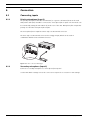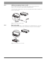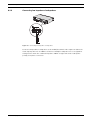
1
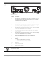
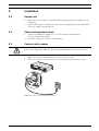
Plena Mixer Amplifier
PLE-1MExx0-xx
en
Installation and Operation manual
Plena Mixer Amplifier
Table of Contents | en
3
Table of Contents
1
Safety
5
2
Short Information
8
2.1
Purpose
8
2.2
Digital document
8
2.3
Intended audience
8
2.4
Related documentation
8
2.5
Alerts and notice signs
8
2.6
Conversion tables
9
3
System Overview
10
3.1
The Plena product range
10
3.2
Contents of box
10
3.3
The Plena Mixer Amplifier
11
3.4
Controls, connectors and indicators
12
3.4.1
Front panel
12
3.4.2
Back panel
13
4
Planning
14
5
Installation
15
5.1
Unpack unit
15
5.2
Check settings/connections
15
5.3
Connect unit to mains
15
6
Connection
16
6.1
Connecting inputs
16
6.1.1
Priority microphone (input 1)
16
6.1.2
Secondary microphone (input 2)
16
6.1.3
Additional microphones (inputs 3 and 4)
17
6.1.4
Music source input
17
6.2
Connecting outputs
18
6.2.1
Main output
18
6.2.2
Call only
18
6.2.3
Connecting constant voltage loudspeakers
18
6.2.4
Connecting low impedance loudspeakers
19
7
Configuration
20
7.1
Unit settings
20
7.1.1
Rear panel settings
20
7.1.2
Pin settings and labeling
20
8
Operation
21
8.1
Switch on and off
21
Bosch Security Systems B.V.
Installation and Operation manual
PLE-1MExx0-xx | V1.0 | 2011.04
4
en | Table of Contents
Plena Mixer Amplifier
8.1.1
Switch on
21
8.1.2
Switch off
21
8.2
Microphone/line controls
21
8.3
Music controls
21
8.3.1
Volume control
21
8.3.2
Tone control
21
8.4
Output controls
21
8.4.1
Master volume control
21
9
Maintenance
22
10
Technical Data
23
10.1
Electrical
23
10.1.1
Mains power supply
23
10.1.2
Power consumption
23
10.1.3
Performance
23
10.1.4
Mic./Line input 4 x
23
10.1.5
Music input
24
10.1.6
Loudspeaker output 100 V / 70 V
24
10.1.7
Loudspeaker output 4 Ohm
24
10.2
Mechanical
24
10.3
Environmental
24
PLE-1MExx0-xx | V1.0 | 2011.04
Installation and Operation manual
Bosch Security Systems B.V.
Plena Mixer Amplifier
1
Safety | en
5
Safety
Before installing or operating this product, always read the Safety Instructions, which are
available as a separate document (9922 141 7014x). These instructions are supplied together
with all equipment that can be connected to the mains.
Alerts on the appliance:
This symbol found on the apparatus indicates hazards arising from dangerous voltages.
This symbol found on the apparatus indicates the user should read all safety statements
foundin the operating instructions.
This symbol found on the apparatus indicates double insulation.
Warning
To reduce the risk of fire or electrical shock, do not expose this apparatus to rain or moisture.
This symbol found on the apparatus indicates that the apparatus must be placed in a
separatecollection facility for electronic waste and not disposed with household waste.
–
Read instructions - All the safety instructions for use should be read before the system is
operated.
–
Retain instructions - The safety instructions and operating instructions should be
retained for future reference.
–
Heed warnings - All warnings on the unit and in the operating instructions should be
adhered to.
–
Follow instructions - All operating instructions and instructions for use should be
followed.
–
Cleaning - Unplug system units from the mains outlet before cleaning. Do not use liquid
cleaners or aerosol cleaners. Use only a dry cloth for cleaning.
–
Attachments - Do not use attachments not recommended by the product manufacturer as
they may cause hazards.
–
Water and Moisture - Do not use this unit near water, for example near a bathtub,
washbowl, kitchen sink, or laundry basket, in a wet basement, near a swimming pool, in
an unprotected outdoor installation or any area which is classified as a wet location.
–
Accessories - Do not place this unit on an unstable stand, tripod, bracket or mount. This
unit may fall, causing serious injury to a person and serious damage to the unit. Use only
a stand, tripod, bracket or mount recommended by the manufacturer, or sold with the
Bosch Security Systems B.V.
Installation and Operation manual
PLE-1MExx0-xx | V1.0 | 2011.04
6
en | Safety
Plena Mixer Amplifier
product. Any mounting of the unit should follow the manufacturer's instructions, and
should use a mounting accessory recommended by the manufacturer. An appliance and
cart combination should be moved with care. Quick stops, excessive force, and uneven
surfaces may cause the appliance and cart combination to overturn.
–
Ventilation - Openings in the enclosure, if any, are provided for ventilation and to ensure
reliable operation of the unit and to protect it from overheating. These openings must not
be blocked or covered. The unit should not be placed in a built-in installation unless
proper ventilation is provided or the manufacturer's instructions have been adhered to.
Maintain a minimum distance of 2 inch (50 mm) around the front, the rear, and the sides
of the unit for sufficient ventilation.
–
Heat sources - Do not install the unit near any heat sources such as radiators, stoves, or
other apparatus that produce heat (including amplifiers).
–
Open flames - No open flames, such as lighted candles, should be placed on the unit.
–
Power sources - Units should be operated only from the type of power source indicated
on the marking label. If you are not sure of the type of power supply you plan to use,
consult your appliance dealer or local power company. For units intended to operate
from battery power, or other sources, refer to the "Installation and User Instructions".
–
Grounding or polarisation - This unit may be equipped with a polarised alternating
current line plug (a plug having one blade wider than the other). This plug will fit into the
power outlet only one way. This is a safety feature. If you are unable to insert the plug
fully into the outlet, try reversing the plug. If the plug still fails to fit, contact your
electrician to replace your obsolete outlet. Do not defeat the safety purpose of the
polarised plug. Alternatively, this unit may be equipped with a 3-wire grounding type plug
having a third (grounding) pin. This plug will only fit into a grounding-type power outlet.
This is a safety feature. If you are unable to insert the plug into the outlet, contact your
electrician to replace your obsolete outlet. Do not defeat the safety purpose of the
grounding-type lug.
–
Power-Cord Protection - Power supply cords should be routed so that they are not likely
to be walked on or pinched by items placed upon or against them, paying particular
attention to cords and plugs, convenience receptacles, and the point where they exit
from the appliance.
–
Overloading - Do not overload outlets and extension cords as this can result in a risk of
fire or electrical shock.
–
Object and Liquid Entry - Never push objects of any kind into this unit through openings
as they may touch dangerous voltage points or short-out parts that could result in a fire
or electric shock. Never spill liquid of any kind on the unit.
–
Servicing - Do not attempt to service this unit yourself as opening or removing covers may
expose to dangerous voltage or other hazards. Refer all servicing to qualified service
personnel.
–
Damage Requiring Service - Unplug the unit from the outlet and refer servicing to
qualified service personnel under the following conditions:
–
When the power-supply cord or plug is damaged.
–
If liquid has been spilled, or objects have fallen into the unit.
–
If the unit has been exposed to rain or water.
–
If the unit does not operate normally by following the instructions for use. Adjust
only those controls that are covered by the instructions for use, as an improper
PLE-1MExx0-xx | V1.0 | 2011.04
Installation and Operation manual
Bosch Security Systems B.V.
Plena Mixer Amplifier
Safety | en
7
adjustment of other controls may result in damage and will often require extensive
work by a qualified technician to restore the units to their normal operation.
–
If the unit has been dropped or the unit has been damaged.
–
When the unit exhibits a distinct change in performance; this indicates a need for
service.
–
Replacement Parts - When replacement parts are required be sure the service technician
has used replacement parts specified by the manufacturer or parts which have the same
characteristics as the original part. Unauthorised substitutions may result in fire, electric
shock or other hazards.
–
Safety Check - Upon completion of any service or repairs to the units, ask the service
technician to perform safety checks to determine that the unit is in proper operating
condition.
–
Lightning - For added protection of the units during a lightning storm, or when it is left
unattended and unused for long periods of time, unplug it from the wall outlet and
disconnect the cable system. This will prevent damage to the unit due to lightning and
power-line surges.
–
Disconnection - To completely disconnect this unit from the AC mains, disconnect the
power supply cord plug from the AC receptacle. The mains plug of the power supply cord
shall remain readily operable to be able to disconnect power from the unit.
–
Before installing or operating this product, always read the Safety Instructions, which are
available as a separate document (9922 141 7014x). These instructions are supplied
together with all equipment that can be connected to the mains.
NOTICE!
American users:
This equipment has been tested and found to comply with the limits for a Class B digital
device, pursuant to part 15 of the FCC rules. These limits are designed to provide reasonable
protection against harmful interference in a residential installation. This equipment generates,
uses, and can radiate radio frequency energy and, if not installed and used in accordance with
the instructions, may cause harmful interference to radio communications. However, there is
no guarantee that interference will not occur in a particular installation.
If this equipment does cause harmful interference to radio or television reception, which can
be determined by turning the equipment OFF and ON, the user is encouraged to try to correct
the interference by one or more of the following measures:
–
Reorient or relocate the receiving antenna.
–
Increase the separation between the equipment and the receiver.
–
Connect the equipment into an outlet on a circuit different from that to which the
–
Consult the dealer or an experienced radio/TV technician for help.
receiver is connected.
NOTICE!
Canadian users:
This Class B digital device complies with Canadian ICES-003.Cet appareil numérique de classe
B est conforme à la norme NMB-003 du Canada.
Bosch Security Systems B.V.
Installation and Operation manual
PLE-1MExx0-xx | V1.0 | 2011.04
8
en | Short Information
Plena Mixer Amplifier
2
Short Information
2.1
Purpose
The purpose of this manual is to provide information required for installing, configuring and
operating a Plena Mixer Amplifier.
2.2
Digital document
These installation and user Instructions are also available as a digital document in the Adobe
Portable Document Format (PDF).
2.3
Intended audience
These Installation and User Instructions are intended for installers and users of a Plena
system.
2.4
Related documentation
The following related documents are available:
–
2.5
Safety Instructions (9922 141 1036x)
Alerts and notice signs
Three types of alerts are used in this manual. The alert type is closely related to the effect that
may be caused if it is not observed. These alerts- from least severe effect to most severe
effect - are:
CAUTION!
The equipment or the property can be damaged, or persons can be lightly injured if the alert is
not observed.
WARNING!
The equipment or the property can be seriously damaged, or persons can be severely injured
if the alert is not observed.
DANGER!
Not observing the alert will lead to death or sever injuries.
NOTICE!
Alert containing additional information. Usually, not observing a ‘notice’ does not result in
damage to the equipment or personal injuries.
PLE-1MExx0-xx | V1.0 | 2011.04
Installation and Operation manual
Bosch Security Systems B.V.
Plena Mixer Amplifier
2.6
Short Information | en
9
Conversion tables
In this manual, SI units are used to express lengths, masses, temperatures etc. These can be
converted to non-metric units using the following information.
Imperial
Metric
Metric
Imperial
1 in =
25.4 mm
1 mm =
0.03937 in
1 in =
2.54 cm
1 cm =
0.3937 in
1 ft =
0.3048 m
1m=
3.281 ft
1 mi =
1.609 km
1 km
0.622 mi
Table 2.1 Conversion of units of length
Imperial
Metric
Metric
Imperial
1 lb =
0.4536 kg
1 kg =
2.2046 lb
Table 2.2 Conversion of units of mass
Imperial
Metric
Metric
Imperial
1 psi =
68.95 hPa
1 hPa =
0.0145 psi
Table 2.3 Conversion of units of pressure
NOTICE!
1 hPa = 1mbar.
Fahrenheit
Celsius
°F = 9/5 (°C + 32)
°C = 5/9 (°F - 32)
Table 2.4 Conversion of units of temperature
Bosch Security Systems B.V.
Installation and Operation manual
PLE-1MExx0-xx | V1.0 | 2011.04
10
en | System Overview
Plena Mixer Amplifier
3
System Overview
3.1
The Plena product range
The Plena Mixer Amplifier is part of the Plena product range. Plena provides public address
solutions for places where people gather to work, worship, trade, or relax. It is a family of
system elements that are combined to create public address systems tailored for virtually any
application.
The Plena product range includes:
–
mixers
–
preamplifiers
–
power amplifiers
–
a music source unit
–
a digital message manager
–
a feedback suppressor
–
call stations
–
an All-in-One system
–
a voice alarm system
–
a timer
–
a charger
–
a loop amplifier
The various elements are designed to complement each other thanks to matched acoustical,
electrical and mechanical specifications.
3.2
Contents of box
The packaging box contains the following contents:
–
PLE-1MExx0-xx
–
Labels and colored pins for indicating favorite settings
–
Power cord
–
Plena Bonus CD
NOTICE!
The PLE-1MExx0-EU has a 100 V loudspeaker output and PLE-1MExx0-US has a 70 V
loudspeaker output.
PLE-1MExx0-xx | V1.0 | 2011.04
Installation and Operation manual
Bosch Security Systems B.V.
Plena Mixer Amplifier
3.3
System Overview | en
11
The Plena Mixer Amplifier
The Plena Mixer Amplifier is a high performance, professional public address unit for mixing
up to four separate microphone/line signals, and one music signal.
The volume of each microphone/line signal can be individually adjusted to obtain the required
mix; the mixed output is controlled via the master volume control and separate high/low tone
controls. The unit is easy to use, and provides a crisp call or clear music. The amplifier also
has enhanced features such as priority, labeling, and setting indicators.
All Microphone/line inputs can be switched between microphone level and line level
sensitivity. The inputs are balanced but can also be used unbalanced. Phantom power can be
selected via a DIP switch to provide power to condenser microphones. Input channel 1 can
take priority over all other microphone and music input:
–
Input 1 can be activated by contact closure on a PTT (push to talk). A chime can be
configured to precede an announcement.
Users can create a custom label for inputs and music sources. The label can be attached to
the special holder at the front of the mixer amplifier. Colored pins can also be inserted at
various positions around the volume and tone dial controls to indicate favorite settings for a
particular application.
An LED meter monitors the master output before the zone selection. This signal is also
present on the headphone connector below the output meter. For total reliability and ease of
use, a limiter is integrated into the output stage to restrict output if the user applies too much
signal.
Bosch Security Systems B.V.
Installation and Operation manual
PLE-1MExx0-xx | V1.0 | 2011.04
12
en | System Overview
Plena Mixer Amplifier
3.4
Controls, connectors and indicators
3.4.1
Front panel
1
2
10
9
3
8
4
7
5
6
Figure 3.1 Front panel
Number
Description
1
Power button
2
Label holder for user-defined description of microphone/line inputs custom labels can be created by user
3
High tone control
4
Master volume control
5
Output level meter (-18 db, 0 db)
6
Headphone socket
7
Low tone control
8
Music source volume control (input 5)
9
Input level control
10
–
microphone/line 1
–
microphone/line 2
–
microphone/line 3
–
microphone/line 4
Air inlet holes
NOTICE!
Do not obstruct the airflow into the unit.
PLE-1MExx0-xx | V1.0 | 2011.04
Installation and Operation manual
Bosch Security Systems B.V.
Plena Mixer Amplifier
3.4.2
System Overview | en
13
Back panel
1
2
3
4
5
6
7
8
9
10 11 12
Figure 3.2 Back panel
Number
Description
1
Microphone/line 1 input with trigger, Euro style screw terminal connector DIP switch settings for: chime, PTT (push to talk), mic./line, speech filter,
and phantom power (see number 2)
2
DIP switch for microphone/line 1 and microphone/line 2 (see numbers 1
and 3 respectively)
3
Microphone/line 2 input, Euro style screw terminal - DIP switch settings for
speech filter, mic./line, and phantom power (see number 2)
4
Microphone/line 3 input, 6.3 mm - 1/4" jack connector - DIP switch settings
for mic./line, and phantom power (see number 5)
5
DIP switch for microphone/line 3 and microphone/line 4 (see numbers 4
and 6 respectively)
6
Microphone/line 4 input, 6.3 mm - 1/4" jack connector - DIP switch settings
for mic./line, and phantom power (see number 5)
7
Music input, 2x RCA/cinch connectors, Stereo, summed mono
8
Cooling fan (PLE-1ME120 & PLE-1ME240)
9
Outputs:
–
Call only, screw terminal connector 100 V
–
Screw terminal connector 100 V, and 4 Ohm
10
Mains fuse
11
Earth connection screw
12
Mains connector (3-pole)
NOTICE!
The unit must be earthed.
Always allow adequate space at the rear of the unit for ventilation.
Bosch Security Systems B.V.
Installation and Operation manual
PLE-1MExx0-xx | V1.0 | 2011.04
14
4
en | Planning
Plena Mixer Amplifier
Planning
Calculate your total power needs based on the sum of the power handling capacity and
tapping of all loudspeakers planned in your system. When you use the volume controls,
assume the maximal setting for this calculation.
Make sure that the unit has sufficient air around it for ventilation. For units with a fan, make
sure that the cabinet where the unit is placed in can evict air from the rear. For units without
a fan, leave room on top of the unit for convection. Units with a fan do not need free space
directly above the housing. Take at least 10 cm into account for connectors and wiring. Make
sure that no liquids can spill into or on the unit and that the air intake holes are not
obstructed. Make sure that there is a power outlet of sufficient rating close to the intended
location.
PLE-1MExx0-xx | V1.0 | 2011.04
Installation and Operation manual
Bosch Security Systems B.V.
Plena Mixer Amplifier
Installation | en
5
Installation
5.1
Unpack unit
1.
15
Remove the unit from the box, and discard the packaging material according to local
regulations.
2.
Use your fingernails to carefully peel off the protective plastic film from the label holders.
Do not use sharp or pointed objects.
5.2
Check settings/connections
1.
Connect any additional equipment (see Section 6.1 Connecting inputs and
Section 6.2 Connecting outputs).
2.
5.3
Check the settings (see Section 7.1 Unit settings).
Connect unit to mains
CAUTION!
Before connecting power, always check the voltage indicator plate at the rear of the unit.
1.
Make sure the power switch on the front of the unit is set to Off.
2.
Connect the power cord to the mains connector and plug it into the mains outlet.
Figure 5.1 Power connection and voltage selector
Bosch Security Systems B.V.
Installation and Operation manual
PLE-1MExx0-xx | V1.0 | 2011.04
16
en | Connection
Plena Mixer Amplifier
6
Connection
6.1
Connecting inputs
6.1.1
Priority microphone (input 1)
The priority microphone PLE-1CS or PLE-1SCS (or a generic call station) that can be used
with push to talk (PTT) should be connected to “microphone/line 1 input”. The PTT mode can
be activated by setting the DIP switch (2) at the rear of the unit. Microphone/line 1 input has
priority over all other microphone/line inputs.
The microphone/line 1 input has a Euro style screw terminal connector.
The Euro style screw terminal connector has a trigger input, which can be used in
combination with the Euro and XLR connector.
Figure 6.1 Euro connector with trigger
6.1.2
Secondary microphone (input 2)
Connect a secondary microphone to “microphone/line input 2”.
Set the DIP switch settings next to the connector as required. See Section 7.1 Unit settings.
PLE-1MExx0-xx | V1.0 | 2011.04
Installation and Operation manual
Bosch Security Systems B.V.
Plena Mixer Amplifier
6.1.3
Connection | en
17
Additional microphones (inputs 3 and 4)
Connect additional microphones to microphone/line inputs 3 and 4 as required. See
Figure 6.2. These microphones will mix with the background music.
Set the DIP switch settings between connector for microphone/lines 3 and 4, as required. See
Section 7.1 Unit settings.
Figure 6.2 Connecting microphone inputs
6.1.4
Music source input
When using a CD player, tuner or other auxiliary device for background music, connect the
line-out connectors of the music source to the line-in connectors of the mixer amplifier.
Figure 6.3 Connecting music source inputs
Bosch Security Systems B.V.
Installation and Operation manual
PLE-1MExx0-xx | V1.0 | 2011.04
18
en | Connection
Plena Mixer Amplifier
6.2
Connecting outputs
6.2.1
Main output
Connect speakers to the 100 V, 70 V or 4 Ohm terminal on the Euro style screw terminal
connector (9) at the rear of the unit.
Also see Section 6.2.3 Connecting constant voltage loudspeakers and Section 6.2.4 Connecting
low impedance loudspeakers.
6.2.2
Call only
Connect speakers to the 100 V terminal on the Euro style screw terminal connector (9) at the
rear of the unit.
Also see Section 6.2.3 Connecting constant voltage loudspeakers and Section 6.2.4 Connecting
low impedance loudspeakers.
6.2.3
Connecting constant voltage loudspeakers
Figure 6.4 Connecting constant voltage loudspeakers
The mixer amplifier can drive 100 V constant voltage loudspeakers.
Connect the loudspeakers in parallel and check the loudspeaker polarity for in-phase
connection. The summed loudspeaker power should not exceed the rated amplifier output
power.
You can use the Call Only output for 3-wire remote volume control override. You can also use
this output as an extra zone where announcements can be heard, but not music.
PLE-1MExx0-xx | V1.0 | 2011.04
Installation and Operation manual
Bosch Security Systems B.V.
Plena Mixer Amplifier
6.2.4
Connection | en
19
Connecting low impedance loudspeakers
Figure 6.5 Connecting low impedance loudspeakers
Connect low impedance loudspeakers to the 4 Ohm/0 terminals. This output can deliver the
rated output power into an 4 Ohm load. Connect multiple loudspeakers in a series/parallelarrangement to make the combined impedance 4 Ohm or higher. Check the loudspeaker
polarity for in-phase connection.
Bosch Security Systems B.V.
Installation and Operation manual
PLE-1MExx0-xx | V1.0 | 2011.04
20
en | Configuration
Plena Mixer Amplifier
7
Configuration
7.1
Unit settings
7.1.1
Rear panel settings
The unit can be quickly set-up for operation by setting the following controls at the rear of the
unit:
–
7.1.2
DIP switches
Pin settings and labeling
Users can create custom labels for the: microphone/line inputs, description of the music
source. These labels can be attached to the mixer amplifier at position number 2 (see
Figure 3.1). Colored pins can also be inserted at various positions around the dial controls to
indicate the favorite settings for a particular application.
The pins are engineered in such a way that they cannot be taken out by hand. This is to
prevent tampering. The pins are intended to be inserted once, during installation of the unit.
The silver pins should be used to indicate the preferred settings of the unit. The red pins can
optionally be used to indicate the maximum setting of a knob.
If these settings have to be changed, use a pair of soft-tipped pliers to carefully remove the
pins. If you do not have a pair of soft-tipped pliers, you can use ordinary pliers instead, but
first place some plastic tape on the tips of the pliers to prevent damaging the front of the unit.
To remove the clear plastic covers in front of the labels:
1.
Carefully insert a small screwdriver into the cut-out at the bottom of the plastic cover.
2.
Gently lift the cover, and bend it in the middle. Take care not to force the cover or the
front panel.
To reattach the plastic covers with paper labels:
1.
Insert the paper label into the holder at the front of the unit.
2.
Pick up the cover, and then bend it slightly in the middle by hand.
3.
Fit the cover into the slot at the front of the unit, and then gently release the cover,
making sure that the paper label stays in place.
PLE-1MExx0-xx | V1.0 | 2011.04
Installation and Operation manual
Bosch Security Systems B.V.
Plena Mixer Amplifier
Operation | en
8
Operation
8.1
Switch on and off
8.1.1
Switch on
21
CAUTION!
Before applying power, always check the voltage indicator plate at the rear of the unit.
1.
8.1.2
Set the power button (1) on the front of the unit to On - pushed in (see Figure 8.1).
Switch off
1.
Set the power button (1) on the front of the unit to Off - popped out (see Figure 8.1).
1
2
10
9
3
8
4
7
5
6
Figure 8.1 Front panel
8.2
Microphone/line controls
Use the volume controls (9) to individually control the sound level of microphone/line inputs 1
through 4.
8.3
Music controls
8.3.1
Volume control
Use the music source volume control (8) to control the sound level of the selected music
source.
8.3.2
Tone control
The tone controls are not standard bass and treble controls: they can be used as a traditional
tone control with high and low control.
The tone control for the low frequencies boosts deep bass first without making the sound
boomy, and cuts rumble without loosing warmth in the low frequencies.
Use the Hi (high) and Lo (low) tone controls (see Figure 8.1, numbers 3 and 7) to change the
tone.
8.4
Output controls
8.4.1
Master volume control
Use the master volume control dial (4) to collectively control the sound level of all outputs,
except the emergency announcement/signal.
Bosch Security Systems B.V.
Installation and Operation manual
PLE-1MExx0-xx | V1.0 | 2011.04
22
9
en | Maintenance
Plena Mixer Amplifier
Maintenance
The mixer amplifier has been designed to function without problems for a long time with a
minimum of maintenance.
In order to guarantee trouble-free operation, clean the unit with a damp lint free cloth,
especially the air intake holes on the front. Have a technician clean the dust from the fan and
the inside at regular intervals for the models that have a fan. Base the interval on the actual
situation and dust build up, start with an interval of at least once per year. Periodically check
the connectors for corrosion and check the screw terminals to make sure that they have not
become loosened.
PLE-1MExx0-xx | V1.0 | 2011.04
Installation and Operation manual
Bosch Security Systems B.V.
Plena Mixer Amplifier
Technical Data | en
10
Technical Data
10.1
Electrical
10.1.1
Mains power supply
Voltage PLE-1MEXX0-EU:
230 VAC, ±10%, 50/60 Hz
Voltage PLE-1MEXX0-US:
120 VAC, ±10%, 50/60 Hz
23
(reduced power at lower mains)
(reduced power at lower mains)
10.1.2
10.1.3
Inrush Current PLE-1ME060-EU:
5A
Inrush Current PLE-1ME060-US:
10 A
Inrush Current PLE-1ME120-EU:
10 A
Inrush Current PLE-1ME120-US:
20 A
Inrush Current PLE-1ME240-EU:
12 A
Inrush Current PLE-1ME240-US:
24 A
Power consumption
PLE-1ME060-XX:
200 VA
PLE-1ME120-XX:
400 VA
PLE-1ME240-XX:
800 VA
Performance
Frequency response:
Line 60 Hz to 20 kHz
(+1/-3 dB @ 10 dB ref. rated output)
Mic. 70 Hz to 20 kHz
(+1/-3 dB @ 10 dB ref. rated output)
10.1.4
Distortion:
<1% @ rated output power, 1 kHz
Bass control:
Max. -10/+10 dB
Treble control:
Max. -10/+10 dB
Mic./Line input 4 x
Input 1 (Push-to-talk contact
5-pin Euro style, balanced, phantom
with priority):
Input 2:
3-pin Euro style, balanced, phantom
Input 3 & 4:
TRS Jack (1/4, 6.3 mm), balanced
Sensitivity:
1 mV (mic); 300 mV (line)
Impedance:
>1 kOhm (mic); >5 kOhm (line)
Dynamic range:
93 dB
S/N (flat at max. volume):
>63 dB (mic); >70 dB (line)
S/N (flat at min. volume/muted): >75 dB
CMRR (mic.):
>40 dB (50 Hz to 20 kHz)
Headroom:
>17 dB
Speech filter:
-3 dB @ 315 Hz, high-pass, 6 dB/oct
Phantom power supply
16 V via 1.2 kOhm (mic)
Bosch Security Systems B.V.
Installation and Operation manual
PLE-1MExx0-xx | V1.0 | 2011.04
24
en | Technical Data
10.1.5
Plena Mixer Amplifier
Music input
Connector:
Cinch, stereo converted to mono
Sensitivity:
200 mV
Impedance:
22 kOhm
S/N (flat at max. volume):
>75 dB
S/N (flat at min. volume/muted): >80 dB
Headroom:
10.1.6
10.1.7
10.2
10.3
>25 dB
Loudspeaker output 100 V / 70 V
Connector:
Screw terminal, floating
Max. / rated PLE-1ME060-XX:
90 W / 60 W
Max. / rated PLE-1ME120-XX:
180 W / 120 W
Max. / rated PLE-1ME240-XX:
360 W / 240 W
Loudspeaker output 4 Ohm
Connector:
Screw terminal, floating
Max. / rated PLE-1ME060-XX:
15.5 V (60 W)
Max. / rated PLE-1ME120-XX:
22 V (120 W)
Max. / rated PLE-1ME240-XX:
31 V (240 W)
Mechanical
Dimensions (H x W x D):
100 x 430 x 270 mm (19" wide, 2U high)
Mounting:
Stand-alone, 19" rack
Color:
Charcoal
Weight (PLE-1ME060-EU):
Approx. 6.5 kg
Weight (PLE-1ME120-EU):
Approx. 8.9 kg
Weight (PLE-1ME240-EU):
Approx. 10.5 kg
Environmental
Operating temperature:
-10 °C to +45 °C
Storage temperature:
-40 °C to +70 °C
Relative humidity:
<95%
Acoustic noise level of fan
<33 dB SPL @ 1 m
(PLE-1ME240-EU):
PLE-1MExx0-xx | V1.0 | 2011.04
Installation and Operation manual
Bosch Security Systems B.V.
Bosch Security Systems B.V.
Kapittelweg 10
4800 RA Breda
The Netherlands
www.boschsecurity.com
© Bosch Security Systems B.V., 2011