1
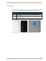
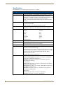
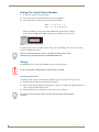
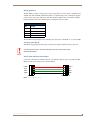
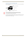
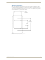
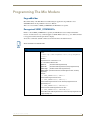
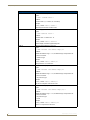
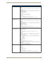
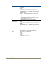
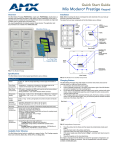
Operation/Reference Guide
Mio Modero
®
Device Family
Control System Accessories
Last Revised: 09/05/2008
AMX Limited Warranty and Disclaimer
AMX warrants its products to be free of defects in material and workmanship under normal use for three (3) years from
the date of purchase from AMX, with the following exceptions:
•
Electroluminescent and LCD Control Panels are warranted for three (3) years, except for the display and touch
overlay components that are warranted for a period of one (1) year.
•
Disk drive mechanisms, pan/tilt heads, power supplies, and MX Series products are warranted for a period of one
(1) year.
•
AMX Lighting products are guaranteed to switch on and off any load that is properly connected to our lighting
products, as long as the AMX Lighting products are under warranty. AMX does guarantee the control of dimmable
loads that are properly connected to our lighting products. The dimming performance or quality cannot be
guaranteed due to the random combinations of dimmers, lamps and ballasts or transformers.
•
Unless otherwise specified, OEM and custom products are warranted for a period of one (1) year.
•
AMX Software is warranted for a period of ninety (90) days.
•
Batteries and incandescent lamps are not covered under the warranty.
This warranty extends only to products purchased directly from AMX or an Authorized AMX Dealer.
All products returned to AMX require a Return Material Authorization (RMA) number. The RMA number is obtained
from the AMX RMA Department. The RMA number must be clearly marked on the outside of each box. The RMA is
valid for a 30-day period. After the 30-day period the RMA will be cancelled. Any shipments received not consistent
with the RMA, or after the RMA is cancelled, will be refused. AMX is not responsible for products returned without a
valid RMA number.
AMX is not liable for any damages caused by its products or for the failure of its products to perform. This includes any
lost profits, lost savings, incidental damages, or consequential damages. AMX is not liable for any claim made by a
third party or by an AMX Dealer for a third party.
This limitation of liability applies whether damages are sought, or a claim is made, under this warranty or as a tort claim
(including negligence and strict product liability), a contract claim, or any other claim. This limitation of liability cannot
be waived or amended by any person. This limitation of liability will be effective even if AMX or an authorized
representative of AMX has been advised of the possibility of any such damages. This limitation of liability, however, will
not apply to claims for personal injury.
Some states do not allow a limitation of how long an implied warranty last. Some states do not allow the limitation or
exclusion of incidental or consequential damages for consumer products. In such states, the limitation or exclusion of
the Limited Warranty may not apply. This Limited Warranty gives the owner specific legal rights. The owner may also
have other rights that vary from state to state. The owner is advised to consult applicable state laws for full
determination of rights.
EXCEPT AS EXPRESSLY SET FORTH IN THIS WARRANTY, AMX MAKES NO OTHER WARRANTIES,
EXPRESSED OR IMPLIED, INCLUDING ANY IMPLIED WARRANTIES OF MERCHANTABILITY OR FITNESS FOR
A PARTICULAR PURPOSE. AMX EXPRESSLY DISCLAIMS ALL WARRANTIES NOT STATED IN THIS LIMITED
WARRANTY. ANY IMPLIED WARRANTIES THAT MAY BE IMPOSED BY LAW ARE LIMITED TO THE TERMS OF
THIS LIMITED WARRANTY.
Software License and Warranty Agreement
LICENSE GRANT.
AMX grants to Licensee the non-exclusive right to use the AMX Software in the manner described in this License. The AMX Software is
licensed, not sold. This license does not grant Licensee the right to create derivative works of the AMX Software. The AMX Software consists
of generally available programming and development software, product documentation, sample applications, tools and utilities, and
miscellaneous technical information. Please refer to the README.TXT file on the compact disc or download for further information regarding
the components of the AMX Software. The AMX Software is subject to restrictions on distribution described in this License Agreement.
LICENSEE MAY NOT SUBLICENSE, RENT, OR LEASE THE AMX SOFTWARE. Licensee may not reverse engineer, decompile, or
disassemble the AMX Software.
INTELLECTUAL PROPERTY.
The AMX Software is owned by AMX and is protected by United States copyright laws, patent laws, international treaty provisions, and/or state
of Texas trade secret laws. Licensee may make copies of the AMX Software solely for backup or archival purposes. Licensee may not copy
the written materials accompanying the AMX Software.
TERMINATION.
AMX RESERVES THE RIGHT, IN ITS SOLE DISCRETION, TO TERMINATE THIS LICENSE FOR ANY REASON AND UPON WRITTEN
NOTICE TO LICENSEE. In the event that AMX terminates this License, the Licensee shall return or destroy all originals and copies of the
AMX Software to AMX and certify in writing that all originals and copies have been returned or destroyed.
PRE-RELEASE CODE.
Portions of the AMX Software may, from time to time, as identified in the AMX Software, include PRE-RELEASE CODE and such
code may not be at the level of performance, compatibility and functionality of the final code. The PRE-RELEASE CODE may not
operate correctly and may be substantially modified prior to final release or certain features may not be generally released. AMX is
not obligated to make or support any PRE-RELEASE CODE. ALL PRE-RELEASE CODE IS PROVIDED "AS IS" WITH NO
WARRANTIES.
LIMITED WARRANTY.
AMX warrants that the AMX Software will perform substantially in accordance with the accompanying written materials for a period of ninety
(90) days from the date of receipt. AMX DISCLAIMS ALL OTHER WARRANTIES, EITHER EXPRESS OR IMPLIED, INCLUDING, BUT NOT
LIMITED TO IMPLIED WARRANTIES OF MERCHANTABILITY AND FITNESS FOR A PARTICULAR PURPOSE, WITH REGARD TO THE
AMX SOFTWARE. THIS LIMITED WARRANTY GIVES LICENSEE SPECIFIC LEGAL RIGHTS. Any supplements or updates to the AMX
SOFTWARE, including without limitation, any (if any) service packs or hot fixes provided to Licensee after the expiration of the ninety (90) day
Limited Warranty period are not covered by any warranty or condition, express, implied or statutory.
LICENSEE REMEDIES.
AMX's entire liability and Licensee's exclusive remedy shall be repair or replacement of the AMX Software that does not meet AMX's Limited
Warranty and which is returned to AMX. This Limited Warranty is void if failure of the AMX Software has resulted from accident, abuse, or
misapplication. Any replacement AMX Software will be warranted for the remainder of the original warranty period or thirty (30) days,
whichever is longer. Outside the United States, these remedies may not available.
NO LIABILITY FOR CONSEQUENTIAL DAMAGES. IN NO EVENT SHALL AMX BE LIABLE FOR ANY DAMAGES WHATSOEVER
(INCLUDING, WITHOUT LIMITATION, DAMAGES FOR LOSS OF BUSINESS PROFITS, BUSINESS INTERRUPTION, LOSS OF BUSINESS
INFORMATION, OR ANY OTHER PECUNIARY LOSS) ARISING OUT OF THE USE OF OR INABILITY TO USE THIS AMX SOFTWARE,
EVEN IF AMX HAS BEEN ADVISED OF THE POSSIBILITY OF SUCH DAMAGES. BECAUSE SOME STATES/COUNTRIES DO NOT
ALLOW THE EXCLUSION OR LIMITATION OF LIABILITY FOR CONSEQUENTIAL OR INCIDENTAL DAMAGES, THE ABOVE LIMITATION
MAY NOT APPLY TO LICENSEE.
U.S. GOVERNMENT RESTRICTED RIGHTS.
The AMX Software is provided with RESTRICTED RIGHTS. Use, duplication, or disclosure by the Government is subject to
restrictions as set forth in subparagraph ©(1)(ii) of The Rights in Technical Data and Computer Software clause at DFARS 252.2277013 or subparagraphs ©(1) and (2) of the Commercial Computer Software Restricted Rights at 48 CFR 52.227-19, as applicable.
SOFTWARE AND OTHER MATERIALS FROM AMX.COM MAY BE SUBJECT TO EXPORT CONTROL.
The United States Export Control laws prohibit the export of certain technical data and software to certain territories. No software from this Site
may be downloaded or exported (i) into (or to a national or resident of) Cuba, Iraq, Libya, North Korea, Iran, Syria, or any other country to
which the United States has embargoed goods; or (ii) anyone on the United States Treasury Department's list of Specially Designated Nationals or the U.S. Commerce Department's Table of Deny Orders. AMX does not authorize the downloading or exporting of any software or
technical data from this site to any jurisdiction prohibited by the United States Export Laws.
This Agreement replaces and supersedes all previous AMX Software License Agreements and is governed by the laws of the State of Texas,
and all disputes will be resolved in the courts in Collin County, Texas, USA. For any questions concerning this Agreement, or to contact AMX
for any reason, please write: AMX, 3000 Research Drive, Richardson, TX 75082.
Table of Contents
Table of Contents
Overview ............................................................................................................1
Specifications............................................................................................................ 2
Available Color Schemes........................................................................................... 3
Mio Modero LCD Feature ......................................................................................... 3
Fixed Menu System ......................................................................................................... 3
Proximity Detection "People Sensor"....................................................................... 3
Installation ..........................................................................................................5
Changing Buttons ..................................................................................................... 6
To switch out "installation" buttons:............................................................................... 6
To change custom buttons: ............................................................................................. 7
Mio Modero Prestige ...................................................................................................... 7
Setting The AxLink Device Number .......................................................................... 8
Wiring ....................................................................................................................... 8
Preparing captive wires................................................................................................... 8
Wiring guidelines ............................................................................................................ 9
Connecting the Wiring .................................................................................................... 9
AxLink Data and Power Connections .............................................................................. 9
Using AxLink for data with an auxiliary power supply................................................... 10
Mounting Procedures ............................................................................................. 11
Wallbox Mounting......................................................................................................... 12
Podium Mounting.......................................................................................................... 13
Accent Frame.......................................................................................................... 14
Mio Modero IR .................................................................................................15
Wiring and Installation ............................................................................................ 16
Setting the AxLink Device Number ............................................................................... 16
Wiring Guidelines.......................................................................................................... 17
AxLink Data and Power Connections ............................................................................ 17
Checking AxLink Status ................................................................................................. 17
Mounting Procedure ............................................................................................... 18
Programming The Mio Modero ........................................................................21
KeypadBuilder ........................................................................................................ 21
Recognized SEND_COMMANDs............................................................................. 21
Sending Firmware to The Mio Modero Keypads .................................................... 26
Mio Modero Device Family
i
Table of Contents
ii
Mio Modero Device Family
Overview
Overview
The Mio Modero device family provides a wide range of control capabilities in the form of keypads that
are as adept as they are elegant. Each device is available as single style (8 button max) or double style
(16 button max) with an optional LCD capped button. The devices are available as follows:
Mio Modero Device Family
Classic
Engraved plastic buttons with a red (active) feedback LED in the upper left corner.
Prestige
Clear plastic capped buttons with laser printed inserts; a red (active) feedback LED in the
upper left corner.
Elite
Painted and engraved plastic buttons, backlit with a blue (inactive) and red (active) feedback;
available with an LCD button.
Mio Modero IR IR receiver capable of accepting both 38kHz and 455kHz frequency bands.
FIG. 1 White, Single Style Classic; Black, Single Style Prestige; Gray, Double Style Elite with LCD
Mio Modero Device Family
1
Overview
Specifications
The Mio Modero device family keypad specifications are as follows:
Specifications
Power:
12 vDC, 70 - 230 mA (range depending on device type and number of buttons)
Front Panel Components: • LCD (where applicable) - SPI controlled 96 x 96 pixel resolution, monochrome
FSTN display with a white Electroluminescent backlight; an active button.
• Pushbuttons - a maximum of 8 buttons on the single style and 16 buttons on the
double style. The Classic and Prestige provide a direct LED light.
• LEDs - red and blue backlit buttons indicate activity. Only present in the Elite
devices.
Rear Panel Components:
• DIP switch - 8 position mini DIP switch used to set the device address for the
keypad on the AxLink Bus.
Dimensions (HWD):
• Single style - 4.46" x 2.71" x .57" (113.28 mm x 68.83 mm x 14.48 mm)
Supported Languages:
• English
• Russian
• Spanish
• Japanese
• French
• Thai
• Italian
• Hindi
• German
• Korean
• Portuguese
• Hebrew
• Arabic
• Greek
• Wiring connection - 4 pin 3.5mm Phoenix AxLink connector.
• Double style - 4.46" x 4.39" x .57" (113.28 mm x 111.51 mm x 14.48 mm)
• Mandarin Chinese
Weight (range):
.25 lbs (.11 kg) - .50 lbs (.23 kg)
Operating Environment:
• Operating Temperature: 0° to 50° C (32° to 122° F)
• Storage Temperature: -10° to 70° C (14° to 158° F)
Mounting:
Included Accessories:
Mounts into US and a majority of International single gang back boxes.
• Single style mounting kit (KA-5795-01)
• Double style mounting kit (KA-5795-02)
• Mylar kit (Prestige only) - Sheets of common menu items and icons for creating
inserts for single and double buttons. Available in either black, white, or beige.
(66-5798-01WH, White; 66-5798-01BG, Beige; 66-5798-01BL, Black)
• Phoenix Connector (41-5045)
• Installation Buttons (Elite and Classic only)
Optional Accessories:
• Accent Frame (for some larger wallboxes):
Classic and Prestige Colors (xx indicates color selection) - FG5795-08xx
(single button); FG5795-09xx (double button)
Elite Colors (xx indicates color selection) - FG5796-08xx (single button);
FG5796-09xx (double button)
• Custom buttons:
Classic Colors (xx indicats color selection) - FG5795-21xx (4 single buttons);
FG5795-22xx (2 double buttons)
Prestige Colors (xx indicats color selection) - FG5798-05xx (4 single buttons);
FG5798-06xx (2 double buttons)
Elite Colors (xx indicats color selection) - FG5796-21xx (4 single buttons);
FG5796-22xx (2 double buttons)
• Blank buttons:
Classic Colors (xx indicats color selection) - FG5795-07xx
Elite Colors (xx indicats color selection) - FG5796-07xx
2
Mio Modero Device Family
Overview
Available Color Schemes
The Mio Modero device family is available in a range of colors, and the Elite supports a variety of
Lutron color schemes.
Mio Modero Color Schemes
Mio Modero Classic
Black (BL), White (WH), Beige (BG)
Mio Modero Prestige
Black (BL), White (WH), Beige (BG)
Mio Modero Elite
Black (BL), White (WH), Beige (BG), Almond (AL), Brown (BR), Gray (GR), Ivory
(IV), Light Almond (LA), Taupe (TP), Gold (GL), Silver (SL)
IR Receiver
Black (BL), White (WH), Beige (BG)
International Wall Plates Black (BL), White (WH), Beige (BG), Almond (AL), Brown (BR), Gray (GR), Ivory
(IV), Light Almond (LA), Taupe (TP), Gold (GL), Silver (SL)
Mio Modero LCD Feature
The Mio Modero Elite is available with an optional LCD screen. The LCD is a scalable black-and-white
image (SPI) controlled 96 x 96 resolution monochrome FSTN display with a white Electroluminescent
back light. The viewable area of the screen is 25 mm x 25 mm. The LCD displays an 18 pt. font and
supports 4 lines of text. The viewing angle of the LCD is 12 o’clock, allowing for a top down viewing
once mounted to a wall.
The LCD is capable of displaying levels via a bar graph and text over the bar graphs.
Additionally, the LCD has a button cap enabling it to act as a button.
Fixed Menu System
Using the KeypadBuilder application available for download from www.amx.com, the LCD can be
programmed with a Fixed Menu System (FMS) that is navigated via the Mio Modero and its LCD
button. See the KeypadBuilder Instruction Manual for more information on programming Fixed Menu
Systems.
Proximity Detection "People Sensor"
The Mio Modero Elite has an electromagnetic field proximity detector or "People Sensor." A disruption
of the field within 4 to 6 inches will activate the keypad’s backlight.
Mio Modero Device Family
3
Overview
4
Mio Modero Device Family
Installation
Installation
Before touching the device, discharge the static electricity from your body by touching
a grounded metal object.
The basic front and rear components of the Mio Modero are as follows:
Installation Button
AxLink
3.5 mini Phoenix
connector
Slot to pry
button free
PWR+
Screw
holes
8 position mini
DIP switch
Notch to pry
faceplate free
(Rear Single)
(Front Single)
8 position mini
DIP switch
AxLink
3.5 mini Phoenix
connector
Screw
holes
PWR+
Notch to pry
faceplate free
(Rear Double)
FIG. 2 Mio Modero Front and Rear Components
Mio Modero Device Family
5
Installation
Mounting
Frame
LCD
Installation Buttons
Faceplate
FIG. 3 Sections of The Mio Modero
Changing Buttons
The Mio Modero Classic and Elite are shipped with "installation" buttons; they are intended to be place
holders until your engraved buttons, designed with KeypadBuilder, arrive.
To switch out "installation" buttons:
1. Pry the button using the slot on the front of the "installation" buttons to remove them from the Mio
Modero.
2. Select the location of the custom buttons and snap them into place. Be sure to note the orientation of
the white insert on the back of the button, the notch must be down. Insert the bottom of the button
first and then push the top into place.
3. Snap the faceplate on the mounting frame.
6
Mio Modero Device Family
Installation
To change custom buttons:
1. If connected, disconnect the power supply.
2. If connected to mounting frame, place a flathead screwdriver in the notch at the bottom right of the
Mio Modero, and pry the faceplate from the mounting frame.
3. On the back of the faceplate locate the button access points, outlined with white circles. Using a
straightened paperclip, poke through the button access points until the buttons pop free.
4. Snap the desired custom buttons into place. Be sure to note the orientation of the white insert on the
back of the button, the notch must be down. Insert the bottom of the button first and then push the
top into place.
5. If the power supply was disconnected in Step 1, reconnect and return power to the device.
6. Snap the faceplate on the mounting frame.
Be certain to reprogram the Mio Modero to match the new button arrangement; use KeypadBuilder to
assign the locations. See the KeypadBuilder Instruction Manual available at www.amx.com.
Mio Modero Prestige
The Mio Modero Prestige ships with sheets of common menu items and icons for creating inserts for
single and double buttons.
1. If connected, disconnect the power supply.
2. If connected to mounting frame, place a flathead screwdriver in the notch at the bottom right of the
Mio Modero, and pry the faceplate from the mounting frame.
3. On the back of the faceplate locate the button access points, outlined with white circles. Using a
straightened paperclip, poke through the button access points until the buttons pop free.
4. The Prestige buttons are comprised of three parts, the frame, window, and back insert. From the
front of the button, use your thumb to poke the window and back insert out of the frame. See FIG. 4.
Back Insert
Window
Frame
Printed
Label
FIG. 4 Prestige Button Components
5. Snap the widow into the frame and then place the printed labels inside each
button.
6. Snap the back inset to the window and frame.
7. Insert the buttons into their proper location on the faceplate.
8. If the power supply was disconnected in Step 1, reconnect and return power to the device.
9. Snap the faceplate on the mounting frame.
Mio Modero Device Family
7
Installation
Setting The AxLink Device Number
1. If connected, disconnect the power supply.
2. Locate the 8-position Device DIP switch on the rear panel.(FIG. 5).
3. Set the DIP switch according to the switch values shown below.
Switch
1 2 3 4 5
6
7
8
Value
1 2 4 8 16 32 64 128
The device number is set by the total value of DIP switch positions that are ON (up).
As an example, the DIP switch in FIG. 5 defines device number 129 (1+128=129).
FIG. 5 Example Device DIP Switch set to 129
If you later change the device number, remove and reconnect the AxLink power connector to enter the
new device number into memory.
AMX has created Dip Switch2 to assist in calculating dip switch position values.
Download the program Dip Switch2 from www.amx.com for free.
Wiring
The Mio Modero uses a four-pin mini AxLink connector for power and data.
Do not connect power to the Mio Modero until the wiring is complete.
Preparing captive wires
You will need a wire stripper, and flat-blade screwdriver to prepare and connect the captive wires.
1. Strip 0.25 inch (6.35 mm) of wire insulation off all wires.
2. Insert each wire into the appropriate opening on the connector according to the wiring diagrams and
connector types described in this section.
3. Turn the flat-head screws clockwise to secure the wires in the connector.
Do not over-torque the screws; doing so can bend the seating pins and damage the
connector.
8
Mio Modero Device Family
Installation
Wiring guidelines
The Mio Modero requires 12 VDC power to operate properly. The necessary power is supplied via the
AxLink cable. The maximum AxLink wiring distance is determined by power consumption, supplied
voltage, and the wire gauge used for the cable. The following table lists wire sizes and the maximum
lengths allowable based on the maximum power consumption rating of 170 mA.
Wiring Guidelines at 170 mA
Wire
Size
Maximum Wiring
Length
18 AWG
690.42 feet (210.43 m)
20 AWG
436.80 feet (133.13 m)
22 AWG
272.33 feet (83.00 m)
24 AWG
171.66 feet (52.32 m)
The maximum wiring lengths for using AxLink power are based on a minimum of 13.5 volts available.
Connecting the Wiring
The following paragraphs describe wiring connections for using the AxLink and relay connectors.
If using power from AxLink, disconnect the wiring from the control system before
wiring the Mio Modero.
AxLink Data and Power Connections
Connect the control system's AxLink connector to the AxLink connector on the rear panel of the Mio
Modero for data and 12 VDC power as shown in FIG. 6.
PWR +
PWR +
AXP
AXP
AXM
AXM
GND -
GND -
Mio Modero
Control System
FIG. 6 AxLink straight-thru wiring
Mio Modero Device Family
9
Installation
Using AxLink for data with an auxiliary power supply
Connect the controller’s AxLink connector to the AxLink connector on the rear panel of the Mio Modero
device, as shown in FIG. 7.
PWR (+)
12 VDC power supply
GND (-)
PWR (+)
AXP
AXM
GND (-)
PWR (+)
AXP
AXM
GND (-)
Controller
Mio Modero device (3.5 mm connector)
FIG. 7 AxLink and 12 VDC power supply wiring diagram
If you are not using power from AxLink, disconnect the wiring from the controller
before wiring the Mio Modero device. Make sure the auxiliary power supply’s PWR
(+) is not connected to the controller’s AxLink connector.
Use an auxiliary 12 VDC power supply when the distance between the controller and server exceeds the
limits described in Wiring Guidelines table. Connect only the GND (-) wire on the AxLink connector
when using an auxiliary 12 VDC power supply.
10
Mio Modero Device Family
Installation
Mounting Procedures
FIG. 8 shows the wallbox mounting dimensions for the single and double style Mio Modero. AMX
recommends mounting the Mio Modero in a standard one-gang wallbox, a conduit box per NEC specs
section 370, with a minimum internal clearance of 2-5/8" x 1-3/4" x 1-5/8" (HWD), but it is possible to
mount the Mio Modero to a podium without a wallbox.
2.000
[50.8 MM]
3.282
[83.4 MM]
2.250
[57.2 MM]
FIG. 8 Mio Modero Single Style mounting dimensions
Mio Modero Device Family
11
Installation
2.000
[50.8 MM]
3.282
[83.4 MM]
2.250
[57.2 MM]
FIG. 9 Mio Modero Double Style mounting dimensions
Wallbox Mounting
1. Use the cutout dimension for the wallbox to cutout the install surface for the Mio Modero.
2. Confirm that the terminal end of the AxLink cable is disconnected, and not receiving power.
3. If the faceplate is connected to the mounting frame, place a flathead screwdriver in the notch at the
bottom right of the Mio Modero, and pry the faceplate from the mounting frame.
4. Connect the AxLink power supply. The connector passes through the center of the mounting frame
and connects to the board. The connection is illustrated in FIG. 2.
5. Place the mounting frame on the wallbox; align the screw holes with the mounting holes and fasten
the mounting frame to the wallbox using the screws supplied.
Do not overtighten the screws when mounting the mounting frame. The device
should be flush with mounting surface.
6. Attach the faceplate to the mounting frame first at the top and swing it to the bottom. See FIG. 10.
12
Mio Modero Device Family
Installation
FIG. 10 Attaching the faceplate to the mounting frame
Podium Mounting
1. Use the cutout dimension shown in either FIG. 8 or FIG. 9 to cutout the mounting frame install
surface for the Mio Modero.
2. Confirm that the terminal end of the AxLink cable is disconnected, and not receiving power.
3. If the faceplate is connected to the mounting frame, place a flathead screwdriver in the notch at the
bottom right of the Mio Modero, and pry the faceplate from the mounting frame.
4. Connect the AxLink power supply. The connector passes through the center of the mounting frame
and connects to the board. The connection is illustrated in FIG. 2.
5. With the mounting frame resting in the cutout area, drill the mounting holes into the flat surface.
Do not overtighten the screws when mounting the mounting frame. The device
should be flush with mounting surface.
6. Attach the faceplate to the mounting frame first at the top and swing it to the bottom. See FIG. 10
Mio Modero Device Family
13
Installation
Accent Frame
While the Mio Modero device family does fit into many International wallboxes, it may be necessary to
utilize the optional accent frame to completely cover the wallbox.
To install the Mio Modero with the optional accent frame:
1. Use the cutout dimension for the wallbox to cut out the install surface for the Mio Modero.
2. Place the accent frame on the wallbox; align the screw holes with the mounting holes on the
wallplate. Fasten the wallplate to the wallbox.
Based on the extensive number of international wallboxes it is not pragmatic to ship
every possible screw that could be used. Please use the screws appropriate for your
specific wallbox.
Do not overtighten the screws when mounting the mounting frame. The device
should be flush with mounting surface.
3. Confirm that the terminal end of the AxLink cable is disconnected, and not receiving power.
4. If the faceplate is connected to the mounting frame place a flathead screwdriver in the notch at the
bottom right of the Mio Modero IR, and pry the faceplate from the mounting frame.
5. Connect the AxLink power supply. The connector passes through the center of the mounting frame
and connects to the board. The connection is illustrated in FIG. 2.
6. Place the mounting frame on the accent frame; align the screw holes with the mounting holes and
fasten the mounting frame to the wallplate. The Accent Frame is shipped with two #6-32 x .187
long flat head screws (80-131); these are used to attach the Mio panel to the accent frames.
7. Snap the faceplate to the mounting frame.
14
Mio Modero Device Family
Mio Modero IR
Mio Modero IR
The Mio Modero IR (FIG. 11) is a remote IR receiver for use with NetLinx® Central Controllers and
operates via the AxLink bus to remotely control devices. The Mio Modero IR is in a wall panel that fits
into the US-style single-gang enclosure and most International single-gang enclosures. The Mio Modero
IR works with AMX 38 kHz and 455 kHz IR transmitters.
Faceplate
IR Cover
Mounting Frame
FIG. 11 Mio Modero IR receiver
Mio Modero IR Specifications
Power:
12 vDC, 15 mA
Receive Frequencies: 38 and 455 kHz
Range
38KHz:
• transmitter at 38Hz = max of 95 feet line of sight
• transmitter at 38Hz and at 50° horizontal angle from center = 55 feet
• transmitter at 38Hz and at 30° vertical angle from center = 65 feet
455KHz:
• transmitter at 455Hz = max of 58 feet line of sight
• transmitter at 455Hz and at 45° horizontal angle from center = 31 feet
• transmitter at 455Hz and at 45° vertical angle from center = 35 feet
Mounting:
Mounts into US-style single-gang enclosures and most International single-gang
enclosures.
Dimensions (HWD):
4.46" x 2.71" x .57" (113.28 mm x 68.83 mm x 14.48 mm)
Weight:
.15 lbs (.07 kg)
Mio Modero Device Family
15
Mio Modero IR
Wiring and Installation
Set the receive AxLink device number before installing the Mio Modero IR. FIG. 12 illustrates the
location of key components on the Mio Modero IR circuit board.
AxLink
3.5 mini Phoenix
connector
PWR+
Screw
holes
8 position mini
DIP switch
Notch to pry
faceplate free
(Rear Single)
FIG. 12 Location of key components on the Mio Modero IR circuit board
Setting the AxLink Device Number
1. If connected, disconnect the power supply.
2. Locate the 8-position Device DIP switch (FIG. 12).
3. Set the DIP switch according to the DIP switch values shown below.
Switch
1 2 3 4 5
Value
1 2 4 8 16 32 64 128
6
7
8
The device number is set by the total value of DIP switch positions that are ON (up).
As an example, the DIP switch in FIG. 13 defines device number 129 (1+128=129).
FIG. 13 Example Device DIP Switch set to 129
If you later change the device number, remove and reconnect the AxLink power connector to enter the
new device number into memory.
16
Mio Modero Device Family
Mio Modero IR
Wiring Guidelines
The Mio Modero IR requires 12 VDC power to operate properly. The power is supplied by the AMX
system's AxLink cable. The maximum wiring distance between the Central Controller and the receiver is
determined by power consumption, supplied voltage, and the wire gauge used for the cable. The
following table lists wire sizes and the maximum lengths allowable between the receiver and the Central
Controller. The maximum wiring lengths are based on a minimum of 13.5 volts available at the Central
Controller's power supply.
Wiring Specifications @ 35 mA
Maximum Wiring Length
Wire Size
Distance
18 AWG
3000 feet (914.40 m)
20 AWG
2121.64 feet (646.68 m)
22 AWG
1,322.75 feet (403.17 m)
24 AWG
833.80 feet (254.14 m)
AxLink Data and Power Connections
The Mio Modero IR uses a four-pin mini AxLink connector for power and data.
Connect the control system's AxLink connector to the AxLink connector on the rear panel of the Mio
Modero IR for data and 12 VDC power as shown in FIG. 14.
PWR +
PWR +
AXP
AXP
AXM
AXM
GND -
GND -
Mio Modero
Control System
FIG. 14 AxLink straight-thru wiring
For wire prepartaion guidelines, refer to Preparing captive wires section on page 8.
Checking AxLink Status
The AxLink LED, shown in FIG. 12, lights to indicate AxLink power/data status as follows:
• 1 blink per second
Indicates power is active and AxLink communication is working.
• 2 blinks per second Indicates the devices specified in the Master program do not match the devices found.
• 3 blinks per second Indicates AxLink communication error.
• Full On
Indicates the following conditions:
• There is no AxLink control or activity, but power is On.
• The Axcess program is not loaded.
If the LED is on and not flashing, disconnect the AxLink connector and recheck all AxLink connections.
Then, reconnect the AxLink connector to the panel and verify the LED is flashing once per second.
Mio Modero Device Family
17
Mio Modero IR
Mounting Procedure
FIG. 15 shows the wallbox mounting dimensions for the Mio Modero IR. AMX recommends mounting
the Mio Modero IR in a standard one-gang wallbox, a conduit box per NEC specs section 370, with a
minimum internal clearance of 2-5/8" x 1-3/4" x 1-5/8" (HWD).
2.000
[50.8 MM]
3.282
[83.4 MM]
2.250
[57.2 MM]
FIG. 15 Mio Modero IR mounting dimensions
1. Use the cutout dimension for the wallbox to cutout the install surface for the Mio Modero IR.
2. Confirm that the terminal end of the AxLink cable is disconnected, and not receiving power.
3. If the faceplate is connected to the mounting frame, place a flathead screwdriver in the notch at the
bottom right of the Mio Modero IR, and pry the faceplate from the mounting frame.
4. Connect the AxLink power supply. The connector passes through the center of the mounting frame
and connects to the board.
5. Place the mounting frame on the wallbox; align the screw holes with the mounting holes and fasten
the mounting frame to the wallbox using the screws supplied.
6. Attach the faceplate to the mounting frame first at the top and swing it to the bottom. See FIG. 16.
18
Mio Modero Device Family
Mio Modero IR
FIG. 16 Attaching the faceplate to the mounting frame
Mio Modero Device Family
19
Mio Modero IR
20
Mio Modero Device Family
Programming The Mio Modero
Programming The Mio Modero
KeypadBuilder
Most functionality of the Mio Modero is handled using the application, KeypadBuilder. Go to
www.amx.com for the KeypadBuilder Instruction Manual.
There are a select number of SEND_COMMANDs the Mio Modero recognizes.
Recognized SEND_COMMANDs
Below is a list of SEND_COMMANDs accepted by the Mio Modero device family from NetLinx
masters. As indicated, not every command applies to all Mio Modero devices, e.g., the ^TXT command
is not apparent without an LCD upon which to display.
To use these commands, establish a Telnet session from the PC to the NetLinx master.
All text is based on a Unicode index.
SEND_COMMANDs
@BRT
Set Brightness level
Syntax:
"'BRIT-<tag>,<awake brightness level>,<sleep brightness
level>'"
Variables:
brightness level # = a value from 0 - 32.
tag = Red or Blue; affected LCDs
"'@BRT-#'"
(Set LED Awake brightness level)
"'@BRT-##'"
(Set LED Awake brightness level, sleep brightness level)
"'@BRT-tag#'"
(Set Red or Blue LED, brightness level)
"'@BRT-tag##'" (Set Red or Blue LED, awake brightness level, and sleep
brightness)
Example:
(1) SEND_COMMAND Panel,"'@BRT-16'"
Sets the awake brightness level to 50%.
(2) SEND_COMMAND Panel,"'@BRT-32,5'"
Sets the awake brightness level to 100% and sleep brightness level to
approximately 15%
(3) SEND_COMMAND Panel,"'@BRT-RED,32'"
Sets the red LED awake brightness level to 100%.
(4) SEND_COMMAND Panel,"'@BRT-BLUE,32,5'"
Sets the Blue LED awake brightness level to 100% and sleep brightness level
to Approximately 15%
Mio Modero Device Family
21
Programming The Mio Modero
SEND_COMMANDs (Cont.)
^CFG
Combine/Uncombine adjacent buttons
Syntax:
"'^CFG- <command value>'"
Variables:
command value = (1= combine, 0= uncombine).
Example:
SEND_COMMAND Panel,"'^CFG-1'"
Set the Key Pad to button combine mode
@CST
Sets the display contrast for the device.
Syntax:
"'@CST-<Contrast Level>'"
Variables:
Contrast Level = a value from 0 - 31.
Example:
SEND_COMMAND Panel,"'@CST-15'"
Sets the display contrast to approximately 50%.
^FML S
Sets a line of the display to a menu line
Syntax:
"'^FML-<variable text address range>,S'"
Variables:
variable text address range = 1 - 4; the address range corresponds to the
dynamic line number.
S = Static line type
Example:
SEND_COMMAND Panel,"'^FML-1,S'"
Sets dynamic line 1 to a menu line
^FML D
Sets a line of the display to a dynamic line with no level
Syntax:
"'^FML-<variable text address range>,D'"
Variables:
variable text address range = 1 - 4; the address range corresponds to the
dynamic line number.
D = Dynamic line type
Example:
SEND_COMMAND Panel,"'^FML-2,D'"
Set Line 2 to a Dynamic Line with no Level
^FML D L
Sets a line of the display to a dynamic line with a level
Syntax:
"'^FML-<variable text address range>,D,L'"
Variables:
variable text address range = 1 - 4; the address range corresponds to the
dynamic line number.
D = Dynamic line type
L = Level
Example:
SEND_COMMAND Panel,"'^FML-1,D,L'"
Set line 1 to a Dynamic line with level
22
Mio Modero Device Family
Programming The Mio Modero
SEND_COMMANDs (Cont.)
^FML D L #
Sets a line of the display to a dynamic line with a level, and sets the level style
Syntax:
"'^FML-<variable text address range>,D,L,<Level Style>'"
Variables:
variable text address range = 1 - 4; the address range corresponds to the
dynamic line number.
D = Dynamic line type
L = Level
level style = 0 or 1 for level style type
Example:
SEND_COMMAND Panel,"'^FML-1,D,L,0'"
Set line 1 to a Dynamic line with level and set style to 'Level Style 0’
^GLY
Set Glyph Character.
(LCD equipped only)
Syntax:
"'^GLY-<variable text address range>,',<glyph number>"
Variables:
variable text address range = 1 - 4; the address range corresponds to the
dynamic line number.
glyph number = glyph text.
Example:
SEND_COMMAND Panel, "'^GLY-1&4,',2"
Sets the second glyph character on dynamic lines 1 and 4 of the LCD button.
^JST(LCD equipped only)
Set text alignment using a numeric keypad layout for those buttons with a
defined address range
Syntax:
"'^JST-<variable text address range>,<new text
alignment>'"
Variable:
variable text address range = 1 - 4; the address range corresponds to the
dynamic line number.
new text alignment = Value of 1 - 9 corresponds to the following locations:
1, 4 or 7 = Left
2, 5 or 8 = Center
3, 6 or 9 = Right
Example:
SEND_COMMAND Panel,"'^JST-1.4,1'"
Sets the text alignment to the left side on dynamic lines 1, 2, 3 and 4 of the
LCD button
Note: There is no vertical alignment.
^PRX-
Sets the sensitivity for the proximity sensor.
Syntax:
"'^PRX-#'"
Variables:
# = a value from 0 - 31.
Example:
SEND_COMMAND Panel,"'^PRX-15'"
Sets the proximity sensor for the device to a level of approximately 50%.
Mio Modero Device Family
23
Programming The Mio Modero
SEND_COMMANDs (Cont.)
^SHO
Show or hide text with a set variable text range.
Syntax:
"'^SHO-<variable text address range>,<command value>'"
Variables:
variable text address range = 1 - 4; the address range corresponds to the
dynamic line number.
command value = (0= hide, 1= show).
Example:
SEND_COMMAND Panel,"'^SHO-1,0'"
Hides text on dynamic line 1 of the LCD button.
SLEEP
Force the device into screen saver mode.
Syntax:
"'SLEEP'"
"'SLEEP-#'" (timed sleep; a persistent command)
Variables:
# = 0 - 60 in seconds; time to wait before going to sleep. Default is 30. 0 sets
the device to never sleep.
Example:
SEND_COMMAND Panel,"'SLEEP-45'"
Forces the device into screen saver mode after 45 seconds.
@SSL
Sends a string to the master upon going to sleep.
Syntax:
"'@SSL-<new text>'"
Variables:
new text = 1 - 20 ASCII characters. Default string is SLEEP.
Example:
SEND_COMMAND Panel,"'@SSL-KeyPad Sleep'"
Sends the string " KeyPad Sleep’ to the master at time of sleep.
@SST
Sends a string to the master upon start up .
Syntax:
"'@SST-<new text>'"
Variables:
new text = 1 - 20 ASCII characters. Default string is STARTUP.
Example:
SEND_COMMAND Panel,"'@SST-Panel Start'"
Sends the string " Panel Start " to the master at time of start up.
@SWK
Sends a string to the master upon wake up.
Syntax:
"'@SWK-<new text>'"
Variables:
new text = 1 - 20 ASCII characters. Default string is WAKEUP.
Example:
SEND_COMMAND Panel,"'@SWK-Wake KeyPad"
Sends the string " Wake KeyPad " to the master at time of wake up.
24
Mio Modero Device Family
Programming The Mio Modero
SEND_COMMANDs (Cont.)
^TXT(LCD equipped only)
Assign a text string to those LCD buttons with a defined address range. Sets
nonunicode text.
Syntax:
"'^TXT-<variable text address range>,<new text>'"
Variables:
variable text address range = 1 - 4; the address range corresponds to the
dynamic line number.
new text = 1 - 20 characters (uses one byte Unicode values for all text
characters).
Example:
1. SEND_COMMAND Panel,"'^TXT-1&3,Test Only'"
Sets the text "Test Only" on dynamic lines 1 and 3 of the LCD button.
2. SEND_COMMAND Panel,"'^TXT-2.4,'"
Clear text on dynamic lines 1 through 4 of the LCD button.
^UNI-
Set Unicode text. The Unicode text is sent as a two byte HEX value.
(LCD equipped only)
Syntax:
"'^UNI-<variable text address range>,',<unicode text>"
Variables:
variable text address range = 1 - 4; the address range corresponds to the
dynamic line number.
unicode text = Unicode HEX value.
Example:
SEND_COMMAND Panel, "'^UNI-1&4,',$00,$BD,$00,$B5"
Sets the Unicode characters '½µ' on dynamic lines 1 and 4 of the LCD button.
Note: Unicode is always represented in a two byte HEX value.
WAKE
Force the device out of screen saver mode.
Syntax:
"'WAKE'"
Example:
SEND_COMMAND Panel,"'WAKE'"
Forces the device out of the screen saver mode.
Mio Modero Device Family
25
Programming The Mio Modero
Sending Firmware to The Mio Modero Keypads
You need NetLinx studio to update firmware located on the Mio Modero Keypads. To send firmware to
the keypads:
1. Open NetLinx Studio.
2. Go to Tools > Firmware Transfers > Send to Axcess Device... This opens the Send to Axcess
Dialog Window .
FIG. 17 Send to Axcess Dialog Window
3. Browse to the location of the firmware file.
4. Select the file within the Files frame.
5. Click Query for Devices.
6. Select the Mio Modero Keypad within the Devices frame.
7. Click Send and then Close.
8. Upon confirmation of a successful send, you can exit NetLinx Studio.
26
Mio Modero Device Family
Programming The Mio Modero
Mio Modero Device Family
27
AMX. All rights reserved. AMX and the AMX logo are registered trademarks of AMX. AMX reserves the right to alter specifications without notice at any time.
©2007
9/08
It’s Your World - Take Control™
3000 RESEARCH DRIVE, RICHARDSON, TX 75082 USA • 800.222.0193 • 469.624.8000 • 469-624-7153 fax • 800.932.6993 technical support • www.amx.com