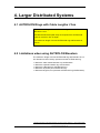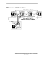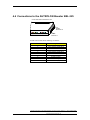
1
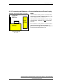
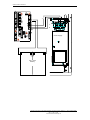
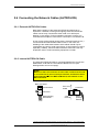
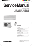
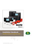
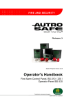
Interactive Fire Alarm System Release 3 Installation Handbook Fire Alarm Control Panel, BS-310/320 Controller, BC-320 Protecting life, environment and property... 116-P-ASAFE-FA/DE, Rev. J, 2011-12-06 COPYRIGHT © This publication, or parts thereof, may not be reproduced in any form, by any method, for any purpose. Autronica Fire and Security AS and its subsidaries assume no reponsibility for any errors that may appear in the publication, or for damages arising from the information in it. No information in this publication should be regarded as a warranty made by Autronica Fire and Security. The information in this publication may be updated without notice. Product names mentioned in this publication may be trademarks. They are used only for identification. Installation Handbook, AutroSafe Interactive Fire Alarm System, Release 3, 116-P-ASAFE-FA/DE, Rev. J, 2011-12-06, Autronica Fire and Security AS Table of Contents 1. Introduction .......................................................................6 1.1 1.2 1.3 1.4 1.5 1.6 About the Handbook.......................................................................... 6 The Reader ....................................................................................... 6 Reference Documentation................................................................. 7 Environmental Requirements ............................................................ 8 Equipment List ................................................................................... 8 Assembly Drawing............................................................................. 9 Mounting .................................................................................10 1.7 1.8 1.9 1.10 1.11 Introduction ........................................................................................ 10 Location ............................................................................................. 10 Mounting Height / Space Requirement ............................................. 10 Cabinet Dimensions .......................................................................... 11 Surface Mounting .............................................................................. 12 1.11.1 Removing the Front Panel ...................................................... 12 1.11.2 Mounting the Cabinet .............................................................. 14 1.11.3 Cable Inlets / Outlets ............................................................... 15 1.11.4 Cable Connections .................................................................. 15 1.11.5 Mounting the Batteries ............................................................ 16 1.11.6 Reassembling the Front Panel................................................ 16 1.12 Flush Mounting in a Wall ................................................................... 18 1.12.1 Removing the Front Panel ...................................................... 18 1.12.2 Removing the Mounting Plate ................................................. 18 1.12.3 Flush Mounting Before Construction of the Wall .................... 19 1.12.4 Cut Out Dimensions ................................................................ 20 1.12.5 Mounting the Cabinet .............................................................. 20 1.12.6 Reassembling the Mounting Plate .......................................... 20 1.12.7 Cable Inlets / Outlets ............................................................... 21 1.12.8 Cable Connections .................................................................. 21 1.12.9 Mounting the Batteries ............................................................ 21 1.12.10 Reassembling the Front Panel ............................................. 21 1.12.11 Mounting Several Panels in a 19'' Rack ............................... 21 2. Internal Cable Connections .............................................22 2.1 2.2 2.3 2.4 2.5 2.6 Introduction ........................................................................................ 22 Before Connecting Cables ................................................................ 22 Location of Fuses .............................................................................. 23 2.3.1 Fuses on Power Supply, BSS-103A/02 .................................. 23 2.3.2 Fuses on Connection Module, BSF-310B .............................. 24 Shielding and Earthing ...................................................................... 25 2.4.1 Introduction ............................................................................. 25 2.4.2 Definitions ............................................................................... 25 Power Supply and Battery Connections............................................ 25 2.5.1 Connecting 230 VAC to Power Supply BSS-103A/02 ............ 25 2.5.2 Connecting the Batteries to Connection Module and Power Supply .......................................................................... 27 Connecting the Network Cables (AUTROLON) ................................ 29 Installation Handbook, AutroSafe Interactive Fire Alarm System, Release 3, 116-P-ASAFE-FA/DE, Rev. J, 2011-12-06, Autronica Fire and Security AS 2.7 2.8 2.6.1 External AUTROLON Cables.................................................. 29 2.6.2 Internal AUTROLON Cable..................................................... 29 Internal Cable Connections - Overview............................................. 30 Connections for Temperature Compensated Battery Charging Voltage .............................................................................................. 32 2.8.1 Introduction ............................................................................. 32 2.8.2 Connecting the Cable to External Temperature Sensor ......... 33 3. Installing I/O Modules .......................................................34 3.1 3.2 3.3 Introduction ........................................................................................ 34 Front View of I/O Module................................................................... 35 Mounting / Removing I/O Modules .................................................... 36 3.3.1 General ................................................................................... 36 3.3.2 Mounting ................................................................................. 36 3.3.3 Removing ................................................................................ 37 3.3.4 Before Connecting Cables ...................................................... 37 3.4 Data Sheets - I/O Modules ................................................................ 37 3.5 Power Module, BSS-310 ................................................................... 38 3.6 Communication Module, BSL-310 .................................................... 39 3.7 Loop Driver Module, BSD-310 / BSD-311......................................... 40 3.8 Output Module, Monitored, BSB-310 ................................................ 41 3.9 Output Module, BSJ-310 ................................................................... 42 3.10 Input Module, Monitored, BSE-310 ................................................... 43 3.11 Input Module, BSE-320 ..................................................................... 44 Larger Distributed Systems .............................................45 4.1 4.2 4.3 4.4 AUTROLON Rings with Cable Lengths >1km .................................. 45 Limitations when using AUTROLON Boosters.................................. 45 Overview - Cable Connections .......................................................... 46 Connections to the AUTROLON Booster BSL-325 ........................... 47 5. Interfacing AutroMaster_5000 .........................................48 5.1 5.2 5.3 General .............................................................................................. 48 Connections - Overview .................................................................... 49 Application with several AUTROLON rings ....................................... 50 5.3.1 General ................................................................................... 50 5.3.2 Application with Twisted Pair Cabling ..................................... 52 5.3.3 Application with Fibre Optic Cabling ....................................... 53 6. Guidelines for the Installation and Addressing of Loop Units ...............................................................................54 6.1 6.2 6.3 6.4 6.5 Introduction ........................................................................................ 54 Parameters Used During Configuration ............................................ 54 Which Parameters are Known? ........................................................ 55 Guidelines - Known Cable Layout ..................................................... 55 Guidelines - Unknown Cable Layout ................................................. 56 7. Service and Maintenance .................................................57 7.1 7.2 7.3 Introduction ........................................................................................ 57 Monthly Maintenance ........................................................................ 57 Annual Service and Maintenance ..................................................... 57 Installation Handbook, AutroSafe Interactive Fire Alarm System, Release 3, 116-P-ASAFE-FA/DE, Rev. J, 2011-12-06, Autronica Fire and Security AS 8. Reader’s Comments .........................................................61 Installation Handbook, AutroSafe Interactive Fire Alarm System, Release 3, 116-P-ASAFE-FA/DE, Rev. J, 2011-12-06, Autronica Fire and Security AS Introduction 1. Introduction 1.1 About the Handbook This handbook is intended to provide all necessary information for the installation of the AutroSafe Fire Alarm Control Panel (BS-310/320) and the Controller BC-320. It also gives detailed information on connections to the network (AUTROLON) and guidelines for the installation and addressing of loop units. Information on the connection of detectors and other loop units to the detection loop is found in a separate handbook, Connecting Loop Units, 116-P-CONNECTLOOPUNIT/GBD (pdf filname connectloopunit_gbd). The Fire Alarm Control Panel and the Controller are identical as far as installation procedures are concerned. Note that all illustrations throughout this handbook shows the Fire Alarm Control Panel with buttons, indicators and display. The Controller has a front blackplate, and the Display Board BSR-310, Operator Board BZ-310 and Processor Board EAC-300 are not integrated parts of the system unit. Note that this handbook deals with the mechanical and electrical installation only. All tasks described in the handbook are to be performed without applying power to the system. Power must not be applied before commissioning, refer to Commissioning Handbook. ! POWER OFF! The chapter «Service and Maintenance» outlines the recommended monthly and annual service and maintenance procedures. 1.2 The Reader The handbook is intended to be used by Autronica Fire and Security trained service and technical personnel who are responsible for the installation of the AutroSafe Interactive Fire Alarm System. Installation Handbook, AutroSafe Interactive Fire Alarm System, Release 3, 116-P-ASAFE-FA/DE, Rev. J, 2011-12-06, Autronica Fire and Security AS Introduction 1.3 Reference Documentation In addition to this handbook, Autronica Fire and Security offers the following documentation: Handbook System Specification Installation Handbook, Fire Alarm Control Panel (BS-310/320) / Controller (BC-320) Installation Handbook, Operator Panel (BS-330) Installation Handbook, Repeater Panel (BU-320) / Information Panel (BV-320) Installation Handbook, Battery Cabinet (SY-310) Connecting Loop Units Commissioning Handbook Operator’s Handbook, Fire Alarm Control Panel (BS-310/320) / Operator Panel (BS330) Operator's Handbook, Repeater Panel (BU-320) Operator's Handbook, Information Panel (BV-320) Shortform User Guide Shortform Configuration Guide (for the AutroSafe Demo Board) Wall Chart Wall Chart Menu Structure User Guide, Loop Diagnostic Tool, AS-2000 User Guide, Loop Simulator Tool User Guide, Loop Calculator Tool User Guide, Merge Tool User Guide, Power Calculator Sheet Item Number P-ASAFE/XE P-ASAFE-FA/DE P-ASAFE-OP/DE P-ASAFE-RI/DE P-ASAFE-BC/DE P-CONNECTLOOPUNIT/DGB P-ASAFE/EE P-ASAFE-FO/FE P-ASAFE-FB/FE P-ASAFE-IN/FE P-ASAFE-SH/LE P-ASAFE-SH/VE P-ASAFE-WE/LX P-ASAFE-CH/LX P-ASAFE/MX P-ASAFE-AS/FE P-ASAFE-LS/FE P-ASAFE-LC/FE P-ASAFE-MT/FE P-ASAFE-PC/FE Installation Handbook, AutroSafe Interactive Fire Alarm System, Release 3, 116-P-ASAFE-FA/DE, Rev. J, 2011-12-06, Autronica Fire and Security AS Introduction 1.4 Environmental Requirements The equipment complies to environmental conditions of IEC-721-3-3 class 3k5. Ambient temperature:-5 to +40 C Degree of protection:IEC-529/IP30 1.5 Equipment List The AutroSafe Fire Alarm Control Panel consists of the following: BS-310/01: Operator front panel *, complete with: BSR-310:Display Board with LCD BSZ-310Operator Board EAC-300Processor Board Option: BUP-310Printer EAU-310LON Interface (BS-320 type) EAU-321Serial Port Communication Board EAU-330Ethernet Communication Board BC-310/01:Controller rear cabinet UEA-323:Cabinet (H=321 mm, W=315 mm, D=139 mm) BSL-310:Communication Module BSF-310:Connection Module BSS-310:Power Module BSS-103A/02: Power Supply Options: Batteries2 x 12V / 12Ah (maximum) Modules: BSD-310Loop Driver Module (127 addresses) BSD-311High-power Loop Driver Module BSB-310Output Module (4 relays, monitored) BSJ-310Output Module (8 open collector outputs) BSE-310Input Module (4 inputs, monitored) BSE-320Input Module (8 inputs, galvanic isolated) * The Controller serves as a connection unit for Loop Driver Modules, I/O modules and power supply only. The cabinet is thus delivered with a black panel in front instead of the Operator Front Panel. Installation Handbook, AutroSafe Interactive Fire Alarm System, Release 3, 116-P-ASAFE-FA/DE, Rev. J, 2011-12-06, Autronica Fire and Security AS Introduction 1.6 Assembly Drawing Front Panel LON Interface EAU-310 Cabinet Connection Module BSF-310B Display Board BSR-310 Loop Driver or I/O Modules (on top of Power and Comm. Module) Processor Board EAC-300 Communication Module BSL-310 Operator Board BSZ-310 Power Module BSS-310A/02 Power Supply BSS-103/01 Battery Cover Printer BUP-310 Battery Shelf (Not included in Controller, BC-320) Installation Handbook, AutroSafe Interactive Fire Alarm System, Release 3, 116-P-ASAFE-FA/DE, Rev. J, 2011-12-06, Autronica Fire and Security AS Mounting Mounting 1.7 Introduction This chapter deals with the following mounting alternatives: Surface mounting Flush mounting in a wall For surface mounting and flush mounting in a wall, a stand-alone cabinet is used. 1.8 Location The Fire Alarm aControl Panel must be located in, or near by, the entrance. Both the Fire Alarm Control Panel and the Controller must be placed according to local regulations and in consultation with the fire brigade. 1.9 Mounting Height / Space Requirement To ensure optimal readability of the Fire Alarm Control Panel's display, the recommended mounting height of this cabinet top is approximately 175 cm above the floor. For surface mounting and flush mounting in a wall, there must be a free space of minimum 50 mm from the cabinet top to the ceiling in order to fasten the top screw on the front panel door after the installation. A crosshead screwdriver can be used for this purpose. Installation Handbook, AutroSafe Interactive Fire Alarm System, Release 3, 116-P-ASAFE-FA/DE, Rev. J, 2011-12-06, Autronica Fire and Security AS Mounting 1.10 Cabinet Dimensions The cabinet (Fire Alarm Control Panel / Controller) has the following dimensions: (cabinet) (front) (cabinet) (front) (Ref. BS-1109) Installation Handbook, AutroSafe Interactive Fire Alarm System, Release 3, 116-P-ASAFE-FA/DE, Rev. J, 2011-12-06, Autronica Fire and Security AS Mounting 1.11 Surface Mounting 1.11.1 Removing the Front Panel All the internal units within the rear cabinet are fastened to a mounting plate. The cabinet is delivered with the front panel fastened to the cabinet. Unscrew the 2 screws on the top and the bottom on the right hand side of the front panel. Lock screw Lock screw Open the front panel. Installation Handbook, AutroSafe Interactive Fire Alarm System, Release 3, 116-P-ASAFE-FA/DE, Rev. J, 2011-12-06, Autronica Fire and Security AS Mounting Disconnect the ribbon cable(s) between the front panel and the cabinet by removing the connector on the BSF-310B board. Ribbon cable connection Unscrew the 4 wing nuts on the right and left hand side of the cabinet, then close the front panel, and remove the front panel from the cabinet . Front Panel wing nuts Installation Handbook, AutroSafe Interactive Fire Alarm System, Release 3, 116-P-ASAFE-FA/DE, Rev. J, 2011-12-06, Autronica Fire and Security AS Mounting 1.11.2 Mounting the Cabinet The cabinet has 5 moun7ting holes located at the rear. The upper holes are of key-hole-type. Consult the illustration above, and do the following: Mark and drill all the holes according to the illustation. Partly fasten the upper screws. Hang the cabinet onto the upper screws. Partly fasten the bottom screws. Tighten all screws. Installation Handbook, AutroSafe Interactive Fire Alarm System, Release 3, 116-P-ASAFE-FA/DE, Rev. J, 2011-12-06, Autronica Fire and Security AS Mounting 1.11.3 Cable Inlets / Outlets Note that two gland plates are fitted to the cabinet, one with predrilled holes and one blank. When feeding the cables, use whichever is appropriate. Entry should always be from top as bottom entry is restricted, particularly if batteries are fitted. The illustration above shows the positioning and dimensions of the cable inlets. Feed all the cables into the cabinet from the top through the suitable cable inlets. Make sure that the cables are fastened properly. 1.11.4 Cable Connections For detailed information on cable connections, refer to chapter 3 in this handbook. Installation Handbook, AutroSafe Interactive Fire Alarm System, Release 3, 116-P-ASAFE-FA/DE, Rev. J, 2011-12-06, Autronica Fire and Security AS Mounting 1.11.5 Mounting the Batteries Unscrew the screw as shown on the illustration below. Lift the lower part of the cover off the bottom slot and remove the battery cover. Screw Battery Cover Place the batteries in their position as shown, then reassemble the battery cover. 1.11.6 Reassembling the Front Panel When all the necessary cable connections are done, reassemble the front panel. Open the front panel. Tighten the 4 wing nuts on the right and left side inside the cabinet. Interconnect the ribbon cable(s) between the front panel and the cabinet. Close the front panel, and tighten the two lock screws on the top Batteries; and the bottom on the right hand side. 2x12V / 12Ah Installation Handbook, AutroSafe Interactive Fire Alarm System, Release 3, 116-P-ASAFE-FA/DE, Rev. J, 2011-12-06, Autronica Fire and Security AS Mounting Wing nuts Ribbon cable connection Lock screw (front door) Lock screw Installation Handbook, AutroSafe Interactive Fire Alarm System, Release 3, 116-P-ASAFE-FA/DE, Rev. J, 2011-12-06, Autronica Fire and Security AS Mounting 1.12 Flush Mounting in a Wall 1.12.1 Removing the Front Panel All the inside units in the cabinet are fastened to a mounting plate. The cabinet is delivered with the front panels fastened to the cabinet. Follow the procedure described in chapter 2.5.1; unscrew the 2 screws on the top and the bottom on the right hand side of the front panel and open it. disconnect the ribbon cables between the front panel and the cabinet by removing the connector on the BSF-310B board. unscrew the 4 wing nuts on the right and left side inside the cabinet and remove the front panel from the cabinet. 1.12.2 Removing the Mounting Plate To avoid damaging the electronics, the mounting plate inside the cabinet should be removed. Unscrew the 5 screws on the mounting plate inside the cabinet and carefully lift it out of the cabinet. Mounting screws Installation Handbook, AutroSafe Interactive Fire Alarm System, Release 3, 116-P-ASAFE-FA/DE, Rev. J, 2011-12-06, Autronica Fire and Security AS Mounting 1.12.3 Flush Mounting Before Construction of the Wall If a flush mounting is planned before construction of the wall, the cabinet - without the inside units and front panel - can be used as a casting frame. WARNING: To avoid deformation, make sure that the cabinet is supported inside before concreting. Installation Handbook, AutroSafe Interactive Fire Alarm System, Release 3, 116-P-ASAFE-FA/DE, Rev. J, 2011-12-06, Autronica Fire and Security AS Mounting 1.12.4 Cut Out Dimensions The illustration below shows the cabinet’s cut out dimensions. The dimensions given include space for the cover frame, but not for the required free space of minimum 50 mm on the top / bottom of the cabinet. 1.12.5 Mounting the Cabinet The cabinet has 4 mounting holes located on the left and right flange. Consult the illustration above, and do the following: Mark and drill all the holes according to the illustration. Place the cabinet into the wall and fasten the 4 screws. 1.12.6 Reassembling the Mounting Plate Reassemble the mounting plate carefully into its position inside the cabinet. Tighten the screws. Installation Handbook, AutroSafe Interactive Fire Alarm System, Release 3, 116-P-ASAFE-FA/DE, Rev. J, 2011-12-06, Autronica Fire and Security AS Mounting 1.12.7 Cable Inlets / Outlets Feed all the cables into the cabinet from the rear through the suitable cable inlets (refer to chapter 2.5.3). 1.12.8 Cable Connections For detailed information on cable connections, refer to chapter 3 in this manual. 1.12.9 Mounting the Batteries Follow the instructions in chapter 2.5.5. 1.12.10 Reassembling the Front Panel Follow the instructions in chapter 2.5.6. 1.12.11 Mounting Several Panels in a 19'' Rack Rack mounting requires a free space of minimum 50 mm on the top / bottom of the cabinet to be able to open and close the front panel. For this purpose, a 19'' mounting plate can be used (UW-1459). Installation Handbook, AutroSafe Interactive Fire Alarm System, Release 3, 116-P-ASAFE-FA/DE, Rev. J, 2011-12-06, Autronica Fire and Security AS Internal Cable Connections 2. Internal Cable Connections 2.1 Introduction The Fire Alarm Control Panel / Controller is customized according to each specific delivery. Most of the internal cabling is already done (see Cable Connections - Overview), as the control panel will always be delivered from the factory with the mandatory internal I/O modules; Power Module BSS-310 and the Communication Module BSL-310 installed. In addition to a description of the location of the fuses and internal cable connections overview, this chapter covers the following: Connecting the Power Supply & Battery Charger Connecting the Battery Connecting the network cables (AUTROLON) Connections for Temperature Compensated Battery Charging Voltage (when external battery connection is used) 2.2 Before Connecting Cables Before connecting cables, make sure that the mains power is not connected. ! Remove the fuses F1 and F2 on the Power Supply (refer to illustration in the subsequent chapter). Do not replace the fuses until commissioning of the system. POWER OFF! Installation Handbook, AutroSafe Interactive Fire Alarm System, Release 3, 116-P-ASAFE-FA/DE, Rev. J, 2011-12-06, Autronica Fire and Security AS Internal Cable Connections 2.3 Location of Fuses 2.3.1 Fuses on Power Supply, BSS-103A/02 Remove the fuses F1 and F2 on the Power Supply. Do not replace the fuses until commissioning of the system. ! POWER OFF! Fuse No. Size Type Slow/Fast Protecting F1 F2 F3 2A 6,3 A 1A T2AH/250V AC F6,3AH/250V AC T1AL/250V AC Slow (T) Fast (F) Slow (T) Mains Battery External 24V DC F3 F2 F1 Remove fuses F1 and F2. Do not replace the fuses until commissioning of the system. Installation Handbook, AutroSafe Interactive Fire Alarm System, Release 3, 116-P-ASAFE-FA/DE, Rev. J, 2011-12-06, Autronica Fire and Security AS Internal Cable Connections 2.3.2 Fuses on Connection Module, BSF-310B Fuse No. Size Type Slow/Fast F1 F2 F3 F4 3,15 A 4,0 A 2A 2,5 A T3,15AL/250V AC T4AL/250V AC F2AL/250V AC T2,5AL/250V AC Slow (T) Slow (T) Fast (F) Slow (T) Protecting Charger Circuit Battery I/O Power Battery / External 24V F1 F2 F4 F3 Installation Handbook, AutroSafe Interactive Fire Alarm System, Release 3, 116-P-ASAFE-FA/DE, Rev. J, 2011-12-06, Autronica Fire and Security AS Internal Cable Connections 2.4 Shielding and Earthing 2.4.1 Introduction Due to requirements in EN54 and generic EMC-requirements, it is very important to keep in mind how to make earthing and shielding of cables when installing. 2.4.2 Definitions Protective Earth Termination point to the external protective earth. In AutroSafe this is the connection at the BSS-103A/02 block terminal (terminal 1). Protective Earth to Cabinet Main earth connection which ensures that the cabinet always is connected to earth. Note: Must not be removed or unscrewed. Chassis Electrical connection to the steel cabinet. A screw on the rear mounting plate (up left to the Power Supply) is provided for this. This is in turn connected to the Protective Earth for human protection and earthing. Shield Termination point for the shielding of cables, where provided. 0V_BAT Reference point for the battery circuit (isolated from earth/chassis). Detail drawing of Power Supply / upper part of Fire Alarm Control Panel / Controller Protective Earth 2.5 Power Supply and Battery Connections 2.5.1 Connecting 230 VAC to Power Supply BSS-103A/02 NOTE! The illustration below shows an overviewChassis of the mains connection (230 VAC) to the Power Protective Earth to Supply BSS-103A/02. The connection of mains power is done during commissioning. Until then, Cabinet do not connect the mains power . Schematic outline inside cabinet - Front view Protective Earth (terminal) 230 V AC Power Supply BSS103A/02 Live Neutral Installation Handbook, AutroSafe Interactive Fire Alarm System, Release 3, 116-P-ASAFE-FA/DE, Rev. J, 2011-12-06, Autronica Fire and Security AS Internal Cable Connections Protective Earth ! In the fixed mains wiring to the panel a two-pole disconnect device must be provided to disconnect the equipment from the power supply when servicing is required. Normally, this switch is a two-pole automatic fuse located in the fuse terminal box at the premises. This fuse location must be marked "Fire Alarm System". Power Supply The isolation of the mains wiring must be of either: inflammability class V2 or the wiring has to be fixed to the cabinet separated from all other cables. Installation Handbook, AutroSafe Interactive Fire Alarm System, Release 3, 116-P-ASAFE-FA/DE, Rev. J, 2011-12-06, Autronica Fire and Security AS Internal Cable Connections 2.5.2 Connecting the Batteries to Connection Module and Power Supply Schematic outline inside cabinet - Front view Connection Module BSF-310B Power Supply BSS103A/02 Batteries 24V/12Ah NOTE! The illustration below gives an overview of the connections from the Connection Module to the Power Supply and to the batteries. The connection of the batteries is done during commissioning. Until then, do not connect the batteries. If the cabinet is to be placed in an environment with high humidity, an appropriate type of grease should be applied on the battery poles to avoid possible development of verdigris. Connection Module BSF-310B Installation Handbook, AutroSafe Interactive Fire Alarm System, Release 3, 116-P-ASAFE-FA/DE, Rev. J, 2011-12-06, Autronica Fire and Security AS Internal Cable Connections + + - - + - Power Supply - - + - + + 24V / 12Ah Battery Installation Handbook, AutroSafe Interactive Fire Alarm System, Release 3, 116-P-ASAFE-FA/DE, Rev. J, 2011-12-06, Autronica Fire and Security AS Internal Cable Connections 2.6 Connecting the Network Cables (AUTROLON) 2.6.1 External AUTROLON Cables Note that the polarity of the external AUTROLON cables has no importance. Likewise, incoming and outgoing external AUTROLON cables can be freely connected to either LON-A or LON-B (see drawing on next page). For documentation purposes, however, we recommend that output is connected to A and input is connected to B. In high-current environments (power plants, electrical machinery etc.) it is recommended that shielded cable is used. In this case, the shielding of the cable stubs between each cabinet should only be connected at one end to avoid ground loops. If high-frequency noise is expected (>10MHz), then both ends should be connected. This may be present close to radio transmitting equipment or similar. 2.6.2 Internal AUTROLON Cable The internal AUTROLON cable is connected between the Connection Module BSF-310B and the LON Interface Board EAU-310 (see drawings below and on next page). NOTE: Make sure that the connector on each side is mated correct and is connected to all pins on the 4-pin terminal, and that the wires point downwards on the BSF-310B board, and inwards on the EAU-310 board. BSF-310 board 4-pin terminal EAU-310 board Connector Connector Wires pointing downwards 4-pin terminal Wires pointing inwards Installation Handbook, AutroSafe Interactive Fire Alarm System, Release 3, 116-P-ASAFE-FA/DE, Rev. J, 2011-12-06, Autronica Fire and Security AS Internal Cable Connections 2.7 Internal Cable Connections - Overview Watchdog output External AUTROLON cables Connection Module BSF-310B Internal AUTROLON cable to LON Interface board EAU-310 Watchdog output (X4-2 / X4-3): Normal open. Watchdog failure: To Communication break To Front Panel Operator Board BSZ-310 Module BSL-310 Shield LON A LON A Shield LON B LON B External 24V + Input connection 1 External 24V + Input connection 2 - X7-3 X7-2 X7-1 X6-3 X6-2 X6-1 X5-4 X5-3 X5-2 X5-1 LON LON LON LON +24V 0V +24V 0V X4-1 X4-2 X4-3 X3-1 X3-2 X2-1 X2-2 X1-1 X1-2 X1-3 Shield +12V Signal 0V Battery +24V Battery 0V I/O Power +24V I/O Power 0 V Charger +24V Charger 0V To Chassis connection (connection above BSS-103A/02) LON A LON A Installation LON A Handbook, AutroSafe Interactive Fire Alarm System, Release 3, 116-P-ASAFE-FA/DE, Rev. J, 2011-12-06, LON B Autronica Fire and Security AS LON B LON B External 24V + Internal Cable Connections NOTE: 10 9 8 7 6 5 4 3 2 1 Connector 8 + 7 T 6 5 + 4 230V 3 2 1 Protective Earth Neutral 230V +24V DC to battery 0V Test External 24V Output 10 9 8 7 6 5 4 3 2 1 Screw Terminals on Power Supply BSS-103A/02 The following internal cable connections are already done when the product leaves the factory: Power Module BSS-310: A small ribbon cable is used between the Power Module and the Power Supply BSS-103A/02. Communication Module BSL-310: Two small ribbon cables are used. One cable is used to interconnect the Communication Module and the Connection Module BSF-310B. The other cable is used to interconnect the Communication Module and the Power Supply BSS-103A/02. Installation Handbook, AutroSafe Interactive Fire Alarm System, Release 3, 116-P-ASAFE-FA/DE, Rev. J, 2011-12-06, Autronica Fire and Security AS Internal Cable Connections 2.8 Connections for Temperature Compensated Battery Charging Voltage 2.8.1 Introduction The Power Supply BSS-103A/02 in the Fire Alarm Control Panel BS310/320 / Controller BC-320 is provided with a temperature sensor for temperature compensated battery charging voltage. The internal connections to the sensor is already done when the product leaves the factory. The cable with the sensor has to be taped to the battery cover bracket. If a solution with external battery connection is used, the temperature sensor must be removed and a longer cable from an external battery cabinet must be attached to this connection (refer to next chapter). AutroSafe cabinet Fix the temperature sensor to the battery cover bracket with electrical tape. Installation Handbook, AutroSafe Interactive Fire Alarm System, Release 3, 116-P-ASAFE-FA/DE, Rev. J, 2011-12-06, Autronica Fire and Security AS Internal Cable Connections 2.8.2 Connecting the Cable to External Temperature Sensor When a solution with external battery connection is used, the sensor must be removed from the Power Supply BSS-103A/02. A 3m cable must then be connected between the Power Supply BSS-103A/02 in the Fire Alarm Control Panel / Controller and the external temperature sensor mounted on a connector in the Battery Cabinet SY-310. The cable for this purpose is delivered with the battery cabinet. For information on cable connections, consult the illustrations below. Remove the front cover on the Power Supply BSS-103A/02 (in the Fire Alarm Control Panel / Controller). Remove the temperature sensor. Power Supply BSS-103A/02 in Fire Alarm Control Panel or Controller Temperature Sensor Power Supply BSS-103A/02 in Fire Alarm Control Panel or Controller Connect the cable from the Battery Cabinet to the connector on the Power Supply BSS-103A/02. Battery Cabinet Reassemble the front cover on the Power Supply BS-103/01. Fasten cable with strips Installation Handbook, AutroSafe Interactive Fire Alarm System, Release 3, 116-P-ASAFE-FA/DE, Rev. J, 2011-12-06, Autronica Fire and Security AS Installing I/O Modules 3. Installing I/O Modules 3.1 Introduction This chapter provides information on the mounting and removal of I/O modules. Note that the internal Power Module (BSS-310) and the Communication Module (BSL-310) are already mounted in a fixed position when the product leaves the factory (refer to 1.5). Installation Handbook, AutroSafe Interactive Fire Alarm System, Release 3, 116-P-ASAFE-FA/DE, Rev. J, 2011-12-06, Autronica Fire and Security AS Installing I/O Modules 3.2 Front View of I/O Module Installation Handbook, AutroSafe Interactive Fire Alarm System, Release 3, 116-P-ASAFE-FA/DE, Rev. J, 2011-12-06, Autronica Fire and Security AS Installing I/O Modules 3.3 Mounting / Removing I/O Modules 3.3.1 General Note! Make sure the mains power is OFF! Note: The Power Module (BSS-310) must always be mounted first on the rail - at the bottom - before any other modules. The Communication Module (BSL-310) is then mounted on top of the Power Module. All other modules can be mounted in arbitrary order on top of these two modules. BSL-310 BSS-310 Fixed Position When the system is to be configured at a later point, note that the AutroSafe Configuration Tool graphically shows the first module on the top of the figure and the following in descending order. This is opposite to the physical mounting, and must be taken into consideration when configuring the system. Also note that the configuration tool does not show the BSS-310 and BSL-310. 3.3.2 Mounting The connection block on the I/O module must be pointing to the right when the module is to be inserted. Snap the right side of the fastener onto the mounting rail (1), then press the module slightly inwards (2) until the left side fastens. 2 1 Then, carefully press the module downwards as far as possible. Make sure that the module is properly connected to the module below. Installation Handbook, AutroSafe Interactive Fire Alarm System, Release 3, 116-P-ASAFE-FA/DE, Rev. J, 2011-12-06, Autronica Fire and Security AS Installing I/O Modules 3.3.3 Removing Unplug the connection block. Use a screwdriver to carefully lift the topmost module upwards (1) until the connector between the modules is free. Use the screwdriver to slightly bend the left side of the fastener towards left (2) until it loosens, then remove (3) the module. If necessary, continue removing the next one in the same way. 1 2 3 3.3.4 Before Connecting Cables Before connecting cables, make sure that the mains power is not connected. ! Remove the fuses F1 and F2 on the Power Supply (refer to illustration in chapter 3.3.1). Do not replace the fuses until commissioning of the system. POWER OFF! 3.4 Data Sheets - I/O Modules The AutroSafe User Documentation provides data sheets for I/O modules, including a short description of the I/O module, its application, plus technical specifications and cabling. The subsequent chapters in this handbook provide necessary information on connections, screw terminals and signals. Power Module, BSS-310 Communication Module, BSL-310 Loop Driver Module, BSD-310 / BSD-311 Output Module, monitored, BSB-310 Output Module, BSJ-310 Input Module, monitored, BSE-310 Input Module, BSE-320 Installation Handbook, AutroSafe Interactive Fire Alarm System, Release 3, 116-P-ASAFE-FA/DE, Rev. J, 2011-12-06, Autronica Fire and Security AS Installing I/O Modules 3.5 Power Module, BSS-310 The I/O module has the following connections: Screw Terminal no. 1 2 3 4 5 6 7 8 9 10 Signal +24 V Input +24 V Input 0 V Input 0 V Input Chassis Chassis Not in use Not in use Not in use Not in use The module has two green indicators; Right green indicator (H1) - the presence of 24V DC Left green indicator (H2) - the presence of 5V DC Front view when mounted on rail Plug-in Connection Block Screw terminal 10 Screw terminal 1 Green indicator H2 (5V) Green indicator H1 (24V) Schematics BSF-310B + 5 1 2 + - 4 BSS-310 I/O M odules 3 4 - 5 6 Chassis 24V DC input 0V Chassis Internal 1 3 5 BSS-310 Internal Internal + 24V reg + 5V reg 0V Installation Handbook, AutroSafe Interactive Fire Alarm System, Release 3, 116-P-ASAFE-FA/DE, Rev. J, 2011-12-06, Autronica Fire and Security AS Installing I/O Modules 3.6 Communication Module, BSL-310 Connector on ribbon Cable 1 To Connection Module BSF-310B 1 2 3 4 5 6 7 8 9 10 Connector on ribbon Cable 2 To Power Module BSS-103A/02 1 2 3 4 5 6 Signal INT RS_GND TX RS_GND N.C. (GND) RS_GND RX RS_GND CTS RS_GND Signal TEST N.C. N.C. GND MAINS_OK N.C. APPLY_LOAD Schematics Cable 1 BSF-310B Connection Module BSL-310 BSS-103A/02 Power Supply Cable 2 Installation Handbook, AutroSafe Interactive Fire Alarm System, Release 3, 116-P-ASAFE-FA/DE, Rev. J, 2011-12-06, Autronica Fire and Security AS Installing I/O Modules 3.7 Loop Driver Module, BSD-310 / BSD-311 Screw Terminal no. 1 2 3 4 5 6 7 8 9 10 Signal OUT + (+24V) OUT - (0V) Shield IN + IN Shield F/S + F/S Chassis Chassis Green indicator, H5. Communication indicator that gives a pulsing green light during traffic. Red indicator, H1. Fail_Safe indicator that gives a steady red light if a communication failure occurs, i.e. the system does not respond to an alarm. Front view when mounted on rail Screw terminal 10 Screw terminal 1 Red indicator H1 Green indicator H5 Schematics BSD-310 + Detector 1 3 24V DC Out - 2 3 1 2 3 In - 2 1 + 4 3 2 1 5 6 From previous Loop Driver Module + Loop Driver Module - 7 F/S Signal 8 To next Loop Driver Module Installation Handbook, AutroSafe Interactive Fire Alarm System, Release 3, 116-P-ASAFE-FA/DE, Rev. J, 2011-12-06, Autronica Fire and Security AS Installing I/O Modules 3.8 Output Module, Monitored, BSB-310 Screw Terminal no. 1 2 3 4 5 6 7 8 9 10 Signal Output AK1 - (0V) Output AK1 + (+24V) Output AK2 - (0V) Output AK2 + (+24V) Output AK3 - (0V) Output AK3 + (+24V) Output AK4 - (0V) Output AK4 + (+24V) Input 24 VBAT Input 0 VBAT Front view when mounted on rail Screw terminal 10 Screw terminal 1 Schematics - Monitored Output Terminal point 2, 4, 6, 8 + 24V_BAT Sense Terminal point 1, 3, 5, 7 Schematics - Fault Warning Routing Equipment (FWRE) Output Output 4 only. Ext FW Routing Eq 8 (Not connected) 24V_BAT Sense FWRE 7 0V_BAT Installation Handbook, AutroSafe Interactive Fire Alarm System, Release 3, 116-P-ASAFE-FA/DE, Rev. J, 2011-12-06, Autronica Fire and Security AS Installing I/O Modules 3.9 Output Module, BSJ-310 Screw Terminal no. 1 2 3 4 5 6 7 8 9 10 Signal OC1 OC2 OC3 OC4 OC5 OC6 OC7 OC8 24 VBAT Output Chassis Front view when mounted on rail Screw terminal 10 Screw terminal 1 Terminal 9 + Output +24V External terminal list Output 1 Output 8 Maximum 100 mA Schematics + 24V Output 9 Output 1-8 0V_BAT Installation Handbook, AutroSafe Interactive Fire Alarm System, Release 3, 116-P-ASAFE-FA/DE, Rev. J, 2011-12-06, Autronica Fire and Security AS Installing I/O Modules 3.10 Input Module, Monitored, BSE-310 Screw Terminal no. 1 2 3 4 5 6 7 8 9 10 Signal IN1 + IN1 - (0V) IN2 + IN2 - (0V) IN3 + IN3 - (0V) IN4 + IN4 - (0V) 24 VBAT 0 VBAT Front view when mounted on rail Screw terminal 10 Screw terminal 1 Signal resistor 1 2K Input 2 250-2000 Ohm (Recommended value is 470 Ohm) Monitoring resistor Schematics V+ R Signal Terminal point 1, 3, 5, 7 Sense 0V 0V Terminal point 2, 4, 6, 8 Installation Handbook, AutroSafe Interactive Fire Alarm System, Release 3, 116-P-ASAFE-FA/DE, Rev. J, 2011-12-06, Autronica Fire and Security AS Installing I/O Modules 3.11 Input Module, BSE-320 Screw Terminal nr. 1 2 3 4 5 6 7 8 9 10 Signal IN1 IN2 IN3 IN4 IN5 IN6 IN7 IN8 n.c. INx-power supply Common source to all inputs (+) Schematics Installation Handbook, AutroSafe Interactive Fire Alarm System, Release 3, 116-P-ASAFE-FA/DE, Rev. J, 2011-12-06, Autronica Fire and Security AS 4. Larger Distributed Systems 4.1 AUTROLON Rings with Cable Lengths >1km The maximum length of the AUTROLON ring without AUTROLON Boosters is 1km. AUTROLON Boosters (BSL-325) are required if the AUTROLON cable is more than 1km in length. The maximum length of a total AUTROLON ring with Boosters is 2,8 km. 4.2 Limitations when using AUTROLON Boosters The maximum length of a total AUTROLON ring with Boosters is 2,8 km. Boosters must be evenly spread round the AUTROLON ring. Maximum 1000 metres between any two Boosters. Maximum 8 panels between any two Boosters. Maximum 6 Boosters per AUTROLON ring. Maximum 32 panels per AUTROLON ring. Maximum length 2,8 km (the total AUTROLON ring with Boosters). Installation Handbook, AutroSafe Interactive Fire Alarm System, Release 3, 116-P-ASAFE-FA/DE, Rev. J, 2011-12-06, Autronica Fire and Security AS 4.3 Overview - Cable Connections Installation Handbook, AutroSafe Interactive Fire Alarm System, Release 3, 116-P-ASAFE-FA/DE, Rev. J, 2011-12-06, Autronica Fire and Security AS 4.4 Connections to the AUTROLON Booster BSL-325 Front view when mounted on rail Screw terminal 10 Indicators H8 H7 H6 H5 H4 H3 H2 H1 Screw terminal 1 The BSL-325 module has the following connections: Screw Terminal no. 1 2 3 4 5 6 7 8 9 10 Signal LON A (polarity independent) LON A (polarity independent) Shield LON A LON B (polarity independent) LON B (polarity independent) Shield LON B Do NOT connect Do NOT connect +24 VDC Supply 0 VDC Supply Installation Handbook, AutroSafe Interactive Fire Alarm System, Release 3, 116-P-ASAFE-FA/DE, Rev. J, 2011-12-06, Autronica Fire and Security AS Interfacing AutroMaster_5000 5. Interfacing AutroMaster_5000 5.1 General The example below shows part of a larger AutroSafe system connected to an AutroMaster 5000 Colour Graphic System on the top level. The Local Operating Network (AUTROLON) is installed as a ring loop. A high-level bus based ethernet, LAN, can be used between the different work stations in the AutroMaster 5000 system. The AUTROLON is connected to the workstations. The operator panels can be installed in different buildings, operation zones, etc. AutroMaster 5000 System LAN LAN Work station Work station Local Operating Network (AUTROLON) Local Operating Network (AUTROLON) ALARM ALARM ALARM Fi re ext.. acktivated Silence buzzer Fi re vent. a ctiv. Fi re Brig. recvd. Power More Alarms Earlywarning System fau lt Fun ction disabled Test INFOR MASJONSPANEL Fire ex t. aktivate d Silence sound ers Silence buzzer Fire vent. a ctiv. 1 2 3 4 5 6 7 8 9 C Power Prewarning Early warning Fault 0 System fau lt Function disabled Test ? Sile nc e buzz er Fire ve nt . acti v. Fire ext.. acktivated Reset Fire Brig. recvd. Prewarn ing Fau lt MoreAlarms Fire B rig. re cv d. Silence sound ers More Alar ms Powe r Reset 1 2 3 4 5 6 8 9 7 C 0 ? Self Verify Self Verify I/O A utro nic a A utronica K NUS GLA SSET T RYKK HER PRESS H ER E B REAK GLASS A utro nic a I/O A utro nic a A utro nic a K NUS GLA SSET T RYKK HER PRESS H ER E B REAK GLASS K NUS GLA SSET T RYKK HER PRESS H ERE B REAK G LASS K NUS GLA SSET T RYKK HER PRESS H ER E B REAK GLASS A utro nica I/O I/O I/O A utro nic a A utro nic a A utro nica Installation Handbook, AutroSafe Interactive Fire Alarm System, Release 3, 116-P-ASAFE-FA/DE, Rev. J, 2011-12-06, Autronica Fire and Security AS Interfacing AutroMaster_5000 5.2 Connections - Overview The interface of the AutroMaster 5000 requires the use of the Ethernet Communication Board, EAU-330. The Ethernet Communication Board, EAU-330 is mounted onto the Processor Board EAC-300 inside the Fire Alarm Control Panel BS-310, or on the top of the LON Interface Board (EAU-310/B) inside the Fire Alarm Control Panel BS320 or Controller BC-320. The connection can be done via a HUB, or directly to an AutroMaster. Connection to a HUB requires a patchcable with internal one-to-one pin connection (straight-through). 19:23 ALARM AUTROSAFE Patchcable with internal one-to-one connection. SelfVerify Fault Fun ctio n Disabled Mute Pan el Function Delayed Fire Brig. Signalled Silence Alarms Mor e Events Reset Power Testing 1 Fire Brig. Disabled 4 Fi re Brig. Fault System F au lt 7 Alarms Disabled Alarms Fault 2 3 5 6 8 9 C 0 i HUB Connection directly to an AutroMaster requires a patchcable with internal crossing of the TX and RX signals (crossover cable). A convenient way to accomplish this is to do the crossing in a junction box. 19:23 ALARM AUTROSAFE Patchcable with internal crossing of the TX and RX signals. SelfVerify Fault Fun ction Disabled Mute Pan el Functio n Delayed Fire Brig. Signalled Power Testi ng Fire Brig. Disabled Fire Brig. Fau lt System F au lt Alarms Disabled Alarms Fault More Events Silence Alarms Reset 1 4 7 2 3 5 6 8 9 C 0 i Installation Handbook, AutroSafe Interactive Fire Alarm System, Release 3, 116-P-ASAFE-FA/DE, Rev. J, 2011-12-06, Autronica Fire and Security AS Interfacing AutroMaster_5000 The Ethernet Communication Board, EAU-330 with a Patchcable connected. Patchcable 5.3 Application with several AUTROLON rings 5.3.1 General AutroMaster 5000 is used as the top level system. AutroMaster 5000 enables a two-way communication with both AUTROLON rings and monitors the entire system. NOTE: The communication is not possible through AUTROLON rings by use of AutroMaster 5000. The connection from the panels on each AUTROLON ring is done via TP or optical fibre and a HUB to AutroMaster 5000. The units BN-300 (Fire Alarm Interface Unit) and BN-310 (Relay Output Unit) are used to identify a limited number of alarms between the AUTROLON rings. For this purpose a detection loop on AUTROLON ring 1 is connected to a detection loop on AUTROLON ring 2. Output (FPE; Fire Protection Equipment) on the BN-310 unit on AUTROLON ring 2 is connected to input (FAI; Fire Alarm Interface) on AUTROLON ring 1 (or opposite). By means of the AutroSafe Configuration Tool, FPE on AUTROLON ring 2 is connected to detection zones (DZ's), which enables alarm transfer to FAI on AUTROLON ring 1. FAI on AUTROLON ring 1 is connected to a Installation Handbook, AutroSafe Interactive Fire Alarm System, Release 3, 116-P-ASAFE-FA/DE, Rev. J, 2011-12-06, Autronica Fire and Security AS Interfacing AutroMaster_5000 detection zone with an appropriate text (for example, Fire, block A2, third floor). The transfer of control functions is done similarly. By means of the configuration tool, the DZ for FAI on AUTROLON ring 1 must be connected to FPE or alarm output for AUTROLON ring 1. Note that if the system is configured to, for example, control one output, the current software version does not allow this unless an alarm is shown on panels on AUTROLON ring 1. The configuration of outputs allows large flexibility. The activation of alarm sounders and control outputs are configurable and the system can be configured to give display texts that will be shown when inputs are activated. Installation Handbook, AutroSafe Interactive Fire Alarm System, Release 3, 116-P-ASAFE-FA/DE, Rev. J, 2011-12-06, Autronica Fire and Security AS Interfacing AutroMaster_5000 5.3.2 Application with Twisted Pair Cabling AutroMaster 5000 (master) Alternative 2 Twisted Pair Cable Maximum 90m AutroMaster 5000 (slave) Twisted HUB Pair Cable Alternative 2 Twisted Pair Cable Maximum 90m AL A RM AL A RM Alternative 2 Twisted Pair Cable Maximum 90m Gene ra l Alarm Fire Ext Activated Silence Buzzer Fire Vent Activated Fire Brigade Msg More Ala rms Silence Sounders Reset Power Prewarning 1 Early Warning 2 3 5 6 7 8 9 C 0 4 Fault System Fault Function D isabled Test ? S elf Verify Gene ra l Alarm Fire Ext Activated Silence Buzzer Fire Vent Activated Fire Brigade Msg More Ala rms Silence Sounders Reset Power Prewarning 1 Early Warning 4 Fault System Fault 7 Function D isabled C Test 2 3 5 6 8 9 0 ? Self Verify BS-320 BS-320 AL A RM AL A RM Gene ra l Alarm Fire Ext Activated Silence Buzzer Fire Vent Activated Fire Brigade Msg More Ala rms Silence Sounders Power Prewarning Early Warning Fault System Fault Function D isabled Test Reset 1 2 3 4 5 6 7 8 9 C 0 AUTROLON RING 1 AUTROLON RING 2 Gene ra l Alarm Fire Ext Activated Silence Buzzer Fire Vent Activated Fire Brigade Msg More Ala rms Power Prewarning Early Warning Fault System Fault Function D isabled Test Silence Sounders Reset 1 4 7 C 2 3 5 6 8 9 0 Power Power Fault ? Fault Self Verify ? Self Verify Self Verify Self Verify BS-320 BC-320 BS-320 BC-320 AL A RM AL A RM Gene ra l Alarm Fire Ext Activated Gene ra l Alarm Silence Buzzer Fire Brigade Msg Fire Vent Activated Fire Brigade Msg Power More Ala rms Silence Sounders Power Test Early Warning 1 2 3 4 5 6 System Fault 7 8 9 Test C 0 ? Self Verify BSD-310 More Ala rms Silence Sounders Reset Reset Prewarning Early Warning System Fault Function D isabled Silence Buzzer Fire Vent Activated Fire Ext Activated Prewarning Fault Fault Function D isabled BS-320 1 4 7 C 2 3 5 6 8 9 0 ? Self Verify BN-310 Alarm, Fault Warning BN-300 BS-320 BSD-310 2K End Resistance Detection Loop 2K End Resistance BN-300 Note: Make sure that connections are galvanically isolated. Detection Loop BN-310 Installation Handbook, AutroSafe Interactive Fire Alarm System, Release 3, 116-P-ASAFE-FA/DE, Rev. J, 2011-12-06, Autronica Fire and Security AS Interfacing AutroMaster_5000 5.3.3 Application with Fibre Optic Cabling AutroMaster 5000 (master) Twisted Pair Cable Alternative 1 Fibre Optic Maximum 1000-2000m Converter Twisted Pair Cable Converter AutroMaster 5000 (slave) AL A RM Gene ra l Alarm Fire Ext Activated Silence Buzzer Fire Vent Activated Fire Brigade Msg More Ala rms Silence Sounders Reset Power Prewarning Early Warning Fault System Fault Function D isabled 1 2 3 4 5 6 7 8 9 C Test 0 ? Self Verify BS-320 Twisted Pair Cable HUB Converter Twisted Pair Cable Converter Twisted Pair Cable Alternative 1 Fibre Optic Maximum 1000-2000m Converter Alternative 1 Fibre Optic Converter Maximum 1000-2000m AL A RM Gene ra l Alarm Fire Ext Activated Silence Buzzer Fire Vent Activated Fire Brigade Msg More Ala rms Silence Sounders Reset Power Prewarning 1 Early Warning 4 Fault System Fault 7 Function D isabled C Test 2 3 5 6 8 9 0 ? Self Verify BS-320 AL A RM AL A RM Gene ra l Alarm Fire Ext Activated Silence Buzzer Fire Vent Activated Fire Brigade Msg More Ala rms Silence Sounders Power Prewarning Early Warning Fault System Fault Function D isabled Test Reset 1 2 3 4 5 6 7 8 9 C 0 AUTROLON RING 1 AUTROLON RING 2 Gene ra l Alarm Fire Ext Activated Silence Buzzer Fire Vent Activated Fire Brigade Msg More Ala rms Power Prewarning Early Warning Fault System Fault Function D isabled Test Silence Sounders Reset 1 4 7 C 2 3 5 6 8 9 0 Power Power Fault ? Fault Self Verify ? Self Verify Self Verify Self Verify BS-320 BC-320 BS-320 BC-320 AL A RM AL A RM Gene ra l Alarm Fire Ext Activated Gene ra l Alarm Silence Buzzer Fire Brigade Msg Fire Vent Activated Fire Brigade Msg Power Silence Buzzer Fire Vent Activated Fire Ext Activated More Ala rms Silence Sounders More Ala rms Silence Sounders Reset Power Reset Prewarning Prewarning Early Warning Fault System Fault Function D isabled Test 2 3 5 6 System Fault 7 8 9 Test C 0 ? Self Verify BSD-310 1 Early Warning 1 4 4 Fault 7 Function D isabled C BS-320 2 3 5 6 8 9 0 ? Self Verify BN-310 BN-300 Alarm, Fault Warning BS-320 BSD-310 2K End Resistance Detection Loop 2K End Resistance BN-300 Note: Make sure that connections are galvanically isolated. Detection Loop BN-310 Detail connection drawing Twisted Pair Cable Twisted Pair Cable RX Fibre Optic Maximum 1000-2000m RX Twisted Pair Cable ALARM General Alarm Fire Ext Activated Fire Brigade Msg Prewarning Early Warning TX TX Silence Buzzer Fire Vent Activated Power Fault System Fault Function Disabled Test More Alarms Silence Sounders Reset 1 2 3 4 5 6 7 8 9 C 0 ? Self Verify HUB Converter Converter Installation Handbook, AutroSafe Interactive Fire Alarm System, Release 3, 116-P-ASAFE-FA/DE, Rev. J, 2011-12-06, Autronica Fire and Security AS Guidelines for the Installation and Addressing of Loop Units 6. Guidelines for the Installation and Addressing of Loop Units 6.1 Introduction The guidelines in this chapter describe the practical tasks which are required during installation and configuration. Note that the order of the different tasks may vary from installation to installation, as well as the technical personnel who are responsible performing the tasks. The tables for the guidelines (see next pages) are divided into two colums; one for Installation and one for Configuration. To configure the AutroSafe System, a computer with the AutroSafe Configuration Tool is required. All information regarding configuration is described in detail in the «AutroSafe Configuration Tool Handbook». 6.2 Parameters Used During Configuration Tag Name (TN), Production Number (PN) and Loop Sequence Index (LSI) are parameters used during configuration. To be able to fully understand the addressing and configuration of the system during installation and commissioning, you should get familiarized with these terms. Parameter Description Tag Name (TN) A short system unique description assigned to the Loop Unit location. The Tag Name is a unique, but freely selected name/number (maximum 8 characters) assigned to, for example, a detector socket. Production Number (PN) A Loop Unit unique number (the kind of unit / when and where it was produced). The number is electronically stored in each Loop Unit and presented in readable numbers on a removable sticker. Loop Sequence A loop specific index telling the exact Loop Unit order on the loop Index (LSI) (sequencially numbered). Illustration (example) A01059 A01060 ALARM Fault Function Disabled Mute Panel Function Delayed Fire Brig. Signalled More Events Silence Alarms Reset System Power Testing 1 Fire Brig. Disabled 4 Fire Brig. Fault System Fault 7 Alarms Disabled Alarms Fault 2 3 5 6 8 9 C 0 i Canteen 3 A01061 A u tro n i ca A01057 A01058 A01061 Office 2 Office 1 A u tro n i ca Copy Room Corridor K N U S G L A S SE T TR Y K K H E R P R ES S H E R E B R EA K G L A SS Canteen 2 Stair Canteen 1 (Example) 00 - 06 - 00 1A AB 87 Manufacturer Code + LoopUnit Type + Serial Number 2.1 2.2 ALARM Fault Function Disabled Mute Panel Function Delayed Fire Brig. Signalled Power Testing Fire Brig. Disabled Fire Brig. Fault System Fault Alarms Disabled Alarms Fault More Events Silence Alarms 1 Reset System 1 4 7 2 3 5 6 8 9 C 0 i 2 3 4 A u t ro n ica 11 5 A u t ro n ica 10 9 8 7 6 K NU S GL A S SET TR Y K K H E R P R ES S H E R E B R E A K GL A S S FARE Installation Handbook, AutroSafe Interactive Fire Alarm System, Release 3, 116-P-ASAFE-FA/DE, Rev. J, 2011-12-06, Autronica Fire and Security AS Guidelines for the Installation and Addressing of Loop Units 6.3 Which Parameters are Known? The guidelines to be followed will depend on whether the cable layout is known or unknown. The current situation will determine which parameters are known or not. Regardless of whether the cable layout is known or not, the Tag Names that are to be used for each Loop Unit location should always be marked on the drawings and entered into the Configuration Tool. If you have a known cable layout, the Tag Names and Loop Sequence Indexes will be available. Based on this information, the system will be able to automatically find the Production Numbers, and connect each Production Number to the corresponding Tag Name. If you have an unknown cable layout, the Tag Names and corresponding Production Numbers will be available. Based on this information, the system will be able to automatically find the Loop Sequence Indexes. 6.4 Guidelines - Known Cable Layout Step Installation 1 Make a detailed drawing of the building premises, showing the cable layout with the location of all the different loop units. 2 Mark all Tag Names on the drawing (at each loop unit location). Configuration 3 Enter the cable layout (loop topology), all loop units and all Tag Names into the AutroSafe Configuration Tool. 4 5 Print out the list of all Tag Names. 6 Known Parameters At this point the system knows both the Tag Names and Loop Sequence Indexes. Do the installation according to the drawings. Mount each loop unit at its respective location. For verification only: remove and paste the sticker with the Production Number in its correct position on the list, beside the corresponding Tag Name. When all loop units are mounted, the system will know all three parameters. Installation Handbook, AutroSafe Interactive Fire Alarm System, Release 3, 116-P-ASAFE-FA/DE, Rev. J, 2011-12-06, Autronica Fire and Security AS Guidelines for the Installation and Addressing of Loop Units 6.5 Guidelines - Unknown Cable Layout Step Installation 1 Obtain a detailed drawing of the building premises. (The cable layout is not shown, as it is unknown). 2 Mark all Tag Names on the drawing (at each loop unit location). Configuration 3 Enter all Tag Names into the AutroSafe Configuration Tool. 4 5 Print out the list of all Tag Names. 6 Known Parameters At this point the system knows the Tag Names. Install the sockets at all loop unit locations according to the drawings. Mount each loop unit at its respective location. Remove and paste the sticker with the Production Number in its correct position on the list, beside the corresponding Tag Name. Enter each Production Number into the AutroSafe Configuration Tool beside its corresponding Tag Name. When all Production Numbers are entered into the Configuration Tool, the system will know all three parameters. Installation Handbook, AutroSafe Interactive Fire Alarm System, Release 3, 116-P-ASAFE-FA/DE, Rev. J, 2011-12-06, Autronica Fire and Security AS Service and Maintenance 7. Service and Maintenance 7.1 Introduction The AutroSafe Interactive Fire Alarm System provides a Log Menu, which records all system events, i.e. fire alarms, prealarms, faults, restorations/disablements, user operations and tests. The owner of the system / authorized personnel has a duty to register all events in a Control Journal. 7.2 Monthly Maintenance Step Description 1 2 Look through the log journal to find any possible irregularities. 3 4 5 6 Make sure that the detectors are not covered with paint or contaminated with dust or dirt. Make sure that possible changes in the building structure or storage environment have not affected the detectors’ capability to detect a potential fire. Perform a visual inspection of the Fire Alarm Control Panel. Perform a simple test of display and panel functions Test the sounders. 7.3 Annual Service and Maintenance IMPORTANT To ensure optimal reliability and stability of system operation and performance, a system restart shall always be carried out at least once a year at each annual system service. We also recommend that the system is restarted if the system enters System Fault Condition (according to standard procedures). For SIL2 approved systems, service and maintenance shall be carried out according to the proof test interval in chapter 4; Reliability Accessments in RAMS report 2053 Rev A. Installation Handbook, AutroSafe Interactive Fire Alarm System, Release 3, 116-P-ASAFE-FA/DE, Rev. J, 2011-12-06, Autronica Fire and Security AS Service and Maintenance The whole system (control panel, detectors, control functions) should be inspected annually. In addition to a system restart, an annual service inspection comprises the following: Step Description 1 Test the panel indicator lights and internal buzzer by pushing the Mute button more than 5 seconds. 2 Test all operating keys by pressing each key: The following buttons will give a short "Beep" when pressed: All the alphanumeric buttons, plus; the red Silence Alarms , Cancel The green Reset button The Menu button C , Enter , Help i , Close should reset the system (requires access level 3). should allow you to switch between Menu Mode and Operation Mode. 3 4 Perform a visual and functional inspection of manual call-points and automatic detectors. 5 6 7 Test all control functions. 8 Test the action of any auxiliary operating functions (disabling, cancelling and resetting buttons). 9 Check the alarm transference outputs by connecting from outgoing outputs (potential free relay and 24V output) activated by alarm in a zone. 10 Check the fault warning function from detector zones by removing a detector in each zone. Activate a fault (remove battery fuse) and observe: - the Fault indicator starts to blink - a fault warning is displayed - the internal buzzer is turned on - the Fault Warning Routing Equipment (FWRE) output is activated (if any) 11 Verify all conditions, i.e.: - Fire Alarm condition - Fire Warning condition - Fault Warning condition - Disablement condition - Test condition 12 Check the battery voltage by disconnecting the charger and measure the voltage across the battery after approx. 1-2 minutes (depending on the load). The voltage should be >24.5V. 13 On completion of checks, ensure that only the green "Power" indicator is on when the panel is in its idle state (normal operation). 14 Complete a service report and service log. Activate the alarm system. Test all sounders by activating an alarm from a corresponding manual call-point. Disable any alarm transference to the Fire Alarm Routing Equipment -FARE output. Activate alarms from at least one detector/manual call-point in each zone and a check that all respective outputs are activated. The battery should be changed every 4 years. If a fault arises on the panel that cannot be rectified, contact your nearest Autronica Fire and Security office for qualified assistance. Installation Handbook, AutroSafe Interactive Fire Alarm System, Release 3, 116-P-ASAFE-FA/DE, Rev. J, 2011-12-06, Autronica Fire and Security AS Service and Maintenance Installation Handbook, AutroSafe Interactive Fire Alarm System, Release 3, 116-P-ASAFE-FA/DE, Rev. J, 2011-12-06, Autronica Fire and Security AS Reader’s Comments 8. Reader’s Comments Please help us to improve the quality of our documentation by returning your comments on this manual: Title: Installation Handbook, Fire Alarm Control Panel BS-310/320 / Controller BC-320 -, AutroSafe Interactive Fire Alarm System, Release 3, Ref. No.: 116-P-ASAFE-FA/DE, Rev. J, 2011-12-06 Your information on any inaccuracies or omissions (with page reference): Please turn the page Installation Handbook, AutroSafe Interactive Fire Alarm System, Release 3, 116-P-ASAFE-FA/DE, Rev. J, 2011-12-06, Autronica Fire and Security AS Reader’s Comments Suggestions for improvements Thank you! We will investigate your comments promptly. Would you like a written reply? Yes No Name: ------------------------------------------------------------------------------------------------ Title: ------------------------------------------------------------------------------------------------ Company: ------------------------------------------------------------------------------------------------ Address: ---------------------------------------------------------------------------------------------------------------------------------------------------------------------------------------------------------------------------------------------------------------------------------------------- Telephone: ------------------------------------------------------------------------------------------------ Fax: ------------------------------------------------------------------------------------------------ Date: ------------------------------------------------------------------------------------------------ Please send this form to: Autronica Fire and Security AS N-7483 Trondheim Norway Tel: + 47 73 58 25 00 Fax: + 47 73 58 25 01 www.autronicafire.com/ Installation Handbook, AutroSafe Interactive Fire Alarm System, Release 3, 116-P-ASAFE-FA/DE, Rev. J, 2011-12-06, Autronica Fire and Security AS Reader’s Comments Installation Handbook, AutroSafe Interactive Fire Alarm System, Release 3, 116-P-ASAFE-FA/DE, Rev. J, 2011-12-06, Autronica Fire and Security AS Autronica Fire and Security AS is an international company, based in Trondheim, Norway and has a world-wide sales and service network. For more than 40 years Autronica’s monitoring systems have been saving lives and preventing catastrophes on land and at sea. Autronica Fire and Security’s most important business area is fire detection & security. Autronica Fire and Security stands for preservation of environment, life and property. Quality Assurance Stringent control throughout Autronica Fire and Security assures the excellence of our products and services. Our quality system conforms to the Quality System Standard NS-EN ISO 9001, and is valid for the following product and service ranges: marketing, sales, design, development, manufacturing, installation and servicing of: fire alarm and security systems petrochemical, oil and gas instrumentation systems for monitoring and control In the interest of product improvement, Autronica Fire and Security reserves the right to alter specifications according to current rules and regulations. Autronica Fire and Security AS Fire and Security, Trondheim, Norway. Phone: + 47 73 58 25 00, fax: + 47 73 58 25 01. Oil & Gas, Stavanger, Norway. Phone: + 47 51 84 09 00, fax: + 47 51 84 09 99. Autronica Industrial Ltd., Watford, United Kingdom. Phone: 1923 23 37 68, fax: 1923 22 55 77. Visit Autronica Fire and Security's Web site: http://www.autronicafire.com/