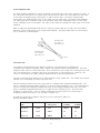
1
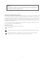
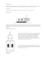
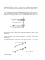
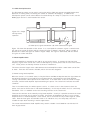
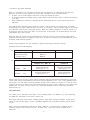
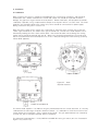
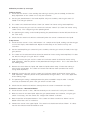
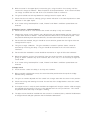
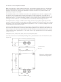
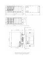
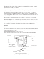
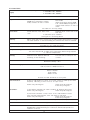
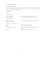
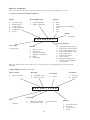
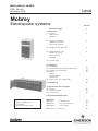
Instructions Leaflet
IP221, Rev. AA
November 2004
Level
Mobrey
Electropulse systems
Contents
Safety Information
1. Introduction
1.1 Sensors
Gap Sensors
Hi-Sens
2
1.2 Interface detection
Attenuation method
Reflection method
4
1.3 Sludge density detection
5
1.4 Head amplifier units
Normallay acting
Inverse acting
Summary
5
1.5 Control Units
6
2. Installation
2.1 Calibration
2.2 Sensor and head amplifier installation
2.3 Control Unit Installation
2.4 Wiring
Cables
Head amplifier
Control Unit
2.5 Intrinsically safe application
3
7
10
12
12
15
3. Fault Finding
16
4. Specification and description
4.1 Sensors
4.2 Head amplifiers
4.3 Control Units
17
17
18
5. Recommended Spare Parts
For instructions specific to units
used in hazardous area
installations
refer to leaflet IP221/SI
Appendices
Appendix I
Appendix II
Appendix III
Part Numbers
List of illustrations
List of tables
Maintenance / Inspection
www.mobrey.com
1
20
22
22
23
Warning :
If this equipment is used in a manner not specified by the manufacturer, the protection
provided may be impaired. All installation and commissioning of this equipment must be
carried out by electrically competent persons.
Protection of permanently installed equipment :
This equipment is regarded as permanently installed equipment. Ensure wiring is suitable for the load
current and the insulation is suitable for the voltage, temperature and environment of the installation.
A supply disconnection device must be included in the installation, fitted as close as practical to and
not be obstructed by the equipment. It must be double pole and marked as the disconnection device.
Each relay circuit must be protected by a fuse not exceeding the maximum rated current for the relay
as specified in the manual.
On wall mount unit disconnect supply before removing control unit from base. Control units must be
correctly assembled to achive stated IP ratings.
Explanation of symbols :
The IEC symbols used on the equipment are as follows :
!
Refer to Manual.
The Protective earth terminal must be connrected to an external Protective earthing system.
Functional earth terminal. |f this terminal is used it must be connected to an external
earthing system at the same potential as the protecive earthing system.
2
1. Introduction
The Mobrey Electropulse system is used for the detection of liquids or liquids with suspended / settled
solids. It consists of three units, a sensor, a head amplifier unit, and a control room unit.
1.1 Sensors
There are many different Mobrey sensors available, but they fall into two categories:
a) Gap sensors
Figure 1.1 - Gap sensor, cut away to show construction
Gap sensors feature two ultrasonic transducers mounted one either side of the gap. When immersed in a
liquid the signal transmitted is carried by the liquid across the gap, to the receiver, when the liquid level
drops below the sensor, the signal cannot be carried across the gap, and is not received by the second
transducer.
b) Hi-Sens cylindrical sensors
The Hi-Sens sensor consists of two ultrasonic transducers mounted
on the inside of a cylinder. When the sensor is not submersed in
the liquid the signal from one transducer resonates round the
cylinder like a bell ringing. If the liquid rises up around the
sensor, this ringing is damped and the signal received by the
second transducer is significantly reduced. This reduction is
monitored by the head amplifier unit. Switching occurs when the
liquid is about half way up the cylinder.
Use of Hi-Sens transducers in high alarm applications, and gap
sensors in low level alarm applications achieves a Failsafe system
in which any sensor or cable failure will be indicated as a fault or
an alarm by the control unit.
Figure 1.2 - Hi-Sens, cutaway to show
construction
3
1.2 Interface detection
Attenuation method – Figure 1.3
Attenuation is the reduction in strength of the ultrasonic signal caused by its transmission through a
liquid. Viscous liquids, emulsions and liquids containing solid particles have a greater attenuation
than clear thin liquids. Usually the difference in attenuation between the two liquids is sufficient and
the attenuation method can be used to determine which liquid is in the sensor gap. In this case the
gain of the control unit is set so that the relay is energised only when the liquid with the lower
attenuation is in the gap. For this application Sensor Type 402S is used horizontally. The heavy-duty
sensor type 433S may also be used, perhaps from above on an extension tube. For use in pipes, the
sensor pair 442S should be mounted in line, facing one another, generally horizontally across the
diameter, to detect the interface or presence of liquid. As an example, the interface between oil and
water can be detected using this method.
OIL
Transmitter Crystal
Receiver Crystal
Sensor in Oil. The ultrasonic beam is
attenuated and will not reach the
receiver crystal.
Figure 1.3 - Attenuation Method
WATER
Receiver Crystal
Transmitter Crystal
Sensor in Water. The ultrasonic beam
reaches the receiver crystal.
Reflection Method – Figure 1.4
If the attenuation’s are similar and the attenuation method does not work, then the reflection method
must be used.
If an ultrasonic beam is transmitted from one liquid to another at a suitable angle, it does not go
straight through the interface, but is bent, so that it does not reach the receiver crystal. If there is no
interface in the gap, but only one liquid, then the beam travels in a straight line, is received and the
relay energised.
For this application the sensor must be mounted at about 10º from the horizontal, as shown in Figure
1.4. Note that this method gives an alarm only when the reflective surface of the interface itself is at
the sensor.
Oil
Water
Sensor in lower liquid. The ultrasonic
beam reaches the receiver crystal.
Figure 1.4
Oil
Water
Receiver
Crystal
Transmitter
Crystal
Sensor at interface level. The ultrasonic
beam is reflected/refracted and will not
reach the receiver crystal.
In order to differentiate between two liquids, interface sensors have a large gap (usually 150mm) and
oscillate at 3.75MHz.
4
1.3 Solids Density Detection
The Electropulse system can be used in conjunction with a 433S type sensor to provide blanket level
detection in settling tanks, facilitating the control of automatic de-sludging. In addition the
Electropulse system can be used to detect the solids density of a slurry in a pipe line. In this case the
Mobrey pipe section is used instead of the sensor.
Figure 1.5 - Sludge
density sensor,
operation
(a) Clear liquid, signal transmitted (b) Solids attenuate the signal
Figure 1.5 shows the operation of the sensor. In a clear liquid the ultrasonic signal is carried across
the gap so the sensor oscillates and the control unit gives a ‘Normal’ indication. When a sludge is
present this scatters the signal as shown in Figure 1.5(b) The signal is attenuated, and the control
unit gives an alarm indication.
1.4 Head Amplifier Units
The head amplifier is mounted on the end of, or near to the sensor. It converts the low level high
frequency signal of the sensor into a series of low frequency current pulses that are sent to the control
unit. These pulses are virtually immune to electrical interference.
This means that the length of the cable between the head amplifier and the control room can be 1km
or more. There are five versions available, which fall into two categories:
i) Normal acting head amplifiers
When the sensor is in its normal state (i.e. Dry for Hi-Sens and Wet for Gap Sensors) the signal from the
transmitting transducer is received by the second transducer, and fed back to the head amplifier
causing it to transmit current pulses to the control unit. If an alarm state occurs the sensor no longer
oscillates, and the head amplifier stops transmitting the pulses. The control unit indicates the alarm
condition.
Thus in the normal state, the whole system is active. If a fault occurs in the electronics then the
pulses cease and an alarm state is indicated immediately. In this way the whole circuit is continually
monitored. This is in addition to the fault checking facilities of the control unit.
There are four versions of the normally acting head amplifier. Usually it is possible to mount the head
amplifier on the sensor, but it may be necessary for reasons of temperature or space, to use a head
amplifier which is mounted adjacent to the sensor, and is connected to it by a short length of coaxial
cable. Both of these types are available either in an industrial case, or a heavy-duty case that is
suitable for open deck mounting in marine applications.
The sensor mounted marine head amplifier may contain a double circuit board for use with dual HiSens or gap sensors.
5
ii) Inverse acting head amplifiers
When it is required to use a Hi-Sens sensor for low level detection, or a Gap Sensor for high level
detection, an inverse acting amplifier must be used. Examples of this are given below:
•
Hi-Sens can be used to detect low levels in very light liquids or foams.
•
A miniature Gap Sensor 366S, may be used to detect high level when there is insufficient room for
a Hi-Sens.
•
High temperature, corrosive, or aerated liquids, where Gap Sensor can be used at high level if
required.
The head amplifier transmits pulses when the sensor is not oscillating (its normal state), and stops
transmitting in the alarm condition when the sensor is oscillating. Thus the normal light on the control
unit indicates a wet Hi-Sens, or dry gap sensors. When the inverting amplifier is used the sensor is in
its quiescent state for most of the time. For this reason sensor cables can be monitored to check for
cable breaks with some sensors.
Note that when an inverse acting head amplifier is used the sensor is not oscillating under normal
conditions and therefore the integrity is not as high as that of a normally acting head amplifier, which
should be used wherever possible.
Inverse acting amplifiers are only available in adjacent mounting industrial housings.
Summary of sensor head amplifiers
1.1
Type
Sensor mounting
Adjacent mounting
Inverse acting
1.2
Sensor State
Hi-Sens
Dry
Lo-Sens
Hi-Sens
Wet
Wet
Lo-Sens
Dry
Industrial Case
***S*PI***
MEP*AI
MEP*XI
Marine
***S*PM***
-
Output
Normally acting head
amplifier *PI*, *PM*, AI
Normal State
Pulses transmitted
Green light on c.u.
Alarm State
No Pulses transmitted
Red light on c.u.
Inverse acting head
amplifier XI
Alarm State
No Pulse transmitted
Red light on c.u.
Normal state
Pulses transmitted
Green light on c.u.
Sensor cable check circuitry is built into the industrial adjacent mounted head amplifiers, where the
coaxial cable linking head amplifier and sensor may be exposed on site. This is only operable where
the sensor in use has Earth continuity between the two coaxial cables, see section 2.2 Lack of screen
continuity along these cables causes the head amplifier to signal a fault condition to the control room
readout unit. To use the facility a wire link in the head amplifier must be cut during installation.
(See section 2.2)
1.5 Control Units
The control unit is available in two forms, a free standing plastic case (MEP*L), or a rack mounting
unit (MEP*R). Operation is the same in either case.
Front panel indicators show normal condition (green), alarm (red), and fault (amber). A front panel
switch to test fault and alarm circuits is provided, together with a variable time delay for the alarm
circuit.
Relay contacts are provided to indicate an alarm condition. A second relay is supplied on rack
mounting control units to indicate a fault. On both units, a fault also causes an alarm to be
indicated.
6
2. Installation
2.1 Calibration
When installing the sensor, it should be remembered that it is measuring instrument, and should be
treated with care. Before installation the sensor and control unit should be inspected for transit
damage, the gap faces of gap sensors must be parallel. Before installation, the equipment should be
calibrated, if possible, using a representative sample of the liquid in which it is to be used. The head
amplifier unit should be wired to the control unit, which should be connected to its power supply.
Wiring instructions are given in section 2.4.
When the mains supply to the control unit is switched on, either the green ‘normal’ light or the red
‘alarm’ light should be on, the amber ‘fault’ light should be off. The lid of the head amplifier unit is
removed by undoing the four screws or Allen bolts. Care should be taken not to damage the sealing
gasket, which should be replaced with the lid. When using integral head amplifiers, the sensor must
not be unscrewed from the head amplifier unit as this is likely to damage the internal wiring (and may
violate ATEX approval).
i) ***S*PI
ii) ***S*PM
Figure 2.1 - Head
amplifier internals
iii) MEP*AI and MEP*XI
The marine head amplifier ***S*PM has one gain potentiometer for each sensor attached. It is factory
calibrated for the side range of liquids carried on tankers. It is advisable to check the function of the
system before final installation, using a sample of the liquid. The gain potentiometers are covered by
a screw cap, which should be replaced after re-calibration.
The industrial head amplifiers ***S*PI, MEP*AI and MEP*XI have a gain switch, which is illustrated in
Figure 2.2 (i) and 2.2 (iii).
7
Calibration procedure by sensor type
i) Hi-Sens Sensors
1) Ensure that the sensor is clean and dry, that nothing is touching the sensor body, and that the
delay adjustment on the control unit is fully anti-clockwise.
2)
Set the gain potentiometer in the head amplifier fully anti-clockwise, and the gain switch (if
fitted) in the low gain position.
3)
The control unit should now indicate ‘alarm’ (or ‘normal’ for inverse acting head amplifiers).
4)
Gradually increase the gain until the control unit indicates ‘normal’ (or ‘alarm’ for inverse acting
control units). This is beginning of the operating band.
5)
The optimum gain setting can be found by rotating the potentiometer a further 30º (one division on
the clock face),
6)
Check that the control unit switches satisfactorily when the sensor is immersed in the liquid.
ii) Gap Sensors
1) Ensure that the sensor is clean, and immerse it in a sample of the liquid, making sure that the gap
is full of the liquid, and unobstructed. Adjust the time delay on the control unit fully anticlockwise.
2)
Set the head amplifier gain control fully anti-clockwise, with the gain switch (if fitted) in the high
gain position.
3)
The control unit should now indicate alarm (or normal for inverse acting head amplifiers) if it does
not switch to low gain (if a gain switch is fitted).
4)
Gradually increase the gain until the control unit indicates normal (or alarm for inverse acting
head amplifiers). Note the position of the potentiometer and gain switch. This is the lower end of
the working range.
5)
Remove the sensor from the liquid, and allow the liquid to drain away. Ensure that nothing is
touching the sensor body. The control unit should now indicate alarm (or normal for inverse
acting head amplifiers).
6)
Gradually increase the gain until the control unit indicates normal (or alarm for inverse acting
head amplifiers). Note the position of the potentiometer and gain switch. This is the upper limit
of the working range.
7)
The optimum gain setting is midway between the points recorded in steps 4 and 6. It may be
necessary to estimate this point if the gain switch has been used.
8)
Check that the control unit switches correctly when the sensor is immersed in the liquid.
iii) Interface Sensors – Attenuation Method
1) Ensure that the sensor is clean, and that the delay on the control unit is fully anti-clockwise.
2)
With the sensor in the lower liquid adjust the gain potentiometer anti-clockwise, using the gain
switch if necessary, until the control unit changes from ‘Normal’ to ‘Alarm’.
3)
Note the position of the potentiometer. If the control unit does not switch to ‘Alarm’ use the
bottom end of the scale as a reference.
4)
Immerse the sensor in the upper liquid. The control unit should now indicate ‘Alarm’. If it does
not then the reflection method should be used.
8
5)
With the sensor in the upper liquid, increase the gain, using the switch if necessary, until the
control unit changes to ‘Normal’. Note the position of the potentiometer. If the control unit does
not change to normal then the end of the scale should be used as a reference.
6)
The gain should be set half way between the settings found in steps 3 and 5.
7)
Check that the unit switches correctly giving a normal indication in the lower liquid and an alarm
indication in the upper liquid.
8)
If an inverse acting head amplifier is used, ‘Normal’ and ‘Alarm’ conditions quoted above are
reversed.
iv) Interface Sensors – Reflection Method
1) Check that the sensor is clean and that the control unit delay is fully anti-clockwise.
2)
Immerse the sensor in each liquid in turn, adjusting the gain potentiometer until the control unit
changes from ‘Alarm’ to ‘Normal’. Note the position at which this occurs for both liquids. If the
two positions differ by more than two divisions, the attenuation method can be used.
3)
For the reflection method, the gain should be set one division greater than the higher of the two
settings found in step 2.
4)
This gives a rough calibration. The gain should be increased if spurious alarms cannot be
overcome by increasing the delay. The gain should be decreased if the unit fails to detect
interfaces.
5)
For the reflection method the sensor should be mounted at an angle of 10º to the horizontal.
6)
Where the interface consists of an emulsion layer, the sensor functions as the reflection method,
giving an ‘Alarm’ condition only at the interface, but in this case, it is not necessary to angle the
sensor at 10º.
7)
If an inverse acting head amplifier is used, ‘Normal’ and ‘Alarm’ conditions quoted above are
reversed.
v) Sludge Sensor
1) Ensure that the control unit delay is set fully anti-clockwise.
2)
When used with a 433S type sensor, the sensor should be positioned at the top of the sludge
blanket during calibration.
3)
The gain can now be adjusted until the control unit changes state with the sensor in this position.
4)
Check that raising and lowering the sensor into and out of the sludge blanket causes the control
unit to switch.
5)
If the pipe section is used, the tank should be de-sludged until the pipe contains solids at roughly
the required switching point. The gain is then adjusted until the unit just switches. This should
only be done when the slurry in the pipe is flowing.
6)
The pipe section should be installed with the sensors in a horizontal plane, and with 10 diameters
of straight unrestricted pipe upstream and six diameters downstream.
9
2.2 Sensor and head amplifier installation
Make sure that there is room inside the tank for the sensor without anything touching it, and that the
gap is not obstructed. At least an inch of clearance must be left around Hi-Sens senors. The head
amplifier should have its cable glands downwards if possible to reduce the possible to reduce the
possibility of ingress of rainwater.
For threaded sensors a hole is drilled in the tank at the appropriate level, and this is tapped to take
the sensor. On thin walled tanks it may be necessary to fit a boss to the tank. Use PTFE tape or
similar to seal the thread so that the sensor does not have to be over-tight for a good seal, as this may
damage the sensor. The sensor should be screwed in using a spanner on the hexagonal fitting, not by
turning the sensor head unit. It is assumed that the sensor will be earthed through the tank.
For flanged sensors, arrange a suitable counter flange, and fit using a gasket, tightening the bolts
evenly. If possible the bridge of sensors 302S and 402S should be to the side of the gap, and not above
or below it, and all gap sensors should have their gaps vertical. This is so that any sludge in the tank
cannot settle on the faces of the sensor.
Interface probes 402S and 433S may be mounted at an angle of 10º to the horizontal so that they can
be used in either attenuation or reflection mode. Mounting details for the adjacent head amplifier are
shown in Figure 2.3. Both model types MEP*AI and MEP*XI adjacent mounted amplifiers have a sensor
cable continuity check system built in. This cable check is only operative when one of the following
sensors is in use.
30HS, 302S, 312S, 312SP, 323S, 352S, 362S, 373S, 393S, 402S, 433S
24.0
56.0
The cable check circuit is activated by breaking Link 3, positioned next to the A & B terminals. (See
Figure 2.1)
4 FIXING HOLES
Ø 4.5mm
120.0
15.0
90.0
OF FIXING HOLES
110.0
OF FIXING HOLES
25.0
122.0
Figure 2.2 - Adjacent head
amplifier mounting details
44.0
32.0
10
* DIN RAIL Mounting Clip available on request
Figure 2.3 - Control unit mounting details
11
2.3 Control unit installation
The control units should be installed in an area suitable to their specifications. They are designed to
be used indoors, but could be installed outside using a suitable weatherproof enclosure. The front
panel should be accessible to the operator.
The standard control unit MEP*L is installed by undoing the two screws on the top and bottom of the
unit, and removing the base. This can now be mounted as required, making sure that the connection
terminals are on the left-hand side of the base.
The 19” rack unit should be mounted in a suitable cabinet in the usual fashion. It accepts up to
fourteen rack modules to type MEP*R. It should be noted that I.S. control units MEP3R will only fit
into an I.S. rack MEP3B and that the rack is included in the approval. Mounting details are shown on
the previous page.
Allow at least a 50mm gap between each rack on multiple rack installations to allow air circulation.
On installations of multi-rack systems, the fitting of a cabinet air circulating fan is recommended.
Wires to the MEP*B rack units are connected to the terminal blocks mounted on the rear panel of the
rack. In the factory the modules are fitted starting from the left hand side when viewed from the front
of the rack. If desirable, the connectors and modules can be repositioned in the rack. To assist with
cable wiring, the connector block wire access faces the rear of the rack and the screw terminals are
therefore angled. To fit cable to the 5 modules closest to the right hand end of the rack (numbers 1014) it is necessary to release the connector and rotate it slightly to allow screwdriver access.
2.4 Wiring
i) Cable
The connection from amplifier to the control unit should be made with two-core twisted pair instrument
cable with overall screen. The cores should be at least 0.5mm2 and the cable length not more than 1
km, the screen may be omitted on cable runs of 10m or less, provided that the installation will not be
subject to excessive electrical noise.
A summary of wiring arrangements is shown in figure 2.4.
Please consult the factory if this specification does not cover your needs, and for recommended
cables.
Sensor
Control unit
Head amplifier
N.B. Relays are
shown in their
‘normal’
operating states
Supply
Do not connect
screen
Protective
earth
Alarm relay
35m *Max
(cable supplied with sensor)
MEP*A* and MEP*X*
only
Fault relay
(MEP*R only)
1km max.
N.B. Control unit contacts
may not be in the order
illustrated
Connect screen at
this end only
* 15 max on i.s. systems
Cores
Min. area 0.5mm2
Max loop Impedance 35Ω
SECTION THROUGH CABLE
Outer Sheath
Screen
Inner Sheaths
Refer to section 2.5 for I.S. requirements
Figure 2.4 - Wiring summary for illustration only
12
ii) Head Amplifier Unit
The head amplifier terminals A+ and B- should be connected to the cores of the control unit cable. In
the case of the dual marine unit, lower sensor connections A+ and B- are connected to the two cores
of one cable, and upper sensor connections, C- and D+ to the other. The screen should not be
connected in any head amplifier unit, as this could cause an earth loop. The marine head amplifier
has cable grips which should be used. Care should be taken not to overtighten these, as this could
result in damage to the circuit board. The cable is then taken out through the cable entry in the head
amplifier.
When an adjacent head amplifier (AI or XI) is used, the sensor cable pins 1 and 2 are connected to
terminals 1 and 2 respectively in the sensor head amplifier. The green earth wires are connected to
the ‘E’ terminals, as shown below.
Red wire with
No 1 tag to 1
green wire to E
.
Red wire with
No. 2 tag to 2
green wire to E
To sensor
Figure 2.5
iii) Control unit
The system is designed to be noise immune; however, it is good practice to separate the
instrumentation cables from power cables. Figure 2.6 shows the terminal arrangements. The head
amplifier cable cores are connected to the + and – terminals on the control unit, ensuring that +A and
+D is connected to the + terminal, and –B or –C respectively is connected to the – terminal. The
screen is connected to the “SCN” terminal marked sensor on the rack-mounted unit.
The main connections are made to the L and N terminals of the control unit. The control unit must be
earthed, this is mandatory on intrinsically safe units.
The free standing control unit has one relay, which is a double pole changeover (DPCO) relay. This
relay is normally energised and will release if an alarm or fault condition occurs. The rack-mounting
unit has a single pole changeover (SPCO) fault relay, and an SPCO or DPCO alarm relay. The alarm
relay is normally energised and releases if an alarm or fault condition occurs. The fault relay
energises if a fault occurs. Thus in ‘normal’ mode with the green light on, the alarm relay is
energised, and the fault relay is not, as shown in Figure 2.4.
An HBC fuse should be included in the relay circuit as specified in Table 2.1.
All fuses are 20mm x 5mm
Control
Unit
Relay
Relay contact
rating (each)
Maximum fuse rating
at 240V
at 120V
MEP3R/*D
DPCO
45VA
400mA
200mA
MEP3R/*S
SPCO
500VA
4A
2A
MEP3L/*D
DPCO
500VA
4A
2A
Table 2.1 - Relay Ratings
13
MEP 3B
I.S.
To head
amplifier
Screen to be
connected
Relays
Protective
Earth
Neutral
Live
MEP 3L
I.S.
Figure 2.6 - Control Unit Connections
14
Supply
2.5 Intrinsically safe installation
Control units type MEP3* and head amplifier units to type MEP3** and ***S*P*H** are approved by
ATEX as intrinsically safe equipment to II 1 G Ex ia IIC. Refer to safety instruction IP221/SI and local
code of practice.
The following points must be noted when installing these units:i) The cable from the head amplifier to the control unit must be screened, and the screen must be
connected at the control unit end only.
ii)
On I.S systems the cable from sensor to head amplifier must be less than 15 meters long. If more
than 3 meter is required, special cable must be used.
iii) The control unit must be earthed using at least 4mm2 wire. All screen earth and main earth
connections must be commoned. In the case of the rack unit, MEP3B, the chassis must be
earthed and each unit connected independently to the chassis earth.
iv) I.S. cables must exit the control separately from the mains and relay cables.
v)
It is the responsibility of the installer to ensure that local codes of practice are followed.
Intrinsically Safe Electropulse is approved by ATEX & standards EN50014 and EN50020.
The certificates are listed below:
Description
Certificates of Conformity
Approval
Code
To Standard
MEP3 L
MEP3 R/MEP3 B
II (1) G [EExia] IIC
EN 50014 & EN 50020
Sensor & Head Amplifier
II 1 G EExia IIC T4
EN 50014 & EN 50020
Adjacent Amplifier
II 1 G EExia IIC T4
EN 50014 & EN 50020
Sensors (separate)
II 1 G EExia IIC T4
EN 50014 & EN 50020
Table 2.2 - Approvals
15
3. Fault Finding
If the unit does not work as described in the text, this section suggests some simple checks which will
rectify most faults. If the system still ceases to work or there is any doubt as to its working, the factory
should be consulted. IT SHOULD BE NOTED THAT SOME OF THE TESTS BELOW VIOLATE I.S.
REQUIREMENTS AND SHOULD NOT BE ATTEMPTED ON I.S INSTALLATIONS. If in doubt please contact
the factory.
The first test is always to check the mains supply voltage. The correct supply voltage is written on the
circuit board, and is easily checked. Connecting a unit to the wrong voltage will at best prevent it from
working, and at worst cause irreparable damage. It is also useful if possible, to exchange the control
unit for another which is known to be working, being careful to check that they both run at the same
voltage. This is a simple matter as both types of control unit unplug from their connections.
The following is a list of common faults and suggested remedies. Make sure when fault finding that
the control units are connected to the correct head amplifier.
Possible faults and suggested remedies:
No front panel lights lit
i) Check that mains is connected and switched on.
ii) Check the fuse, and replace if necessary. The part numbers for fuses are:
• All rack modules
- H1525 (F 500mA HBC)
• Free standing unit 240V
- K1793 (T 63mA, 35A Breaking capacity)
• Free standing unit 120V
- K1796 (T 125mA, 35A Breaking capacity)
All fuses are 5mm x 20mm IEC 127.
Fault indicated
i) Check for short circuits between the head amplifier cable cores, or open circuits. Disconnect the
cable from the control unit, and measure the resistance between the two wires to the head
amplifier. The resistance should be a little over 100K ohm in one direction, and about 3.5K ohms
to 50k ohms in the other with the head amplifier connected depending on the meter used. Check
that the resistance between either core and the screen is at least 2M ohm when the screen is
disconnected at both ends.
ii)
Excessive current causes a fault alarm. The head amplifier usually consumes 12-16mA. This is
measured by disconnecting one of the head amplifier terminals, and connecting a millammeter
between the head amplifier terminal and the end of the wire. Reconnect the wire when this
measurement has been taken.
iii) Cable cores must be connected at both ends, and the screen must be connected at the control
unit end only.
iv) Make sure that the cable is within the specification of section 2.4 (i).
v)
Ensure that the link in the head amplifier has not been removed unless the unit is used with one
of the sensors listed in Section 2.2
Unit not switching
Recalibrate as described in Section 2.1.
Relay contacts not changing
i) If the lamps are indicating the correct status of the appropriate sensor, but the relay contacts at
the rear of the unit are apparently not changing state, check the external fuses in the relay
circuits.
ii)
Check that the relay inside the unit is switching freely.
16
4. Specification and Description
4.1 Sensors
Sensor
Type
Minimum
Temperature
ºC
Maximum
Temperature
ºC
Maximum
Pressure
Kg/cm2
Fitting
Frequency
302S
30HS
312S
312SP
323S
352S
362S
366S
373S
393S
39HS
402S
420S
433S
442S
HL*S
-70
0
-70
-70
-70
-70
-210
-210
-70
-70
0
-70
-70
-70
-70
-70
150
250
130
130
130
150
65
65
150
150
250
150
150
150
150
130
56
50
21
20
21
56
70
3.5
56
56
50
103
280
105
105
100
R¾”
R1½”
R1”
R1”
R¾”
R¾”
R¾”
M6
R¾”
R¾”
R¾”
R¾”
¾” NPT
R¾”
R¾”
Flange
or screw
1
1
1
1
1
1
3.75
3.75
1
1
1
3.75
3.75
1.20
3.75
1
* Note that 1 kg/cm2 = 100kPa
Table 4.1 - Sensor specification
4.2 Head Amplifiers
Power supply:
Normal 11.5V, 12-16mA from the control unit
Operating frequency: 1 or 3.7 MHz
Gain:
Potentiometer adjustable, switchable ranges on MEP**I
Output:
Current pulses transmitted to control unit in ‘Normal’ mode (270 Hz)
Temperature Range: -25 to 85ºC
Test Switches:
Optional: MEP* AI, ***S*PI**, ***S*PM** simulates a break in the sensor cables
(fault test)
MEP*XI simulates active sensor, stopping pulses (alarm test)
Housing:
i) ***S*PI**: IP54 Aluminium housing, mounted on sensor, Pg 16 cable entries
ii) ***S*PM**: IP68 Gunmetal or Stainless steel, mounted on sensor, M20 cable
entries, holds up to two head amplifier circuits.
iii) MEP*AI: IP65 Polycarbonate, mounted adjacent to sensor
MEP*XI
Cable:
i) Head amplifier
ii) Sensor to head
Not supplied, see Section 2.4 (i) for specification.
to control sensor
MEP* (AI, XI) only, supplied with sensors.
amplifier
Earthing:
Head amplifier must not be connected to the screen of the control unit cable.
On adjacent amplifier, the screens of the sensor cables must be connected to the
head amplifier.
Intrinsic Safety:
Units type MEP3 are intrinsically safe, see table 2.3 for certificate details
17
4.3 Control Units
Supply:
Rack Mounted Unit MEP*R
Free Standing Unit MEP*L
1: 220/240V ±10%, 50/60Hz
2: 110/120V ±10%, 50/60Hz
Power consumption:
Less than 7VA
Output:
Alarm relay
DPCO relay, energised in normal
mode, releases on fault or alarm
Connections:
Terminal block on the rear of the
Screw terminal in the base of the
rack unit.
case.
To take wires up to 1.5mm2
See Figure 2.7 for wiring details
Earthing:
Mains input and sensor connections are fully floating with respect to earth.
The earth terminal on the freestanding unit and the rack must be earthed.
Intrinsic safety:
Output to Head Amplifier:
Temperature Range:
Housing:
Less than 6VA
Fault relay: SPCO, Energises in
fault mode
Alarm relay: High current SPCO,
Low current DPCO, Energised in
normal mode releases on fault or
alarm
See Table 2.1 for relay ratings
Units MEP*L and MEP*R are intrinsically safe.
See table 2.2 for certificate details.
Approximately 11.5V 20mA maximum
-10ºC to 65ºC
The units must be left to warm up for 15 minutes before being exposed
to sub-zero temperatures.
IP20 enclosure. Optional DIN rail
mounting or wall mounting.
Maximum altitude : 2000m
Maximum humidity : 95%
Environment:
Installation Category:
19” rack unit to hold up to 14
controls.
CAT II (264V a.c. MAX) Pollution 2
CAT III (132V a.c. MAX) Pollution 2
3 LEDs
Green = Normal
Red = Alarm
Amber = Fault
Indicators:
At least one LED should be on at any time.
Fault Indication:
A fault is indicated if too much, or too little current is taken by the head
amplifier, indicating a short circuit or an open circuit.
Alarm relay de-energises
Test Switch:
Alarm Delay:
Reset:
E.M.C.
L.V.D.
Alarm relay de-energises
Fault relay energises
a) Test Alarm Simulates the alarm condition by stopping the pulses.
Alarm relay de-energises
Alarm relay de-energises
b) Test Fault simulates a short circuit in the cable between control
room and the head amplifier, fault and alarm is indicated.
Alarm relay de-energises
Alarm relay de-energises
Fault relay energises
1-10 seconds. Preset on front panel (20 turns span)
Returns to normal approx. 200ms after alarm is cleared.
BS EN61326: 1998 (Emissions) for Class B Equipment
BSEN61326: 1998 (Immunity) for continuous unmonitored operation in
industrial locations
EN61010-1
18
5. Recommended Spare Parts
5.1 Sensor and head amplifier
Sensors and head amplifiers are supplied as integral items, and therefore no spare parts are available.
In the case of sensor mounted head amplifiers, the sensor is attached to the head amplifier, and the
two are not usually available separately.
5.2 Control Units
i) Fuses
Standard Control Unit:
MEP*L/1* (220/240V)
MEP*L/2* (110/120V)
K179 T 63mA, 35A Breaking capacity (IEC 127)
K1796 T 125mA, 35A Breaking capacity (IEC 127)
Rack Mounted Unit:
MEP*R/** All voltages
All fuses are 5mm×20mm
H1525 F 500mA, 1500A Breaking capacity (IEC127)
ii) Edge Connectors (Rack units only)
I.S. units:
MEP3R
K1806
K1805
Screws for mounting connectors
9722-827 M3 × 8mm cheese head (2 required per
connector)
Washer
9726-807 M3 (2 required per connector)
19
4 way edge connector
12 way edge connector
Appendix I - Part Numbers
Please note that the existence of a part number does not imply the availability of a unit.
1. Sensors and Sensors with Head Amplifiers
Fitting
Head Amplifier Type
Approval
0
2
3
6
8
9
P
U
O
H
L
P
S
F
Outside Fitting
Double Fitting
Inside Fitting
Inside Fitting M6
Sludge Pipe
Flange
Sensor Mounted
Adjacent Mounted
None
ATEX
Lloyds Register of Shipping
PTB
SEV
LCIE
Options
T
Test Switch
302SDP80T
Sensor Connection
Sensor Type
Material
See Catalogue
D
Y
P
J
M
C
0
1
4
5
7
8
9
M
I
J
Stainless steel
Epoxy resin
Polyether sulphone
Cryogenic Epoxy Resin
Monel
Hastelloy C
PVC Cable & Phono Plugs
PTFE Cable & Phono Plugs
PVC Cable & BNC Plugs
PTFE Cable & BNC Plugs
PVC Cable & Pins
PTFE Cable & Pins
Special Cable
Marine Head Amplifier
Industrial Head Amplifier
Junction Box
Note: Pre 1984 sensors have an M or an I in the third place to indicate Marine or Industrial head
amplifier.
2. Head Amplifiers (Adjacent mounted)
Intrinsic Safety
Mounting
3
A
X
Intrinsically Safe
Test Switch
Sensor Type
Standard acting
Reverse acting
C
T
N
Single
Included
Omitted
MEP3AI/3CAN
Electronics
Type
I
Industrial
3
4
1 MHz Switched Gain
3.7 MHz Switched
} Industrial Only
Material
A
G
S
P
20
Aluminium Alloy
Gunmetal
Stainless Steel
Plastic
3. Control Units
MEP3L/1D
Intrinsic Safety
Mounting
Mains Voltage
Output Relay
3
R
L
1 220/240
Volts
2 110/120
Volts
S
D
Intrinsically Safe
Rack Mounted
Wall Mounted
Single Pole Changeover
Double Pole Changeover
4. Racks
MEP3B/07
Intrinsic Safety
Number of spaces for control units
3
01 to 14
Remaining spaces are blanked off
Intrinsically Safe
21
Appendix II – List of illustrations
Section
Figure
Title
Page
1.
Introduction
1.1
1.2
1.3
1.4
1.5
Gap Sensor
Hi-Sens Sensor
Attenuation Method
Interface Method
Sludge Density Sensor
3
3
4
4
5
2.
Installation
2.1
2.2
2.3
2.4
2.5
2.6
Head Amplifier
Adjacent head amplifier
Control unit mounting details
Wiring Summary
Sensor connections to adjacent head amplifier
Control unit connections
7
8
11
12
13
14
Appendix III - List of tables
Section
Table
Title
Page
1.
Introduction
1.1
1.2
Head amplifier – types
Head amplifier – operation
6
6
2.
Installation
2.1
2.2
Relay ratings and fuses
Approvals
13
15
4.
Specification
4.1
Sensor specification
17
22
Maintenance / Inspection
This is limited to periodic inspection by a qualified person to ensure that the installation including
wiring and equipment housing is safe.
Clean only with a damp cloth, ensuring that no moisture enters control unit.
Check unit for damage and if damaged do not use.
23
Instructions Leaflet
IP221, Rev. AA
November 2004
Level
abcdef
The Emerson logo is a trade mark and service mark of Emerson Electric Co.
Rosemount is a registered trademark of Rosemount Inc.
Mobrey is a registered trademark of Mobrey Ltd.
All other marks are the property of their respective owners.
We reserve the right to modify or improve the designs or specifications of product and services at any time without notice.
International:
Emerson Process Management
Mobrey Measurement
158 Edinburgh Avenue,
Slough, Berks, SL1 4UE, UK
T +44 1753 756600
F +44 1753 823589
www.mobrey.com
Americas:
Emerson Process Management
Rosemount Inc.
8200 Market Boulevard
Chanhassen, MN USA 55317
T (US) (800) 999-9307
T (International) (952) 906-8888
F (International) (952) 949-7001
24