1
Installation and Operation Manual
IPmux-1, IPmux-1E
TDMoIP® Gateways
IPmux-1, IPmux-1E
TDMoIP® Gateways
Installation and Operation Manual
Notice
This manual contains information that is proprietary to RAD Data Communications Ltd. ("RAD"). No
part of this publication may be reproduced in any form whatsoever without prior written approval by
RAD Data Communications.
Right, title and interest, all information, copyrights, patents, know-how, trade secrets and other
intellectual property or other proprietary rights relating to this manual and to the IPmux-1, IPmux-1E
and any software components contained therein are proprietary products of RAD protected under
international copyright law and shall be and remain solely with RAD.
IPmux-1, IPmux-1E is a registered trademark of RAD. No right, license, or interest to such trademark is
granted hereunder, and you agree that no such right, license, or interest shall be asserted by you with
respect to such trademark.
You shall not copy, reverse compile or reverse assemble all or any portion of the Manual or the IPmux1, IPmux-1E. You are prohibited from, and shall not, directly or indirectly, develop, market, distribute,
license, or sell any product that supports substantially similar functionality as the IPmux-1, IPmux-1E,
based on or derived in any way from the IPmux-1, IPmux-1E. Your undertaking in this paragraph shall
survive the termination of this Agreement.
This Agreement is effective upon your opening of the IPmux-1, IPmux-1E package and shall continue
until terminated. RAD may terminate this Agreement upon the breach by you of any term hereof.
Upon such termination by RAD, you agree to return to RAD the IPmux-1, IPmux-1E and all copies and
portions thereof.
For further information contact RAD at the address below or contact your local distributor.
International Headquarters
RAD Data Communications Ltd.
U.S. Headquarters
RAD Data Communications Inc.
24 Raoul Wallenberg St.
Tel Aviv 69719 Israel
Tel: 972-3-6458181
Fax: 972-3-6498250
E-mail: [email protected]
900 Corporate Drive
Mahwah, NJ 07430 USA
Tel: (201) 529-1100, Toll free: 1-800-444-7234
Fax: (201) 529-5777
E-mail: [email protected]
© 1999–2004 RAD Data Communications Ltd.
Publication No. 114-200-04/04
Limited Warranty
RAD warrants to DISTRIBUTOR that the hardware in the IPmux-1, IPmux-1E to be delivered
hereunder shall be free of defects in material and workmanship under normal use and service for a
period of twelve (12) months following the date of shipment to DISTRIBUTOR.
If, during the warranty period, any component part of the equipment becomes defective by reason of
material or workmanship, and DISTRIBUTOR immediately notifies RAD of such defect, RAD shall have
the option to choose the appropriate corrective action: a) supply a replacement part, or b) request
return of equipment to its plant for repair, or c) perform necessary repair at the equipment's location.
In the event that RAD requests the return of equipment, each party shall pay one-way shipping costs.
RAD shall be released from all obligations under its warranty in the event that the equipment has been
subjected to misuse, neglect, accident or improper installation, or if repairs or modifications were
made by persons other than RAD's own authorized service personnel, unless such repairs by others
were made with the written consent of RAD.
The above warranty is in lieu of all other warranties, expressed or implied. There are no warranties
which extend beyond the face hereof, including, but not limited to, warranties of merchantability and
fitness for a particular purpose, and in no event shall RAD be liable for consequential damages.
RAD shall not be liable to any person for any special or indirect damages, including, but not limited to,
lost profits from any cause whatsoever arising from or in any way connected with the manufacture,
sale, handling, repair, maintenance or use of the IPmux-1, IPmux-1E, and in no event shall RAD's
liability exceed the purchase price of the IPmux-1, IPmux-1E.
DISTRIBUTOR shall be responsible to its customers for any and all warranties which it makes relating
to IPmux-1, IPmux-1E and for ensuring that replacements and other adjustments required in
connection with the said warranties are satisfactory.
Software components in the IPmux-1, IPmux-1E are provided "as is" and without warranty of any kind.
RAD disclaims all warranties including the implied warranties of merchantability and fitness for a
particular purpose. RAD shall not be liable for any loss of use, interruption of business or indirect,
special, incidental or consequential damages of any kind. In spite of the above RAD shall do its best to
provide error-free software products and shall offer free Software updates during the warranty period
under this Agreement.
RAD's cumulative liability to you or any other party for any loss or damages resulting from any claims,
demands, or actions arising out of or relating to this Agreement and the IPmux-1, IPmux-1E shall not
exceed the sum paid to RAD for the purchase of the IPmux-1, IPmux-1E. In no event shall RAD be liable
for any indirect, incidental, consequential, special, or exemplary damages or lost profits, even if RAD has
been advised of the possibility of such damages.
This Agreement shall be construed and governed in accordance with the laws of the State of Israel.
General Safety Instructions
The following instructions serve as a general guide for the safe installation and operation of
telecommunications products. Additional instructions, if applicable, are included inside the manual.
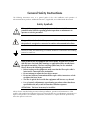
Safety Symbols
Warning
This symbol may appear on the equipment or in the text. It indicates
potential safety hazards regarding product operation or maintenance to
operator or service personnel.
Danger of electric shock! Avoid any contact with the marked surface while
the product is energized or connected to outdoor telecommunication lines.
.
Protective earth: the marked lug or terminal should be connected to the building
protective earth bus.
Warning
Some products may be equipped with a laser diode. In such cases, a label
with the laser class and other warnings as applicable will be attached near
the optical transmitter. The laser warning symbol may be also attached.
Please observe the following precautions:
• Before turning on the equipment, make sure that the fiber optic cable is
intact and is connected to the transmitter.
• Do not attempt to adjust the laser drive current.
• Do not use broken or unterminated fiber-optic cables/connectors or look
straight at the laser beam.
• The use of optical devices with the equipment will increase eye hazard.
• Use of controls, adjustments or performing procedures other than those
specified herein, may result in hazardous radiation exposure.
ATTENTION: The laser beam may be invisible!
Always observe standard safety precautions during installation, operation and maintenance of this
product. Only qualified and authorized service personnel should carry out adjustment, maintenance or
repairs to this product. No installation, adjustment, maintenance or repairs should be performed by
either the operator or the user.
Handling Energized Products
General Safety Practices
Do not touch or tamper with the power supply when the power cord is connected. Line voltages may
be present inside certain products even when the power switch (if installed) is in the OFF position or a
fuse is blown. For DC-powered products, although the voltages levels are usually not hazardous,
energy hazards may still exist.
Before working on equipment connected to power lines or telecommunication lines, remove jewelry
or any other metallic object that may come into contact with energized parts.
Unless otherwise specified, all products are intended to be grounded during normal use. Grounding is
provided by connecting the mains plug to a wall socket with a protective earth terminal. If an earth lug
is provided on the product, it should be connected to the protective earth at all times, by a wire with a
diameter of 18 AWG or wider. Rack-mounted equipment should be mounted only in earthed racks
and cabinets.
Always make the ground connection first and disconnect it last. Do not connect telecommunication
cables to ungrounded equipment. Make sure that all other cables are disconnected before
disconnecting the ground.
Connection of AC Mains
Make sure that the electrical installation complies with local codes.
Always connect the AC plug to a wall socket with a protective ground.
The maximum permissible current capability of the branch distribution circuit that supplies power to
the product is 16A. The circuit breaker in the building installation should have high breaking capacity
and must operate at short-circuit current exceeding 35A.
Always connect the power cord first to the equipment and then to the wall socket. If a power switch is
provided in the equipment, set it to the OFF position. If the power cord cannot be readily
disconnected in case of emergency, make sure that a readily accessible circuit breaker or emergency
switch is installed in the building installation.
Connection of DC Mains
Unless otherwise specified in the manual, the DC input to the equipment is floating in reference to the
ground. Any single pole can be externally grounded.
Due to the high current capability of DC mains systems, care should be taken when connecting the DC
supply to avoid short-circuits and fire hazards.
DC units should be installed in a restricted access area, i.e. an area where access is authorized only to
qualified service and maintenance personnel.
Make sure that the DC supply is electrically isolated from any AC source and that the installation
complies with the local codes.
The maximum permissible current capability of the branch distribution circuit that supplies power to
the product is 16A. The circuit breaker in the building installation should have high breaking capacity
and must operate at short-circuit current exceeding 35A.
Before connecting the DC supply wires, ensure that power is removed form the DC circuit. Locate the
circuit breaker of the panel board that services the equipment and switch it to the OFF position. When
connecting the DC supply wires, first connect the ground wire to the corresponding terminal, then the
positive pole and last the negative pole. Switch the circuit breaker back to the ON position.
A readily accessible disconnect device that is suitably rated and approved should be incorporated in
the building installation.
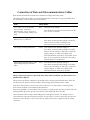
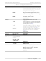
Connection of Data and Telecommunications Cables
Data and telecommunication interfaces are classified according to their safety status.
The following table lists the status of several standard interfaces. If the status of a given port differs from
the standard one, a notice will be given in the manual.
Ports
Safety Status
V.11, V.28, V.35, V.36, RS-530,
X.21, 10 BaseT, 100 BaseT,
Unbalanced E1, E2, E3, STM, DS-2,
DS-3, S-Interface ISDN, Analog voice
E&M
SELV
xDSL (without feeding voltage),
Balanced E1, T1, Sub E1/T1
TNV-1 Telecommunication Network Voltage-1:
FXS (Foreign Exchange Subscriber)
TNV-2 Telecommunication Network Voltage-2:
Safety Extra Low Voltage:
Ports which do not present a safety hazard. Usually
up to 30 VAC or 60 VDC.
Ports whose normal operating voltage is within the
limits of SELV, on which overvoltages from
telecommunications networks are possible.
Ports whose normal operating voltage exceeds the
limits of SELV (usually up to 120 VDC or telephone
ringing voltages), on which overvoltages from
telecommunication networks are not possible. These
ports are not permitted to be directly connected to
external telephone and data lines.
FXO (Foreign Exchange Office), xDSL
(with feeding voltage), U-Interface
ISDN
TNV-3 Telecommunication Network Voltage-3:
Ports whose normal operating voltage exceeds the
limits of SELV (usually up to 120 VDC or telephone
ringing voltages), on which overvoltages from
telecommunication networks are possible.
Always connect a given port to a port of the same safety status. If in doubt, seek the assistance of a
qualified safety engineer.
Always make sure that the equipment is grounded before connecting telecommunication cables. Do
not disconnect the ground connection before disconnecting all telecommunications cables.
Some SELV and non-SELV circuits use the same connectors. Use caution when connecting cables.
Extra caution should be exercised during thunderstorms.
When using shielded or coaxial cables, verify that there is a good ground connection at both ends. The
earthing and bonding of the ground connections should comply with the local codes.
The telecommunication wiring in the building may be damaged or present a fire hazard in case of
contact between exposed external wires and the AC power lines. In order to reduce the risk, there are
restrictions on the diameter of wires in the telecom cables, between the equipment and the mating
connectors.
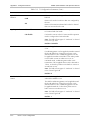
Caution
Attention
To reduce the risk of fire, use only No. 26 AWG or larger telecommunication line cords.
Pour réduire les risques s’incendie, utiliser seulement des conducteurs de
télécommunications 26 AWG ou de section supérieure.
Some ports are suitable for connection to intra-building or non-exposed wiring or cabling only. In such
cases, a notice will be given in the installation instructions.
Do not attempt to tamper with any carrier-provided equipment or connection hardware.
Electromagnetic Compatibility (EMC)
The equipment is designed and approved to comply with the electromagnetic regulations of major
regulatory bodies. The following instructions may enhance the performance of the equipment and will
provide better protection against excessive emission and better immunity against disturbances.
A good earth connection is essential. When installing the equipment in a rack, make sure to remove all
traces of paint from the mounting points. Use suitable lock-washers and torque. If an external
grounding lug is provided, connect it to the earth bus using braided wire as short as possible.
The equipment is designed to comply with EMC requirements when connecting it with unshielded
twisted pair (UTP) cables. However, the use of shielded wires is always recommended, especially for
high-rate data. In some cases, when unshielded wires are used, ferrite cores should be installed on
certain cables. In such cases, special instructions are provided in the manual.
Disconnect all wires which are not in permanent use, such as cables used for one-time configuration.
The compliance of the equipment with the regulations for conducted emission on the data lines is
dependent on the cable quality. The emission is tested for UTP with 80 dB longitudinal conversion loss
(LCL).
Unless otherwise specified or described in the manual, TNV-1 and TNV-3 ports provide secondary
protection against surges on the data lines. Primary protectors should be provided in the building
installation.
The equipment is designed to provide adequate protection against electro-static discharge (ESD).
However, it is good working practice to use caution when connecting cables terminated with plastic
connectors (without a grounded metal hood, such as flat cables) to sensitive data lines. Before
connecting such cables, discharge yourself by touching earth ground or wear an ESD preventive wrist
strap.
FCC-15 User Information
This equipment has been tested and found to comply with the limits of the Class A digital device,
pursuant to Part 15 of the FCC rules. These limits are designed to provide reasonable protection
against harmful interference when the equipment is operated in a commercial environment. This
equipment generates, uses and can radiate radio frequency energy and, if not installed and used in
accordance with the Installation and Operation manual, may cause harmful interference to the radio
communications. Operation of this equipment in a residential area is likely to cause harmful
interference in which case the user will be required to correct the interference at his own expense.
Canadian Emission Requirements
This Class A digital apparatus meets all the requirements of the Canadian Interference-Causing
Equipment Regulation.
Cet appareil numérique de la classe A respecte toutes les exigences du Règlement sur le matériel
brouilleur du Canada.
Warning per EN 55022 (CISPR-22)
Warning
This is a class A product. In a domestic environment, this product may cause
radio interference, in which case the user will be required to take adequate
measures.
Avertissement
Cet appareil est un appareil de Classe A. Dans un environnement résidentiel, cet
appareil peut provoquer des brouillages radioélectriques. Dans ces cas, il peut
être demandé à l’utilisateur de prendre les mesures appropriées.
Achtung
Dieses ist ein Gerät der Funkstörgrenzwertklasse A. In Wohnbereichen können
bei Betrieb dieses Gerätes Rundfunkströrungen auftreten, in welchen Fällen der
Benutzer für entsprechende Gegenmaßnahmen verantwortlich ist.
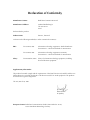
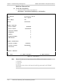
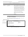
Declaration of Conformity
Manufacturer's Name:
RAD Data Communications Ltd.
Manufacturer's Address:
24 Raoul Wallenberg St.
Tel Aviv 69719
Israel
declares that the product:
IPmux-1, IPmux-1E
Product Name:
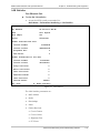
conforms to the following standard(s) or other normative document(s):
EMC:
Safety:
EN 55022 (1998)
Information technology equipment – Radio disturbance
characteristics – Limits and methods of measurement.
EN 55024 (1998)
Information technology equipment –Immunity
characteristics – Limits and methods of measurement.
EN 60950/A4 (1996)
Safety of information technology equipment, including
electrical business equipment.
Supplementary Information:
The products herewith comply with the requirements of the EMC Directive 89/336/EEC and the Low
Voltage Directive 73/23/EEC and the R & TTE directive 99/5/EC for wired equipment. The products
were tested in a typical configuration.
Tel Aviv, March 18, 2001
Haim Karshen
VP Quality
European Contact: RAD Data Communications GmbH, Otto-Hahn-Str. 28-30,
85521 Ottobrunn-Riemerling, Germany
Preface
Foreword
This manual describes the technical characteristics, applications, installation and operation of
IPmux-1 and IPmux-1E. In this manual the products will be referred to as IPmux-1/1E.
Manual Organization
This manual is organized as follows:
Chapter 1. Introduction
presents the main features versions, applications, functional description, and lists the
technical specifications of IPmux-1/1E.
Chapter 2. Installation
provides detailed installation and operation instructions for IPmux-1/1E.
Chapter 3. Operation
provides general instructions for getting started, managing IPmux-1/1E by means of terminals
and Telnet hosts, and provides typical configuration procedures.
Chapter 4. Tests and Diagnostics
describes the diagnostic and performance monitoring functions supported by IPmux-1/1E.
Appendix A. Boot Sequence for Downloading Software
provides instructions for the installation of new software releases.
Appendix B. Telnet
details management by Telnet.
Appendix C. SNMP Management
describes the SNMP and IP environments, and provides background information regarding
the handling of management traffic.
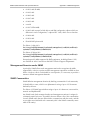
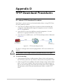
Appendix D. TFTP Download Procedures
details management by Telnet.
Appendix E. Parameters and Screens
describes the configuration screens and parameters.
Conventions
Note
A note draws attention to a general rule for a procedure, or to exceptions to a rule.
Caution
A caution warns of possible damage to the equipment if a procedure is not
followed correctly.
Warning
A warning alerts to the presence of important operating and maintenance
(servicing) instructions in the literature accompanying the equipment. If these
instructions are not followed exactly, possible bodily injury may occur.
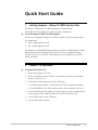
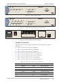
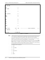
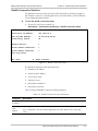
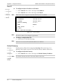
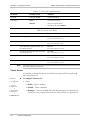
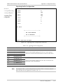
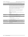
Quick Start Guide
1.
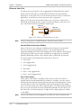
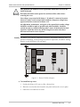
Setting Jumpers – IPmux-1E ISDN Version Only
The IPmux-1E ISDN version contains jumpers for phantom feed.
Other IPmux-1/1E models do not require jumper configuration.
To set the IPmux-1E ISDN-S module jumpers:
If necessary, change the settings in accordance with the specific requirements of
your application:
•
ENA – enable phantom feed
•
DIS – disable phantom feed.
The phantom feed ENA/DIS setting influences the IPmux-1E BRI operation mode.
When phantom feed is disabled, the S-interface can be configured (through
software) to the TE or NT mode. When phantom feed is enabled, only the NT
mode is possible.
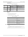
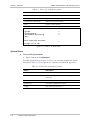
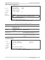
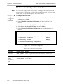
2.
IPmux-1/1E Operation
To operate the IPmux-1/1E:
1. Power up the IPmux-1/1E unit.
2. Connect an ASCII terminal to IPmux-1/1E control port (IPmux-1/1E default
setting: 19200, N, 8, 1).
3. Verify IPmux-1/1E startup by one of the following:
From the ASCII terminal, verify that the Self-Test has ended successfully.
Check the RDY LED on the on the left side of the front panel of the unit.
4. Connect the Ethernet link cable to the network port (connect an Ethernet link
to the user port if the model includes one) and check the Sync LED.
5. Connect TDM cables to the TDM port.
6. Log in to the system software.
IPmux-1/1E Operation
1
IPmux-1/1E Installation and Operation Manual
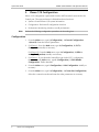
Quick Start Guide
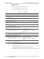
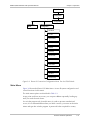
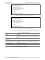
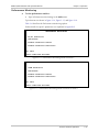
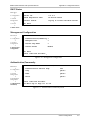
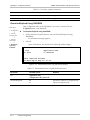
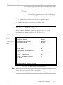
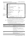
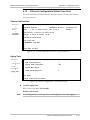
3.
IPmux-1/1E Configuration
IPmux-1/1E configuration is performed from the ASCII terminal connected to the
Control port. The system software is divided into three functions:
Note
•
System: General IPmux-1/1E system information.
•
Configuration: Performs all configuration functions
•
Performance Monitoring: Monitors overall performance
Perform the following configuration procedures in the order given.
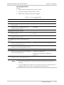
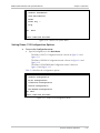
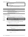
Configuration
1. From the Main menu, type 2 (Configuration), 1 (General Configuration)
1 (Host IP). Enter the Host IP parameters.
2. For IPmux-1: From the Main menu, type 2 (Configuration), 2 (E1/T1)
Configuration. Modify as necessary.
For IPmux-1E: From the Main menu, type 2 (Configuration), 2 (ISDN or
Analog Configuration). Modify as necessary.
3. For IPmux-1: If you selected a framed line type in the E1/T1 configuration,
then the from the Main menu, type 2 (Configuration), 5 (DSO Bundle
Configuration). Define timeslots.
4. From the Main menu, type 2 Configuration, 4 LAN Configuration. Modify as
necessary.
5. From the Main menu, type 2 (Configuration), 3 (Connection Configuration).
Select the connection mode and enter the other parameters as necessary.
2
IPmux-1/1E Configuration
Contents
Chapter 1. Introduction
1.1 Overview..................................................................................................................... 1-1
Versions................................................................................................................................ 1-1
Applications.......................................................................................................................... 1-2
Features................................................................................................................................ 1-5
1.2 Physical Description..................................................................................................... 1-8
1.3 Functional Description................................................................................................. 1-9
Operation Modes ............................................................................................................... 1-10
Timeslot Assignment in a Bundle......................................................................................... 1-12
Bundle Redundancy ........................................................................................................... 1-12
Testing................................................................................................................................ 1-14
Timing Modes..................................................................................................................... 1-14
Network Timing Schemes ................................................................................................... 1-15
Frame Format ..................................................................................................................... 1-16
Packet Delay Variation........................................................................................................ 1-18
PDVT (Jitter) Buffer ............................................................................................................. 1-19
Ethernet Throughput........................................................................................................... 1-20
Round Trip Delay ...............................................................................................................1-22
Reorder and Duplication of Ethernet Frames ....................................................................... 1-23
OAM Connectivity .............................................................................................................. 1-24
End-to-End Alarm Generation ............................................................................................. 1-24
VLAN Traffic Behavior ........................................................................................................ 1-25
Ethernet User Port .............................................................................................................. 1-26
DHCP ................................................................................................................................ 1-32
1.4 Technical Specifications............................................................................................. 1-33
Chapter 2. Installation
2.1 Site Requirements and Prerequisites ............................................................................ 2-1
2.2 Package Contents ........................................................................................................ 2-2
2.3 Installation and Setup .................................................................................................. 2-2
Setting Internal Jumpers ........................................................................................................ 2-2
Connecting Interfaces and Cables..........................................................................................2-4
Connecting the Power .......................................................................................................... 2-7
Chapter 3. Operation
3.1 Front Panel Controls, Connectors, and Indicators......................................................... 3-1
3.2 Operating Instructions ................................................................................................. 3-3
Turning IPmux-1/1E On ........................................................................................................ 3-3
Login .................................................................................................................................... 3-4
Turning IPmux-1/1E Off ........................................................................................................3-4
3.3 Getting Started............................................................................................................. 3-5
3.4 Overview of Menu Operations .................................................................................... 3-5
Navigating ............................................................................................................................ 3-5
Main Menu......................................................................................................................... 3-11
System Menu...................................................................................................................... 3-12
Setting IPmux-1/1E Configuration Options........................................................................... 3-13
Performance Monitoring ..................................................................................................... 3-15
IPmux-1/1E Installation and Operation Manual
i
Table of Contents
Chapter 4. Troubleshooting and Diagnostics
4.1 Error Detection ............................................................................................................ 4-1
Using Front Panel LEDs......................................................................................................... 4-1
Working with the Alarm Buffer.............................................................................................. 4-1
4.2 Troubleshooting........................................................................................................... 4-4
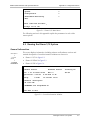
4.3 Performance Monitoring and Troubleshooting Statistics ............................................... 4-5
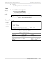
E1/T1 Statistics...................................................................................................................... 4-5
LAN Statistics ...................................................................................................................... 4-11
Bundle Connection Statistics ............................................................................................... 4-17
4.4 Diagnostic Tests ......................................................................................................... 4-23
E1/T1.................................................................................................................................. 4-23
ISDN BRI............................................................................................................................ 4-24
FXS/FXO/E&M ....................................................................................................................4-24
4.5 Frequently Asked Questions ...................................................................................... 4-25
Appendix A. Boot Sequence for Downloading Software
Appendix B. Telnet
Appendix C. SNMP Management
Appendix D. TFTP Download Procedures
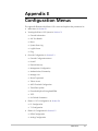
Appendix E. Configuration Menus
ii
IPmux-1/1E Installation and Operation Manual
Table of Contents
List of Figures
1-1. Multiplexing Voice and Data over an IP/Ethernet Link ........................................................... 1-2
1-2. E1/T1 Circuit Extension over an IP/Ethernet Network............................................................. 1-3
1-3. Analog Voice Application ...................................................................................................... 1-3
1-4. Digital ISDN Application (V5.1 Concentration of Remote BRIs) ............................................. 1-4
1-5. Extending ISDN BRI Ports of a Small Office ........................................................................... 1-4
1-6. Ethernet-based Multi-tenant Application with Voice and Data Integrated Access ................... 1-5
1-7. IPmux-1/1E 3D View............................................................................................................. 1-8
1-8. IPmux-1 E1/T1 Point-to-Point Application ............................................................................. 1-9
1-9. Grooming of Timeslots from Remote Sites into a Single E1/T1 Port at Central Site.................. 1-9
1-10. Timeslot Assignment in a Bundle, for IPmux-1E/ISDN........................................................ 1-12
1-11. Bundle Redundancy Application (A) .................................................................................. 1-13
1-12. Bundle Redundancy Application (B) .................................................................................. 1-13
1-13. IPmux-1 in Loopback Timing Mode................................................................................... 1-15
1-14. IPmux-1 in External Clock Mode ....................................................................................... 1-15
1-15. IPmux-1 in Adaptive Timing Mode .................................................................................... 1-16
1-16. IPmux-1E in Adaptive Timing Mode .................................................................................. 1-16
1-17. TDMoIP® Frame Structure................................................................................................ 1-17
1-18. VLAN Tag Format (802.1p&Q) .......................................................................................... 1-18
1-19. Packet Delay Variation ...................................................................................................... 1-19
1-20. IPmux-1/1E with Ethernet User Port .................................................................................. 1-26
2-1.
2-2.
2-3.
2-4.
2-5.
2-6.
2-7.
2-8.
IPmux-1E ISDN-S Jumpers..................................................................................................... 2-3
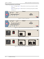
IPmux-1 Front Panel.............................................................................................................. 2-4
IPmux-1 Front Panel for Two Ethernet Ports .......................................................................... 2-4
IPmux-1 Rear Panel............................................................................................................... 2-4
IPmux-1 Rear Panel for Two Ethernet Ports ........................................................................... 2-4
IPmux-1E Front Panel............................................................................................................ 2-5
IPmux-1E Front Panel for Two Ethernet Ports ........................................................................ 2-5
IPmux-1E Rear Panel (FXS Option) ........................................................................................ 2-5
3-1. IPmux-1 Front Panel.............................................................................................................. 3-1
3-2. IPmux-1E Front Panel............................................................................................................ 3-2
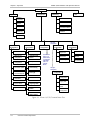
3-3. IPmux-1 (E1/T1) Terminal Menu Tree.................................................................................... 3-6
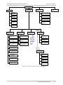
3-4. IPmux-1E ISDN-S Terminal Menu Tree ................................................................................. 3-7
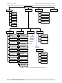
3-5. IPmux-1E FXS/FXO/E&M Terminal Menu Tree....................................................................... 3-8
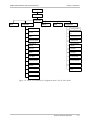
3-6. IPmux-1/1E Connection Configuration Menu Tree for Static Mode........................................ 3-9
3-7. IPmux-1E Connection Configuration Menu Tree for Dynamic CAS Mode............................ 3-10
3-8. IPmux-1E Connection Configuration Menu Tree for CESoIP Mode ...................................... 3-11
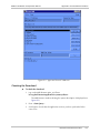
3-9. IPmux-1/1E Main Menu ...................................................................................................... 3-12
3-10. IPmux-1/1E System Menu ................................................................................................. 3-13
3-11. IPmux-1/1E Configuration Menu ....................................................................................... 3-13
3-12. IPmux-1E ISDN-S Configuration Menu .............................................................................. 3-14
3-13. IPmux-1E FXS/FXO/E&M Configuration Menu ................................................................... 3-14
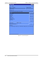
3-14. Performance Monitoring Menu for IPmux-1 ...................................................................... 3-15
3-15. Performance Monitoring Menu for IPmux-1E ISDN-S ........................................................ 3-15
3-16. Performance Monitoring Menu for IPmux-1E FXS/FXO/E&M ............................................. 3-16
IPmux-1/1E Installation and Operation Manual
iii
Table of Contents
4-1.
4-2.
4-3.
4-4.
4-5.
4-6.
4-7.
4-8.
iv
E1 Statistics............................................................................................................................ 4-6
LAN Statistics....................................................................................................................... 4-11
LAN Statistics....................................................................................................................... 4-14
Bundle Connection Status ................................................................................................... 4-17
IPmux-1 External Loop ........................................................................................................ 4-23
IPmux-1 Internal Loop......................................................................................................... 4-23
IPmux-1E/ISDN External Loop ............................................................................................. 4-24
IPmux-1E/ISDN Internal Loop ............................................................................................. 4-24
IPmux-1/1E Installation and Operation Manual
Table of Contents
List of Tables
1-1. Fiber Options ........................................................................................................................ 1-7
1-2. Ethernet Frame Structure..................................................................................................... 1-17
1-3. UDP Ports Definition........................................................................................................... 1-18
1-4. VLAN Check for Packets that are Received by IPmux-1/1E .................................................. 1-25
1-5. VLAN Check for Packets that are Sent by IPmux-1/1E.......................................................... 1-25
1-6. Switch Behavior .................................................................................................................. 1-27
1-7. Basic Mode ......................................................................................................................... 1-27
1-8. User Tagged Mode .............................................................................................................. 1-28
1-9. User Untagged Mode .......................................................................................................... 1-29
1-10. Rate Mode ........................................................................................................................ 1-30
1-11. Rate+User Tagged Mode .................................................................................................. 1-31
1-12. Rate+User Untagged Mode .............................................................................................. 1-32
2-1.
2-2.
2-3.
2-4.
2-5.
2-6.
2-7.
E1/T1 Port Connectors Pin Assignment .................................................................................. 2-5
Ethernet Port Pin Assignment................................................................................................. 2-6
Control Port Pin Assignment .................................................................................................. 2-6
ISDN-S-Interface Pin Assignments.......................................................................................... 2-6
FXS/FXO Interface Pin Assignment......................................................................................... 2-6
E&M Interface Pin Assignment............................................................................................... 2-7
External Clock Port Pin Assignment........................................................................................ 2-7
3-1.
3-2.
3-3.
3-4.
3-5.
3-6.
IPmux-1 LED Indicators......................................................................................................... 3-2
IPmux-1E (BRI/FXS/FXO/E&M) LED Indicators ....................................................................... 3-3
IPmux-1/1E Main Menu Options ......................................................................................... 3-12
IPmux-1/1E System Menu Options ...................................................................................... 3-12
Configuration Options ......................................................................................................... 3-14
Performance Monitoring Menu Options .............................................................................. 3-16
4-1.
4-2.
4-3.
4-4.
4-5.
4-6.
Event Types ........................................................................................................................... 4-2
IPmux-1 Troubleshooting Chart ............................................................................................. 4-4
E1/T1 Alarms ......................................................................................................................... 4-7
LAN Statistics Parameters..................................................................................................... 4-12
LAN Statistics Parameters..................................................................................................... 4-15
Bundle Connection Status Parameters ................................................................................. 4-17
IPmux-1/1E Installation and Operation Manual
v
Table of Contents
vi
IPmux-1/1E Installation and Operation Manual
Chapter 1
Introduction
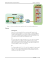
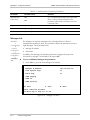
1.1 Overview
IPmux-1 and IPmux-1E (referred to as IPmux-1/1E) offer a solution for extending
traditional E1/T1, ISDN, or POTS TDM services transparently over Packet Switched
Networks (PSNs) such as IP, Ethernet, and MPLS networks. The device converts
the data stream coming from its user ports into configurable sized IP packets that
are extended over the Fast Ethernet network port, and vice versa. IPmux-1/1E
offers end-to-end synchronization for voice/leased line applications. IPmux-1/1E
also features a Fast Ethernet user port for data (Ethernet) connectivity to the
IP/Ethernet network. Management is performed locally by a terminal, or remotely
via Telnet or SNMP.
IPmux-1/1E offers:
•
E1/T1 service in IPMux-1 or E1/T1 with echo canceling in IPmux-1E
•
ISDN BRI (‘S’) extension in IPmux-1E
•
Analog extension (FXS, FXO, or E&M) with optional echo canceling in
IPmux-1E.
The IPmux family implements TDMoIP® technology to carry TDM transport
over IP. IPmux-1E ISDN BRI channels are transported as TDM timeslots, while the
analog FXS/FXO/E&M channels are digitized and carried as fractional E1/T1 with
CAS.
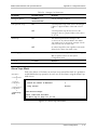
Versions
•
IPmux-1 with E1 interface
Balanced line with an RJ-45 (120Ω) connector
Unbalanced line with an RJ-45 (75Ω) connector (RJ-45 to BNC cable
adapter is supplied)
•
IPmux-1 with T1 interface – Balanced with an RJ-45 connector
•
IPmux-1E with ISDN BRI interface – 4 ISDN ‘S’ RJ-45 connectors
•
IPmux-1E with FXS Interface – 4 analog ‘FXS’ RJ-11 connectors, and optional
echo canceller
•
IPmux-1E with FXO interface – 4 analog ‘FXO’ RJ-11 connectors, and
optional echo canceller
•
IPmux-1E with E&M interface – 4 analog ‘E&M’ RJ-45 connectors, and
optional echo canceller
Overview
1-1
IPmux-1/1E Installation and Operation Manual
Chapter 1 Introduction
•
IPmux-1E with E1 interface and an echo canceller
Balanced line with an RJ-45 connector
Unbalanced line with a mini-coaxial connector (TBNC)
•
IPmux-1E with T1 interface and an echo canceller
Balanced line with an RJ-45 connector
Unbalanced line with a mini-coaxial connector (TBNC).
An external clock port and user Ethernet interface are optional for IPmux-1/1E.
Options
IPmux-1/1E is a 1U high, easy-to-install standalone unit. A rack mount installation
option is available: RM-25 for IPmux-1, and RM-26 for IPmux-1E.
IPmux-1 can be ordered with AC or DC power supply. IPmux-1E is only available
with AC power supply.
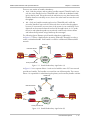
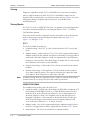
Applications
Typical IPmux-1/1E applications are shown with E1/T1, ISDN, and FXS/FXO/E&M
interfaces.
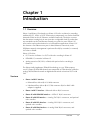
Figure 1-1 illustrates multiplexing voice and data over an Ethernet link.
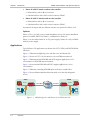
Figure 1-2 shows an E1/T1 circuit extension over an IP/Ethernet network.
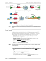
Figure 1-3 illustrates mixed ISDN BRI and POTS support application of V5.1
concentration of ISDN BRI remote terminals.
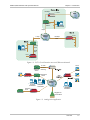
Figure 1-4 shows mixed ISDN BRI and POTS support application of voice
concentration.
Figure 1-5 illustrates extending ISDN BRI ports and LAN of a small office.
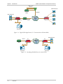
Figure 1-6 shows Ethernet-based multi-tenant with voice and data integrated
access.
SITE A
SITE B
E1/T1
PBX
10/100 Mbps
IPmux-1
IP/Ethernet
Network
E1/T1
10/100 Mbps
IPmux-1
Figure 1-1. Multiplexing Voice and Data over an IP/Ethernet Link
1-2
Overview
PBX
IPmux-1/1E Installation and Operation Manual
Chapter 1 Introduction
100 Mbps
n × E1/T1
PSTN
IPmux-8/16
Ethernet
Switch
1 Gbps
1 Gbps
IP/Ethernet
Network
E1/T1
100 Mbps
Fiber
IPmux-1
Ethernet
Switch
10/100
Mbps
E1/T1
IPmux-1
Figure 1-2. E1/T1 Circuit Extension over an IP/Ethernet Network
E1 CAS
Telephone
Switch
POTS
POTS
For FXS
Grooming
Fast Ethernet
Switch
IPmux-1E
IP/Ethernet
Network
Computer
Workstation
Computer
Workstation
Computer
Workstation
Fractional
E1/T1
IPmux-1
Megaplex as
Channel Bank
Figure 1-3. Analog Voice Application
Overview
1-3
IPmux-1/1E Installation and Operation Manual
Chapter 1 Introduction
ISDN U Ports
or V5.1
ISDN Telephones
Telephone
Switch
Megaplex
ISDN Telephones
Ethernet
Switch
IPmux-1E
IP/Ethernet
Network
IPmux-1E
Computer
Workstation
Figure 1-4. Digital ISDN Application (V5.1 Concentration of Remote BRIs)
ISDN Telephones
ISDN S
TE
NT
IP/Ethernet
Network
PBX
IPmux-1E
Computer
Workstation
IPmux-1E
Computer
Workstation
Figure 1-5. Extending ISDN BRI Ports of a Small Office
1-4
Overview
IPmux-1/1E Installation and Operation Manual
Chapter 1 Introduction
E1/T1
IPmux-1
FXS
IPmux-1E
BRI
BRI
Grooming
Internet
IPmux-1E
Megaplex
E1 CAS
Analog
Telephone Grooming
Switch
Switch
Ethernet
Switch
IP Network
Ethernet
Switch
Figure 1-6. Ethernet-based Multi-tenant Application with Voice and Data Integrated Access
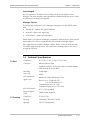
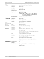
Features
Management
IPmux-1/1E can be managed locally by connecting an ASCII terminal to the
RS-232 port on the front panel, or via Telnet or SNMP. The SNMP management
capability enables fully graphical, user-friendly management using the RADview
Service Center TDMoIP® network management stations offered by RAD, as well
as management by other SNMP-based management systems.
T1
The T1 port and framers comply with ANSI T1.403, G.703, and G.704 standards.
T1 jitter performance is according to G.824 and TR-62411. The T1 framers
support unframed, SF, ESF and CAS framing. The T1 port supports long haul and
short haul input signals and can be monitored for alarms and error statistics. FDL
and transmit PRM for T1/ESF are also supported.
E1
The E1 port complies with G.703, G.704, and G.823 standards. E1 framers comply
with G.704. The E1 framers support unframed, framed, CRC4 MF and CAS MF
framing. The E1 port supports long haul and short haul input signals and can be
monitored for alarms and error statistics.
Overview
1-5
IPmux-1/1E Installation and Operation Manual
Chapter 1 Introduction
ISDN BRI
IPmux-1E has 4-ports, S-interface only. Each port can be configured as either NT
or TE (Network/User) by jumper and software; NT or TE is configured per device.
IPmux-1E can be configured to 1, 2, 3 or 4 active ports.
IPmux-1E works in transparent mode (no termination/compression of the BRI “D”
channels). It operates opposite a Megaplex unit, as a concentrator in transparent
mode, or opposite another IPmux-1E with ISDN BRI ports.
FXS/FXO/E&M
IPmux-1E has 4 FXS/FXO/E&M interface ports for POTS connection. An IPmux unit
with an E1/T1 CAS interface can groom FXS/FXO/E&M channels from the remote
sites. IPmux-1E analog options interwork with Megaplex analog and E1/T1
modules via the Megaplex TDMoIP® main link (ML-IP).
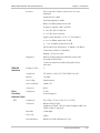
IP
The data stream coming from the E1 or T1 port is converted into IP packets that
are transported over the Fast Ethernet port, and vice versa.
TDM bytes are encapsulated in a UDP frame that runs over IP and over Ethernet.
The number of TDM bytes in an IP frame is configurable for throughput/delay
tradeoff.
Each device has a single IP address (Host IP). A configurable destination IP address
is assigned to the IP packets. IP ToS field support can be configured for IP Level
Priority. In Redundancy Mode, a secondary IP Address is used for the backup
bundle; this device IP Address defines a response for a ping, but not for
management.
Ethernet Ports
IPmux-1/1E is available with two Ethernet ports (user and network ports). The
optional user Ethernet port is used for user LAN connectivity/access, in addition to
the TDM service connectivity.
The Ethernet ports work in either transparent bridge mode or in a second mode
that enables user port rate limiting.
The Ethernet network port can be either UTP or fiber. The Ethernet user port is
UTP only.
Note
1-6
•
Fiber option – standard 100BaseFx full-duplex port (see Table 1-1).
•
UTP option – A standard 10/100BaseT half/full-duplex port with
auto-negotiation support. If auto-negotiation is disabled, Ethernet mode should
be configured.
Half-duplex operation in the IPmux-1/1E network port is not recommended,
because collisions and backoffs cause large delay variation and may exceed the
delay variation buffer tolerance at the receiving end, causing buffer underflows and
errors to occur.
Overview
IPmux-1/1E Installation and Operation Manual
Chapter 1 Introduction
Table 1-1. Fiber Options
Interface Type Wavelength
(nm)
Optical Power
(dBm)
Min
Max
Receive
Sensitivity
(dBm)
Optical
Budget
(dB)*
Loss
(dB/km)
Min
Max
SC multimode
1310
-20
-14
-31
8*
1
4
SC single mode
1310
-20
-14
-31
8*
0.5
0.8
LC multimode
1310
-19
-14
-32
10*
1
4
LC single mode
1310
-15
-8
-32
14*
0.5
0.8
*Permitted fiber optic cable length differs according to fiber characteristics, splices,
and connectors.
Note
When a user port option (only UTP) is chosen, the network fiber option is LC. If
there is no user port, the network fiber option is SC.
To calculate optical budget:
Optical Budget [dB] =
Receive Sensitivity–Optical Power–3 (Aging) – Connectors/Patch Panels Loss
To calculate distance:
Distance = Optical Budget/Maximum Loss
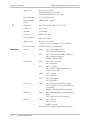
TDMoIP® Operation Modes
E1/T1 operation modes are:
• Unframed E1/T1 over UDP over IP over Ethernet
•
Fractional E1/T1 over UDP over IP over Ethernet
•
Fractional E1/T1 with CAS over UDP over IP over Ethernet.
ISDN BRI operation modes are:
• NT mode over UDP over IP over Ethernet
•
TE mode over UDP over IP over Ethernet.
IPmux-1E with FXS/FXO/E&M operates in fractional E1/T1 with CAS over UDP
over IP over Ethernet.
QoS
QoS supports:
•
Labeling IP level priority (ToS/Diffserv) for TDMoIP® packets
•
VLAN tagging and priority labeling according to IEEE 802.1p&Q for TDMoIP®
packets.
The user can configure the ToS (Type of Service) of the outgoing TDMoIP®
packets. This allows an en-route Layer 3 router or switch, which supports ToS, to
give higher priority to IPmux-1/1E TDMoIP® traffic for delay-sensitive and secure
applications. IPmux-1 allows you to configure the WHOLE ToS byte field, since
different vendors may use different bits to tag packets for traffic prioritization.
This also enables operation according to various RFC definitions (for example RFC
2474, RFC 791). The user can also configure VLAN priority bits for Level 2 priority.
Overview
1-7
IPmux-1/1E Installation and Operation Manual
Chapter 1 Introduction
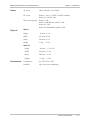
Timing
IPmux-1 maintains synchronization between TDM devices by deploying advanced
clock distribution mechanisms.
Available timing modes are:
Note
•
Loopback
•
Adaptive
•
Internal clock
•
External clock.
For more details, see Timing Modes below.
Bundle Redundancy
IPmux-1/1E features a bundle redundancy capability. This feature enables the user
to backup the TDMoIP® traffic in case of fault at the bundle connection level
and/or the TDM level. This feature permits the user to set a different path for the
primary bundle and for the secondary bundle (different IP networks, different
links, different IPmux units, etc) and thus rely on two routes, which are not
influenced by the same faulty IP/Ethernet conditions. The following redundancy
modes are supported:
•
1+1: Both the primary and secondary bundles transmit TDMoIP traffic, but
only the active bundle receives TDMoIP traffic, while the redundant bundle
ignores the Rx path.
•
1:1: Only one bundle transmits and receives TDMoIP traffic while the
secondary bundle is kept on hold.
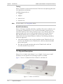
1.2 Physical Description
IPmux-1E is a 1U high 19-inch (IPmux-1 is a 1U high 8.5-inch), easy-to-install
standalone unit. An optional rack mounting kit option is available.
Figure 1-7 shows a 3-dimensional view of IPmux-1 and IPmux-1E.
Figure 1-7. IPmux-1/1E 3D View
1-8
Physical Description
IPmux-1/1E Installation and Operation Manual
Chapter 1 Introduction
The control interface and indicator LEDs are located on the front panel of
IPmux-1/1E. For further details, see Chapter 3.
User and network ports and power supply are located on the rear panel of
IPmux-1/1E. For further details, see Chapter 2.
1.3 Functional Description
IPmux-1/1E provides TDM connectivity across the IP/Ethernet network. A single
bundle (group of timeslots) can be transmitted to a predefined far-end bundle.
IPmux-1/1E supports ICMP (ping), and generates ARP in case of unknown next
hop MAC addresses, answers ARP requests, and supports 802.3 VLAN Ethernet
format.
IPmux-1/1E supports a variety of interfaces: E1/T1, ISDN BRI and analog POTs.
Traffic is transmitted over the network as E1/T1 or fractional E1/T1, using the
TDMoIP® method. IPmux-1/1E supports an Ethernet user port for user LAN
connectivity.
Configuration and management are provided via the IPmux-1/1E local terminal,
Telnet or RADview management tool (SNMP).
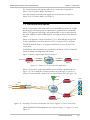
Figure 1-8 shows a typical application for IPmux-1.
10/100BaseT
E1/T1 Port
IPmux-1
100BaseFx
10/100BaseT
IP/Ethernet
Network
100BaseFx
E1/T1 Port
IPmux-1
Figure 1-8. IPmux-1 E1/T1 Point-to-Point Application
IPmux-1/1E works in conjunction with the rest of the IPmux product line (see
Figure 1-9). The combination of IPmux products provides up to 31 per E1 or
24 per T1 remote bundles, attached to one central IPmux-4/16 (see Figure 1-9).
E1/T1
Megaplex
E1/T1
Line 2
Line 4
POTs
E1/T1
IPmux-8/16
Line 1
Line 3
IPmux-8/16
IP over
Ethernet
E1/T1
IPmux-1E
E1/T1
IPmux-1
Figure 1-9. Grooming of Timeslots from Remote Sites into a Single E1/T1 Port at Central Site
Other ISDN/FXS/FXO/E&M applications are shown in Figure 1-3, Figure 1-4, and
Figure 1-5.
Functional Description
1-9
IPmux-1/1E Installation and Operation Manual
Chapter 1 Introduction
Operation Modes
Static Mode
When the timeslot allocation is static and no activity is detected, the payload can
be efficiently encoded using a constant bit rate.
The TDMoIP® payload consists of between one and thirty 48-octet subframes.
The number of subframes is pre-configured and typically chosen according to
latency and bandwidth constraints.
Dynamic CAS Mode
When timeslots are dynamically allocated, and CAS can be detected for
bandwidth conservation, the payload can be efficiently encoded using a variable
bit rate.
CESoIP Mode
In general, when the timeslot allocation is static and no activity is detected, the
payload can be efficiently encoded using a constant bit rate.
The CESoIP payload size is based on the packetization delay (in msec); the
minimum size is 1 msec, and increases in steps of 1 msec.
E1/T1
This section describes the IPmux-1 E1/T1 operation modes, which are:
•
Unframed – valid for static and CESoIP/E1
•
Fractional – valid only for static and CESoIP
•
Fractional with CAS –valid only for static and dynamic CAS .
Unframed (Transparent)
In the transparent mode, the incoming bit stream from each channel (regardless of
framing) is converted into IP over Ethernet frames. This option provides clear
channel end-to-end service (unframed).
Fractional
In the fractional mode, the incoming bit stream is regarded as a sequence of
N × 64 kbps channel groups (according to framing). Each predefined group of
channels is converted into a structure block. The structure block is packetized into
IP frames and transmitted.
This mode allows transmission of several selected timeslots without the whole E1
or T1 frame, as in transparent mode.
Note
1-10
Use Fractional mode when grooming ISDN BRI channels from a remote IPmux-1E
unit.
Functional Description
IPmux-1/1E Installation and Operation Manual
Chapter 1 Introduction
Fractional with CAS
In the fractional-with-CAS mode, the structure block (as described under
Fractional Operation Modes, above) also includes Channel Associated Signaling
(CAS). The relevant portion of the signaling channel is packetized and sent to the
destination.
Note
Use Fractional with CAS mode when grooming FXS/FXO/E&M channels from a
remote IPmux-1E unit.
ISDN BRI
The section describes the IPmux-1E ISDN BRI S-interface operation modes, which
are:
•
TE mode
•
NT mode.
The selected mode applies to all 4 channels. The NT or TE mode is determined by
phantom feeding and software setting, which is enabled/disabled by jumpers
located on the ISDN BRI card (see Chapter 2).
TE Mode
All four channels are configured in TE (Terminal Equipment) as defined in I.430.
NT Mode
All four channels are configured in NT (Network Termination) as defined in I.430.
TE Deactivation is not used in NT mode, and Layer 1 is always in active.
Note
If the jumpers enable phantom feeding, the TE mode cannot be selected as the
IPmux-1E operation mode. If phantom feeding is disabled, both NT and TE are valid
options.
FXS/FXO/E&M
The section describes the FXS/FXO/E&M operation modes, which are:
•
E1 mode
•
T1-D4 mode
•
T1 ESF mode.
The IPmux-1E FXS/FXO/E&M operation modes allow IPmux to work opposite E1,
T1-D4, or T1-ESF. Two parameters are set internally when choosing one of the
options:
•
A-Law/µ-Law
A-Law when E1 mode is selected
µ-Law is used in PCM CODEC when T1 (D4 or ESF) is selected.
•
E1, T1-D4, and T1-ESF with CAS are structured differently in the TDM ↔IP
interworking function. A different structure must be used when working
opposite each one.
Functional Description
1-11
IPmux-1/1E Installation and Operation Manual
Chapter 1 Introduction
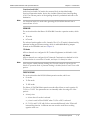
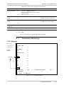
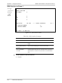
Timeslot Assignment in a Bundle
A bundle is a group of timeslots associated with a specific E1 or T1 channel.
IPmux-1/1E places individual or multiple TDM timeslots (up to 31 (E1) or 24 (T1)
timeslots) into bundles with a single IP address destination.
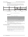
ISDN BRI
The timeslot assignment in a bundle for IPmux-1E with ISDN BRI (when working
opposite IPmux with E1/T1 or Megaplex) is as follows:
First Channel
B1
B2
Second Channel
D
MSB Bits 7, 6 contain
D channel information
B1
B2
D
…
MSB Bits 7, 6 contain
D channel information
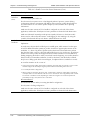
Figure 1-10. Timeslot Assignment in a Bundle, for IPmux-1E/ISDN
As shown in Figure 1-10, the four ISDN BRI channels consume 12 timeslots in the
bundle. The E1/T1 IPmux should work in framed mode (no CAS).
The three TS groups in the bundle are assigned according to ISDN BRI channel
numbers; the first group is assigned to the lowest ISDN BRI channel that is
enabled, etc.
FXS/FXO/E&M
The timeslot assignment in a bundle with analog (FXS/FXO/E&M) is straightforward.
Each timeslot in a bundle is assigned to a specific analog channel according to
analog channel numbers; the first timeslot is assigned to the lowest analog channel
that is configured, etc.
Note
The E1/T1 TDMoIP® gateway that works opposite the analog channels should work
in Framed with CAS mode.
Bundle Redundancy
IPmux-1/1E features a bundle redundancy capability. This feature enables the user
to backup the TDMoIP® traffic in case of fault at the bundle connection level
and/or the TDM level. This feature permits the user to set a different path for the
primary bundle and for the secondary bundle (different IP networks, different
links, different IPmux units, etc) and thus rely on two routs, which are not
influenced by the same faulty IP/Ethernet conditions.
The triggers for the bundle flip are user configurable in terms of number of events
and the time period in which the events will be counted. The user can configure
thresholds for both the TDM physical error levels and the Bundle connection error
level. The first threshold that will be breached will trigger a redundancy flip.
1-12
Functional Description
IPmux-1/1E Installation and Operation Manual
Chapter 1 Introduction
There are two modes of bundle redundancy:
• 1+1 – Both the primary and secondary bundles transmit TDMoIP® traffic, but
only the active bundle receives TDMoIP® traffic, while the redundant bundle
ignores the Rx path. This mode results in minimum recovery time between the
bundles whenever switch/flip occurs, but on the other hand increases the total
throughput.
•
1:1 – Only one bundle transmits and receives TDMoIP® traffic while the
secondary bundle is kept on hold. This mode does not affect the throughput,
however, it increases the recovery time of the system in case switch/flip occurs
(depends on the network elements involved in the application). In 1:1 mode,
the active and redundant paths are monitored continuously to detect failure
and initiate the flip/switch using OAM keep-alive messages.
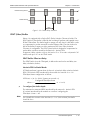
The following figures illustrate typical bundle redundancy applications.
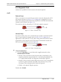
In Figure 1-11 IPmux-1 duplicates the incoming TDM traffic internally in order to
create a redundant bundle. Each bundle is routed to a different IP/Ethernet/MPLS
network.
Radio Link
Redundant Bundle
E1/T1
E1/T1
IPmux-1
PBX
Packet
Switched
Network
IPmux-1
PBX
Primary Active Bundle
Figure 1-11. Bundle Redundancy Application (A)
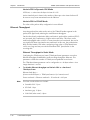
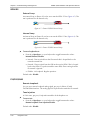
In Figure 1-12 two separate IPmux-1 units are fed with the same E1/T1 stream and
provide two bundles. The bundles are routed into two different paths. The remote
IPmux-1 is responsible for administering the primary and secondary bundle activities.
Satellite Link
Redundant Bundle
E1/T1
IPmux-1
PBX
E1/T1
IPmux-1
E1/T1
Packet
Switched
Network
IPmux-1
PBX
Primary Active Bundle
Figure 1-12. Bundle Redundancy Application (B)
Functional Description
1-13
IPmux-1/1E Installation and Operation Manual
Chapter 1 Introduction
Testing
Diagnostic capabilities include E1/T1 or ISDN BRI S local and remote loopback
tests for rapid localization of faults. The E1/T1 or ISDN BRI S channel can be
looped locally, toward the line, or toward the remote end (see Chapter 4 for more
information). Remote loopback and tone injection are available for the
FXS/FXO/E&M port.
Timing Modes
The E1/T1 Tx clock, or ISDN/FXS PCM clock, can operate in several timing modes
to provide maximum flexibility for connecting the IPmux-1/1E E1, T1, ISDN or
FXS/FXO/E&M channels.
Each of the clocks must be configured correctly on both the receive and transmit
ends to ensure proper operation and prevent pattern slips (see Figure 1-13,
Figure 1-15, and Figure 1-16).
E1/T1
The E1/T1 available Tx modes are:
Note
•
Loopback timing – the E1/T1 Tx clock is derived from the E1/T1 receive (Rx)
clock.
•
Adaptive timing – in this mode, the E1 or T1 Tx clock is regenerated using the
Adaptive method. In this method, the fill level of the buffer receiving packets is
monitored. If the buffer begins to overfill, the regenerated Tx clock frequency
increases to avoid overflow. If the buffer begins to empty, the Tx clock (toward
the TDM device) decreases to avoid underflow.
•
Internal clock timing – in this mode, the Tx clock is received from an internal
oscillator.
•
External clock timing – in this mode the Tx clock is taken from the external
clock input (Ordering option). The external clock port also outputs the input
clock signal to allow connection to other units, if needed.
In adaptive timing mode the regenerated clock is subject to network Packet Delay
Variation and may not comply with jitter and wander specifications.
ISDN/FXS/FXO/E&M
The available timing modes for the PCM clock are:
• Loopback timing – available only when IPmux-1E ISDN BRI is configured as TE
(not available in ISDN BRI NT mode or for FXS/FXO/E&M interface). In this
mode the PCM clock is derived from Channel 1. It is recommended not to
deactivate Channel 1 while it is in loopback clock so that data will not be
damaged. If Channel 1 is disconnected or deactivated (by the NT side), the
PCM clock will change to Internal clock and a momentary disruption will
occur to the other channels (2, 3, 4), if they are active.
1-14
•
Adaptive mode – the clock is regenerated using the Adaptive method, where
the rate of arriving packets is used to regenerate the clock (see E1/T1, above).
•
Internal Mode – the clock is received from an internal oscillator.
Functional Description
IPmux-1/1E Installation and Operation Manual
Chapter 1 Introduction
Network Timing Schemes
The following paragraphs describe typical timing schemes and the correct timing
mode settings for achieving end-to-end synchronization.
External Network Timing
When the edges of the network are synchronized by an external network clock
source, all the IPmux-1 units should be configured to work in loopback timing
mode (see Figure 1-13). This topology enables any-to-any connectivity.
Clock from External Distribution Network
E1/T1
E1/T1
E1/T1 Device
E1/T1
E1/T1
IPmux-1
IPmux-1
LBT Mode E1/T1 Device
IP/Ethernet
LBT Mode
E1/T1
IPmux-1
E1/T1 Device
IPmux-1
LBT Mode
E1/T1
LBT Mode E1/T1 Device
Figure 1-13. IPmux-1 in Loopback Timing Mode
External timing from the network can also be issued to IPmux-1 by External Clock
input; in this case, the E1/T1 device will use the LBT mode.
Clock from External Distribution Network
E1/T1 Device
E1/T1 Device
E1/T1
IP/Ethernet
IPmux-1
LBT Mode
External
Clock Mode
IPmux-1
E1/T1
External
Clock Mode
LBT Mode
Figure 1-14. IPmux-1 in External Clock Mode
Single Source Clock Network
When a common clock is not available on all the ends of the network one of the
IPmux-1 devices is configured to work in Loopback timing mode, while the other
IPmux-1 device is configured to work in Adaptive timing mode (see Figure 1-15).
Functional Description
1-15
IPmux-1/1E Installation and Operation Manual
Chapter 1 Introduction
Loopback
Timing Mode
E1/T1 Device
E1/T1 Device
E1/T1
E1/T1
Master Clock
Source Device
Adaptive Mode
IP/Ethernet
E1/T1
IPmux-1
IPmux-1
E1/T1
Remote Loopback
Timing Device
Figure 1-15. IPmux-1 in Adaptive Timing Mode
Adaptive
ISDN
IPmux-1E
LBT
Adaptive
IP over
Ethernet
ISDN
E1
Megaplex
IPmux-8/16
IPmux-1E
ISDN
Grooming
of BRI LBT
V5.1
Grooming of FXS
in E1 CAS
Telephone
Switch
Adaptive
POTS
IPmux-1E
Figure 1-16. IPmux-1E in Adaptive Timing Mode
Note
Megaplex can also be connected directly to the network, via its TDMoIP® main link
(ML-IP).
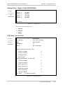
Frame Format
The Ethernet frame sent by the IPmux-1 is a UDP datagram that transfers E1/T1
payload bytes over IP over Ethernet (UDP payload + UDP header + IP header +
Ethernet header). The UDP payload size depends on the connection mode:
•
Static mode: The UDP payload size is equal to TDM bytes per frame
(TDM bytes/frame configuration).
•
Dynamic CAS mode: The maximum UDP payload size depends on the
number of configured time slots and is equal to:
[(TSA + 4) x (number of configured timeslots)] + 4]
where TSA = Active timeslot bytes in frame
Note
Active timeslot bytes in frame are the number of bytes per timeslot that are passed
per Ethernet frame.
An Active timeslot is one where a call is detected by monitoring CAS.
The UDP payload size is not fixed–it depends on the number of active time
slots:
[(TSA + 4) x (number of active timeslots)] + 4]
•
CESoIP mode: The UDP payload size is equal to:
[(Configured Packet Delay) x (number of configured timeslots) x 8] + 12
1-16
Functional Description
IPmux-1/1E Installation and Operation Manual
Chapter 1 Introduction
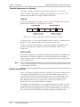
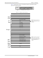
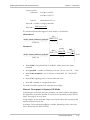
Table 1-2 specifies the structure of the different headers, special fields, and the
payload in the Ethernet packet.
MAC
IP
UDP
Payload
Figure 1-17. TDMoIP® Frame Structure
Table 1-2. Ethernet Frame Structure
MAC
Layer
LLC
Layer
IP Layer
UDP
Layer
Data
Layer
MAC
Layer
Field length (bytes)
Field
7
Preamble
1
SFD
6
Destination MAC Address
6
Source MAC Address
2
Type
1
Vers/HLEN
1
Service Type
2
Total Length
2
Identification
1
Flags/Fragment Offset (most)
1
Fragment Offset (least)
1
Time to Live
1
Protocol
2
Header Checksum
4
Source IP Address
4
Destination IP Address
2
UDP Source Port
2
UDP Destination Port
2
UDP Message Length
2
UDP Checksum
...
Payload
4
CRC
Note: IEEE 802.1p&q VLAN
Tagging (additional 4 bytes if
enabled)
Note: The UDP source port
field is used to transfer the
destination bundle number in
static and dynamic CAS
modes.
Functional Description
1-17
IPmux-1/1E Installation and Operation Manual
Chapter 1 Introduction
VLAN Support
VLAN, according to IEEE 802.1p&Q, adds four bytes to the MAC layer of the
Ethernet frame. The user can set the contents of these bytes, MAC layer priority
and VLAN ID. In this mode, only VLAN format frames are sent and received by
IPmux-1. Figure 1-18 shows the VLAN tag format.
00
8
802.1D Tag Protocol Type
6
VID
CFI = 0
user_priority
81
5
4
1
Priority
8
1
VLAN ID
Figure 1-18. VLAN Tag Format (802.1p&Q)
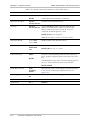
UDP Support
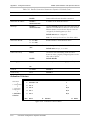
Table 1-3. UDP Ports Definition
Field Length (Bits)
Field Description
Value
Function
2 bytes
UDP Source Port
2–497d*
Destination timeslots bundle
2 bytes
UDP Destination Port
2142d
Standard TDMoIP® UDP
port
* The MSB of this field can be either 1 or 0 for inband end-to-end proprietary signaling.
Note
The UDP Source Port field is used for destination timeslots bundle indication.
For example, if the destination is:
Bundle 1 – 02, Bundle 2 – 03, Bundle 3 – 04, Bundle 4 – 05, etc.
For more information about VLAN tagging, refer to IEEE 802.1p&Q.
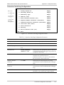
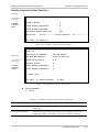
Packet Delay Variation
Packets are transmitted at set intervals. Packet Delay Variation is the maximum
deviation from the nominal time the packets are expected to arrive at the far end
device. IPmux-1 has a buffer that compensates for the deviation from the expected
packet arrival time to prevent IPmux-1 buffers from emptying out or overflowing.
Packet Delay Variation is an important network parameter. Large PDV (exceeding
the jitter buffer configuration) will cause receive buffer underflows and errors at
the TDM level (see Figure 1-19).
To compensate for large PDV, configure the PDVT (jitter) buffer to a higher value.
1-18
Functional Description
IPmux-1/1E Installation and Operation Manual
Chapter 1 Introduction
Packets Leaving IPmux-1
t
Packets Arriving
t
PDV
Figure 1-19. Packet Delay Variation
PDVT (Jitter) Buffer
IPmux-1 is equipped with a Packet DVT (Delay Variation Tolerance) buffer. The
PDVT buffer or jitter buffer is filled by the incoming IP packets and emptied out to
fill the TDM stream. The buffer begins to empty out only after it is half full in order
to compensate for packet starvation from the Ethernet side. The time it takes for
half of the buffer to empty out is the maximum DVT time. Delay Variation
Tolerance is configurable. The PDVT (jitter) buffer is designed to compensate for
packet delay variation caused by the network + intrinsic PDV.
It supports a delay variation of up to 300 ms for E1 or T1 in static or dynamic CAS
modes, and up to 127 ms in CESoIP mode.
PDVT Buffer Effect on Delay
The PDVT buffer is on the TDM path; it adds to the total end-to-end delay (see
delay calculation, below).
Intrinsic PDV in Static Mode
If TDM bytes/frame is greater than 48, there is an intrinsic delay variation (intrinsic
PDV). The intrinsic PDV introduced by the module is a function of n>1 in
TDM bytes/frame configuration as follows:
I.PDV (ms) = [(n-1) x 1000) / (frames per second × n]
where n =
Configured TDM bytes/frame
48
(n = 1 to 8).
To configure jitter buffer depth:
The estimated or measured PDV introduced by the network + intrinsic PDV
(if it exists) introduced by the module as a result of configuring the
TDM bytes / frame > 48.
Note
For a bundle that contains a few timeslots (i.e. 1 to 3) the minimal jitter buffer
should be 6 ms.
Functional Description
1-19
Chapter 1 Introduction
IPmux-1/1E Installation and Operation Manual
Intrinsic PDV in Dynamic CAS Mode
I.PDV (ms) = active time slot bytes in frame X 0.125
Active timeslot bytes in frame is the number of bytes per active time slot that will
be sent on every frame transmitted over the Ethernet.
Intrinsic PDV in CESoIP Mode
The value of the packet delay configuration is user-defined.
Ethernet Throughput
Increasing payload size reduces the ratio of the TDMoIP header segment in the
packet, thus significantly reducing the total Ethernet throughput.
On the other hand, packetization delay and intrinsic packet delay variation (PDVT)
are increased; this contributes to a higher end-to-end delay. This effect can be
small and negligible when a full E1 (or many timeslots) are transferred, but can be
very significant when few timeslots are transferred. In this case, the packetization
delay and the intrinsic PDV when configuring a large value of TDM bytes/frame
can be very large and may exceed the maximum PDVT (jitter) buffer on the
receiving end.
Ethernet Throughput in Static Mode
Configuring the TDM bytes per frame (TDM bytes/frame) parameter can reduce
Ethernet throughput (bandwidth or traffic traveling through the Ethernet). This
parameter controls the number of TDM bytes encapsulated in one frame.
The TDM bytes/frame parameter can be configured to n x 48 bytes where n is an
integer between 1 and 30.
To calculate Ethernet throughput and intrinsic PDV as a function of
TDM bytes/frame:
Ethernet load (bps) =
[(frame overhead (bytes) + TDM bytes/frame) x 8] x frames/second
Frame overhead = Ethernet overhead + IP overhead = 46 bytes
Note
The frame overhead does not include:
• Preamble field: 7 bytes
• SFD field: 1 byte
• Interframe gap: 12 bytes
• VLAN field (when used): 4 bytes.
1-20
Functional Description
IPmux-1/1E Installation and Operation Manual
Frame/second =
Unframed:
Chapter 1 Introduction
5447/n for a full E1
4107/n for a full T1
Framed:
8000 x k/(46.875 x n)
Where k = number of assigned timeslots
Where n =
TDM bytes/frame
48
The maximum Ethernet throughput in static mode is calculated by:
Unstructured
data
64
748
8000 * TS
( VLAN + frame overhead + payload) *
* 8 bits
1444444
424444444
3
47 * n
frame size
Structured
pointer
CAS
748
64748 64
data
64
748 8000 * TS
TS
8000 * TS +
+ 500 *
(47 * 8) - 1
2 * 8 bits
( VLAN + frame overhead + payload) *
1444444
424444444
3
47 * n
frame size
•
where VLAN is an optional field: if enabled it adds 4 bytes to the frame
overhead
•
where payload = number of TDM bytes in frame, (48, 96, 144, 192, … 384)
•
where frame overhead = size of 46 bytes, include MAC, LLC, IP and UDP
layer
•
where CAS is signaling (note: for structured mode only)
•
where TS is number of configured time slots.
The result in both the equations is in bits per second [bps].
Ethernet Throughput in Dynamic CAS Mode
Configuring the active time slot bytes parameter can reduce Ethernet throughput.
This parameter controls the number of TCM bytes encapsulated per time slot in a
frame. The range is 24 to 64 bytes.
A large number of time slots and a large active time slot bytes size can surpass the
maximum Ethernet frame size.
In dynamic CAS mode the throughput is variable, depending on the active time
slots as defined by the ABCD CAS bits.
Functional Description
1-21
IPmux-1/1E Installation and Operation Manual
Chapter 1 Introduction
The maximum Ethernet throughput in dynamic CAS mode is calculated by:
[(
Note
8000
payload
) x ((payload+ 4) x TS) + 4 + frame overhead] x 8 bits
•
where frame overhead is 46 bytes, including MAC, LLC, IP, and UFP layers
•
where TS = number of configured time slots
•
where payload = number of active time slot bytes per frame (24 to 64)
The frame overhead does not include:
• Preamble field: 7 bytes
• SFD field: 1 byte
• Interframe gap: 12 bytes
• VLAN field (when used): 4 bytes.
Ethernet Throughput in CESoIP Mode
Configuring the packet delay and the number of time slots controls the Ethernet
throughput. The range of the packet delay is 3 to 127 msec.
A large number of time slots and a long packet delay can surpass the maximum
Ethernet frame size.
The maximum Ethernet throughput in CESoIP mode is calculated by:
[(
1000
packet delay
) x ((
packet delay
8
) x TS) + 12 + frame overhead] x 8 bits
•
where frame overhead is 46 bytes, including MAC, LLC, IP, and UFP layers
•
where TS = number of configured time slots:
for an unframed E1 interface = 32
for an unframed E1 interface = 24
•
where packet delay = 3 to 127.
Round Trip Delay
The voice path round-trip delay is a function of all connections and network
parameters. The calculation for E1/T1 in each connection mode is described in the
following sections.
1-22
Functional Description
IPmux-1/1E Installation and Operation Manual
Chapter 1 Introduction
Round Trip Delay in Static Mode
(±2 µs) RTDelay(µs) = 2 x [
47x n
x 125 µs + PDVT buffer µs +1000 µs] + network round trip delay
NTS
TDM bytes/frame
•
where n =
•
where NTS = number of timeslots assigned; in unframed mode NTS is
constant: 32 for E1, 24 for T1
48
Round Trip Delay in Dynamic CAS Mode
RTDelay(µs) = 2 x [
•
8000000
payload
+ PDVT buffer µs +1000 µs] + network round trip delay
where payload = number of active time slot bytes per frame (24 to 64)
Packet Delay in CESoIP Mode
RTDelay(µs) = 2 x [packet delay+ PDVT buffer (µs) +1000 µs] + network round trip delay
•
where packet delay is a configuration parameter
Reorder and Duplication of Ethernet Frames
IPmux-1/1E handles situations in the IP network where:
•
Packets are reordered by the network
•
Packets are duplicated.
Static Mode
Reordering Frames
The ability to correct problems of reordering is only supported for odd values of
payload, i.e. 1, 3, 5, 7, …, 29.
You can reorder up to seven frames; the number depends on the number of
TDM bytes/frame size and buffer size.
The number of frames that can be reordered is calculated by:
( jitterbuffer[m sec] − 1)(Tsx8)
47 xpayload
Note
•
where Ts = number of timeslots
•
where payload = number of TDM bytes in frame, i.e. 1, 3, 5, 7, …, 29.
The maximum number of frames that can be reordered is seven, even if your
calculation>7.
Functional Description
1-23
IPmux-1/1E Installation and Operation Manual
Chapter 1 Introduction
Duplicated Frames
When frames are duplicated, IPmux-1/1E only uses the later frame.
Dynamic CAS Mode
Reordering and duplication of frames is not supported; the frames pass to the
TDM side without any modification.
CESoIP Mode
The number of frames that are reordered depends on the frame delay and the
jitter buffer size.
The number of frames that can be reordered is calculated by:
jitterbuffersize[m sec[
framedelay[m sec]
OAM Connectivity
When a destination IPmux is lost, the traffic load that is transmitted to that IPmux
is significantly decreased (several packets per second per connection). The IPmux
starts transmitting at full rate only when it detects an IPmux at the remote side.
OAM Connectivity is used to detect a valid connection (the remote IPmux will
confirm it recognizes the connection and that it is enabled). It prevents flooding by
a handshake.
The control packets are run over a unique bundle number that is used for this
purpose. The control packets have the same VLAN ID and TOS of the originating
connection. The control packet uses the TDMoIP® UDP number.
OAM connectivity can be enabled or disabled.
Note
For control packets, the UDP check sum is not calculated nor checked.
End-to-End Alarm Generation
An end-to-end alarm generation mechanism exists in IPmux-1 to facilitate the
following alarms:
•
Unframed – AIS is transmitted toward the near-end PBX in event of:
Far-end LOS, AIS
PDVT underflow/overflow.
•
Framed – Timeslot/CAS configurable alarm pattern is transmitted toward the
near-end PBX in event of:
Far-end LOS, LOF, AIS
PDVT underflow/overflow.
1-24
Functional Description
IPmux-1/1E Installation and Operation Manual
Chapter 1 Introduction
VLAN Traffic Behavior
Table 1-4 lists the IP and VLAN validity checks that are performed with each
Ethernet packet that is received by IPmux1/1E.
Table 1-4. VLAN Check for Packets that are Received by IPmux-1/1E
Packet Type
Source IP Check
VLAN Check
Management
Performed
Performed
TDM over IP
Performed
Performed
Receiving Ping
Not performed
ARP
Not performed
Not performed, even if it
is one of the IPs that is
configured for the
manager or for the
connection
Telnet
Performed only when
Telnet access mark is from
manager
Performed only when
Telnet access mark is from
manager
Table 1-5 lists the IP and VLAN validity checks that are performed with each
Ethernet packet that is sent by IPmux1/1E.
Table 1-5. VLAN Check for Packets that are Sent by IPmux-1/1E
Packet Type
VLAN Support
Management
As configured for the manager
TDM over IP
As configured for the connection
Answer to Ping
If the IPmux-1/1E received the packet with VLAN tagging: the
IPmux-1/1E replies with the same VLAN ID (even if it’s one of
IPs that is configured for the manager or for the connection)
If the IPmux-1/1E received the packet without VLAN tagging: if
it’s one of the IPs that is configured for the manager or for the
connection, the IPmux-1/1E replies with the VLAN ID that is in
the manager or connection configuration
ARP initiated by us
Telnet
No VLAN value unless it is to one of the managers or the
connection’s IP address
Ping initiated by us
Functional Description
1-25
IPmux-1/1E Installation and Operation Manual
Chapter 1 Introduction
Ethernet User Port
The Ethernet user port allows a user to aggregate both TDMoIP® traffic and his
private network LAN traffic to a single Ethernet network connection without
requiring an access switch. This is a cost effective solution for MTU or small office
applications. A rate limiter to restrict user port traffic is supported.
IPmux-1/1E contains an internal switch where one of its ports is connected to a
TDMoIP® interworking function, another external switch port is used as the user
port, and the third is used as an Ethernet network port.
Ethernet
User Port
E1 Port
Internal
Switch
Ethernet
Network Port
TDMoIP
Figure 1-20. IPmux-1/1E with Ethernet User Port
Note
Priority is always given to TDMoIP® packets inside the internal switch.
Internal Switch Operation Modes
IPmux-1/1E offers a user LAN port in addition to the LAN port on the network
side. The device performs switching at level 2. The switch supports both
transparent bridging and VLAN-aware bridging. The switch supports rate limiting of
traffic going from the user port to the network port. It supports up to 12K MAC
addresses (depending on their values and the order in which they are learned).
The switch modes are described later in this section. They are:
•
Basic mode
•
User Tagged mode
•
User Untagged mode
•
Rate mode
•
Rate + User Tagged mode.
•
Rate + User Untagged mode.
Rate Limiter Option
In this option a rate limiter is available to limit user port traffic. This feature is
valuable when a limited bandwidth DSL modem, for example, is used to extend
the Ethernet link (generally when the Ethernet link rate is limited/shaped to a lower
rate after IPmux). In this case TDMoIP® packets will be dropped in the modem
even if it was prioritized at the IPmux internal switch. This is prevented by limiting
the user port to actual link rate minus TDMoIP® bandwidth. The rate limiter can
limit user traffic at 50 kbps steps up to 5 Mbps and in 1 Mbps steps from 5 Mbps
to 100 Mbps.
Note
1-26
Access to the IPmux host for management is possible only from the network port.
Functional Description
IPmux-1/1E Installation and Operation Manual
Chapter 1 Introduction
Switch Behavior
Use Table 1-6 to determine the operation mode.
Table 1-6. Switch Behavior
Network VLAN
Tagging
User VLAN
Tagging
Disable
Rate Limit
Rate Limit>0
Rate Limit=0 (Disable)
Disable
Rate Mode (see Table 1-10)
Basic Mode (see Table 1-7)
Enable
Disable
Rate+User Untagged Mode
(see Table 1-12)
User Untagged Mode (see Table 1-9)
Enable
Enable
Rate+User Tagged Mode
(see Table 1-11)
User Tagged Mode (see Table 1-8)
Basic Mode
Features:
•
Network port learning is based on MAC
•
User port learning is based on MAC
•
TDMoIP® & Managers traffic is tagged or untagged.
Table 1-7. Basic Mode
Notes
Frame Action
Switch Action
A tagged frame enters the Network port
Switched to User port without changing
the frame*
A tagged frame enters the User port
Switched to Network port without
changing the frame*
An untagged frame enters the Network
port**
Switched to User port without changing
the frame*
An untagged frame enters the User port**
Switched to Network port without
changing the frame*
*
The switch may decide not to pass the frame to the other port, based on its
learning.
** A priority-tagged frame (frame with a tag and VLAN-ID 0) is treated just like an
untagged frame. This includes rewriting the priority field with 0.
Functional Description
1-27
IPmux-1/1E Installation and Operation Manual
Chapter 1 Introduction
User Tagged Mode
Features:
•
Network port learning is based on MAC+VLAN
•
User port learning is based on MAC+VLAN
•
TDMoIP® & manager traffic must be tagged.
Table 1-8. User Tagged Mode
Frame Action
Switch Action
A tagged frame enters the network port
Both user and network ports are members of
frame’s VLAN
Switched to user port without changing the frame*
Either the user or network port is not a
member of frame’s VLAN
Discarded
A tagged frame enters the user port
Both user and network port are members of
frame’s VLAN
Switched to network port without changing the
frame*
Either the user or network port is not a
member of frame’s VLAN
Discarded
An untagged frame enters the network port (see
Note 2)
Both user and network ports are members of
the network port default VLAN
Switched to user port*
Either the user or network port is not a
member of the network port default VLAN
Discarded
Default network port VLAN ID is added with
priority 0
An untagged frame enters the user port**
Both user and network ports are members of
the user port default VLAN
Switched to network port*
Either the user or network port is not a
member of the User port default VLAN
Discarded
Notes
*
Default user port VLAN ID is added with
priority 0
The switch may decide not to pass the frame to the other port, based on its
learning.
** A priority-tagged frame (frame with a tag and VLAN-ID 0) is treated just like an
untagged frame. This includes rewriting the priority field with 0.
1-28
Functional Description
IPmux-1/1E Installation and Operation Manual
Chapter 1 Introduction
User Untagged Mode
Features:
•
Network port learning is based on MAC+VLAN
•
User port learning is based on MAC+VLAN
•
TDMoIP® & manager traffic must be tagged.
Table 1-9. User Untagged Mode
Frame Action
Switch Action
A tagged frame enters the network port
Both user and network ports are members of
frame’s VLAN
Switched to user port*, and the tag is removed
Either the user or network port is not a
member of frame’s VLAN
Discarded
A tagged frame enters the user port
Both user and network port are members of
frame’s VLAN
Switched to network port without changing the
frame*
Either the user or network port is not a
member of frame’s VLAN
Discarded
An untagged frame enters the network port (see
Note 2)
Both user and network ports are members of
the network port default VLAN
Switched to user port without changing the frame*
Either the user or network port is not a
member of the network port default VLAN
Discarded
An untagged frame enters the user port**
Both user and network ports are members of
the user port default VLAN
Switched to network port*
Either the user or network port is not a
member of the user port default VLAN
Discarded
Notes
*
Default user port VLAN ID is added with
priority 0
The switch may decide not to pass the frame to the other port, based on its
learning.
** A priority-tagged frame (frame with a tag and VLAN-ID 0) is treated just like an
untagged frame. This includes rewriting the priority field with 0.
Functional Description
1-29
IPmux-1/1E Installation and Operation Manual
Chapter 1 Introduction
Rate Mode
Features:
•
There is no network port learning
•
User port learning is based on MAC
•
TDMoIP® & manager traffic are tagged or untagged.
Table 1-10. Rate Mode
Frame Action
Switch Action
A tagged frame enters the network port
Switched to user port without changing the
frame***
A tagged frame enters the user port
Switched to network port without changing the
frame*
Subject to rate limiting
An untagged frame enters the network port
Switched to user port without changing the
frame***
An untagged frame enters the user port
Switched to network port without changing the
frame*
Subject to rate limiting
Note
*
The switch may decide not to pass the frame to the other port, based on its
learning.
** A priority-tagged frame (frame with a tag and VLAN-ID 0) is treated just like an
untagged frame. This includes rewriting the priority field with 0.
** Learning is disabled; therefore, every frame is switched. The network port is
typically connected to another switch.
1-30
Functional Description
IPmux-1/1E Installation and Operation Manual
Chapter 1 Introduction
Rate + User Tagged Mode
Features:
•
No network port learning
•
User port learning is based on MAC
•
TDMoIP® & manager traffic must be tagged.
Table 1-11. Rate+User Tagged Mode
Frame Action
Switch Action
A tagged frame enters the network port
Switched to user port without changing the
frame***
A tagged frame enters the user port
Both user and network ports are members of
frames’s VLAN
Switched to network port without changing the
frame*
Subject to rate limiting
Either the user or network port is not a
member of frames’s VLAN
Discarded
An untagged frame enters the network port
Switched to user port without changing the
frame***
An untagged frame enters the user port**
Discarded
Note
*
The switch may decide not to pass the frame to the other port, based on its
learning.
** A priority-tagged frame (frame with a tag and VLAN-ID 0) is treated just like an
untagged frame. This includes rewriting the priority field with 0.
*** Learning is disabled; therefore, every frame is switched. The network port is
typically connected to another switch.
Functional Description
1-31
IPmux-1/1E Installation and Operation Manual
Chapter 1 Introduction
Rate + User Untagged Mode
Features:
•
Network port learning is based on MAC + VLAN number
•
User port learning is based on MAC + VLAN number
•
TDMoIP® & manager traffic must be tagged.
Table 1-12. Rate+User Untagged Mode
Frame Action
Switch Action
A tagged frame enters the network port
Both user and network ports members of
frame’s VLAN
Switched to user port*, and tag is removed
Either the user or network port is not a
member of frames’s VLAN
Discarded
A tagged frame enters the user port
Discarded
An untagged frame enters the network port (see
Note 2)
Both user and network ports are members of
port Network port default VLAN
Switched to user port without changing (see
Note 1)
Either user or network port is not a member of
the network port default VLAN
Discarded
A untagged frame enters the user port**
Both user and network ports members of
User port default VLAN
Switched to network port*
Subject to rate limiting
Default user port VLAN ID is added with priority 0
Either user or network port not member of
User port default VLAN
Notes
*
Discarded
The switch may decide not to pass the frame to the other port, based on its
learning.
** A priority-tagged frame (frame with a tag and VLAN-ID 0) is treated just like an
untagged frame. This includes rewriting the priority field with 0.
DHCP
Dynamic Host Configuration Protocol (DHCP) is a TCP/IP protocol that enables
PCs and workstations to get temporary or permanent IP Addresses (out of a pool)
from centrally administered servers. DHCP is based on RFC 1531 and RFC 1533.
1-32
Functional Description
IPmux-1/1E Installation and Operation Manual
Chapter 1 Introduction
Lease Length
You can request an IP Address for an infinite period of time (Infinite Lease);
however, you must accept the time period that is determined by the server, even if
it is different from what you requested.
Manager Option
The server may send IPmux-1/1E a Manager configuration via the DHCP option
field:
•
Manager IP – Option 200 (type IP Address)
•
VLAN ID – Option 201 (type long)
•
VLAN Priority – Option 202 (type byte).
When IPmux-1/1E requests a Manager configuration from the server, there may be
many replies. The device accepts the offer that includes a Manager Option.
If the reply does not include a Manager Option, IPmux-1/1E waits three seconds
for another reply from the server. If no replies have Manager Option, the device
accepts the first offer.
1.4 Technical Specifications
E1 Port
E1 Framing
Compliance
ITU-T Rec. G.703, G.706, G.732, G.823
Connector
Balanced: RJ-45 8-pin
Unbalanced: RJ-45 75Ω (comes with an external adapter
cable from RJ-45 to two BNC)
Data Rate
2.048 Mbps
Line Code
HDB3
Line Impedance
Balanced: 120Ω; Unbalanced: 75Ω
Signal Levels
Receive: 0 to -32 dB with LTU
0 to -10 dB without LTU
Transmit Balanced: ±3V ±10%
Transmit Unbalanced: ±2.37V ±10%
Jitter Performance
ITU-T G.823 standard
External Adapter
Cable
TBNC to BNC required
Compliance
G.704, G.706
Framing
Unframed, CRC4 MF, CAS MF
Signaling
CAS, CCS (transparent)
Technical Specifications
1-33
IPmux-1/1E Installation and Operation Manual
Chapter 1 Introduction
T1 Port
T1 Framing
Local
Terminal and
Control
Interface
Ethernet
Compliance
ANSI T1.403, ITU-T Rec. G.703, G.704
Connector
RJ-45, 8-pin
Data Rate
1.544 Mbps
Line Code
B8ZS, B7ZS, AMI
Line Impedance
100Ω, balanced
Signal Levels
Receive: 0 to -30 dB
Transmit: 0 dB, -7.5 dB, -15 dB, -22.5 dB, with CSU
±2.7V ±10%, adjustable, measured in range
0 to 655 feet, without CSU
Jitter Performance
AT&T TR-62411, G.824 standards
Compliance
ANSI T1.403
Framing
Passthrough, SF, ESF
Signaling
CAS (bit robbing), CCS (transparent)
DB-9, female
Mode
RS-232/V.24 (DCE)
Baud Rate
9.6, 19.2, 38.4, 57.6, 115.2 kbps
Connector
DB-9
Compliance
IEEE 802.3, 802.3u, Ethernet, 802.1p&Q
Connector
UTP: RJ-45, 8-pin
Fiber: SC (without user port), LC (network port when with
optional user port is present)
Ports
1 or 2 (if optional user port is used)
Data Rate
UTP: 10 Mbps or 100 Mbps, full or half-duplex
Fiber: 100 Mbps full-duplex
Range
Up to 100m on UTP Category 5 cables
For optical interfaces: see optical budget calculation
(Table 1-1)
Analog Voice
Number of Voice
Channels
4
Modulation Method
PCM (per ITU-T G.711 and AT&T PUB-43801)
µ-Law or A-Law
1-34
Technical Specifications
IPmux-1/1E Installation and Operation Manual
Interfaces
Chapter 1 Introduction
FXS: Loop start for direct connection to a 2-wire
telephone
Nominal level: 0 dBm
Nominal impedance: 600Ω
Return loss (ERL): Better than 20 dB
Frequency response: (Ref: 1020 Hz)
• ±0.5 dB, 300 TO 3000 Hz
• ±1.1 dB, 250 to 3400 Hz
Signal to total distortion, G.712, G.713 method 2:
• 0 to -30 dBm0, better than 33 dB
• +3 to -45 dBm0, better than 22 dB
Idle channel noise: Better than -70 dBm0 (+20 dBrnc)
Transformer isolation: 1500 VRMS
Ringing - 22 Hz, sine wave
Diagnostics
Remote analog loopback towards the remote side,
activated from local side
1 kHz tone injection towards analog side activity
indicators
ISDN S0
Interface
Echo
Canceller
Number of Ports
4
Compliance
ETS 300012, I.430, NTT, 5ESS, DMS-100, NI1
Bit Rate
192 kbps
Line Coding
Pseudo-ternary
Line Termination
100Ω ± 5%
Connector
RJ-45
Compliance
G.168
8 ms tail support
Compliance
ITUa-T Rec. G.703, G.706, G.732, G.823
Connector
Balanced: RJ-45 8-pin
Unbalanced: TBNC 75Ω (an external adapter cable from
TBNC to BNC is required)
Data Rate
2.048 Mbps
Line Code
HDB3
Line Impedance
Balanced: 120Ω; Unbalanced: 75Ω
External Clock
E1
Technical Specifications
1-35
IPmux-1/1E Installation and Operation Manual
Chapter 1 Introduction
T1
Indicators
Signal Levels
Receive: 0 to -10 dB
Transmit balanced: ±3V ±10%
Transmit unbalanced: ±2.37V ±10%
Jitter Performance
ITU-T G.823 standard
External Adapter
Cable
TBNC to BNC required
Compliance
ANSI T1.403, ITU-T Rec. G.703, G.704
Connector
RJ-45, 8-pin
Data Rate
1.544 Mbps
Line Code
B8ZS, B7ZS, AMI
Line Impedance
Balanced: 100Ω
Signal Levels
Receive: 0 to -10 dB
Transmit: ±2.75V ±10% at 0 to 655 ft with DSU
Jitter Performance
AT&T TR-62411, G.824 standards
General
PWR
ON – power supply is OK
OFF – malfunction detected
RDY
ON – self-test is successfully completed
OFF – self-test in progress
BLINKS – self-test failure
LINK
OFF – line is not active
ON – line is OK
ACT
OFF – no activity
ON – a frame is being transmitted or
received on the line
100M
OFF – 10 MHz
ON – 100 MHz
FDX
OFF – half-duplex
ON – full-duplex
E1/T1 Port
SYNC
ON – port is synchronized (no alarm)
OFF – signal loss, LOF or AIS is detected
(local alarm)
BLINKS – RDI detected (remote alarm)
ISDN Port
SYNC
ON – ISDN BRI frame is synchronized (no
alarm)
OFF – signal loss, LOF is detected
FXS Port
SYNC
ON – off-hook
OFF – on-hook
BLINKS – ringing
Ethernet Port
Note: All LEDs are green and ON after power-up.
1-36
Technical Specifications
IPmux-1/1E Installation and Operation Manual
Power
Physical
Chapter 1 Introduction
AC Source
100 to 240 VAC, 50 or 60 Hz
DC Source
IPmux-1: -36 to -72 VDC (-48 VDC nominal)
IPmux-1E: -48 VDC only
Power Consumption
IPmux-1: 4W
IPmux-1 (with Ethernet switch): 10W
IPmux-1E: 25W
IPmux-1E (with Ethernet switch): 32W
IPmux-1
Height
43 mm / 1.7 in
Width
215 mm / 8.4 in
Depth
246 mm / 9.7 in
Weight
1.2 kg
/ 2.7 lb
IPmux-1E
Height
Environment
44 mm / 1.7 in (1U)
Width
432 mm / 17.0 in
Depth
246 mm / 9.5 in
Weight
2.3 kg / 5.1 lb
Temperature
0 to 50°C/32 to 122°F
Humidity
Up to 90%, non-condensing
Technical Specifications
1-37
Chapter 1 Introduction
1-38
Technical Specifications
IPmux-1/1E Installation and Operation Manual
Chapter 2
Installation
IPmux-1/1E is delivered completely assembled for bench-top installation. The only
mechanical installation procedures that may be necessary are optional installation
in a 19-inch rack. For rack installation instructions, refer to the guide that comes
with the RM kit.
After installing the unit, configure IPmux-1/1E using an ASCII terminal connected
to the IPmux-1/1E control port, or Telnet or RADview TDMoIP® management
application. The IPmux-1/1E configuration procedures are described in Chapter 3
and Appendix E of this manual. Configuration parameters are explained in
Appendix E.
If problems are encountered, refer to Chapter 4 for test and diagnostics
instructions.
Warning
No internal settings, adjustment, maintenance and repairs may be performed
by either the operator or the user; such activities may be performed only by
skilled service personnel who are aware of the hazards involved.
Always observe standard safety precautions during installation, operation, and
maintenance of this product.
2.1 Site Requirements and Prerequisites
Install AC-powered IPmux-1/1E units within 1.5m (5 feet) of an easily-accessible
grounded AC outlet capable of furnishing the required supply voltage, in the range
of 100 to 240 VAC.
DC-powered IPmux-1/1E units require a -48 VDC power source. The positive pole
can be earthed.
The maximum permissible current capability of the branch distribution circuit that
supplies power to the product is 16A.
Caution
The DC power source must be isolated from the mains supply by double or
reinforced insulation. A suitable fuse or a circuit breaker (16A) should be
integrated in the negative power-supply line.
Allow at least 90 cm (36 inches) of frontal clearance for operator access. Allow at
least 10 cm (4 inches) clearance at the rear of the unit for cable connections. Make
sure that the ventilation holes are not blocked.
The ambient operating temperature of IPmux-1/1E is 0 to 50o C (32 to 122o F), at a
relative humidity of up to 90%, non-condensing.
Site Requirements and Prerequisites
2-1
IPmux-1/1E Installation and Operation Manual
Chapter 2 Installation
2.2 Package Contents
The IPmux-1/1E package contains the following items:
•
IPmux-1/1E unit
•
Technical documentation CD
•
AC power cord or DC power supply connector kit
•
Kit containing hardware for mounting the unit in a 19-inch rack:
RM-35 for IPmux-1 (ordering option)
RM-34 for IPmux-1E (supplied with the unit).
2.3 Installation and Setup
Setting Internal Jumpers
IPmux-1
IPmux-1 internal jumpers and switches do not need to be configured by the user.
Therefore, removing the product cover is not required.
IPmux-1E
The IPmux-1E FXS/FXO/E&M version needs NO user internal jumper
configuration.
The IPmux-1E ISDN version contains jumpers that must be set for phantom feed
(see Figure 2-1). Open the case and verify the positions of internal jumpers before
proceeding to the IPmux-1E installation, which is explained below.
To open the IPmux-1E case:
1. Disconnect all the cables connected to IPmux-1E.
2. Release all cover screws at the top and side panels.
3. Remove the IPmux-1E top cover by pulling it back.
To set the IPmux-1E ISDN-S module jumpers:
If necessary, change the settings in accordance with the specific requirements of
your application:
•
ENA – enable phantom feed
•
DIS – disable phantom feed.
The phantom feed ENA/DIS setting influences the IPmux-1E ISDN BRI operation
mode. When phantom feed is disabled, the S-interface can be configured (through
software) to the TE or NT mode. When phantom feed is enabled, only the NT
mode is possible.
2-2
Installation and Setup
IPmux-1/1E Installation and Operation Manual
Chapter 2 Installation
Only qualified and authorized service personnel should have access to the
inside of the unit.
Warning
Disconnect the unit from the power line and from all the cables before
removing the cover.
Line voltages are present inside IPmux-1/ 1E when it is connected to power.
Moreover, under certain external fault conditions, dangerous voltages may
appear on the lines connected to IPmux-1/1E.
Any adjustment, maintenance, and repair of the opened device under voltage
should be avoided as much as possible and, when inevitable, should be
carried out only by a skilled technician who is aware of the hazards involved.
Capacitors inside the device may still be charged even after it has been
disconnected from its source of power.
Caution The IPmux-1/1E contains components sensitive to electrostatic discharge (ESD). To
DIS
ENA
prevent ESD damage, avoid touching the internal components, and before moving
jumpers, touch the IPmux-1/1E rear panel.
Figure 2-1. IPmux-1E ISDN-S Jumpers
To reinstall the top cover:
1. Position the IPmux-1/1E case on a flat, clean surface.
2. Slide the cover into the slots from the rear panel, and set the cover in place.
3. Fasten the cover with the 14 screws.
Installation and Setup
2-3
IPmux-1/1E Installation and Operation Manual
Chapter 2 Installation
Connecting Interfaces and Cables
Figure 2-2 through Figure 2-5 illustrate the front and rear panel options available
for IPmux-1.
Figure 2-6 through Figure 2-8 illustrate the rear and front panel options available
for IPmux-1E.
IPmux-1
PWR
RDY
SYNC
CONTROL
ETH
DCE
LINK
ACT
100M
FDX
®
Figure 2-2. IPmux-1 Front Panel
PWR
RDY
IPmux-1
SYNC
CONTROL
ETH1
DCE
ETH2
®
LINK
ACT
100M
FDX
Figure 2-3. IPmux-1 Front Panel for Two Ethernet Ports
POWER
CAUTION : FOR CONTINUED
PROTECTION AGAINST RISK OF
FIRE, REPLACE ONLY WITH SAME
TYPE AND RATING OF FUSE.
E1
ETH
Figure 2-4. IPmux-1 Rear Panel
POWER
CAUTION : FOR CONTINUED
PROTECTION AGAINST RISK OF
FIRE, REPLACE ONLY WITH SAME
TYPE AND RATING OF FUSE.
E1
USER
Figure 2-5. IPmux-1 Rear Panel for Two Ethernet Ports
2-4
Installation and Setup
NETWORK
IPmux-1/1E Installation and Operation Manual
PWR
IPmux-1E
RDY
ETH
LINK
Chapter 2 Installation
ACT
100M
CH1
CH3
FDX
CONTROL
CH2
CH4
DCE
®
SYNC
Figure 2-6. IPmux-1E Front Panel
PWR
IPmux-1E
RDY
ETH1
ETH2
CH1
CONTROL
CH2
CH3
DCE
CH4
®
LINK
ACT
100M
FDX
SYNC
Figure 2-7. IPmux-1E Front Panel for Two Ethernet Ports
POWER
CAUTION : FOR CONTINUED
PROTECTION AGAINST RISK OF
FIRE, REPLACE ONLY WITH SAME
TYPE AND RATING OF FUSE.
FXS
1
2
3
ETH
4
Figure 2-8. IPmux-1E Rear Panel (FXS Option)
Location of Connectors
Interface connections are made from the IPmux-1/1E back panel, as shown in
Figure 2-2.
• Table 2-1 lists the E1/T1 port pin assignment
•
Table 2-2 lists the Ethernet port pin assignment
•
Table 2-3 lists the control port pin assignment
•
Table 2-4 lists the ISDN-S connector pin assignment.
•
Table 2-5 lists the FXS/FXO connector pin assignment
•
Table 2-6 lists the E&M connector pin assignment
•
Table 2-7 lists the external clock port pin assignment.
Table 2-1. E1/T1 Port Connectors Pin Assignment
Pin
Designation
Direction
Function
1
RD (R)
Input
Receive data (ring)
2
RD (T)
Input
Receive data (tip)
3, 6
–
–
FGND
4
TD (R)
Output
Transmit data (ring)
5
TD (T)
Output
Transmit data (tip)
7, 8
–
N/A
Not connected
Installation and Setup
2-5
IPmux-1/1E Installation and Operation Manual
Chapter 2 Installation
Table 2-2. Ethernet Port Pin Assignment
Pin
Function
1
Tx+
2
Tx–
3
Rx+
4
–
5
–
6
Rx–
7
–
8
–
Table 2-3. Control Port Pin Assignment
Pin
Function
1
–
2
Rx
3
Tx
4
–
5
GND
6
–
7
–
8
–
9
–
Table 2-4. ISDN-S-Interface Pin Assignments
Pin
Function
3
Tx+
4
Rx+
5
Rx–
6
Tx–
Table 2-5. FXS/FXO Interface Pin Assignment
Pin
Designation
Direction
1, 2
Not connected
3
RING
IN/OUT
Two-wire input/output
4
TIP
IN/OUT
Two-wire input/output
5, 6
2-6
Function
Installation and Setup
Not connected
IPmux-1/1E Installation and Operation Manual
Chapter 2 Installation
Table 2-6. E&M Interface Pin Assignment
Pin
Designation
Function
1
SB
Signaling battery
2
M
M lead input
3
R1-0UT
4-wire voice output
2-wire voice input/output
4
R-IN
4-wire voice input
5
T-IN
4-wire voice input
6
T1-OUT
4-wire voice output
2-wire voice input/output
7
SC
Function depends on signalling mode:
• RS-464 Type I, III: Direct connection to signal ground
• RS-464 Type V, SSDCS: Connection to signal ground
through 1.1 kΩ resistor
• RS-464 Type II: SG lead
8
E
E lead output
Table 2-7. External Clock Port Pin Assignment
Pin
Signal Name
Function
1
RRING
Rx
2
RTIP
Rx
3
GND
Usually not connected
4
TRING
Tx
5
TTIP
Tx
6
GND
Usually not connected
7
–
Not connected
8
–
Not connected
Connecting the Power
To connect power to IPmux-1/1E, refer to the appropriate section below,
depending on your version of the unit (AC or DC).
Grounding
Interrupting the protective grounding conductor (inside or outside the instrument)
or disconnecting the protective earth terminal can make this instrument
dangerous. Intentional interruption is prohibited.
Warning
Before switching ON this instrument and before connecting any other cable,
the protective earth terminals of this instrument must be connected to the
protective ground conductor of the power cord.
Installation and Setup
2-7
IPmux-1/1E Installation and Operation Manual
Chapter 2 Installation
Fuses
Make sure that only fuses with the required rated current and specified type, as
marked on the IPmux-1/1E rear panel, are used for replacement: 1.6A T 250V.
Whenever it is likely that the protection offered by fuses has been impaired, the
instrument must be made inoperative and secured to prevent any operation.
Connecting the AC Power
AC power is supplied to IPmux-1/1E through the 1.5m (5 ft) standard power cable
terminated by a standard 3-prong plug. The cable is supplied with the unit.
To connect AC power:
1. Verify that the AC outlet is grounded properly. Ensure that the supply voltage is
in the range 100 VAC to 240 VAC.
2. Check that the POWER switch on the rear panel is set to OFF.
3. Connect the power cable to the rear panel connector first and then to the
AC mains outlet.
Connecting the DC Power
To connect DC power:
•
Warning
2-8
Refer to the DC power supply connection supplement.
Due to the high current capability of DC mains systems, care should be taken
when connecting the DC supply, in order to avoid short-circuits and fire
hazards.
DC units should be installed in a restricted access area, i.e., an area where
access is authorized only to qualified service and maintenance personnel.
Make sure that the DC supply is electrically isolated from any AC source, and
that the installation complies with the local codes.
The maximum permissible current capability of the branch distribution circuit
that supplies power to the product is 16A.
Before connecting the DC input plug, ensure that power is removed from the
DC circuit. Locate the circuit breaker of the panel board that services the
equipment, and switch it to the OFF position. When connecting the other end
of the DC cable, first connect the ground wire, then the position pole, and
lastly the negative pole. Switch the circuit breaker back to the ON position.
A readily accessible disconnect device that is suitably rated and approved
should be incorporated in the building installation.
Installation and Setup
Chapter 3
Operation
This chapter:
•
Provides a detailed description of the front panel controls and indicators and
their functions
•
Explains power-on and power-off procedures
•
Provides instructions for using a terminal connected to the IPmux-1/1E control
port
•
Describes how to navigate menus
•
Illustrates the following menus:
Main menu
Configuration menu
Viewing system information
Monitoring IPmux-1/1E performance.
For a detailed explanation of parameters on the menus, see Appendix E.
3.1
Front Panel Controls, Connectors, and Indicators
The IPmux-1/1E LEDs (see Figure 3-1 and Figure 3-2) are located on the left side of
the front panel. Table 3-1 and Table 3-2 list the functions of the IPmux-1 and
IPmux-1E system indicators and switches
IPmux-1
PWR
RDY
SYNC
CONTROL
ETH
DCE
LINK
ACT
100M
FDX
®
Figure 3-1. IPmux-1 Front Panel
Front Panel Controls, Connectors, and Indicators
3-1
IPmux-1/1E Installation and Operation Manual
Chapter 3 Operation
Table 3-1. IPmux-1 LED Indicators
Name
Function
PWR
ON – Unit is powered on
OFF – Unit is powered off
RDY
ON – Unit is operating properly
OFF – Self-test is in progress
Blinking – Malfunction is detected
SYNC
ON – TDM port is synchronized (no alarm)
OFF (unframed) – Signal loss or AIS detected
OFF (framed) – Signal loss, loss of frame or AIS
detected
Blinking – RDI is detected (remote alarm)
ETH LINK
ON – Link is OK
OFF – Link is not active
ETH ACT
ON – Frame is being transferred on link
OFF – No activity is detected on the link
ETH 100M
ON – 100 Mbps
OFF – 10 Mbps
ETH FDX
On: Full-duplex
Off: Half-duplex
PWR
IPmux-1E
RDY
ETH
LINK
ACT
100M
FDX
CH1
CH2
CH3
CH4
CONTROL
DCE
®
SYNC
Figure 3-2. IPmux-1E Front Panel
3-2
Front Panel Controls, Connectors, and Indicators
IPmux-1/1E Installation and Operation Manual
Chapter 3 Operation
Table 3-2. IPmux-1E (BRI/FXS/FXO/E&M) LED Indicators
Name
Function
PWR
ON – Unit is powered on
OFF – Unit is powered off
RDY
ON – Unit is operating properly
OFF – Self-test is in progress
Blinking – Malfunction is detected
SYNC
CH1–CH4
ISDN
ON – ISDN port is synchronized
OFF – LOF is detected
FXS/FXO/E&M
ON – OFF hook
OFF – ON hook
Blinking – Ringing
ETH LINK
ON – Link is OK
OFF – Link is not active
ETH ACT
ON – Frame is being transferred on link
OFF – No activity is detected on the link
ETH
100M
ON – 100 Mbps
ETH FDX
On: Full-duplex
OFF – 10 Mbps
Off: Half-duplex
3.2 Operating Instructions
Turning IPmux-1/1E On
Without Control Terminal
The IPmux-1/1E power switch is located on the rear panel.
To power up IPmux-1/1E without a control terminal:
1. Set the power supply switch, located on the rear panel, to ON.
2. Check the unit LED indicators, located on the left side of the front panel, and
the module indicators for proper operation (see Figure 3-1, Figure 3-2,
Table 3-1 and Table 3-2).
Operating Instructions
3-3
IPmux-1/1E Installation and Operation Manual
Chapter 3 Operation
With Control Terminal
To power up IPmux-1/1E with a control terminal:
1. Make sure all IPmux-1/1E cables and connectors are properly connected.
2. Connect IPmux-1/1E to a PC equipped with an ASCII terminal-emulation
application.
3. Turn on the control-terminal PC and set its default port parameters to
19,200 baud, 8 bits/character, 1 stop bit, no parity. Set the terminal emulator
to ANSI VT100 emulation (for optimal view of system menus).
4. Set the POWER switch, located on the rear panel, to ON.
5. When the initialization and self-test are over, a menu appears displaying
initialization and self-test results. If the self-test is successful, the RDY LED
(Figure 3-1 and Figure 3-2) on the left side of the front panel lights up. If
problems are encountered, refer to Chapter 4 for instructions.
6. Press <Esc> to open the configuration software.
7. Enter your User Name according to your assigned system privileges (either
Supervisor (su) or User and then your Password when prompted (the
factory-set password is xxxxxxxxxx).
The Main menu is displayed (Figure 3-9).
Note
If the password is invalid in three consecutive attempts, the system becomes
inaccessible for 15 minutes.
Login
User Name and Password
To enter as a superuser:
1. Enter su for User Name.
2. Enter xxxxxxxxxx for Password.
This allows you to configure all the parameters of IPmux-1/1E, and to change the
su and user passwords.
To view the unit’s configuration:
1. Enter user for User Name.
2. Enter xxxxxxxxxx for Password.
This does not allow you to make configuration changes.
To set all passwords to the default value (xxxxxxxxxx):
•
Note
Delete the unit’s configuration through the Configuration screens.
Deleting the unit’s configuration using <Ctrl+A> and choosing 4 in the Boot
menu does not set the password to the default value.
Turning IPmux-1/1E Off
To power off the unit:
•
3-4
Set the rear panel POWER switch to OFF.
Operating Instructions
IPmux-1/1E Installation and Operation Manual
Chapter 3 Operation
3.3 Getting Started
After installation, there are no special operating procedures for IPmux-1/1E. Once
it is powered up, the unit operates automatically.
If required, IPmux-1/1E can be reconfigured. Both the IPmux-1/1E configuration
and monitoring operations are performed locally from an ASCII terminal
connected to the control port. Detailed configuration procedures are given in
Overview of Menu Operations and Appendix E.
The following functions are supported (see menu trees in Figure 3-3, Figure 3-4,
Figure 3-5, Figure 3-6, Figure 3-7, and Figure 3-8):
•
Viewing system information
•
Modifying configuration and mode of operation, including setting system
default values
•
Viewing statistics and status.
3.4 Overview of Menu Operations
Navigating
Navigate the IPmux-1/1E terminal menus to set and view configuration
parameters:
•
Figure 3-3 maps the IPmux-1 terminal menus except for the Connection
Configuration menu.
•
Figure 3-4 maps the IPmux-1E ISDN-S terminal menus except for the
Connection Configuration menu.
•
Figure 3-5 maps the IPmux-1E FXS/FXO/E&M terminal menus except for the
Connection Configuration menu.
•
Figure 3-6 maps the IPmux-1E Connection Configuration menu for Static
Mode.
•
Figure 3-7 maps the IPmux-1E Connection Configuration menu for Dynamic
CAS Mode.
•
Figure 3-8 maps the IPmux-1E Connection Configuration menu for CESoIP
Mode.
Use these menu trees as a reference aid while performing configuration and
control functions. Appendix E illustrates menus, explains parameters, and lists
default values. Refer to Appendix E to find specific parameters.
Overview of Menu Operations
3-5
IPmux-1/1E Installation and Operation Manual
Chapter 3 Operation
Main Menu
2. Configuration
1. System
3.Performance
Monitoring
4. Exit
1.General
Information
1. E1/T1 Statistics
2.Self-Test
Results
2.LAN Status
3. Reset
3. Bundle
Connection Status
4.Event Log
4.Bundle Connection
Statistics
5. Ping
One-port
LAN Option
1. General
Configuration
2. E1/T1
Configuration
1. Host IP
1. Channel Status
2. Management
Configuration
2. Transmit Clock
Source
3. ASCII Terminal
Configuration
3. Loopback State
4.Time/Date Update
4. Rx Sensitivity
5. Software
Download/Upload
5. Line Type
6. Set Default
Parameters
6. Idle Code
7.System Name
7. Signaling Mode
3.Connection
Configuration
4.LAN
Configuration
Continued in
Figures 3-8
(Static Mode),
3-9 (Dynamic
CAS Mode),
and 3-10
(CESoIP
Mode)
1. Auto
Negotiation
1.Bundle ID
2. Max Capability
Advertised
2.Time Slot
Number
3. Default Type
3.Time Slot
Current Status
Two-port
LAN Option
4. Switch
Configuration
1. LAN
Configuration
2. Aging Time
8.System Location
8. Cond. Data
Pattern
3. Erase MAC
Table
4. VLAN
Configuration
9.Cond. CAS
(ABCD) Pattern
Figure 3-3. IPmux-1 (E1/T1) Terminal Menu Tree
3-6
Overview of Menu Operations
5.DS0 Bundle
Configuration
IPmux-1/1E Installation and Operation Manual
Chapter 3 Operation
Main Menu
2. Configuration
1. System
3.Performance
Monitoring
1.General
Information
ISDN Statistics
2.Self-Test
Results
2.LAN Status
3. Reset
3. Bundle
Connection Status
4.Event Log
4.Bundle Connection
Statistics
4. Exit
5. Ping
1. General
Configuration
2. ISDN
Configuration
1. Host IP
1. Interfaces Mode
2. Management
Configuration
2. Transmit Clock
Source
3. ASCII Terminal
Configuration
3. Channel
Configuration
4.Time/Date Update
5. Software
Download/Upload
6. Set Default
Parameters
3.Connection
Configuration
One-port
LAN Option
4.LAN
Configuration
1. Auto
Negotiation
Continued in
Figures 3-8
(Static Mode),
3-9 (Dynamic
CAS Mode),
and 3-10
(CESoIP
Mode)
2. Max Capability
Advertised
3. Default Type
Two-port
LAN Option
4. Switch
Configuration
1. LAN
Configuration
2. Aging Time
7.System Name
3. Erase MAC
Table
8.System Location
4. VLAN
Configuration
Figure 3-4. IPmux-1E ISDN-S Terminal Menu Tree
Overview of Menu Operations
3-7
IPmux-1/1E Installation and Operation Manual
Chapter 3 Operation
Main Menu
2. Configuration
1. System
3.Performance
Monitoring
1.General
Information
1. Analog Status
2.Self-Test
Results
2.LAN Status
3. Reset
3. Bundle
Connection Status
4.Event Log
4.Bundle Connection
Statistics
5. Ping
One-port
LAN Option
1. General
Configuration
2. Analog
Configuration
1. Host IP
1. Clock Source
2. Management
Configuration
2. Far End Type
3. ASCII Terminal
Configuration
3. Channel
Configuration
4.Time/Date Update
4. Signaling Profile
Configuration
5. Software
Download/Upload
5. Line Type
6. Set Default
Parameters
6. Idle Code
7.System Name
7. Signaling Mode
3.Connection
Configuration
4.LAN
Configuration
1. Auto
Negotiation
Continued in
Figures 3-8
(Static Mode),
3-9 (Dynamic
CAS Mode),
and 3-10
(CESoIP
Mode)
2. Max Capability
Advertised
3. Default Type
Two-port
LAN Option
4. Switch
Configuration
1. LAN
Configuration
2. Aging Time
8.System Location
8. Cond. Data
Pattern
3. Erase MAC
Table
4. VLAN
Configuration
9.Cond. CAS
(ABCD) Pattern
Figure 3-5. IPmux-1E FXS/FXO/E&M Terminal Menu Tree
3-8
Overview of Menu Operations
4. Exit
IPmux-1/1E Installation and Operation Manual
Chapter 3 Operation
Main Menu
2.Configuration
3.Connection
Configuration
1.Connection
Mode
2. Bundle Connection
Configuration
3. Secondary IP
Address
4. Secondary IP
Mask
5. Protection Switching
Configuration
1. Bundle ID
1. Primary Bundle ID
2. IP TOS
2. Secondary Bundle
ID
3. TDM Bytes in a
Frame
3. Redundancy Type
4. Connection Status
4. TDM Fail Time
5. Destination IP
Address
5. Event Threshold
Window
6. Next Hop
6. Sequence Number
Threshold
7. Destination
Bundle
7.Underflow/Overflow
Threshold
8. Jitter Buffer
8. Local Fail Time
9. OAM Connectivity
9. Force Connection
A. Redundancy
Function
A. Recovery
B. VLAN Tagging
B. Wait-To-Restore
Time
C. VLAN ID
E. VLAN Priority
Figure 3-6. IPmux-1/1E Connection Configuration Menu Tree for Static Mode
Overview of Menu Operations
3-9
IPmux-1/1E Installation and Operation Manual
Chapter 3 Operation
Main Menu
2.Configuration
3.Connection
Configuration
1.Connection
Mode
2. Bundle Connection
Configuration
3. Activation Criterion
1. Bundle ID
1. Pattern ID
2. IP TOS
2. Tx A
3. Active Time Slot
Bytes in Frame
3. Tx B
4. Connection Status
4. Tx C
5. Destination IP
Address
5. Tx D
6. Next Hop
7. Destination
Bundle
8. Jitter Buffer
9. OAM Connectivity
A. Redundancy
Function
B. VLAN Tagging
C. VLAN ID
E. VLAN Priority
Figure 3-7. IPmux-1E Connection Configuration Menu Tree for Dynamic CAS Mode
3-10
Overview of Menu Operations
IPmux-1/1E Installation and Operation Manual
Chapter 3 Operation
Main Menu
2.Configuration
3.Connection
Configuration
1.Connection
Mode
2. Bundle Connection
Configuration
1. Bundle ID
2. IP TOS
3. Packet Delay
4. Connection Status
5. Destination IP
Address
6. Next Hop
7. Source UDP
8. Destination UDP
9. Jitter Buffer
B. VLAN Tagging
C. VLAN ID
E. VLAN Priority
Figure 3-8. IPmux-1E Connection Configuration Menu Tree for CESoIP Mode
Main Menu
Figure 3-9 shows the IPmux-1/1E Main Menu. Access all system configuration and
control functions via this menu.
The Main menu options are described in Table 3-3.
At any point and from any screen, you can press <Esc> repeatedly, backing up
until you reach the main menu.
You exit the program only from this menu. In order to prevent unauthorized
access, it is recommended that when you finish a session, you return to the Main
Menu and type 4 to exit the program. A password is then required for reentry.
Overview of Menu Operations
3-11
IPmux-1/1E Installation and Operation Manual
Chapter 3 Operation
Table 3-3. IPmux-1/1E Main Menu Options
Option
Description
1. System
View and modify system parameters
2. Configuration
Define system configuration
3. Performance Monitoring
Monitor system performance
4. Exit
Exit the control software
MAIN MENU
1.System
2.Configuration
3.Performance Monitoring
4.Exit
>
>
>
Select item from the menu:
_
Use keys <1> to <4>
Figure 3-9. IPmux-1/1E Main Menu
System Menu
To access the System menu:
•
Type 1 (System) in the Main Menu.
From the System menu (see Figure 3-10) you can view and configure the options
described in Table 3-4. These options are explained in full detail in Appendix E.
Table 3-4. IPmux-1/1E System Menu Options
3-12
Option
Description
1. General Information
View IPmux-1/1E general information
2. Self-Test Results
Review self-test results obtained during system
power-up.
3. Reset
Reset IPmux-1/1E
4. Event Log
View a list of IPmux-1/1E events
5. Ping
Ping other network devices
Overview of Menu Operations
IPmux-1/1E Installation and Operation Manual
Chapter 3 Operation
SYSTEM
1. General Information
2. Self-Test Results
3. Reset
4. Event Log
>
5. Ping
ESC.
Exit
Select item from the menu.
Figure 3-10. IPmux-1/1E System Menu
Setting IPmux-1/1E Configuration Options
To access the Configuration menu:
•
Type 2 (Configuration) in the Main Menu.
The IPmux-1E E1/T1 Configuration menu is shown in Figure 3-3 and
Figure 3-11.
The IPmux-1E ISDN-S Configuration menu is shown in Figure 3-4 and
Figure 3-12.
The IPmux-1E FXS/FXO/E&M Configuration menu is shown in
Figure 3-5and Figure 3-13.
Table 3-5 describes the configuration options.
CONFIGURATION
1. General Configuration
2. E1/T1 Configuration
3. Connection Configuration
4. Switch Configuration
5. DS0 Bundle Configuration
ESC. Exit
Select item from the menu:
_
Figure 3-11. IPmux-1/1E Configuration Menu
Overview of Menu Operations
3-13
IPmux-1/1E Installation and Operation Manual
Chapter 3 Operation
CONFIGURATION
1. General Configuration
2. ISDN Configuration
3. Connection Configuration
4. LAN Configuration
ESC. Exit
Select item from the menu:
_
Figure 3-12. IPmux-1E ISDN-S Configuration Menu
CONFIGURATION
1. General Configuration
2. Analog Configuration
3. Connection Configuration
4. LAN Configuration
ESC. Exit
Select item from the menu:
_
Figure 3-13. IPmux-1E FXS/FXO/E&M Configuration Menu
From the Configuration menu you can view and configure the following options:
Table 3-5. Configuration Options
Option
Description
1. General Configuration
Configure Host IP, Default Gateway, ASCII Terminal Configuration,
Time/Date update, and Default parameters, and download software
updates
2. E1/T1/ISDN/FXS/FXO/E&M
Configuration
Configure E1/T1, ISDN, FXS, FXO, or E&M physical layer
3. Connection Configuration
Configure IP ToS, TDM bytes/frame, VLAN tagging, and Redundancy
Function
4. LAN Configuration
Configure Ethernet physical layer
5. DS0 Bundle Configuration
Configure TS assignment to the bundle (Note: only for IPmux-1)
Specific parameters are explained in Appendix E.
3-14
Overview of Menu Operations
IPmux-1/1E Installation and Operation Manual
Chapter 3 Operation
Performance Monitoring
To view performance statistics:
•
Type 3 (Performance Monitoring) in the Main menu.
Typical menus are shown in Figure 3-14, Figure 3-15, and Figure 3-16.
Table 3-6 describes the Performance Monitoring options.
Further details for specific parameters are explained in Appendix E.
PERFORMANCE MONITORING
1. E1/T1 Statistics
2. LAN Status
3. Bundle Connection Status
4. Bundle Connection Statistics
ESC. Exit
Select item from the menu.
Figure 3-14. Performance Monitoring Menu for IPmux-1
PERFORMANCE MONITORING
1. ISDN Statistics
2. LAN Status
3. Bundle Connection Status
4. Bundle Connection Statistics
ESC. Exit
Select item from the menu.
Figure 3-15. Performance Monitoring Menu for IPmux-1E ISDN-S
Overview of Menu Operations
3-15
IPmux-1/1E Installation and Operation Manual
Chapter 3 Operation
PERFORMANCE MONITORING
1. Analog Status
2. LAN Status
3. Bundle Connection Status
4. Bundle Connection Statistics
ESC. Exit
Select item from the menu.
Figure 3-16. Performance Monitoring Menu for IPmux-1E FXS/FXO/E&M
Table 3-6. Performance Monitoring Menu Options
Option
Description
1. E1/T1/ ISDN/ Analog Statistics
Statistics for E1/T1, ISDN, or FXS/FXO/E&M – updated at 15 minute
intervals
2. LAN Status
Status of LAN port(s)
3. Bundle Connection Status
Status of defined connections
4. Bundle Connection Statistics
Statistics for defined connections – updated at 15 minute intervals
3-16
Overview of Menu Operations
Chapter 4
Troubleshooting and
Diagnostics
This chapter describes how to:
•
Detect errors
•
Troubleshoot problems
•
Perform diagnostic tests.
4.1 Error Detection
Using Front Panel LEDs
LED indicators on the front panel IPmux-1/1E indicate the operating status of the
module. The LED indicators are described in Chapter 3 of this manual.
Working with the Alarm Buffer
IPmux-1/1E maintains an Event Log File. All events are time-stamped. The user can
view the contents of the Event Log File via an ASCII terminal or a Telnet session.
The user can also clear the contents of the log file.
Table 4-1 presents the event types that appear on the Event Log File alphabetically,
as well as the actions required to correct the event (alarm) indication.
To correct the reported problem, perform corrective actions in the given order
until the problem is corrected. If the problem cannot be fixed by carrying out the
listed actions, IPmux-1/1E MUST be checked by the authorized technical support
personnel.
Error Detection
4-1
IPmux-1/1E Installation and Operation Manual
Chapter 4 Troubleshooting and Diagnostics
Table 4-1. Event Types
Event
Description
Corrective Action
COLD START
IPmux-1/1E has been powered up
None
CON LOCAL FAIL
Ethernet frames are not received by
the local IPmux-1 on the specified
connection
Check Eth/IP path
CON REMOTE FAIL
Ethernet frames are not received by
the remote IPmux-1 on the
specified connection
Check Eth/IP path
CON STANDBY
Redundancy bundle connection is
not the active connection (only
applies when redundancy is used)
None
CON TDM FAIL
LOS/LOF on the TDM line forced
redundancy switching (only applies
when redundancy is used)
Check the TDM line
CON SYNC
Bundle connection failure has
ended (only applicable when OAM
is Enabled)
None
CON UNAVAILABLE
Remote IPmux is not available (only
applicable when OAM is Enabled)
Check the connection of the remote
IPmux
CON VALIDATION FAIL
Connection is invalid (only
applicable when OAM is Enabled)
Check the bundle parameters
FATAL ERROR
IPmux-1/1E has encountered an
internal fatal error
The IPmux-1/1E requires servicing
IP ADDRESS IS ASSIGNED
BY SERVER
Host IP has been learned by the
DHCP protocol
None
IP ADDRESS IS RELEASED
Host IP has been relesased by the
DHCP protocol
Check the connection with the DHCP
server
JIT BUF OFLOWS END
BUNDLE 1
*Jitter Buffer Overflows END
Refer to Bundle Configuration Statistics
in Appendix E
JIT BUF OFLOWS START
BUNDLE 1
*Jitter Buffer Overflows START
Refer to Bundle Configuration Statistics
in Appendix E
JIT BUF UFLOWS END
BUNDLE 1
*Jitter Buffer Underflows END
Refer to Bundle Configuration Statistics
in Appendix E
JIT BUF UFLOWS START
BUNDLE 1
*Jitter Buffer Underflows START
Refer to Bundle Configuration Statistics
in Appendix E
LINE AIS END
Line AIS state detected has ended
None
LINE AIS START
IPmux-1 has AIS (alarm indicator
signal) state on its E1/T1 port
Check for a fault at the PDH network,
on the receive direction
LINE FEBE END
LINE FEBE state detected has
ended
None
4-2
Error Detection
IPmux-1/1E Installation and Operation Manual
Chapter 4 Troubleshooting and Diagnostics
Table 4-1. Event Types (Cont.)
Event
Description
Corrective Action
LINE FEBE START
IPmux-1 has LINE FEBE state on its
E1/T1 port
Check for errors in the E1/T1
connection on the transmit direction
LINE RAI END
LINE RAI state detected has ended
None
LINE RAI START
IPmux-1 has LINE RAI (remote
alarm indication) state on its E1/T1
port
Check for a fault at the E1/T1
connectivity on the transmit direction
LOGIN ON LOCAL
CONSOLE
The unit was accessed via local
terminal
None
LOS END
LOS state detected has ended
None
LOS START
IPmux-1 has a LOS (loss of signal)
state on its E1/T1 port
Check the port cable connection
PS ACTIVE
IPmux-1/1E power supply unit is
powered on
None
SN ERRORS END
BUNDLE 1
*Sequence Number ERRORS END
Refer to Bundle Configuration Statistics
in Appendix E
SN ERRORS START
BUNDLE 1
*Sequence Number ERRORS
Refer to Bundle Configuration Statistics
in Appendix E
SYSTEM USER RESET
The user initiated software reset via
the system menu
None
START
Check input signal
* You can configure whether an item will be displayed for each event or every
1 sec / 1 min. For further information see Logfile Events in Appendix E.
Error Detection
4-3
Chapter 4 Troubleshooting and Diagnostics
IPmux-1/1E Installation and Operation Manual
4.2 Troubleshooting
Table 4-2 presents the event types as they appear on the Event Log File and lists
the actions required to correct the event (alarm) indication. For further
information, see Chapter 3.
Table 4-2. IPmux-1 Troubleshooting Chart
Fault
Probable Cause
Remedial Action
E1/T1 equipment connected
to IPmux-1 is not
synchronized with
IPmux-1/1E.
Configuration problems
1. Check cables and physical
Physical layer problems
2. Check IPmux-1 E1/T1 configuration
connectivity.
and, if necessary, other IPmux-1
parameters.
3. Check E1/T1 physical connection
(use loopbacks).
• Slips and errors in
E1/T1/ISDN/FXS/FXO/E&
M equipment
• Ethernet port in switch and
IPmux-1 are not in the same
rate or duplex mode
• Ethernet port is set to work in
half duplex mode (may cause
extreme PDV because of
collisions and backoffs)
• Timing configuration is not
properly set (periodic buffer
under/overflows shown on IP
channel status menu)
• Deactivation employed by NT
when IPmux is TE and in
loopback timing mode
1. Check E1/T1 physical connection
(use loopbacks).
2. Check timing settings according to
explanation in this manual.
3. Check switch and IPmux-1 port
configuration (negotiation, rate,
duplex mode).
4. Check PDV introduced by the
network, and, if necessary, increase
PDVT jitter buffer setting.
5. Check NT deactivation (ISDN BRI).
• Network PDV or lost frames
Echo in voice
High delay in voice path
1. Check network delay and try to
decrease it.
2. Try to decrease PDVT (jitter) buffer.
4-4
Troubleshooting
IPmux-1/1E Installation and Operation Manual
Chapter 4 Troubleshooting and Diagnostics
4.3 Performance Monitoring and Troubleshooting
Statistics
IPmux provides powerful performance monitoring and troubleshooting tools,
which consist of the following four levels (screens):
•
E1/T1 statistics – Status of the physical E1/T1 parameters (signal, framing, etc.)
•
LAN statistics – Ethernet connection status (speed, duplex mode, bytes
transmitted & received, etc.)
•
Bundle connection statistics – TDMoIP Bundle/s connection status on the
Ethernet/IP network level.
•
Bundle status.
There are described below. For additional information, refer to LAN Configuration
(No User Port) and Ethernet Configuration/Status (User Port) in Appendix E.
E1/T1 Statistics
E1/T1 statistics refer to the physical status of the E1/T1 traffic reaching the IPmux
from the adjacent E1/T1 device.
The E1 statistics parameters comply with the G.703, G.704, G.804, G706, G732,
and G.823 standards.
The T1 statistics parameters comply with the ANSI T.403, AT&T R62411, G.703,
G.704 and G.804 standards.
To view the E1/T1 connection statistics:
•
Select: Main Menu > Performance Monitoring > E1/T1 Statistics.
Performance Monitoring and Troubleshooting Statistics
4-5
IPmux-1/1E Installation and Operation Manual
Chapter 4 Troubleshooting and Diagnostics
E1 Statistics
E1 over UTP
LOS:
0
LOF (Red)
0
LCV:
0
RAI (Yellow)
0
AIS:
0
FEBE:
0
BES:
0
SS:
0
SES:
0
UAS:
0
LOMF:
0
Time Since:
700
1. Interval
0
ESC> Exit
sec
------------------Valid Intervals
1---
N. Next Inv
Figure 4-1. E1 Statistics
Note
E1/T1 statistics are monitored and saved under consecutive Intervals. Each Interval
is 15 minutes long. There are 96 intervals, which represent the last 24 hours.
Whenever a new Interval is started, the counters are reset to zero. The old interval
shows the total of alarms that occurred during its 15-minute period.
The current active Interval is always marked as Interval 0 (you will see that the Time
Since counter is running). The previous Interval is marked as 1 and so on. The E1/T1
statistic counters cannot be reset manually. The user can browse the stored Intervals
by pressing N for the Next Interval or P for the Previous Interval.
The physical E1/T1 alarms are:
4-6
•
LOS
•
LOF (RED)
•
LCV
•
RAI (Yellow)
•
AIS
•
FEBE
Performance Monitoring and Troubleshooting Statistics
IPmux-1/1E Installation and Operation Manual
•
BES
•
DM
•
ES
•
SES
•
UAS
•
LOMF
Chapter 4 Troubleshooting and Diagnostics
They are described in Table 4-3.
Table 4-3. E1/T1 Alarms
Alarm
Description
LOS
A Loss of Signal indicates that there is either no signal arriving from the adjacent E1/T1 device
or no valid E1 voltage mask or no voltage alteration between positive and negative
amplitudes.
For E1 links, the LOS counter will increase by one for each second during which a
consecutive 255 pulses have no pulse of negative or positive polarity.
For T1 links, the LOS counter will increase by one for each second during which a
consecutive 192 pulses have no pulse of negative or positive polarity.
A LOS alarm can also be noticeable when the front panel Sync LED is off (Green indicates
Synch is on).
Recommendations:
Check the physical layer (connectors, cables, etc.)
LOF (Red)
A Loss of Frame indicates that the IPmux lost E1/T1 synch opposite its adjacent E1/T1 device.
In more detail, this is a period of 2.5 seconds for T1 or 100 msec for E1, during which an
OOF (Out Of Frame) error persisted and no AIS errors were detected.
For E1 links an OOF defect is declared when three consecutive frame alignment signals have
been received with an error.
For T1 links, an OOF defect is declared when the receiver detects two or more framing
errors within a three msec period for ESF signals and 0.75 msec for D4 signals, or two or
more errors out of five or fewer consecutive framing-bits.
A LOF alarm can also be noticeable when the front panel Sync LED is off.
When the IPmux enters a Red alarm condition, it sends an Yf bit (Yellow alarm or RAI)
towards the adjacent E1/T1 device.
Recommendations:
Check all framing related parameters (CRC-4, CAS enabled/disabled, ESF/D4 (for T1), etc.),
and physical connections.
Performance Monitoring and Troubleshooting Statistics
4-7
IPmux-1/1E Installation and Operation Manual
Chapter 4 Troubleshooting and Diagnostics
Table 4-3 E1/T1 Alarms (Cont.)
Alarm
Description
LCV
A Line Code Violation indicates an error on the pulse structure, either a Bipolar Violation
(BPV) or an Excessive Zeros (EXZ) error event.
BPV is the occurrence of a pulse with the same polarity as the previous pulse.
EXZ is the occurrence of a zero string greater than 15 for AMI or 7 for B8ZS.
For an E1 link, the LCV counter will increase by one, for each second during which a BPV or
EXZ errors have occurred.
For T1 links, the LCV counter will increase for each second during which two consecutive
BPVs of the same polarity are received.
Complies with ITU-TI.431, 0.161, G775 and G.821 standards.
Recommendations:
Check physical link for bad/loose connection, impedance matching (balanced or
unbalanced) and noisy environment.
RAI (Yellow)
A Remote Alarm Indicator is sent by a device when it enters RED state (looses synch).
RAI Alarm indicates that the adjacent E1/T1 device had lost E1/T1 synch and hence sent an
RAI towards the IPmux, which entered a Yellow alarm mode (similarly, IPmux sends RAI
towards adjacent E1/T1 when IPmux enters LOF state (Red alarm).
In both E1/T1 links the RAI counter increases by one for each second during which an RAI
pattern is received from the far end framer.
The RAI alarm can also be noticeable when the front panel Sync LED is flashing.
Recommendations:
Check reason for E1/T1 device to be in LOF (out of synch state) by checking physical link
integrity at the Tx direction of the IPmux towards E1/T1 device and framing related
parameters.
AIS
An Alarm Indication Signal implies an upstream failure of the adjacent E1/T1 device. AIS will
be sent to the opposite direction of which the Yellow alarm is sent.
For E1 links, the AIS counter will increase by one for each second during which a string of
512 bits contains fewer than three zero (0) bits.
For T1 links, the AIS counter will increase by one for each second during which an unframed
“all 1” signal is received for 3 msec.
When receiving AIS the Sync front panel LED is off.
Recommendations:
Check why the E1/T1 device is sending AIS (all ones) stream towards IPmux, for example,
Red alarm on a different interface of E1/T1 device (upstream).
4-8
Performance Monitoring and Troubleshooting Statistics
IPmux-1/1E Installation and Operation Manual
Chapter 4 Troubleshooting and Diagnostics
Table 4-3 E1/T1 Alarms (Cont.)
Alarm
Description
FEBE
A Far End Block Error is sent to transmitting device notifying that a flawed block has been
detected at the receiving device. Exists only for E1 MF-CRC4.
The FEBE counter will increase by one for each second during which the FEBE indication is
received.
Recommendation:
Check physical link integrity.
BES
A Bursty Errored Seconds (also known as Errored second type B) is a second during which
fewer than 319 and more than one CRC errors occurred with neither AIS nor SEF (Severely
Errored Frame) detected. The BES counter will increase by one for each second containing
the condition described above. The CRC is calculated for the previous frame in order to
prevent processing delay.
Complies with AT&T TR-62411 and TR-54016 standards.
Not applicable if the line type is set to Unframed.
Available only at T1-ESF or E1-CRC4 modes (performance monitoring functionality).
Recommendations:
Check physical link integrity, G.704 frame format integrity and Sync. (The CRC bits are
included in TS0 for E1 multi-frame links and in the frame alignment bits for T1 ESF links).
DM
A Degraded Minute is calculated by collecting all the available seconds, subtracting any SES
and sorting the result in 60-second groups.
The DM counter will increase by one for each 60-second group in which the cumulative
errors during the 60-second interval exceed 1E-6.
Available in T1-ESF or E1-CRC4 modes only, (performance monitoring functionality).
Recommendations:
See BES recommendations.
ES
An Errored Second is a second containing one or more of the following:
CRC error
SEF (OOF)
AIS (T1 only)
If SES is active ES runs for 10 seconds and then stops.
Recommendations:
Check physical link integrity. Follow the recommendation concerning LOF, BEF and AIS.
Performance Monitoring and Troubleshooting Statistics
4-9
IPmux-1/1E Installation and Operation Manual
Chapter 4 Troubleshooting and Diagnostics
Table 4-3 E1/T1 Alarms (Cont.)
Alarm
Description
SES
A Severely Errored Second is a second containing one of the following:
320 or more CRC errors events
One or more OOF defect
One or more AIS events occurred (T1 only)
The SES counter will be cleared after reaching 10 and an UAS will then be activated.
Recommendations:
Check physical link integrity. See also ES alarm recommendation.
UAS
Unavailable Second parameter refers to the number of seconds during which the interface is
unavailable. The UAS counter will start increasing after
10 consecutive SES occurrences and will be deactivated as a result of 10 consecutive seconds
without SES. After SES clearance the UAS counter will then diminish 10 seconds from the
overall count.
Recommendations:
See above recommendations.
LOMF
A Loss of Multi Frame indicates there is no sync on the multi frame mode, i.e., the receiving
device is unable to detect the four ABCD bits pattern on TS16 MSB in frame 0 for two
consecutive multi frames. Available only for E1 Multi-Frame mode (CAS).
Recommendations:
Check physical link integrity, signaling method (CAS enable only), and framing-related
parameters.
4-10
Performance Monitoring and Troubleshooting Statistics
IPmux-1/1E Installation and Operation Manual
Chapter 4 Troubleshooting and Diagnostics
LAN Statistics
One Ethernet Port
To view the LAN statistics:
•
Access the ASCII control port terminal via:
Main Menu > Performance Monitoring > LAN Statistics.
LAN STATUS
Mac Address
00-20-D2-17-E4-0E
Mode
full duplex
Rate (Mbps)
100
Status
Connected
Frames received from user
Correct frames:
312283678
Correct Octets:
35843622734
Alignment Err:
0
FCS Errors:
0
Frames transmitted to the user
Correct frames:
312592435
Correct Octets:
3613385674
Singl Collision:
0
Multi Collisions:
0
Late Collisions:
0
Deferred transm:
0
Late Collision:
0
Carrier Sense:
684874
ESC. Exit
R. Reset Counters
Figure 4-2. LAN Statistics
The LAN Statistics parameters are:
•
MAC Address
•
Mode
•
Rate (Mbps)
•
Status
•
Frames Received
Correct Frames
Correct Octets
Alignment Error
FCS Errors
Performance Monitoring and Troubleshooting Statistics
4-11
Chapter 4 Troubleshooting and Diagnostics
•
IPmux-1/1E Installation and Operation Manual
Frames transmitted
Correct Frames
Correct Octets
Single Collision
Multi-Collision
Deferred Transmission
Late Collision
Carrier Sense.
Table 4-4. LAN Statistics Parameters
Parameter
Description
MAC
Address
MAC address of the local port.
Mode
Port mode is set either manually or via the auto-negotiation mode (under LAN configuration
screen).
Note: When auto-negotiation protocols do not support each other, this will degrade the
connection to a half-duplex mode.
In order to avoid this, auto-negotiation should be disabled and the ports should be
configured/forced manually. Half-duplex degradation will occur also when auto-negotiation is
enabled at one port and disabled at the opposite port.
Rate (Mbps)
Port rate is set either manually or via the auto negotiation mode.
Status
Link status:
Connected = Normal operation.
Not connected = Ethernet Link loss
Frames Received
Correct
Frames
The number of frames successfully received. When a valid connection is established the
number should increase steadily.
Correct
Octets
The number of octets successfully received. When a valid connection is established the
number should increase steadily.
Alignment
Errors
The number of frames received that are not an integral number of octets in length (RFC
1643). All frames should end on an 8-bit boundary, but physical problems on the network
could cause the number of bits to deviate from the multiple of eight.
Recommendations:
Check physical connections, devices and configuration.
FCS Errors
Counts the number of frames received that do not pass the FCS check (RFC 1643). An FCS
check is a mathematical way to ensure that all the frame bits are correct without the system
having to examine each bit and compare it against the original.
Recommendations:
Check for physical problem such as hardware problem, or a bad line, or noisy environment.
4-12
Performance Monitoring and Troubleshooting Statistics
IPmux-1/1E Installation and Operation Manual
Chapter 4 Troubleshooting and Diagnostics
Table 4-4. LAN Statistics Parameters (Cont.)
Parameter
Description
Frames Transmitted
Correct
Frames
The number of frames successfully transmitted. When a valid connection is established
the number should increase steadily.
Correct
Octets
The number of octets successfully transmitted. When a valid connection is established
the number should increase steadily.
Single
Collision
Collisions occur only in Half-duplex mode (RFC 1643). Counts the successfully
transmitted frames for which transmission is inhibited by exactly one collision (see
Collision above).
Recommendations:
Use a Full-duplex mode if possible.
Multi
Collision
Multi Collisions occur only in Half Duplex mode (RFC 1643). Counts the successfully
transmitted frames for which transmission is inhibited by more than
one collision (multi-collision).
Recommendations:
Use a Full-duplex mode if possible.
Deferred
Transmission
Occur only in half-duplex mode (RFC 1643). Counts the number of frames for which
the first transmission attempt (carrier sense) is delayed because the medium is busy.
This is normal behavior when trying to transmit high traffic rate in a half-duplex
environment. The higher the traffic rate is, the higher the chances of collisions and
deferred transmissions.
Recommendations:
Use a Full-duplex mode if possible.
Late
Collision
Occur only in Half-duplex mode (RFC 1643). In order to allow collision detection to
work properly, the period in which collisions are detected is restricted (512 bit-times).
For 10BaseT Ethernet (10 Mbps), it is 51.2us (microseconds), and for Fast Ethernet
(100Mbps), 5.12us. For Ethernet stations, collisions can be detected up to 51.2
microseconds after the beginning of the transmission, or in other words: up to the
512th bit of the frame. When a station detects a collision after it has sent the 512th bit
of its frame, this is counted as a late collision.
Recommendations:
Possible causes are usually incorrect cabling or a non-compliant number of hubs in the
network. Bad Network Interface Cards (NICs) can also cause late collisions.
Carrier
Sense
The counter increments when a packet collides because carrier sense is disabled.
Recommendations:
Check connection between the interface and its Ethernet transceiver.
Performance Monitoring and Troubleshooting Statistics
4-13
IPmux-1/1E Installation and Operation Manual
Chapter 4 Troubleshooting and Diagnostics
With User Ethernet Port
To view the LAN statistics:
•
Access the ASCII control port terminal via:
Main Menu > Performance Monitoring > LAN Statistics.
LAN STATUS
Mac Address
00-20-D2-17-E4-0E
Mode
full duplex
Rate (Mbps)
100
Status
Connected
Frames received
Total frames:
20460229
Total Octets:
1923230146
Oversize Frames:
0
Fragments:
0
Jabber:
0
Dropped Frames:
0
CRC Errors:
0
Frames transmitted
Correct frames:
20460817
Correct Octets:
1923285606
Collision:
0
Channel: Network
ESC. Exit
R. Reset Counters
N. Next Channel
Figure 4-3. LAN Statistics
Note
4-14
IPmux-1/1E with user LAN port features three different LAN statistics screens:
• Network
• User LAN
• Internal.
The Internal screen refers to the internal switch leg connected to the TDMoIP
mechanism.
Performance Monitoring and Troubleshooting Statistics
IPmux-1/1E Installation and Operation Manual
Chapter 4 Troubleshooting and Diagnostics
The LAN Statistics parameters are:
•
MAC Address
•
Mode
•
Rate (Mbps)
•
Status
•
Frames Received
Total Frames
Total Octets
Oversize Frames
Fragments
Jabber
Dropped Frames
CRC Errors
•
Frames Transmitted
Correct Frames
Correct Octets
Collisions
Multi-Collision.
Table 4-5. LAN Statistics Parameters
Parameter
Description
MAC
Address
MAC address of the local port.
Mode
Port mode is set either manually or via the auto-negotiation mode (under LAN configuration
screen).
Note: When auto-negotiation protocols do not support each other, this will degrade the
connection to a half-duplex mode.
In order to avoid this, auto-negotiation should be disabled and the ports should be
configured/forced manually. Half-duplex degradation will occur also when auto-negotiation is
enabled at one port and disabled at the opposite port.
Rate (Mbps)
Port rate is set either manually or via the auto negotiation mode.
Status
Link status:
Connected = Normal operation.
Not connected = Ethernet Link loss
Performance Monitoring and Troubleshooting Statistics
4-15
Chapter 4 Troubleshooting and Diagnostics
IPmux-1/1E Installation and Operation Manual
Table 4-5. LAN Statistics Parameters (Cont.)
Parameter
Description
Frames Received
Total Frames
The total number of correct frames received. When a valid connection is established the
number should increase steadily.
Total Octets
The total number of octets (bytes) received. When a valid connection is established the
number should increase steadily.
Oversize
Frames
Number of frames exceeding the maximum allowed frame size, but are otherwise valid
Ethernet frames (good CRC).
Fragments
The number of frames that are shorter than 64 bytes and have an invalid CRC.
Jabber
The number of frames that are too long and have an invalid CRC.
A jabber is transmission by a data station beyond the time interval allowed by the protocol,
usually affecting the rest of the network. In an Ethernet network, devices compete for use of
the line, attempting to send a signal and then retrying in the event that someone else tried at
the same time. A jabber can look like a device that is always sending, effectively bringing the
network to a halt.
Recommendations
Check network interface card or any other transmitting devices and external electrical
interference.
Dropped
Frames
Number of dropped frames due to delivery problems.
Recommendations:
Check the network interface card.
CRC Errors
The amount of frames with invalid CRCs.
Frames Transmitted
Correct
Frames
The number of frames successfully transmitted. When a valid connection is established the
number should increase steadily.
Correct
Octets
The number of octets successfully transmitted. When a valid connection is established the
number should increase steadily.
Collisions
The number of successfully transmitted frames which transmission is inhibited by a collision
event. A collision occurs in half-duplex connection when two devices try to transmit at the
same time. This counter tracks the number of times frames have collided. This event exists
only in Half Duplex mode, which is not recommended in an IPmux application.
Recommendations:
Many collisions indicate that the traffic is too heavy for a half-duplex media. Set to a FullDuplex environment if possible.
4-16
Performance Monitoring and Troubleshooting Statistics
IPmux-1/1E Installation and Operation Manual
Chapter 4 Troubleshooting and Diagnostics
Bundle Connection Statistics
The Bundle Connection Status screen provides information about the integrity of
the TDMoIP connection, including the status of the Jitter Buffer. (Each bundle has
it own independent jitter buffer).
To view the Bundle connection status:
•
Access the control port terminal via:
Main Menu > Performance Monitoring > Bundle Connection Status.
BUNDLE CONNECTION STATUS
Destination IP Address
192.168.100.2
Next Hop MAC Address:
00-20-D2-18-46-3A
Connectivity Status:
OK
Sequence Errors:
1
Jitter Buffer Underflows:
1
Jitter Buffer Overflows:
1
Last Flip Cause:
ESC. Exit
R. Reset Counters
Figure 4-4. Bundle Connection Status
The Bundle Connection Status parameters are:
•
Destination IP address
•
Next hop MAC address
•
Connectivity status
•
Sequence errors:
•
Jitter buffer underflows
•
Jitter buffer overflows.
Table 4-6 lists the Bundle Connection Status parameters.
Table 4-6. Bundle Connection Status Parameters
Parameter
Description
Destination
IP Address
The IP address of the opposite IPmux, to which the bundle is destined.
Next Hop
MAC
Address
Layer 2 applications: the MAC address displayed is the MAC address of the remote IPmux.
Layer 3 applications: the MAC address displayed is the MAC address of the connected
router.
Performance Monitoring and Troubleshooting Statistics
4-17
Chapter 4 Troubleshooting and Diagnostics
IPmux-1/1E Installation and Operation Manual
Table 4-6 Bundle Connection Status Parameters (Cont.)
Parameter
Description
Connectivity
Status
Disabled: No activity in the channel. The channel is disabled.
OK: Both the remote and the local IPmux receive Ethernet frames, (however, there may be
problems such as sequence errors, underflows, overflows, as explained below).
Local Fail: The loacal IPmux does not receive Ethernet frames.
Remote Fail: The remote IPmux does not receive Ethernet frames.
Unavailable: The remote Ipmux does not reply to OAM messages (only applicable when
OAM is enabled).
Validation Fail: The remote Ipmux replies, but there is a configuration error (only applicable
when OAM is enabled).
Standby: Redundant bundle is OK and wiaitng for redundancy switching (only applicable
when Redundancy is enabled).
TDM Fail: There is LOS/LOF at the TDM side (only applicable when Redundancy is
enabled).
Note: While under Disable or Local Failure or Remote Failure status, the statistic counters will
be inactive.
Destination
IP Address
The IP address of the opposite IPmux, to which the bundle is destined.
Next Hop
MAC
Address
Layer 2 Applications: the MAC address displayed is the MAC address of the remote IPmux.
Connectivity
Status
Disabled: No activity in the channel. The channel is disabled.
Layer 3 Applications: the MAC address displayed is the MAC address of the connected
router.
OK: Both the remote and the local IPmux receive Ethernet frames, (however, there may be
problems such as sequence errors, underflows, overflows, as explained below).
Local Fail: The loacal IPmux does not receive Ethernet frames.
Remote Fail: The remote IPmux does not receive Ethernet frames.
Unavailable: The remote Ipmux does not reply to OAM messages (only applicable when
OAM is enabled).
Validation Fail: The remote Ipmux replies, but there is a configuration error (only applicable
when OAM is enabled).
Standby: Redundant bundle is OK and wiaitng for redundancy switching (only applicable
when Redundancy is enabled).
TDM Fail: There is LOS/LOF at the TDM side (only applicable when Redundancy is
enabled).
Note: While under Disable or Local Failure or Remote Failure status, the statistic counters will
be inactive.
4-18
Performance Monitoring and Troubleshooting Statistics
IPmux-1/1E Installation and Operation Manual
Chapter 4 Troubleshooting and Diagnostics
Table 4-6. Bundle Connection Status Parameters (Cont.)
Parameter
Description
Sequence
Errors
Each packet transmitted by IPmux holds a sequence number. The receiving IPmux checks
these numbers at the receive mechanism and expects to see that each new incoming packet
is “in sequence” relative to the previous one (i.e., packet no. 5 is received after no. 4).
When, for some reason, this is not the case (i.e., next packet is not in sequence relative to
the previous one), this means that there had been a problem with packet flow integrity (and
hence data/voice integrity). IPmux will indicate this by increasing the “Sequence Errors”
counter by one.
There may be two reasons for a Sequence Error notification:
• Packet or packets are lost somewhere along the network.
• Re-ordering of packets by network.
Packet re-ordering may occur due to queuing mechanisms, re-routing by the network, or
when the router updates very large routing tables.
Recommendations:
Make sure IPmux traffic has sufficient bandwidth. See Chapter 1 for Throughput Calculation.
Make sure Ethernet connection is functioning properly. (See LAN Statistics above.)
Make sure Ethernet/IP network provides priority (Quality Of Service) to the IPmux traffic.
Priority may be achieved by three means: VLAN tagging, IP TOS marking or by using the
constant 2142 decimal value at the “UDP destination Port” field of each TDMoIP packet.
Verify that the IP network devices (switches/routers/modems/etc.) are capable of handling the
IPmux PPS rate (Packets Per Second). For PPS Calculations refer to Chapter 1.
Make sure the network devices do not drop/loose/ignore packets.
Note: IPmux-1/1E may support a “reordering mechanism”, which can sort packets back to
their original order in some situations. For more details, refer to Tech Support.
Performance Monitoring and Troubleshooting Statistics
4-19
Chapter 4 Troubleshooting and Diagnostics
IPmux-1/1E Installation and Operation Manual
Table 4-6. Bundle Connection Status Parameters (Cont.)
Parameter
Description
Sequence
Errors
Each packet transmitted by IPmux holds a sequence number. The receiving IPmux checks
these numbers at the receive mechanism and expects to see that each new incoming packet
is “in sequence” relative to the previous one (i.e., packet no. 5 is received after no. 4).
When, for some reason, this is not the case (i.e., next packet is not in sequence relative to
the previous one), this means that there had been a problem with packet flow integrity (and
hence data/voice integrity). IPmux will indicate this by increasing the “Sequence Errors”
counter by one.
There may be two reasons for a Sequence Error notification:
• Packet or packets are lost somewhere along the network.
• Re-ordering of packets by network.
Packet re-ordering may occur due to queuing mechanisms, re-routing by the network, or
when the router updates very large routing tables.
Recommendations:
Make sure IPmux traffic has sufficient bandwidth. See Chapter 1 for Throughput Calculation.
Make sure Ethernet connection is functioning properly. (See LAN Statistics above.)
Make sure Ethernet/IP network provides priority (Quality Of Service) to the IPmux traffic.
Priority may be achieved by three means: VLAN tagging, IP TOS marking or by using the
constant 2142 decimal value at the “UDP destination Port” field of each TDMoIP packet.
Verify that the IP network devices (switches/routers/modems/etc.) are capable of handling the
IPmux PPS rate (Packets Per Second). For PPS Calculations refer to Chapter 1.
Make sure the network devices do not drop/loose/ignore packets.
Note: IPmux-1/1E may support a “reordering mechanism”, which can sort packets back to
their original order in some situations. For more details, refer to Tech Support.
4-20
Performance Monitoring and Troubleshooting Statistics
IPmux-1/1E Installation and Operation Manual
Chapter 4 Troubleshooting and Diagnostics
Table 4-6. Bundle Connection Status Parameters (Cont.)
Parameter
Description
Jitter Buffer
Underflow
The IPmux is equipped with a “Packet Delay Variation Tolerance” buffer, also called a “jitter
buffer”, responsible for compensating for IP networks delay variation (IP jitter). The jitter
buffer is configured in milliseconds units and exists for each bundle independently.
Explanation:
Packets leave the transmitting IPmux at a constant rate, but the problem is that they are
reaching the opposite IPmux at a rate which is NOT constant, due to network delay variation
(caused by congestion, re-routing, queuing mechanisms, wireless media, half-duplex media,
etc.). The TDM devices at both ends require a constant flow of data, so they can’t tolerate
delay variation. Therefore the Jitter Buffer is required in order to provide the TDM
equipment with a synchronous and constant flow.
This is done as follows:
Upon startup, the jitter buffer stores packets up to its middle point (the number of packets
correlates to the buffer’s configured depth in milliseconds). Only after that point it starts
outputting the E1/T1 flow towards its adjacent TDM device. The stored packets assure that
the TDM device will be fed with data even if packets are delayed by the IP network.
Obviously, if packets are delayed too long, then the buffer is gradually emptied out until it is
underflowed. This situation is called Buffer Starvation. Each underflow event increases the
jitter buffer underflow counter by one and indicates a problem in the end-to-end voice/data
integrity.
The second functionality of the jitter buffer is that in Adaptive mode the jitter buffer is also a
part of a mechanism being used to reconstruct the clock of the far end TDM side.
An underflow situation can be a cause of:
• Buffer starvation: Packets delay variation causes the buffer to empty out gradually until it is
underflowed.
• Continuous Sequence Errors. The sequence error means a halt in the valid stream of packet arrival
into the jitter buffer.
• Packets are being stopped/lost/dropped.
• Too small jitter buffer configuration that can’t compensate for the network delay variation.
When all system elements are not locked on the same master clock, it will lead to a situation
in which data is clocked out of the jitter buffer at a rate different from the one it is clocked
into. This will gradually result in either an overflow or underflow event, depending on which
rate is higher. The event will repeat itself periodically as long as the system clock is not
locked.
When an overflow (see below) situation occurs, the IPmux instantly flashes the jitter buffer,
causing a forced underflow. Underflow events initiated by the device (after an overflow
event) are not counted by the jitter buffer underflow counter.
Performance Monitoring and Troubleshooting Statistics
4-21
Chapter 4 Troubleshooting and Diagnostics
IPmux-1/1E Installation and Operation Manual
Table 4-6. Bundle Connection Status Parameters (Cont.)
Parameter
Description
Jitter Buffer
Underflow
(cont.)
Recommendations:
Try increasing the jitter buffer size.
Check reasons for sequence errors or lost/dropped packets (if present), system clocking
configuration, Ethernet environment (full duplex) and connection, packets drop/loss/ignore
by routers/switches or non-uniform packets output by routers/switches due to queuing
mechanisms.
Make sure the same amount of TS for bundle is configured on each side of the IPmux
application, and that the “TDM bytes in frame” parameter is identical in both IPmux units.
Make sure Ethernet/IP network provides priority (Quality Of Service) to the IPmux traffic.
Priority may be achieved by three means: VLAN tagging, IP TOS marking or by using the
constant 2142 decimal value at each IPmux “UDP destination Port” field.
Jitter Buffer
Overflows
The number of times an overflow situation took place.
Explanation:
In steady state, the jitter buffer is filled up to its middle point, which means it has the space
to hold an additional similar quantity of packets. Overflow is opposite phenomenon of the
underflow, i.e., when a big burst of packets reaches the IPmux (a burst with more packets
than the jitter buffer can store), the buffer will be filled up to its top. In this case, an unknown
number of excessive packets are dropped and hence IPmux initiates a forced underflow by
flashing (emptying) the buffer in order to start fresh from the beginning. An overflow situation
always results in an immediate underflow, forced by the IPmux. After the buffer is flashed,
the process of filling up the buffer is started again, as explained above (“underflow” section).
An overflow situation can be a cause of:
• A big burst of packets, filling up the buffer completely. The burst itself can often be a cause of some
element along the IP network queuing the packets and then transmitting them all at once.
• Too small jitter buffer configuration.
• When system isn’t locked on the same clock, it will lead to a situation in which data is clocked out
of the jitter buffer at a rate different from the one it is clocked into. This will gradually result in either
an overflow or underflow event, depending on which rate is higher. The event will repeat itself
periodically as long as the system clock is not locked.
Recommendations:
Check network devices and try increasing Jitter Buffer configuration.
Check system’s clocking configuration
Make sure the same amount of TS for bundle is configured on each side of the IPmux
application, and that the “TDM bytes in frame” parameter is identical in both IPmux units.
4-22
Performance Monitoring and Troubleshooting Statistics
IPmux-1/1E Installation and Operation Manual
Chapter 4 Troubleshooting and Diagnostics
4.4 Diagnostic Tests
Maintenance capabilities include external and internal loopbacks.
E1/T1
External Loop
IPmux-1 can be set to an external loop to test the connection between the E1/T1
port and the PBX (refer to IPmux-1 E1/T1 Configuration in Appendix E). In this
mode, data coming from the PBX is both looped back to the PBX and transmitted
forward to the IP network (see Figure 4-5).
This mode can also be achieved by a T1 FDL line loopback command.
PBX
IPmux-1
Figure 4-5. IPmux-1 External Loop
Internal Loop
The E1/T1 module can be set to an internal loop to test the connection between
the E1/T1 port and the IP network (refer to IPmux-1 E1/T1 Configuration in
Appendix E). In this mode (E1/T1 only), data coming from the IP network is both
looped back to the IP network and an AIS pattern is transmitted forward to the
PBX connected to the E1/T1 port (see Figure 4-6).
PBX
AIS IPmux-1
Figure 4-6. IPmux-1 Internal Loop
To run a loopback test
•
Press the <Spacebar> on your keyboard to toggle between the values:
Internal/External /Disable.
Internal: Data received from the IP network side is looped back to the
network transmit line. An unframed all ‘1’ code (AIS) is transmitted in the
E1 Tx path toward the PBX. Incoming data from the PBX is ignored.
External: Data received from the PBX at the receive E1 line is looped back
to the E1 Tx path (toward the same PBX), and continues its way to the
IP network. Data coming from the IP network is ignored.
Disable: No loopback. Regular operation.
Default value: Disable
Diagnostic Tests
4-23
Chapter 4 Troubleshooting and Diagnostics
IPmux-1/1E Installation and Operation Manual
ISDN BRI
External Loop
An external loop on IPmux-1E can be set to test the ISDN “S’ line (Figure 4-7). The
test is performed on B channels only.
Figure 4-7. IPmux-1E/ISDN External Loop
Internal Loop
An internal loop on IPmux-1E can be set to test the ISDN “S’ line (Figure 4-8). The
test is performed on B channels only.
Figure 4-8. IPmux-1E/ISDN Internal Loop
To run a loopback test:
•
Press the <Spacebar> on your keyboard to toggle between the values:
Internal/External /Disable.
Internal: Data received from the IP network side is looped back to the
network transmit line.
External: Data received from the PBX at the receive ISDN S line is looped
back to the ISDN S Tx path (toward the same PBX). Data coming from the
IP network is ignored.
Disable: No loopback. Regular operation.
Default value: Disable
FXS/FXO/E&M
Remote Loopback
You can set a remote loopback analog signal, per port, in IPmux-1E with
FXS/FXO/E&M interface. The analog signal is looped back towards the IP network.
Tone Injection
A 1 kHz tone, per port, is injected towards the local telephone set.
To run a test:
•
Press the <Spacebar> on your keyboard to toggle between the values:
Remote Loopback/Tone Injection/Disable.
Default value: Disable
4-24
Diagnostic Tests
IPmux-1/1E Installation and Operation Manual
Chapter 4 Troubleshooting and Diagnostics
4.5 Frequently Asked Questions
Question: How does the IPmux handle/propagate alarms on the TDM and
Ethernet side?
Answer
The IPmux handles alarms on the TDM and Ethernet side in the following manner:
TDM Side Alarms:
Unframed mode:
•
In case of LOS (Loss Of Signal) on the local IPmux side, AIS will be sent
towards the IP side, and will then be transferred over the E1/T1 to the remote
TDM device.
•
All other alarms sent from the near-end TDM device (including information on
timeslot 0), will be propagated transparently by the local IPmux, to the remote
end TDM device (over the IP connection).
Framed mode:
In case of LOS/LOF/AIS detected on the local IPmux side, a user-configurable
conditioning pattern (00 to FF) will be sent on the relevant time slots (over the
IP connection), to the far-end TDM device. A user-configurable conditioning
pattern can also be applied on the ABCD bits (CAS signaling 1 to F) going
towards the remote PBX.
The frame synch on the E1/T1 level is maintained in favor of the end TDM
devices.
Ethernet Side Alarms:
Unframed mode:
In case of local failure on the IPmux, or a situation of jitter buffer
underflow/overflow, an (unframed) AIS will be sent towards the near-end TDM
side
Framed mode:
In case of local failure on the IPmux, or situation of jitter buffer
underflow/overflow, a conditioning pattern (00 to FF) will be sent towards the
near-end TDM device on the time slots related to that specific bundle. A userconfigurable conditioning pattern can also be applied on the ABCD bits (CAS
signaling 1 to F), going towards the local TDM device.
In this case the synch on the E1/T1 level is maintained in favor of the TDM end
devices.
Frequently Asked Questions
4-25
Chapter 4 Troubleshooting and Diagnostics
IPmux-1/1E Installation and Operation Manual
Question: How can I ensure the IPmux TDMoIP traffic priority over an IP Ethernet
network?
Answer
The IPmux family is equipped with three different features that can be
implemented in order to give the IPmux TDMoIP traffic priority over an
IP/Ethernet network:
•
VLAN ID (Layer 2)
•
ToS field (Layer 3)
•
UDP destination port (Layer 4)
Each QoS feature is based on a different OSI level and can be used individually in
order to ensure the TDMoIP traffic priority. When determining which feature to
use, it is important to verify that the different elements on the network, (switches /
routers / etc.), support the selected priority mechanism and are also configured to
give the highest priority to the labeled IPmux traffic.
Notice that the priority is given to the TDMoIP traffic by the network elements and
the IPmux is merely tagging the packets.
VLAN ID
The IPmux complies with standards IEEE 802.1p&q. This enables the user to set
both VLAN ID and VLAN Priority. It adds four bytes to the MAC layer (Layer 2) of
the Ethernet frame. These bytes contain information about the VLAN ID, and the
VLAN priority, which runs from 0-7. The IPmux only tags the packets, while the
Switches are responsible for giving the priority according to the VLAN info. Verify
that the IPmux traffic has the highest priority in the relevant Ethernet network.
ToS
There are several RFCs (RFC791, RFC1349, RFC2474) that define how the IP ToS
should be configured. The ToS is a byte located in the IP header (Layer 3).
In general the Type of Service octet, in most cases, consists of three fields:
The first field, labeled "PRECEDENCE", is intended to denote the importance or
priority of the datagram.
The second field, labeled "TOS", denotes how the network should make tradeoffs
between throughput, delay, reliability, and cost.
The last field, labeled "MBZ" (for "must be zero") above, is currently unused.
The IPmux enables configuring the whole IP ToS byte, and therefore it is adaptable
to each RFC in the market. The IP ToS parameter in the IPmux is user-configured
in terms of decimal value. However, on the frame itself it of course appears in
binary format. The decimal value varies between 0 and 255 (8 bits).
A configuration example:
Setting IP precedence of 101 and IP ToS of 1000 will give us the byte 10110000,
which means that the IPmux IP-ToS parameter should be configured to 176
decimals.
4-26
Frequently Asked Questions
IPmux-1/1E Installation and Operation Manual
Chapter 4 Troubleshooting and Diagnostics
UDP Destination Port
The IPmux uses the UDP protocol (Layer 4) in order to transfer the TDMoIP traffic.
In the UDP protocol, the ¿Destination port¿ field is always set to the decimal value
of 2142, hence all the packets leaving the IPmux are tagged accordingly. This
unique value was assigned to RAD by the IANA organization for TDMoIP
applications.
The network elements may be used to give priority to the TDMoIP traffic
according to the UDP destination field.
Question: Does allocating a sufficient bandwidth ensure the proper functionality
of an IPmux-based application?
Answer
A sufficient bandwidth is not enough to ensure a steady environment for the
IPmux, since networks loaded with additional non-IPmux LAN traffic (e.g. PCs
traffic) or incompetent Ethernet/IP network may cause several problems:
•
Jitter – The IPmux packets may suffer a delay variation (although all the traffic
will eventually pass through due to that fact that there is sufficient bandwidth).
Packets will be delayed for different periods of time due to overloaded
networks, queuing mechanisms, etc. IPmux can compensate for some jitter
(IPmux-1 up to 300 msec, IPmux-4/8/16 up to 32 msec for E1 and 24 msec for
T1) but bigger jitter will cause problems.
•
Misordering – Packets might be sent in different order than the order in which
they were originally sent from the IPmux.
Note that a certain IPmux version which fixes misordering is available, contact
Tech support.
•
Packet Loss – Packets might be dropped/ignored by some elements in the
network (routers/switches) due to insufficient processing power to handle the
load, queuing mechanisms, buffer overflows, etc.
Normally these problems are solved by giving priority to the IPmux traffic over all
other traffic.
As can be shown, even though there is sufficient bandwidth, there might still be
cases in which the traffic will be transmitted from all the sources at the same time
and thus create a momentary load on the network element (router/switch), even
when this load that does not exceed the available bandwidth. Since the IPmux is
constantly transmitting, the TDMoIP traffic will always be a part of such a load.
When no priority is given to the TDMoIP traffic, the network elements will handle
the TDMoIP traffic as any other type of traffic.
All the above degrade the performance of the IPmux unit, although an adequate
amount of bandwidth is provided for the IPmux.
Please refer to FAQ 3338 to understand how to check the IPmux and network
performance and how to solve problems.
Frequently Asked Questions
4-27
Chapter 4 Troubleshooting and Diagnostics
4-28
Frequently Asked Questions
IPmux-1/1E Installation and Operation Manual
Appendix A
Boot Sequence for
Downloading Software
This appendix provides a description of the IPmux-1/1E boot procedure via an
ASCII terminal for downloading software.
The IPmux-1/1E software is stored in flash memory in two sections, in the boot
sector and in the file system. The boot sector holds a boot program that calls up
the rest of the program from the file system.
The file system can hold two compressed copies of the IPmux-1/1E code. One
copy is called the operating file, and the other is called the backup file. The
operating file is the default-executable IPmux-1/1E code. The backup file is used
whenever the operating file is absent or corrupted.
A.1 Booting IPmux-1/1E
IPmux-1/1E boots up automatically. After powering up, no user intervention is
required, except when the user wants to access the file system to modify or update
the software or the IPmux-1/1E configuration.
Boot Sequence
The following is a description of the boot sequence. If the system is working
normally, the entire process is completed within 30 seconds. Refer to Figure A-1.
BOOT Program V 1.21 7-1-2001 08:35
Flash : size 3e0000h, FileSys sectors 62
BOOT Program is running !!!
Checking File System.........-> exists.
Backup file EXIST
Operating file EXIST
Press Cntl-A within 3 seconds to get File-System Menu !!!
#c1cod code: V 2.00 8-9-2000 11:58
got start addr : 100000
Decompression-process........
Decompression Ended !!!
Jumping to Application, addr = 100008.
Figure A-1. Boot Screen
Booting IPmux-1/1E
A-1
Appendix A Boot Sequence for Downloading Software
IPmux-1/1E Installation and Operation Manual
1. The boot program searches for the operating file in the file system
If the file exists, a message appears on the screen and the program
continues.
If the file does not exist, the boot program searches for the backup file,
renames the file to Operating file (a message appears on the screen) and
continues.
If there is no backup file, you must download a file via the out-of-band
interface (XMODEM protocol). The received file is saved as the operating
file in the file system.
2. Files in the file system are compressed and automatically decompressed into
the RAM memory before execution begins. A message appears on the screen.
3. After decompression, the IPmux-1/1E software starts to execute and the user
can begin working.
Accessing the File System
The file system menu is an option that allows the user to perform basic file transfer
operations. These operations are all optional.
If an operating file exists in the file system, there is a three-second delay.
To access the file system:
•
Press <Ctrl-A> within this delay interval
The Boot menu is displayed (see Figure A-2).
Note
If you do not press <Cntl-A> within three seconds, booting continues normally.
BOOT MENU
The device can store two software files in its File System.
One is called Operating file and the Second is called Backup file.
Operating file
EXIST
Backup file
EXIST
Configuration file
EXIST
0. Exit
1. File swap: Operating⇔Backup
2. Download NEW Operating file
(existing Operating file will be saved as Backup)
3. Delete Operating file
(existing Backup file will be saved as Operating)
4. Delete Configuration file
9. Delete ALL FileSystem (Software and Configuration files)
Type in one of the above option numbers (or <ESC> to exit) :
Figure A-2. File System Menu
A-2
Booting IPmux-1/1E
IPmux-1/1E Installation and Operation Manual
Appendix A Boot Sequence for Downloading Software
From the File System menu, you can:
•
Exchange the operating and backup files.
•
Download a new operating file; the previous operating file is saved as the
backup file.
•
Delete the operating file; the backup file becomes the operating file.
•
Delete the configuration file.
•
Delete all the software and configuration files.
If you choose to exchange or delete a file, you are prompted for confirmation.
Booting IPmux-1/1E
A-3
Appendix A Boot Sequence for Downloading Software
A-4
Booting IPmux-1/1E
IPmux-1/1E Installation and Operation Manual
Appendix B
Telnet
Telnet, which stands for Telecommunications Network, is a protocol that gives you
the ability to connect to a remote machine, by giving commands and instructions
interactively to that machine, thus creating an interactive connection. In such a
case, the local system becomes transparent to the user, simulating a direct
connection to the remote computer. The commands typed by the user are
transmitted directly to the remote machine and the response from the remote
machine is displayed on the user’s monitor screen. It is possible to manage the
IPmux-1/1E inband via remote ASCII Terminal using the Telnet IP protocol.
B.1 Using Telnet to Manage IPmux-1/1E
Starting a Telnet Session
IPmux-1/1E is normally controlled by an ASCII terminal emulation application
running on an OS. To control IPmux-1/1E using Telnet, you must first open a
Telnet application on a local PC.
See Figure B-1 for an example of a Telnet logon dialog box. The Telnet application
present on the user’s computer may vary in appearance, but will have similar
fields.
To open a Telnet application:
1. In the Host Name field, type the IP number of the IPmux-1/1E.
2. In the Port field, choose the Telnet option.
3. In the TermType field, choose the ANSI option.
4. Click Connect.
5. When prompted, type a valid username and password. The Telnet session is
now active.
Figure B-1. Telnet Logon Dialog
Using Telnet to Manage IPmux-1/1E
B-1
IPmux-1/1E Installation and Operation Manual
Appendix B Telnet
Telnet Operation
Telnet and ASCII terminal cannot be active at the same time. If a terminal is active,
a Telnet session cannot be established.
To establish a Telnet session:
•
Exit the terminal by selecting Exit in the Main menu.
If the auto-disconnect is ON, the terminal will be disconnected
automatically after 15–30 minutes if no characters were sent (see ASCII
Terminal Configuration in Appendix E).
Terminal management has priority over Telnet, if a Telnet session is active
and a user logs on to the terminal, the Telnet session will be disconnected
and the terminal will be the active form of management.
Parameters set to default values via Telnet will not erase the host and
default gateway parameters, to prevent a loss of connectivity.
Note
When configured to default values from the terminal, Host and Default Gateway
parameters will be optionally erased. The user can configure to default parameters
and then decide to keep/erase the Host and Default Gateway.
System Security
Note
A user name and password is required to log on and initiate a Telnet session.
• The terminal session exits to the password screen and the Telnet session
disconnects after 15 to 30 minutes of inactivity.
• The inactivity time-out feature may be deactivated via the ASCII Terminal
Configuration window.
• Main Menu ⇒ Configuration ⇒ General Configuration ⇒ ASCII Terminal
Configurations, menu line 4: 15 Minute Timeout).
Telnet Access
IPmux-1/1E has the ability to configure Telnet access:
• Enable –Telnet is enabled
B-2
•
Disable – Telnet is disabled
•
Managers – Initially Telnet access is permitted to any outside computer. Once
there is at least one manager defined in the Manager’s List, Telnet access is
allowed only to managers in the list (see Management Configuration).
Using Telnet to Manage IPmux-1/1E
Appendix C
SNMP Management
Appendix C provides specific information for IPmux-1/1E management by SNMP
(Simple Network Management Protocol).
The SNMP management functions of IPmux-1/1E are provided by an internal
SNMP agent. The SNMP management communication uses UDP (User Datagram
Protocol), which is a connectionless-mode transport protocol, part of the IP
(Internet Protocol) protocol suite.
This appendix covers the information related to the SNMP environment.
C.1 SNMP Environment
SNMP Principles
The SNMP management protocol is an asynchronous command-response polling
protocol. All management traffic is initiated by the SNMP-based networkmanagement station, which addresses the managed entities in its management
domain. Only the addressed managed entity answers the polling of the
management station (except for trap messages).
The managed entities include a function called an SNMP agent, which is
responsible for interpretation and handling of the management station requests to
the managed entity, and the generation of properly formatted responses to the
management station.
SNMP Operations
The SNMP protocol includes four types of operations:
•
getRequest: Command for retrieving specific management information from
the managed entity. The managed entity responds with a getResponse
message.
•
getNextRequest: Command for retrieving sequentially specific management
information from the managed entity. The managed entity responds with a
getResponse message.
•
setRequest: Command for manipulating specific management information
within the managed entity. The managed entity responds with a getResponse
message.
•
trap: Management message carrying unsolicited information on extraordinary
events, which are events that occurred not in response to a management
operation reported by the managed entity.
SNMP Environment
C-1
Appendix C SNMP Management
IPmux-1/1E Installation and Operation Manual
Management Information Base (MIB)
The MIB includes a collection of managed objects. A managed object is defined as
a parameter that can be managed, such as a performance statistics value. The MIB
includes the definitions of relevant managed objects. Various MIBs can be defined
for various management purposes or types of equipment.
An object definition includes the range of values (also called instances) and the
following access rights:
•
Read-only: Instances of that object can be read, but cannot be set.
•
Read-write: Instances of that object can be read or set.
•
Write-only: Instances of that object can be set, but cannot be read.
•
Not accessible: Instances of that object cannot be read, or set.
MIB Structure
The MIB has an inverted tree-like structure, with each definition of a managed
object forming one leaf, located at the end of a branch of that tree.
Each leaf in the MIB is reached by a unique path. Thus, by numbering the
branching points starting with the top, each leaf can be uniquely defined by a
sequence of numbers.
The formal description of the managed objects and the MIB structure is provided
in a special standardized format, called ASN.1 (Abstract Syntax Notation 1). Since
the general collection of MIBs can also be organized in a similar structure, under
IAB (Internet Activities Board) supervision, any parameter included in a MIB that is
recognized by the IAB is uniquely defined.
To provide the flexibility necessary in a global structure, MIBs are classified in
various classes (branches). One is the experimental branch and another the group
of private (enterprise-specific) branch.
Under the private enterprise-specific branch of MIBs, each enterprise
(manufacturer) can be assigned a number, which is its enterprise number. The
assigned number designates the top of an enterprise-specific sub-tree of nonstandard MIBs. Within this context, RAD has been assigned the enterprise number
164. Therefore, enterprise MIBs published by RAD can be found under
1.3.6.1.4.1.164.
MIBs of general interest are published by the IAB in the form of a Request for
Comment (RFC) document. In addition, MIBs are also often assigned informal
names that reflect their primary purpose. Enterprise-specific MIBs are published
and distributed by their originator, who is responsible for their contents.
MIBs Supported by the IPmux-1/1E SNMP Agent
The interpretation of the relevant MIBs is a function of the SNMP agent of each
managed entity. The general MIBs supported by the IPmux-1/1E SNMP agent are:
C-2
•
rfc1213.mib (except the interfaces view which is supported via RFC 2233)
•
ianaiftype.mib (defines the ifType)
SNMP Environment
IPmux-1/1E Installation and Operation Manual
Appendix C SNMP Management
•
rfc2233.mib (IF-MIB)
•
rfc1493.mib
•
rfc2665.mib
•
rfc1907.mib
•
rfc2493.mib
•
ces.mib
•
rfc2127 (ISDN-MIB)
•
rfc2495.mib (except Far End objects and RW configuration objects which are
different for each configuration) - replaces RFC 1406; which is now obsolete.
•
rfc2494.mib
•
rfc2239.mib
•
IP-MUX RAD private mib.
The IPmux-1 object id is
iso (1).org(3).dod(6).internet(1).private(4).enterprises(1).rad(164).radGen(6).
systems(1).radSysIPMux(3).IPmux1(82)
The IPmux-1E object id is
iso (1).org(3).dod(6).internet(1).private(4).enterprises(1).rad(164).radGen(6).
systems(1).radSysIPMux(3).IPmux1E(84)
Enterprise-specific MIBs supported by RAD equipment, including IPmux-1/1E6,
are available in ASN.1 format from the RAD Technical Support Department.
Management Domains under SNMP
In principle, SNMP allows each management station that recognizes the MIBs
supported by a device to perform all the management operations available on that
device. However, this is not desirable in actual practice, it is necessary to provide a
means to delimit management domains.
SNMP Communities
SNMP delimits management domains by defining communities. Each community
is identified by a name, which is an alphanumeric string of up to 255 characters
defined by the user.
The IPmux-1/1E SNMP agent defines strings of up to 10 characters (case sensitive,
numeric and alphabetical).
Any SNMP entity (both managed entities and management stations) is assigned a
community name by its user. In parallel, the user defines a list of the communities
for each SNMP entity that are authorized to communicate with the entity, and the
access rights associated with each community (this is the SNMP community name
table of the entity).
SNMP Environment
C-3
Appendix C SNMP Management
IPmux-1/1E Installation and Operation Manual
In general, SNMP agents support two types of access rights:
Read-Only: The SNMP agent accepts and processes only SNMP getRequest and
getNextRequest commands from management stations which have a Read-Only
community name.
Read-Write: The SNMP agent accepts and processes all the SNMP commands
received from a management station with a Read-Write community name.
Authentication
In accordance with SNMP protocol, the SNMP community of the originating entity
is sent in each message.
When an SNMP message is received by the addressed entity, it first checks the
originator's community. Messages with community names not included in the
SNMP community names table of the recipient are discarded. SNMP agents of
managed entities usually report this event by means of an authentication failure
trap.
The SNMP agents of managed entities evaluate messages originated by
communities appearing in the agent's SNMP community names table in
accordance with the access rights, as previously explained. Thus, a setRequest for
a MIB object with read-write access rights will nevertheless be rejected if it comes
from a management station whose community has read-only rights with respect to
that particular agent.
Network Management Stations
The IPmux-1/1E SNMP agent stores the IP address of the Network Management
Station (NMS) that is intended to manage it.
C-4
SNMP Environment
Appendix D
TFTP Download Procedures
D.1 Inband TFTP Download Procedure
New IPmux-1 software version can be downloaded to IPmux-1 using TFTP. There
are three possible procedures:
•
Users who access IPmux using Telnet can perform software download and
configuration upload/download using the configuration screens. For details,
see TFTP in Appendix E).
•
Users who have access to the RADview network management – for more
details refer to appropriate RADview User’s Manual.
•
Users who access a MIB browser – the TFTP download procedure is illustrated
in Figure D-1.
IPdata
IP
Network
IPdata
IPmux-1
IP 192.168.113.5
NMS Server
IP 192.168.113.2
Figure D-1. TFTP Downloading Procedure
The IPmux-1 manager station must be equipped with a TFTP server and the new
software.
The procedures in this chapter should be performed only by a Unix expert.
Warning
To start downloading:
1. Set the appropriate IPmux-1 MIB parameter. IPmux-1 then sends requests to
the TFTP server (where the new software resides) and receives packets of data.
2. If there is no TFTP server available to the main manager, assign a station where
there is a TFTP server installed. This server becomes a secondary manager. In
this case, the main manager only initiates the download process (by setting the
MIB parameter), which is then performed between IPmux-1 and the TFTP
server.
Inband TFTP Download Procedure
D-1
IPmux-1 Installation and Operation Manual
Appendix D TFTP Download Procedures
Preliminary Procedure
Before performing TFTP download:
1. Ping IPmux-1 from the station running the TFTP server to ensure that IPmux-1
has communication with the machine.
2. Log in as SUPERUSER (su).
3. Edit the file named inetd.conf found at the /etc directory, as follows:
Search for the line starting with a # sign followed by tftp, for example, #
tftp and delete the # sign.
At the end of that line, there is -S <directory name>.
In <directory name> specify only the path to the file that is to be
downloaded to the IPmux-1; for example, /export/home/demo/tftp).
4. Save modified file inetd.conf and INIT the Unix machine; for example, in
Solaris type init 0 (not the same for SunOS or IRIX or HP-Unix).
5. After the Station reboots, type ovw & to open HPOV.
6. Open the MIB browser under MISC
SNMP MIB BROWSER.
7. Type iso.org.dod.internet.private.enterprises.rad.radGen.
agnt.filetranster; The Browse MIB window showing the Agent IP and Server
IP addresses is displayed (see Figure D-3).
The fields in are described in Table D-1.
Downloading should take between 60 to 120 seconds.
Table D-1. Browse MIB Fields
Field
Description
FileServerIP
Specify the IP address of the TFTP server where the software file resides
FileName
Specify the file name containing the new software version, including any path
to the file. This name must be under the root directory where the TFTP server
was initiated. The name can be up to 12 characters in length; for example,
anteappl.cmp
FileTransCmd
Set this parameter to sw download (Entry Number 1) to start software
download
TftpRetryTimeOut
Specify the desired time interval, in seconds, between retries (default: 15)
TftpTotalOut
Specify the retry duration, in seconds (default: 60)
MIB Instance
Set to 0 (zero)
D-2
Inband TFTP Download Procedure
IPmux-1 Installation and Operation Manual
Appendix D TFTP Download Procedures
Figure D-2. Agent and Server IP Addresses
Checking the Download
To check the download:
1. Log on the MIB Browser again, as follows:
iso.org.dod.internet.mgmt.mib-2.system.sysDescr.
The MIB Browser window showing the system description is displayed (see
Figure D-3).
2. Press <Start Query>.
3. Scroll right to check that the application version you have just loaded is the
correct one.
Inband TFTP Download Procedure
D-3
Appendix D TFTP Download Procedures
IPmux-1 Installation and Operation Manual
Figure D-3. System Description
D-4
Inband TFTP Download Procedure
Appendix E
Configuration Menus
This appendix illustrates the IPmux-1/1E screens and explains the parameters for:
•
Main Menu in Section E.1
•
Viewing the IPmux-1/1E System in Section E.2
General Information
Self-Test Results
Reset
System Event Log
Logfile Events
Ping
•
General Configuration in Section E.3
General Configuration Menu
Host IP
Default Gateway
Management Configuration
Authentication/Community
Manager List
Alarm Traps Mask
Telnet Access
ASCII Terminal Configuration
Time/Date Update
Download/Upload Using XMODEM
TFTP
Set Default Parameters
•
IPmux-1 E1/T1 Configuration in Section E.4
E1 Configuration
T1 Configuration
•
IPmux-1E Configuration in Section E.5
ISDN Configuration
Analog Configuration
Main Menu
E-1
IPmux-1/1E Installation and Operation Manual
Appendix E Configuration Menus
•
Connection Configuration for Static Mode in Section E.6
Bundle Connection Configuration
Protection Switching Configuration
•
Connection Configuration for Dynamic CAS Mode in Section E.7
Bundle Connection Configuration
Activation Criterion Configuration
•
Connection Configuration for CESoIP Mode: Bundle Connection Configuration
in Section E.8
Bundle Connection Configuration
•
LAN Configuration (no User port) in Section E.9
•
DS0 Bundle Configuration in Section E.10
•
Performance Monitoring in Section E.11
E1/T1 Statistics
ISDN Statistics in IPmux-1
Analog Status – IPmux-1E with FXS/FXO/E&M
LAN Status (no User port)
Bundle Connection Status /Statistics
Ethernet Configuration/Status – with User Port in Section E.12
General Information
Aging Time
LAN Configuration
Erase MAC Table
VLAN Configuration
LAN Status.
Menu trees for IPmux-1 and IPmux-1E are shown in Overview of Menu Operations
in Chapter 3.
E.1 Main Menu
The Main Menu options are:
E-2
1. System
View and modify system parameters
2. Configuration
Define system configuration
3. Performance Monitoring
Monitor system performance
4. Exit
Exit the control software
Main Menu
IPmux-1/1E Installation and Operation Manual
Appendix E Configuration Menus
MAIN MENU
1.System
>
2.Configuration
>
3.Performance Monitoring
>
4.Exit
Select item from the menu:_
Use keys <1> to <4>
Figure E-1. IPmux-1/1E Main Menu
The following sections in this appendix explain the parameters in each of the
menu options.
E.2 Viewing the IPmux-1/1E System
General Information
Main Menu
↓
1. System
Menu
↓
1. General
Information
This screen displays information including software and hardware versions and
module descriptions. General Information windows are shown for:
•
IPmux-1 E1/T1 in Figure E-2
•
IPmux-1E ISDN-S in Figure E-3
•
IPmux-1E FXS in Figure E-4.
GENERAL INFORMATION
Software Version
Hardware Version
Inventory No.
Boot: 1.21 4-4-2001 08:46
HW:0.0
321735
Application: 3.00-A3
4-29-2002 17:45
Backup:
10-14-2001 14:09
Interface
2.01A1
Description
E1 over UTP
ETHERNET over Singlemode SC
Press ESC to exit
Figure E-2. General Information Window
Viewing the IPmux-1/1E System
E-3
IPmux-1/1E Installation and Operation Manual
Appendix E Configuration Menus
GENERAL INFORMATION
Software Version
Hardware Version
Boot: 1.21 7-1-2001 08:35
HW:0.0/0.0/0.0
Inventory No.
314153
Application: 2.00 9-4-01 12:02
Backup:
2.00 9-4-01 12:02
Interface Description
ISDN-S over UTP
ETHERNET over UTP
Press ESC to exit
Figure E-3. General Information Window – ISDN
GENERAL INFORMATION
Software Version
Hardware Version
Inventory No.
Boot: 1.21 7-1-2001 08:35
HW:0.0/0.0
314154
Application: 2.00 9-4-01 12:02
Backup:
2.00 9-4-01 12:02
Interface Description
FXS over RJ11
ETHERNET over UTP
Press ESC to exit
Figure E-4. General Information Window – FXS
Self-Test Results
Main Menu
↓
1. System
Menu
↓
2. Self-Test
Results
SELF-TEST RESULTS
FRAMER TEST..........................PASS
FAST ETHERNET TRANSCEIVER TEST.......PASS
Press ESC to exit
Figure E-5. Last Self-Test Results Window
Table E-1. Last Self-Test Results Parameters
E-4
Parameter
Possible Values
Framer Test
Pass, Fail
Fast Ethernet Transceiver Test
Pass, Fail
Viewing the IPmux-1/1E System
IPmux-1/1E Installation and Operation Manual
Appendix E Configuration Menus
For details:
•
Type M. If a problem is encountered refer to Chapter 4.
Reset
Main Menu
↓
1. System
Menu
↓
3. Reset
To reset the IPmux-1/1E configuration:
1. Type 3 (Reset) in the System Menu.
A confirmation message appears.
2. Press Y to confirm System Reset for IPmux-1/1E.
Are you sure you want a total reset??? (Y/N)
Figure E-6. Reset Confirmation Message
System Event Log
System Event Log
Main Menu
↓
1. System Menu
↓
4. Event Log
1. Read logfile
2. Clear logfile
3. Update Bundle Connection Events:
every 1 min.
4. Bundle Connection Events Threshold:
5
Figure E-7. System Event Log Menu
Table E-2. System Event Log
Parameter
Possible Values
Remarks
Update Bundle Connection
Events
Every 1 min.,
Every 1 sec.
Interval period
Bundle Connection Events
Threshold
1 to 100
Number of events that cause a
report to be initiated
Viewing the IPmux-1/1E System
E-5
IPmux-1/1E Installation and Operation Manual
Appendix E Configuration Menus
Logfile Events
Main Menu
↓
1. System Menu
↓
4. Event Log
↓
1. Read Logfile
LOGFILE EVENTS
2053-08-07 00:01:20 LOS START
TDM SLOT
2053-08-07 00:01:20 COLD START
2053-08-07 00:01:20 LOS START
TDM SLOT
2053-08-07 00:01:20 COLD START
2053-08-07 00:01:20 LOS START
TDM SLOT
2053-08-07 00:01:20 COLD START
2053-08-07 00:01:20 LOS START
TDM SLOT
2053-08-07 00:01:20 COLD START
ESC. Exit
N. Next
Figure E-8. Logfile Events – Sample Menu
For the full Events List, see Chapter 4.
Ping
Main Menu
↓
1.System
Menu
↓
5. Ping
This option enables the user to ping other network devices for diagnostic purposes.
To ping:
1. Enter the destination IP address and press <Enter>.
2. To determine the VLAN tagging, use the <Space bar> and then press
<Enter>. If you select Yes, two related fields will come up next as you move
through the menu: VLAN ID and VLAN Priority.
3. Enter the VLAN ID and press <Enter>.
4. Enter the VLAN priority and press <Enter>.
5. To determine the number of ping repetitions, use the <Space bar> and then
press <Enter> to start pinging.
E-6
Viewing the IPmux-1/1E System
IPmux-1/1E Installation and Operation Manual
Appendix E Configuration Menus
PING
Enter Destination IP And Press Enter.
Destination IP: 1.1.1.2
Use Space Bar To Choose VLAN Tagging.
VLAN Tagging: Yes
Enter VLAN ID(0..4095) And Press Enter.
VLAN ID: 2
Enter VLAN Priority(0..7) And Press Enter.
VLAN Priority: 6
Use Space Bar To Choose Ping Repetitions.
Ping Repetitions: Endless repeats
|-----------------------------------------------------|
| Ping Result: Host 1.1.2.1
Request Timed Out.
|
| Ping Result: Host 1.1.2.1
Request Timed Out.
|
| Ping Result: Host 1.1.2.1
Request Timed Out.
|
| Ping Result: Host 1.1.2.1
Request Timed Out.
|
| Ping Result: Host 1.1.2.1
Request Timed Out.
|
|-----------------------------------------------------|
ESC. Stop Pings
Figure E-9. Ping Dialog Box
E.3 General Configuration
General Configuration Menu
Main Menu
↓
2. Configuration
↓
1. General
Configuration
General Configuration
1. Host IP
2. Management Configuration
3. ASCII Terminal Configuration
4. Time/Date Update
5. Software Download/Upload
6. Set Default Parameters
7. System Name IPMUX-1
Figure E-10. General Configuration Menu
General Configuration
E-7
IPmux-1/1E Installation and Operation Manual
Appendix E Configuration Menus
Host IP
Main Menu
↓
2. Configuration
↓
1. General
Configuration Note
↓
1. Host IP
To configure the Host IP address and IP Mask:
1. On the Host IP menu, select 1 and type the IP Address.
2. On the Host IP menu, select 2 and type the IP Mask.
x
DHCP status (item 5) appears only when DHCP (item 4) is enabled.
HOST IP
1. IP Address
192.168.217.12
2. IP Mask
255.255.255.0
3. Default Gateway
0.0.0.0
4. DHCP
Enable
5. DHCP status
>
ESC. Exit
Select item from the menu:_
Figure E-11. Host IP Menu
Note
x
The device reboots if you change any parameter.
To change a configured Host IP:
•
Note
Set the device to the default settings.
Frames are not sent until IP and Mask addresses are defined.
Default Gateway
Main Menu
↓
2. Configuration
↓
1. General
Configuration
↓
1. Host IP Note
↓
3. Default
Gateway
E-8
Default gateway defines the management Next Hop. When Next Hop is not
defined for the bundle connection, the Default Gateway Address will be used.
To configure the Default Gateway:
•
On the Host IP menu, select 3 and type the Default Gateway IP Address.
The Default Gateway must be in the same subnet as the Host.
General Configuration
IPmux-1/1E Installation and Operation Manual
Appendix E Configuration Menus
DHCP Status
Main Menu
↓
2. Configuration
↓
1. General
Configuration
↓
1. Host IP
↓
5. DHCP Status
DHCP STATUS
Server ID:
0.0.0.0
Lease Expiration Time:
No Active Lease
Current Status:
Trying to locate available server
ESC. Exit
Management Configuration
Main Menu
↓
2. Configuration
↓
1. General
Configuration
↓
2. Management
Configuration
MANAGEMENT CONFIGURATION
1. Authentication/Community >
2. Managers List
>
3. Alarms Trap Mask
>
4. Telnet Access
Enable
ESC. Exit
Select item from the menu:_
Figure E-12. Management Configuration
Authentication/Community
Main Menu
↓
2. Configuration
↓
1. General
Configuration
↓
2. Management
Configuration
↓
1. Authentication/
Community
AUTHENTICATION/COMMUNITY
1. Authentication Failure Trap
Off
2. Trap
public
3. Read
public
4. Write
public
Select item from the menu.
Use <Esc> key or keys <1> to <4>
Figure E-13. Authentication/Community Menu
General Configuration
E-9
IPmux-1/1E Installation and Operation Manual
Appendix E Configuration Menus
Table E-3. Authentication/Community Parameters
Parameter
Possible Values
Remarks
Authentication
Failure Trap
On
Off
On – an authentication-failure trap is generated
when a system manager attempts to set a
parameter within IPmux-1/1E with an incorrect
community value
Trap
Up to 10 alphanumeric characters
The entry is case-sensitive
Read
Up to 10 alphanumeric characters
The entry is case-sensitive
Write
Up to 10 alphanumeric characters
The entry is case-sensitive
Manager List
Main Menu
↓
2. Configuration
↓
1. General
Configuration
↓
2. Management
Configuration
↓
2. Manager
List
The Manager List window parameters are used when IPmux-1 inband
management capability is used. The parameters define the parameters for up to
eight managers. These parameters are:
•
Manager IP address
•
Host index
In addition, the Manager List window parameters configure the traps to be
received by a manager. The default for all traps is Off.
To access additional manager-list parameters:
•
Press <N> to go to the next Manager List window.
MANAGER LIST
1. Manager IP Address
192.333.234.172
2. Link Up/Down Trap
On
3. Alarm Trap
On
5. VLAN Tagging
6. VLAN ID
7. VLAN Priority
ESC. Exit
S. Save
Select item from the menu.
Use <Esc> key or keys <1> to <3>
Figure E-14. Manager List Menu
E-10
General Configuration
N. Next
IPmux-1/1E Installation and Operation Manual
Appendix E Configuration Menus
Table E-4. Manager List Parameters
Parameter
Possible Values
Remarks
Manage IP Address
0.0.0.0. to
255.255.255.255
Sets the Manager IP address
Link Up/Down Trap
On
A Link Up/Down trap will be sent to the manager
if there is a physical failure of the LAN or E1/T1
link
Off
A Link Up/Down trap will not be sent to the
manager if there is a physical failure of the LAN or
E1/T1 link
On
The alarm trap informs the manager of the
occurrence of any alarm enabled in the Alarms
Trap Mask screen. It informs the manager of both
entry and exit from an alarm state.
Off
No Alarm Trap will be sent regardless of the Mask
defined in the Alarm Trap Mask screen
Yes, No
See Chapter 1 for an explanation of VLAN tagging.
Alarm Trap
VLAN Tagging
Yes: set options 4 and 5 on the System
Configuration menu
VLAN ID
0 to 4095
Default: 0
VLAN Priority
0 to 7
Default: 0
Alarm Traps Mask
Main Menu
↓
2. Configuration
↓
1. General
Configuration
↓
2. Management
Configuration
↓
3. Alarm Traps
Mask
Each of the IPmux-1/1E alarms can activate a trap toward the NMS. It is possible to
enable/disable the trap operation for each one of the alarms, using the Alarm Trap
Mask screen.
ALARM TRAPS MASK
1. Alarm ID <refer to Manual>
1
2. Trap Status
Active
Alarm Active Traps:
Select item from the menu.
Use <Esc> key or keys <1> to <2>
Figure E-15. Alarm Traps Mask Menu
General Configuration
E-11
IPmux-1/1E Installation and Operation Manual
Appendix E Configuration Menus
Table E-5. Alarm Traps Mask Parameters
Parameter
Possible Values
Remarks
Alarm ID
1, 2, 6, 8, 21, 26
IPmux-1/1E alarm
Trap Status
Active
Generates an alarm
Masked
Does not send an alarm
Default for all traps: Masked
Table E-6. IPmux-1/1E Alarms
Alarm ID
Alarm Description
Trap Sent to NMS
1
Loss of Signal (LOS Physical Layer)
Alarm LOS
1.3.6.1.4.1.164.6.1.3.0.7
2
Loss of Frame (LOF Physical Layer)
Alarm LOF
1.3.6.1.4.1.164.6.1.3.0.8
6
Alarm Indication Signal Received (AIS
Line Physical Layer)
Alarm AIS
1.3.6.1.4.1.164.6.1.3.0.10
8
Remote Defect Indication Received (RDI
Line Physical Layer)
Alarm RDI
1.3.6.1.4.1.164.6.1.3.0.11
21
Far End Block Error (FEBE Line Layer)
Alarm FEBE
1.3.6.1.4.1.164.6.1.3.0.12
26
Connectivity Status
Conn Status Trap
1.3.6.1.4.1.164.6.1.3.0. 15
Note
The other alarms are not used.
Telnet Access
It is possible to manage the IPmux-1/1E inband via remote ASCII Terminal using
the Telnet IP protocol.
Main Menu
↓
2. Configuration
↓
1. General
Configuration
↓
2. Management
Configuration
↓
4. Telnet Access
E-12
To configure Telnet Access:
•
Select:
Enable –Telnet is enabled
Disable – Telnet is disabled
Managers – Telnet is enabled only when the Managers List contains the IP
and VLAN of the computer that opens the Telnet session (see Appendix B).
General Configuration
IPmux-1/1E Installation and Operation Manual
Appendix E Configuration Menus
ASCII Terminal Configuration
ASCII TERMINAL CONFIGURATION
Main Menu
↓
2. Configuration
↓
1. General
Configuration
↓
3. ASCII
Terminal Config
1. Display Mode
Color
2. Baud Rate (bps)
19200
3. Change Password
4. 15 Min. Timeout
On
ESC. Exit
NOTICE: Change the Baud Rate of the ASCII terminal after
changing and saving of new Baud Rate data !
Select item from the menu:_
Use <Esc> key or keys <1> to <4>
Figure E-16. ASCII Terminal Configuration Menu
Table E-7. ASCII Terminal Configuration Parameters
Name
Possible Values
Display Mode
Color
MonoChrome 3 color
MonoChrome 2 color
Baud Rate
9600, 19200, 38400, 57600,
115200 bps
Remarks
Default: 19200 bps
Change Password
15 Min. Timeout
Choose this option to enter a menu that allows the
user to change the current password
On, Off
On – terminal/Telnet exits to the password screen if
no characters are sent by the terminal for
15 minutes
Time/Date Update
TIME/DATE UPDATE
Main Menu
↓
2. Configuration
↓
1. General
Configuration
↓
4. Time/Date
Update
1. Set Time (hh:mm:ss)
16:09:12
2. Set Date (yyyy-mm-dd)
2001-04-17
ESC. Exit
Select item from the menu:_
Use <Esc> key or keys <1> to <2>
Figure E-17. Time/Date Update Menu
General Configuration
E-13
IPmux-1/1E Installation and Operation Manual
Appendix E Configuration Menus
Table E-8. Time/Date Update Parameters
Parameter
Possible Values
Remarks
Set Time
00:00:00 to 23:59:59
Time setting in the device
Set Date
1970/01/01 to 2099/01/01
Date setting in the device
Download/Upload Using XMODEM
Main Menu
↓
2. Configuration
↓
1. General
Configuration
↓
5. Software
Download
↓
1. Download/
Upload by
X-Modem
Only configuration files can be uploaded. If you enter a software file, the
U. Upload option is not displayed.
To Download/Upload using XMODEM:
1. On the Software Download menu, select 1 (Download/Upload Using
XMODEM).
A confirmation message appears.
2. Select Y.
Upon confirmation, the download or upload procedure begins.
DOWNLOAD/UPLOAD USING XMODEM
1. File
Application code
ESC. Exit
D. Download
Select item from the menu.
Use <Esc> key or keys <1> to <1>
Figure E-18. Download/Upload Using XMODEM Window
Table E-9. Download/Upload Using XMODEM Parameters
Parameter
Possible Values
File
Application code,
Configuration code, Boot code
Download/Upload
D
Download a software or configuration file
U
Upload a configuration file
E-14
General Configuration
Remarks
IPmux-1/1E Installation and Operation Manual
Appendix E Configuration Menus
TFTP
Main Menu
↓
2. Configuration
↓
1. General
Configuration
↓
5. Software
Download
↓
2. Download/
Upload by
TFTP Update
DOWNLOAD/UPLOAD USING TFTP
1. File name
2. Command
No Operation
3. Server IP
0.0.0.0
4. Retry timeout
15
5. Total timeout
60
6. View transfer status
ESC. Exit
Select item from the menu.
Use <Esc> key or keys <1> to <6>.
Figure E-19. Download/Upload Using TFTP Window
Table E-10. Download/Upload Using TFTP Parameters
Parameter
Possible Values
Remarks
File Name
Command
No Operation,
Software Download,
Configuration Download,
Configuration Upload
Server IP
0.0.0.0 to
255.255.255.255
IP address of the server from which the file is
loaded
Retry Timeout
0 to 10000
Selected retry timeout period (in seconds)
Total Timeout
0 to 10000
Selected total timeout period (in seconds), which
is the maximum time allowed for attempted
transmission
View Transfer Status
View the transfer status in real-time. It is updated
every second. The screen is read-only.
To save the parameters and start the transmission process:
•
Enter S.
If all parameters are correct, you will be asked for confirmation. After
confirmation, the TFTP session begins. You can view the Transfer Status
(see Figure E-20).
Notes
The View Transfer Status values are listed in listed in Table E-11.
1. Boot code download is not possible using TFTP.
2. Reboot the system after you have completed TFTP download via X-Modem
screens.
General Configuration
E-15
IPmux-1/1E Installation and Operation Manual
Appendix E Configuration Menus
VIEW TRANSFER STATUS
Status
Transferring Data
Error
No Error
Use <Esc> key to Exit
Figure E-20. View Transfer Status Window
Table E-11. View Transfer Status Parameters
Parameter
Values
Remarks
Status Indication
No Operation, Connecting, Transferring Data,
Ended on Time Out, Ended OK, Error
Error Message
Unavailable (no host IP), No Error, File Not Found,
Illegal TFTP Operation, Unknown Transfer ID,
Illegal PDU Size, Illegal File Mode, No Empty Connection,
No Empty UDP Port, Server Overflow
Set Default Parameters
Main Menu
↓
2. Configuration
↓
1. General
Configuration
↓
6. Set Default
Parameters
Setting Default Parameters reconfigures the device according to default
parameters. Before overwriting the system, the warning in Figure E-21 appears
asking you to confirm your selection.
Configuration will be overwritten and system will RESET.
Continue ? (Y/N)
Figure E-21. Reset Default Warning
To overwrite the system and reconfigure it according to default settings:
1. At the prompt (Figure E-21), do one of the following:
Type Y.
A prompt appears asking for confirmation.
Are you sure? Y/N
Figure E-22. Reset Confirmation
1. Type Y.
A second prompt appears asking for confirmation (if you have
configured the Host):
Save Host Connection? Y/N
Figure E-23. Host Confirmation
2. Perform one of the following:
Type Y.
E-16
General Configuration
IPmux-1/1E Installation and Operation Manual
Appendix E Configuration Menus
The Default Configuration returns all the Default Settings, except
for Host IP, Default Gateway, and Managers.
OR
Type N.
The Default Configuration returns all the Default Settings,
and deletes the Host IP, Default Gateway, and Managers.
OR
Type N to exit and return to the General Configuration menu.
2. Following this, IPmux-1/1E performs an automatic reset.
E.4 IPmux-1 E1/T1 Configuration
IPmux-1 automatically detects whether the interface is E1 or T1, and the
appropriate menu appears (see Figure E-24 and Figure E-25).
E1 Configuration
Main Menu
↓
2. Configuration (E1)
↓
2. E1/T1
Configuration
E1 CONFIGURATION
1. Channel Status
Enable
2. Transmit Clock Source
Adaptive
3. Loopback State
Disable
4. Rx. Sensitivity
-10dB
5. Line Type
CRC4 enable
6. Idle Code
7E
7. Uplink Fail Alarm Behavior
Cond.
8. Signaling Mode
CAS enable
9. Cond. Data Pattern
FF
A. Cond. CAS (ABCD) Pattern
01
ESC. Exit
Select item from the menu.
Use <Esc> key or keys <1> to <9>
Figure E-24. E1 Physical Layer Configuration Menu
Note
When “unframed” mode is selected, the Idle Code, Signaling Mode, Cond Data
Pattern and Cond CAS Pattern fields are not present.
When CAS Disabled is selected, the Cond CAS Pattern field is not present.
IPmux-1 E1/T1 Configuration
E-17
IPmux-1/1E Installation and Operation Manual
Appendix E Configuration Menus
Table E-12. E1 Physical Layer Configuration Parameters
Parameter
Possible Values
Remarks
Channel Status
Enable
Detection of LOS alarm
Disable
No detection of LOS alarm
Default: Enable
Transmit Clock Source
Adaptive
Adaptive clock regeneration
Loopback
E1 recovered receive clock is used as the transmit clock
Internal
Local clock source is used
Default: Adaptive
Loopback State
Internal
Data received from the IP network side will be looped back to
the network transmit line. An unframed all ‘1’ code (AIS) will
be transmitted in the E1 Tx path toward the PBX. Incoming
data from the PBX will be ignored.
External
Data received from the PBX at the receive E1 line will be
looped back to the E1 Tx path (toward the same PBX), and will
continue its way to the IP network. Data coming from the IP
network will be ignored.
Disable
No loopback; regular operation
Default: Disable
Rx Sensitivity
-10 dB, -32 dB
Maximum attenuation of the receive signal that can be
compensated for by the interface receive path
Default: -10 dB
Framing mode and operation mode for each configuration
Line Type
Unframed
Framer will be configured to pass through mode and the
operation mode will be set to Transparent (see Chapter 1)
CRC4 Enable
Framer will be configured to CRC4 MF mode. Operation
mode will be set by Signaling Mode field #6 to either
Fractional or Fractional with CAS (see Chapter 1).
CRC4 Disable
CRC4 MF mode is disabled. Operation mode will be set by
Signaling Mode field #6 to either Fractional or Fractional with
CAS (see Chapter 1).
Note: Changing the Line Type setting disables the Line.
Default: CRC4 enabled
Idle Code
00 to FF
Determines the idle code inserted into unused timeslots by
IPmux-1 at the transmit path towards E1 equipment.
Note: This field will not appear if “unframed” is selected in the
Line Type field.
Default: 7E
E-18
IPmux-1 E1/T1 Configuration
IPmux-1/1E Installation and Operation Manual
Appendix E Configuration Menus
Table E-12. E1 Physical Layer Configuration Parameters (Cont.)
Parameter
Uplink Fail Alarm
Behavior
Possible Values
Remarks
Selects notification by the agent TDM side if Ethernet link fails
Cond
AIS
IPmux-1/1E sends a Cond. Error that was configured by the
user
IPmux-1/1E transmits unframed AIS on the E1 channel that
was connected to the LAN
Signaling mode
CAS enable
The E1 framer is set to CAS MF mode and the operation mode
to fractional with CAS mode.
CAS disable
CAS MF will not be set in the E1 framer and the operation
mode will be configured to fractional mode.
Note: This field will not appear if “unframed” is selected in the
Line Type field.
Default: CAS Enable
Cond. Data Pattern
00 to FF
Conditioning pattern can be applied to timeslots toward the IP
path when loss of signal, loss of frame or AIS is detected at the
E1 line. Conditioning pattern can also be applied to timeslots
toward the E1 line when packet receive buffer overrun or
under-run occurs. In Unframed mode, conditioning state will
result in AIS transmission. This will be applied when a LOS is
detected at E1 line, or when packet receive buffer overrun or
under run occurs.
Note: This field will not appear if “unframed” is selected in the
Channel Type field.
Default: FF
Cond. CAS (ABCD)
Pattern
1 to F
The ABCD conditioning pattern can be applied toward the IP
path when loss of signal, loss of frame, or AIS is detected at the
E1 line. Conditioning pattern can also be applied toward the
E1 line when packet receive buffer overrun or underrun occur.
Note: This field will not appear if “Unframed” is selected in the
Channel Type field.
Default: 1
IPmux-1 E1/T1 Configuration
E-19
IPmux-1/1E Installation and Operation Manual
Appendix E Configuration Menus
T1 Configuration
T1 CONFIGURATION
Main Menu
↓
2. Configuration (T1)
↓
2. E1/T1
Configuration
1. Channel Status
Enable
2. Transmit Clock Source
Adaptive
3. Loopback State
Disable
4. Line Type
T1-ESF
5. Line Code
B8ZS
6. Line Mode
DSU
7. Line Length (ft)/Tx Gain (dB)
0-133
8. Restore Time
1 second
9. Idle Code
7E
A. Uplink Fail Alarm Behavior
Cond.
B. Signaling Mode
CAS enable
C. Cond. Data Pattern
7F
D. Cond. CAS (AB/ABCD) Pattern
01
E. Cond. CAS first 2.5 sec pattern(FF=NULL) FF
ESC. Exit
Select item from the menu.
Figure E-25. T1 Physical Layer Configuration Menu
Note
When “unframed” mode is selected, the Restore Time, Idle Code, Signaling Mode,
Cond Data Pattern, Cond CAS (AB/ABCD) Pattern and Cond. CAS first 2.5 sec
pattern (FF=NULL) fields are not present.
When CAS Disabled is selected, the Cond CAS Pattern and Cond. CAS first 2.5 sec
pattern (FF=NULL) fields are not present.
Table E-13. T1 Configuration Parameters
Parameter
Possible Values
Remarks
Channel Status
Enable
Detection of LOS alarm
Disable
No detection of LOS alarm
Default: Enable
Transmit Clock Source
Adaptive
Adaptive clock regeneration
Loopback
T1 recovered receive clock is used as the transmit
clock
Internal
Local clock source is used
Default: Adaptive
E-20
IPmux-1 E1/T1 Configuration
IPmux-1/1E Installation and Operation Manual
Appendix E Configuration Menus
Table E-13. T1 Configuration Parameters (Cont.)
Parameter
Possible Values
Remarks
Loopback State
Internal
Data received from the IP network side is looped back
to the network transmit line. An unframed all ‘1’ code
(AIS) is transmitted in the T1 Tx path toward the PBX.
Incoming data from the PBX is ignored.
External
Data received from the PBX at the receive T1 line is
looped back to the T1 Tx path (toward the same PBX),
and continues its way to the IP network. Data coming
from the IP network is ignored.
Disable
No loopback – Regular operation
Default: Disable
Framing mode and operation mode for each
configuration:
Line Type
T1-D4
Framer is configured to T1-D4 mode. Operation mode
is set by Signaling mode field #6 to either Fractional or
Fractional with CAS (see Chapter 1).
T1-ESF
Framer will be configured to T1-ESF mode. Operation
mode will be set by signaling mode field #6 to either
Fractional or Fractional with CAS (see Chapter 1).
Unframed
Framer will be configured to pass through mode and
the operation mode will be set to unframed (see
Chapter 1).
Default: T1-ESF
Line Code
B7ZS, B8ZS, AMI
Default: B8ZS
Line Mode
DSU, CSU
Default: DSU
Line Length / Tx
Gain
DSU: 0-133 ft, 134-266 ft,
267-399 ft, 400-533 ft,
534-655 ft
Default: 0 to 133 ft
CSU: 0 dB, -7.5 dB,
-15 dB, -22.5 dB
Default: 0 dB
Restore Time
1 second,
10 seconds
Selects the T1 red alarm recovery time
Default: 1 second
Idle Code
00 to FF
Inserted into unused timeslots by IPmux-1 at the
transmit path towards T1 equipment
Note: This field will not appear if “unframed” is
selected in the Line Type field.
Default: 7E
IPmux-1 E1/T1 Configuration
E-21
IPmux-1/1E Installation and Operation Manual
Appendix E Configuration Menus
Table E-13. T1 Configuration Parameters (Cont.)
Parameter
Possible Values
Uplink Fail Alarm
Behavior
Cond
AIS
Remarks
Selects notification by the agent TDM side if Ethernet
link fails
IPmux-1/1E sends a Cond. Error that was configured by
the user
IPmux-1/1E transmits unframed AIS on the E1 channel
that was connected to the LAN
Signaling Mode
CAS enable
T1 framer is set to CAS mode and the operation mode
to Fractional with CAS mode
CAS disable
CAS mode is not set in the T1 framer and the operation
mode is configured to Fractional mode
Note: This field will not appear if “Unframed” is selected
in the Line Type field.
Default: CAS Enable
Cond. Data Pattern
00 to FF
Byte Code applied to timeslots when fault conditions
occur
Conditioning pattern can be applied to timeslots toward
the IP path when loss of signal, loss of frame or AIS
detected at the T1 line. Conditioning pattern can also
be applied to timeslots toward the T1 line when packet
receive buffer overrun or under-run occurs. In
Unframed mode, conditioning state results in AIS
transmission. This is applied when a LOS is detected at
T1 line, or when the packet receive buffer is overrun or
an underrun occurs.
Note: This field will not appear if “Unframed” is selected
in the Channel Type field.
Default: 7F
Cond CAS (ABCD)
Pattern
1 to F
2 or 4 Bit Code applied to AB(D4) or ABCD (ESF) bits
when fault conditions occur
The ABCD conditioning pattern can be applied toward
the IP path when loss of signal, loss of frame or AIS
detected at the T1 line. Conditioning pattern can also
be applied toward the T1 line when packet receive
buffer overrun or under run occur.
Note: This field will not appear if “Unframed” is selected
in the Channel Type field.
Default: 1
E-22
IPmux-1 E1/T1 Configuration
IPmux-1/1E Installation and Operation Manual
Appendix E Configuration Menus
Table E-13. T1 Configuration Parameters (Cont.)
Parameter
Possible Values
Remarks
Cond. CAS first 2.5
sec Pattern
0 to F (ESF)
0 to 3 (D4)
FF
2 or 4 Bit Code applied (during the first 2.5 seconds) to
AB(D4) or ABCD (ESF) bits (relevant in CAS mode only)
when fault conditions occur. After the first 2.5 seconds
the code specified in ‘Cond. CAS (ABCD) pattern’ is
applied. ABCD conditioning pattern can be applied
toward the IP path when loss of signal, loss of frame or
AIS detected at the T1 line. Conditioning pattern can
also be applied toward the T1 line when packet receive
buffer overrun or underrun occurs. When configuring
FF to this function, this parameter is ignored and the
CAS pattern applied in the first 2.5 seconds is the same
as defined in ‘ Cond. CAS (ABCD) pattern’.
Note: This field does not appear if “Unframed” is
selected in the Line Type field or if CAS Disable is
selected.
Default: FF
E.5 IPmux-1E Configuration
IPmux-1E automatically detects whether the interface is ISDN or Analog, and the
appropriate menu appears (see Figure E-26 and Figure E-28).
ISDN Configuration
Main Menu
↓
2. Configuration (ISDN)
↓
2. ISDN Configuration
ISDN CONFIGURATION
1. Interfaces Mode
Terminal
2. Transmit Clock Source
Adaptive
3. Channel Configuration
>
ESC. Exit
Select item from the menu.
Figure E-26. ISDN Configuration Menu
IPmux-1E Configuration
E-23
IPmux-1/1E Installation and Operation Manual
Appendix E Configuration Menus
Table E-14. ISDN Configuration
Parameter
Possible Values
Remarks
Interfaces Mode
Terminal
ISDN S ports are in TE mode*
Network
ISDN S ports are in NT mode
Adaptive
Adaptive clock regeneration
Loopback
Only when IPmux-1E ISDN BRI ports are
configured as TE mode – clock is taken
from the opposite NT device connected
to Channel 1
Internal
Local clock source is used
Transmit Clock Source
Channel Configuration
Next screen
*Terminal mode can be enabled only when Phantom Feeding is disabled. This can
be performed by the IPmux-1E ISDN-S module jumpers. For further information,
see Setting Internal Jumpers in Chapter 2.
ISDN Channel Configuration
Main Menu
↓
2. Configuration (ISDN)
↓
2. ISDN Configuration
↓
3. ISDN Channel
Configuration
ISDN CHANNEL CONFIGURATION
1. Channel Number
1
2. Channel Status
Enable
3. Loopback Status
Disable
4. Phantom Feeding
Disable
ESC. Exit
Select item from the menu.
Figure E-27. ISDN Channel Configuration Menu
Table E-15. ISDN Channel Parameters
Parameter
Possible Values
Remarks
Channel Number
1, 2, 3, 4
Select chanel to be configured
Channel Status
Enable
Channel is enabled
Disable
Channel is disabled
Disable
No loopback; regular operation
Internal
An internal loop on IPmux-1E tests the ISDN S line
External
An external loop on IPmux-1E tests the ISDN S line
Enable, Disable
Read-only according to jumper setting on the board
Loopback State
Phantom Feeding
E-24
IPmux-1E Configuration
IPmux-1/1E Installation and Operation Manual
Appendix E Configuration Menus
Analog Configuration
Main Menu
↓
2. Configuration (Analog)
↓
2. Analog Configuration
ANALOG CONFIGURATION
1. Clock Source
Adaptive
2. Far End Type
E1
3. Channel Configuration
>
4. Signaling Profile Configuration
>
5. Signaling Feedback
6. Signaling Mode
7. Wiring
ESC. Exit
+----------------------------------------+
|NOTICE: The connection must be disabled |
|before changing the Clock Source or the |
| Far End Type!
|
+----------------------------------------+
Select item from the menu.
Figure E-28. Analog Configuration Menu
Table E-16. Analog Configuration
Parameter
Possible Values
Remarks
Clock Source
Internal
Local clock source is used
Adaptive
Adaptive clock regeneration
E1
Sets A-Law/µ-Law and TDMoIP®
encapsulation mode
Far End Type
T1-ESF, T1-D4
Channel Configuration
Next screen
Signaling Profile Configuration
Next screen
Signaling Feedback
Valid only for FXO
Signaling Mode
Type1, Type2, Type3, Type5
(SSDC5)
Valid only for E&M
Wiring
2-Wire, 4-Wire
Valid only for E&M
IPmux-1E Configuration
E-25
IPmux-1/1E Installation and Operation Manual
Appendix E Configuration Menus
Analog Channel Configuration
CHANNEL CONFIGURATION
Main Menu
↓
2. Configuration (Analog)
↓
2. Analog Configuration
↓
3. Channel
Configuration
1. Channel Number
1
2. Channel Status
Enable
3. Rx Gain
-4dBm
4. Tx Gain
0dBm
5. Testing
Disable
6. Echo Cancellation Status
Disable
ESC. Exit
Select item from the menu.
Figure E-29. Channel Configuration Menu
Table E-17. Analog Configuration
Parameter
Possible Values
Remarks
Channel Number
1,2,3,4
Selects channel to be configured
Channel Status
Enable
Channel is enabled
Disable
Channel is disabled
Rx Gain
-10, -8, -6, -4, -2, 0, 1, 2, 3, 4, 5 (dBm)
Sets the gain towards the phone
Tx Gain
-10, -8, -6, -4, -2, 0, 1, 2, 3, 4, 5 (dBm)
Sets the analog gain as transmitted
from the phone to configure the
analog receiver dynamic range
Testing
Tone Injection
1 kHz tone is injected towards the
local phone
Remote Loopback
A remote loopback analog signal is
set for IPmux-1E FXS/FXO/E&M
Disable
Echo Cancellation Status
E-26
Enable, Disable
IPmux-1E Configuration
Selectable only with echo
cancellation module
IPmux-1/1E Installation and Operation Manual
Appendix E Configuration Menus
Signaling Profile Configuration
Main Menu
SIGNALING PROFILE CONFIGURATION
↓
2. Configuration (Analog)
↓
2. Analog Configuration
↓
4. Signaling Profile
Configuration
1. Rx A
A
2. Rx B
N/C
3. Rx C
N/C
4. Rx D
N/C
5. Tx A
A
6. Tx B
1
7. Tx C
0
8. Tx D
1
ESC. Exit
+------------------------+
|
Rx: From Network
|
|
Tx: To Network
|
+------------------------+
Select item from the menu.
Figure E-30. Signaling Profile Configuration Parameters
Table E-18. Signaling Profile Configuration
Parameter
Possible Values
Rx A
A, A Inverse, N/C
Rx B
B, B Inverse, N/C
Rx C
C, C Inverse, N/C
Rx D
D, D Inverse, N/C
Tx A
A, A Inverse, 0, 1
Tx B
B, B Inverse, 0, 1
Tx C
C, C Inverse, 0, 1
Tx D
D, D Inverse, 0, 1
Note
Remarks
Specifies which ABCD Signaling Bit (only one), and its polarity,
carries the on hook/off hook information from the far-end device
Specifies which ABCD Signaling Bit carries the on hook/off hook
information to the far-end device.
For example, if Rx = A, then all other Rx must be NC. If Rx = A Inverse, then all
other Rx must be N/C (ignored). Tx can be A, B , 0, 1.
IPmux-1E Configuration
E-27
IPmux-1/1E Installation and Operation Manual
Appendix E Configuration Menus
E.6 Connection Configuration: Static Mode
Note
Main Menu
↓
2. Configuration
↓
3. Connection
Configuration
The Connection Configuration menu changes according to the Connection Mode
selection (item 1). This section describes Static mode. For Dynamic CAS mode and
CESoIP mode, see separate descriptions later in this manual.
To configure the connection:
1. Select 1 to enter the Connection Mode. Use the <Space bar> to select Static
and then press <Enter>.
2. Enter the Bundle Connection Configuration data (described later in this
section).
3. Select 3, enter the Secondary IP Address, and press <Enter>.
4. Select 4, enter the Secondary IP Mask and press <Enter>.
5. Enter the Protection Switching Configuration data (described later in this
section).
CONNECTION CONFIGURATION
1. Connection Mode
2. Bundle Connection Configuration
Static
>
3. Secondary IP Address
Empty!
4. Secondary IP Mask
Empty!
5. Protection Switching Configuration
>
ESC. Exit
Figure E-31. Connection Configuration
Table E-19. Connection Configuration
Parameter
Possible Values
Remarks
Connection
Mode
Static, Dynamic
CAS, CESoIIP
When using redundancy, the connection mode must be set to
Static.
Secondary IP
Address
0.0.0.0 to
255.255.255.255
Configure a virtual IP address to be used as a secondary bundle IP
source address
Secondary IP
Mask
E-28
Connection Configuration: Static Mode
IPmux-1/1E Installation and Operation Manual
Appendix E Configuration Menus
Bundle Connection Configuration: Static Mode
BUNDLE CONNECTION CONFIGURATION
Main Menu
↓
2. Configuration
↓
3. Connection
Configuration
↓
2. Bundle
Connection
Configuration
1. Bundle ID
1
2. IP TOS
1
3. TDM Bytes in Frame (x48 bytes)
1
4. Connection Status
Disable
5. Destination IP Address
0.0.0.0
6. Next Hop
0.0.0.0
7. Destination Bundle
1
8. Jitter Buffer (x10 µsec) rounded up 1000 µsec steps! 300
VLAN ID and
VLAN Priority are
configurable only if
VLAN Tagging is
set to Yes.
9. OAM Connectivity
Disable
A. Redundancy Function
None
B. VLAN Tagging
Yes
C. VLAN ID
1
E. VLAN Priority
00
ESC. Exit
Calculated bundle throughput [BPS]: 3978080
Select item from the menu.
Figure E-32. Bundle Connection Configuration (Static Mode)
Note
Parameters must be configured for each connection. To configure all parameters,
first select the bundle ID and then proceed with the parameter configuration.
• First define the bundle.
• When changing the Destination IP Address, Next Hop, or Destination Bundle,
the Connection Status must be set to Disable. After you save the changes,
Connection Status can be reset to Enable.
Table E-20. Bundle Connection Parameters: Static Mode
Parameter
Possible Values
Remarks
Bundle ID
1, 2
If only one bundle is used, the Bundle ID must be
configured as 1.
IP ToS
0 to 255
Type of Service – sets the IP ToS field in the IP frames
transmitted by the device.
ToS configuration configures the WHOLE byte, since
different vendors may use different bits to tag packets for
traffic prioritization.
ToS assignment applies to all TDM packets leaving IPmux-1.
Default configuration: 0
TDM Bytes in Frame (x48
bytes)
1 to 30
Allows you to set the UDP payload length – this parameter
enables reduction of Ethernet throughput (detailed
explanation in Chapter 1).
Default payload: single payload (1)
Connection Configuration: Static Mode
E-29
IPmux-1/1E Installation and Operation Manual
Appendix E Configuration Menus
Table E-20. Bundle Connection Parameters: Static Mode (Cont.)
Parameter
Possible Values
Remarks
Connection Status
Enable
Connection enabled
Disable
Frames will not be sent from this connection
Destination IP Address
0.0.0.0 to
255.255.255.255
IP address of the destination device
Next Hop
0.0.0.0 to
255.255.255.255
Use the next hop parameter when the Destination IP
address is not in the device subnet. In such cases the
Ethernet frame is sent to the next hop IP. If it is not
configured, the default gateway is used.
Default: 0.0.0.0 (not configured)
Note: The next hop IP must be in the device subnet.
Destination Bundle
E1: 1 to 496
Bundle number in the destination device
T1: 1 to 384
Jitter Buffer
OAM Connectivity
3 to 300
milliseconds
(ms)
Desired depth of the jitter buffer (PDVT buffer).
Enable
The device starts transmitting at full rate after it detects an
active, properly configured, Ipmux on the other side of the
line.
Disable
Default: 300 (10 x µs), i.e. 3 msec
If the Redundancy Type in the Protection Switching menu is
set to 1:1, OAM Connectivity must be set to Enable.
Default: Disable
Redundancy Function
None,
Secondary,
Primary
Read-only (the value is set according to the selection made
in the Protection Switching Configuration menu, see
Figure E-33).
VLAN Tagging
Yes
No
For an explanation of VLAN tagging, see Chapter 1.
VLAN ID
0 to 4095
Default: 1
VLAN Priority
0 to 7
Default: 7
E-30
Connection Configuration: Static Mode
IPmux-1/1E Installation and Operation Manual
Appendix E Configuration Menus
Protection Switching Configuration
PROTECTION SWITCHING CONFIGURATION
Main Menu
↓
2. Configuration
↓
3. Connection
Configuration
↓
5. Protection
Switching
Configuration
1. Primary Bundle ID
Empty!
2. Secondary Bundle ID
Empty!
3. Redundancy Type
Empty!
4. TDM Fail Time
Empty!
5. Event Threshold Window (sec)
Empty!
6. Sequence Number Threshold (0=Disable)
Empty!
7. Underflow/Overflow Threshold (0=Disable)
Empty!
8. Local Fail Time (msec)
Empty!
9. Force Connection
Empty!
A. Recovery
Empty!
B. Wait-To-Restore Time (sec)
Empty!
ESC. Exit
Figure E-33. Protection Switching Configuration Menu
Table E-21. Protection Switching Configuration Parameters
Parameter
Possible Values
Remarks
Primary Bundle ID
1, None
Set the active (primary) bundle
Secondary Bundle ID
1, 2, None
Set the secondary (redundant) bundle
Redundancy Type
1+1
Set the redundancy mode
1:1
TDM Fail Time
Disable, Immediate,
100 msec to 1 sec
Determine the time period during which a detection
of LOS/LOF/AIS alarms will trigger a flip (can also be
configured to Immediate)
Event Threshold Window
1 to 1000 sec
Determine for what period of time the unit will
count the error events (SN errors or
underflow/overflows). For each new time window
the error events counter will be reset.
Sequence Number
Threshold
1 to 1000
Determine how many Sequence Error events
counted in the Event Threshold Window will trigger
a flip.
Underflow/Overflow
Threshold
1 to 1000
Determine how many Underflow/Overflow events
counted in the Event Threshold Window will trigger
a flip.
Local Fail Time
0 to 99 sec
If during this user-configurable period of time, Local
Fail alarm occurs continuously, a flip is initiated.
Connection Configuration: Static Mode
E-31
IPmux-1/1E Installation and Operation Manual
Appendix E Configuration Menus
Table E-21. Protection Switching Configuration Parameters (Cont.)
Parameter
Possible Values
Remarks
Force Connection
Disable, Primary,
Secondary
Set a specific bundle to be used as the active bundle
disregarding the redundancy status. No flips are
initiated if this option is active.
Recovery
Yes, No
Determine whether after performing a redundancy
flip, the unit will try to recover to the primary
bundle. The recovery flip takes place only if the
primary bundle is functioning. When set to NO,
flipping between the bundles occurs only when the
present active bundle fails.
Wait-To-Restore Time
0 to 99 sec
Determine a period of time that the unit has to wait
before trying to recover to the primary bundle. This
option is relevant only when Recovery option is
enabled.
Note
Main Menu
↓
2. Configuration
↓
3. Connection
Configuration
Note
For the first 10 seconds after a switch between bundles, switching back is disabled –
even if a threshold is exceeded.
E.7 Connection Configuration: Dynamic CAS Mode
To Configure the Connection:
1. Select 1 to enter the Connection Mode. Use the <Spacebar> to select
Dynamic CAS and then press <Enter>.
For Dynamic CAS: The E1/T1 Signaling Mode must be configured as CAS Enable.
2. Enter the Bundle Connection Configuration data (described later in this
section).
Note
The Bundle Connection Configuration menu for Dynamic CAS Mode differs from
the menu used for Static Mode.
3. Enter the Activation Criterion data (described later in this section).
CONNECTION CONFIGURATION
1. Connection Mode
2. Bundle Connection Configuration
>
3. Activation Criterion
>
ESC. Exit
Figure E-34. Connection Configuration
E-32
Dynamic CAS
Connection Configuration: Dynamic CAS Mode
IPmux-1/1E Installation and Operation Manual
Appendix E Configuration Menus
Bundle Connection Configuration: Dynamic CAS Mode
BUNDLE CONNECTION CONFIGURATION
Main Menu
↓
2. Configuration
↓
3. Connection
Configuration
↓
2. Bundle
Connection
Configuration
1. Bundle ID
1
2. IP TOS
1
3. Active Time Slot Bytes in Frame
24
4. Connection Status
Disable
5. Destination IP Address
0.0.0.0
6. Next Hop
0.0.0.0
7. Destination Bundle
1
8. Jitter Buffer (x10 µsec) rounded up 1000 µsec steps! 300
VLAN ID and
VLAN Priority are
configurable only if
VLAN Tagging is
set to Yes.
9. OAM Connectivity
Disable
A. VLAN Tagging
Yes
B. VLAN ID
1
C. VLAN Priority
00
ESC. Exit
Calculated bundle throughput [BPS]: 3978080
Select item from the menu.
Figure E-35. Bundle Connection Configuration (Dynamic CAS Mode)
Note
Parameters must be configured for each connection. To configure all parameters,
first select the bundle ID and then proceed with the parameter configuration.
• First define the bundle.
• When changing the Destination IP Address, Next Hop, or Destination Bundle,
the Connection Status must be set to Disable. After you save the changes,
Connection Status can be reset to Enable.
Table E-22. Bundle Connection Parameters: Dynamic CAS Mode
Parameter
Possible Values
Remarks
Bundle ID
1
IPmux-1 has a single bundle, with the number set
at 1
IP ToS
0 to 255
Type of Service – sets the IP ToS field in the IP
frames transmitted by the device. ToS configuration
configures the WHOLE byte, since different vendors
may use different bits to tag packets for traffic
prioritization ToS assignment applies to all TDM
packets leaving IPmux-1
Default configuration: 0
Active Time Slot Bytes in
Frame
24 to 64
Number of bytes, per active time slot, that will be
sent in every fram transmitted over the Ethernet. The
maximum value depends on the number of
timeslots.
Connection Configuration: Dynamic CAS Mode
E-33
IPmux-1/1E Installation and Operation Manual
Appendix E Configuration Menus
Table E-22. Bundle Connection Parameters: Dynamic CAS Mode (Cont.)
Parameter
Possible Values
Remarks
Connection Status
Enable
Connection enabled
Disable
Frames will not be sent from this connection
Destination IP Address
0.0.0.0 to
255.255.255.255
IP address of the destination device
Next Hop
0.0.0.0 to
255.255.255.255
Use the next hop parameter when the Destination IP
address is not in the device subnet. In such cases the
Ethernet frame is sent to the next hop IP. If it is not
configured, the default gateway is used.
Default: 0.0.0.0 (not configured)
Note: The next hop IP must be in the device subnet.
Destination Bundle
E1: 1 to 496
Bundle number in the destination device
T1: 1 to 384
Jitter Buffer
OAM Connectivity
VLAN Tagging
3 to 300 milliseconds
(ms)
Desired depth of the jitter buffer (PDVT buffer)
Enable
The device starts transmitting at full rate after it
detects an active, properly configured, Ipmux on the
other side of the line.
Disable
Default: Disable
Yes
For an explanation of VLAN tagging, see Chapter 1.
Default: 300 (10 x µs), i.e. 3 msec
No
VLAN ID
0 to 4095
Default: 1
VLAN Priority
0 to 7
Default: 7
Activation Criterion
Main Menu
↓
2. Configuration
↓
3. Connection
Configuration
↓
3. Activation
Activation Criterion
1. Pattern ID
1
2. Tx A
1
3. Tx B
N/C
4. Tx C
N/C
5. Tx D
N/C
Criterion
ESC. Exit
D. Delete
Figure E-36. Activation Criterion Menu
E-34
Connection Configuration: Dynamic CAS Mode
N. Next
IPmux-1/1E Installation and Operation Manual
Appendix E Configuration Menus
Table E-23. Activation Criterion Parameters
Parameter
Possible Values
Remarks
Pattern ID
1 to 4
An OR operation will be performed on the pattern
defined here
At least one pattern must be defined. For each
defined pattern at least one bit must be configured
to either 0 or 1.
Tx A
Tx B
Tx C
Tx D
Main Menu
↓
2. Configuration
↓
3. Bundle
Connection
Configuration
0, 1
Defines CAS A bit
N/C
Ignored
0, 1
Defines CAS B bit
N/C
Ignored
0, 1
Defines CAS C bit
N/C
Ignored
0, 1
Defines CAS D bit
N/C
Ignored
E.8 Connection Configuration: CESoIP Mode
To configure the Connection:
1. Select 1 to enter the Connection Mode. Use the <Space bar> to select
CESoIP and then press <Enter>.
Note
For CESoIP: The E1/T1 Signaling Mode must be configured as CAS Disable or the
Line Type configured as Unframed.
To change the Connection Mode from Dynamic CAS to CESoIP:
Change the Connection Mode to Static.
Update the E1/T1 Signaling Mode or Line Type.
Change the Connection Mode to CESoIP
2. Enter the Bundle Connection Configuration data (described later in this
section).
Note
The Bundle Connection Configuration menu for CESoIP Mode differs from the
menus used for Static Mode and for Dynamic CAS Mode.
3. Enter the Activation Criterion data (described later in this section).
CONNECTION CONFIGURATION
1. Connection Mode
CESoIP
2. Bundle Connection Configuration
>
ESC. Exit
Figure E-37. Connection Configuration
Connection Configuration: CESoIP Mode
E-35
IPmux-1/1E Installation and Operation Manual
Appendix E Configuration Menus
Bundle Connection Configuration: CESoIP Mode
BUNDLE CONNECTION CONFIGURATION
Main Menu
↓
2. Configuration
↓
3. Connection
Configuration
↓
2. Bundle
Connection
Configuration
VLAN ID and
VLAN Priority are
configurable only if
VLAN Tagging is
set to Yes.
1. Bundle ID
1
2. IP TOS
1
3. Packet Delay (mSecs)
4. Connection Status
Disable
5. Destination IP Address
0.0.0.0
6. Next Hop
0.0.0.0
7. Source UDP
8. Destination UDP
9. Jitter Buffer
300
A. VLAN Tagging
Yes
B. VLAN ID
1
C. VLAN Priority
00
ESC. Exit
Calculated bundle throughput [BPS]: 3978080
Select item from the menu.
Figure E-38. Bundle Connection Configuration: CESoIP Mode
Note
Parameters must be configured for each connection. To configure all parameters,
first select the bundle ID and then proceed with the parameter configuration.
• First define the bundle.
• When changing the Destination IP Address, Next Hop, or Destination Bundle,
the Connection Status must be set to Disable. After you save the changes,
Connection Status can be reset to Enable.
Table E-24. Bundle Connection Parameters: CESoIP Mode
Parameter
Possible Values
Remarks
Bundle ID
1
IPmux-1 has a single bundle, with the number set
at 1
IP ToS
0 to 255
Type of Service – sets the IP ToS field in the IP frames
transmitted by the device.
ToS configuration configures the WHOLE byte, since
different vendors may use different bits to tag packets for
traffic prioritization
ToS assignment applies to all TDM packets leaving IPmux-1
Default: 0
Packet Delay
1 to 63 msec
The maximum value depends on the number of time slots.
Connection Status
Enable
Connection enabled
Disable
Frames will not be sent from this connection
0.0.0.0 to
255.255.255.255
IP address of the destination device
Destination IP Address
E-36
Connection Configuration: CESoIP Mode
IPmux-1/1E Installation and Operation Manual
Appendix E Configuration Menus
Table E-24. Bundle Connection Parameters: CESoIP Mode (Cont.)
Parameter
Possible Values
Remarks
Next Hop
0.0.0.0 to
255.255.255.255
Use the next hop parameter when the Destination IP
address is not in the device subnet. In such cases the
Ethernet frame is sent to the next hop IP. If it is not
configured, the default gateway is used.
Default: 0.0.0.0 (not configured)
Note: The next hop IP must be in the device subnet.
Source UDP
1796
Ipmux-1 has a single Source UDP number, 1796,
which can not be changed
Destination UDP
1796 to 65534
Source UDP is the destination device
Jitter Buffer
3 to 127 msec
Desired depth of the jitter buffer (PDVT buffer)
Default: 300 (10 x µs), i.e. 3 msec
VLAN Tagging
Yes
For an explanation of VLAN tagging, see Chapter 1.
No
VLAN ID
0 to 4095
Default: 1
VLAN Priority
0 to 7
Default: 7
E.9 LAN Configuration (No User Port)
Note
When configuring two LANs, see Ethernet Configuration/Status (User Port).
LAN CONFIGURATION
Main Menu
↓
2. Configuration
↓
4. LAN
Configuration
1. Auto Negotiation
Enable
2. Max Capability advertised
100baseT Full Duplex
3. Default type
100baseT Full Duplex
ESC. Exit
Select item from the menu.
Figure E-39. LAN Configuration Menu
LAN Configuration (No User Port)
E-37
IPmux-1/1E Installation and Operation Manual
Appendix E Configuration Menus
Table E-25. LAN Configuration Parameters
Parameter
Possible Values
Remarks
Auto Negotiation
Enable, Disable
Auto Negotiation mode is according to RFC 2239
Default: Enable
Maximum Capabilities
Advertised
Maximum Capabilities of the port for the Auto
Negotiation process (can be lower then the actual
capabilities)
Default: 100baseT Full-duplex
10BaseT Half-duplex,
10BaseT Full-duplex,
100BaseT Half-duplex,
100BaseT Full-duplex
Default Type
Note
Default: 100baseT Full-duplex
Note: This parameter is valid only when the Auto
Negotiation mode is disabled (RFC 2239).
If Auto Negotiation is set to Enable and you experience some incompatibility in the
Auto Negotiation process, set Auto Negotiation to Disable and set Default type to
the desired mode.
When the physical port is fiber, the operation mode is:
Auto Negotiation Off//full duplex/100 Mbps. This is the only possible setting.
E.10
DS0 Bundle Configuration
This configuration selects the timeslots to be transferred end-to-end for E1/T1
when the operation mode is Fractional or Fractional with CAS. One bundle of
timeslots can be configured in the IPmux-1 TDMoIP® link.
Main Menu
↓
2. Configuration
↓
5. DS0 Bundle
Configuration
DS0 BUNDLE CONFIGURATION
1. Timeslot number
1-1
2. Timeslot Current Status
SET
3. Echo Cancellation Status
SET
ESC. Exit
ACTIVE TIMESLOTS IN THIS BUNDLE: 1
FREE TIMESLOTS: 2,3,4,5,6,7,8,9,10,11,12,13,14,15,17,
18,19,20,21,22,23,24,25,26,27,28,29,30,31
ACTIVE ECHO CANCELLATION TIMESLOTS:
Select item from the menu.
Use <Esc> key or keys <1> to <3>
Figure E-40. DS0 Bundle Configuration Menu
E-38
DS0 Bundle Configuration
IPmux-1/1E Installation and Operation Manual
Appendix E Configuration Menus
Table E-26. DS0 Bundle Configuration Parameters
Parameter
Possible Values
Timeslot Number
E1:
T1:
Remarks
Timeslot 0 is always invalid and
timeslot 16 is not valid for fractional with
CAS data format.
Valid timeslots are 1 to 24
Timeslot Current
Status
Free
Set
Frees the timeslot from the bundle
Echo Cancellation
Status
Free
Echo cancellation status is only
available if your model supports it
Adds the timeslot to the bundle
Set
Active Timeslots in
this Bundle
Assigned timeslots (read-only)
Free Timeslots
Unassigned timeslots (read-only)
To save the change:
•
Type <S>.
IPmux-1 associates the new timeslot with the bundle.
E.11
Performance Monitoring
E1/T1 Statistics
Main Menu
↓
3. Performance
Monitoring
↓
1. E1/T1
Statistics
E1 models
only
E1 STATISTICS
E1 over UTP
LOS:
0
LOF (Red):
0
LCV:
0
RAI (Yellow):
0
AIS:
0
FEBE:
0
BES:
0
DM:
0
ES:
0
SES:
0
UAS:
0
LOMF:
0
Time Since:
sec
7------Valid Intervals
1. Interval
ESC. Exit
12----
0
N. Next Inv:
Figure E-41. E1/T1 Statistics Menu
Performance Monitoring
E-39
IPmux-1/1E Installation and Operation Manual
Appendix E Configuration Menus
The following statistics are valid (and visible) for ESF and E1-CRC4 modes only:
BES, DM. The following parameters are saved in the event log: LOS, LOF, Rcv.
Yellow alarm, Rcv. AIS and FEBE.
Compliance to Standards
E1: G.703, G.704, G.804, G.706, G.732, G.823
T1: ANSI T1.403, AT&T TR62411, G.703, G.704, G.804
The alarms and statistics are described in Table E-27.
Table E-27. E1/T1 Statistics Parameters
Alarm
Failure
Comments
LOS
Loss of Signal
Sync LED Off
• For T1: A second during which 192 contiguous pulse positions have no
pulse of either positive or negative polarity (signal is more than 30 dB
below nominal amplitude
• For E1: A second during which 255 contiguous pulse positions have no
pulse of either positive or negative polarity
LOF
Loss of Frame
Sync LED Off
• For E1/T1: A second during which an OOF error persists for 2.5 seconds
and no AIS error (see below) is detected
LCV
Line Code
Violation
Line Code Violation
• For T1: A second during which BPV (Bipolar Violation) or EXZ errors have
occurred
• For E1: A second during which two consecutive BPVs of the same polarity
are received
BPV is the occurrence of a pulse with the same polarity as the previous
pulse.
EXZ is the occurrence of a zero string greater than 15 for AMI or 7 for B8ZS.
Complies with ITU-TI.431, O.161, G.775 and G.821 standards.
Rcv RAI
(Yellow
Alarm)
Remote
Alarm
Indication
Sync LED flashes
AIS
Alarm
Indication
Signal–
Received
from User
Sync LED is Off
Far End Block
Error
Number of seconds in which the FEBE indication is received from the remote
E1 device
FEBE
• For E1/T1, a second during which tan RAI pattern is received from the far
end when the far-end framer enters a RED state (Loss of Frame)
• For T1: A second during which an unframed “all 1” signal is received for
3 milliseconds
• For E1: A second during which a string of 512 bits contains fewer than
three zero (0) bits
(For E1 MF-CRC4 only)
BES
E-40
Bursty Errored
Seconds
(Errored
Second
Type B)
Number of seconds with from two to 319 CRC error events with no AIS nor
SEF (Framing Bit Errors) error detection
Complies with AT&T TR-62411 and TR-54016 standards
Not applicable if Line Type is set to Unframed
(T1-ESF or E1-CRC4 modes)
Performance Monitoring
IPmux-1/1E Installation and Operation Manual
Appendix E Configuration Menus
Table E-27. E1/T1 Statistics Parameters (Cont.)
Alarm
Failure
Comments
DM
Degraded
Minutes
A Degraded Minute is calculated by collecting all of the available seconds,
subtracting any SESs and sorting the result in 60 second groups
A Degraded Minute is a 60 second group in which the cumulative errors
during the 60-second interval exceed 1x10⁻⁶
T1-ESF or E1-CRC4 modes
ES
Errored
Second (If any
error occurs
during one
second)
For E1/T1: Any second containing the following error events:
• CRC
• SEF (OOF)
• AIS (T1 only)
If SES is also active (see below) ES runs for 10 seconds and then stops
SES
Any second containing the following errored events is counted as severely
errored seconds:
Severely
Errored
Seconds
For E1/T1:
• If 320 or more CRC error events
• One or more SEF (OOF) events
• One or more AIS events occurred (for T1 only)
UAS
Unavailable
Seconds
Activated when there are 10 consecutive SES occurrences and deactivated
as a result of 10 consecutive seconds without SES
LOMF
Loss of
Framing
Loss Of Framing sequence in timeslot 16
E1 CAS mode only
Table E-28 lists the parameters can be monitored from the Link Status menu.
Table E-28. Link Status Parameters
Parameter
Description
Valid Intervals
Number of 15-minute intervals stored in the system since power-up
Time Since
Elapsed time since the beginning of the current interval
(interval 0). This is displayed only when the current interval is monitored.
Interval Number
Number of the interval to be displayed
Interval number 0 (zero) is the current interval. The current interval display is
continuously updated. The elapsed time since the beginning of the interval is
displayed.
Start Time
Time and date when the monitored interval started
Displayed only when viewing previous intervals.
Prev
Displays the previous interval
From the first interval (current interval = 0) Prev is not visible.
Next
Displays the next interval
The number of valid intervals is displayed. From the last valid interval Next is not
visible.
Performance Monitoring
E-41
IPmux-1/1E Installation and Operation Manual
Appendix E Configuration Menus
ISDN Statistics in IPmux-1
Main Menu
↓
3. Performance
Monitoring
↓
1. ISDN
Statistics
ISDN STATISTICS
ISDN-S over UTP
LOF (Red):
0
ES:
0
SES:
0
UAS:
0
Time Since:
710 sec
------Valid Intervals
1. Interval Number
0
2. Channel Number
1/1
ESC. Exit
11----
N. Next Inv:
Figure E-42. ISDN Statistics Menu
Table E-29. ISDN Statistics Parameters
Parameter
Possible Values / Remarks
LOF (Loss of Frame)
A second during which a loss of ISDN frame occurs
ES (Errored Second)
IF SES is also active (below) ES runs for 10 seconds and then
stops
SES (Severely Errored
Second)
Any second containing one or more LOF events
UAS (Unavailable
Seconds)
Activated when there are 10 consecutive SES occurrences
Deactivated as a result of 10 c0nsecutive seconds without
SES
To view statistics for the next interval:
•
E-42
Press N.
Performance Monitoring
IPmux-1/1E Installation and Operation Manual
Appendix E Configuration Menus
Analog Status – IPmux-1E with FXS/FXO/E&M
Main Menu
↓
3. Performance
Monitoring
↓
1. Analog Status
ANALOG STATUS
Channel 1:
ON HOOK
Channel 2:
ON HOOK
Channel 3:
ON HOOK
Channel 4:
ON HOOK
ESC. Exit
Figure E-43. Analog Status
The options for each channel are:
•
On hook
•
Off hook
•
Ringing.
LAN Status (no User Port)
Main Menu
↓
3. Performance
Monitoring
↓
2. LAN Status
LAN STATUS
Mac Address
00-20-D2-16-3B-3D
Mode
Half duplex
Rate(Mbps)
10
Status
Not connected
Frames received from the user
Correct frames:
0
Correct Octets:
0
Alignment Err:
0
FCS Errors:
0
Frames transmitted to the user
Correct frames:
0
Correct Octets:
0
Sngl Collision:
0
Mlty Collision:
0
Deferred transm:
0
Late Collision:
0
Carrier Sense:
0
Esc. Exit
R. Reset Counters
Figure E-44. LAN Status Menu
Performance Monitoring
E-43
IPmux-1/1E Installation and Operation Manual
Appendix E Configuration Menus
LAN statistics are not collected in intervals.
To reset counters:
Type R.
Table E-30. LAN Status
Statistics
Values
Description
MAC Address
Hard Coded
Port local MAC address
Mode
Half-duplex, Full-duplex
Port mode is set by either the default mode or via auto
negotiation results
Rate
10 Mbps, 100 Mbps
Port rate is set by either the default mode or via auto
negotiation results
Status
Not connected, Connected
Not connected: Link loss
Connected: Normal operation
Frames received from the user
Correct frames
Total number of correct frames received
Correct Octets
received
Total number of correct octets received
Alignment Errors
Counter of frames received that are not an integral
number of octets in length (RFC 1643)
FCS Error
Counter of frames received that do not pass the FCS
check (RFC 1643)
Frames transmitted to the network
Correct Frames
Total number of frames successfully transmitted
Correct Octets
Total number of octets successfully transmitted
Single Collision
Valid only in half duplex mode
(RFC 1643)
Counter of successfully transmitted frames for which
transmission is inhibited by exactly one collision
Multiple Collision
Valid only in half duplex mode
(RFC 1643)
Counter of successfully transmitted frames for which
transmission is inhibited by more than one collision
Deferred
Transmission
Valid only in half duplex mode
(RFC 1643)
Counter of frames for which the first transmission
attempt is delayed because the medium is busy
Late Collision
Valid only in half duplex mode
(RFC 1643)
Number of times that a collision is detected on a
particular interface later than 512 bit-times into the
transmission of a packet
Carrier Sense
Valid only in half duplex mode
(RFC 1643)
Number of times that the carrier sense condition was
lost or never asserted when attempting to transmit a
frame
E-44
Performance Monitoring
IPmux-1/1E Installation and Operation Manual
Appendix E Configuration Menus
Bundle Connection Status /Statistics
Main Menu
↓
3. Performance
Monitoring
↓
3. Bundle
Connection
Status
BUNDLE CONNECTION STATISTICS
Sequence Errors:
0
Jitter Buffer Underflows:
0
Jitter Buffer Overflows:
0
MAX Jitter Buffer Deviation
300
Time Since:
ESC. Exit
00 sec -------- valid intervals
00 -----------
N. Next Inv
Figure E-45. Bundle Connection Statistics Menu
BUNDLE CONNECTION STATUS
Bundle ID:
Main Menu
↓
3. Performance
Monitoring
↓
4. Bundle
Connection
Statistics
1
Destination IP Address:
192.168.238.50
Next Hop MAC Address:
00-01-02-03-04-05
Connectivity Status:
O.K.
Sequence Errors:
0
Jitter Buffer Underflows:
0
Jitter Buffer Overflows:
0
1. Bundle ID: 1
ESC. Exit
R. Reset Counters
N. Next
Figure E-46. Bundle Connection Status Menu
To reset counters:
•
Type R.
Table E-31. Bundle Connection Status/Statistics Parameters
Parameter
Possible Values / Remarks
Destination IP Address
Destination IP address of the bundle configured under Bundle Connection
Configuration
Destination Mac Address
In this screen the Destination Mac Address that is displayed is in fact the
resulting Mac Address of the ARP process for the destination IP address
Performance Monitoring
E-45
Appendix E Configuration Menus
IPmux-1/1E Installation and Operation Manual
Table E-31. Bundle Connection Status/Statistics Parameters (Cont.)
Parameter
Possible Values / Remarks
Connectivity Status
Detects a valid connection (remote IPmux will confirm it recognizes the
connection and it is enabled). The problem occurs when ever an IPmux is
either disconnected from the network , shut down or the IP path to it is broken
somewhere along the way and the opposite IPmux keeps on transmitting (UDP
application). The IPmux starts transmitting at full rate only when it correctly
detects a valid connection on the other side of the line (the remote IPmux will
confirm it recognizes the connection and it is enabled).
OK – Ethernet frames are received on the local and remote IPmux-1/1E
Remote Fail – Ethernet frames are not received by the remote IPmux
Local Fail – Ethernet frames are not received by the local IPmux-1/1E
Disabled – Connection is disabled
Validation Fail – Configuration of the local and remote IPmux units are not
compatible
Unavailable – Remote IPmux is unavailable
Sequence Errors
The number of times a frame was dropped because frames were received from
the network with SN fields not equal to the last SN+1 (or 2)
Jitter Buffer Underflows
The number of times frames were dropped because the receive buffer was in
an underrun state. The buffer enters underflow state when:
• Sequence errors occur
• Flow underrun takes place due to PDV expiration
• An overflow condition occurs
Jitter Buffer Overflows
Number of times that frames were dropped because the receive buffer
exceeded the maximum allowed depth
Max Jitter Buffer Deviation
Maximum devaiation from the middle of the jitter buffer, in units of 10 µs
(only for Statistics)
E-46
Performance Monitoring
IPmux-1/1E Installation and Operation Manual
E.12
Appendix E Configuration Menus
Ethernet Configuration/Status (User Port)
This section illustrates and describes the menus for IPmux-1/1E when the Ethernet
user port is present.
General Information
Main Menu
↓
1. System
Menu
↓
1. General
Information
GENERAL INFORMATION
Software Version
Hardware Version
Inventory No.
Boot:
HW: 0.0/1.0
232635
1.21 7-1-2001 08:35
Application: 3.00-D1 9-2-2001 16:55
Backup: 3.00-D1 9-2-2001 16:55
Interface Description
E1 over UTP
ETHERNET over UTP
Press ESC to exit
Figure E-47. General Information Window – Two Ethernet Ports
Aging Time
Main Menu
↓
2. Configuration
↓
4. Switch
Configuration
↓
2. Aging Time
SWITCH CONFIGURATION
1. LAN Configuration
>
2. Aging Time <seconds>
120
3. Erase MAC Table
4. VLAN Configuration
>
ESC. Exit
Select item from the menu.
Figure E-48. Switch Configuration – Two Ethernet Ports
To select Aging Time:
Enter a value from 10 to 450 seconds.
Default: 120 seconds
Note
VLAN Configuration is active only when LAN Configuration sets VLAN tagging.
Ethernet Configuration/Status (User Port)
E-47
IPmux-1/1E Installation and Operation Manual
Appendix E Configuration Menus
LAN Configuration
LAN CONFIGURATION
Main Menu
↓
2. Configuration
↓
4. Switch
Configuration
↓
1. LAN
Configuration
1. Channel
Network
2. Channel Status
Enable
3. Auto Negotiation
Enable
4. Max Capability advertised
100BaseT Full Duplex
5. Default type
100BaseT Full Duplex
6. VLAN Tagging
Yes/No
7. Default VLAN
8. Rate limit (kbps) (0–Disable)
100
ESC. Exit
N. Next
Select item from the menu.
Figure E-49. LAN Configuration – Two Ethernet Ports
Table E-32. LAN Configuration – Two Ethernet Ports
Parameter
Values
Remarks
Channel
Network, User
Selects port to be configured
Channel Status
Enable, Disable
When disabled, Ethernet LOS Events will not be sent to
the Logfile
Auto Negotiation
Enable, Disable
Enables the auto-negotiation mode (RFC 2239)
Max Capability
Advertised
10BaseT Full-duplex,
10BaseT Half-duplex,
100BaseT Full-duplex,
100BaseT Half-duplex
Default: 100baseT Full-duplex
Default type
10BaseT Full-duplex,
10BaseT Half-duplex,
100BaseT Full-duplex,
100BaseT Half-duplex
Default: 100baseT Full-duplex
Yes
Switch works in tag or tag+rate mode
No
No (default) – switch works in basic or rate mode
VLAN Tagging
Note: This parameter is valid only when the Auto
Negotiation mode is enabled (RFC 2239).
Note: This parameter is valid only when the Auto
Negotiation mode is enabled (RFC 2239).
Default: No
Default VLAN
Rate limit
<0-Disable>
Notes
E-48
VLAN associated with untagged frames arriving at the port.
This item is displayed only in user tagged, user untagged,
rate+user untagged modes.
50k to 5 Mb: in steps of 50k
Only relevant to Network port.
5 Mb to 100 Mb:
in steps of 1 Mb
Default: 100 Mb
• When VLAN Tagging is enabled at the Network, the bundle and all managers
must use VLAN tagging with VLAN ID (VLAN ID not equal to 0).
• The Rate Limiter restricts the user port bandwidth:
In steps of 50K, up to 5M
From 5M–100M in steps of 1M.
A more detailed explanation is found in Chapter 1.
Ethernet Configuration/Status (User Port)
IPmux-1/1E Installation and Operation Manual
Appendix E Configuration Menus
Erase MAC Table
Main Menu
↓
2. Configuration
↓
4. Switch
Configuration
↓
3. Erase MAC
Table
The MAC table is erased automatically every time you change the general
operating mode of the switch, or you remove a VLAN membership.
To erase the MAC Table: x
1. On the Switch Configuration menu, select 3.
A confirmation line appears.
Traffic will be disrupted. Are you sure?
Figure E-50. Erase MAC Table Confirmation
2. Answer Y to erase the table.
Erasing the MAC table takes about 2 seconds, during which time all traffic
through the switch is halted.
VLAN Configuration
Note
Main Menu
↓
2. Configuration
↓
4. Switch
Configuration
↓
4. VLAN
Configuration
When working in Basic/Rate modes, a warning prints: VLAN tagging must be
enabled for VLAN table to take effect.
VLAN CONFIGURATION
VLAN ID
1
Network
No
User1
No
Network VLANs:
User1
VLANs:
Internal
VLANS:
ESC. Exit
Select item from the menu:
Figure E-51. VLAN Configuration
Table E-33. VLAN Configuration – User Tagged, User Untagged, Rate+User Untagged Modes
Parameter
Values
Remarks
VLAN ID
1 to 4094
Selects the VLAN to edit. Creates a VLAN entry if the
VLAN does not exist.
Network
Yes
Network port is a member of VLAN
No
Network port is not a member
Yes
User1 port is a member of VLAN
No
User1 port is not a member of VLAN
User1
Note
‘N’ pages between VLANs, ‘D’ deletes the current VLAN.
Ethernet Configuration/Status (User Port)
E-49
IPmux-1/1E Installation and Operation Manual
Appendix E Configuration Menus
Table E-34. VLAN Configuration – Rate+User Tagged Mode
Parameter
Values
Remarks
VLAN ID
1 to 4094
Selects the VLAN to edit. Creates a VLAN entry if the
VLAN does not exist.
‘N’ pages between VLANs, ‘D’ deletes current VLAN
Yes
Network
Always Yes. Switched automatically to Yes when moving
to this mode
Note: Network cannot be switched to No.
User1
Notes
Yes
Frames of the VLAN coming into the User1 port will
come out of the Network port (unless the policing
discarded them)
No
Frames of the VLAN coming into the User1 port will be
discarded.
• The maximum number of allowed entries is 16.
• In Rate+User Tagged mode, all the VLANs where User1 is YES, must either be in
the range 1–2047 or 2048–4094.
• In Tag mode, the Internal port is a member of VLANs used by bundle and
managers only.
• In Tag+RATE mode, the User1 port cannot be a member of a VLAN used by
bundle or manager – this is to remove the impression that the IPmux can
communicate through the User1 port in Tag+Rate mode.
• ‘N’ pages between VLANs, ‘D’ deletes the current VLAN.
LAN Status
Three ports are connected to the internal switch:
E-50
•
Network
•
User
•
Internal (TDMoIP®/Host).
Ethernet Configuration/Status (User Port)
IPmux-1/1E Installation and Operation Manual
Appendix E Configuration Menus
LAN STATUS
Main Menu
↓
3. Performance
Monitoring
↓
2. LAN Status
Unit Mac Address
00-20-D2-16-3B-3D
Mode
Half duplex
Rate(Mbps)
10
Status
Not connected
Frames received
Total Frames:
0
Total Octets:
0
Oversize Frames:
0
Fragments:
0
Jabber:
0
Dropped Frames:
0
CRC Errors:
0
Frames transmitted
Correct frames:
0
Correct Octets:
0
Collision:
0
Channel: Network/User1/Internal
Esc. Exit
R. Reset Counters
Use space to toggle between channels.
Figure E-52. LAN Status Menu – Two Ethernet Ports (Network or User)
LAN statistics are not collected in intervals.
To view statistics for next channel:
•
Press N.
Ethernet Configuration/Status (User Port)
E-51
IPmux-1/1E Installation and Operation Manual
Appendix E Configuration Menus
LAN STATUS
Mac Address
00-20-D2-16-3B-3D
Mode
Half duplex
Rate(Mbps)
10
Status
Not connected
Frames received
Total Frames:
0
Total Octets:
0
Frames transmitted
Correct frames:
0
Correct Octets:
0
Channel: Internal
Esc. Exit
R. Reset Counters
N. Next Channel
Figure E-53. LAN Status Menu – Two Ethernet Ports (Internal)
To reset counters:
Type R.
E-52
Ethernet Configuration/Status (User Port)
IPmux-1/1E Installation and Operation Manual
Appendix E Configuration Menus
Table E-35. LAN Status – Two Ethernet Ports
Statistics
Values
Description
MAC Address
Hard Coded
IPmux MAC address
Mode
Half duplex, Full duplex
Port mode is set by either the default mode or via auto
negotiation results
Rate
10 Mbps, 100 Mbps
Port rate is set by either the default mode or via auto
negotiation results
Status
Connected
Normal operation
Not connected
Link loss
Frames received
Total Frames
Total number of correct frames received
Total Octets
Total number of correct octets received
Oversize Frames
Number of frames that are too long, and CRC is valid
Fragments
Number of frames that are shorter than 64 bytes and
have an invalid CRC
Jabber
Number of frames that are too long and have an
invalid CRC
Dropped Frames
Number of dropped frames due to delivery problems
CRC Errors
Number of good frames with invalid CRC
Frames transmitted
Correct Frames
Total number of frames successfully transmitted
Correct Octets
Total number of octets successfully transmitted
Collision
A counter of successfully transmitted frames for which
transmission is inhibited by collision event, valid only
in half duplex mode.
Channel1
Network, User1, Internal
Ethernet Configuration/Status (User Port)
E-53
Appendix E Configuration Menus
E-54
Ethernet Configuration/Status (User Port)
IPmux-1/1E Installation and Operation Manual
24 Raoul Wallenberg St., Tel Aviv 69719, Israel
Tel: +972-3-6458181, Fax: +972-3-6483331, +972-3-6498250
E-mail: [email protected], Web site: www.rad.com
Customer Response Form
RAD Data Communications would like your help in improving its product documentation.
Please complete and return this form by mail or by fax or send us an e-mail with your
comments.
Thank you for your assistance!
IPmux-1, IPmux-1E
Manual Name: ______________________________________________________________
114-200-04/04
Publication Number: __________________________________________________________
Please grade the manual according to the following factors:
Installation instructions
Operating instructions
Manual organization
Illustrations
The manual as a whole
Excellent
Good
Fair
Poor
Very Poor
❒
❒
❒
❒
❒
❒
❒
❒
❒
❒
❒
❒
❒
❒
❒
❒
❒
❒
❒
❒
❒
❒
❒
❒
❒
What did you like about the manual?
___________________________________________________________________________
___________________________________________________________________________
___________________________________________________________________________
___________________________________________________________________________
___________________________________________________________________________
Error Report
Type of Error(s)
❒
Incompatibility with product
or Problem(s):
❒
Difficulty in understanding text
❒
Regulatory information (Safety, Compliance, Warnings, etc.)
❒
Difficulty in finding needed information
❒
Missing information
❒
Illogical flow of information
❒
Style (spelling, grammar, references, etc.)
❒
Appearance
❒
Other _________
Please list the exact page numbers with the error(s), detail the errors you found (information missing,
unclear or inadequately explained, etc.) and attach the page to your fax, if necessary.
_________________________________________________________________________________________
_________________________________________________________________________________________
_________________________________________________________________________________________
_________________________________________________________________________________________
Please add any comments or suggestions you may have.
_________________________________________________________________________________________
_________________________________________________________________________________________
_________________________________________________________________________________________
You are:
❒
Distributor
❒
End user
❒
VAR
❒
Other ________________________
Who is your distributor?
_______________________________
Your name and company: ___________________________________________________________
Job title: __________________________________________________________________________
Address: __________________________________________________________________________
Direct telephone number and extension: _______________________________________________
Fax number: ______________________________________________________________________
E-mail: _____________________________________________________________________
www.rad.com
INTERNATIONAL HEADQUARTERS:
24 Raoul Wallenberg Street, Tel Aviv 69719, Israel, Tel: 972-3-6458181
Fax: 972-3-6498250, 972-3-6474436, Email: [email protected]
U.S. HEADQUARTERS:
900 Corporate Drive, Mahwah, N.J. 07430, Tel: (201) 529-1100
Toll Free: 1-800-444-7234, Fax: (201) 529-5777, Email: [email protected]
Publication No. 114-200-04/04