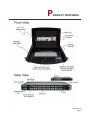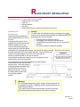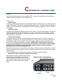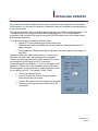
1
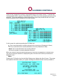
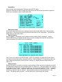
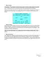
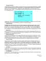
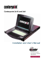
Centerpoint 2x16 and 2x8 Installation and User’s Manual Epicenter Inc. 211B Calle Pintoresco San Clemente, CA 92672 949-366-5370 www.epicenterinc.com Epicenter, Inc. Centerpoint User Guide © 2000 Epicenter, Inc. All rights reserved. First Edition July 2000 Pat # 6,609,034 The information contained in this guide is subject to change without notice. Epicenter Inc. shall not be liable for technical or editorial errors or omissions contained herein; nor is it liable for incidental or consequential damages resulting from the furnishing, performance, or use of this material. Product names mentioned herein may be trademarks and/or registered trademarks of their respective companies. PC/AT, PS/2 and RS/6000 are registered trademarks of International Business Machines Corporation. Sun Microsystems and Sun SPARC are registered trademarks of Sun Microsystems, Inc. Epicenter, Centerpoint, Centerview and Centercade are trademarks of Epicenter Inc. Epicenter Inc. 211B Calle Pintoresco San Clemente, CA 92672 Phone 949-366-5370 Fax 949-366-5380 Email [email protected] Web site www.epicenterinc.com PN:1100-00000294 Revision A2 T ABLE OF CONTENTS Introduction................................................................................................ 4 Using This Manual ..................................................................................... 5 Safety Warnings and Cautions................................................................... 6 Product Features ....................................................................................... 7 Rack Mount Installation.............................................................................. 8 Centerpoint Connections ....................................................................... 9 On-Screen Controls ................................................................................... 10 Operation................................................................................................... 14 TFT Setup and Controls............................................................................. 15 Appendices One Year Warranty ........................................................................ 17 Factory Default Settings ................................................................. 18 Installing Updates........................................................................... 19 Fuse replacement and Maintenance .............................................. 20 Regulatory Information ................................................................... 21 Specifications ................................................................................. 22 Connecting to a Sun Server ........................................................... 23 Epicenter, Inc. Page 3 I NTRODUCTION PRODUCT OVERVIEW The Fully Integrated KVM Solution Epicenter’s Centerpoint, 2x8 and 2x16 are Keyboard, Video and Mouse (KVM) solutions that integrate 16 or 8 port switches with a 14.1” TFT display, keyboard and mouse control in a single 1.75” high unit. Centerpoint is a one-stop solution to managing your rack-mounted servers. One control unit eliminates wasted rack space and provides you with control of up to 16 or more servers in a single, compact, design. FEATURES Fill your rack with processing power! As server density increases, giving up valuable rack space for management consoles becomes a critical issue. Centerpoint 2x8 and 2x16 can reduce the space requirements for your KVM switch, monitor, keyboard and mouse to only 1U. • • • • • • • • • • • • • 16 or 8 port keyboard, video and mouse (KVM) switch Access to any of the 8 or 16 ports by two users Integrated 14.1” flat panel display 1U rack mount chassis - 1.75" On-screen interface software for server selection Full 83 key, low-profile, notebook keyboard Glidepoint touch pad Unique high density cable design reduces cable clutter and eases installation Windows 98 and higher, Linux and Solaris compatible Includes all rack mounting hardware External video, keyboard and mouse ports for remote monitoring and control Option for built-in long line drivers for remote monitoring and control Multiple on-board processors monitor each port to assure availability Epicenter, Inc. Page 4 U SING THIS MANUAL This manual covers the Centerpoint 2x8 and Centerpoint 2x16 two-user models. Centerpoint 2x8 provides two user access to up to eight servers through the eight integral KVM ports. Centerpoint 2x16 provides two user access to up to 16 servers through the 16 integral KVM ports. Generally, all of this information in this user manual pertains to both products. However, the number of accessible ports ( 16 or 8) controls what will be seen on the On-Screen display. For example, in the section on On-Screen controls some of the sample screens show multiple pages to accommodate the 16 ports found on Centerpoint 2x16. If you are using the Centerpoint 2x8 models, only one page is required to display all of the available port options. Therefore, you will not see previous and next on those screens and only a single screen will be displayed. Epicenter, Inc. Page 5 S AFETY WARNINGS AND CAUTIONS DO NOT open top cover, Hazardous Voltages Present! When mounting Centerpoint 2x16 or Centerpoint 2x8 heating issues must be taken into account! Centerpoint 2x8 and Centerpoint 2x16 must be mounted in a way that ensures the integrity of the rack! Use caution when lowering monitor! Fingers may be pinched. Do not lean on drawer when pulled out! DO NOT OPEN CENTERPOINT. There are no user serviceable parts inside and opening or removing covers may expose you to dangerous shock hazards or other risks. Refer all servicing to qualified service personnel. • Do not spill any liquids into the cabinet or use your monitor near water. • Do not insert objects of any kind into the cabinet slots, as they may touch dangerous voltage points, which can be harmful or fatal or may cause electric shock, fire or equipment failure. • Do not place any heavy objects on the power cord. Damage to the cord may cause shock or fire. • Do not place this product on a sloping or unstable cart, stand or table, as the monitor may fall, causing serious damage to the monitor. When operating Centerpoint 2x16 or Centerpoint 2x8 with AC 208-240V power supply, use a power supply cord that matches and is properly rated for the AC power outlet being used. The power supply cord you use must have been approved by and comply with the safety standards of your country. The inside of the fluorescent tubes located within the LCD monitor contains mercury. Please follow the bylaws or rules of your municipality to dispose of the tube properly. Epicenter, Inc. Page 6 P RODUCT FEATURES Epicenter, Inc. Page 7 R ACK MOUNT INSTALLATION FOR INSTALLATION YOU WILL NEED THE FOLLOWING: • • • • • STANDARD 1U INSTALLATION Centerpoint 2x8 or 2x16 Product Power cord Rails with hardware User Guide Epicenter KVM Cables for connecting video, keyboard, and mouse Warning! To reduce the risk of personal injury or damage to the equipment, be sure that the following items are completed BEFORE performing any work on the rack: • The leveling jacks are extended to the floor. • The full weight of the rack rests on the leveling jacks. • The stabilizing feet are attached to the rack, if it is a single-rack installation. • The racks are coupled in multiple-rack installations. Use the following procedure to install Centerpoint 2x8 or 2x16 in the rack. Centerpoint 2x8 and 2x16 are shipped with the side-mount rails already installed on the unit. Insert a rack-mounting bracket into the rack at a level that will be comfortable for operating the keyboard, mouse and viewing the monitor. Align the screw holes at the front and back of the rack on both side rails. Use one screw to atImportant tach the mounting bracket to the front of the rack and two When mounting the rack slides screws to attach the slide to the rear of the rack. make sure that the end of the slides with the extension brackets are Once the rack mounts are in place you can now place the Ceninstalled to the rear of the rack. terpoint 2x8 or 2x16 unit in the rack. Leave the upper screen panel closed as you guide the rackmount slides into the rails mounted upon the rack. Once the system is in place depress the retaining buttons and slide the unit completely into the rack. Secure the outer slides in place with the included retention screws. Warning! The Centerpoint products weigh in excess of 30 pounds and can be awkward to handle. Handle the product carefully and use sensible lifting procedures. Take care to insure that the internal slide unit does not extend during transportation causing the unit to become unwieldy. Epicenter, Inc. Page 8 C ENTERPOINT CONNECTIONS POWER Check that the power switch is in the off position (O). Connect the included power cable to the receptacle located on the back of the Centerpoint unit. KVM CABLES Cable Lengths Cable length affects video quality as well as keyboard and mouse data timing. The maximum cable length is determined in part by the computer and peripherals used. Not all systems give satisfactory results at the maximum length. Standard Epicenter KVM cables are supplied in 6,9,12,15 and 20foot lengths. Cable Description Centerpoint uses proprietary cables to connect to PC servers. One end of the cable is a 15-pin connector that attaches to the rear of Centerpoint. The other end is split into 3 connectors; 1 15-pin VGA connector for attachment to a server’s video output; 1 PS/2 connector for the keyboard and 1 PS/2 connector for the mouse. Connecting the Cables First, power up the Centerpoint unit and optionally power down any or all computers that will be connected to Centerpoint. Then select the port that you wish to connect to on the Centerpoint unit and attach the single 15-pin connector. Once this is done, make the proper connections to the server’s video, mouse and keyboard receptacles. IMPORTANT – Insure that the single 15 pin connector of the KVM cable is connected to the Centerpoint unit first then connect the other end to the server's keyboard, mouse and video outputs. Failure to do so may result in damage to the server or the Centerpoint unit. Repeat the above process for each of the servers that you wish to connect to Centerpoint. Once all servers are connected you may then power up and boot each of the servers, if they are not already up and running. You may now proceed to configure the Centerpoint unit using its On-Screen Menu. Second User Video, Keyboard and Mouse Connections Standard video monitor, keyboard and mouse for the second user are located to the left of the KVM Connector ports at the back of the unit. To add the second user, simply connect an external video monitor, keyboard and mouse to these ports. Epicenter, Inc. Page 9 O N-SCREEN CONTROLS Control of the Centerpoint’s functions is accessed through our on-screen controls. To activate the Centerpoint Main Menu, press the Pause/Break key (or PrtSc key) in the top right hand corner of the keyboard. This screen displays the current status of the system and provides access to the other functions available on the Centerpoint On-Screen Display. On this screen the symbols preceding the Port Name are: : Port is connected and is currently selected by the current user (Characters in Green) +: Port is connected and is currently selected by user two (Characters in Red) Blank: Port is connected and is not currently selected X: No active system is currently attached to that port When two users are connected and accessing ports, each user is highlighted in a different color. The user’s current port selection is displayed in green, the other user’s current port selection is displayed in red. About Pressing the F10 function key from the Main Display menu displays the About Screen. This screen has important information about your system including the software release currently installed on Epicenter, Inc. Page 10 Setup Menu From the Main Menu pressing the F9 brings up the SETUP Menu. Select the item that you want to change by using the up and down arrow keys and then press the Enter Key to change the value of each option item. Edit System Name Edit System Name allows the user to assign a name for the current KVM switch. After selecting, simply type I n the name you choose to use and to then return to the Setup Menu. The name appears t the top of the main screen. Edit Port Names Edit Port Names 1-8 allows the user to assign a name to each of ports 1 through 8. Use the DOWN ARROW key to highlight the port name you wish to change and enter the desired name and/or description of the server up to 22 characters. Use F10 key to go back to the SETUP Menu. NOTE: The changes you make will not take permanent effect until you leave setup using the SAVE key. Edit Port Names F1-F8 allows the user to assign a name and description to each of ports 9 through 16. Repeat the same steps as Edit Port Names 1-8. Wakeup Server Because the server you switch to may have screen saving in effect, we have incorporated a method to automatically wake up the server’s display when you switch to it. This setting allows you to select the signals sent to the server to cause it to wake up. You can choose between “None” – no wakeup signal sent to server; “Shift” – a shift key code is sent to the server to wake it up; “CTRL” – sends a control key code to the server; “Mouse” – sends mouse movements, forward and back, to the server. The default setting is “None”. Use the Enter key to cycle through the choices. Epicenter, Inc. Page 11 Menu Position Adjust Menu Location displays a submenu that is used to adjust the position of the menu window on the display. It can be set for each port independently or the same setting applied to all of the ports. Use the arrow keys to move the menu box to the desired position on the display. When you are finished press the F11 to have the new position apply to all ports or the F10 key to apply only to the selected port. After pressing either F11 or F10 keys the SETUP Menu is displayed. Status Position Adjust Status Location displays a submenu that is used to adjust the position of the status window flag on the display. It can be set for each port independently or the same setting applied to all of the ports. Use the arrow keys to move the menu box to the desired position on the display. (See Adjust Menu Position screen above.) When you are finished press the F11 to have the new position apply to all ports or the F10 key to apply only to the selected port. After pressing either F11 or F10 keys the SETUP Menu is displayed. Menu Access Key Menu Access Key: Determines which keyboard key will activate the Centerpoint selection menu. If set to PAUSE, then the Pause/Break key will activate the Centerpoint menu. If set to PRTSCR then the Print Screen/Sys Rq key will activate the Centerpoint menu. Use the DOWN ARROW key to highlight the MENU ACCESS KEY field and press the ENTER key to toggle between the two options. Epicenter, Inc. Page 12 Change Password Change Password displays a submenu that allows the user to change the password that is needed to save the changes to any of the Setup changes. The submenu will prompt for the old password and then the new password twice. Highlight the OLD PASSWORD entry field and type the old password (default is blank). Then highlight the NEW PASSWORD entry field and type a password of 11 characters or less. Highlight the TYPE AGAIN entry field and retype the new password. Highlight the ACCEPT NEW PASSWORD and press the ENTER key to go back to the SETUP Menu. Status Displays Status Displays selects the information that will be displayed in the status window flag. If set to NUMBER, then upon closing the menu, a small status window flag will display the port number 1 through 8 or F1 through F8 indicating the active port. If set to NAME, then the name assigned to that port (Edit Port Names) will be displayed in the status window flag. Use the DOWN ARROW key to highlight the STATUS DISPLAYS field and press the ENTER key to display different options. Status Size Status Size determines the size of the status window flag in number of characters: the minimum is 2 and maximum is 22. Use the DOWN ARROW key to highlight the STATUS SIZE field and press the ENTER key to display different options. Status Background Status Background determines if the status window flag should be opaque or translucent in showing the port name or number. If set to TRANSL then the status window flag is translucent. If set to OPAQUE then the status window flag is opaque. Use the DOWN ARROW key to highlight the STATUS BACKGROUND field and press the ENTER key to toggle between the two options. Screen Timeout Screen timeout sets the number of minutes of inactivity after which the Centerpoint will invoke a sleep signal to the TFT. Setting a value of 0 disables the Timeout (not recommended). Pressing the Enter key changes the Timeout value. If the Timeout is less than 10, it increments in single units: between 10 and less than 60, it increments in units of 5: between 60 and less than 240, it increments in units of 10: and if it is 240 or greater, it returns to 0. In order to maximize the lifetime of the backlight we recommend the Timeout be set to 10 or less. F10-SAVE Pressing the F10 key prompts the user for a password match in order to save changes made in the setup menu. Type your password and enter to save all of your changes. Highlighting CANCEL will exit and return you to the SETUP Menu. F11-DISCARD Pressing the F11 key will cause all of your changes to be discarded, fall back to the last saved configuration and return to the Main Menu. Epicenter, Inc. Page 13 O PERATION Primary User GETTING STARTED Slide the inner drawer of the system out until the detents of the ball bearing slides catch. Open the TFT to a comfortable viewing angle. We suggests that all servers be set to 1024x768 resolution (optimal TFT performance) and that the refresh frequency be set to a level that creates a crisp video signal. INVOKE CENTERPOINT ON-SCREEN DISPLAY Press the Pause/Break key (or PrtSc if defined in SETUP menu) to bring up the MAIN MENU screen of the Centerpoint . From within the MAIN MENU the user can select a server by one of two ways; arrow keys and enter or to press the corresponding port key to immediately jump to that server. KEYBOARD The Centerpoint keyboard is a standard 83-key English laptop keyboard. When NumLk is invoked (LED will display on) the right side of the keyboard becomes a keypad for number entry. TOUCHPAD The touchpad buttons operate in a dual mode. The standard buttons directly below will activate right and left mouse clicks. Also a tap to the dark gray portion equals a left mouse click while tapping the light gray corner will create a right mouse click LEDS There are four LEDs on the Centerpoint unit Caps Lock, Scroll Lock, Number Lock and TFT indicator. When the keyboard functions are enabled the GREEN LED to the top right of the keyboard will illuminate. When the TFT is not receiving a signal but is powered the TFT indicator light will remain RED. This occurs when the TFT enters a sleep mode. When a signal is detected the LED will turn from RED to GREEN. TFT BUTTONS The four buttons to the right of the TFT control the TFT on-screen display. These buttons allow for screen adjustments including position, contrast and brightness. All of these functions within the TFT on-screen display are dedicated to the TFT. Second User As mentioned previously, all of the functionality available to the primary user is available to the second user. The only difference is that the second user accesses the system through secondary keyboard and mouse inputs and a second video output device or monitor. The second user has access to any of the active ports and to the setup menus as does the primary user. Each, however, is blocked from accessing the port that is actively being controlled by the other user. Epicenter, Inc. Page 14 TFT SETUP AND CONTROLS Control of the TFT functions, Brightness, Contrast, Clock, etc., is accessed through our on-screen controls. To activate the TFT on-screen display, press the enter key to the right of the display. The screen shows the current settings of the TFT display. These buttons provide access to screen adjustments including position, contrast and brightness and auto adjust. To access the on-screen TFT controls press the enter button. This brings up the display’s main menu. The first selection is the Auto Adjust function. Selecting this option brings up the Auto Adjust menu. Here you can select No or Yes using the up and down buttons. If you select Yes, the TFT will attempt to automatically detect your video output specifications and reset the TFT to match. If you want to manually adjust the other settings on the TFT simply select the item, Brightness, Clock, Position or Contrast and follow the on-screen options. Remember to use the TFT buttons next to the monitor screen, not the keyboard buttons. When you have completed your choices, the on-screen menu can be turned off by pressing the exit button. Epicenter, Inc. Page 15 A PPENDICES Epicenter, Inc. Page 16 O NE YEAR WARRANTY Epicenter, Inc. warrants this product against defects in materials and workmanship for one year. If a defect is discovered, Epicenter, Inc. will, at its option, repair or replace the product at no charge provided it is returned during the warranty period, with transportation charges prepaid. This warranty does not apply if the product has been damaged by accident, abuse, misuse, or misapplication; if the product has been modified without the written permission of Epicenter, Inc.; or if any Epicenter, Inc. serial number has been removed or defaced. THE WARRANTY AND REMEDIES SET FORTH ABOVE ARE EXCLUSIVE IN LIEU OF ALL OTHERS, WHETHER ORAL OR WRITTEN, EXPRESSED OR IMPLIED. EPICENTER, INC. SPECIFICALLY DISCLAIMS ANY AND ALL IMPLIED WARRANTIES, INCLUDING, WITHOUT LIMITATION, WARRANTIES OF MERCHANTABILITY AND FITNESS FOR A PARTICULAR PURPOSE. No Epicenter, Inc. dealer, agent or employee is authorized to make any modification, extension, or addition to this warranty. EPICENTER, INC. IS NOT RESPONSIBLE FOR SPECIAL, INCIDENTAL, OR CONSEQUENTIAL DAMAGES RESULTING FROM ANY BREACH OF WARRANTY, OR UNDER ANY OTHER LEGAL THEORY, INCLUDING BUT NOT LIMITED TO LOST PROFITS, DOWNTIME, GOODWILL, DAMAGE TO OR REPROGRAMMING, OR REPRODUCING AND PROGRAM OR DATA STORED IN OR USED WITH EPICENTER, INC. PRODUCTS. Some states do not allow the exclusion or limitation of incidental or consequential damages or exclusions of implied warranties, so the above limitations of exclusions may not apply to you. This warranty gives you specific legal rights, and you may have other rights that vary from state to state. Epicenter, Inc. Page 17 F ACTORY DEFAULT SETTINGS System Name = KVM Switch Port Names 1- 8 PORT-01-SERVERNAMEHERE PORT-02-SERVERNAMEHERE PORT-03-SERVERNAMEHERE PORT-04-SERVERNAMEHERE PORT-05-SERVERNAMEHERE PORT-06-SERVERNAMEHERE PORT-07-SERVERNAMEHERE PORT-08-SERVERNAMEHERE Port Names F1-F8 PORT-F1-SERVERNAMEHERE PORT-F2-SERVERNAMEHERE PORT-F3-SERVERNAMEHERE PORT-F4-SERVERNAMEHERE PORT-F5-SERVERNAMEHERE PORT-F6-SERVERNAMEHERE PORT-F7-SERVERNAMEHERE PORT-F8-SERVERNAMEHERE Wake Up Server = None Adjust Menu Offset Xpos=10 Ypos=8 for all ports Adjust Status Position Offset Xpos = 10 Ypos = 8 for all ports Menu Access Key = PAUSE Password = (BLANK) Status Shows Port = NUMBER Status Size = 2 Status Background = OPAQUE Screen Timeout = 20 Epicenter, Inc. Page 18 I NSTALLING UPDATES As new features become available Epicenter will occasionally release updates to the Centerpoint KVM software. You may want to update the Centerpoint firmware or software to take advantage of these improvements. The upgrade procedure can be completed quickly and easily via a Window-based application. The Centerpoint product is configured to allow direct downloading from a PC or a laptop that is connected to the Centerpoint through the serial port (RS232) located next to the external mouse and keyboard connectors. To update the firmware you need the following items: • Laptop or PC with available serial communication port • Standard serial cable (male DB9) that connects between Centerpoint and the PC or laptop computer • The Upgrade.exe Software provided by Epicenter Technical Support on the floppy or a hard drive Leave the Centerpoint KVM System power on. Disconnect or shut down all servers from the Centerpoint to be upgraded. Connect the serial upgrade (RS232) cable between the Centerpoint serial port to the Laptop or the PC's serial port. Locate the Upgrade.exe program. It can be on the floppy or the hard drive. Double click on the Upgrade.exe icon or file name. When it appears, use the pull-down to select Serial Port number on you laptop or the PC. For example: COM1, COM2 • • Click on the Upgrade button. • • Click the Exit button to exit the Upgrade.exe program. Click OK to close the Work on Progress window when the procedure is finished. Reconnect or boot up all servers connected to the Centerpoint. Epicenter, Inc. Page 19 F USE REPLACEMENT AND MAINTENANCE FUSE REPLACEMENT Centerpoint is equipped with fuse protection located next to the on-off switch. To assure proper operation of the unit and prevent possible damage or fire, always replace the fuse with the same specifications: Fuse Value: 250V, 2.0A Maximum CARE AND CLEANING Clean the LCD monitor surface with a lint-free, non-abrasive cloth. Avoid using any cleaning solution or glass cleaner! • Adjust the monitor’s brightness and contrast controls to enhance readability. • Avoid displaying fixed patterns on the monitor for long periods of time to avoid image persistence (after-image effects). ERGONOMICS To realize the maximum ergonomics benefits, we recommend the following: • Adjust the Brightness until the background raster disappears • Do not position the Contrast control to its maximum setting • Use the preset Size and Position controls with standard signals • Use the preset Color Setting • Use non-interlaced signals with a vertical refresh rate between 60-75Hz • Do not use primary color blue on a dark background, as it is difficult to see and may produce eye fatigue due to insufficient contrast Epicenter, Inc. Page 20 R EGULATORY INFORMATION Intended Use of Product: Video Display and Keyboard, and Mouse control Indoor Central Office Location Centerpoint is compliant with the following standards and specifications: European Union: Directive No. 89/336/EEC Electromagnetic Compatibility (EMC) as amended by 92/31/EEC and 93/68/EEC • • • • • • • • • • • EN 55022: 1998 +A1 +A2 Class A CISPR 22: 1997 EN 61000-3-2: 1995 EN 61000-3-3: 1995 EN 55024: 1998, EN 61000-4-2: 1995 EN 61000-4-3: 1995 EN 61000-4-4: 1995 EN 61000-4-5: 1995 EN 61000-4-6: 1995 EN 61000-4-11: 1994 Directive No. 73/23/EEC Low-Voltage-Directive (LVD), as amended by 93/68/ EEC for CE Marking • EN/IEC 60950:1992 +A1, +A2, +A3, +A4 The Technical Construction File is held by Epicenter, Inc., 211B Calle Pintoresco, San Clemente, CA 92672 International: • • • CISPR 22: 1997 Class A CISPR 24: 1997 IEC 950: 1992 +A1, +A2, +A3, +A4 United States Of America: • • UL Listed for I.T.E, E212076 FCC CFR 47 Part 15 Subpart B, Section 15.107(a) and Section 10.103(a), Class B Digital Device Epicenter, Inc. Page 21 S PECIFICATIONS ENVIRONMENTAL Temperature Operating: 32° to 104° F (0° to 40° C). Non-operating: -4° to 140° F (-20° C to 60° C). Humidity Non-condensing, operating: 10 to 90% Non-condensing, non-operating: 5 to 95% Altitude Operating: 0 to 10,000 ft (0 to 3048 m) Non-operating: 0 to 30,000 ft (0 to 9144 m) Audible Noise Less than 60 dbA. Heat Dissipation 85 Btu/hr maximum Shock Operating: 5 to 500 Hz, 0.5 g (0.1 oct/min) Non-operating: 5 to 100 Hz, 1 g (0.1 octave/min); 100 to 500 Hz, 1.5g (0.2 octave/min); 500 to 1000 Hz, 1.5 g (0.2 octave/min) ELECTRICAL Grounding Chassis grounded. Voltage 100 to 240V AC. Current .5 Amps at 240V AC up to 1 Amps at 100V AC. Line Frequency Single phase 50 or 60 Hz. COMPATIBILITY • • • • • XVGA 1024 x 768. SVGA 800 x 600. VGA 640 x 480 PS/2 Keyboard PS/2 Mouse Epicenter, Inc. Page 22 C ONNECTING TO A SUN SERVER SETTING UP THE VIDEO DISPLAY OPTION ON THE SERVER: If the server is running with an existing graphics monitor and resolution, please use the following step to change the resolution at the console and window mode: Note: The Sun device MUST be capable of running at 1024x768 resolution to display on a Centerpoint system. Hook up an external multi-sync XGA monitor (capable of 1280x1024 and higher). Power On the server. If the system is in autoboot mode then halt the system to get to the boot prompt (or console mode). At the boot prompt, type: >> setenv output-device screen:r1024x768x70 <return> Boot up the system. Logon to the Server as “root” Open a terminal session window and enter the following command lines: #cd /usr/sbin <return> #fbconfig –res 1024x768x70 <return> or #m64config –res 1024x768x70 <return> #cd /etc/openwin/server/etc <return> Edit the “owconfig” file and search for the string “TSIres”. Verify the string is set to 1024x768x70. If not then change it to 1024x768x70. Save the modified file. Reboot the system. At this time the TFT display should show the video properly. Remove the external monitor. CABLE CONNECTIONS Power down the Server and the Centerpoint unit. Plug one end of the Sun keyboard patch cable (mini din 8 pin connectors on both ends) to the keyboard port on the back of the Sun server and the other end to the input of the Sun-PS/2 Converter. Plug the HD15 video connector, from the end of the KVM cable that has 3 connectors (one for keyboard, one for mouse, and one for Video) to the HD15 video output on the Sun server. Plug the PS/2 keyboard connector of the KVM cable to the PS/2 connector that is marked for keyboard of the Sun-PS/2 Converter box. Plug the PS/2 mouse connector of the KVM cable to the PS/2 connector that was marked for mouse of the Sun-PS/2 Converter box. Plug the single ended HD15 connector of the KVM cable to the desired port on the Centerpoint unit Epicenter, Inc. Page 23 Once all connections are complete: • Power ON the Centerpoint unit. • Press the Pause/Break key and choose the port number that the Sun server is attached to and press return. • Power ON the Server. The server is ready for entering the Boot command. TROUBLE SHOOTING If these steps do not allow the Sun to be displayed please follow these steps: • • • Check ALL cable connections using information provided in Cable Connections section. Attach a Multi-Sync Monitor to the External Video Port on the Centerpoint. Using the keyboard and the touchpad of the Centerpoint to boot the Server and verify the current resolutions of the console and window modes. If they are not set to 1024x768 70 Hz repeat steps that change the resolution. Reboot the Server. KEYBOARD MAPPING Special keys on the Sun keyboard are mapped to the following on the Centerpoint keyboard. Sun Key Stop Again Props Undo Front Copy Open Paste Find Cut Help Right ♦ Left ♦ Compose Alt Graph Centerpoint Keyboard R_CTRL & F1 R_CTRL & F2 R_CTRL & F3 R_CTRL & F4 R_CTRL & F5 R_CTRL & F6 R_CTRL & F7 R_CTRL & F8 R_CTRL & F9 R_CTRL & F11 R_CTRL & H Right WINDOWS Key Left Windows Key WIN CMD R_ALT Epicenter, Inc. Page 24 Epicenter Inc. 211B Calle Pintoresco San Clemente, CA 92672 949-366-5370 www.epicenterinc.com Epicenter, Inc. Page 25