1
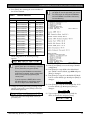
Conettix DX4020
Installation Guide
EN
Network Interface
Module
Conettix DX4020 | Installation Guide | Contents
Contents
1.0
2.0
3.0
3.1
3.2
4.0
4.1
4.2
4.3
4.4
5.0
5.1
5.2
6.0
6.1
6.2
6.3
6.4
6.4.1
6.4.2
6.5
6.5.1
6.5.2
7.0
8.0
2
Introduction ........................................................................................................................................................ 4
Overview ............................................................................................................................................................. 4
Installation........................................................................................................................................................... 5
Mounting............................................................................................................................................................... 5
Wiring.................................................................................................................................................................... 5
DIP Switch Settings ........................................................................................................................................... 7
GV2 Series, G Series, and 9000 Series Control Panels .................................................................................... 7
DS7240V2, DS7220V2, and Easy Series V3+ (ICP-EZM2) Control Panels ................................................ 7
DS7400Xi Control Panel..................................................................................................................................... 8
FPD-7024 Control Panel ..................................................................................................................................... 8
LEDs...................................................................................................................................................................... 8
Ethernet and Serial............................................................................................................................................... 8
XPort ..................................................................................................................................................................... 9
IP Address Programming ................................................................................................................................. 9
Factory-Programmed IP Configuration ............................................................................................................. 9
Identifying the MAC Hardware Address .......................................................................................................... 9
Obtaining an IP Address ..................................................................................................................................... 9
Assigning the Initial IP Address ....................................................................................................................... 10
ARP Command Overview ................................................................................................................................ 10
Using the ARP Command ................................................................................................................................ 10
Using Telnet to Complete Configuration ........................................................................................................ 11
Using Windows 98 Telnet ................................................................................................................................. 11
Using Windows 2000/XP Telnet...................................................................................................................... 15
Control Panel Programming ......................................................................................................................... 16
Specifications .................................................................................................................................................... 16
Bosch Security Systems, Inc. | 1/09 | F01U045288-05
Conettix DX4020 | Installation Guide | Trademarks
.
Certifications and Approvals
Trademarks
•
Microsoft® and Windows® are either registered
trademarks or trademarks of Microsoft
Corporation in the United States and/or other
countries.
Lantronix® is a registered trademark of Lantronix
Corporation, registered in the U.S. and other
countries.
XPort™ with its patent-pending technology is a
trademark of Lantronix, Inc.
•
•
For Underwriters Laboratories, Inc. (UL)
Listed fire Installations, ensure that the
shared on-premises communications
equipment is UL Listed for information
technology equipment.
Set the parameters in the RADXAUX1 or
GV2AUX section of the control panels
(Table 1).
The GV2AUX handler is used for GV2
Series control panels. The RADXAUX1
handler is used for G Series control panels.
Table 1:
Control Panel RADXAUX1 or GV2AUX
UL Parameters
RADXAUX1
GV2AUX
Parameter
Control Panel on Protected Premises1
UL1610 Line Security
Intrusion System
Installations
UL864 Fire
Digital
No Digital
Systems
Dialer
Dialer
Installations2
Backup
Backup
Poll Rate
ACK Wait
Retry Count
75 sec
13 sec
5
2.
240 sec
13 sec
5
•
•
•
•
•
•
•
•
UL Requirements
1.
UL Standards
75 sec
13 sec
5
1
For local annunciation, G Series control panels require
Firmware Version 6.9 or higher. GV2 Series control panels
require Version 7.04 or later.
2
Install the system according to NFPA-72.
UL294, Access Control Systems Units
UL864, UL Commercial Fire Alarm signaling
UL365, Police Station Burglar Alarm Units and
Systems
UL609, Local Burglar Alarm Units and Systems
UL985, Household Fire Warning System Units
UL1023, Household Burglar-alarm System Units
UL1076, Proprietary Burglar Alarm Units and
Systems
UL1610, Central Station Burglary, Line Security
ULC Standards
•
•
•
•
•
CAN/ULC-S303-M91, Local Burglar Alarm Units
and Systems
CAN/ULC-S304-M88, Central and Monitoring
Station Burglar Alarm Units
CAN/ULC-S545, Residential Fire Warning System
Control Units
ULC/ORD-C1076-M1986, Proprietary Burglar
Alarm Units and Systems Communicator
ULC-C1023-1974, Household Burglar Alarm
Systems
Approvals
•
•
•
CSFM
NF A2P Type 2 Certification number:
122000076-05
• FM*
* When used with the Conettix D6600
Communications Receiver/Gateway.
Refer to the D6200 Software Operation
and Installation Guide (P/N: 4998154991)
to configure the D6600/D6100i
Communication Receiver/Gateway to
receive UL Listed communications from a
DX4020.
Add a Telnet password to the DX4020
communications protocol. To complete the
configuration, refer to Section 6.5 Using Telnet to
Complete Configuration, page 11.
Keep your password for future reference.
Bosch Security Systems, Inc. | 1/09 | F01U045288-05
3
Conettix DX4020 | Installation Guide | 1.0 Introduction
1.0 Introduction
2.0 Overview
Use the Conettix DX4020 Ethernet Network Interface
Module (Figure 1) for bi-directional communications
over Ethernet networks. Generally, you use the
DX4020 in PC front-end software packages such as:
• Conettix D6600 Communications
Receiver/Gateway reporting
• History retrieval
• Building Integration System (BIS) and PC9000
• Remote Programming Software (RPS) connection
for control panel programming
• Diagnostic troubleshooting
Refer to Figure 2 for general system connections. The
main components are:
• Compatible control panel
• Conettix DX4020 Ethernet Network Interface
Module
• Conettix D6600 Communications Receiver/
Gateway
• Conettix D6680 Ethernet Network Adapter
• Conettix D6100i Communications
Receiver/Gateway
Figure 2:
Figure 1:
System Connections Overview
DX4020 Network Interface Module
3
1
2
2
1
4
12
13
5
6
11
9
8
7
10
3
4
5
6
1 - Lantronix® XPort™ network interface module
(NIM)
2 - Erasable programmable read only memory
(EPROM)
3 - Data bus
4 - DIP switches
5 - Serial and bus LEDs
6 - P2 Jumper
Failure to follow these instructions can
result in a failure to initiate alarm conditions.
Bosch Security Systems, Inc. is not
responsible for improperly installed, tested,
or maintained devices.
Follow these instructions to avoid
personal injury and damage to the
equipment.
4
7
1 - Compatible control panel
2 - Compatible control panel data bus to the
DX4020 data bus terminals connection
3 - DX4020 Network Interface Module
4 - DX4020 to Ethernet connection
5 - Ethernet network
6 - Ethernet network to the D6100i connection
7 - Conettix D6100i Communications
Receiver/Gateway
8 - Ethernet network to the D6680/D6682
connection
9 - D6680/D6682 Ethernet Network Adapter
10 - Conettix D6600 Communications
Receiver/Gateway
11 - D6680 to the D6600 COM4 Port connection
12 - Ethernet network to Host PC Ethernet network
interface card (NIC) connection
13 - Host PC running D6200 Programming
Administrative Software
Bosch Security Systems, Inc. | 1/09 | F01U045288-05
Conettix DX4020 | Installation Guide | 3.0 Installation
.
3.0 Installation
Inform the operator and the local authority
having jurisdiction (AHJ) before installing
the DX4020 in an existing system.
Disconnect all power to the control panel
before installing the DX4020.
3.2
Wiring
Run the wiring connections from the DX4020 data bus
terminals to the compatible control panel’s data bus
terminals (Figure 4). Refer to the associated control
panel documentation for complete wiring instructions.
Figure 4:
DX4020 to Control Panel SDI, Option,
and Data Bus Wiring
Before installing the DX4020, refer to
Table 7 on page 16 for control panel
compatibility information.
3.1
1
2
Mounting
3
Mount the DX4020 inside the control panel enclosure
using any of the standard three-point mounting
patterns (Figure 3). Refer to the associated control panel
documentation for complete installation instructions.
Figure 3:
4
5
6
Mounting Holes
1
1 - DX4020 data bus
terminals
2 - Compatible control
panel SDI, option,
and data bus
terminals
3456-
Black (-) wire
Green (G) data wire
Yellow (Y) data wire
Red (+)wire
1 - Mounting holes (3)
Use an AE1 or AE2 Enclosure when
mounting the DX4020 in a separate
enclosure. Ensure that all external wiring
between and originating from the
enclosures is in a metal conduit no longer
than 6 m (20 ft).
Bosch Security Systems, Inc. | 1/09 | F01U045288-05
5
Conettix DX4020 | Installation Guide | 3.0 Installation
Figure 5 shows an example of wiring the DX4020 to a control panel.
Figure 5:
Wiring the DX4020 to a Control Panel
4
1
2
3
43489F
LEDs Off When Normal
YEL
RED
Charging Status
Low Battery - 12.1 VDC
Digital Alarm Communicator Transmitter
1
2
CAUTION: See Manual For Power Requirements Relating to Terminals
+ AUX POWER
4
BATTERY NEGATIVE ONLY
5
Maximum Charging
Current 1.4 Amps.
BATTERY POSITIVE ONLY
6
RELAY A
7
RELAY B
8
RELAY C
9
10
PROGRAMMABLE
ALARM OUTPUTS
Terminals
7 & 8
Requires Optional
D136 Relay
In ALT ALARM
& SW AUX
PERIPHERAL DEVICE CONNECTIONS
POWER SUPPLY REQUIREMENTS
The Power Supply Provides a Maximum of 1.4 Amps For The Control
Panel and All Accessory Devices. For System Loading, See OperationInstallation Manual #43488 ___.
All External Connections Except Terminal 5 (Battery Positive) Are
Inherently Power Limited.
Requirements For Battery Standby Time May Reduce Allowable Output.
CLASS 2 TRANSFORMER
16.5 VAC 40 VA 60 Hz
Part No. D1640
Internally Fused - Do Not short
Requires Unswitched Outlet
Do Not Share With Other Equipment
3
Reset Pin
Disable All Except Battery
Charging And Programming
Reference Manual #43494 ___ For System Wiring Diagram, Issue A
Reference Document #33284 ___ For Compatible Smoke Detectors
10.2 VDC - Battery Load Shed
RED
6
WARNING!
Battery: Replace Every 3 to
Multi-Battery Installation Requires
Model No. D122 Dual Battery Harness. 5 years with Model D126, 12 V
7 Amp Hr Lead Acid Battery
Improper Installation Can Be a Fire
Hazard.
This equipment should be installed in accordance with the NFPA 70 (National Electrical Code)
and NFPA 72 (National Fire Alarm Code) for Local, Central Station, Remote Station and Household Fire
Warning Systems and under the limits of the Local Authority Having Jurisdiction (National Fire
Protection Association, Batterymarch Park, Quincy, MA 02269) Printed information describing proper
installation, operation, testing, maintenance, evacuation planning and repair service is to be provided
with this equipment.
31
DATA BUS B
30
BLACK
COMMON
29
N.F.P.A.
Style 3.5
Signaling
Line
Circuits
ZONEX OUT 1
Point 3 Point 4
Point 5 Point 6
Point 7 Point 8
PHONE MONITOR SELECT
LOOP START
GND START
11
12
13
14
15
16
17
18
19
20
21
22
27
ZONEX OUT 2
26
ZONEX IN 2
25
ZONEX COMMON
Point 8
GND FAULT
Detect
D
E
I
N
S
A
A
B
B
L
L
E
E
28
ZONEX IN 1
ZONEX POWER +
VOLTAGE RANGES
Open
3.7 - 5.0 VDC
Normal
2.0 - 3.0 VDC
Short
0.0 - 1.3 VDC
Point 1 Point 2
32
DATA BUS A
GREEN
System is Intended To Be Checked By A Qualified Technician At Least Every 3 Years.
The types of initiating circuits that the panel has been approved for are A, M, W, SS.
COMMON
GROUND START
RED PHONE
R equires
LED
Relay # D136 in ON WHEN
Ground
COMMUNICATING
Start Socket
OFF WHEN IDLE
POWER +
YELLOW
D9412G Control / Communicator is UL Listed For Central Station, Local, Remote Station and Household
Fire Alarm, and Central Station, Local, Police Station Connect and Household Burglar Alarm.
EARTH GROUND
GROUND FAULT DETECT
Enabled
Disabled
8
7
24
23
PROG
CONN
GRN
-
7
+
5
6
1234-
D9412G Control Panel*
D8103 or D8109 Enclosure
DX4020 location in control panel enclosure
DX4020 (not in scale with control panel)
5678-
To Ethernet network
Battery
To AC transformer
Non-power limited area. Keep all power wiring
out of this area
* The D9412G is used as an example.
Table 2 lists the connection sequences.
Table 2:
6
Wiring Connections (DX4020 to Control Panels)
Sequence Number
DX4020 Connection
Control Panel Connection
1
XPort Ethernet
to
2
3
4
5
R Terminal
Y Terminal
G Terminal
B Terminal
to
to
to
to
Other
Local-area network (LAN)/wide-area
network (WAN)
POWER + (Terminal 32)
DATA BUS A (Terminal 31)
DATA BUS B (Terminal 30)
COMMON (Terminal 29)
Bosch Security Systems, Inc. | 1/09 | F01U045288-05
Conettix DX4020 | Installation Guide | 4.0 DIP Switch Settings
.
Figure 7:
4.0 DIP Switch Settings
Use the DIP switch settings in Sections 4.1 through 4.4
for the DX4020 network communication.
4.1
DIP Switch Setting for Address 88
1
=
2
=
GV2 Series, G Series, and 9000
Series Control Panels
The GV2 Series consists of the following control
panels:
• D9412GV2
• D7412GV2
• D7212GV2
The G Series consists of the following control panels:
• D9412G
• D7412G
• D7212G
The 9000 Series consists of the following control
panels:
• D9412
• D7212
• D7212
• D9112
For proper network communication
between the DX4020 and the control panel,
the D9412G, D7412G, D7212G, D9412,
D7412, D7212, and D9112 require
firmware revision 6.3 or later.
Use SDI Bus Address 80 (Figure 6) with the DX4020
and PC9000. Use SDI Bus Address 88 (Figure 7) with
the DX4020 and RPS, or for network communication.
Figure 6:
1 2 3 4 5 6 7 8
1 - ON (down)
4.2
2 - OFF (up)
DS7240V2, DS7220V2, and Easy
Series V3+ (ICP-EZM2) Control
Panels
For proper network communication
between the DX4020 and the control panel:
-
The DS7240V2 and DS7220V2 require
firmware revision 2.xx or later.
-
The Easy Series (ICP-EZM2) control
panel requires firmware version 3.0 or
later, and the DX4020 requires firmware
version 2.23 or later.
For network communication, set the DIP switches on
the DX4020 to Address 134 (Figure 8) when using the
DS7240V2, DS7220V2, or Easy Series V3+ control
panels.
Figure 8:
DIP Switch Setting for Address 134
1
=
2
=
DIP Switch Setting for Address 80
1
=
2
=
1 2 3 4 5 6 7 8
1 - ON (down)
2 - OFF (up)
1 2 3 4 5 6 7 8
1 - ON (down)
2 - OFF (up)
Bosch Security Systems, Inc. | 1/09 | F01U045288-05
7
Conettix DX4020 | Installation Guide | 5.0 LEDs
4.3
DS7400Xi Control Panel
Use Option Bus Addresses 13 and 14 (Figure 9 and
Figure 10) to send reports. Use Option Bus Address 13
to connect to the RPS for remote programming.
Figure 9:
DIP Switch Setting for Address 13
1
=
2
=
5.0 LEDs
5.1
Ethernet and Serial
Figure 12 and in Table 3 identify and describe the
DX4020’s four bus and serial status LEDs.
Use the P2 jumper to enable (jumper on) or disable
(jumper off) LED operation.
Figure 12: Ethernet and Serial LEDs
1 2 3 4 5 6 7 8
1 - ON (down)
2 - OFF (up)
Figure 10: DIP Switch Setting for Address 14
1
=
2
=
1
3
4
1 2 3 4 5 6 7 8
2
1 - ON (down)
4.4
2 - OFF (up)
FPD-7024 Control Panel
For proper network communication
between the DX4020 and the FPD-7024
Control Panel, the DX4020 requires
firmware revision 2.21 or later.
Use Option Bus Address 250 (Figure 11) when using the
DX4020 with an FPD-7024 Control Panel.
Figure 11: DIP Switch Setting for Address 250
1
=
2
1 2 3 4 5 6 7 8
1 - ON (down)
8
2 - OFF (up)
1 - Ethernet and serial
LEDs
2 - P2 jumper
Table 3:
3 - LED enabled
4 - LED disabled
Bus and Serial Status LEDs
LED
Name
Color
Function
1
BUS-XMIT
Red
2
BUS-RCV
Red
3
SER-RX
Green
4
SER-TX
Green
Flashes when the data bus
sends a message.
Flashes when the data bus
receives a message.
Flashes every time a
message is received from
the Ethernet port.
Flashes when a message is
sent to the Ethernet port.
=
Bosch Security Systems, Inc. | 1/09 | F01U045288-05
Conettix DX4020 | Installation Guide | 6.0 IP Address Programming
.
5.2
6.1
XPort
Figure 13 and Table 4 identify and describe the
DX4020’s two bi-color LEDs that are built into the
front of the XPort connector.
Figure 13: XPort LEDs
2
1
Factory-Programmed IP
Configuration
The DX4020 is shipped with the following default IP
settings:
• Default IP Configuration Number: DHCP
• Default Port: 7700
• Default DHCP Device Name: Cxxxxxx
xxxxxx = last six digits of the MAC address
6.2
Identifying the MAC Hardware
Address
The MAC address is hard-coded into the DX4020
during its manufacture and cannot be changed. This
address is six bytes (twelve digits) long.
1 - Link LED
Table 4:
2 - Activity LED
The MAC address label is affixed to the XPort
connector (Figure 14).
XPort LEDs
Figure 14: MAC Address Location
Link LED
Activity LED
Color
Indicates
Color
Indicates
Off
Amber
Green
No link
10 Mbps
100 Mbps
Off
Amber
Green
No activity
Half duplex
Full duplex
6.0 IP Address Programming
Use this section to configure the DX4020 with a
network IP address. Use resident commands and
programs such as the ARP and ping commands, and
the telnet program available in the Microsoft
Windows® operating system.
The IP, MAC address, and port number
used in this document are for demonstration
only.
A working knowledge of DOS commands,
Windows, networks, and their operation is
required.
If your installation uses Dynamic Host
Configuration Protocol (DHCP) to obtain an
IP address and Port 7700 for
communication, refer to the associated
control panel documentation for instructions
unless you plan to use RPS over the
network through the DX4020. If using RPS,
proceed to Section 6.1 FactoryProgrammed IP Configuration.
Bosch Security Systems, Inc. | 1/09 | F01U045288-05
6.3
Obtaining an IP Address
Give the network administrator the MAC address. He
or she assigns an IP address to your DX4020.
An IP address is an identifier for a computer or device
on a transmission control protocol/internet protocol
(TCP/IP) network. Networks using TCP/IP route
messages based on the destination’s IP address. The IP
address format is a 32-bit numeric address written as
four numbers separated by periods ranging from 0 to
255, such as 172.17.10.70. Within an isolated
network, you can assign IP addresses at random
providing each address is unique. To avoid duplicate
addresses, use registered IP addresses (Internet
Protocol addresses) when connecting a private network
to the Internet.
9
Conettix DX4020 | Installation Guide | 6.0 IP Address Programming
6.4
Assigning the Initial IP Address
Before proceeding, read this entire section.
Ensure that the DX4020 has power and the
Ethernet Network RJ-45 connection is in
place.
Ensure that the PC used to configure the
DX4020 and the DX4020 itself are on the
same gateway (the device connecting the
LAN to the WAN).
6.4.2
1.
From the Start Menu, select Start Æ Run to open
a DOS window.
2.
At the Run dialog box, type COMMAND and
click [OK].
A DOS window appears.
1.
At the DOS command line, type arp –s
172.17.10.70 00-20-4a-12-04-0e and press [Enter].
3.
In this example, 172.17.10.70 is the IP address
from the network administrator and 00-20-4a-1204-0e is the DX4020 MAC hardware address.
Use Telnet to configure the DX4020’s
communications parameters.
When the DX4020 is configured and has
an IP address, you can use Telnet from
anywhere on the network to change the
configuration parameters.
6.4.1
ARP Command Overview
When you have received a valid IP address from the
network administrator, open the DOS prompt (from
Windows) on any PC connected to the network you
are using.
Using the ARP Command
The system does not indicate that the
operation was properly performed. The
absence of an error message indicates the
function is correct.
4.
Verify that the IP address was correctly entered in
the ARP table by typing arp -g and pressing
[Enter].
The following message appears.
Temporarily assign the DX4020 IP address to its
hardware address on the Host PC using ARP. During
installation, the ARP is installed by default in the
\WINDOWS directory (Windows 98, Windows
Millennium) or the \WINNT directory (Windows 2000
and Windows XP).
At the DOS prompt (usually C:\windows) use the
command syntax shown in Figure 15.
Figure 15: ARP.EXE Command Syntax
1
arp - s
1
2
xxx. xxx. xxx. xxx
2
zz- zz- zz- zz- zz- zz
xxx.xxx.xxx.xxx (The IP address assigned to the
DX4020 by the network administrator.)
zz-zz-zz-zz-zz-zz (The MAC hardware address
on the DX4020 XPort NIM.)
Section 6.4.2 describes how to assign an IP address to a
DX4020 NIM using the ARP command.
10
This message shows the Internet address (IP address)
and the corresponding physical address (MAC
hardware address). The third line in the table shows the
arp MAC address of 00-20-4a-51-19-8c is temporarily
linked to IP address 172.17.10.70.
The network uses this table to identify devices and
route signals. The number of devices and other types,
such as dynamic, depends on the network and the
number and type of devices the PC communicated
with. You must identify the MAC address of the device
you are installing and verify it has an IP address linked
to it.
Bosch Security Systems, Inc. | 1/09 | F01U045288-05
Conettix DX4020 | Installation Guide | 6.0 IP Address Programming
.
6.5
Using Telnet to Complete
Configuration
6.
Click Connect and wait a few seconds for the
following failed message to appear.
7.
Click OK to open the Telnet window again.
8.
Repeat Step 3 in Section 6.4.2 Using the ARP
Command, on page 10.
9.
This time, leave all but the Port field the same.
Type 9999 in the Port field.
Refer to Section 6.5.1 Using Windows 98 Telnet when
using Windows 98.
Refer to Section 6.5.2 Using Windows 2000/XP Telnet
beginning on page 15 when using Windows 2000/XP.
6.5.1
Using Windows 98 Telnet
1.
At the Start Menu, select Start Æ Run to open a
DOS window.
2.
At the Run dialog box, type telnet and press
[Enter] to start the telnet application.
3.
Select Connect Æ Remote System...
The Connect window opens.
10. Click Connect.
4.
At the Host Name field, type the DX4020 IP
address assigned in the previous section.
11. Press [Enter].
If you do not press [Enter] within 5 sec of
seeing the “Press Enter to go into Setup
Mode” message, the system disconnects
you and the following message appears.
In this example, the IP address is 172.17.10.70.
5.
At the Port field, type 1 and leave the TermType
field at vt100.
Bosch Security Systems, Inc. | 1/09 | F01U045288-05
11
Conettix DX4020 | Installation Guide | 6.0 IP Address Programming
If you press [Enter] within 5 sec. of seeing the
“Press Enter to go into Setup Mode” message, the
following screen appears.
12. Press [0] then [Enter] to set up the basic Server
configuration.
If the DX4020 was previously programmed with
an IP address, it appears in parentheses. For
example, if the DX4020 was originally
programmed to IP address 172.30.3.36, change it
to 190.200.128.219.
13. Press [1][9][0][.][2][0][0][.][1][2 [8][.][2][1][9][Enter]
to program IP Address 190.200.128.219.
14. When using DHCP, press [0][.][0][.][0][.][0][Enter].
15. When prompted to set the Gateway address:
-
If the Gateway address is not required or if
using DHCP, type N and press [Enter].
-
If the Gateway address is required, type Y and
the Gateway IP address 190.200.128.1. Then
press [Enter].
The Gateway IP is required only when using
a WAN. In a LAN, the Gateway IP is
generally not required.
The following message appears.
16. If the Netmask requires changing from the default,
enter the number of bits that corresponds to the
Netmask your network is using (Table 5). Press
[Enter] when using DHCP.
See your network administrator for more
information.
12
Bosch Security Systems, Inc. | 1/09 | F01U045288-05
Conettix DX4020 | Installation Guide | 6.0 IP Address Programming
.
17. Press [Enter] after entering the correct number of
bits for the Netmask.
Table 5:
Netmask Addresses
Host Bits
Netmask
Host Bits
Netmask
1
2
3
4
5
6
7
8
9
10
11
12
13
14
15
16
255.255.255.254
255.255.255.252
255.255.255.248
255.255.255.240
255.255.255.224
255.255.255.192
255.255.255.128
255.255.255.0
255.255.254.0
255.255.252.0
255.255.248.0
255.255.240.0
255.255.224.0
255.255.192.0
255.255.128.0
255.255.0.0
17
18
19
20
21
22
23
24
25
26
27
28
29
30
31
255.254.0.0
255.252.0.0
255.248.0.0
255.240.0.0
255.224.0.0
255.192.0.0
255.128.0.0
255.0.0.0
254.0.0.0
252.0.0.0
248.0.0.0
240.0.0.0
224.0.0.0
192.0.0.0
128.0.0.0
Keep your password in a secure place. If
you forget or lose the password, you cannot
use Telnet again to configure the DX4020
until the DX4020 is returned to the factory
for reconditioning.
When using DHCP, the following message
appears:
To assign a device name for use on a LAN,
type Y, enter up to 16 characters, and press
[Enter]. Otherwise, only press [Enter].
When using the DX4020 to communicate
to RPS over a network, enter a unique name
known to the person programming the
control panel.
If you do not enter a DHCP device name,
the default Cxxxxxx is used (where xxxxxx is
the last six digits of the MAC address).
18. Change the Telnet password by pressing [Y] and
entering a password or press [Enter] to leave the
default telnet password.
This screen shows the Setup Mode screen you
previously saw.
Bosch Security Systems, Inc. | 1/09 | F01U045288-05
19. Press [1] and [Enter] to access the setup Channel 1
configuration.
20. Press [Enter] to accept 9600 as the default baud
rate. If 9600 is not the default, type 9600 and press
[Enter] to change it.
21. Press [Enter] to accept 4C as the default I/F Mode.
If 4C is not the default, type 4c and press [Enter] to
change it.
22. Press [Enter] to accept 00 as the default flow. If 00
is not the default, type 00 and press [Enter] to
change it.
23. Type a unique port number for the LAN the
device is connected to and press [Enter].
13
Conettix DX4020 | Installation Guide | 6.0 IP Address Programming
24. Press [Enter] to accept CC as the default
ConnectMode. If CC is not the default, type cc
and press [Enter] to change it.
26. Press [Enter] four times to specify 0.0.0.0 for
remote IP address.
25. Enter the appropriate Datagram value based on the
type of control panel. Refer to Table 6.
28. To enable encryption, select 6- Security from the
Main Menu and follow Steps 29 through 33.
Table 6:
If encryption is enabled on the DX4020 it
must be enabled at the D6680/D6682 or
D6100i-E120 with the same key.
Entering Datagram Values
Control Panel Type
Do Step:
DS7240V2/DS7220V2
FPD-7024
D9412GV2/D7412GV2/D7212GV2 with
firmware version 7.06 or later
D9412G/D7412G with firmware version 7.00
or later
D7212G with firmware version 7.01 or later
D9412/D7412/D7212/D9112/D9124 with
firmware version 7.00 or later
Easy Series with firmware version 3.0 or later
25a
25a
DS7400XiV4+
25b
D9412GV2/D7412GV2/D7212GV2 with
firmware version 7.05 or earlier
D9412G/D7412G with firmware version 6.90
or earlier
D7212G with firmware version 6.91 or earlier
D9412/D7412/D7212/D9112/D9124 with
firmware version 6.90 or earlier
a.
27. Enter the same port number used for the
D6680/D6682 or D6100i.
The software revision of the NIM attached
to the DX4020 must be 1.5d or later.
Check the version by starting a Telnet
session with the unit and allowing the
version to appear for 5 sec before pressing
[Enter].
25a
25a
25a
25a
25a
25b
25b
25b
25b
Type 02 and go to Step 28.
Datagram 02 on the 9000, G, or GV2
Series control panels requires RPS version
5.5 or later.
29. Press [Enter] after the each of the following
prompts:
-
Disable SNMP (N) N
-
Disable SNMP Community Name ( ):
-
Disable Telnet Setup (N) N
-
Disable Port 77FEh (N) N
b. If the unique port number previously entered
is the same as the D6680 or D6100i, type 00
and go to Step 28. Otherwise, type 07 and go to
Step 26.
To use Datagram 02 or 07, you must have
Bosch firmware version 1.5d or later in the
XPort Module. Public versions of the
Lantronix firmware, including version 1.8,
are not compatible with these datagrams.
Refer to the DeviceInstaller Operation and
Installation Guide (P/N: 4998138688) for
more information.
Refer to the Conettix D6600 System Guide
(P/N: 4998122712) for more information
on datagram types.
14
Disabling both the telnet and port 77FE
prevents you from accessing the set-up
menu for future changes.
-
Disable Web Server (N) N
-
Disable ECHO ports (Y) Y
30. At Enable Encryption (N), press [Y].
31. At Key length in bits (0), type 128 and press
[Enter].
32. At Change keys (N), press [Y].
33. Enter the bytes programmed in the D6680. These
16 bytes (32 characters) should match. The default
value is 01-02-03-04-05-06-07-08-09-10-11-12-1314-15-16.
34. At Enable Enhanced Password (N), press [Enter].
Bosch Security Systems, Inc. | 1/09 | F01U045288-05
Conettix DX4020 | Installation Guide | 6.0 IP Address Programming
.
35. At the Main Menu, select 9 to save and close the
telnet session.
The following message appears.
4.
At the Microsoft Telnet> prompt, type open
(space) IP ADRESS (space) PORT NUMBER,
such as open 172.17.10.70 1.
The connection fails the first time. This is normal.
36. Click OK to close the telnet window.
5.
37. To verify that the IP address is properly
configured, ping the IP address and check for a
response.
-
At the C:\> prompt, type PING <IP
Address> and press [Enter].
-
Four reply messages appear, verifying the
DX4020 is communicating with the network.
-
DX4020 configuration is complete. Perform
this procedure for additional DX4020s.
6.5.2
Pressing [F3] shows the last line typed,
Backspace over the port entry, and change
it to 9999.
Using Windows 2000/XP Telnet
To complete the DX4020 IP address configuration, you
must launch a telnet session.
6.
Press [Enter] to return to the DX4020 Setup Menu.
7.
To program a device, follow Steps 11 through 35 in
Section 6.5.1 Using Windows 98 Telnet, starting on
page 11.
8.
Close Telnet by clicking the
right-hand corner.
Ensure that you are logged into Windows
2000 or XP with an administrator privilege
level.
The following example uses the IP address
of 172.17.10.70 and the MAC Address of
00-20-4a-72-04-0e.
1.
At the Start Menu, select Start Æ Run to open a
DOS window.
2.
At the Run dialog box, type COMMAND and
click [OK].
A command prompt window appears.
3.
At the C:\> prompt, type telnet and press [Enter].
Bosch Security Systems, Inc. | 1/09 | F01U045288-05
Enter the same sequence at the prompt, but use
port 9999 instead of 1, such as open 172.17.10.70
9999.
icon in the upper
15
Conettix DX4020 | Installation Guide | 7.0 Control Panel Programming
7.0 Control Panel Programming
Table 7 lists available documentation for DX4020 to control panel programming.
Table 7:
Compatible Control Panel Documentation
Control Panel
Documentation
D9412GV2/D7412GV2
D7212GV2
D9412G/D7412G
D7212G
D9112
DS7240V2/DS7220V2
DS7400Xi
FPD-7024
D9412GV2/D7412GV2 Program Entry Guide (P/N: F01U003636)
D7212GV2 Program Entry Guide (P/N: F01U003804)
D9412G/D7412G Program Entry Guide (P/N: 47775)
D7212G Program Entry Guide (P/N: 4998138538)
D9112 Program Entry Guide (P/N: 74-06145-000)
DS7200V2-EXP Installer's Guide (P/N: 4998153893)
DS7400Xi V4-EXP Release Notes (P/N: 4998154793)
FPD-7024 Operation and Installation Guide (P/N: F01U008458)
Easy Series V3+
Easy Series System Reference Guide (P/N: F01U087835)
8.0 Specifications
Table 8:
Specifications
Dimensions
Current Draw
Operating Voltage
Connectors
Ethernet Cable
Interface
Compatibility
Default IP Address
16
7.6 cm x 12.7 cm (3 in. x 5 in.)
110 mA, maximum, 10 Base-T
135 mA maximum, 100 Base-T
12 VDC nominal
Control Panel: Option or data bus terminal strip
LAN/WAN: RJ-45 Modular Jack (Ethernet)
Category 3 or better unshielded twisted pair
Maximum Length: 100 m (328 ft)
IEEE 802.3
Control Panel
Firmware
GV2 Series: D9412GV2, D7412GV2, D7212GV2
All versions
G Series: D9412G, D7412G, D7212G,
6.3 or later
9000 Series: D9412, D7412, D7212, D9112
6.3 or later
DS7220V2, DS7240V2
2.xx or later
DS7400XiV4-EXP
FPD-7024
Easy Series V3+
0.0.0.0 (DHCP Mode)
4.10 or later
All versions
3.0 or later
Bosch Security Systems, Inc. | 1/09 | F01U045288-05
Conettix DX4020 | Installation Guide | 8.0 Specifications
.
Notes
Bosch Security Systems, Inc. | 1/09 | F01U045288-05
17
Bosch Security Systems, Inc.
130 Perinton Parkway
Fairport, NY 14450-9199
(800) 289-0096
© 2009 Bosch Security Systems
F01U045288-05