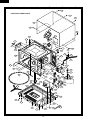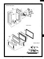
1
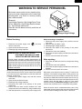
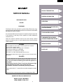
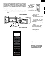
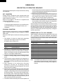
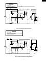
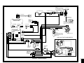
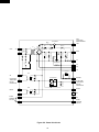
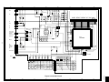
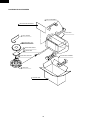
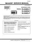
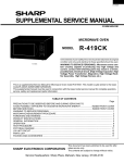
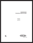
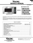
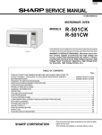
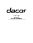
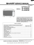
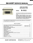
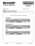
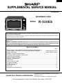
R- 530ES
SUPPLEMENTAL SERVICE MANUAL
S51M166R530EE
MICROWAVE OVEN
SENSOR COOKING
Sensor
reheat
CUSTOM
HELP
Fresh
vegetables
Rice
Baked
potatoes
Ground
meat
Poultry
Fish
Seafood
Popcorn
FROZEN FOODS
Entrees
MODEL
Snacks Vegetables
LET'S COOK
Breakfast
Defrost
Center
R-530ES
Lunch 15 Minute
Recipes
From the Beverage
Pantry
Center
1 2 3 4 5
6 7 8 9 0
Keep Warm
Plus
Power
Level
Minute
Plus
Start
Touch On
R-530ES
This is a supplemental Service Manual for Microwave Oven model R-530ES. This model is quite similar to the base models;
R-530EK/EW (S3108R530EUW/).
This supplemental manual must be used in conjunction with the base model service manual for complete operation, service,
safety and replacement parts information.
In the interest of user-safety the oven should be restored to its original condition and only parts identical to those specified
should be used.
WARNING TO SERVICE PERSONNEL: Microwave ovens contain circuitry capable of producing very high voltage and
current, contact with following parts may result in a severe, possibly fatal, electrical shock. (High Voltage Capacitor, High
Voltage Power Transformer, Magnetron, High Voltage Rectifier Assembly, High Voltage Harness etc..)
TABLE OF CONTENTS
Page
PRECAUTIONS TO BE OBSERVED BEFORE AND DURING SERVICING TO
AVOID POSSIBLE EXPOSURE TO EXCESSIVE MICROWAVE ENERGY .................... INSIDE FRONT COVER
BEFORE SERVICING ...................................................................................................... INSIDE FRONT COVER
WARNING TO SERVICE PERSONNEL ............................................................................................................... 1
MICROWAVE MEASUREMENT PROCEDURE ................................................................................................... 2
FOREWORD AND WARNING ............................................................................................................................. 3
PRODUCT SPECIFICATIONS ............................................................................................................................. 4
GENERAL INFORMATION ................................................................................................................................. 4
OPERATION ........................................................................................................................................................ 6
TOUCH CONTROL PANEL ................................................................................................................................. 8
PICTORIAL DIAGRAM ......................................................................................................................................... 9
POWER UNIT CIRCUIT ..................................................................................................................................... 10
LSI UNIT CIRCUIT ............................................................................................................................................. 11
PARTS LIST ....................................................................................................................................................... 12
PACKING AND ACCESSORIES ........................................................................................................................ 16
SHARP ELECTRONICS CORPORATION
This document has been published to be used for after
sales service only.
The contents are subject to change without notice.
Service Headquarters: Sharp Plaza, Mahwah, New Jersey, 07430-2135
R- 530ES
PRECAUTIONS TO BE OBSERVED BEFORE AND
DURING SERVICING TO AVOID POSSIBLE
EXPOSURE TO EXCESSIVE MICROWAVE
ENERGY
(a) Do not operate or allow the oven to be operated with the door open.
(b) Make the following safety checks on all ovens to be serviced before activating the magnetron or other
microwave source, and make repairs as necessary: (1) interlock operation, (2) proper door closing, (3)
seal and sealing surfaces (arcing, wear, and other damage), (4) damage to or loosening of hinges and
latches, (5) evidence of dropping or abuse.
(c) Before turning on microwave power for any service test or inspection within the microwave generating
compartments, check the magnetron, wave guide or transmission line, and cavity for proper alignment,
integrity, and connections.
(d) Any defective or misadjusted components in the interlock, monitor, door seal, and microwave
generation and transmission systems shall be repaired, replaced, or adjusted by procedures described
in this manual before the oven is released to the owner.
(e) A microwave leakage check to verify compliance with the Federal Performance Standard should be
performed on each oven prior to release to the owner.
BEFORE SERVICING
Before servicing an operative unit, perform a microwave emission check as per the Microwave
Measurement Procedure outlined in this service manual.
If microwave emissions level is in excess of the specified limit, contact SHARP ELECTRONICS
CORPORATION immediately @1-800-237-4277.
If the unit operates with the door open, service person should 1) tell the user not to operate the oven
and 2) contact SHARP ELECTRONICS CORPORATION and Food and Drug Administration's
Center for Devices and Radiological Health immediately.
Service personnel should inform SHARP ELECTRONICS CORPORATION of any certified unit found
with emissions in excess of 4mW/cm2. The owner of the unit should be instructed not to use the unit
until the oven has been brought into compliance.
R-530ES
WARNING TO SERVICE PERSONNEL
Microwave ovens contain circuitry capable of producing very high voltage and current, contact with
following parts may result in a severe, possibly
fatal, electrical shock.
(Example)
High Voltage Capacitor, High Voltage Power Transformer, Magnetron, High Voltage Rectifier Assembly, High Voltage Harness etc..
Read the Service Manual carefully and follow all
instructions.
Don't Touch !
Danger High Voltage
When the testing is completed,
1. Disconnect the power supply cord, and then remove
outer case.
2. Open the door and block it open.
3. Discharge high voltage capacitor.
4. Reconnect the leads to the primary of the power
transformer.
5. Reinstall the outer case (cabinet).
6. Reconnect the power supply cord after the outer case is
installed.
7. Run the oven and check all functions.
Before Servicing
1. Disconnect the power supply cord
remove outer case.
2. Open the door and block it open.
3. Discharge high voltage capacitor.
, and then
WARNING:RISK OF ELECTRIC SHOCK.
DISCHARGE THE HIGH-VOLTAGE
CAPACITOR BEFORE SERVICING.
After repairing
The high-voltage capacitor remains charged about 60
seconds after the oven has been switched off. Wait for 60
seconds and then short-circuit the connection of the highvoltage capacitor (that is the connecting lead of the highvoltage rectifier) against the chassis with the use of an
insulated screwdriver.
1. Reconnect all leads removed from components during
testing.
2. Reinstall the outer case (cabinet).
3. Reconnect the power supply cord after the outer case is
installed.
4. Run the oven and check all functions.
Whenever troubleshooting is performed the power supply
must be disconnected. It may, in some cases, be necessary
to connect the power supply after the outer case has been
removed, in this event,
1. Disconnect the power supply cord, and then remove
outer case.
2. Open the door and block it open.
3. Discharge high voltage capacitor.
4. Disconnect the leads to the primary of the power
transformer.
5. Ensure that the leads remain isolated from other
components and oven chassis by using insulation tape.
6. After that procedure, reconnect the power supply cord.
Microwave ovens should not be run empty. To test for the
presence of microwave energy within a cavity, place a cup
of cold water on the oven turntable, close the door and set
the power to HIGH and set the microwave timer for two (2)
minutes. When the two minutes has elapsed (timer at zero)
carefully check that the water is now hot. If the water
remains cold carry out Before Servicing procedure and reexamine the connections to the component being tested.
When all service work is completed and the oven is fully
assembled, the microwave power output should be checked
and a microwave leakage test should be carried out.
1
R-530ES
MICROWAVE MEASUREMENT PROCEDURE
A. Requirements:
1) Microwave leakage limit (Power density limit): The power density of microwave radiation emitted by a microwave oven
should not exceed 1mW/cm2 at any point 5cm or more from the external surface of the oven, measured prior to acquisition
by a purchaser, and thereafter (through the useful life of the oven), 5 mW/cm2 at any point 5cm or more from the external
surface of the oven.
2) Safety interlock switches Primary interlock relay and door sensing switch shall prevent microwave radiation emission in
excess of the requirement as above mentioned, secondary interlock switch shall prevent microwave radiation emission
in excess of 5 mW/cm2 at any point 5cm or more from the external surface of the oven.
B. Preparation for testing:
Before beginning the actual measurement of leakage, proceed as follows:
1) Make sure that the actual instrument is operating normally as specified in its instruction booklet.
Important:
Survey instruments that comply with the requirement for instrumentation as prescribed by the performance standard for
microwave ovens, 21 CFR 1030.10(c)(3)(i), must be used for testing.
2) Place the oven tray in the oven cavity.
3) Place the load of 275±15 ml (9.8 oz) of tap water initially at 20±5½C (68½F) in the center of the oven cavity.
The water container shall be a low form of 600 ml (20 oz) beaker with an inside diameter of approx. 8.5 cm (3-1/2 in.)
and made of an electrically nonconductive material such as glass or plastic.
The placing of this standard load in the oven is important not only to protect the oven, but also to insure that any leakage
is measured accurately.
4) Set the cooking control on Full Power Cooking Mode.
5) Close the door and select a cook cycle of several minutes. If the water begins to boil before the survey is completed,
replace it with 275 ml of cool water.
C. Leakage test:
Closed-door leakage test (microwave measurement)
1) Grasp the probe of the survey instrument and hold it perpendicular to the gap between the door and the body of the oven.
2) Move the probe slowly, not faster than 1 in./sec. (2.5 cm/sec.) along the gap, watching for the maximum indication on
the meter.
3) Check for leakage at the door screen, sheet metal seams and other accessible positions where the continuity of the metal
has been breached (eg., around the switches, indicator, and vents).
While testing for leakage around the door pull the door away from the front of the oven as far as is permitted by the closed
latch assembly.
4) Measure carefully at the point of highest leakage and make sure that the highest leakage is no greater than 4mW/cm2,
and that the secondary interlock switch does turn the oven OFF before any door movement.
NOTE: After servicing, record data on service invoice and microwave leakage report.
2
R-530ES
PRODUCT DESCRIPTION
SERVICE MANUAL
GENERAL INFORMATION
MICROWAVE OVEN
OPERATION
R-530ES
FOREWORD
TROUBLESHOOTING GUIDE AND
TEST PROCEDURE
This Manual has been prepared to provide Sharp Electronics Corp.
Service Personnel with Operation and Service Information for the SHARP
MICROWAVE OVEN, R-530ES.
TOUCH CONTROL PANEL
It is recommended that service personnel carefully study the entire text
of this manual so that they will be qualified to render satisfactory
customer service.
Check the interlock switches and the door seal carefully. Special
attention should be given to avoid electrical shock and microwave
radiation hazard.
COMPONENT REPLACEMENT
AND ADJUSTMENT PROCEDURE
WIRING DIAGRAM
WARNING
Never operate the oven until the following points are ensured:
(A) The door is tightly closed.
(B) The door brackets and hinges are not defective.
(C) The door packing is not damaged.
(D) The door is not deformed or warped.
(E) There is no other visible damage with the oven.
Servicing and repair work must be carried out only by trained service
personnel.
DANGER
Certain initial parts are intentionally not grounded and present
a risk of electrical shock only during servicing. Service personnel - Do not contact the following parts while the appliance is
energized;
High Voltage Capacitor, Power Transformer, Magnetron, High
Voltage Rectifier Assembly, High Voltage Harness;
If provided, Vent Hood, Fan assembly, Cooling Fan Motor.
All the parts marked “*” on parts list are used at voltages more than
250V.
Removal of the outer wrap gives access to voltage above 250V.
SHARP ELECTRONICS CORPORATION
SHARP PLAZA, MAHWAH,
NEW JERSEY 07430-2135
3
PARTS LIST
R-530ES
SPECIFICATION
ITEM
DESCRIPTION
Power Requirements
120 Volts / 13.8 Amperes
60 Hertz
Single phase, 3 wire grounded
Power Output
1200 watts (IEC TEST PROCEDURE)
Operating frequency of 2450MHz
Case Dimensions
Width
24"
Height 13-3/8"
Depth 19-1/8"
Cooking Cavity Dimensions
Width 17-3/8"
Height 10-1/2"
Depth 18-5/8"
2.0 Cubic Feet
Control Complement
Touch Control System
Clock ( 1:00 - 12:59 )
Timer (0 - 99 min. 99 seconds)
Microwave Power for Variable Cooking
Repetition Rate;
100 PERCENT.............................. Full power throughout the cooking time
90 PERCENT ............................................... approx. 90% of Full Power
80 PERCENT ............................................... approx. 80% of Full Power
70 PERCENT ............................................... approx. 70% of Full Power
60 PERCENT ............................................... approx. 60% of Full Power
50 PERCENT ............................................... approx. 50% of Full Power
40 PERCENT ............................................... approx. 40% of Full Power
30 PERCENT .............................................. approx. 30% of Full Power
20 PERCENT ............................................... approx. 20% of Full Power
10 PERCENT ............................................... approx. 10% of Full Power
0 PERCENT ................................ No power throughout the cooking time
Sensor Cooking pads, Breakfast pad, Lunch pad
15 Minute Recipes pad, Defrost center pad, From the pantry pad
Beverage center pad, Number selection pads, Timer/Clock pad
Keep Warm Plus pad, Minute plus pad, Power Level pad
Stop/Clear pad, Start/Touch On pad
Oven Cavity Light
Yes
Safety Standard
UL Listed
FCC Authorized
DHHS Rules, CFR, Title 21, Chapter 1, Subchapter J
GENERAL INFORMATION
GROUNDING INSTRUCTIONS
This oven is equipped with a three prong grounding plug. It must be plugged into a wall receptacle that is properly installed
and grounded in accordance with the National Electrical Code and local codes and ordinances. In the event of an electrical
short circuit, grounding reduces the risk of electric shock by providing an escape wire for the electric current.
WARNING: Improper use of the grounding plug can result in a risk of electric shock.
Electrical Requirements
The electrical requirements are a 120 volt 60 Hz, AC only, 15 or 20 amp. fused electrical supply. It is recommended that a
separate circuit serving only this appliance be provided. When installing this appliance, observe all applicable codes and
ordinances.
A short power-supply cord is provided to reduce risks of becoming entangled in or tripping over a longer cord.
4
R-530ES
Where a two-pronged wall-receptacle is encountered, it is the personal
responsibility and obligation of the customer to contact a qualified
electrician and have it replaced with a properly grounded three-pronged
wall receptacle or have a grounding adapter properly grounded and
polarized. If the extension cord must be used, it should be a 3-wire, 15
amp. or higher rated cord. Do not drape over a countertop or table where
it can be pulled on by children or tripped over accidentally.
CAUTION: DO NOT UNDER ANY CIRCUMSTANCES CUT OR REMOVE THE ROUND GROUNDING PRONG FROM THIS
PLUG.
OVEN DIAGRAM
5
6
7
12
9
11
8
10
2
1
4
3
TOUCH CONTROL PANEL
Grounded
Receptacle Box
3-Pronged
Plug
Grounding Pin
3-Pronged Receptacle
1. One touch door open button.
Push to open door.
2. Door latches.
The oven will not operate unless
the door is securely closed.
3. Removable turntable support.
4. Removable turntable.
The turntable will rotate
clockwise or counterclockwise.
5. Oven lamp.
It will light when oven is operating
or door is opened.
6. Oven door with see-through
window.
7. Ventilation openings. (Rear)
8. Auto-Touch control panel.
9. Time display: Digital display, 99
minutes 99 seconds.
10. Coupling.
11. Wave guide cover.
12. Power supply cord.
SENSOR COOKING
Popcorn
Sensor
reheat
CUSTOM
HELP
Fresh
vegetables
Rice
Baked
potatoes
Ground
meat
Poultry
Fish
Seafood
NOTE:
The directed features are disabled
after three minutes when the oven
is not in use. These features are
automatically enabled when the
door is opened and closed or the
STOP/ CLEAR pad is pressed.
FROZEN FOODS
Entrees
Snacks Vegetables
LET'S COOK
Breakfast
Defrost
Center
Lunch 15 Minute
Recipes
From the Beverage
Pantry
Center
1 2 3 4 5
6 7 8 9 0
Keep Warm
Plus
Power
Level
Minute
Plus
Start
Touch On
R-530ES
5
R-530ES
OPERATION
DESCRIPTION OF OPERATING SEQUENCE
the secondary interlock switch and primary interlock relay
and is mechanically associated with the door so that it will
function in the following sequence.
(1) When the door opens from the closed position, the primary
interlock relay (RY2) and secondary interlock switch open
their contacts. And contacts of the relay (RY1) remains
closed. Then the monitor switch contacts close.
(2) When the door is closed from the open position, the
monitor switch contacts open first. Then the contacts of
the secondary interlock switch and door sensing switch
close. And contacts of the relay (RY1) open.
If the secondary interlock switch and primary interlock relay
(RY2) fail with the contacts closed when the door is opened,
the closing of the monitor switch contacts will form a short
circuit through the monitor fuse, secondary interlock switch,
relay (RY1) and primary interlock relay (RY2), causing the
monitor fuse to blow.
The following is a description of component functions during
oven operation.
OFF CONDITION
Closing the door activates the door sensing switch and
secondary interlock switch. (In this condition, the monitor
switch contacts are opened.)
When oven is plugged in, 120 volts A.C. is supplied to the
control unit. (Figure O-1).
1. The display will show "Welcome".
To set any program or set the clock, you must first touch
the STOP/CLEAR pad. The display will clear, and " : "
will appear.
COOKING CONDITION
Program desired cooking time by touching the NUMBER
pads. Program the power level by touching the POWER
LEVEL pad.
When the START pad is touched, the following operations
occur:
POWER LEVEL 0% TO 100% COOKING
When Variable Cooking Power is programmed, the 120 volts
A.C. is supplied to the power transformer intermittently
through the contacts of relay (RY-2) which is operated by the
control unit within a 32 second time base. Microwave power
operation is as follows:
1. The contacts of relays are closed and components
connected to the relays are turned on as follows.
(For details, refer to Figure O-2)
RELAY
RY-1
RY-2
VARI-MODE
CONNECTED COMPONENTS
oven lamp/turntable motor/fan motor
power transformer
2. 120 volts A.C. is supplied to the primary winding of the
power transformer and is converted to about 3.2 volts A.C.
output on the filament winding, and approximately 2360
volts A.C. on the high voltage winding.
3. The filament winding voltage heats the magnetron filament
and the H.V. winding voltage is sent to a voltage doubler
circuit.
4. The microwave energy produced by the magnetron is
channelled through the waveguide into the cavity feedbox, and then into the cavity where the food is placed to
be cooked.
5. Upon completion of the cooking time, the power
transformer, oven lamp, etc. are turned off, and the
generation of microwave energy is stopped. The oven will
revert to the OFF condition.
6. When the door is opened during a cook cycle, the monitor
switch, door sensing switch, secondary interlock switch,
relay (RY1) and primary interlock relay are activated with
the following results. The circuits to the turntable motor,
the cooling fan motor, and the high voltage components
are de-energized, the oven lamp remains on, and the
digital read-out displays the time still remaining in the
cook cycle when the door was opened.
7. The monitor switch electrically monitors the operation of
OFF TIME
100% power
32 sec.
0 sec.
approx. 90% power
30 sec.
2 sec.
approx. 80% power
26 sec.
6 sec.
approx. 70% power
24 sec.
8 sec.
approx. 60% power
22 sec.
10 sec.
approx. 50% power
18 sec.
14 sec.
approx. 40% power
16 sec.
16 sec.
approx. 30% power
12 sec.
20 sec.
approx. 20% power
8 sec.
24 sec.
approx. 10% power
0% power
Note:
6
ON TIME
6 sec.
26 sec.
0 sec.
32 sec.
The ON/OFF time ratio does not correspond with the
percentage of microwave power, because approx. 2
seconds are needed for heating of the magnetron
filament.
R-530ES
SCHEMATIC
NOTE: CONDITION OF OVEN
1. DOOR CLOSED.
2. CLOCK APPEARS ON DISPLAY.
MAGNETRON
TEMP.
FUSE
NOTE:
Indicates components with potential above 250 V.
MONITOR
FUSE 20A
COM.
N.O.
CAPACITOR 1.0µF
AC 2300V
F1
AH SENSOR
(RY-2)
PRIMARY
INTERLOCK
RELAY
(RY-1)
A1
F2
F3
A2
GRN
CONTROL UNIT
N.O.
COM.
120V AC
60 Hz
B1
POWER
TRANSFORMER
B2
N.C.
DOOR
SENSING
SWITCH
CAVITY
TEMP.
FUSE
TTM
OL
OVEN
LAMP
MONITOR
SWITCH
FM
TURNTABLE
MOTOR
COM.
H.V. RECTIFIER
MAGNETRON
FAN
MOTOR
SECONDARY
INTERLOCK
SWITCH
Figure O-1. Oven Schematic-Off Condition
SCHEMATIC
NOTE: CONDITION OF OVEN
1. DOOR CLOSED.
2. COOKING TIME PROGRAMMED.
3. VARIABLE COOKING CONTROL "P-HI/ 100 PERCENT".
4. "START" PAD TOUCHED.
MAGNETRON
TEMP.
FUSE
MONITOR
FUSE 20A
COM.
N.O.
F3
A2
(RY-2)
PRIMARY
INTERLOCK
RELAY
(RY-1)
F1
A1
F2
CAPACITOR 1.0µF
AC 2300V
GRN
CONTROL UNIT
N.O.
COM.
120V AC
60 Hz
B1
CAVITY
TEMP.
FUSE
POWER
TRANSFORMER
B2
N.C.
DOOR
SENSING
SWITCH
TTM
OL
OVEN
LAMP
TURNTABLE
MOTOR
MONITOR
SWITCH
FM
COM.
H.V. RECTIFIER
MAGNETRON
FAN
MOTOR
SECONDARY
INTERLOCK
SWITCH
Figure O-2. Oven Schematic-Cooking Condition
7
R-530ES
TEST PROCEDURES
PROCEDURE
LETTER
J
COMPONENT TEST
KEY UNIT TEST
1. Disconnect the power supply cord, and then remove outer case.
2. Open the door and block it open.
3. Discharge high voltage capacitor.
4. If the display fails to clear when the STOP/CLEAR pad is depressed, first verify the flat ribbon
cable is making good contact, verify that the door sensing switch (stop switch) operates properly;
that is the contacts are closed when the door is closed and open when the door is open. If the door
sensing switch (stop switch) is good, disconnect the flat ribbon cable that connects the key unit
to the control unit and make sure the door sensing switch is closed (either close the door or short
the door sensing switch connecter). Use the Key unit matrix indicated on the control panel
schematic and place a jumper wire between the pins that correspond to the STOP/CLEAR pad
making momentary contact. If the control unit responds by clearing with a beep the key unit is
faulty and must be replaced. If the control unit does not respond, it is a faulty and must be replaced.
If a specific pad does not respond, the above method may be used (after clearing the control unit)
to determine if the control unit or key pad is at fault.
5. Reconnect all leads removed from components during testing.
6. Re-install the outer case (cabinet).
7. Reconnect the power supply cord after the outer case is installed.
8. Run the oven and check all functions.
G1
Fresh
vegetables
Ground
meat
Entrees
G2
Rice
G3
G4
G5
G6
G7
G8
Beverage
Center
1
2
3
4
5
G9
From the
Pantry
Poultry
Fish
Vegetables Seafood
6
7
8
9
0
G10
Start
Touch On
Timer
Clock
Keep
Warm
Plus
Snacks
Minute
Plus
G11
G12
G13
Breakfast
Power
Level
Lunch
Stop
Clear
15
Minute
Recipes
Defrost
Center
Custom
Help
Baked
potatoes
Sensor
reheat
Popcorn
G14
8
1
RED
RED
A
WHT
CN-F
1 BLK
2 RED
3 WHT
MAGNETRON TEMP. FUSE
WHT
B
C
D
E
F
G
H
1
CAVITY TEMP. FUSE
NOTE:
The grounding conductor of
the power supply cord has
been grounded by power
supply cord fixing screw.
The screw must always be
kept tight.
RED
H
N
WHT
AH SENSOR
GRY
POWER SUPPLY
CORD 120V 60Hz
2
2
DOOR
SENSING
SWITCH
CONTROL PANEL
N.O.
PNK
COM.
(LSI UNIT)
to Oven cavity
CN-F
CN-G
NOTE:
The neutral (WHT/GRY) wire must
be connected to the terminal with
"N" mark on the power supply
cord.
GRN
GRN
WHT
CN-C
GRN
ORG
ORG
ORG
3
3
WHT
RY2
9
BRN
1
CN-B
BLUE MARK
2 GRN
NOTE:
Hot (ORG) wire must be
connected to the terminal
with blue mark on the oven
light socket.
CN-B
1 WHT
N.O.
1
2
2
1 PNK
COM.
RED
RED
(POWER UNIT)
PRIMARY
INTERLOCK
RELAY
BLU
OVEN LAMP
AND SOCKET
CN-A
T1
CN-A
ORG
N.O.
B LU
4
HIGH VOLTAGE COMPONENTS
4
BLK
FAN MOTOR
WHT
RED
WHT
N.C.
RED
COM.
MONITOR
FUSE
&
HOLDER
TURNTABLE
MOTOR
MAGNETRON
HIGH VOLTAGE
WIRE A
5
5
MONITOR
SWITCH
BLK
BRN
WHT
SECONDARY NO
INTERLOCK
SWITCH
COM.
WHT
WHT
WHT
WHT
GRY
HIGH
VOLTAGE
CAPACITOR
RED
WHT
POWER
TRANSFORMER
H.V. RECTIFIER
6
6
A
B
C
D
E
F
G
H
R-530ES
Figure S-1. Pictorial Diagram
R-530ES
Q2 2SB1238
R4 27
C10
LED
C2
GND
C3
VC
C1
VA
C4
INT
C9
VR
C5
BUZZER
C6
OVEN LAMP
TURNTABLE
MOTOR
FAN MOTOR
C7
MICRO
C8
NC
B2
C11
NC
B2
C12
DOOR
SENSING
SWITCH
+
–
+
–
C4 10µ/35v
b
D2
C3 0.1µ/50v
D4
1SS270A
ZD1
HZ16-1
6
1SS270A
R5 4.7k
R1 2.4k
3
d
a
D1
D3
10G471K
A2
4
D6
C2 1000µ/35v
1
A1
VRS1
AC
D5
C1 0.1µ/50v
D1-D4
11ES1
T1
CN-A
CN-C
12PIN LEAD
WIRE HARNESS
R3 510 1/2w
(J1)
Q1 2SB1238
R2 680 1/2w
c
SP1 PKM22EPT
OVEN LAMP
TURNTABLE
MOTOR
FAN MOTOR
NO
Q3 KRC243M
R6 3.3k
+
–
D8
NO
COM
DOOR
SENSING
SWITCH
1SS270A
RY2
MICRO
Figure S-2. Power Unit Circuit
10
C5 10µ/35v
D7
COM
1SS270A
RY1
AC
A
B
C
D
E
F
G
H
Q30
DTA143EAK
R92 1.8kF
P22
R101
75kF
P23
R15
4.7k
(J16)
COM16
COM15
COM14
COM13
COM12
COM11
COM10
COM9
SEG40
SEG39
SEG38
SEG37
SEG36
SEG35
SEG34
SEG33
SEG32
SEG31
SEG30
SEG29
SEG28
SEG27
SEG26
SEG25
SEG24
SEG23
SEG22
SEG21
SEG20
SEG19
SEG18
SEG17
SEG16
SEG15
SEG14
SEG13
SEG12
SEG11
SEG10
SEG9
SEG8
SEG7
SEG6
SEG5
SEG4
SEG3
SEG2
SEG1
COM1
COM2
COM3
COM4
COM5
COM6
COM7
COM8
R18 R17 R16
4.7k 4.7k 4.7k
R19
4.7k
AIN3
(J17) 4.7k
(J14)
AIN2
(J15) 4.7k
(J10)
(J12)
AIN1
(J11) 4.7k
AIN0
C-11
R40
4.7k
F-2
F-3
37
Entrees
Rice
8
9
0
G10
Timer
Clock
Keep
Warm
Plus
Snacks
Minute
Plus
G11
G12
G13
Fish
Seafood
Breakfast
Power
Level
Lunch
Stop
Clear
15
Minute
Recipes
Defrost
Center
Custom
Help
Baked
potatoes
Sensor
reheat
Popcorn
R79 270k
7
R78 270k
6
R77 270k
From the
Pantry
R76 270k
G9
R75 270k
5
R74 270k
G8
4
C65 330p/50v
G7
3
C64 330p/50v
G6
2
C63 330p/50v
G5
1
C62 330p/50v
G4
C61 330p/50v
R67 15k
G3
Start
Touch On
COM8
SEG39
CF1
CST4.00MGW
P00
R66 15k
P01
R65 15k
R64 15k
R63 15k
P02
Beverage
Center
Poultry
Vegetables
P03
73
72
R68 15k P17
5
Ground
Meat
P04
R62 15k
G2
5
Fresh
vegtables
P05
C60 330p/50v
G1
R61 15k
: IF NOT SPECIFIED 1/10W ± 5%
R60 15k
NOTE
P06
108
SEG34
SEG35
SEG36
SEG37
SEG38
SEG39
SEG40
SEG41
SEG42
SEG43
SEG44
SEG45
SEG46
SEG47
SEG48
SEG49
SEG50
SEG51
SEG52
SEG53
SEG54
SEG55
SEG56
SEG57
SEG58
SEG59
SEG60
SEG61
SEG62
SEG63
SEG64
SEG65
SEG66
SEG67
COM15
COM14
IC-1
IXA098DR
CN-F
P07
COM15
SEG34
COM5
36
R41 15k
MA152WA
C40 0.01µ/25v
C-8
C-12
COM6
COM7
SEG0
SEG1
SEG2
SEG3
SEG4
SEG5
SEG6
SEG7
SEG8
SEG9
SEG10
SEG11
SEG12
SEG13
SEG14
SEG15
SEG16
SEG17
SEG18
SEG19
SEG20
SEG21
SEG22
SEG23
SEG24
SEG25
SEG26
SEG27
SEG28
SEG29
SEG30
SEG31
SEG32
SEG33
R95
15k
P24
F-1
AH SENSOR
(J13) 4.7k
C14 0.01µ/25v
Q10
2SA1037AK
R97
15k
109
4
4
NC
DOOR
SENSING
SWITCH
NC
P21
C92
0.01µ/25v
D20
11
P20
COM5
COM4
COM3
COM2
COM1
COM0
VL1
VL2
VL3
VL4
VL5
C3
C2
C1
VLIN
VREG
NC
VSS
P27
P26
P25
P24
P23
P22
P21
P20
P47
P46
P45
P44
P43
CNTR0
P41
INT0
P07
P06
C93
0.01µ/25v
R93 360kF
R100
150kF
Q21
DTA123JKA
R99
300k
R98
620k
C-7
1
P05
P04
P03
P02
P01
P00
P17
P16
P15
P14
AIN7
AIN6
AIN5
AIN4
RESET
NC
XCOUT
XCIN
NC
VCC
OSCSEL
XOUT
VSS
NC
XIN
NC
AIN3
AIN2
AIN1
AIN0
COM8
COM9
COM10
COM11
COM12
COM13
CNTRO
IC-2
BA4558
P44
MICRO
R11 15k
ZD10
UDZ4.3B
COM0
C20
0.1µ/50v
144
MA152WA
AIN5
C-5
SENSOR DEFROST TURNTABLE OFF COOK HELP
VL1
AIN4
BUZZERR
VL2
3
3
C-6
C90 0.1µ/50v
P45
OVEN LAMP
TURNTABLE
MOTOR
FAN MOTOR
R94
4.7k
R91
3.32kD
R90
330 1w
Q20
DTA143EAK
C91 0.1µ/50v
C-1
R102
37.4kF
VA
C18
0.1µ/50v
VL3
D90
8
7
6
5
C-9
1
2
3
4
VR
C17
0.1µ/50v
C16
0.1µ/50v
LD10 LD11 LD12 LD13
R96
3.57kD
C-10
LD15 LD14
LED
VL4
C15
0.1µ/50v
2
C-3
2
VC
C13 0.01µ/25v
–
R12 15k
+
C11 0.1µ/50v
C-4
C10 47µ/16v
INT
Q11
DTA143EAK
1
1
C12
0.1µ/50v
C-2
R10 1k
CN-C
GND
R69 15k P16
R70 15k P15
R71 15k P14
R72 15k AIN7
R73 15k AIN6
G14
CN-G
6
6
A
B
C
D
E
F
G
H
R-530ES
Figure S-3 LSI Unit Circuit
R-530ES
PARTS LIST
∆” may cause undue microwave exposure.
Note: The parts marked “∆
The parts marked “*” are used in voltage more than 250V. "§" MARK: PARTS DELIVERY SECTION.
REF. NO.
PART NO.
DESCRIPTION
Q'TY CODE
ELECTRIC PARTS
*
*
*∆
*
1- 1
1- 2
1- 3
1- 4
1- 5
1- 6
1- 7
1- 8
1- 9
1-10
1-11
1-12
1-13
1-14
1-15
RC-QZB018MRE0
FH-DZB008MRY0
QSOCLB006MRE0
RLMPTA068WRE0
RMOTEA346WRE0
QFSHDB003MRE0
FFS-BA016/KIT
QSW-MA085WRE0
QFS-TA013WRE0
QFS-TA014WRE0
RV-MZA293WRE0
RMOTDA211WRE0
RTRN-B066MRE0
FACCDB003MRE0
FDTCTA206WRKZ
High voltage capacitor
High voltage rectifier assembly
Oven lamp socket
Oven lamp
Fan motor
Fuse holder
Monitor switch (V-16G-2C25) and fuse assembly (20A 250V AC)
Secondary interlock switch and door sensing switch (V-5230Q)
Mgnetron temperature fuse 150½C
Cavity temperature fuse 150½C
Magnetron
Turntable motor
Power transformer
Power supply cord
AH sensor
1
1
1
1
1
1
1
2
1
1
1
1
1
1
1
AQ
AM
AE
AE
AR
AD
AF
AE
AE
AF
BE
AK
BA
AM
AW
1
4
1
BC
AB
AY
1
1
1
1
1
1
1
2
4
4
2
1
1
1
1
1
1
1
2
1
1
1
1
1
1
1
1
1
1
1
1
1
3
BL
AB
AB
AU
AA
AF
AA
AA
AB
AA
AA
AB
AA
AA
AB
AA
AA
AA
AG
AG
BC
AE
AE
AA
BC
AV
AL
AD
AF
AA
AF
AF
AA
1
1
1
1
1
1
AB
AE
AF
AD
AG
AC
CABINET PARTS
2- 1
2- 2
2- 3
GDAI-B061MRP0
GLEGPB004MRF0
GCABUB087MRP0
Base plate
Foot
Outer case cabinet
3- 1
3- 1A
3- 1B
3- 1C
C1
C2
C3
C4-5
D1-4
D5-8
Q1-2
Q3
R1
R2
R3
R4
R5
R6
RY1-2
SP1
T1
VRS1
VRS1
ZD1
3- 2
3- 3
3-3-1
3-3-2
3-3-3
3-3-4
3- 4
3- 5
3- 6
DPWBFB094MRU0
QCNCMA275DRE0
QCNCMA275DRE0
FW-VZB146MRE0
RC-KZA087DRE0
VCEAB31VW108M
RC-KZA087DRE0
VCEAB31VW106M
VHD11ES1///-1
VHD1SS270A/-1
VS2SB1238//-3
VSKRC243M//-3
VRD-B12EF242J
VRD-B12HF681J
VRD-B12HF511J
VRD-B12EF270J
VRD-B12EF472J
VRD-B12EF332J
RRLY-A113DRE0
RALM-A014DRE0
RTRNPB009MRE0
RH-VZA032DRE0
RH-VZB002MRE0
VHEHZ161///-1
DPWBFC167WRKZ
FPNLCB346MRK0
FUNTKB281MRE0
JBTN-B091MRF0
HDECAB049MRP0
MSPRTA050WRE0
LHLD-B006MRF0
PSHEPB027MRE0
XEPSD30P10XS0
Power unit
J
2-pin connector (CN-A)
J
2-pin connector (CN-B)
M
12P wire harness (CN-C)
J
Capacitor
0.1 uF
50V
J
Capacitor
1000 uF
35V
J
Capacitor
0.1 uF
50V
J
Capacitor
10 uF
35V
J
Diode (11ES1)
J
Diode (1SS270ATA)
J
Transistor (2SB1238)
J
Transistor (KRC243M)
J
Resistor
2.4k ohm
1/4W
J
Resistor
680 ohm
1/2W
J
Resistor
510 ohm
1/2W
J
Resistor
27 ohm
1/4W
J
Resistor
4.7k ohm
1/4W
J
Resistor
3.3k ohm
1/4W
M
Relay (DU24D1-1PR(M))
J
Buzzer (PKM22EPT)
M
Transformer
J
Varistor (10G471K)
M
Varistor (470ND-10D) (Interchangeable)
J
Zener diode (HZ16-1)
LSI unit
Control panel frame assembly
Key unit
Open button
Decoration plate
Open button spring
LCD holder
LED sheet
Screw; 3mm x 10mm
444444-
LBNDKB007MRP0
LANGTB049MRP0
PHOK-B018MRF0
MLEVPB016MRF0
PDUC-B104MRF0
NFANPB006MRE0
H.V. Capacitor band
Chassis support
Latch hook
Switch lever
Magnetron duct
Fan blade
CONTROL PANEL PARTS
OVEN PARTS
1
2
3
4
5
6
12
R-530ES
REF. NO.
PART NO.
DESCRIPTION
4- 7
4- 8
4- 9
4-10
4-11
4-12
4-13
PDUC-B088MRF0
------------PCOVPB085MRP0
PPACGB014MRF0
PDUC-B106MRP0
PCUSU0464MRE0
PCUSGB037MRP0
Fan duct
Oven cavity
(Not a replaceable part)
Waveguide cover
Turntable motor packing
Sensor duct
Cushion
Cushion
5- 1
5- 2
5- 3
5 -4
5- 5
5- 6
FCOV-B132MRK0
LSTPPB021MRF0
MSPRTA046WRE0
FDORFB049MRT0
PSHEPB016MRE0
GCOVHB028MRF0
Door frame [DMO2420B]
Latch head
Latch spring
Door panel [DMO2420B/S]
Sealer film
Choke cover
Q'TY CODE
1
1
1
1
1
1
1
AC
-AV
AA
AG
AC
AA
1
1
1
1
1
1
AN
AE
AB
AX
AD
1
1
1
1
1
1
1
1
1
1
1
1
AF
AU
AA
AN
AT
AA
AB
AD
AD
AC
AD
AD
5
3
1
2
11
4
2
3
2
4
AA
AA
AA
AB
AA
AA
AA
AA
AA
AA
DOOR PARTS
MISCELLANEOUS
6- 1
6- 2
6- 3
6- 4
6- 5
6- 6
6- 7
6- 8
6- 9
6-10
6-11
6-12
FW-VZB125MRE0
FW-VZB168MRE0
TLABBB007MRE0
FROLPB025MRK0
NTNT-A099WRE0
TCAUAB037MRR0
TCAUAB033MRR0
TINSEB265MRR0
QW-QZB016MRE0
TCADUB006MRR0
TLAB-B040MRR0
TLABBB008MRE0
Stop switch harness
Main wire harness
Cavity hole cover
Turntable support
Turntable tray
Monitor caution label
DHHS/Screw caution label
Operation manual
High voltage wire A
Recipe card
Menu label
UL screw caution label
7777777777-
LX-BZA041WRE0
LX-CZ0052WRE0
XHTSD40P12RV0
LX-CZA070WRE0
XOTSD40P12000
XCBSD30P08000
LX-CZA038WRE0
XHTSD40P08RV0
XOTSF40P12000
XOTSE40P12000
Special
Special
Screw :
Special
Screw :
Screw :
Special
Screw :
Screw :
Screw :
SCREWS,NUTS AND WASHERS
1
2
3
4
5
6
7
8
9
9
screw
screw
4mm x
screw
4mm x
3mm x
screw
4mm x
4mm x
4mm x
12mm
(Torx tamper proof screw)
12mm
8mm
8mm
12mm [DMO2420B/S]
12mm [DMO2420R]
13
R-530ES
2
1
4
3
6
5
7-4
A
OVEN AND CABINET PARTS
A
7-4
7-7
2-3
7-9
B
B
4-7
7-7
6-7
7-6
7-2
C
1-10
C
1-15
6-12
1-5
7-6
4-6
7-3
4-11
7-9
7-6
1-14
7-8
D
4-8
D
1-9
7-8
4-2
4-9
7-5
1-11
E
6-11
6-6
1-3
7-2
6-3
E
1-4
7-2
6-5
4-5
7-1
7-5
1-8
4-3
4-10
1-12
F
F
1-13
7-6
4-13
2-1
6-4
1-7
1-8
7-1
4-4
1-6
4-1
1-1
G
G
1-2
7-5
2-2
2-2
H
7-5
2-2
1
2
4-12
H
7-5
2-2
4
3
14
5
6
R-530ES
2
1
4
3
6
5
CONTROL PANEL PARTS
A
A
3-3
3-2
3-3-3
3-6
B
3-6
3-6
3-3-1
3-5
C
B
3-4
3-1
C
3-3-2
3-4
DOOR PARTS
D
D
5-6
5-5
E
E
5-4
5-1
F
F
MISCELLANEOUS
5-2
5-3
6-1
G
G
6-2
6-9
Actual wire harness may be different from illustration.
H
H
1
2
4
3
15
5
6
R-530ES
PACKING AND ACCESSORIES
TOP PAD ASSEMBLY
DOOR PROTECTION SHEET
PLASTIC BAG
TRAY HOLDER
6-5 TURNTABLE TRAY
6-8 OPERATION MANUAL
6-10 RECIPE CARD
6-4 TURNTABLE SUPPORT
IN
TO
E
TH
OV
EN
CA
VIT
Y
BOTTOM PAD ASSEMBLY
TRAY PACK
PACKING CASE
16
R-530ES
Notes
17
R-530ES
COPYRIGHT © 2001 BY SHARP CORPORATION
ALL RIGHTS RESERVED.
No part of this publication may be reproduced,
stored in retrieval systems, or transmitted in
any form or by any means, electronic, mechanical, photocopying, recording, or otherwise, without prior written permission of the
publisher.
'01 SHARP CORP. (5M2.60E) Printed in U.S.A
18