1
Angus Evo Multi Fuel Boiler
Installation, Operation and Maintenance Manual
Index
Information on the boiler plate
........................................................................................................1
Boiler dimensions, boiler packaging dimensions . . . . . . . . . . . . . . . . . . . . . . . . . . . . . . . . . . . . . . . . . . . . . . . . . . . . . . . . . . . . . . . . . . . . . . . . . . . . . . . . . . . . . . 2
Technical parameters
..................................................................................................................3
A table of the Angus Evo Heating Area . . . . . . . . . . . . . . . . . . . . . . . . . . . . . . . . . . . . . . . . . . . . . . . . . . . . . . . . . . . . . . . . . . . . . . . . . . . . . . . . . . . . . . . . . . . . . . . . 4
Introduction
............................................................................................................................5
Ensuring safety of equipment and people
Head loses
.............................................................................................5
.............................................................................................................................6
Operating Instructions
Angus Evo Series Boiler – general features . . . . . . . . . . . . . . . . . . . . . . . . . . . . . . . . . . . . . . . . . . . . . . . . . . . . . . . . . . . . . . . . . . . . . . . . . . . . . . . . . . . . . . . . . . . . 6
Recommended fuel . . . . . . . . . . . . . . . . . . . . . . . . . . . . . . . . . . . . . . . . . . . . . . . . . . . . . . . . . . . . . . . . . . . . . . . . . . . . . . . . . . . . . . . . . . . . . . . . . . . . . . . . . . . . . . . . . . . . . 6
Control and safety devices
Temperature safety valve
.............................................................................................................7
...............................................................................................................8
Hydraulic connection diagram . . . . . . . . . . . . . . . . . . . . . . . . . . . . . . . . . . . . . . . . . . . . . . . . . . . . . . . . . . . . . . . . . . . . . . . . . . . . . . . . . . . . . . . . . . . . . . . . . . . . . . . . . 9
Putting the boiler into service
. . . . . . . . . . . . . . . . . . . . . . . . . . . . . . . . . . . . . . . . . . . . . . . . . . . . . . . . . . . . . . . . . . . . . . . . . . . . . . . . . . . . . . . . . . . . . . . . . . . . . . . . . 13
Checking the boiler before turning it on
Filling and draining the heating system
Operation and controls
Starting a fire
. . . . . . . . . . . . . . . . . . . . . . . . . . . . . . . . . . . . . . . . . . . . . . . . . . . . . . . . . . . . . . . . . . . . . . . . . . . . . . . . . . . . . . . . . . . . . . 13
. . . . . . . . . . . . . . . . . . . . . . . . . . . . . . . . . . . . . . . . . . . . . . . . . . . . . . . . . . . . . . . . . . . . . . . . . . . . . . . . . . . . . . . . . . . . . . . . . . . . . . . . . . . . . . 13
. . . . . . . . . . . . . . . . . . . . . . . . . . . . . . . . . . . . . . . . . . . . . . . . . . . . . . . . . . . . . . . . . . . . . . . . . . . . . . . . . . . . . . . . . . . . . . . . . . . . . . . . . . . . . . . . . . . . . . . . . 13
Setting outlet water temperature
Stoking
. . . . . . . . . . . . . . . . . . . . . . . . . . . . . . . . . . . . . . . . . . . . . . . . . . . . . . . . . . . . . . . . . . . . . . . . . . . . . . . . . . . . . . . . . . . . . 13
. . . . . . . . . . . . . . . . . . . . . . . . . . . . . . . . . . . . . . . . . . . . . . . . . . . . . . . . . . . . . . . . . . . . . . . . . . . . . . . . . . . . . . . . . . . . . . . . . . . . . 13
. . . . . . . . . . . . . . . . . . . . . . . . . . . . . . . . . . . . . . . . . . . . . . . . . . . . . . . . . . . . . . . . . . . . . . . . . . . . . . . . . . . . . . . . . . . . . . . . . . . . . . . . . . . . . . . . . . . . . . . . . . . . . . . . 14
Overnight heating mode
. . . . . . . . . . . . . . . . . . . . . . . . . . . . . . . . . . . . . . . . . . . . . . . . . . . . . . . . . . . . . . . . . . . . . . . . . . . . . . . . . . . . . . . . . . . . . . . . . . . . . . . . . . . . . 14
Removing solid combustion residuals
Dewing and tarring
. . . . . . . . . . . . . . . . . . . . . . . . . . . . . . . . . . . . . . . . . . . . . . . . . . . . . . . . . . . . . . . . . . . . . . . . . . . . . . . . . . . . . . . . . . . . . . . . 14
. . . . . . . . . . . . . . . . . . . . . . . . . . . . . . . . . . . . . . . . . . . . . . . . . . . . . . . . . . . . . . . . . . . . . . . . . . . . . . . . . . . . . . . . . . . . . . . . . . . . . . . . . . . . . . . . . . . 14
Boiler shutdown . . . . . . . . . . . . . . . . . . . . . . . . . . . . . . . . . . . . . . . . . . . . . . . . . . . . . . . . . . . . . . . . . . . . . . . . . . . . . . . . . . . . . . . . . . . . . . . . . . . . . . . . . . . . . . . . . . . . . . . 14
Short term shutdown . . . . . . . . . . . . . . . . . . . . . . . . . . . . . . . . . . . . . . . . . . . . . . . . . . . . . . . . . . . . . . . . . . . . . . . . . . . . . . . . . . . . . . . . . . . . . . . . . . . . . . . . . . . . . . . . . . 14
Long term shutdown
. . . . . . . . . . . . . . . . . . . . . . . . . . . . . . . . . . . . . . . . . . . . . . . . . . . . . . . . . . . . . . . . . . . . . . . . . . . . . . . . . . . . . . . . . . . . . . . . . . . . . . . . . . . . . . . . . . 14
Important information
. . . . . . . . . . . . . . . . . . . . . . . . . . . . . . . . . . . . . . . . . . . . . . . . . . . . . . . . . . . . . . . . . . . . . . . . . . . . . . . . . . . . . . . . . . . . . . . . . . . . . . . . . . . . . . . . 14
Boiler cleaning . . . . . . . . . . . . . . . . . . . . . . . . . . . . . . . . . . . . . . . . . . . . . . . . . . . . . . . . . . . . . . . . . . . . . . . . . . . . . . . . . . . . . . . . . . . . . . . . . . . . . . . . . . . . . . . . . . . . . . . . 15
Boiler repairs . . . . . . . . . . . . . . . . . . . . . . . . . . . . . . . . . . . . . . . . . . . . . . . . . . . . . . . . . . . . . . . . . . . . . . . . . . . . . . . . . . . . . . . . . . . . . . . . . . . . . . . . . . . . . . . . . . . . . . . . . . 17
Warranty and warranty conditions
. . . . . . . . . . . . . . . . . . . . . . . . . . . . . . . . . . . . . . . . . . . . . . . . . . . . . . . . . . . . . . . . . . . . . . . . . . . . . . . . . . . . . . . . . . . . . . . . . . . 17
Boiler delivery . . . . . . . . . . . . . . . . . . . . . . . . . . . . . . . . . . . . . . . . . . . . . . . . . . . . . . . . . . . . . . . . . . . . . . . . . . . . . . . . . . . . . . . . . . . . . . . . . . . . . . . . . . . . . . . . . . . . . . . . . 17
Installation Instructions
Boiler installation – general information
Heating water requirements
Boiler location
. . . . . . . . . . . . . . . . . . . . . . . . . . . . . . . . . . . . . . . . . . . . . . . . . . . . . . . . . . . . . . . . . . . . . . . . . . . . . . . . . . . . . . . . . . . . . 18
. . . . . . . . . . . . . . . . . . . . . . . . . . . . . . . . . . . . . . . . . . . . . . . . . . . . . . . . . . . . . . . . . . . . . . . . . . . . . . . . . . . . . . . . . . . . . . . . . . . . . . . . . . 18
. . . . . . . . . . . . . . . . . . . . . . . . . . . . . . . . . . . . . . . . . . . . . . . . . . . . . . . . . . . . . . . . . . . . . . . . . . . . . . . . . . . . . . . . . . . . . . . . . . . . . . . . . . . . . . . . . . . . . . . . 19
Minimum distances
. . . . . . . . . . . . . . . . . . . . . . . . . . . . . . . . . . . . . . . . . . . . . . . . . . . . . . . . . . . . . . . . . . . . . . . . . . . . . . . . . . . . . . . . . . . . . . . . . . . . . . . . . . . . . . . . . . . 19
Boiler room disposition layout . . . . . . . . . . . . . . . . . . . . . . . . . . . . . . . . . . . . . . . . . . . . . . . . . . . . . . . . . . . . . . . . . . . . . . . . . . . . . . . . . . . . . . . . . . . . . . . . . . . . . . . . 20
Installation procedure
. . . . . . . . . . . . . . . . . . . . . . . . . . . . . . . . . . . . . . . . . . . . . . . . . . . . . . . . . . . . . . . . . . . . . . . . . . . . . . . . . . . . . . . . . . . . . . . . . . . . . . . . . . . . . . . . 20
Angus Evo boiler parts . . . . . . . . . . . . . . . . . . . . . . . . . . . . . . . . . . . . . . . . . . . . . . . . . . . . . . . . . . . . . . . . . . . . . . . . . . . . . . . . . . . . . . . . . . . . . . . . . . . . . . . . . . . . . . . . 21
Spare parts list
. . . . . . . . . . . . . . . . . . . . . . . . . . . . . . . . . . . . . . . . . . . . . . . . . . . . . . . . . . . . . . . . . . . . . . . . . . . . . . . . . . . . . . . . . . . . . . . . . . . . . . . . . . . . . . . . . . . . . . . . 22
Accumulator tank capacity
. . . . . . . . . . . . . . . . . . . . . . . . . . . . . . . . . . . . . . . . . . . . . . . . . . . . . . . . . . . . . . . . . . . . . . . . . . . . . . . . . . . . . . . . . . . . . . . . . . . . . . . . . . . 23
Transportation and storage . . . . . . . . . . . . . . . . . . . . . . . . . . . . . . . . . . . . . . . . . . . . . . . . . . . . . . . . . . . . . . . . . . . . . . . . . . . . . . . . . . . . . . . . . . . . . . . . . . . . . . . . . . . 23
Flue pipe installation
. . . . . . . . . . . . . . . . . . . . . . . . . . . . . . . . . . . . . . . . . . . . . . . . . . . . . . . . . . . . . . . . . . . . . . . . . . . . . . . . . . . . . . . . . . . . . . . . . . . . . . . . . . . . . . . . . 24
Chimney and chimney connection warnings . . . . . . . . . . . . . . . . . . . . . . . . . . . . . . . . . . . . . . . . . . . . . . . . . . . . . . . . . . . . . . . . . . . . . . . . . . . . . . . . . . . . . . . . . 24
Troubleshooting . . . . . . . . . . . . . . . . . . . . . . . . . . . . . . . . . . . . . . . . . . . . . . . . . . . . . . . . . . . . . . . . . . . . . . . . . . . . . . . . . . . . . . . . . . . . . . . . . . . . . . . . . . . . . . . . . . . . . . . 25
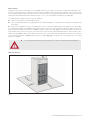
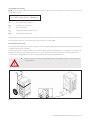
Information on the boiler plate
The boiler Serial No. is shown on the plate which is attached to the cover panel of the cast iron body.
fig.01
INSTALLATION, OPERATION AND MAINTENANCE MANUAL 1
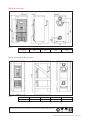
Boiler dimensions
fig.02
L (mm)
EV-03
EV-04
EV-05
EV-06
609
709
809
909
EV-03
EV-04
EV-05
EV-06
665
765
865
965
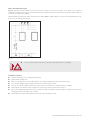
Boiler packaging dimensions
fig.03
L (mm)
Notice: Please obey to the meanings of the symbols on packaging for health care
INSTALLATION, OPERATION AND MAINTENANCE MANUAL 2
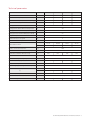
Technical parameters
Series Name
EV-03
EV-04
EV-05
EV-06
Number of Elements
Pcs.
3
4
5
6
Nominal Heat Output (Black Coal – Walnut)
kW
15-17
24-27
31-34
38-41
Nominal Heat Output (Hardwood – Split Logs) kW
12-14
18-20
25-27
30-33
9.2
12.1
14.6
18.5
Minimum Heat Output
kW
Heating Water Maximum Temperature
˚C
90
Heating Return Water Minimum Temperature
˚C
50
Burning Time for Nominal Output (B. Coal)
hr
>4
Burning Time for Nominal Output (H. Wood)
hr
>2
Range of Temperature Control
˚C
30-90
Maximum Pressure of System
bar
4
Minimum Pressure of System
bar
0.4
Boiler Water Content
L
m3
16.33
20.30
24.27
28.24
0.01633
0.0203
0.02427
0.02824
Exit Flue Connection Diameter
mm
180
Combustion Chamber Dimensions (WxH)
mm
300 x 380
Combustion Chamber Dimensions (L)
mm
Water Inlet-Outlet Connection
(")
G1 1/2"
Inlet-Outlet Safety Cooling Loop Connection
(")
G 3/8"
Minimum Chimney Depression
mbar
Safety Value Temperature Limit
˚C
95
Boiler Category (according to EN 303-5)
Class
1
Boiler Dimensions (WxH)
mm
(L)
mm
245
0.12
345
0.14
445
545
0.17
0.20
809
909
237
267
450 x 947
609
709
Exit Flue Gas Temperature
˚C
190-260
Maximum Noise Level acc. to Valid Norms
dB
45-60 (A)
Boiler Net Weight
kg
177
207
INSTALLATION, OPERATION AND MAINTENANCE MANUAL 3
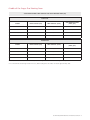
A table of the Angus Evo Heating Area
SOLID FUEL BOILERS HEAT OUTPUT AND MAX HEATING AREA (M2)
FOR COAL
MODEL
HEAT OUTPUT (kW)
HEAT OUTPUT (kCAL)
MAX HEATING AREA
(UNC) (M2)
Solid Fuel – 03
17
14,617
146
Solid Fuel – 04
27
23,216
232
Solid Fuel – 05
34
29,235
292
Solid Fuel – 06
41
35,254
353
FOR WOOD
MODEL
HEAT OUTPUT (kW)
HEAT OUTPUT (kCAL)
MAX HEATING AREA
(UNC) (M2)
Solid Fuel – 03
14
12,038
120
Solid Fuel – 04
20
17,197
172
Solid Fuel – 05
27
23,216
232
Solid Fuel – 06
33
28,375
284
*** For cold climate and low insulation houses, Max Heating Area should be decreased approximately 10%
*** For mild climate and strong insulation houses, Max Heating Area should be increased approximately 10%
INSTALLATION, OPERATION AND MAINTENANCE MANUAL 4
Introduction
1.
The boiler and all associated equipment must be installed and used in accordance with the installation design, all applicable
legal regulations and technical standards and with the manufacturer’s instructions. The boiler may be used only for the purpose
for which it is intended.
2.
The boiler may be installed only in an environment which it is designed for.If the boiler is delivered to the client by the same
person who installs it, he must give the user also all accompanying boiler documentation (in particular User Guide, Service Book,
etc.). Until the boiler is put into service, the original packaging must be kept in case the boiler has to be transported again.
3.
After installation, the boiler must be put into operation by a service organisation authorised by the manufacturer.
4.
The boiler complies with regulations applicable in the European Union. When used in the conditions of countries outside at
EU, any deviations from local regulations must be identified and rectified.
5.
In the event of a defect, call an authorised manufacturer’s service organisation–any unauthorised interference may damage
the boiler (and possibly also associated equipment!).
6.
The service technician putting the boiler into operation for the first time must show the user the various parts of the boiler and
how to control the boiler, with the boiler safety elements, their signals and appropriate user reaction to them, with fundamental
parts of the boiler and their controls. If the boiler is delivered to the client by the same person who installs it,he must make
sure that the original packaging is available in case the boiler has to be transported again.
7.
Check the delivery for completeness.
8.
Check whether the model and type supplied is suitable for the required use.
9.
Whenever you are not certain how to control the boiler, study appropriate instructions in this Operation and Installation Guide
carefully and proceed accordingly.
10. Never remove or damage any markings and signs on the boiler. Keep the original packaging until the boiler has been put
into service, in case the boiler has to be transported again.
11. When making any repairs, only original parts must always be used. It is forbidden to make any changes to the boiler’s internal
installation, or to interfere with it in any way.
12. At the end of its life cycle, the boiler its package and its parts must be disposed of in a way avoiding harm to the environment.
13. The manufacturer disclaims any responsibility for damages caused by the failure to abide by:
■
■
■
■
The conditions stipulated in this Operation and Installation Guide;
Applicable regulations and standards;
Sound installation and operation procedures; and
Conditions stated in the Warranty Certificate and the Service Book.
Situations might occur in practice, when the following essential precautions must be taken:
■
■
■
Shut the boiler down every time when there are any (even temporary) flammable or explosive fumes present on the premises
from which combustion air is supplied to the boiler (e.g. from paint when painting, laying and spraying molten substances,
from gas leakage, etc.);
If it is necessary to drain water from the boiler or from the whole system, the water must not be dangerously hot; and
If there is any leakage from the boiler’s heat exchanger, or when the exchanger is clogged up with ice, do not attempt to
start up the boiler until normal operating conditions have been restored.
Ensuring safety of equipment and people
■
■
■
■
The boiler (and all accessories) complies with the requirements of EN 303-5 its updates and all relevant European standards.
In order to run and operate the boiler in accordance with the purpose for which it is designed in actual conditions of use
(hereafter referred to only as use), it is necessary to abide also by additional requirements the most essential ones of which
(i.e. those which must not be omitted) are found in the related regulatory documents.
In addition to the above mentioned documents, it is necessary when using the boiler to proceed in accordance with this
Operation and Installation guide and the accompanying boiler manufacturer’s documentation.
Any interference by children, persons under the influence of narcotic drugs, certified persons, etc., when using the boiler, must
be prevented.
INSTALLATION, OPERATION AND MAINTENANCE MANUAL 5
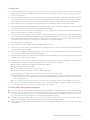
Head loses
fig.04
Operating instructions
Angus Evo Series Boiler – general features
■
■
■
■
■
■
■
■
Angus Evo Series solid fuel fired boiler is designed for heating both residential and industrial buildings.
Besides professional installation, precondition for correct functioning of the boiler is the required chimney thrust and
correct operation.
Angus Evo Series solid fuel fired boiler is designed for heating systems which are suitable for forced circulation systems only.
Angus Evo Series boilers are available in four output series (determined by the number of segments 3, 4, 5, 6) from 17 to 41 kW.
The cast iron boiler body comprises of segments and serves as a combustion chamber (including combustion gases routes),
and at the same time as a water reservoir (including water routes). Segments are of three types – front and rear, inserted
between which are 1 to 8 middle segments (of the same kind). By assembling and joining together an appropriate number of
segments, a boiler body of the required size is constructed (both the combustion chamber and the water reservoir). Assembled
boiler body is equipped with necessary pipe sections for water connection. It also has brackets for fitting thermostat sensors
and brackets on feet for fastening the boiler to the base. Attached to the cast iron boiler body are sheet metal covers which
are fitted on the inside with thermal insulation.
To ensure that the boiler functions correctly and runs economically, it is important that its nominal output is equal to the thermal
losses of the heated premises.
Choosing a boiler of insufficient output will result in inadequate heating of the premises, and thus failure to provide a
heating comfort.
Choosing a boiler of unnecessarily high output will result in the boiler not running in full output, and as a consequence in
tarring and dewing.
Recommended fuel
■
■
■
■
■
■
Recommended fuels for Angus Evo boilers are coal, coke and firewood.
Optimal coal and coke granularity is 24-60mm.
Optimal firewood size is logs of diameter 40-100mm. Their length will depend on how many segments the boiler have.
Fuel must be stored in a dry place. To reach the boiler nominal output, water content in firewood must not exceed 20%.
Approximate stoking intervals (referred to as Burning Time) are shown in the Technical Data Table on page 3.
The boiler is stoked manually.
Please note
The boiler is not intended for burning any type of waste.
INSTALLATION, OPERATION AND MAINTENANCE MANUAL 6
Control and safety devices
Angus Evo boilers are equipped with three main control elements:
A chimney flap (Fig. 05), by means of which the chimney thrust can be controlled, i.e. the discharge of combustion fumes into
the chimney. The flap is situated in the flue neck of the boiler, and is controlled manually.
Chimney flap
fig.05
Another thrust control element is a thermo-mechanical output regulator (Fig. 06). It is situated on the outlet from the boiler
cast iron body. It detects temperature of the hot water and regulates the supply of primary combustion air to underneath the boiler
stoker, by opening or shutting a flap situated in the ashtray door.
Thermo-mechanical regulator
1. Regulation head
2. Arm holder
3. Arm
4. Regulator body
5. Hexagon
6. Pit
fig.06
■
■
■
When fitting the safety and the control elements remember to meet the principles of work safety.
If replacing of safety device and of thermo-mechanical output regulator is necessary, please use
recommended devices in case of using any other type of the device negotiate with Eco Angus Ltd.
Functionality of thermo-mechanical output regulator (satrom) must be checked or inspected by
authorised person once in a year.
Changing the hatch position controls the combustion intensity and thus the boiler output. The thermo mechanical output regulator is
connected with the regulating hatch by chain. The chain is connected to the hatch in such a way that its tension can be set (Fig. 07).
Regulation hatch
Keep object’s away from regulation hatch’s front
and channels for allowing primary air transfer.
fig.07
INSTALLATION, OPERATION AND MAINTENANCE MANUAL 7
Supply of secondary combustion air is controlled by an air rosette (Fig. 08), situated in the boiler’s stoking door, which has a direct
effect on the level of emission.
Hot water temperature can be checked on a thermometer (Fig. 09), which is situated in the front boiler cover above the stoking door.
Air rosette
fig.08
Thermometer
fig.09
Temperature safety valve
The Angus Evo boilers can be equipped with a safety heat exchanger with thermal safety valve as an optional which ensures
dissipation of excessive heat without additional device and supply of external energy in such a way that the maximum permissible
boiler temperature of 95°C is not exceeded.
For more information on the safety heat exchanger with thermal safety valve please see http://www.ecoangus.co.uk/
ecoangus_images/Test_Reports_and_Instruction%20Manuals/1958_Safety_Heat_Exchanger_Manual_FINAL.pdf
INSTALLATION, OPERATION AND MAINTENANCE MANUAL 8
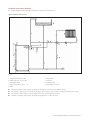
Hydraulic connection diagram
It is suggested hydraulic system should be installed according to following schemes.
Open expansion tank system
fig. 10
1. Safety Heat Exchanger (SHT)
2. Safety Valve (TS 131, STS 20)
3. Cold Water Feed
4. System Safety Valve (3 bar – 1/2")
5. NRV
■
■
■
■
6. Mixing Valve
7. CH Pump
8. Heating System
9. Open Expansion Tank
Open-type expansion tank must be equipped with the highest level in the entire hydraulic system.
The expansion tank must be selected properly against the changes in water volume resulting from heating and cooling.
The expansion tanks and their connecting pipes must be protected against to freezing.
Diameter of drainage pipe must be selected properly against to overflow into tank.
INSTALLATION, OPERATION AND MAINTENANCE MANUAL 9
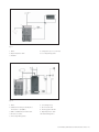
fig. 11
1. Boiler
2. Open Expansion Tank
3. Radiator
4. Safety Valve (TS 131, STS 20)
5. Four Way Mixing Valve
fig. 12
1. Boiler
2. Laddomat 21-60 operated by Flue
Thermostat – 50-300°C
3. NAD or NADO Accumulator Tank
4. Immersion Heater
5. Three Way Mixing Valve
6. Circulating Pump
7. Room Thermostat
8. Heating System Outlet
9. Open Expansion Tank
10. DHW Mixing Valve
INSTALLATION, OPERATION AND MAINTENANCE MANUAL 10
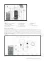
fig. 13
1. Boiler
2. Laddomat 21-60 operated by Flue
Thermostat – 50-300°C
3. NAD or NADO Accumulator Tank
4. Immersion Heater
5. Three Way Mixing Valve
6. Circulating pump
7. Room Thermostat
8. Heating System Outlet
9. Open Expansion Tank
10. DHW Mixing Valve
11. Solar Coil
12. Solar
13. Solar Circulation Pump
Systems for Pressurised Tank
In a pressurized system consideration should be given for an appropriately sized expansion vessel on the central heating circuit
before the return to the boiler and a safety group on the primary flow. It is essential to ensure that the expansion vessel is sized
accordingly to your system. It is recommended to use an expansion vessel that is 15% of the volume of water in your system including
the primary water in the accumulator tank if applicable. An appropriately rated pressure relief valve should also be used in the
safety group. It is also recommended to use a safety heat exchanger with a thermal safety valve that we offer to ensure the boiler
has overheat protection installed.
fig. 14
INSTALLATION, OPERATION AND MAINTENANCE MANUAL 11
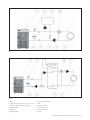
fig. 15
fig. 16
1. Boiler
2. Safety Group (automatic air vent, pressure
reducing valve and pressure gauge)
3. DHW Cylinder
4. CH Pump
5. Heating System
6. Four Way Mixing Valve
7. NRV
8. Expansion Vessel
9. Accumulator Tank
10. Three Way Valve
11. Valve
INSTALLATION, OPERATION AND MAINTENANCE MANUAL 12
Putting the boiler into service
Checking the boiler before turning it on
Before putting the boiler into operation, the service technician must check:
■
■
■
■
Whether the installation conforms with the design;
Whether the boiler has been filled in and is under pressure (on the thermo-manometer), and whether there are any leakage
in the heating system;
Connection to the chimney – connection must be approved by an authorised chimney sweep (chimney inspection);
Functioning of the heating controls.
Please note
The service technician must show the user how to control the boiler and enter the date when the boiler was put into service into the
Warranty Certificate.
Filling up and draining the heating system
The system can only been filled up or topped up with water which meets the parameters specified by EN standards. The water must
be clear, colourless, free of suspended particles, oil and chemically corrosive substances, and must not be acidic (pH factor must
be greater than 7.2). First of all, the heating system must be thoroughly flushed and all dirt washed out.
Please note
Water in system must not be reduced or put out unless the boilers is in service or under freezing danger.
Against freezing anti-freeze liquid can be added in to system water at the rate of 15%.
The failure to meet this requirement may lead to the heat exchanger getting clogged up, and the cast iron block may crack as a result.
During the heating season, a constant volume of water must be maintained inside the heating system. When topping up water,
care must be taken that no air is sucked into the system. Water must never be let out of the boiler or the heating system, unless it
is absolutely essential, such as before repairs, etc. Draining water and refilling the system with new water increases the risk of
corrosion and formation of incrustation.
Filling or topping up water to the heating system must always be done with the boiler cold or cooled down; otherwise the boiler
segments may crack!
Operation and controls
Starting a fire
Check on the thermo-manometer whether there is enough water in the heating system. Open the shutting valve between the boiler
and the heating system. Spread paper on top of the clean stoker and then enough finely chopped wood. Open the flue flap in the
chimney adapter and shut the stoking door. Light the paper through the open ashtray door and fully open the regulating flap in the
ashtray door. The fire has caught up enough, stoke a layer of main fuel on top of the burning firewood. When the fire is powerful
enough, stoke more fuel right up to the bottom edge of the stoking door and level it into.
Provide an even layer throughout the entire boiler depth. If the fuel suddenly turns into dark red blaze, open partially the secondary air
supply rosette in the stoking door. When the flame turns yellow, shut the secondary air supply rosette again. When the boiler has reached
the required output, it is suitable to partially shut the flue thrust flap to prevent heat from unnecessarily escaping into the chimney.
■
■
■
Do not start the boiler without connecting the boiler to the chimney.
Control chimney connections before starting the boiler.
Adjust the chimney blow as requested level. If chimney blow is under mentioned levels try not to
use the boiler.
Setting the outlet water temperature
When the required outlet water temperature is say 60°C, heat up the boiler to a temperature for instance 5°C higher than the
required temperature of 60°C (measured on the thermometer on the boiler outlet pipe). Then turn the control knob to 65°C and
check whether the chain is stretched and the regulating hatch completely shut. This position of the chain and regulating hatch is
fine-adjusted by turning the control knob.Then let the regulation process work. When the water temperature drops, the regulating
hatch will start opening by the tension applied by the regulator on the chain. When the water temperature suddenly rises, the
regulating hatch will start opening. And the hot water temperature on the boiler outlet is controlled.
INSTALLATION, OPERATION AND MAINTENANCE MANUAL 13
Stoking
First shut the regulating hatch; this will shut supply of combustion air into the boiler. Then open the chimney flap completely. Partially
open the stoking door and wait until all combustion gases have been sucked from the combustion chamber into the chimney. Only
then open the stoking door completely and start stoking the boiler. After shutting the stoking door, set the chimney flap again and
restore the functioning of the regulating hatch.
■
■
Boiler doors must not be held open as the boiler is continously working.
Provide a minimum 5 cm gap to be between top point of the fuel and ceiling of stoking chamber
when boiler is stoked.
Overnight heating mode
This mode is used when you want to maintain the fire in the boiler for instance over night. First scrape all ash out of the combustion
chamber, with the chimney flap completely opened. Then stoke the boiler with fuel and shut the boiler up completely. Then shut the
chimney flap and also almost shut the regulating hatch. This will reduce the chimney thrust and restrict the supply of combustion
air.Shut also the secondary air supply rosette in the stoking door. To restore the boiler’s required output, just open the chimney flap
and partially open the regulating hatch to the required boiler output.
Removing solid combustion residuals
This is done by removing and emptying the ashtray situated underneath the stoker in the ash compartment. This must be done
on a regular basis to prevent ash from accumulating and blocking the supply of air to the combustion chamber from underneath
the stoker.
Dewing and tarring
When starting fire in a cold boiler, water condensates on the walls and runs down into the ash compartment, which may make an
impression that the boiler is leaking. This dewing will disappear after the astray has settled on the boilers inside walls. When running
the boiler with low water temperature usually below 65°C, or when using damp fuel, water condensates in combustion gases and
the condensate runs down the boiler’s cold walls. Low temperature heating also reduces the chimney life. Therefore it is
recommended to equip the boiler with for instance a four-way blending valve which will ensure that the temperature of return water
does not drop below 50°C. Boiler tarring occurs under similar conditions (lack of combustion air, the boiler is choking). To prevent
dewing and tarring, we recommend you run the boiler at temperatures higher than 65°C and choose a boiler to match the required
heating system output. An oversized boiler suffers unnecessarily, because it has to be run at low temperatures.
Boiler shutdown
We do not recommend that you try to speed up the boiler combustion process.The fuel must burn completely on its own on
the stoker.
Short term shutdown
After shutting the boiler down, clean it, remove all combustion residuals,empty the ashtray, clean the stoking door contact surfaces
and the ash compartment, and then shut the boiler’s stoking door and ash compartment door.
Long term shutdown
When shutting the boiler down for a protracted period of time (heating season end), the boiler must be thoroughly cleaned from
all soot and ash sediments in which dampness accumulates and causes excessive corrosion of the boiler body.
Important information
■
■
■
■
■
The boiler may only be operated by an adult person familiar with these Operating Instructions.
Shut the boiler down every time there are any (even temporary) flammable or explosive fumes present on the premises from
which combustion air is supplied to the boiler (e.g. From paint when painting, laying and spraying molten substances, from
gas leakage, etc.).
It is forbidden to light the boiler with explosive substances.
It is forbidden to overheat the boiler.
At the end of the heating season the boiler, flue and flue adapter, must be thoroughly cleaned. Lubricate all hinges, the flue
flap mechanism and other moving.
INSTALLATION, OPERATION AND MAINTENANCE MANUAL 14
Boiler cleaning
When the boiler is used, soot and fine ash accumulates on the boiler walls, mainly on heat exchanger ribs and in the flue neck,
which reduces heat transfer and the boiler output. The actual quantity of soot and fine ash will depend on the quality of the fuel
used and on the boiler operating conditions.
If the boiler is oversized or was for some reason run at low temperatures, more soot is generated. This may also result in inadequate
chimney thrust.
The boiler must be cleaned regularly, at least once a month, which is done with a steel brush through an open boiler door.
After taking front section plate off, all boiler walls inside the combustion chamber and combustion gases routes should be cleaned.
If a larger quantity of tar has accumulated on internal walls of the combustion chamber, it must be removed with a scraper or burnt
with hard wood (or coke), running the boiler at maximum operating temperature.
Please note
Ashes should be stored (by using proper glove) in a non-combustible container properly and transported outdoors. Other waste
must not be stored in this container.
fig.17
fig.18
INSTALLATION, OPERATION AND MAINTENANCE MANUAL 15
fig.19
fig.20
fig.21
fig.22
INSTALLATION, OPERATION AND MAINTENANCE MANUAL 16
Boiler repairs
The boiler may be repaired by an authorised service technician or organisation only. The user or owner may do only normal
maintenance and simple replacements of some parts – e.g. sealing cords.
Please note
When repairing the boiler, original parts must always be used.
Warranty and warranty conditions
Angus Evo boilers are covered by warranty specified in the Warranty Certificate, Service Book and User and Installation Guide
(chapter Introduction, Installing the boiler).
Boiler delivery
Angus Evo boilers are delivered completely assembled and functionally tested.
The delivery includes:
1. Boiler
2. Operating and installation instructions
3. Service book
4. List of service centres
5. Warranty certificate
6. Thermo-mechanical output regulator
7. Cleaning kit (brush, mixing rod)
INSTALLATION, OPERATION AND MAINTENANCE MANUAL 17
Installation Instructions
Boiler installation – general information
Angus Evo boilers must be put into service by an authorised services. A network of authorised service organisations which meet
these conditions is available for all boiler installations, putting them into service and for warranty repairs.
The boiler is designed to supply heating systems with gauge pressure up to 400 kPa which use water that meets the requirements
of related standards (under no circumstances may the water be acidic, i.e. it must have pH>7, and it should have minimum
carbon hardness).
The heating system must be designed in such a way that hot water can circulate all the time through at least some of the radiators.
Antifreeze fluids – because of their unsuitable properties, we do not recommend to use them.They have a reduced ability to transfer
heat, have large volumetric expansion, age and damage rubber components. If under concrete circumstances there is no other
option how to reliable prevent.
Before final installation, the heating system distribution piping must be flushed several times with pressurised water. In old,already
used systems,the flushing must be done in opposite direction to the hot water circulation. In new systems, all radiators must be
cleaned from conservation material. and rinsed with warm water under pressure.
We recommend installing a sludge trap upstream of the boiler (i.e. on hot water return pipe). The sludge trap design should allow
emptying in regular intervals, without the need to drain a lot of hot water. The sludge trap may be combined with a filter; however,
a filter alone will not provide an adequate protection.
Please note
System must be connected to open expansion tank for safety reasons.
Any valve must not be connected to safety input and safety output lines.
For increasing safety of the system, by-pass line must be installed on the line between input and output of circulation pumps, as
shown in diagrams.
By-Pass line’s valve must be kept closed as the boiler is working normally.
By-Pass line’s valve can be used in electricity problems and must be opened if there is a risk of overheating in system water caused
by an electricity cut or problem.
The pipe used in by-pass line must be at least in the diameter of plumbing systems pipe.
UPS (Power Supply Units) can be used for preventing electricity problems.
Any problems (malfunctions) caused by boiler clogging with dirt from the heating system and/or malfunctions induced by clogging,
are not covered by the boiler warranty.
The filter as well as the sludge trap must be checked and cleaned regularly.
Heating water requirements
Heating water requirements are specified in EN Standards. When the sum of concentrations of calcium and magnesium in the
water exceeds 1.8mmol/l, additional non-chemical treatments preventing lime deposition must be considered (e.g. magnetic or
electrostatic field treatment).
INSTALLATION, OPERATION AND MAINTENANCE MANUAL 18
Boiler location
Angus Evo boilers can be located both on non-habitable premises (e.g. in boiler room, cellar, corridor) and in habitable rooms.
The room in which the boiler is located must have a permanent supply of air necessary for the combustion process. The air must
be free of halogen hydrocarbons and corrosive vapours, and must not be excessively humid and dusty. The room must be protected
against frost, with ambient temperature within the range +5°C to +35°C and relative humidity not exceeding 80%.
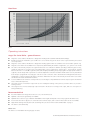
To comply with fire regulations, the boiler must be installed:
On floor constructed of non-flammable material.
On a non-flammable material overlapping the boiler footprint by 20mm on each side and covering the entire depth of the
boiler body.
■
If the boiler is installed in a cellar, we recommend to put it on a socket at least 50mm high, positioning the boiler in the middle.
To comply with standards, at least 600mm manipulation space must be left in front of the boiler. Minimum distance between the
back of the boiler and the wall must be also 600mm, and a free space of at least 600mm must be left between one side of the
boiler and the wall, to allow access to the rear of the boiler. Fuel must not be stacked directly behind on next to the boiler at a
distance less than 800mm. If there are two boilers in the boiler room, no fuel is allowed to be stacked between them. We recommend
to keep a minimum distance of 800mm between the boiler and fuel (Fig. 23), or keep fuel in a room other than the one in which
the boiler is installed.
■
■
■
Do not put flammable materials on top of the boiler or near the boiler than specified safety distance.
Minimum distances
fig.23
INSTALLATION, OPERATION AND MAINTENANCE MANUAL 19
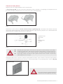
Boiler room disposition layout
Fig. 24 illustrates minimum distances which must be kept in order to ensure safe operation of the boiler room and allow
manipulations with the boiler, such as cleaning and stoking. The distance between the front of the boiler and the wall should be at
least the boiler length L plus 500mm.
Minimum distances between the boiler side and rear should be 800mm, with the distance of the rear also determined by the way
the boiler is connected to the chimney.
fig.24
■
Do not touch hot water connections or the flue outlet when the boiler is operating.
Installation procedure
■
■
■
■
■
■
■
■
Place the boiler body on a non-flammable materials.
Install a thermal safety valve.
After connecting the boiler to the heating system, screw filling and drain stopcocks into the back section.
Screw the flue adapter with smoke flap onto the boiler combustion gases outlet.
Put a flue over the flue adapter and insert it into the chimney connection hole. The flue diameter is 150mm
Install a thermo-mechanical output regulator into the opening in the top part of the front section.
We recommend fitting shutting valves on the hot water inlet and outlet, without which it would be necessary to drain the entire
heating system before the filter can be cleaned.
No shutting valve may be installed between the boiler and the expansion vessel.
INSTALLATION, OPERATION AND MAINTENANCE MANUAL 20
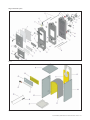
Angus Evo boiler parts
fig.25
fig.26
INSTALLATION, OPERATION AND MAINTENANCE MANUAL 21
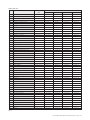
Spare parts list
ITEM
DESCRIPTION
DRAWING
PART NUMBER
NO
EV-03
EV-04
EV-05
EV-06
EV 20080100
EV-MD.060
EV-MD.060
EV-MD.060
EV-MD.060
1
Front Section
2
Middle Section
EV 20080101
EV-MD.050
EV-MD.050
EV-MD.050
EV-MD.050
3
Back Section
EV 20080102
EV-MD.070
EV-MD.070
EV-MD.070
EV-MD.070
4
Stoking Door
EV 20080103
EV-PD.010
EV-PD.010
EV-PD.010
EV-PD.010
5
Stoking Door Isolation Rope
EV 20080104
EV-CY.011
EV-CY.011
EV-CY.011
EV-CY.011
6
Stoking Door Isolation
EV 20080105
EV-SE.012
EV-SE.012
EV-SE.012
EV-SE.012
7
Stoking Door Isolation Cover
EV 20080106
EV-ST.013
EV-ST.013
EV-ST.013
EV-ST.013
8
Door Handle
EV 20080107
EV-BD.014
EV-BD.014
EV-BD.014
EV-BD.014
EV-PD.015
9
Air Rosette
EV 20080108
EV-PD.015
EV-PD.015
EV-PD.015
10
Ashtray Door
EV 20080109
EV-PD.020
EV-PD.020
EV-PD.020
EV-PD.020
11
Ashtray Door Isolation Rope
EV 20080110
EV-CY.021
EV-CY.021
EV-CY.021
EV-CY.021
12
Ashtray Door Isolation
EV 20080111
EV-SE.022
EV-SE.022
EV-SE.022
EV-SE.022
13
Ashtray Door Isolation Cover
EV 20080112
EV-ST.023
EV-ST.023
EV-ST.023
EV-ST.023
14
Grid
EV 20080113
EV-PD.030
EV-PD.030
EV-PD.030
EV-PD.030
15
Gris Lock Hinge
EV 20080114
EV-PD.031
EV-PD.031
EV-PD.031
EV-PD.031
16
Lock Hinge (24)
EV 20080115
EV-ST.090
EV-ST.090
EV-ST.090
EV-ST.090
17
Door Lock Cylinder
EV 20080116
EV-ST.041
EV-ST.041
EV-ST.041
EV-ST.041
18
Stopper 1 1/4"
EV 20080117
EV-SD.080
EV-SD.080
EV-SD.080
EV-SD.080
19
Regulation Hatch
EV 20080118
EV-PD.024
EV-PD.024
EV-PD.024
EV-PD.024
20
Regulation Hatch Isolation Rope
EV 20080119
EV-CY.025
EV-CY.025
EV-CY.025
EV-CY.025
21
Front Section Cleaning Plate
EV 20080120
EV-ST.200
EV-ST.200
EV-ST.200
EV-ST.200
22
Nipple
EV 20080121
EV-ST.110
EV-ST.110
EV-ST.110
EV-ST.110
23
Connection Rod
EV 20080122
EV-ST.123
EV-ST.124
EV-ST.125
EV-ST.126
24
Thermostat Bulb
EV 20080123
EV-PM.140
EV-PM.140
EV-PM.140
EV-PM.140
25
Thermostat Bulb Segment
EV 20080124
EV-ST.141
EV-ST.141
EV-ST.141
EV-ST.141
26
Stopper 3/4"
EV 20080125
EV-PM.131
EV-PM.131
EV-PM.131
EV-PM.131
27
Thermostatic Regulator
EV 20080126
EV-IM.150
EV-IM.150
EV-IM.150
EV-IM.150
28
Flange Gasket
EV 20080127
EV-KC.300
EV-KC.300
EV-KC.300
EV-KC.300
29
Water Inlet-Outlet Flange
EV 20080128
EV-PD.215
EV-PD.215
EV-PD.215
EV-PD.215
30
Chimney Adapter
EV 20080129
EV-PD.450
EV-PD.450
EV-PD.450
EV-PD.450
31
Chimney Flap
EV 20080130
EV-PD.405
EV-PD.405
EV-PD.405
EV-PD.405
32
Chimney Adapter Isolation Rope
EV 20080131
EV-CY.451
EV-CY.451
EV-CY.451
EV-CY.451
33
Chimney Cleaning Door
EV 20080132
EV-PD.402
EV-PD.402
EV-PD.402
EV-PD.402
34
Chimney Cleaning Door Isolation Rope
EV 20080133
EV-CY.403
EV-CY.403
EV-CY.403
EV-CY.403
35
Stopper 1/2"
EV 20080134
EV-SD.085
EV-SD.085
EV-SD.085
EV-SD.085
36
Chimney Isolation Rope
EV 20080148
EV-CY.503
EV-CY.503
EV-CY.503
EV-CY.503
37
Chimney
EV 20080149
EV-PD.500
EV-PD.500
EV-PD.500
EV-PD.500
38
Middle Section Cover
EV 20080150
EV-GS.503
EV-GS.504
EV-GS.505
EV-GS.506
39
Right Side Cover Panel
EV 20080135
EV-ST.603
EV-ST.604
EV-ST.605
EV-ST.606
40
Left Side Cover Panel
EV 20080136
EV-ST.653
EV-ST.654
EV-ST.655
EV-ST.656
41
Top Cover Panel
EV 20080137
EV-ST.703
EV-ST.704
EV-ST.705
EV-ST.706
42
Front Cover Panel
EV 20080138
EV-ST.753
EV-ST.753
EV-ST.753
EV-ST.753
43
Protection Steel Sheet
EV 20080139
EV-ST.773
EV-ST.773
EV-ST.773
EV-ST.773
44
Front Cover Panel Isolation
EV 20080140
EV-CY.763
EV-CY.763
EV-CY.763
EV-CY.763
45
Thermometer
EV 20080141
EV-IM.160
EV-IM.160
EV-IM.160
EV-IM.160
46
Rear Cover Panel
EV 20080142
EV-ST.900
EV-ST.900
EV-ST.900
EV-ST.900
47
Rear Cover Panel Isolation
EV 20080143
EV-CY.901
EV-CY.901
EV-CY.901
EV-CY.901
48
Casting Body Insulation
EV 20080144
EV-CY.553
EV-CY.554
EV-CY.555
EV-CY.556
49
Mixed Rod
EV 20080145
EV-ST.903
EV-ST.904
EV-ST.905
EV-ST.906
50
Cleaning Brush
EV 20080146
EV-ST.803
EV-ST.804
EV-ST.805
EV-ST.806
51
Ashtray
EV 20080147
EV-ST.503
EV-ST.504
EV-ST.505
EV-ST.506
fig.27
INSTALLATION, OPERATION AND MAINTENANCE MANUAL 22
Accumulator tank capacity
NOTE: The heat can be supplied for example by an accumulator tank. The following applies as a reference for the minimum
storage boiler content:
Vsp = 15Tb x QN (1-0,3 x (QH/Qmin))
Vsp
:
Accumulator tank capacity in L
QN
:
Nominal heat output in kW
Tb
:
Burning period in h
QH
:
Heating load of the premises in kW
Qmin
:
Minimum heat output in kW
Heating boilers using several allowable fuels should have the tank size based on the fuel which requires the largest accumulator tank.
The accumulator tank is not necessary when the required volume is less than 300L.
Transportation and storage
The manufacturer handles the boiler that is on a palette and secured against shifting (with screws).The boiler may not be transported
in a different position than on its base.
At least regular storage conditions shall be ensured during boiler storage and transportation (non-aggressive environment, air
humidity lower than 75%, temperature range from 5°C to 55°C, low dustiness and preventing influence of biological factors).
The force may not be applied on the boiler coverings and panel during storage and transportation.
■
Boiler must not be carried or transported without using forklifts, pallets or other wheeled
carrying vehicles.
fig.28
INSTALLATION, OPERATION AND MAINTENANCE MANUAL 23
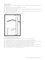
Flue pipe Installation
Fig. 29 shows the proper flue gas connection with additional air equipment. Observe the following during the installation of the
flue gas connection:
■
■
■
■
■
■
Install a flue pipe connection with an inspection aperture for cleaning.
Fasten the flue gas connector piece to the boiler.
Feed the connector into the flue gas system on a short, ascending path. Avoid deflections, especially those with an angle of 90°.
Fasten and support connectors sufficiently.
Since the flue pipe is only fixed into the flue gas system and push-fitted onto the boiler flue socket, it should be fitted very
carefully so that it does not come loose.
Only use parts of non-flammable materials for the flue gas system.
fig.29
Chimneys and chimney connection warnings
A sufficient flue draft of the flue gas system is the basic requirement for the correct functioning of the boiler.
It fundamentally affects its performance and efficiency. Therefore, heed the following for the flue gas connection:
■
■
■
■
■
■
■
Please note that the boiler must be connected to the flue gas system in accordance with the latest recommendations form Hetas.
Building code regulations, manufacture’s instructions and in consultation with an approved flue installer.
The boiler may only be connected to a flue gas system with proper flue draft (technical spec. table).
The dimension calculations of the flue gas path must be based on the flue gas mass-flow rate at maximum rated output.
The effective chimney flue height is measured from the point of entry of the flue pipe into the chimney.
Ensure that the calculation of the flue gas path and the connection of the flue gas system is only carried out by qualified personnel.
If a wrong boiler chimney is connected, the warranty is not valid.
INSTALLATION, OPERATION AND MAINTENANCE MANUAL 24
The figures below are only guide figures. The draft depends on the diameter, height, roughness of the chimney wall, and the
temperature difference between combustion products and the outside atmosphere. We recommend the use of a chimney liner.
Have precise calculations carried out by a heating engineer or flue installer.
F = a.QN
√H
Coefficient = 0,041 (for wood)
Coefficient = 0,027 (for carbon)
F
= Section Resulting (cm2)
a
= Coefficient
QN
= Boiler Heat Output (kCal/h)
H
= Height of Chimney (meters)
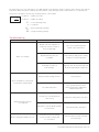
Troubleshooting
Problem
Boiler is not heating
Reason
Solution
Quality of the fuel might be low
and/or the moisture content of
the fuel maybe high
Try to use fuel which has better
calorific value and moisture
Operational instructions are
not fulfilled
Inspect chimney draft, position of flap,
circulation of outlet temperature
Tar existing on surface of
heat exchanger
Regularly clean the heat exchanger with
the brush supplied by Eco Angus Ltd
Using fuel which has high moisture
Use proper fuel
Low outlet temperature
Try to operate the boiler with a
chimney temperature 160K above
ambient temperature
Lower door is not sealed properly
when closed
Replace the sealing of the lower door
Temperature controller (draft regulator)
is not functional
Check functionality of the device
Circulation pump is not working
or water circulation was blocked
(i.e. closed valve)
Check circulation system, especially
the water pump
Over condensation on boiler part
and formation of black liquid
Outlet temperature of boiler
is not adjusted
Boiler is heating but radiators are not
INSTALLATION, OPERATION AND MAINTENANCE MANUAL 25
For more information
please visit our website
www.ecoangus.co.uk
01934 862642
07739 174511
07970 901273
[email protected]
2068. Designed and produced by