1
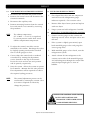
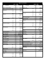
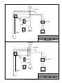
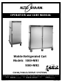
®
OPERATION and CAR E MAN UAL
Mobile Refrigerated Cart
Models: 1000-MR1
1000-MR2
COOK/HOLD/SERVE SYSTEMS
W 1 6 4 N 9 2 2 1 Wa t e r S t r e e t
PHONE:
PRINTED IN U.S.A.
●
P. O . B o x 4 5 0
262.251.3800
800.558.8744 U.S.A./CANADA
●
Menomonee Falls , Wisconsin 53052-0450
FAX: 262.251.7067 • 800.329.8744 U.S.A. ONLY
262.251.1907 INTERNATIONAL
U.S.A.
WEBSITE:
www.alto-shaam.com
#8410/11 • 3/2001
Alto-Shaam Mobile Refrigerated Carts
1.0
1.1
INTRODUCTION
This technical manual provides information
on the installation, operation, maintenance,
and inspection of this unit. A complete parts
breakdown is provided.
EQUIPMENT DESCRIPTION
The unit consists of the following:
Storage Compartment: The insulated food
storage compartment is clear storage area.
Included in this area are the adjustable
shelves and cooling coil.
Doors: Access to the storage compartment is
through a hinged-mounted insulated door.
Condensing Unit Compartment: This area
contains the condensing unit along with the
necessary controls.
Evaporator Coil: The evaporator coil is
located in the storage compartment and is
responsible for distributing the cold air
associated with the refrigeration system.
Cabinet: The cabinet is the enclosure in
which all of the above items are housed.
1.2
2.0 FUNCTIONAL DESCRIPTION
This unit is a self-contained, automatically
controlled, continuous duty perishable food
storage system. It is designed with the intent
and purpose of storing cold food items. The
operating temperature is automatically
monitored by controls that are factory-set to
maintain a predetermined, adequate
condition.
The unit consists of two basic compartment
assemblies:
a. Condensing Unit Compartment which
includes the condensing unit, the electrical
control panel with power switch and
terminal box, and a heated condensation
evaporator.
b. Storage Compartment which consists of the
insulated clear storage area for perishable
food items requiring a temperature range
of 37° to 40°F (3° to 4°C). The clear
storage area includes adjustable shelving.
2.1
EQUIPMENT SUPPLIED
The unit is shipped from the factory fully
assembled except the adjustable shelving that
will require positioning on the side racks.
The complete assembly is palletized and
crated to reduce the possibility of damage in
shipping and storage.
1.3
LEADING PARTICULARS
The refrigeration system is a closed loop
system. Unless the system develops a leak,
adding additional refrigerant is not necessary.
3.0
Refrigerant: 134a
1000-MR2
115VAC
60 Hz, 1ø
8.7 Amps
115VAC
60 Hz, 1ø
10.8 Amps
5-15P
15A, 125V Plug
NEMA
220-240VAC
50 Hz, 1ø
4.4 Amps
6-15P
15A, 250V Plug
NEMA
5-15P
15A, 125V Plug
3.1
6-15P
15A, 250V Plug
NEMA
Weight:
Net
Shipping
410 lb (186 kg)
671 lb (304kg)
To energize the system, it is only necessary to
locate the power supply cord and connect it to a
proper electrical supply source. Once the
supply cord has been connected to a power
source, the unit can be started by switching the
power control switch to the “ON” position.
NEMA
220-240VA
50 Hz, 1ø
6.3 Amps
START-UP PROCEDURE
The refrigeration system is completely factoryassembled, precharged and ready for operation.
The control has been set to display temperature
in degrees Fahrenheit or degrees Celsius as
specified on the original order.
Electrical:
1000-MR1
SYSTEM OPERATION
The primary focus for the design of the
refrigerated cabinet is for the safe storage of
food products which require refrigeration.
Considerable engineering attention was
placed on the qualities of function and
serviceability.
800 lb (363kg)
1210 lb (549kg)
SHUT-DOWN PROCEDURE
To shut-down, place the power control in the
"OFF" position and open the door to allow the
cabinet interior temperature to equalize with
the room temperature.
Use a mild detergent diluted in warm water to
wash the interior and exterior surfaces of the
cabinet.
Operation and Care Manual #8410/11 • 1
PROCEDURES
START-UP PROCEDURE
CONTROLS AND INDICATORS
TYPE
Thermostat
Contact Points
Cycles the refrigeration
system (automatic)
Suction Valve
Service Valve
Isolate suction at the
compressor.
Discharge Valve
Service Valve
Isolate discharge at
the receiver.
Power Control Switch
(ON/OFF)
Contact Points
Terminates power to
the unit.
LCD Display
Indicates continuous
cabinet temperature.
R E S U LT S
Activate system by inserting
electrical service cord into electrical
supply source. Turn power switch to
the “ON” position.
The compressor should immediately
come on-line and the condenser fan
and evaporator fan activate.
With the door closed and the
storage area empty of product, wait
for a period of 1 hour.
OUTSIDE DIMENSIONS
FULL
PERIMETER
BUMPER
PUSH
HANDLE
24-1/4" (617mm)
length
56-5/8" (1438mm)
36-1/2" (927mm)
39-1/4" (997mm)
53" (1346mm)
21-1/4"
(540mm)
Ensure the
available
power
source
matches the
voltage
stamped on
unit
nameplate.
The temperature in the storage area
will begin to decrease.
Cabinet will have reached the
proper operating temperature of
36°F ±3°F (2°C, ±1°C).
Verify correct operating
temperature.
Begin stocking the containment
area when the proper operating
temperature has been reached.
EXTENDED PERIOD OF INACTIVITY
This unit is designed for continued use at
automatically cycled intervals. In case of an
extended shut-down, the food storage
compartment must be cleaned and wiped dry to
minimize the potential of odor build-up during
shutdown.
27-1/2"
(699mm)
27-1/2"
(699mm)
FULL
PERIMETER
BUMPER
1000-MR2
WITH BUMPER
67-1/2" (1714mm)
64-1/2" (1638mm)
1000-MR1
POWER
2°
on l
C
off o
29-1/2" (749mm)
POWER
2°
on l
C
68" (1727mm)
1-3/8" (35mm)
1-3/8" (35mm)
off o
29-1/2" (749mm)
Operation and Care Manual #8410/11 • 2
54-1/4" (1378mm)
1-1/2" (35mm)
WITH BUMPER
26-1/2" (673mm)
68" (1727mm)
3.3
O P E R AT I O N
FUNCTION
24-1/2" (622mm)
29-3/4" (749mm)
NAME
O P E R AT I O N / C L E A N I N G
4.0
OPERATING PROCEDURES
5.1
CLEANING
The purpose of this mobile refrigerator is to
Follow appropriate state
maintain cold foods at proper serving
and local health (hygiene)
temperatures. The unit should be used for
regulations regarding all
the intended purpose only.
applicable cleaning and
a.
Adjust the position of the shelves to
sanitation requirements
accommodate required storage needs.
for food service equipment.
b.
Switch the power to the “ON” position.
DAILY:
c.
Prechill the cabinet to the full, factory
preset temperature of 36°F ±3°F (2°C).
d.
Load the refrigerator with chilled foods
only. Before loading, use a food
thermometer to make certain all products
are at a temperature of 41°F (5°C)
maximum or less. Cover foods to reduce
moisture build-up on the inside wall of
the cabinet. To maintain the proper
refrigerated food temperature, open the
door only when necessary. The mobile
refrigerator door may be locked if
Wipe all spills at once.
WEEKLY:
a. Remove the wire shelves and side-rack
shelf supports. Clean these items
separately using a mild, non-abrasive
detergent and soft cloth.
b. With a mild, non-abrasive detergent and
water, use a soft cloth to wipe the interior
liner of the storage compartment. Begin
at the top and work down. Wipe the
gasket surrounding the storage
compartment opening.
required.
c. Using a mild detergent and water, wipe
SWITCH UNIT POWER “OFF” AND
DISCONNECT THE POWER SUPPLY
CORD BEFORE CLEANING,
SERVICING, OR PERFORMING
SCHEDULED MAINTENANCE.
the vinyl door gasket. Make certain to
wipe under the gasket to remove any
mildew or residue.
d. Wipe interior surfaces with a clean cloth
and sanitizing solution for use on metal
5.0
CLEANING and MAINTENANCE
and vinyl food contact surfaces. This is
A thorough, periodic maintenance schedule is
required to ensure the longest and most
trouble free operation. Maintenance
schedules should be aimed at maximizing the
efficient use of maintenance personnel,
reducing down-time, and providing the
orderly acquisition of spare parts support.
an important step to control the build-up
of unwanted mildew and mold on the
evaporator coil and fan.
e. Vacuum right, left and back panel grill
vents to maintain maximum air flow.
e. Wipe the exterior of the unit with a mild
detergent and water. Always wipe with
the grain of the stainless steel to prevent
scratching the finish.
Operation and Care Manual #8410/11 • 3
SC H E DU LE D MAI NTE NANC E
6.0
MAINTENANCE
3.
The thermostat is located behind the back
wall in the upper left corner of the unit and
is clearly marked for adjustment purposes.
To adjust the temperature, turn the
thermostat counter-clockwise one or two
increments for colder operation. Turn the
thermostat clockwise one or two increments
for warmer operation. To avoid an unsafe
temperature or freezing, make small
adjustments only.
4.
Replace back wall, side rack and wire
shelves. Close the cabinet door and allow
the unit to operate without interruption for
a period of one hour.
5.
At the end of one hour, check the
temperature in the display. Repeat
adjustment as necessary.
Remember to de-energize the unit by
switching the toggle switch located on the
control panel to the “OFF” position.
Disconnect the unit from the power source.
6.1
MONTHLY INSPECTION & SERVICE
CHECK THE INLET AND OUTLET ENDS OF
THE DRAIN LINE to make certain there are
no obstructions. If an obstruction is found:
Use compressed air to unblock an obstructed
drain line in a forced air evaporator model.
Remove the drain line at the evaporator coil
and attach an air line using 60 pounds of
pressure. The use of chemicals to clear a
clogged drain is not recommended.
6.2
6.4
YEARLY INSPECTION & SERVICE
1.
INSPECT THE DOOR GASKET for cracks,
splits, and dryness.
2.
INSPECT THE MOVING PARTS OF THE
DOOR LATCH assembly for signs of wear.
Check the screw tightness on both latch
and strike.
3.
6.3
CHECK THE HINGES by opening the
door to a 90-degree angle to the cabinet.
With minimum pressure, lift up on the
outer edge of the door. Replace the hinges
if there is an upward movement of 1/2-inch
(12,7mm) or more.
1.
Disconnect all electrical power to the unit.
2.
Remove the ventilation grill. Lift the grill
vertically 1-inch (25mm) while pulling out on
the bottom and lowering the grill from the
retainer angles.
3.
Remove the mounting bolts on the
condensing unit base and slide the
refrigeration assembly out.
4.
Remove the protective shroud from around
the motor.
5.
Remove the mounting screws at the motor
base.
6.
Using an allen wrench, loosen the set screw
on the blade hub and slide blade from the
shaft.
7.
Install the new condenser fan by reversing
the process.
8.
Install the motor by reversing the process.
THERMOSTAT ADJUSTMENT
Before making any adjustment to the
thermostat, check the door gasket for proper
seal. Proper adjustment can be tested by
pulling a dollar bill through the gasket seal
and feeling a slight resistance. If it is
determined a proper seal is maintained
around the full perimeter of the gasket, a
thermostat adjustment may be necessary.
1.
Remove all shelves and remove the left-hand
side rack.
2.
Remove the interior back wall of the unit by
lifting up and out.
CONDENSER FAN & MOTOR REPLACEMENT
Operation and Care Manual #8410/11 • 4
SC H E DU LE D MAI NTE NANC E
6.6
DOOR HANDLE REPLACEMENT
NOTE:
1. Using a screwdriver, remove the three screws
It may be necessary to remove the
which attach the butt section of the hinges to
handle assembly in order to get the
the cabinet.
cabinet through a door opening.
2. With the door detached from the cabinet,
1. Remove the three side mounting screws in latch.
remove the screws which attach the second
part of the hinge to the door.
2. Remove two screws in strike.
3. To install the replacement hinge, reverse the
3. Replace in reverse order.
6.7
process.
DOOR GASKET REPLACEMENT
NOTE:
6.8
It is suggested that the door be
POWER SWITCH REPLACEMENT
1. Disconnect the unit from the power source.
removed from the cabinet and placed
2. Remove the silicone seal around the
face down on a work table.
perimeter of the front control leader panel.
1. Remove the fasteners and pull old gasket
Remove the panel by lifting straight up.
from the retainer.
3. Using a flat blade screwdriver, remove the
2. Clean gasket retainer and immediate area.
3. Start new gasket into retainer. After gasket
is positioned, replace fasteners.
NOTE: Avoid cutting the gasket if possible.
cover plate with switch attached.
4. Remove the wires connected to the switch.
5. Unscrew the lock washer and remove the
switch.
6.8
6. Reverse the process to install the new
DOOR HINGE REPLACEMENT
NOTE:
switch.
This procedure will require two people.
One person to hold the door while the
7. Remount panel and reseal with silicone.
other removes the attachment screws.
SWITCH THE CONTROL PANEL POWER
TO THE "OFF" POSITION AND
DISCONNECT THE POWER SUPPLY
CORD BEFORE SERVICING.
Operation and Care Manual #8410/11 • 5
C O R R E C T I V E M A I N T E N A N C E T R O U B L E S H O OT I N G G U I D E
SYMPTOM
Unit does not cool.
Unit does not operate.
Unit runs continuously.
Low head pressure.
High head pressure.
Short cycling.
P O S S I B L E FA I L U R E
R E M E DY
Blown fuse.
Replace fuse.
Bad connection at supply cord.
Check supply cord at outlet.
Ill-fitting gasket.
Tighten strike on door latch.
Low refrigerant.
Check system for leaks and recharge.
Control failure.
Adjust control or replace.
Blown fuse.
Replace fuse.
Incorrect voltage.
Correct.
Bad connection at supply cord.
Replace or repair.
Failed compressor.
Replace.
Low on refrigerant.
Leak-check system and recharge.
Control failure.
Adjust control or replace.
Bad TXV bulb contact.
Check and secure TXV bulb to suction line.
Restricted air flow or dirty condenser coil.
Rectify air flow problem and clean condenser.
Bad condenser fan motor.
Check and replace if necessary.
Expansion valve stuck open.
Replace.
Compressor failure.
Replace.
Ineffective door seal.
Adjust door strike.
Air circulation in storage restricted.
Redistribute food for even air flow.
Defective compressor.
Replace.
Low refrigerant.
Leak-check system and recharge.
Ambient temperature too low.
Raise room temperature.
Blocked or dirty condenser.
Clean and remove any obstructions.
Ambient temperature too high.
Improve room temperature.
System contains air.
Evacuate, change the filter dryer and recharge.
Refrigerant overcharge.
Reduce refrigerant in the system.
Maladjusted control.
Adjust control.
This char t is provided for the assistance of qualified technicians only and is not intended for
use by untrained or unauthorized ser vice personnel.
SWITCH THE CONTROL PANEL POWER
TO THE "OFF" POSITION AND
DISCONNECT THE POWER SUPPLY
CORD BEFORE SERVICING.
Operation and Care Manual #8410/11 • 6
S E RVIC E
The components addressed in the section
are considered acceptable for repair
using standard procedures. The skill
level required to perform these
repairs vary. Some require specific
training and are not intended for use by
untrained or unauthorized service personnel.
Procedures requiring refrigerant
handling require certification.
If your unit is not operating properly contact
Alto-Shaam ® for the nearest authorized service
agent. These are the only service agents the
company will authorize to repair Alto-Shaam ®
units. Repairs made by any other service agents
without prior authorization by Alto-Shaam ® will
void the warranty on the unit.
7.0
FEDERAL LAWS REQUIRE
PROPER HANDLING AND
DISPOSAL OF REFRIGERANT.
IT IS UNLAWFUL TO VENT ANY
REFRIGERANT INTO THE ATMOSPHERE
Alto-Shaam, Inc. urges all individuals
responsible for training, teaching or
advising installation mechanics and service
personnel to emphasize proper handling
and charging techniques and strict
adherence to limiting refrigerant charge
amount to those specifically recommended
by the manufacturers of refrigeration, air
conditioning or heat-pump systems.
REFRIGERANT LEAK
before opening the system valves. Front
seat the liquid or high-pressure receiver
valve to the maximum extent to prevent
refrigerant from exiting the receiver. Start
the unit and allow it to operate until the
suction or low pressure gauge indicates 5
pounds. When 5 pounds is indicated, close
the suction valve, de-energize the system
and repair the leak(s).
With the unit in a cooling cycle, use a
flashlight to locate the liquid refrigerant sight
glass. If the compressor has been operating
for three minutes, no visible bubbles should
appear within the sight glass. If bubbles
appear in the sight glass, it will be necessary
to determine if there is a refrigerant leak.
1. Make certain the unit is switched off and
the power cord is disconnected. Using a
halide or electronic leak detector, check all
fittings and connections for a leak.
2. If a leak is found on a flared fitting, it can
often be repaired by tightening the brass
flare nut a quarter of a turn. If this does
not resolve the problem, it may be
necessary to reflare the tubing.
3. If a leak is found on a brazed joint, it will
be necessary to pump-down the system
refrigerant charge to repair the leak(s).
Connect service gauges to the system at the
suction valve ( ON THE COMPRESSOR ) and liquid
valve ( ON THE RECEIVER ) to pump the
refrigerant into the receiver. To avoid
contamination, purge the gauges
7.1
EXPANSION VALVE REPLACEMENT
1. Shut liquid valve and run compressor until
it pumps refrigerant into receiver (low-side
service gauge will read 0 pounds). Close
the suction line valve.
2. Disconnect the sensor bulb on the suction
line.
3. Disconnect the 3/8" (9,5mm) liquid line
along with the 5/8" (16mm) suction line.
Remove valve.
4. Install new valve. Reconnect lines and
refasten sensor bulb.
NOTE:
The super-heat valve is preset at the
factory, therefore, adjustment is NOT
recommended.
SWITCH THE CONTROL PANEL POWER
TO THE "OFF" POSITION AND
DISCONNECT THE POWER SUPPLY
CORD BEFORE SERVICING.
Operation and Care Manual #8410/11 • 7
S E RVIC E
7.2
LOW PRESSURE CONTROL REPLACEMENT
1.
Disconnect the unit from the power source.
2.
Remove the control cover and disconnect the
electrical terminals.
3.
Disconnect the capillary tube.
4.
Remove mounting fasteners from the control
base and install a new control by reversing
the procedure.
7.3 FILTER DRYER REPLACEMENT
1.
Close liquid line valve and run compressor
until the low-side refrigeration gauge
indicates 0 pounds. Close suction valve.
2.
Remove filter dryer from system and replace
with new dryer.
3.
Purge system and add refrigerant if needed.
7.4
NOTE:
The cabinet temperature
(37° to 40°F — 3° to 4°C) is regulated
by system pressure rather than actual
cabinet compartment temperature.
5. To adjust the control, attach the service
manifold to the suction. Discharge the valves
by slightly opening one-fourth to one-half
turn to all the gauges to clear.
6. Coarse-adjust the control with a standard
screwdriver by turning the adjustment
screws located on the top of the control.
Preset the cut-in and cut-out at 68-pounds
and 38-pounds, respectively.
CHARGING THE REFRIGERATION SYSTEM
1.
Connect service gauges to the suction and
discharge service valves and open valves one
full turn.
2.
If the system is slightly pressurized, open
both manifold gauge valves and purge the
service gauge lines.
3.
With manifold gauge valves closed, start the
refrigeration system.
4.
Attach a drum of 134a refrigerant to the
suction service-side of the manifold gauges
and add refrigerant through the suction side
until the liquid sight glass is clear of
bubbles.
7. Start the system. Allow the system to operate
for 5 minutes. Monitor the low-side pressure.
Fine adjustments will be required to achieve
the required cycling pressures.
NOTE:
The control adjustment process can be
accelerated by running the suction valve
in or out as required to effectively
change the pressures.
SWITCH THE CONTROL PANEL POWER
TO THE "OFF" POSITION AND
DISCONNECT THE POWER SUPPLY
CORD BEFORE SERVICING.
Operation and Care Manual #8410/11 • 8
MR1
DESCRIPTION
MR2
QUANTITY
Service Parts
PART NUMBER
MR1
DESCRIPTION
MR2
QUANTITY
Caster, 6” (152mm), Rigid
2
2
CS-2042
Handle, Push
Caster, 6” (152mm), Swivel w/Brake
2
4
CS-2231
Mullion Heater #1
1
RUT451
- 115V
1
L1HR149
- 220V
1
L2HR149
Compressor
Condensor
Condenser Fan Blade
Condenser Fan Motor
Condensing Unit
- 115V
- 115V
1
RUT271
- 220V
1
CONTACT FACTORY
1
- 115V
L1HR161
1
- 115V
CONTACT FACTORY
RWOVL17
- 220V
1
CONTACT FACTORY
- 220V
1
CONTACT FACTORY
Power Control Switch
1
1
LRLS05
RWFB08
Pressure Control
1
1
RWPL01
Receiver
1
- 115V
1
RWFB20
- 220V
1
CONTACT FACTORY
1
2
1
RWCD17
- 115V
HD-2861
- 115V
1
1
- 115V
2
RWCD37
- 115V
- 115V
Overload
2
PART NUMBER
RWCM24
Relay
- 115V
RWRT04
1
RWRT20
1
RWRLY02
- 115V
1
RWCM05
- 115V
1
RWRLY21
- 220V
1
CONTACT FACTORY
- 220V
1
CONTACT FACTORY
3
SEN21X27
1
- 115V
RUT440
- 115V
1
RUT270
- 220V
1
RUX550
Condensing Drip Pan
Shelf #1
6
SEN26BX21C
Shelf #2
1
SEN21X20
RWSG-1
1
RWCE01
Side Racks
2
1
Door, Right-Hand
1
1
MRDB60SPL
Sight Glass
Door, Left-Hand
N/A
1
MRDB60SPR
Start/Capacitor
Door Handle Sleeve
1
1
SL-2642
- 115V
1
RWCP48
Door Hinge
2
4
HXHE02
- 220V
1
CONTACT FACTORY
Door Latch Handle
1
2
HXLH06
- 115V
1
Door Lock, Key Set
2
2
LK-22567
- 220V
1
Evaporator Coil
1
1
RWE021
Terminal Box Assembly
1
1
LH053
Evaporator Fan
1
2
RWFB02
Thermostat, Degrees Fahrenheit
1
1
RWTT15
LWEM18
Thermostat, Degrees Celsius
1
1
CONTACT FACTORY
LWEM18
Transformer
1
1
CONTACT FACTORY
LWEM16
Thermometer
1
Evaporator Motor
115V
1
2
115V
220V
1
Expansion Valve
1
1
RWEV24
Filter Dryer
1
1
RWFD02
Fuse, 220V
1
1
CONTACT FACTORY
2
GRC02MV
Gasket
- 115V
- 115V
1
GRC01MV
- 220V
1
GRC01V
Run Capacitor
Breaker Kit
Operation and Care Manual #8410/11 • 9
- 115V
1
1
RWSG01
1
RWCP33
N/A
CONTACT FACTORY
CONTACT FACTORY
RWTM04
1
RWE03
1
MRBA60V2
Parts Identification
SUCTION LINE BLOCK
w/MANUAL STEM VALVE
and ACCESS PORT
AA
A
AA
A
AAA
A
AAA
A
AA
A
A
AA
A
AA
A
AAAAAAA
AAAAA
OVERLOAD
RELAY
DISCHARGE
LINE
(4) MOUNTING FEET
COMPRESSOR
ITEM:
Compressor
MODEL:
Mobile Refrigerated Cart
DATE:
5-07-93
REV:
DWN BY: MKK
®
MENOMONEE FALLS, WISCONSIN, U.S.A.
Operation and Care Manual #8410/11 • 10
SCALE: NTS
B
FAN
D
CAPACITOR G
RECEIVER
I
E
F
DRYER
H
COMPRESSOR
ITEM:
Condensing Unit Detail
MODEL:
Mobile Refrigerated Cart
DATE:
5-06-93
Operation and Care Manual #8410/11 • 11
REV:
DWN BY: MKK
MENOMONEE FALLS, WISCONSIN, U.S.A.
®
BRACKET
FAN
MOTOR
C
OVERLOAD
RELAY
AA
AA
A
AA
AA
A
A
A
AA
A
A
AAAAAAAAAAAAAAAA
A
A
AA
A
AA
AA
AA
A
AA
A
AAAAAAAAAAAAAAAA
AA
AA
A
AAAAAAAAAAAAAAAA
AAAAAAAAAAAAAAAA
AAAAAAAAAAAAAAAA
AAAAAAAAAAAAAAAA
AAAAAAAAAAAAAAAA
AA
AA
A
AA
AAAAAAAAAAAAAAAA
A
AA
AA
A
A
A
CONDENSER
SIGHT
GLASS
A
Parts Identification
SCALE: NTS
EVAPORATOR
AAA
AAA
AAA
AAA
AAA
AAA
FAN
DOOR
HEATER
JUNCTION BOX
115V
THERMOSTAT
TRANSFORMER
12V
13 AMP
FUSE
LOW
PRESSURE
SWITCH
CONDENSING
UNIT
DIGITAL
THERMOMETER
N
ITEM:
L
1
G
115VAC
MODEL:
DATE:
115V, 60 Hz Electrical Schematic
Mobile Refrigerated Cart
6-16-98
REV:
DWN BY: MKK
SCALE:
NTS
®
MENOMONEE FALLS, WISCONSIN, U.S.A.
EVAPORATOR
AAA
AAA
AAA
AAA
AAA
AAA
FAN
DOOR
HEATER
JUNCTION BOX
220-240V
THERMOSTAT
TRANSFORMER
12V
13 AMP
FUSE
LOW
PRESSURE
SWITCH
CONDENSING
UNIT
DIGITAL
THERMOMETER
L
2
ITEM:
L
1
G
220-240VAC
MODEL:
DATE:
220-240V, 50 Hz Electrical Schematic
Mobile Refrigerated Cart
6-16-98
REV:
DWN BY: MKK SCALE: NTS
®
MENOMONEE FALLS, WISCONSIN, U.S.A.
Operation and Care Manual #8410/11 • 12
T R A N S P O RTAT I O N
DAMAGE and CLAIMS
All Alto-Shaam equipment is
sold F.O.B. shipping point,
and when accepted by the
carrier, such shipments
become the property of
the consignee.
Should damage occur in shipment, it is a matter between the carrier
and the consignee. In such cases, the carrier is assumed to be
responsible for the safe delivery of the merchandise, unless
negligence can be established on the part of the shipper.
1. Make an immediate inspection while the equipment is still in
the truck or immediately after it is moved to the receiving area.
Do not wait until after the material is moved to a storage area.
2. Do not sign a delivery receipt or a freight bill until you have
made a proper count and inspection of all merchandise
received.
L I M I T E D WA R R A N T Y
Alto-Shaam, Inc. warrants to the original purchaser that any
original part that is found to be defective in material or
workmanship will, at our option, subject to provisions hereinafter
stated, be replaced with a new or rebuilt part.
The labor warranty remains in effect one (1) year from installation or
fifteen (15) months from the shipping date, whichever occurs first.
The parts warranty remains in effect one (1) year from installation or
fifteen (15) months from the shipping date, whichever occurs first.
Exceptions to the one year part warranty period are as listed:
A. Halo Heat cook/hold ovens include a five (5) year parts warranty
on the heating element. Labor will be covered under the terms
of the standard warranty period of one (1) year or fifteen (15)
months.
B. Alto-Shaam Quickchillers include a five (5) year parts warranty
on the refrigeration compressor. Labor will be covered under the
terms of the standard warranty period of one (1) year or fifteen
(15) months.
This warranty does not apply to:
3. Note all damage to packages directly on the carrier’s delivery
receipt.
4. Make certain the driver signs this receipt. If he refuses to sign,
make a notation of this refusal on the receipt.
5. If the driver refuses to allow inspection, write the following on
the delivery receipt:
Driver refuses to allow inspection of
containers for visible damage.
6. Telephone the carrier’s office immediately upon finding
damage, and request an inspection. Mail a written
confirmation of the time, date, and the person called.
1.
Calibration
2.
Replacement of light bulbs and/or the replacement of display
case glass due to damage of any kind.
3.
Equipment damage caused by accident, shipping, improper
installation or alteration.
4.
Equipment used under conditions of abuse, misuse, carelessness
or abnormal conditions.
5.
Any losses or damage resulting from malfunction, including
loss of product or consequential or incidental damages of any
kind.
6.
Equipment modified in any manner from original model,
substitution of parts other than factory authorized parts,
removal of any parts including legs, or addition of any parts.
8. Promptly file a written claim with the carrier and attach copies
of all supporting paperwork.
This warranty is exclusive and is in lieu of all other warranties,
expressed or implied, including the implied warranties of
merchantability and fitness for purpose. In no event shall the
Company be liable for loss of use, loss of revenue, or loss of product
or profit, or for indirect or consequential damages. This warranty is
in lieu of all other warranties expressed or implied and Alto-Shaam,
Inc. neither assumes or authorizes any persons to assume for it any
other obligation or liability in connection with Alto-Shaam
equipment.
A LTO - S H A A M , I N C .
We will continue our policy of assisting our customers in collecting
claims which have been properly filed and actively pursued. We
cannot, however, file any damage claims for you, assume the
responsibility of any claims, or accept deductions in payment for
such claims.
Record the model and serial numbers of the unit for easy reference.
Always refer to both model and serial numbers in your
correspondence regarding the unit.
Model: _____________________________________________
Serial Number: _______________________________________
Purchased From: ______________________________________
Date Installed: ____________
Voltage: ________________
7. Save any packages and packing material for further inspection
by the carrier.
Wa r r a n t y e f f e c t i v e J a n u a r y 1 , 2 0 0 0
COOK/HOLD/SERVE SYSTEMS BY
W164 N9221 Water Street
PHONE:
262.251.3800
800.558.8744
●
P. O . B o x 4 5 0
FA X :
U. S . A . / C A N A DA
●
®
Menomonee Falls, Wisconsin 53052-0450
262.251.7067
262.251.1907
●
800.329.8744
I N T E R N AT I O N A L
U. S . A . / C A N A DA
●
U.S.A.
WEBSITE:
W W W. a l t o - s h a a m . c o m
PRINTED IN U.S.A.