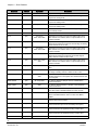
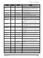
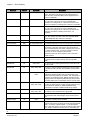
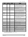
1
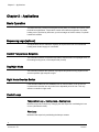
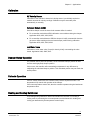
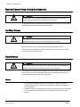
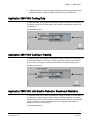
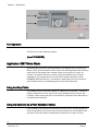
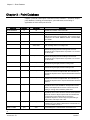
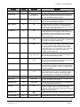
Siemens BACnet ATEC Owner's Manual Siemens Industry, Inc. 125-5050, Rev. AA Technical specifications and availability subject to change without notice. © 2010 Copyright Siemens Industry, Inc. We reserve all rights in this document and in the subject thereof. By acceptance of the document the recipient acknowledges these rights and undertakes not to publish the document nor the subject thereof in full or in part, nor to make them available to any third party without our prior express written authorization, nor to use it for any purpose other than for which it was delivered to him. Copyright Notice Copyright Notice Notice Document information is subject to change without notice by Siemens Industry, Inc. Companies, names, and various data used in examples are fictitious unless otherwise noted. No part of this document may be reproduced or transmitted in any form or by any means, electronic or mechanical, for any purpose, without the express written permission of Siemens Industry, Inc. Warning This equipment generates, uses, and can radiate radio frequency energy. If equipment is not installed and used in accordance with the instructions manual, it may cause interference to radio communications. Equipment has been tested and found to comply within the limits for a Class B digital device pursuant to Part 15 of the FCC rules. These limits are designed to provide reasonable protection against such interference when operated in a commercial environment. Operation of this equipment in a residential area is likely to cause interference. Residential area equipment users are required to take whatever measures necessary to correct the interference at their own expense. Service Statement Control devices are combined to make a system. Each control device is mechanical in nature and all mechanical components must be regularly serviced to optimize their operation. Siemens Industry, Inc. branch offices and authorized distributors offer Technical Support Programs that will ensure continuous, trouble-free system performance. For further information, contact your nearest Siemens Industry, Inc. representative. Copyright 2010 by Siemens Industry, Inc. FCC Regulations The manual for an intentional or unintentional radiator shall caution the user that changes or modifications not expressly approved by the party responsible could void the user’s authority to operate the equipment. For a Class B digital device or peripheral, the instructions furnished the user shall include the following or similar statement, placed in a prominent location in the text of the manual: NOTE: This equipment has been tested and found to comply with the limits for a Class B digital device, pursuant to part 15 of the FCC Rules. These limits are designed to provide reasonable protection against harmful interference in a residential installation. This equipment generates, uses and can radiate radio frequency energy and, if not installed and used in accordance with the instructions, may cause harmful interference to 3 Siemens Industry, Inc. 125-5050, Rev. AA BACnet ATEC Owner's Manaul 4/20/2010 Copyright Notice radio communications. However, there is no guarantee that interference will not occur in a particular installation. If this equipment does cause harmful interference to radio or television reception, which can be determined by turning the equipment off and on, the user is encouraged to try to correct the interference by one or more of the following measures: Reorient or relocate the receiving antenna. Increase the separation between the equipment and receiver. Connect the equipment into an outlet on a circuit different from that to which the receiver is connected. Consult the dealer or an experienced radio/TV technician for help. To the Reader Your feedback is important to us. If you have comments about this manual, please submit them to: mailto:[email protected] Credits APOGEE, APOGEE GO, InfoCenter Administrator, InfoCenter Report Manager, InfoCenter Server, InfoCenter Suite, Insight, Staefa, and TALON are registered trademarks of Siemens Industry, Inc. Other product or company names mentioned herein may be the trademarks of their respective owners. Printed in USA 4 Siemens Industry, Inc. 125-5050, Rev. AA BACnet ATEC Owner's Manaul 4/20/2010 Table of contents Copyright Notice .......................................................................................3 How To Use This Manual .......................................................................... 7 Chapter 1 – Product Overview ................................................................. 9 Hardware Inputs ...................................................................................................... 10 Hardware Outputs ................................................................................................... 10 Power Wiring ...................................................................................................... 11 Communication Wiring ....................................................................................... 12 Controller LED Indicators ................................................................................... 12 Temperature Sensors .............................................................................................. 13 Room Temperature Sensor ................................................................................ 13 Duct Temperature Sensor .................................................................................. 13 Related Equipment ............................................................................................. 13 Chapter 2 – Applications ........................................................................ 14 Basic Operation ....................................................................................................... 14 Sequencing Logic (optional) ............................................................................... 14 Control Temperature Setpoints .......................................................................... 14 Day/Night Mode .................................................................................................. 14 Night Mode Override Switch............................................................................... 14 Control Loops ..................................................................................................... 14 Calibration .......................................................................................................... 15 Damper Status Operation................................................................................... 15 Fail-safe Operation ............................................................................................. 15 Heating and Cooling Switchover ........................................................................ 15 Modulate Damper During Heating Mode (optional)............................................ 16 Hot Water Reheat ............................................................................................... 16 Electric Reheat ................................................................................................... 16 Notes .................................................................................................................. 16 Application 2860 VAV Cooling Only ........................................................................ 17 Application 2861 VAV Cooling or Heating ............................................................... 17 Application 2862 VAV with Electric Reheat or Baseboard Radiation ...................... 17 Baseboard Radiation .......................................................................................... 18 Electric Heat Interlock ........................................................................................ 18 Application 2863 VAV with Hot Water Reheat ........................................................ 18 Application 2864 VAV Series Fan Powered with Electric Reheat ........................... 19 Fan Operation .................................................................................................... 19 Application 2865 VAV Series Fan Powered with Hot Water Reheat ...................... 20 Fan Operation .................................................................................................... 20 Application 2866 VAV Parallel Fan Powered with Electric Reheat ......................... 20 Fan Operation .................................................................................................... 21 Application 2867 VAV Parallel Fan Powered with Hot Water Reheat ..................... 21 Fan Operation .................................................................................................... 22 Application 2897 Slave Mode .................................................................................. 22 Using Auxiliary Points ......................................................................................... 22 5 Siemens Industry, Inc. 125-5050, Rev. AA BACnet ATEC Owner's Manaul 4/20/2010 Using the Controller as a Point Extension Device ..............................................22 Chapter 3 – Point Database ................................................................... 24 Chaper 4 – Troubleshooting .................................................................. 30 Basic Service Information ........................................................................................ 30 Preventive Maintenance .......................................................................................... 30 Safety Features ....................................................................................................... 31 Controller LEDs ....................................................................................................... 31 Glossary .................................................................................................. 32 Index ........................................................................................................ 35 6 Siemens Industry, Inc. 125-5050, Rev. AA BACnet ATEC Owner's Manaul 4/20/2010 How To Use This Manual How To Use This Manual This manual is written for the owner and user of the Siemens Industry BACnet VAV Actuator. It is designed to help you become familiar with the Siemens BACnet VAV Actuator and its applications. This section covers manual organization, manual conventions, symbols used in the manual, and other information that will help you use this manual. Manual Organization This manual contains the following chapters: Chapter 1, Hardware, describes the hardware components and the accessories that are used with the BACnet VAV Actuator. Chapter 2, Applications for BACnet VAV Actuator, describes the control applications available in the model of the BACnet VAV Actuator that includes a terminal block for wireable input/output connections. Chapter 3, Point Database, defines the point database descriptors and includes address and applications. Chapter 4, Troubleshooting, describes basic corrective measures you can take should you encounter a problem when using the BACnet VAV Actuator. For issues not covered in this chapter, consult your local Siemens Industry representative. The Glossary describes the terms and acronyms used in this manual. The Index helps you locate information presented in this manual. Manual Conventions The following table lists conventions to help you use this manual in a quick and efficient manner. Convention Examples Numbered Lists (1, 2, 3…) indicate a procedure with sequential steps. 1. Turn OFF power to the field panel. 2. Turn ON power to the field panel. 3. Contact y the local Siemens Building Technologies representative. Conditions that must be completed or met before beginning a task are designated with a ⊳. Intermediate results (what will happen following the execution of a step), are designated with a ⇨. Results, which inform the user that a task was completed successfully, are designated with a ⇨. ⊳Composer software is properly installed. ⊳A Valid license is available. 1. Select Start > Programs > Siemens > GMS > Composer. ⇨The Project Management window displays. 2. Open an existing project or create a new one. ⇨The project window displays. Actions that should be performed are specified Type F for Field panels. in boldface font. Click OK to save changes and close the 7 Siemens Industry, Inc. 125-5050, Rev. AA BACnet ATEC Owner's Manaul 4/20/2010 How To Use This Manual Convention Examples dialog box. Error and system messages are displayed in Courier New font. The message Report Definition successfully renamed displays in the status bar. New terms appearing for the first time are italicized. The PXC Modular continuously executes a user-defined set of instructions called the control program. This symbol signifies Notes. Notes provide additional information or helpful hints. Cross references to other information are indicated with an arrow and the page number, enclosed in brackets: [→92] For more information on creating flowcharts, see Flowcharts [→92]. Manual Symbols The following table lists the safety symbols used in this manual to draw attention to important information. Symbol Meaning Description NOTICE CAUTION Equipment damage may occur if a procedure or instruction is not followed as specified. (For online documentation, the NOTICE displays in white with a blue background.) CAUTION Minor or moderate injury may occur if a procedure or instruction is not followed as specified. WARNING Personal injury or property damage may occur if a procedure or instruction is not followed as specified. DANGER Electric shock, death, or severe property damage may occur if a procedure or instruction is not followed as specified. Getting Help For more information about the BACnet VAV Actuator, contact your local Siemens Industry representative. Where to Send Comments Your feedback is important to us. If you have comments about this manual, please submit them to [email protected] 8 Siemens Industry, Inc. 125-5050, Rev. AA BACnet ATEC Owner's Manaul 4/20/2010 Chapter 1 – Product Overview Chapter 1 – Product Overview The BACnet Actuating Terminal Equipment Controller (ATEC) is the Siemens Industry FLN controller used in pressure independent Variable Air Volume applications (See the following figure.). It provides Direct Digital Control (DDC) for eight applications, and can operate independently as a stand-alone DDC room controller or networked with a field panel. The controller provides all input/output, system, and local communication connections. Hardware consists of the controller and the mounting bracket. Table 1 lists the BACnet ATEC products that are covered: Table 1. BACnet ATEC – Electronic Output Applications. Application Number Application Description 2860 VAV Cooling Only 2861 VAV Cooling or Heating 2862 VAV with Electronic Reheat or Baseboard Radiation 2863 VAV with Hot Water Reheat 2864 VAV Series Fan Powered with Electric Reheat 2865 VAV Series Fan Powered with Hot Water Reheat 2866 VAV Parallel Fan Powered with Electric Reheat 2867 VAV Parallel Fan Powered with Hot Water Reheat 2897 Slave Mode Ordering Notes Part Number Description 550-440 BACnet ATEC Model 0001, cooling only (GDE) 550-441 BACnet ATEC Model 0001, cooling only (GLB) 550-445 BACnet ATEC Model 2301, full feature (GDE) 550-446 BACnet ATEC Model 2301, full feature (GLB) 9 Siemens Industry, Inc. 125-5050, Rev. AA BACnet ATEC Owner's Manaul 4/20/2010 Chapter 1 – Product Overview Siemens BACnet ATEC Hardware Inputs Analog Air Velocity Sensor (AVS) Duct temperature sensor (optional) – Application 2861 Room temperature sensor (RTS) Room temperature setpoint dial (optional) Digital Night mode override (optional) Wall switch (optional) Hardware Outputs Analog None 10 Siemens Industry, Inc. 125-5050, Rev. AA BACnet ATEC Owner's Manaul 4/20/2010 Chapter 1 – Product Overview Digital Application Damper Actuator All Fan 2865, 2866, 2867 First valve actuator (required) 2863 Stage 1 electric reheat; or, 2-position heating valve 2862 Stage 1 electric reheat 2864, 2866 Stage 2 electric reheat (optional) 2862, 2864, 2866 Stage 3 electric reheat (optional) 2862 Valve actuator 2865, 2867 Power Wiring The controller is powered by 24 Vac. Power wiring connects to the two screw terminals on the controller labeled “C” (Common) and “H” (Hot) on the terminal block labeled “24 VAC”. No earth ground connection is required. See the following figure. 11 Siemens Industry, Inc. 125-5050, Rev. AA BACnet ATEC Owner's Manaul 4/20/2010 Chapter 1 – Product Overview Communication Wiring The controller connects to the field panel by means of a Floor Level Network (FLN) trunk. Communication wiring connects to the three screw terminals on the controller labeled “+” (positive), “-“(negative), and “S” (Shield). See the following figure. Controller LED Indicators The controller has six Light Emitting Diode (LED) indicators (see the figure Siemens BACnet ATEC). Controller LEDs. LED Type Label (if present)* LED Number Indication DO LED 3 - LED 5 3-5 Transmit TX 0 Indicates, when flashing, that the controller is transmitting information to the field panel. Receive RX 1 Indicates, when flashing, that the controller is receiving information from the field panel. BST ”Basic Sanity Test” BST 2 Indicates, when flashing ON and OFF once per second, that the controller is functioning properly. Indicates the ON/OFF status of the DO associated with it. A glowing LED indicates that the DO is energized. * Some LED labels and numerals may be hidden by the controller cover. See also Chapter 1 – Product Overview [ 9] 12 Siemens Industry, Inc. 125-5050, Rev. AA BACnet ATEC Owner's Manaul 4/20/2010 Chapter 1 – Product Overview Temperature Sensors Room Temperature Sensor The controller room temperature sensor connects to the controller by means of a cable terminated at both ends with a six-conductor RJ-11 plug-in connector. Duct Temperature Sensor An optional duct temperature sensor provides duct air temperature sensing inputs to the controller. For more information about temperature sensors, contact your local Siemens Industry representative. Related Equipment Autozero Module (optional) 540-200 Relay Module Damper Actuator(s) Duct Temperature Sensor (optional) Room Temperature Sensor Contact your local Siemens Industry representative for product numbers and more information. 13 Siemens Industry, Inc. 125-5050, Rev. AA BACnet ATEC Owner's Manaul 4/20/2010 Chapter 2 – Applications Chapter 2 – Applications Basic Operation The BACnet ATEC provides Direct Digital Control (DDC) for Variable Air Volume (VAV) terminal box applications. Temperature control varies with the application. If present, heating can be provided by hot water, up to three stages of electric reheat, or optional baseboard radiation. Sequencing Logic (optional) This application has the additional capability to sequence the flow and mechanical heating when heated supply air is available. Control Temperature Setpoints The controller maintains a specified temperature setpoint based on Day/Night mode, or the heating/cooling mode, or the setpoint dial (if used). Day/Night Mode The controller maintains the specified day setpoint temperature during daytime hours and the specified night setpoint at night. Night Mode Override Switch If the ROOM TEMPERATURE SENSOR has an override switch, it can be used to command the controller into day mode for an adjustable period of time. This only affects a controller in night mode. Control Loops Temperature Loop – Heating Loop – Cooling Loop Maintain temperature setpoint by changing the flow setpoint or modulating the heat source (valve/electric heat). Flow Loop Maintains flow setpoint by modulating the damper actuator. 14 Siemens Industry, Inc. 125-5050, Rev. AA BACnet ATEC Owner's Manaul 4/20/2010 Chapter 2 – Applications Calibration Air Velocity Sensor Calibration of the controller's internal air velocity sensor is periodically required to maintain accurate air velocity readings. Calibration may be set to take place automatically or manually. Autozero Module (AZM) Used when damper cannot be closed and constant airflow is needed. For a controller used with an AZM, calibration occurs without closing the damper. Application 6520, 6521, 6522, 6523. For a controller used without an AZM, the damper is briefly commanded closed to get a zero airflow reading and an accurate damper position during calibration. Application 6520, 6521, 6522, 6523. Hot Water Valve Calibration of a hot water valve (if used) is done by briefly commanding the valve closed. Application 2863, 2865, 2867. Damper Status Operation It is possible, after a period of operation, for the calculated damper position to differ from the actual (physical) damper position. If this occurs, the controller will automatically compensate for any difference by readjusting the calculated damper position. This calculated position may not match the actual position. Fail-safe Operation If the air velocity sensor fails, the controller uses pressure dependent control. The temperature loop controls the operation of the damper. If the room temperature sensor fails, then the controller operates using the last known temperature value. Heating and Cooling Switchover The heating/cooling switchover determines whether the controller is in heating or cooling mode by monitoring the room temperature and the demand for heating and cooling (as determined by the temperature control loops). 15 Siemens Industry, Inc. 125-5050, Rev. AA BACnet ATEC Owner's Manaul 4/20/2010 Chapter 2 – Applications Modulate Damper During Heating Mode (optional) CAUTION If the damper is set to modulate in heating mode, make sure the controller is in the appropriate mode for the current supply air temperature. Applications that have a heating source (valve/electric) can be configured to modulate the flow setpoint in sequence with the heating source. Hot Water Reheat CAUTION Do not set HTG FLOW MIN to 0 cfm (0 lps). A minimum airflow should be provided across the heating coils when the heating valve is open. When the controller is in cooling mode, the heating valve(s) are closed. The heating loop modulates the heating valve(s) to warm up the room. In cooling mode, the heating valve is closed. Electric Reheat CAUTION Verify that the equipment is supplied with safeties by others to ensure that there is airflow across the heating coils when they are to be energized. The heating loop controls up to three stages of electric reheat to warm up the room. The electric reheat is time modulated using a duty cycle. When the controller is in cooling mode, the electric heat is OFF at all times. Notes 1. If the temperature swings in the room are excessive or if there is trouble in maintaining the setpoint, contact your local Siemens Industry representative for more information. 2. The BACnet ATEC, as shipped from the factory, keeps all associated equipment OFF. The controller and its equipment are released to application control at start-up. 16 Siemens Industry, Inc. 125-5050, Rev. AA BACnet ATEC Owner's Manaul 4/20/2010 Chapter 2 – Applications 3. “Safeties by Others”: This note implies that the associated equipment has safety features installed, for example adding mechanical stops to the dampers. Application 2860 VAV Cooling Only In Application 2860, the controller modulates the supply air damper of the terminal box for cooling. In order for it to work properly, the central air-handling unit must provide cool supply air. See the following figure. Application 2861 VAV Cooling or Heating In Application 2861, the controller modulates the supply air damper of the terminal box for cooling and heating. In order for it to work properly, the central air-handling unit must provide cool supply air in cooling mode and warm air during heating mode. See the following figure. Application 2862 VAV with Electric Reheat or Baseboard Radiation In Application 2862, the controller modulates the supply air damper of the terminal box for cooling and controls stages of electric reheat or baseboard radiation for heating. When in heating, the terminal box either maintains minimum airflow or modulates the supply air damper. In order for the terminal box to work properly, the central airhandling unit must provide supply air. See the following figure. 17 Siemens Industry, Inc. 125-5050, Rev. AA BACnet ATEC Owner's Manaul 4/20/2010 Chapter 2 – Applications Baseboard Radiation Baseboard radiation can be a two-position valve or electrical resistance heating. If the controller is in cooling mode, the heating valve is closed. When in heating mode, the controller will operate the heating valve to maintain the heating setpoint. Electric Heat Interlock CAUTION Do not set EHEAT FLOW (the defined minimum) to less than 5%; otherwise, the electric heat interlock will be disabled. The electric heat stages will be disabled (turned off) when the electric heat airflow is less than the defined minimum. Application 2863 VAV with Hot Water Reheat In Application 2863, the controller modulates the supply air damper of the terminal box for cooling and controls a hot water valve or baseboard radiation for heating. When in heating, the terminal box either maintains minimum airflow or modulates the supply air damper. In order for the terminal box to work properly, the central air-handling unit must provide supply air for cooling. See the following figures. 18 Siemens Industry, Inc. 125-5050, Rev. AA BACnet ATEC Owner's Manaul 4/20/2010 Chapter 2 – Applications Application 2864 VAV Series Fan Powered with Electric Reheat In Application 2864, the controller modulates the supply air damper of the terminal box for cooling and controls stages of electric reheat for heating. When in heating, the terminal box either maintains minimum airflow or modulates the supply air damper. Application 2864 has a series fan for air circulation. In order for the terminal box to work properly, the central air-handling unit must provide supply air. See the following figure. Fan Operation CAUTION On series fan powered terminal boxes, the terminal box fan must be controlled/interlocked to start either before or at the same time as the central air handler. Failure to do so may cause the terminal box fan to rotate backwards and cause consequent damage at start up. In day mode, the fan is ON all the time. In night mode, the fan cycles on when heating or cooling is required. 19 Siemens Industry, Inc. 125-5050, Rev. AA BACnet ATEC Owner's Manaul 4/20/2010 Chapter 2 – Applications [insert TEC2564CD] Application 2865 VAV Series Fan Powered with Hot Water Reheat In Application 2865, the controller modulates the supply air damper of the terminal box for cooling and modulates a hot water valve for heating. When in heating, the terminal box either maintains minimum airflow or modulates the supply air damper. Application 2865 has a series fan for air circulation. In order for the terminal box to work properly, the central air-handling unit must provide supply air. See the following figure. Fan Operation CAUTION On series fan powered terminal boxes, the terminal box fan must be controlled/interlocked to start either before or at the same time as the central air handler. Failure to do so may cause the terminal box fan to rotate backwards and cause consequent damage at start up. In day mode, the fan is ON all the time. In night mode, the fan cycles on when heating or cooling is required. Application 2866 VAV Parallel Fan Powered with Electric Reheat In Application 2866, the controller modulates the supply air damper of the terminal box for cooling and controls stages of electric reheat for heating. When in heating, the terminal box either maintains minimum airflow or modulates the supply air damper. Application 2866 has a parallel fan that re-circulates the room air. In order for the terminal box to work properly, the central air-handling unit must provide supply air. 20 Siemens Industry, Inc. 125-5050, Rev. AA BACnet ATEC Owner's Manaul 4/20/2010 Chapter 2 – Applications See the following figure. Fan Operation The fan turns on when heating is required. [insert TEC2566CD] Application 2867 VAV Parallel Fan Powered with Hot Water Reheat In Application 2867, the controller modulates the supply air damper of the terminal box for cooling and modulates a hot water valve for heating. When in heating, the terminal box either maintains minimum airflow or modulates the supply air damper. Application 2867 has a parallel fan that re-circulates the room air. In order for the terminal box to work properly, the central air-handling unit must provide supply air. See the following figure. 21 Siemens Industry, Inc. 125-5050, Rev. AA BACnet ATEC Owner's Manaul 4/20/2010 Chapter 2 – Applications Fan Operation The fan turns on when heating is required. [insert TEC2567CD] Application 2897 Slave Mode Application 2897 is the slave mode application for the BACnet ATEC (see Ordering Notes [ 9] for product numbers). Slave mode is the default application that comes up when power is first applied to the controller. Slave mode provides no control. Its purpose is to allow the operator to perform equipment checkout before a control application is put into effect and to set some basic controller parameters (CTLR ADDRESS, APPLICATION, etc.). A controller in default state can also be used as a point extension device by unbundling spare I/O points at the field panel. Using Auxiliary Points It is possible to have extra points available on a BACnet VAV Controller — Electronic Output in addition to the ones used by the current application that is running in the controller. If these extra points are to be controlled by a field panel, then they must be unbundled at the field panel. Using the Controller as a Point Extension Device If the controller is only used as a point extension device, with no control application in affect, its application must be set to slave mode and points must be unbundled at the field panel. All points must be controlled from the field panel in order to be used. 22 Siemens Industry, Inc. 125-5050, Rev. AA BACnet ATEC Owner's Manaul 4/20/2010 Chapter 2 – Applications DO 3, DO 4, and DO 5 may be used as separate DOs or in pairs to control a motor as shown in the example. NOTE: If using either a motor or DOs as auxiliary points, be sure to set MTR SETUP to the correct value. If using a pair of DOs to control a motor, then the DOs cannot be unbundled. Only MTR COMD can be unbundled to control the motors. Contact your local Siemens Industry representative for other combinations of DOs and motors. 23 Siemens Industry, Inc. 125-5050, Rev. AA BACnet ATEC Owner's Manaul 4/20/2010 Chapter 3 – Point Database Chapter 3 – Point Database Chapter 3 presents a description of the BACnet VAV Controller — Electronic Output point database, including point descriptors, point addresses, and a listing of applications in which each point is found. Descriptor Address1 Application CTLR ADDRESS 01 All Identifies the controller on the FLN trunk. APPLICATION 02 All Identification number of the program running in the controller. RMTMP OFFSET 03 All Compensates for deviations between the value of ROOM TEMP and the actual room temperature. This corrected value is displayed in CTL TEMP. RMTMP OFFSET + ROOM TEMP = CTL TEMP ROOM TEMP {04}2 All Actual reading from the room temperature sensor. HEAT.COOL {05} All except 2560, 2597 DAY CLG STPT 06 All except 2597 The temperature setpoint in degrees that the controller maintains during day periods in cooling mode if a room temperature sensor setpoint dial is not present or is not used. See STPT DIAL. DAY HTG STPT 07 All except 2560, 2597 The temperature setpoint in degrees that the controller maintains during day periods in heating mode if a room temperature sensor setpoint dial is not present or is not used. See STPT DIAL. NGT CLG STPT 08 All except 2597 The temperature setpoint in degrees that the controller maintains during the night periods in cooling mode. NGT HTG STPT 09 All except 2560, 2597 The temperature setpoint in degrees that the controller maintains during the night periods in heating mode. RM STPT MIN 11 All except 2597 The minimum temperature setpoint in degrees that the controller can use from the setpoint dial. This overrides any temperature setpoint from the setpoint dial that falls below this minimum. RM STPT MAX 12 All except 2597 The maximum temperature setpoint in degrees that the controller can use from the setpoint dial. This overrides any temperature setpoint from the setpoint dial that falls above this maximum. RM STPT DIAL {13}2 All 14 All except 2597 YES indicates that there is a room setpoint dial on the room temperature sensor and it should be used as the temperature setpoint for control in day/occupied mode. NO indicates that the appropriate preset setpoint will be used as the temperature setpoint for control in day/occupied heating or cooling mode. Valid input: YES or NO. AUX TEMP UI 1 {15} All except 2561 Actual reading from a 10K thermistor connected to the controller's Ul 1 input. When a thermistor is connected at Ul 1, UI 1 is not available. See UI 1. SUPPLY TEMP {15} 2561 STPT DIAL Description Current mode of operation for applications that can be in either a heating mode or a cooling mode. The temperature setpoint in degrees from the room temperature sensor (not available on all temperature sensor models). This setpoint will be used for control in day mode (heating or cooling) when enabled by STPT DIAL. Actual reading from a 10K thermistor connected to the 24 Siemens Industry, Inc. 125-5050, Rev. AA BACnet ATEC Owner's Manaul 4/20/2010 Chapter 3 – Point Database Descriptor Address1 Application FLOW START 16 All except 2560, 2561, 2597 Determines how the damper modulation will be sequenced while in heating mode. When HTG LOOPOUT is above this value, then FLOW STPT starts to increase. FLOW END 17 All except 2560, 2561, 2597 Determines how the damper modulation will be sequenced while in heating mode. When HTG LOOPOUT is below this value, then FLOW STPT starts to decrease. WALL SWITCH 18 All YES indicates that the controller is to monitor the status of a wall switch that is connected to UI 2. NO indicates that the controller will not monitor the status of a wall switch, even if one is connected. Valid input: YES or NO. DI OVRD SW {19}2 All Actual indication of the status of the override switch (not physically available on all temperature sensor models) at the room temperature sensor. ON indicates that the switch is being pressed. OFF indicates that the switch is released. Valid input: ON or OFF. OVRD TIME 20 All except 2597 The amount of time in hours that the controller will operate in day/occupied mode when the override switch is pressed while the controller is in night/unoccupied mode. NGT OVRD {21}2 All except 2597 Indicates the mode that the controller is operating in with respect to the override switch. NIGHT indicates that the switch has not been pressed and the override timer is not active. DAY indicates that the switch has been pressed and the override timer is active. The controller then uses a day mode temperature setpoint. This point is only in effect when DAY.NGT indicates night mode. REHEAT START 22 All except 2560, 2561, 2597 REHEAT END 23 DIGITAL UI 2 {24} All Actual status of a contact connected to the controller at UI 2. ON indicates that the contact is closed; OFF indicates that the contact is open. If a wall switch is used, it is connected to UI 2. See WALL SWITCH. DIGITAL UI 1 {25}2 All except 2561 Actual status of a contact connected to the controller UI 1. ON indicates that the contact is closed; OFF indicates that the contact is open. When a contact is connected as a digital input, the analog input is not available. See AUX TEMP. SERIES ON 26 2564, 2565 When flow rises above this value, the series fan will turn ON. SERIES OFF 27 2564, 2565 When flow drops below this value and other conditions have been met, the series fan will turn OFF. PARALLEL ON 28 2566, 2567 When flow drops below this value and other conditions have been met, the parallel fan will turn ON. {29} All PARALLEL OFF 30 2566, 2567 CLG FLOW MIN 31 All except 2597 DAY.NGT Description controller's Ul 1 input. The controller uses this value to determine whether it is in heating or cooling mode. Determines how the reheat modulation will be sequenced while in heating mode. When HTG LOOPOUT is above this value, then the reheat modulates upward. All except 2560, 2561, Determines how the reheat modulation will be sequenced 2597 while in heating mode. When HTG LOOPOUT is below this value, then the reheat modulates downward. Indicates the mode in which the controller is operating. Day temperature setpoints will be used in day mode. Night temperature setpoints will be used in night mode. This point is normally set by the field panel. When flow rises above this value, the parallel fan will turn OFF. The minimum amount of air in CFM (LPS) to be supplied to 25 Siemens Industry, Inc. 125-5050, Rev. AA BACnet ATEC Owner's Manaul 4/20/2010 Chapter 3 – Point Database Descriptor Address1 Application Description the space in cooling mode. CLG FLOW MAX 32 All except 2597 The maximum amount of air in CFM (LPS) to be supplied to the space in cooling mode. HTG FLOW MIN 33 All except 2560, 2597 The minimum amount of air in CFM (LPS) to be supplied to the space in heating mode. HTG FLOW MAX 34 All except 2560, 2597 The maximum amount of air in CFM (LPS) to be supplied to the space in heating mode. AIR VOLUME {35}2 All Actual amount of air in CFM (LPS) currently passing through the air velocity sensor. FLOW COEFF 36 All Calibration factor for the airflow sensor. DO 3 {43} All except 2562, 2564, 2566 Digital output 3 controls a 24 Vac load with an ON or OFF status. If Motor 2 is enabled, DO 3 is coupled with DO 4 to control an actuator. HEAT STAGE 1 {43} 2562, 2564, 2566 This point is DO 3 in applications with electric reheat. This digital output controls the contact for the first stage of heating and has a status of ON or OFF. DO 4 {44} All except 2562, 2564, 2566 Digital output 4 controls a 24 Vac load with an ON or OFF status. If Motor 2 is enabled, DO 4 is coupled with DO 3 to control an actuator. HEAT STAGE 2 {44} 2562, 2564, 2566 This point is DO 4 in applications with electric reheat. This digital output controls the contact for the second stage of heating and has a status of ON or OFF. DO 5 {45} 2560, 2561, 2563, 2597 Digital output 5 controls a 24 Vac load with an ON or OFF status. If Motor 3 is enabled, DO 5 is coupled with DO 6 to control an actuator. DO 5 {45} 2565, 2567 Digital output 5 controls a 24 Vac load with an ON or OFF status. HEAT STAGE 3 {45}2 2562, 2564, 2566 This point is a digital output used to control the contact for the third stage of heating and has a status of ON or OFF. FAN {46} 2564, 2565, 2566, 2567 This point is a digital output used to control the fan. ON indicates that the DO is energized; OFF indicates that the DO is de-energized. DMPR COMD {48} All except 2597 MTR1 COMD {48} 2597 The value to which the Motor 1 actuator is commanded in percent of full travel. DMPR POS {49} All except 2597 The current position of the damper motor in percent of full travel. This value is calculated based on motor run time. MTR1 POS {49} 2597 The current position of Motor 1 in percent of full travel. This value is calculated based on motor run time. See MTR1 TIMING. MTR1 TIMING 51 All The time required for the Motor 1 actuator to travel from full closed to the full open position. MTR2 COMD {52}2 2560, 2561, 2597 The value to which the Motor 2 actuator is commanded in percent of full travel (for use as an auxiliary slave point). VLV COMD {52} 2565, 2567 The value to which the valve actuator is commanded in percent of full travel for applications using a water valve. VLV1 COMD {52} 2563 The value to which the valve 1 actuator is commanded in percent of full travel for applications using a water valve. MTR2 POS {53} 2560, 2561, 2597 The value to which the damper motor is commanded in percent of full travel. The current position of the Motor 2 actuator in percent of full 26 Siemens Industry, Inc. 125-5050, Rev. AA BACnet ATEC Owner's Manaul 4/20/2010 Chapter 3 – Point Database Descriptor Address1 Application Description travel (for use as an auxiliary slave point). This value is calculated based on motor run time. See MTR2 TIMING. VLV POS {53} 2565 The current position of the valve in percent of full travel for applications using a water valve. This value is calculated based on motor run time. VLV1 POS {53} 2563 The current position of valve 1 in percent of full travel for applications using a water valve. This value is calculated based on motor run time. MTR2 TIMING 55 All except 2562, 2564, 2566 DMPR ROT ANG 56 All except 2597 DPR1 ROT ANG 56 2597 The number of degrees that damper 1 is free to travel. DPR2 ROT ANG 57 2597 The number of degrees that damper 2, the hot duct damper, is free to travel. MTR SETUP 58 All The configuration setup code for Motors 1 and 2. This enables the motors individually and sets each motor to be either direct or reverse acting. Note: When a motor is enabled, its associated DOs are enabled. DO DIR.REV 59 All The configuration setup code for DOs. Allows the DOs to be direct or reverse acting (enabled equals energized or disabled equals de-energized). EHEAT FLOW 60 2562 The flow required before the electric heat will be enabled. COOL TEMP 61 2561 The discharge air temperature where the controller will switch from heating to cooling mode. Used only in applications with SUPPLY TEMP. HEAT TEMP 62 2561 The discharge air temperature where the controller will switch from cooling to heating mode. Used only in applications with SUPPLY TEMP. CLG P GAIN 63 All except 2597 The proportional gain value for the cooling temperature control loop. CLG l GAIN 64 All except 2597 The integral gain value for the cooling temperature control loop. CLG D GAIN 65 All except 2597 The derivative gain value for the cooling temperature control loop. CHK OUT 66 All The procedure tests all of the necessary I/O and ensures the controller has the ability to operate within the set airflow range, between CLG FLOW MIN and CLG FLOW MAX. HTG P GAIN 67 All except 2560, 2597 HTG l GAIN 68 All except 2560, 2597 The integral gain value for the heating temperature control loop. HTG D GAIN 69 All except 2560, 2597 The derivative gain value for the heating temperature control loop. CHK STATUS 70 All FLOW P GAIN 71 All except 2597 The proportional gain value for the flow control loop. FLOW l GAIN 72 All except 2597 The integral gain value for the flow control loop. FLOW D GAIN 73 All except 2597 The derivative gain value for the flow control loop. FLOW BIAS 74 All except 2597 The biasing of the flow control loop. The time required for the Motor 2 actuator to travel from full closed to the full open position. The number of degrees the damper is free to travel. The proportional gain value for the heating temperature control loop. Displays the results of CHK OUT. 27 Siemens Industry, Inc. 125-5050, Rev. AA BACnet ATEC Owner's Manaul 4/20/2010 Chapter 3 – Point Database Descriptor Address1 Application FLOW {75}2 Description All except 2597 Indicates the amount of air currently passing the air velocity sensor. The value is calculated as a percentage based on where the value of AIR VOLUME is in the range between 0 and CTL FLOW MAX. CTL FLOW MIN {76}2 All except 2597 The active minimum flow used as a limit for the flow control loop. This value is the same as CLG FLOW MIN if the controller is in cooling mode, or is the same as HTG FLOW MIN if the controller is in heating mode, unless it is overridden. CTL FLOW MAX {77} All except 2597 The active maximum flow used as a limit for the flow control loop. This value is the same as CLG FLOW MAX if the controller is in cooling mode, or is the same as HTG FLOW MAX if the controller is in heating mode unless, it is overridden. CTL TEMP {78} All except 2597 The temperature used as input for the temperature control loops. This value is the same as the value in ROOM TEMP and RM TEMP OFFSET unless it is overridden. CLG LOOPOUT {79} All except 2597 The cooling temperature control loop output value in percent. HTG LOOPOUT {80} All except 2560, 2597 The heating temperature control loop output value in percent. AVG HEAT OUT {81}2 2562, 2564, 2566 This point is used to determine what stages of electric heat are used for a given loop output value. The ranges for the value are determined by the number of stages used: 0 to 100 for 1 stage of electric heat, 0 to 200 for 2 stages of electric heat, and 0 to 300 for 3 stages of electric heat. With electric heat, this value is equal to: HTG LOOPOUT × STAGE COUNT. STAGE MAX 82 2562, 2564, 2566 The value, in percent, which the heating loop must exceed for the electric heat to be ON for the full duty cycle (STAGE TIME). STAGE FAN 83 2565, 2567 The valve must be opened greater than this value before the fan will turn ON. STAGE MIN 83 2562, 2564, 2566 The value, in percent, which the heating loop must go below for the electric heat to be OFF for the full duty cycle (STAGE TIME). DMPR STATUS {84}2 2560, 2561, 2562, 2563 This point is used only when CAL MODULE set to YES. It readjusts the damper position if the command value is not equal to the actual position of the damper. CAL indicates that the damper is operating normally. RECAL indicates that the damper position was adjusted (recalibrated) by 25% because the desired airflow was not obtainable under its current status. SWITCH LIMIT 85 All except 2560, 2561, 2597 The active temperature control loop output must be less than this value to switch between cooling mode and heating mode. Actual switchover depends on SWITCH DBAND being exceeded and is subject to SWITCH TIME being expired. SWITCH TIME 86 All except 2560, 2561, 2597 The time, in minutes, before the heat/cool mode can change over when the other parameters are appropriate. STAGE COUNT 88 2562, 2564, 2566 The number of electric heating stages used by the application. DOs associated with unused stages may be used as spare DOs. VALVE COUNT 88 2563 STAGE TIME 89 2562, 2564, 2566 The number of heating valves available. The cycle time in minutes for the electric reheat stages. For example, if there are three stages of electric heat and STAGE TIME = 10 minutes, STAGE COUNT = 3, and AVG HEAT OUT = 150% then, Stage 1 is ON for 10 minutes (100% of the time), Stage 2 is ON for 5 minutes (50% of 10 minutes) and 28 Siemens Industry, Inc. 125-5050, Rev. AA BACnet ATEC Owner's Manaul 4/20/2010 Chapter 3 – Point Database Descriptor Address1 Application 90 All except 2560, 2561, 2597 CTL STPT {92} All except 2597 The actual setpoint value being used as input for the active temperature control loop. FLOW STPT {93} All except 2597 The setpoint of the flow control loop. CAL AIR {94} All YES commands the controller to go through calibration sequence for the air velocity transducers. YES is also displayed when the calibration sequence is started automatically. CAL AIR automatically returns to NO after the calibration sequence is completed. Valid input: YES or NO. CAL SETUP 95 All The configuration setup code for the calibration sequence options. CAL TIMER 96 All Time interval, in hours, between the calibration sequence initiations if a timed calibration option is selected in CAL SETUP. DUCT AREA 97 All Area, in square feet (square meters), of the duct where the air velocity sensor is located. This is a calculated value (calculated by the field panel or computer being used) that depends on duct shape and size. It is used in calculating all points in units of CFM, CF, LPS and L. Valid input: .025 ft2 (.002 m2) through 6.375 ft2 (.5923 m2). LOOP TIME 98 All except 2597 The time, in seconds, between control loop calculations. {99}2 All The status code indicating any errors detected during controller power up. A status of 0 indicates there are no problems. UI 1 CFG 102 All Configuration point for universal input 1 (digital, analog – thermistor, 0 to 10V or 4 to 20mA). PERCENT UI1 {103} All Universal input 1 when configured as 0 to 10V or 4 to 20 mA. UI2 CFG 104 All Configuration point for universal input 2 (digital, analog – thermistor, 0 to 10V or 4 to 20 mA). PERCENT UI2 {105} All Universal input 2 when configured as 0 to 10V or 4 to 20 mA. AIR ALTITUDE 106 All Optional correction factor for flow sensor based on altitude. TUBE LEN 107 All Optional correction factor for flow sensor based on tube length of air tube pickup. TUBE DIAMETE 108 All Tube diameter (inside) of air tube pickup. AUX TEMP UI2 {109} All Temperature sensor (when UI 2 is configured for 10K thermistor). STAT SUPV 126 All Room unit configuration point, values are additive. RM RH 127 All Room humidity when room unit is provided with humidity sensing. SWITCH DBAND ERROR STATUS Description OFF for 5 minutes, and Stage 3 is OFF. The temperature range in degrees which is compared to the difference between CTL TEMP and CTL STPT. The difference must exceed this value for temperature control mode to change over. Changeover is also subject to the active temperature control loop output being below SWITCH LIMIT (Point 85) and SWITCH TIME being expired. 1) Points not listed are not used in this application. 2) Point numbers that appear in brackets { } may be unbundled at the field panel. 29 Siemens Industry, Inc. 125-5050, Rev. AA BACnet ATEC Owner's Manaul 4/20/2010 Chaper 4 – Troubleshooting Chaper 4 – Troubleshooting This chapter describes corrective measures you can take should you encounter a problem when using a BACnet ATEC. You are not required to do any controller troubleshooting. You may want to contact your local Siemens Industry representative if a problem occurs or you have any questions about the controller. NOTE: When troubleshooting, record what the problem is and what actions were performed immediately before the problem occurred. Being able to describe the problem in detail is important, should you need assistance from your local Siemens Industry representative. Basic Service Information Always remove power to the BACnet ATEC when installing or replacing it. Since the controller does not have a power switch, the recommended method of removing power to a locally powered controller is to turn OFF the power to the 24 Vac transformer. The recommended method of removing power to a controller on a power cable (even to service a single controller) is to turn OFF the power at the transformer. NOTE: When removing power to a controller to perform maintenance or service, make sure that the person in charge of the facility is aware of this and that appropriate steps are taken to keep the building in control. Never remove the cover from the BACnet ATEC. There are no serviceable parts inside. If a problem is found with this device, contact your local Siemens Building Technologies representative for replacement. An anti-static wrist strap is recommended when installing or replacing controllers. Preventive Maintenance Most controller components are designed so that, under normal circumstances, they do not require preventive maintenance. Periodic inspections, voltage checks, and point checks are normally not required. The rugged design makes most preventive maintenance unnecessary. However, devices that are exposed to dusty or dirty environments may require periodic cleaning to function properly. 30 Siemens Industry, Inc. 125-5050, Rev. AA BACnet ATEC Owner's Manaul 4/20/2010 Chaper 4 – Troubleshooting Safety Features The controller board stores the controller's address, applications, and point values. In the event of a power failure or a reset, these values are retrieved from the controller's permanent memory and are used by the controller unless overridden by a field panel. If one of the following conditions occurs, the controller will activate safety features present in its fail-safe mode. Sensor failure. Loss of power. Upon controller power loss, communication with the controller is also lost. The controller will appear as failed (*F*) at the field panel. Controller LEDs NOTE: The TX and RX LEDs indicate communication over the FLN. To determine if the controller is powered up and working, verify that the Basic Sanity Test (BST) Light Emitting Diode (LED) is flashing ON/OFF once per second. The controller contains seven LEDs located on the circuit board. See the Controller LED lndicators [ 12] section of Chapter 1 - Product Overview [ 9] for more information about LEDs. 31 Siemens Industry, Inc. 125-5050, Rev. AA BACnet ATEC Owner's Manaul 4/20/2010 Glossary Glossary The glossary contains terms and acronyms that are used in this manual. For definitions of point database descriptors, see Chapter 3 - Point Database [ 24] , in this manual. airflow Rate at which a volume of air moves through a duct. Usually expressed in cubic feet per minute (cfm) or liters per second (lps). algorithm Mathematical formula that uses varying inputs to calculate an output value. AVS Air Velocity Sensor. centralized control Type of control offered by a controller that is connected by means of Field Level Network (FLN). cfm Cubic Feet per Minute. control loop PID algorithm that is used to control an output that is based on a setpoint and an input reading from a sensor. DDC Direct Digital Control. DO Digital Output. Physical output point that sends a two-state signal (ON/OFF, OPEN/CLOSED, YES/NO). English units The foot-pound-second system of units for weights and measurements. equipment controller FLN device that provides additional point capacity to a field panel or provides individual room or mechanical equipment control. 32 Siemens Industry, Inc. 125-5050, Rev. AA BACnet ATEC Owner's Manaul 4/20/2010 Glossary field panel A device containing a microprocessor for centralized control of system components and equipment controllers. FLN Field Level Network. Network consisting of equipment controllers, FLN end devices, fume hoods, etc. lps Liters per Second. loopout Output of the control loop expressed as a percentage. HMI Human Machine Interface. Terminal and its interface program that allows you to communicate with a field panel or equipment controller. override switch Button on a room temperature sensor that an occupant can press to change the status of a room from unoccupied to occupied (or from night to day) for a predetermined time. pressure independent Variable Air Volume (VAV) room temperature control system in which the temperature drives an airflow setpoint. PID Proportional, Integral, Derivative. RTS Room Temperature Sensor. setpoint Virtual point that stores a point value such as a temperature setting. Points that monitor inputs, such as temperature, report actual values. SI units Systeme International d'Unites. The international metric system. 33 Siemens Industry, Inc. 125-5050, Rev. AA BACnet ATEC Owner's Manaul 4/20/2010 Glossary slave mode Default application that displays when power is first applied to an equipment controller. No control action is initiated in the slave mode. stand-alone control Type of control offered by a controller that is providing independent DDC control to a space. Terminal Equipment Controller Siemens Industry, Inc. product family of equipment controllers (one is the BACnet VAV Controller - Electronic Output) that house the applications software used to control terminal units, such as heat pumps, VAV terminal boxes, fan coil units, unit ventilators, etc. UI Universal Input. Can be used as an AI or DI. An AI input is a point receiving a signal that represents a condition that has more than two states. A DI input is a physical input point that receives a two-state signal. unbundle Term used to describe the entering of a point that resides in a controller's database into the field panel's database so that it can be monitored and controlled from the field panel. VAV Variable air volume. Ventilation system that changes the amount of air supplied to and exhausted from the rooms served. 34 Siemens Industry, Inc. 125-5050, Rev. AA BACnet ATEC Owner's Manaul 4/20/2010 Index Index A control drawing, 20 Air Velocity Sensor (AVS), 12 overview, 20 algorithm, 33 application 2562 baseboard radiation, 11 application 2564 control drawing, 21 Application 2564 fan operation, 21 application 2566 control drawing, 23 fan operation, 23 application 2567 control drawing, 24 Application 2567 fan operation, 24 Application 2597 using auxiliary points, 24 application 2860 control drawing, 19 overview, 19 application 2861 control drawing, 19 overview, 19 application 2862 baseboard radiation, 20 control drawing, 19 electric heat, 20 electric heat interlock, 20 overview, 19 application 2863 application 2864 overview, 21 application 2865 overview, 22 Application 2865 fan operation, 22 application 2866 overview, 23 application 2867 overview, 23 Application 2897 overview, 24 using controller as point extension device, 24 applications calibration, 17, 27 control loops, 16 control temperature setpoints, 16 damper status operation, 17 day/night mode, 16 electric reheat:stage 1, 11, 18, 21, 23 electric reheat:stage 2, 11, 18, 21, 23 electric reheat:stage 3, 18 fail-safe operation, 17 heating and cooling switchover, 17 hot water reheat, 11, 18, 20, 22, 23 modulate damper during heating mode, 18 night mode override switch, 16 notes, 11, 18 sequencing logic, 16 35 Siemens Industry, Inc. 125-5050, Rev. AA BACnet ATEC Owner's Manaul 4/20/2010 Index B loopout, 34 Basic Sanity Test (BST), 32 O basic service information, 31 override switch, 34 BST LED, 32 P C PID, 34 centralized control, 33 point database overview, 25 communication wiring, 14 control loop, 33 power wiring, 13 controller preventive maintenance, 31 LEDs/LED indicators, 32 R D related equipment, 15 DDC, 33 relay module, 15 Direct Digital Control (DDC), 11, 16 RTS, 34 DO, 33 RX LED, 32 E S English units, 33 safety features, 32 equipment controller, 33, 35 service information, basic, 31 F SI units, 34 fan, 11, 13, 21, 22, 23, 24 stand-alone control, 35 FLN, 34 static discharge, 31 Floor Level Network (FLN), 14 T H temperature sensors duct temperature sensor, 15 hardware RTS, 15 autozero module, 17 fan, 11, 13, 21, 22, 23, 24 troubleshooting, 31 basic service information, 31 LEDs, 14 power wiring, 13 TX LED, 32 relay module, 15 U temperature sensors, 15 units, English, 33 L V Light Emitting Diodes (LEDs), 32 valve BST, 32 2-position heating, 13 RX and TX, 32 36 Siemens Industry, Inc. 125-5050, Rev. AA BACnet ATEC Owner's Manaul 4/20/2010 Index W communication wiring, 14 wiring power wiring, 13 37 Siemens Industry, Inc. 125-5050, Rev. AA BACnet ATEC Owner's Manaul 4/20/2010 Issued by Siemens Industry, Inc. Building Technologies Division 1000 Deerfield Parkway Buffalo Grove, IL 60089, USA Tel. +1 847-215-1000 Document ID 125-5050, Rev. AA Edition 4/20/2010 © 2010 Copyright Siemens Industry, Inc. Technical specifications and availability subject to change without notice. Manual Siemens BACnet ATEC Owner's Manual Register