1
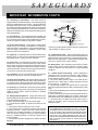
PR3200
NTSC
COMMERCIAL
SATELLITE
RECEIVER
Installation
And
Operation
Manual
Doc. No.OM2148N-1 REV. A
Date: 8/30/95
PICO MACOM INC. 12500 Foothill Blvd. • Lakeview Terrace, CA 91342 • (818) 897-0028 (800) 421-6511
SAFEGUARDS
IMPORTANT INFORMATION
Product Inspection
The lightning flash with arrowhead symbol, within an equilateral triangle, is intended to alert the user to the presence of
uninsulated "dangerous voltage" within
the product's enclosure that may be of
sufficient magnitude to constitute a risk of
electric shock to persons.
Inspect the equipment for shipping damage.
Should any damage be discovered, immediately file
a claim with the carrier.
Important
Safety Instructions
To insure proper installation and operation,
take a moment to read this guide before proceeding
with the installation. If you have any questions or
comments about the PR-3200 satellite receiver,
please contact your dealer or have him contact the
PICO MACOM Service Center at the phone numbers at the bottom of the page.
!
The exclamation point within an equilateral triangle is intended to alert the user to
the presence of important operating and
maintenance (servicing) instructions in the
literature accompanying the appliance.
WARNING:
TO REDUCE THE RISK OF FIRE OR ELECTRIC SHOCK, DO NOT
EXPOSE THIS APPLIANCE TO RAIN OR MOISTURE. DO NOT OPEN
THE CABINET, REFER SERVICING TO QUALIFIED PERSONNEL ONLY.
CAUTION:
TO PREVENT ELECTRIC SHOCK DO NOT USE THIS (POLARIZED) PLUG
WITH AN EXTENSION CORD RECEPTACLE OR OTHER OUTLET UNLESS
THE BLADES CAN BE FULLY INSERTED TO PREVENT BLADE EXPOSURE.
ATTENCION:
POUR PREVENIR LES CHOCS ELECTRIQUES, NE PAS UTILISER CETTE
FICHE POLARISEE AVEC UN PROLONGATEUR, UNE PRISE DE COURANT
OU UNE AUTRE SORTIE DE COURANT, SAUF SI LES LAMES PEUVENT
ETRE INSEREES A FOND SANS EN LAISSER AUCUNE PARTIE A
DECOUVERT.
1.
Read Instructions - All the safety and operating
instructions should be read before the appliance is operated.
2. Retain Instructions - The safety and operating instructions
should be retained for future reference.
3. Heed Warnings - All warnings on the appliance should be
adhered to.
4. Follow Instructions - All operating and user instructions
should be followed.
5. Cleaning - Unplug this appliance from the wall outlet before
cleaning. Use a damp cloth for cleaning. Do not use liquid
cleaners or aerosol cleansers.
6. Do Not Use Attachments - not recommended by the
manufacturer or they may cause hazards.
7. Water and Moisture - Do not use this product near water for
example, near a bathtub, washbowl, kitchen sink, laundry tub,
in a wet basement, or near a swimming pool - and the like.
8. Accessories - Do not place this product on an unstable cart,
stand, tripod, bracket, or table. The product may fall, causing
serious injury to a child or adult, and serious damage to the
appliance.
9. Ventilation - This video product should never be placed near
or over a radiator or heat register. This video product should not
be placed in a built-in installation such as a bookcase or rack
unless proper ventilation is provided or the manufacturer’s
instructions have been adhered to. Any slots or opening in the
cabinet are provided for ventilation. To ensure reliable operation of the video product and to protect it from overheating,
these openings must not be blocked or covered. The openings
should never be blocked by placing the product on a bed, sofa,
rug, or other similar surface.
1
PICO MACOM INC. 12500 Foothill Blvd. • Lakeview Terrace, CA 91342 • (818) 897-0028 (800) 421-6511
SAFEGUARDS
IMPORTANT INFORMATION CONT'D
10. Grounding or Polarization - This video product is
equipped with a polarized alternating - current line plug (a plug
having one blade wider than the other). This plug will fit into
the power socket only one way. This is a safety feature. If you
are unable to insert the plug full into the outlet, try reversing the
plug. If the plug should still fail to fit, contact your electrician to
replace your obsolete outlet. Do not defeat the safety purpose
of the polarized plug.
EXAMPLE OF ANTENNA GROUNDING ACCORDING TO
NATIONAL ELECTRICAL CODE INSTRUCTIONS CONTAINED
IN ARTICLE 810 - "RADIO AND TELEVISION
EQUIPMENT"
POW
ER
LINE
S
GROUND CLAMP
SERVICE ENTRANCE
CONDUCTORS
STANDOFF
INSULATORS b
MAST
11. Power Sources - This product should be operated only
from the type of power source indicated on the marking label.
If you are not sure of the type of power supplied to your home,
consult your appliance dealer or local power company.
12. Power-cord Protection - Power-supply cords should be
routed so they are not likely to be walked on or pinched by
items placed upon or against them. Pay particular attention to
cords and plugs, convenience receptacles, and the point
where they exit from the appliance.
13. Lightning - For added protection for this product during a
lightning storm, or when it is left unattended and unused for
long periods of time, unplug it from the wall outlet.
14. Power Lines - An outside antenna system should not be
located in the vicinity of overhead power lines, other electric
light or power circuits, where it can fall into such power lines or
circuits. When installing an outside antenna system, extreme
care should be taken to keep from touching such power lines
or circuits as contact with them may be fatal.
15. Overloading - Do not overload wall outlets and extension
cords as this can result in risk of fire or electric shock.
16. Object and Liquid Entry - Never push objects of any kind
into this product through openings as they may touch dangerous voltage points or short-out parts that could result in a fire
or electric shock. Never spill liquid of any kind on the product.
17. Servicing - Do not attempt to service this product yourself
as opening or removing covers may expose you to dangerous
voltage or other hazards. Refer all servicing to qualified
service personnel.
18. Damage Requiring Service - Unplug this product from
the wall outlet and refer servicing to qualified service personnel
under the following conditions:
a. When the power-supply cord or plug is damaged.
b. If liquid has been spilled, or objects have fallen into the
product.
c. If the product has been exposed to rain or water.
d. If the product does not operate normally by following the
operating instruction. Adjust only those controls that are
covered by the operating instructions. An improper adjustment may result in damage and will often require extensive
work by a qualified technician to restore the product to its
normal operation.
e. If the product has been dropped or the cabinet has been
damaged.
SERVICE
ENTRANCE
EQUIPMENT
ANTENNA
LEAD-IN WIRE
GROU
ND CL
AMPS
POWER SERVICE GROUNDING
ELECTRODE SYSTEM
(e.g. interior metal water pipe)
ANTENNA
c
DISCHARGE UNIT
TO EXTERNAL ANTENNA
TERMINALS OF PRODUCT
BONDING JUMPER
d
GROUND WIRE
GROUND CLAMPS
OPTIONAL ANTENNA GROUNDING ELECTRODE
DRIVEN 8 FEET (2.44M) INTO THE EARTH
IF REQUIRED BY LOCAL CODES. SEE NEC
SECTION 810 - 21(f).
f. When the product exhibits a distinct change in performance
- this indicates a need for service.
19. Replacement Parts - When replacement parts are
required, be sure the service technician has used replacement
parts specified by the manufacturer or have the same characteristics as the original parts. Unauthorized substitutes may
result in fire, electric shock or other hazards.
20. Safety Check - Upon completion of any service or repairs
to this product, ask the service technician to perform safety
checks to determine that the product is in proper operating
conditions.
21. Outdoor Antenna Grounding - Before attempting to
install this product, be sure the antenna or cable system is
grounded so as to provide some protection against voltage
surges and built-up static charges.
a. Use No.10 AWG (5.3mm ) copper, No.8 AWG (8.4mm
(aluminum, No.7 AWG (10mm ) copper-clad steel or bronze
wire or larger, as ground wire.
b. Secure antenna lead-in and ground wires to house with
stand-off insulators spaced from 4 feet (1.22m) to 6 feet (1.83m)
apart.
c. Mount antenna discharge unit as close as possible to where
lead-in enters house.
d. A driven rod may be used as the grounding electrode where
other types of electrode systems do not exist. Refer to the
National Electrical Code, ANSI/NFPA 70-1984 for information.
e. Use jumper wire not smaller than No.6 AWG (13.3mm )
copper or equivalent, when a separate antenna grounding
electrode is used.
NOTE TO THE CATV SYSTEM INSTALLER:
THIS REMINDER IS PROVIDED TO CALL THE CATV
SYSTEM INSTALLER’S ATTENTION TO ARTICLE 820 22 OF THE NEC THAT PROVIDES GUIDELINES FOR
PROPER GROUNDING AND, IN PARTICULAR, SPECIFIES THAT THE CABLE GROUND SHALL BE CONNECTED TO THE GROUNDING SYSTEM OF THE BUILDING, AS CLOSE TO THE POINT OF CABLE ENTRY AS
PRACTICAL.
PICO MACOM INC. 12500 Foothill Blvd. • Lakeview Terrace, CA 91342 • (818) 897-0028 (800) 421-6511
2
DESCRIPTIONS
T
he PR-3200 is an economic descrambler
compatible commercial satellite receiver
designed for SMATV systems. The unit has
been tested by General Instruments to meet all
VideoCipher® II performance requirements. The
PR-3200 provides three video outputs configured
to interface with all known scrambling systems.
The standard 950 to 1750 MHz tuning range of
the PR-3200 allows direct compatibility for
international CCIR standards.
Technical Operation
RF Input The PR-3200 receives either CBand or Ku-Band signals from a 950-1450 MHz
LNB or a 950-1750 MHz LNB. Typical installations using 60 dB gain LNB's have -25 dBm
available a t the output of the LNB. The PR-3200
will operate at input levels ranging from -30 dBm
to as low as -60 dBm. A front panel signal strength
meter is provided. At full IF gain; a meter reading
of 2 corresponds to a -60 dBm input, a reading of
8 corresponds to an input of -30 dBm.
70 MHz IF The selected RF input signal is
converted to a 70 MHz Intermediate Frequency
(I.F.). The PR-3200 comes with a short I.F. jumper
cable that must be installed between the "I.F.
OUT" and the "I.F. IN" connectors on the back of
the receiver. Terrestrial interference traps may be
inserted in the loop should microwave interference
be encountered.
LNB Power Most commercial headend
systems consist of several receivers and
modulators. The PICO MACOM Satellite Signal
Processor SSP-10 provides the dual LNB power
and the amplified power divider for such
applications. The PR-18DC external power
supply is also available for single receiver
applications. The PR-18DC power cable plugs
directly into the back of the PR-3200 to provide
+18 VDC power for the LNB.
H/V Switching The PR-3200 provides
automatic H/V switching.
Channel Selection
is phase locked loop
controlled with a digital display of channel
numbers.The receiver comes factory tuned for
standard 24 channel C-Band operation.
Ku Band Operation The PR-3200 may also
be used for Ku band signals by use of the video
invert rear panel switch.
Audio Subcarrier selection is made from the
front panel in one of two ways. A preset PLL
tuned 6.8MHz demodulator or variable tuned
5.0MHz to 8.0MHz demodulator can be selected.
Outputs
Three video outputs are provided on
the rear of the PR-3200. Video and audio output
levels are factory set for C-band operation. Level
controls are accessible from bottom of unit. One
video output is filtered and clamped for
unscrambled programming. The composite video
output is de-emphasized, un-clamped and unfiltered for VideoCipher® operation. The MAC
descrambler compatible flat video output is
unclamped, un-filtered and has no de-emphasis.
3
PICO MACOM INC. 12500 Foothill Blvd. • Lakeview Terrace, CA 91342 • (818) 897-0028 (800) 421-6511
SPECIFICATIONS
IF Input
Video
Input Impedance: ................................... 75 Ohm
Impedance: ................................................ 75 ohm
Input Frequency: .................... 950-1450 MHz or
...................................................... 950-1750 MHz
Video Output Level: ............................ Adjustable
Input Level: ................................. -30 to -60 dBm
IF Frequency: ......................................... 70 MHz
AFC Range: @ 70 MHz ......................... ±4 MHz
Fine Tuning: @ 70 MHz ............ ±8 MHZ typical
IF Bandwidth:@ -3 dB .......................... 27 MHz
Static Threshold: ......................................... 7 dB
Intermodulation: ....................................... -40 dB
Preset for 10.75 MHz deviation ...................... 1.0 Vp-p
Video S/N Ratio: ........................ 52 dB weighted
........................................................ @ 14 dB CNR
Video Polarity: ............ Switchable Negative Sync
Differential Gain: .................... 5% p-p maximum,
at 10% to 90% APL
Differential Phase: ............... 5 deg p-p maximum,
at 10% to 90% APL
Spurious Rejection: .................................. -40 dB
Audio
Clamped, Filtered, DeEmphasized
Output
Subcarrier Frequency: ................. 6.8 MHz fixed
....................................... or 5 - 8.5 MHz (tunable)
Bandwidth: ±1.0dB .................... 50 Hz - 4.2 MHz
Impedance: ............................................ 600 ohm
De-emphasis: ............................. CCIR REC 405-1
Clamping: .................................................... 40 dB
Freq. Response: 50 Hz - 15 kHz ............... ±2.0 dB
Harmonic Distortion:
@ 75 kHz deviation ...................... 2% maximum
Video Monitor
Impedance: ................................................ 75 ohm
Output Level:
@ 600 ohm load ......................... 1Vp-p minimum
Output Level: ............................................. 1 Vp-p
De-emphasis: ............................. 75 microseconds
Composite Video
General
Input Power: ................ 108-125 VAC 50/60 Hz,
................................................... 40 watts nominal
V/H Control: .............................. +5VDC/-5VDC
Frequency Response:
30 Hz - 3.58 MHz ........................... ±0.5 dB
3.58 MHz-4.2 MHz ........................ ±1.0 dB
De-emphasis: ............................. CCIR REC 405-1
LNB Supply Voltage: .............. Optional external
..................................... +18 Vdc Supply PR-18DC
Operating Temperature: ......... 0 to 40 degrees C
Flat Video
Mechanical Dimensions: ........... 19" x 1.75" x 8"
Bandwidth: ±1.0dB ............... 15.0 Hz to 10.5 MHz
4
PICO MACOM INC. 12500 Foothill Blvd. • Lakeview Terrace, CA 91342 • (818) 897-0028 (800) 421-6511
FRONT PANEL
FRONT & REAR PANEL
1
2
3
3
4
5
6
7
PR-3200 SATELLITE RECEIVER
.75MHz
SET
CATV SERIES
1.
2.
3.
MODE
+
–
0 2 4 6 8 10
SIGNAL STRENGTH
4.
SET KEY:
The "SET" key is for programming the video
I.F. frequency and the audio sub-carrier
frequency.
+/- Keys:
These keys are used for changing, up or down,
the channels, I.F. frequency and audio modes.
C-Band
14
.25MHz
MODE KEY:
The "MODE" key selects the audio mode:
6.8MHz preset or 5.0MHz to 8.MHz tunable.
Channel I.F.
MONITOR
.50MHz
5.
6.
7.
SEVEN SEGMENT DISPLAY:
The display indicates the channel number. I.F.
frequency and audio for both C-band and Ku
band transponders.
LED's:
The LED's indicate changes in the I.F. frequency
in 250KHz increments.
MONITOR:
The front panel "F" connector provides a clamped
video output.
SIGNAL STRENGTH:
The meter provides a relative measure of RF
input to the receiver.
Ku-Band Channel I.F.
C-Band
Ku-Band
Display
MHz
MHz
MHz
Display
MHz
MHz
MHz
1
2
3
4
5
6
7
8
9
10
11
12
1430
1410
1390
1370
1350
1330
1310
1290
1270
1250
1230
1210
3720
3740
3760
3780
3800
3820
3840
3860
3880
3900
3920
3940
12180
12160
12140
12120
12100
12080
12060
12040
12020
12000
11980
11960
13
14
15
16
17
18
19
20
21
22
23
24
1190
1170
1150
1130
1110
1090
1070
1050
1030
1010
990
970
3960
3980
4000
4020
4040
4060
4080
4100
4120
4140
4160
4180
11940
11920
11900
11880
11860
11840
11820
11800
11780
11760
11740
11720
5
PICO MACOM INC. 12500 Foothill Blvd. • Lakeview Terrace, CA 91342 • (818) 897-0028 (800) 421-6511
REAR
PANEL
FRONT & REAR PANEL
8
9
10
11
12
13
14
FLAT
VIDEO OUT
COMP
VIDEO OUT
VIDEO
15
16
17
18
600VA MAX
IN
950-1750
MHz INPUT
70 MHz
IF LOOP
OUT
INV NORM
3/8 A 250V
120V
60 Hz 0.3A
AUDIO
FUSE
LNB
Power
IF GAIN
19
H
B/MAC
V
VIDCIP
20
AC ADAPTOR
PLUG IN CLASS 2 TRANSFORMER
UL
LISTED
69NO
E97199
0694
MODEL: D6-1007
INPUT:120V 60Hz 25W
OUTPUT: 18VDC 250 mA
8.
9.
RF Input:
Input connection from C-band or Ku-band
LNB. ( 950 to 1750 MHz). Also provides
+18VDC output if PS-18DC is connected
to 10 LNB Power.
LNB Power:
This 3.5mm RCA jack accepts the optional
PS-18DC LNB power supply voltage.
10. I.F. Loop:
The 70 MHz IN and OUT connectors loop
the un-filtered tuner output for possible
terrestrial interference filtering. Normally
the short jumper is connected and the IF
gain is set to maximum (fully CW).
11. Video Invert:
The Normal/Invert switch controls the
video polarity of the the output amplifiers.
Toggling the switch affects all three video
outputs.
12. Flat Video Out:
A one volt peak to peak unfiltered,
unclamped and non de-emphasized signal
is provided for MAC type decoders.
13. Comp Video Output:
14. Video:
A one volt peak to peak composite CCIR
405-1, 525 line de-emphasized, filtered and
clamped video signal is provided for
unscrambled programming.
15. Audio:
Standard RCA connection to feed either a
descrambler or a SMATV modulator
16. H/V Electronic A/B Terminal:
A switching +5/-5 VDC voltage is provided
between the push terminals to control a
PICO MACOM ABE-C/Ku H/V switch.
17. Fuse:
Replace this fuse with only one of the same
rating as indicated on the chassis.
18. Convenience Outlet:
The AC outlet is capable of delivering up to
600 watts of AC power.
19. Power Cord:
Connect to 108 to 125 VAC, 50/60 Hz
electrical outlet.
20. PR-18DC:
Optional power supply to power LNB.
A one volt peak to peak composite CCIR
405-1 525 line de-emphasized, unfiltered
and unclamped video signal is provided for
the VideoCipher®II decoders.
6
PICO MACOM INC. 12500 Foothill Blvd. • Lakeview Terrace, CA 91342 • (818) 897-0028 (800) 421-6511
INSTALLATION
LNB
POWERING
METHODS
HORIZONTAL
V
E
R
T
I
C
A
L
+
+
+
+
220VAC
50Hz 25W
VERT.
TO
LNB
HIGH
OUTPUT
1
2
3
4
CAUTION
5 OUTPUTS
RISK OF ELECTRIC SHOCK
DO NOT OPEN
HORZ.
!
+
+
SSP-10
+
+
70 MHz
IF LOOP
IN
950-1750
MHz INPUT
OUT
FLAT
VIDEO OUT
COMP
VIDEO OUT
B/MAC
VIDCIP
INV NORM
+
3/8 A 250V
VIDEO
600VA MAX
AUDIO
LNB
Power
120VAC
60Hz 10W
FUSE
H
IF GAIN
V
PR3200
PR3200
DUAL FEED
HORN
PR-18DC
C
K
U
AC ADAPTOR
To Receiver
Tru Spec
™
®
ELECTRONIC SATELLITE SWITCH
PLUG IN CLASS 2 TRANSFORMER
UL
LISTED
69NO
E97199
G
N
D
0694
MODEL: D6-1007
INPUT:120V 60Hz 25W
ABE-C/Ku
Ku
OUTPUT: 18VDC 250 mA
+
+
IN
950-1750
MHz INPUT
V
70 MHz
IF LOOP
OUT
FLAT
VIDEO OUT
COMP
VIDEO OUT
B/MAC
VIDCIP
INV NORM
+
3/8 A 250V
VIDEO
AUDIO
LNB
Power
600VA MAX
120VAC
60Hz 10W
FUSE
IF GAIN
H
V
PR3200
7
PICO MACOM INC. 12500 Foothill Blvd. • Lakeview Terrace, CA 91342 • (818) 897-0028 (800) 421-6511
INSTALLATION
D E S C RAM B L E R & M O D U LAT O R I N T E R FAC E S
PR-3200
70 MHz
IF LOOP
IN
950-1750
MHz INPUT
OUT
600VA MAX
FLAT
VIDEO OUT
COMP
VIDEO OUT
INV NORM
VIDEO
120V
60 Hz 0.3A
3/8 A 250V
AUDIO
FUSE
LNB
Power
H
B/MAC
V
VIDCIP
POWER
0.5 AMP
FUSE
OFF
TB2
LEFT
VIDEOCIPHER II
OUT
IN
MONO
OUT
IN
ON
TB1
RIGHT
OUT
IN
1 2 3 4 5 6 7 8 9 10 1112
AUDIO
ADJ
L
M
R
L UTIL OUT
C
A S A
G E N CLK DATA O N
M O
C R G
BYPASS
G
A
I
N
1 2 3 4 5 6 7 8 9
B
I
A
S
CHASSIS
GND
GND
J4
J3
J2
OUT
BYPASS
IN
LOOP
THRU
G
A
I
N
J1
IN
VIDEO
GND
SHIELD TO NEG. CENTER CONDUCTOR TO POS. +
+
+
VIDEO IN
+
RF
OUT
+
120VAC
60Hz 10W
AUDIO IN
PCM55
Modulator
+
+
+
600VA MAX
THE PR-3200 WITH A VIDEOCIPHER®*
4. Connect the PR-3200 to the VIDEOCIPHER® as follows:
a. "COMP VIDEO OUT" output to J-1 of the
VIDEOCIPHER®.
b. "VIDEO" output to J-3 of the VIDEOCIPHER®.
c. Modulator video input to J-4 of the
VIDEOCIPHER®.
d. Audio output, monaural: connect "AUDIO" to
terminals 7 and 8 of VIDEOCIPHER®'s TB2.
5. Connect appropriate TB2 output to either a modulator
or a stereo processor.
Note: When using the VIDEOCIPHER®, be sure that the
AGC is adjusted to 4 V.D.C. after warm up.
1. Carefully attach the receiver to the rack and plug the
six foot cord into a grounded 115 VAC power receptacle.
2. Install the short I.F. jumper cable between the "I.F.
out" and the "I.F. In" connectors on the rear of the
receiver
3. Connect the R.F. lead coming from the LNB to the
"R.F. In" connector . Monitor the signal level meter on
the front panel . A meter reading between 2 and 8 is
required. The meter is factory calibrated for C-band transmissions. A reading of 2 correlates to an input of -60 dBm.
A reading of 8 correlates to an input of -30 dBm.
*Videocipher is a registered trademark of General Instruments Corp.
+
+
IN
950-1750
MHz INPUT
70 MHz
IF LOOP
OUT
FLAT
VIDEO OUT
COMP
VIDEO OUT
B/MAC
VIDCIP
INV NORM
+
3/8 A 250V
VIDEO
AUDIO
LNB
Power
600VA MAX
120VAC
60Hz 10W
FUSE
IF GAIN
H
V
PR3200
+
+
RF OUT
AUDIO IN
VIDEO IN
+
CAUTION
RISK OF ELECTRIC SHOCK
DO NOT OPEN
600VA MAX.
+
120VAC
60Hz 10W
CAUTION: TO REDUCE THE RISK OF ELECTRIC SHOCK,
DO NOT REMOVE COVER (OR BACK)
+
+
PCM55
NO USER-SERVICEABLE PARTS INSIDE
REFER SEVICING TO QUALIFIED SERVICE PERSONNEL
+
TO TV
PICO MACOM INC. 12500 Foothill Blvd. • Lakeview Terrace, CA 91342 • (818) 897-0028 (800) 421-6511
8
PROGRAMMING
1. Plug the AC cord to an AC outlet and turn
on the receiver.
2. If the receiver has not been pro-grammed
for the last channel, the display shows "1"
which indicates CH.1.
3. Normally, the receiver has been preset
and factory programmed. See the preset
Channel Table attached.
4. Select the channel number to be programmed by using "+"/"-" keys
Video I.F. Frequency:
5. Start programming by pressing “SET”
key. The first pressing of the “SET” key is
for programming the video i.f. frequency.
The display shows the reading of the i.f.
frequency. Usually, the frequency shown is
the preset frequency of this channel.
6. Program the i.f. frequency by using the
“+”/”-” keys.
7. Press “+”/”-” keys once at a time, the
frequency moves up/down in increments of
250KHz. The LED indicator on the right
side of the main display indicates the changes.
The display of the change would be carried
to the main display every 1MHz.
8. Continue to press the “+”/”-” for more
than one second. The rate of frequency
increment/decrement will be sped up/down
for faster programming.
Audio Mode/
Audio Carrier Frequency
9. Press the "SET" key again. The second
pressing of the "SET" is for programming
the audio sub-carrier frequency.
10. Normally, the audio mode is preset in
MONAURAL and the audio sub-carrier.
frequency is preset at 6.80MHz and is the
only mode that is currently operational. Disregard modes 2, 3, & 4.
MODE DISPLAY STATUS
1.
A.6.80
MONO/6.80MHZ/
Wide Band
11. Use “MODE” key to select AUDIO
MODE 1.
12. Use the "+"/"-" key to program the audio
sub-carrier frequency.
13. Press "+"/"-" key. Each time the frequency moves up/down 10KHz.
14. Keep pressing the "+'/"-" key for more
than one second. The rate of frequency increment/decrement will be speed up/down for
faster programming.
15. Press the set key again. This third pressing of the "SET" key is to program the polarity. and LNB inputs. Currently, the only
mode that is operational is MODE 1. Audio
Sub-carriers from 5.0MHz to 8.0MHz can be
accessed in this mode. Disregard MODES 2,
3 & 4.
MODE DISPLAY POLARTIY LNBINPUT
1.
U. 1.
Vertical
1.
Completion of Programming:
In SMATV application, automatic LAST
channel set-up may be reqiired accidental
power failure. The procedure for LAST channel programming are as follows.
1. Select the number of the LAST channel.
to used by using "+"/"-" keys.
2. Press "SET" key 4 times, and confirm all
of the parameters as they are going through
the display.
3. As soon as the display goes back to channel
display, the LAST channel programming is
completed.
9
PICO MACOM INC. 12500 Foothill Blvd. • Lakeview Terrace, CA 91342 • (818) 897-0028 (800) 421-6511
PCB CONTROLS
CLAMPED VIDEO
ADJUST
COMPOSITE VIDEO
ADJUST
BMAC VIDEO
ADJUST
9
10
PICO MACOM INC. 12500 Foothill Blvd. • Lakeview Terrace, CA 91342 • (818) 897-0028 (800) 421-6511
WARRANTY
FIVE YEAR LIMITED WARRANTY
P
ico Macom, Inc.
warrants to the
original purchaser
this product shall be
free of defects in
material
and
craftsmanship with only the
limitations or exclusions set out
below.
During the warranty period Pico
Macom Inc. or an authorized Pico
Macom service facility will provide
free of charge, the parts and labor
necessary to correct defects in
material and workmanship.
WARRANTY DURATION
This warranty shall terminate five
years from the original date of
purchase of the product or at a time
the product is:
1. Misused or damaged due to
neglect or improper installation
2. Modified
3. Repaired by someone other
than the warrantor
4. Sold by the original purchaser
STATEMEN OF REMEDY
To obtain warranty service,
contact the salesperson where the
product was obtained. You will be
issued a Return Authorization (RA)
number which will be used to track
your product.
11
Be prepared to provide:
1. The model number and channel
number of the product
2. The date of purchase
3. A specific identification of the
problem
Deliver the products to Pico Macom
Inc. or ship the products in the original
packing material at the address at the
bottom of the page.
Include
satisfactory evidence of the date of
purchase.
Products will not be accepted by
Pico Macom Inc. without the RA
number clearly indicated on the
shipping label.
The foregoing constitutes the Pico
Macom, Inc. entire obligation with
respect to this product and the original
purchaser and any user or owner shall
have no other remedy and no claim
for incidental or consequential
damages. Some states do not allow
limitations on how long an implied
warranty lasts or do not allow the
exclusions or limitation of incidental
or consequential damages, so the
above limitation and exclusion may
or may not apply to you.
This warranty gives you specific
legal rights, and you also have rights
which vary from state to state.
10
PICO MACOM INC. 12500 Foothill Blvd. • Lakeview Terrace, CA 91342 • (818) 897-0028 (800) 421-6511
NOTES
PICO MACOM INC. 12500 Foothill Blvd. • Lakeview Terrace, CA 91342 • (818) 897-0028 (800) 421-6511
NOTES
PICO MACOM INC. 12500 Foothill Blvd. • Lakeview Terrace, CA 91342 • (818) 897-0028 (800) 421-6511
NOTES
PICO MACOM INC. 12500 Foothill Blvd. • Lakeview Terrace, CA 91342 • (818) 897-0028 (800) 421-6511
PICO MACOM INC. 12500 Foothill Blvd. • Lakeview Terrace, CA 91342 • (818) 897-0028 (800) 421-6511