1
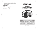
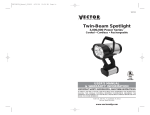
VEC128SL_ManualEN_092605
9/26/05
9:20 AM
Page 1
VEC128SL
SPORT SPOT ® LANTERN COMBO
CORDLESS • RECHARGEABLE
PATENT No D432,692
AND OTHER PATENTS PENDING
USER'S MANUAL &
WARRANTY INFORMATION
IMPORTANT SAFETY INFORMATION, SAVE THESE INSTRUCTIONS
TO REDUCE THE RISK OF INJURY, USER MUST READ AND UNDERSTAND
THIS INSTRUCTIONAL MANUAL. THIS MANUAL CONTAINS IMPORTANT
INFORMATION REGARDING THE OPERATION AND WARRANTY OF THIS
PRODUCT. PLEASE RETAIN FOR FUTURE REFERENCE.
© 2005 VECTOR MANUFACTURING
4140 SW 30TH AVE.
FT. LAUDERDALE, FL 33312
4140 S.W. 30th Ave., Ft. Lauderdale, FL 33312
Toll Free: (866) 584-5504
www.vectormfg.com
VEC128SL_ManualEN_092605
9/26/05
9:20 AM
Page 3
ONE YEAR LIMITED WARRANTY PROGRAM
This limited warranty program is the only one that applies to this product, and it sets forth all the
responsibilities of Vector Manufacturing, regarding this product. There is no other warranty, other than
those described herein. Any implied warranty of merchantability or fitness for a particular purpose on
this product is limited in duration to the duration of this warranty.
This Vector Manufacturing product is warranted, to the original purchaser only, to be free of defects in
materials and workmanship for one year from the date of purchase without additional charge. The
warranty does not extend to subsequent purchasers or users. Manufacturer will not be responsible for
any amount of damage in excess of the retail purchase price of the product under any circumstances.
Incidental and consequential damages are specifically excluded from coverage under this warranty.
This product is not intended for commercial use. This warranty does not apply to damage to units from
misuse or incorrect installation/connection. Misuse includes wiring or connecting to improper polarity
power sources.
RETURN/REPAIR POLICY: Defective products may be returned to manufacturer. Any defective product
that is returned to manufacturer within 30 days of the date of purchase will be replaced free of charge.
If such a product is returned more than 30 days but less than one year from the purchase date,
manufacturer will repair the unit or, at its option, replace it, free of charge.
If the unit is repaired, new or reconditioned replacement parts may be used, at manufacturer’s option.
A unit may be replaced with a new or reconditioned unit of the same or comparable design. The
repaired or replaced unit will then be warranted under the terms of the remainder of the warranty
period. The customer is responsible for the shipping charges on all returned items. During the warranty
period, manufacturer will be responsible for the return shipping charges to the customer in the United
States.
LIMITATIONS: This warranty does not cover accessories, such as charging adapters, bulbs, fuses and
batteries, damage or defects resulting from normal wear and tear (including chips, scratches, abrasions,
discoloration or fading due to usage or exposure to sunlight), accidents, damage during shipping to our
service facility, alterations, unauthorized use or repair, neglect, misuse, abuse, failure to follow
instructions for care and maintenance, fire, flood and Acts of God.
If your problem is not covered by this warranty, call our Technical Support Department at (954) 5844446 or toll free at (866) 584-5504 for general repair information and charges if applicable. You may
also contact us through our website at www.vectormfg.com.
STATE LAW RIGHTS: This warranty gives you specific legal rights. Some states do not allow limitations
on how long an implied warranty lasts or the exclusion or limitation of incidental or consequential
damages, so the exclusions or limitations stated herein may not apply. This warranty gives the purchaser
specific legal rights; other rights, which vary from state to state, may apply.
TO REQUEST WARRANTY SERVICE FOR THIS PRODUCT: Contact Technical Support by telephone, fax
or mail (see below). We suggest that you keep the original packaging in case you need to ship the unit.
When returning a product, include your name, address, phone number, dated sales receipt (or copy)
and a description of the reason for return and product serial number. After repairing or replacing the
unit, we will make every effort to return it to you within four weeks.
WARRANTY ACTIVATION: Please complete Warranty Activation Card and mail to Vector
Manufacturing. Enter “VEC128SL” as Model and “SPORT SPOT® LANTERN COMBO” as Product Type.
All Vector products must be registered within 30 days of purchase to activate this warranty. Mail the
completed registration form, along with a copy of the original sales receipt, to:
ATTN.: CUSTOMER SERVICE
4140 SW 30th Ave., Ft. Lauderdale, FL 33312
• TOLL FREE: (866 ) 584-5504 • FAX: (954) 584-5556 •
WARRANTY IS NON-TRANSFERABLE.
BD091905
© 2005 VECTOR MANUFACTURING
MADE IN CHINA
VEC128SL_ManualEN_092605
9/26/05
9:20 AM
Page 5
9.1 BATTERY REMOVAL PROCEDURE
CAUTIONS:
1. Press the tab on the lower part of the Battery Compartment Cover while
lifting the cover.
2. Fully remove the cover and set it aside.
3. Carefully move the battery towards the opening of the compartment.
4. Using a long nose pliers, carefully rock each spade terminal and remove
them from the Battery Spade Lug Terminals. Note the colors of the attached
wires and to which terminal they were connected.
5. Fully remove the battery and set it aside.
6. Follow Safe Battery Disposal instructions.
• DO NOT SUBMERGE IN WATER.
• Do not recharge with other than supplied AC and
DC Recharge Adapters
• Do not overcharge battery
• Do not operate lights while recharging—this can cause damage
to the unit or charger
• This spotlight produces high levels of heat when
operating—DO NOT TOUCH THE SPOTLIGHT LENS
WHEN THE SPOTLIGHT IS ON
• Keep spotlight lens away from combustible materials when
spotlight is On
• This light is not a toy—keep away from children
9.2 BATTERY INSTALLATION PROCEDURE
1. Partially insert the new battery in the compartment in the same position as the
old battery.
2. Using long nose pliers, attach the Spade Connectors to their respective
Battery Spade Terminals. Check to ensure they are fully connected.
3. Push battery back into compartment.
4. Replace cover and slide downward until the tab snaps into place.
5. Momentarily check operation of the spotlight and lantern for proper operation.
6. Recharge the battery using either the AC or DC Recharge Adapter.
10. SAFE BATTERY DISPOSAL
Contains a maintenance-free, sealed, non-spillable, lead acid battery. This battery
is fully recyclable and should be accepted at any location that accepts common
automotive starter batteries. County or municipal recycling drop-off centers, scrap
metal dealers and retailers who sell automotive replacement lead acid starter
batteries. For more information on recycling this battery, call toll-free (877) 2887722
BATTERY DISPOSAL WARNINGS
• Do not dispose of the battery in fire as this may result in an explosion
• Before disposing the battery, protect exposed terminals with heavy-duty
electrical tape to prevent shorting (shorting can result in injury or fire)
• Do not expose battery to fire or intense heat as it may explode
CONTENTS
1.
INTRODUCTION . . . . . . . . . . . . . . . . . . . . . . . . . . . . . . . .1
2.
FEATURES . . . . . . . . . . . . . . . . . . . . . . . . . . . . . . . . . . . . .2
3.
OPERATION . . . . . . . . . . . . . . . . . . . . . . . . . . . . . . . . . . . .2
4.
RECHARGE . . . . . . . . . . . . . . . . . . . . . . . . . . . . . . . . . . . .2
4.1 AC Recharge . . . . . . . . . . . . . . . . . . . . . . . . . . . . . . . .3
4.2 DC Recharge . . . . . . . . . . . . . . . . . . . . . . . . . . . . . . . .3
5.
MAINTENANCE/PARTS REPLACEMENT . . . . . . . . . . . . . . . .3
6.
SPOTLIGHT BULB REPLACEMENT . . . . . . . . . . . . . . . . . . . . .3
6.1 SPOTLIGHT Bulb Removal . . . . . . . . . . . . . . . . . . . . . . .4
6.2 Spotlight Bulb Installation . . . . . . . . . . . . . . . . . . . . . . . .4
7.
LANTERN TUBE REPLACEMENT . . . . . . . . . . . . . . . . . . . . . .5
7.1 Fluorescent Tube Removal . . . . . . . . . . . . . . . . . . . . . . .5
7.2 Fluorescent Tube Installation . . . . . . . . . . . . . . . . . . . . . .6
8.
FUSE REPLACEMENT . . . . . . . . . . . . . . . . . . . . . . . . . . . . .6
9.
BATTERY REPLACEMENT . . . . . . . . . . . . . . . . . . . . . . . . . . .6
9.1 Battery Removal . . . . . . . . . . . . . . . . . . . . . . . . . . . . . .7
9.2 Battery Installation . . . . . . . . . . . . . . . . . . . . . . . . . . . .7
10.
SAFE BATTERY DISPOSAL . . . . . . . . . . . . . . . . . . . . . . . . . .7
11.
SPECIFICATIONS . . . . . . . . . . . . . . . . . . . . . . . . . . . . . . . .7
11. SPECIFICATIONS
Spotlight Bulb
Lantern Tube
Battery
Fuse
H-3 Series, 6 volt, proprietary
13 Watt, Twin U Tube Fluorescent, proprietary
Maintenance free, sealed lead acid 6 volt, 6 Amp Hour
.5 Ampere
WARRANTIES
7
VEC128SL_ManualEN_092605
9/26/05
9:20 AM
Page 7
7.2. FLUORESCENT TUBE INSTALLATION
1. INTRODUCTION
Congratulations on purchasing the Vector Sport Spot Lantern, an advanced design
combination spotlight and lantern. It instantly converts use from a powerful spotlight
to a soft, long-lasting area light. See Figure 1A and 1B. It uses a powerful
proven-technology, rechargeable, sealed lead acid battery that allows for years of
dependable use, recharge after recharge. It was designed from the ground up to
be the most versatile and practical light for travel, camping, picnicking, tailgate
parties and boating. The Sport Spot Lantern gives you the kind of light you need,
when and where you need it.
1. Make sure that the Lantern Switch is Off.
2. Press the new fluorescent tube’s base into the Tube Socket Assembly.
3. Replace the Tube Socket Assembly so that the two Support Rods pass
through the assembly and it is fully seated against the clear plastic dome.
4. Replace the two nuts and tighten (clockwise) so that the tube assembly is snug.
5. Screw on (clockwise) the End Cap until it is snug.
6. Test the fluorescent tube for proper operation by reconnecting the battery
and turning On the Lantern switch.
8. FUSE REPLACEMENT
FIGURE 1A
FIGURE 1B
The fuse is located inside the DC plug. (See Figure 5 for fuse replacement.)
Make sure the DC Recharge connector is disconnected from the Sport Spot Lantern.
FIGURE 5
FLANGE
°
SPOTLIGHT ON/OFF
LANTERN SWITCH
RECHARGE LEDS
CONTACT
SPRING
PLUG
FUSE
FUSE REPLACEMENT PROCEDURE
1.
2.
3.
4.
5.
6.
Unscrew (counterclockwise) the flange from the DC plug.
Remove the flange, contact and fuse from the plug assembly.
Replace fuse with a .5 amp fuse of same type and size.
Place the center contact in the flange.
Replace the center contact and flange on the DC plug.
Tighten (clockwise) until the flange is fully seated.
DO NOT OVERTIGHTEN FLANGE!
9. BATTERY REPLACEMENT
Two recharge adapters are supplied with the Sport Spot Lantern. It is rechargeable
from either a DC cigarette lighter type 12 volt DC socket (accessory socket) or from
any 120 volt 60 Hz AC receptacle. 12 volt DC power is available from most
vehicles, boats, jump starters and portable battery packs. Vector has a variety of
portable power products that may be considered as companions to your Sport Spot
Lantern. Contact Vector for additional information.
The battery is contained in a compartment in the base of the unit. A plate must be
removed to gain access to the battery. Figures 5A and 5B show access to the
battery compartment.
FIGURE 5A
FIGURE 5B
BATTERY
COMPARTMENT
COVER
SWITCH
AC/DC
RECHARGE
BARREL
RECEPTACLE
1
TAB
SPADE
CONNECTOR
SPADE
LUG
TERMINALS
SPADE CONNECTOR
BATTERY
6
VEC128SL_ManualEN_092605
9/26/05
9:20 AM
Page 9
7. LANTERN TUBE REPLACEMENT
2. FEATURES
The Lantern fluorescent tube is mounted on a socket assembly. Power is sent to the
tube socket through the two support rods. It is very important to make sure the
Lantern switch is turned OFF before removing the end cap. If there are any doubts
about the ON/OFF switch being Off, then refer to the Battery Removal section and
disconnect the battery before removing the end cap.
WARNING:
FLUORESCENT TUBES OPERATE WITH HIGH VOLTAGE.
DO NOT REMOVE END CAP UNLESS POWER IS OFF
AND THE BATTERY IS DISCONNECTED. SEE SECTION 9
•
•
•
•
See Figure 4 for Fluorescent Tube Replacement
FIGURE 4
3
1
4
•
•
•
•
•
•
•
5
2
1,000,000 Power Series™ Spotlight
Powerful replaceable H-3 Series 6 volt quartz halogen bulb in spotlight
Powerful replaceable 13 watt fluorescent U-shaped twin tube in lantern
Head swivels 90 degrees for soft, 360 degree area lighting
Rubber safety guard protects spotlight
Recharging LED and battery FULL LED
Recharges from standard North American Standard 120 volt AC,
60 Hz, receptacle
Recharges from 12 volt DC accessory socket
Three way switch - Spotlight, Off and Lantern
Comfortable handgrip
Stable base prevents tip over in any head position
NOTE:
This unit is shipped in a partially charged state. Charge unit using either
AC or DC method until the green LED lights. Charge after each use. Initial
charge should be for 12 hours.
3. OPERATION
6
1.
2.
3.
4.
5.
6.
DOME
TWIN TUBE FLUORESCENT
TUBE SOCKET ASSEMBLY
NUTS
END CAP
SUPPORT RODS
The swivel action of the unit keeps the lamp head securely in position for use while
carrying or while on tabletop. The range of swivel motion is greater than 90
degrees with five locking positions. The spotlight position (upright) focuses light
straight ahead. The lantern position (spotlight tilted forward 90 degrees) floods
light in a 360-degree pattern for reading, cooking and many other uses. A
three-position Power Switch (Spotlight, Off, Lantern) controls on/off operation of
both lights. The switch is protected by a flexible covering that protects it from dust,
dirt and moisture. This ensures reliability and extends the life of the switch. The
spotlight can be continuously lit for up to 20 minutes on a full battery charge; the
lantern can be lit for up to four hours on a full battery charge.
4. RECHARGE
7.1 FLUORESCENT TUBE REMOVAL
1. Make sure that the Power Switch is Off AND the battery is disconnected.
2. Remove the set screw from the end cap - item #5.
3. Rest the unit on a secure tabletop.
4. Position the head to be in the Spotlight position.
5. Unscrew (counter clockwise) the End Cap and set aside.
6. Unscrew (counter clockwise) the two nuts from the two support rods and set
them aside.
7. Slide the Tube Socket assembly away from the head and remove it from
the two support rods.
8. Set it on a stable work surface like a table, bench,etc.
9. Grasp the Tube Socket and push on the fluorescent tube base to disconnect
the tube from the socket.
10. Do not allow the tube to drop.
11. Follow local procedures for safe fluorescent tube disposal.
5
All batteries lose charge over time, especially when they are warm. Frequent
battery recharges will extend battery life. AC recharge is recommended every two
months, when not in frequent use. Use the AC recharge adapter and charge until
battery is full. AC and DC recharge connections are through a heavy-duty barrel
receptacle at the lower rear of the unit. (See figure 5A) Two LED indicators display
the status of recharge. Continue recharge operation until the two LEDS are equally
bright. (See Figure 1A.)
2
VEC128SL_ManualEN_092605
9/26/05
9:20 AM
Page 11
AC AND DC RECHARGE ADAPTERS
FIGURE 2A
FIGURE 2B
SPOTLIGHT BULB REMOVAL/INSTALLATION
4
5
3
FIGURE 3
2
DC RECHARGE
ADAPTER
AC RECHARGE
ADAPTER
6
7
FUSED DC PLUG
1
8
BARREL CONNECTOR
4.1 AC RECHARGE
The AC Recharge adapter provides 300 mA DC for recharging the
batteries. Power the AC Recharger from a standard, 120 volt, 60 Hz AC North
American receptacle. The AC recharger will not support lamp operation. Do not
operate the lamps while the AC Recharger is connected to the Recharge Port.
Charge with lamps Off until LEDs are equally bright. This steady recharge will
prolong battery life. Only use the supplied AC Recharger—DO NOT SUBSTITUTE
WITH ANOTHER. (SEE FIGURE 2A)
4.2 DC RECHARGE DC
The Recharge adapter provides DC for recharging the batteries.
Power the DC Recharger from a standard, 12 volt DC cigarette lighter type
accessory socket. Charge until LEDs are equally bright. Only use the supplied
DC Recharger - do not substitute with another. The DC Recharge Adapter’s DC Plug
is equipped with a user-replaceable 10-ampere fuse. (SEE FIGURE 2B)
5. MAINTENANCE/PARTS REPLACEMENT
If the unit has dirt on it, gently clean the outer surfaces of the Sport Spot Lantern
with a soft cloth moistened with a mild solution of water and detergent. Periodically
inspect the condition of recharge adapters, connectors and wires. Replace any
components that may have become worn or broken.
Four parts are replaceable by users. The quartz halogen bulb and the fluorescent
tube are proprietary and are only available through Vector Manufacturing. The sealed
lead acid battery and fuse are available from Vector as well as from popular
automotive parts suppliers nationwide. Contact Technical Support for replacement parts
and any additional information that you may need at (866) 584-5504.
6. SPOTLIGHT BULB REPLACEMENT
See Figure 3 for bulb removal and replacement.
WARNING:
DO NOT ATTEMPT SPOTLIGHT BULB REPLACEMENT UNLESS POWER IS
OFF AND THE BATTERY IS DISCONNECTED. SEE SECTION 9.
3
1.
2.
3.
4.
5.
6.
7.
8.
9.
10.
11.
SAFETY RING
RETAINING RING TAB
RETAINING RING LENS
LENS
O-RING
REFLECTOR/LAMP ASSEMBLY
NOTCH
RETAINING WIRES
WHITE WIRE
GREEN OR BLACK WIRE
SCREW
9
10
11
9
10
11
6.1 SPOTLIGHT BULB REMOVAL PROCEDURE
1. Make sure that the Power Switch is Off AND the
battery is disconnected.
2. Rest the unit on a secure tabletop.
3. Position the head to be in the Spotlight position.
4. Lift off the rubber Safety Ring and set it aside.
5. Grasp the Retaining Ring and rotate it slightly clockwise until the
ring’s tab lines up with the notch in the head.
6. Lift off the retaining ring.
7. Pull the lens, “O” ring and reflector assembly from the head.
8. Set the lens and “O” ring aside.
9. The Reflector/Lamp Assembly should be hanging from the two wires.
10. On the Reflector Assembly, carefully squeeze the two retaining wires
together and lift them to release them from the “T” slot.
11. Loosen the screw—item #11.
12. Rotate the two retaining wires upward as shown, to allow the bulb to lift out.
13. Disconnect the white wire by pulling apart the two connectors on the wire.
14. Follow local procedures for bulb disposal.
6.2 SPOTLIGHT BULB INSTALLATION PROCEDURE
1. Insert the new bulb in the Reflector/Lamp Assembly.
2. Rotate the two retaining wires downward as shown, to hold the bulb in place.
3. Tighten the screw— item #11.
4. Connect the white wire by pushing together the two connectors.
5. On the reflector Assembly, carefully squeeze the two retaining wires together
and place them in the “T” slot.
6. Replace the Reflector/Lamp Assembly, “O” Ring and Lens.
7. Place the Retaining Ring so that it’s tabs are aligned with the notches in the head.
8. Press the Retaining Ring until it is fully seated and rotate it slightly counter clock–
wise to secure it against the head.
9. Replace the rubber Safety Ring by pushing it onto the Retaining Ring. Make
sure the Safety Ring is fully seated.
10. Check the spotlight operation by reconnecting the battery and turning on
4
the switch.