1
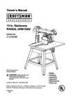
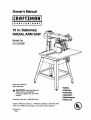
Owner's Manual
I
PR
OFESS
IONAL
I
i
10 in. Stationary
RADIAL ARM SAW
Model No.
315.220381
Save this manual for
future reference.
•
•
•
•
•
•
CAUTION:
Read and follow all
Safety Rules and Operating
Instructions before first use of this
product.
Customer Help Line: 1-800-932-3188
Sears,
Roebuck
Visit the Craftsman
972000-705
10-99
and Co.,
Hoffman
Estates,lL
60179
web page: www.sears.com/craftsman
USA
Safety
Features
Assembly
Operation
Maintenance
Parts List
®
FULL ONE YEAR WARRANTY ON CRAFTSMAN RADIAL ARM SAW
If this CRliFT,_MAN" Radial Arm Saw fails due to a defect in material or workmanship within one year from the
date of purchase, Sears will repair it, free of charge.
Contact a Sears Service Center for repair.
If this product is used for commercial or rental purposes, this warranty applies onlyfor 90 days from the date of
purchase.
This warranty gives you specific legal rights,and you may also have other rights which vary from state to state.
Sears, Roebuck and Co., Dept. 817WA, Hoffman Estates, IL 60179
Your saw has many features for making cutting operations more pleasant and enjoyable. Safety, performance
and dependability have been given top priority in the design of this saw making it easy to maintain and operate.
A
CAUTION: Carefully read through this entire owner's manual before using your new saw. Pay close
attention to the Rules For Safe Operation, and all Safety Alert Symbols, includingDanger, Warning and
Caution. If you use your saw properly and only for what it is intended, you will enjoy years of safe, reliable
service.
_1
Look for this symbol to point out important safety precautions.
involved.
It means attentionl!!
Your safety is
WARNING:
The operation of any power tool can result in foreign objects being thrown into your eyes,
which can result in severe eye damage. Before beginning power tool operation, always wear
safety goggles or safety glasses with side shields and a full face shield when needed. We
recommend Wide Vision Safety Mask for use over eyeglasses or standard safety glasses
with side shields, available at Sears Retail Stores.
• Warranty and Introduction ...............................................................................................................................
2
• Table of Contents ..........................................................................................................................................
2-3
•
Rules For Safe Operation .............................................................................................................................
4-7
• Electrical ........................................................................................................................................................
8-9
• Product Specifications and Glossary ........................................................................................................
• Unpacking and Accessories ..........................................................................................................................
• Loose Parts List ........................................................................................................................................
• Tools Needed .................................................................................................................................................
10-1
11
12-14
15
• Labels........................................................................................................................................................
16-17
• Features ....................................................................................................................................................
18-21
•
22-36
Assembly...................................................................................................................................................
Assembling Leg Stand ...................................................................................................................................
MountingSaw to Leg Stand ...........................................................................................................................
CRRFI"SHAN'
RADIALSAW315.220381
2
22
23
Attaching Elevating Handwheel .....................................................................................................................
Installingthe Yoke Assembly .........................................................................................................................
23
24
Removing the Blade .......................................................................................................................................
AttachingTable Supports ..............................................................................................................................
Setting the Arm Lock Knob ............................................................................................................................
25
25
26
Setting the Yoke Clamp .................................................................................................................................
26
Setting the Bevel Lock Lever .........................................................................................................................
27
Tightening the Arm and Column ....................................................................................................................
28
Adjusting the Column Tube ......................................................................................................................
28-29
Adjustingthe Carriage Bearings ....................................................................................................................
Leveling the Table Supports ..........................................................................................................................
Installingthe Front Table ...............................................................................................................................
30
31
32
Leveling the Front Table ................................................................................................................................
33
Installing Rear Table, Spacer Table, Fence, and Clamps ........................................................................ 33-34
Installing Blade and Blade Guard ..................................................................................................................
Aligning Riving Knife to Blade ........................................................................................................................
34
35
InstallingRip Scale Indicators ............................................ ,...........................................................................
36
• Adjustments ..............................................................................................................................................
36-42
Aligning the Arm for Cross Cuts ......................................................................................... :.......................... 37
•
Aligning the Blade to Table at 0" Bevel .........................................................................................................
Squaring Blade to Fence ...............................................................................................................................
Paralleling Blade to Table ..............................................................................................................................
38
39
40
Aligning the Rip Scale Indicators...................................................................................................................
InstallingControl Cut Device .........................................................................................................................
41
42
Operation ..................................................................................................................................................
Basic Operation of the Radial Arm Saw ........................................................................................................
Types of Cuts .................................................................................................................................................
Switch and Switch Key...................................................................................................................................
Causes of Kickback .......................................................................................................................................
43
43
44
44
Avoiding Kickback..........................................................................................................................................
44
Cutting Aids ....................................................................................................................................................
Making a Cross Cut .......................................................................................................................................
Making a Miter Cut .........................................................................................................................................
45
46
47
Making a Bevel Cut ........................................................................................................................................
Making a Compound Cross Cut .....................................................................................................................
Rip Cut Hazards and Precautions .................................................................................................................
48
49
50
Setting Up a Rip Cut ......................................................................................................................
•
43-53
_.......... 50-51
Making a Rip Cut ...........................................................................................................................................
Making Other Cuts .........................................................................................................................................
Cutting Long Workpieces ...............................................................................................................................
Non-Through Cuts .........................................................................................................................................
51
52
52
53
Maintenance ..................................................................................................................................................
54
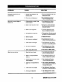
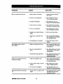
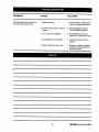
• Troubleshooting ........................................................................................................................................
55-59
•
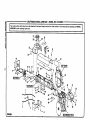
Exploded View and Repair Parts Ust .......................................................................................................
60-81
•
Parts Ordering / Service ....................................................................................................................
3
back page
i:llnlrrsNnr
RADIALSAW315.220381
The purpose of safety symbols Is to attract your attention to possible dangers. The safety symbols, and
the explanations with them, deserve your careful attention and understanding. The safety warnings do
not by themselves eliminate any danger. The instructions or warnings they give are not substitutes for
proper accident prevention measures.
MEANING
SYMBOL
A
SAFETY ALERT SYMBOL
Indicates danger, warning or caution. May be used in conjunctionwith other symbolsor
pictographs,
_,
DANGER: Failure to obey a safety warning will result in sadous injuryto yourself or to others.
Always follow the safety precautionsto reduce the risk of fire, electricshock and personal injury.
WARNING: Failure to obey a safety warning can result in serious injuryto yourself or to others.
Always follow the safety precautions to reduce the risk of fire, electric shock and personal injury.
CAUTION: Failure to obey a safety warningmay result in propertydamage or personal injuryto
yourself or to others. Always follow the safety precautionsto reduce the risk of fire, electric shock
and personal injury.
Note:
Advises you of informationor instructionsvital to the operation or maintenance of the equipment.
IMPORTANT
_k
WARNING: Do not attempt to operate this tool
until you have read thoroughly and understand
completely all instructions,safety rules, etc.
contained in this manual. Failure to comply can
result in accidents involvingfire, electric shock,
or serious personal injury. Save owner's manual
and review frequently for continuing safe
operation, and instructingothers who may use
this tool.
READ ALL INSTRUCTIONS
•
M KNOW YOUR POWER TOOL. Read the owner's
manual carefully. Learn the saw's applicationsand
limitations as well as the specific potential hazards
related to this tool.
MAKE WORKSHOP CHILD-PROOF with padlocks
and master switches or by removing switch keys.
M USE THE RIGHT TOOL FOR THE JOB. Do not
force the tool or attachment to do a job it was not
designed for. Use it only the way it was intended.
Servicing requires extreme care and knowledge of the
system and should be performed only by a qualified
service technician. For service we suggest you contact
your nearest Sears repair center. Always use original
factory replacement parts when servicing.
If you have questions about terms in the following
rules, refer to the Glossary of Terms for Woodworking
or the Features section.
i
B DRESS PROPERLY. Do not wear loose clothing,
gloves, neckties, rings, bracelets, or other jewelry.
They can get caught and draw you into moving
parts. Nonslip footwear is recommended, Also
wear protective hair coveringto contain long hair.
DO NOT USE IN DANGEROUS ENVIRONMENT.
Do not use power tools near gasoline or other
flammable liquids,in damp or wet locations, or
expose them to rain. Keep the work area well lit.
m KEEP CHILDREN AND VISITORS AWAY. All
visitors should wear safety glasses and be kept a
safe distance from work area. Do not let visitors
contact the tool or extension cord while operating.
i
ALWAYS WEAR SAFETY GLASSES WITH SIDE
SHIELDS. Everyday eyeglasses have only impactresistant lenses; they are NOT safety glasses.
M KEEP WORK AREA CLEAN. Cluttered work
areas and work benches invite accidents. DO NOT
leave tools or pieces of wood on the saw while it is
in operation. Keep floors clean and free of sawdust.
i
NEVER STAND ON TOOL. Serious injury could
occur if the tool is tipped or ifthe blade is unintentionallycontacted.
•
DO NOT OVERREACH. Keep proper footingand
balance at all times.
n MAINTAIN TOOLS WITH CARE. Keep tools sharp
and clean for better and safer performance. Follow
instructionsfor lubricating and changing accessories.
i
SECURE WORK. Use clamps or a vise to hold
work when practical. It's safer than using your
hand and frees both hands to operate the tool.
[lUI_NaN'
RADIALSAW316320381
4
•
USE THE PROPER EXTENSION CORD. Make
sure your extension cord is in good condition, Use
only a cord heavy enough to carry the current your
product will draw. An undersized cord will cause a
drop in line voltage resulting in loss of power and
overheating. A wire gage size (A.W.G.) of at least
14 is recommended for an extension cord 25 feet
or less in length. If in doubt, use the next heavier
gage. The smaller the gage number, the heavier
the cord,
•
AVOID ACCIDENTAL STARTING. Be sure switch
is off when plugging in the tool.
•
REMOVE WRENCHES AND ADJUSTING KEYS.
Get in the habit of checking - before turning on the
tool - that hex keys and adjusting wrenches are
removed from tool.
•
•
•
USE ONLY CORRECT BLADES. Use the right
blade style for the material and the type of cut.
Use only blades marked for at least 5,000 rpm and
10 in. or smaller, with a 5/8 in. arbor hole.
KEEP GUARDS IN PLACE and in good working
order. This includes the blade guard, the riving
knife, and the anti-kickback pawls.
CHECK DIRECTION OF FEED. When ripping, •
feed work into a blade or cutter against the direction of rotationof the blade or cutter.
•
NEVER LEAVE TOOL RUNNING UNA'I'rENDED.
TURN THE POWER OFF. Do not leave the tool
until it comes to a complete stop.
•
•
DO NOT FORCE THE TOOL. It will do the job
better and moresafely at the rate for which it was
designed.
•
BEFORE MOUNTING, DISCONNECTING OR
REMOUNTING THE MOTOR; unplug the saw and
remove the switch key.
_l,
CHECK DAMAGED PARTS. Before using the tool
again, check any damaged parts, including guards,
for proper operation and performance. Check
alignment of moving parts, bindingof moving parts,
breakage of parts, saw stability, mounting,and any
other conditionsthat may affect its operation. A
damaged part must be properly repaired or replaced by a qualified service technician at a Sears
repair center to avoid risk of personal injury.
•
•
DISCONNECT ALL TOOLS. When not in use,
before servicing, or when changing attachments,
blades, bits, cutters, etc., all tools should be
disconnected from the power supply.
WARNING: When servicing, use only identical
Craftsman replacement pads. Use of any other
parts may create a hazard or damage product.
•
NEVER USE THIS TOOL IN AN EXPLOSIVE
ATMOSPHERE. Normal sparking of the motor
could ignite fumes.
•
MAKE SURE THE WORK AREA HAS AMPLE
LIGHTING to see the work and that no obstructions will interfere with safe operation BEFORE
performing any work using this tool.
•
DO NOT USE TOOL IF SWITCH DOES NOT
TURN IT ON AND OFF. Have defective switches
replaced by a qualified service technician at a
Sears repair center.
•
GUARD AGAINST ELECTRICAL SHOCK by
preventing body contact with grounded surfaces
such as pipes, radiators, ranges, refrigerator
enclosures.
•
GROUND ALL TOOLS. See Electrical page.
• WEAR A DUST MASK to keep from inhaling fine
particles. Use wood dust collection systems
whenever possible.
•
PROTECT YOUR HEARING. Wear hearing
protectionduring extended periods of operation.
•
DO NOT OPERATE THIS TOOL WHILE UNDER
THE INFLUENCE OF DRUGS, ALCOHOL, OR
ANY MEDICATION.
USE RECOMMENDED ACCESSORIES. Using
improper accessories may risk injury. Consult the
Accessories section for recommended acceSsories.
STAY ALERT AND EXERCISE CONTROL. Watch
what you are doing and use common sense. Do
not operate tool when you are tired. Do not
rush.
USE ONLY SEARS REPLACEMENT PARTS. All
repairs, whether electrical or mechanical, should
be made by a qualified service technician at a
Sears repair center.
•
5
AVOID AWKWARD OPERATIONS AND HAND
POSITIONS where a sudden slip could cause your
hand to move into the blade, ALWAYS make sure
you have good balance•
qlIIFt3NlUr
RADIALSAW$15.220_t
•
•
•
GUARD AGAINST KICKBACK. Kickbackcan
occur when the blade stalls, driving the work piece
back toward the operator. It can cause your hand
to contact the blade, resulting in serious personal
injury. Stay out of the blade path and turn switch
off immediately if blade binds or stalls.
•
ALWAYS PUSH THE WORKPIECE when ripping;
never pull it toward the saw.
DO NOT FEED THE MATERIAL TOO QUICKLY.
Do not force the workpiece against the blade.
DO NOT USE A PERSON AS A SUBSTITUTE
FOR A TABLE if additional support is needed. Use
a support the same height as the table.
• ALWAYS TURN OFF SAW before disconnecting
it, to avoid accidental startingwhen reconnecting
to the power supply. NEVER leave the saw
unattended while connected to a power source.
USE A SUPPORT FOR THE SIDES AND BACK
OF THE SAW TABLE when sawing wide or long
workpieces to minimize the risk of blade pinching
and kickback. Use a sturdy "outrigger"support to
prevent tipping if a table extension more than 24
inches long is attached to the saw.
•
CUT ONLY WOOD, PLASTIC OR WOOD-LIKE
MATERIALS. Do not cut metal.
•
BEFORE MAKING A CUT, be sure all adjustments
are secure.
•
NEVER cut more than one piece at a time. DO
NOT STACK more than one workpiece on the saw
table at a time.
•
DO NOT REMOVE THE SAW'S BLADE GUARD.
Never operate the saw with the blade guard
removed. Make sure all guards are operating
properly before each use.
•
NEVER PERFORM ANY OPERATION FREEHAND. Always place the workpiece to be cut on
the saw table and position it firmly against the
fence as a backstop.
•
USE THE RIP FENCE. Always use a fence or
straight edge guide when ripping.
•
BE SURE THE BLADE PATH IS FREE OF
NAILS. Inspect for and remove all nails from
lumber before cutting.
•
BE SURE THE BLADE CLEARS THE WORKPIECE. Never start the saw with the blade touching
the stock.
•
KEEP HANDS AWAY FROM CUTTING AREA.
Do not reach underneath work or in blade cutting
path with your hands and fingers for any reason.
Always turn the power off when cut is complete.
•
USE A PUSHBLOCK OR PUSHSTICK in rip mode
for workpieces so small that your fingers go under
the blade guard. NEVER TOUCH BLADE or other
moving parts during use, for any reason.
ALLOW THE MOTOR TO COME UP TO FULL
SPEED before starting a cut to avoid blade binding
or stalling.
•
BEFORE CHANGING THE SETUP, REMOVING
COVERS, GUARDS, OR BLADE; unplugthe saw
and remove the switch key.
•
KEEP TOOL DRY, CLEAN, AND FREE FROM
OIL AND GREASE. Always use a clean cloth
when cleaning. Never use brake fluids, gasoline,
petroleum-based products, or any solventsto
clean tool.
KEEP BLADES CLEAN, SHARP AND WITH
SUFFICIENT SET. Sharp blades minimize stalling
and kickback. Keep blades free of rust, grease,
and pitch.
_k
•
WARNING:
off.
Blade coasts after being
" turned
=
USE ONLY OUTDOOR EXTENSION CORDS.
Use only extension cords with the marking =Acceptable for use with outdoor appliances;store
indoorswhile not in use." Use extension cordswith
an electrical rating not less than the saw's rating.
Always disconnectthe extension cord from the
outlet before disconnectingthe productfrom the
extension cord.
INSPECT TOOL CORDS AND EXTENSION
CORDS PERIODICALLY and, if damaged, have
repaired by a qualified service technician at a
Sears repair center. Stay constantlyaware of cord
locationand keep it well away from the moving
blade.
•
DO NOT ABUSE CORD. Never yank the cord to
disconnectit from receptacle. Keep the cord from
heat, oil, and sharp edges.
•
SAVE THESE INSTRUCTIONS. Refer to them
frequently and use to instructother users. If you
loan someone this tool, loan them these instructions also.
SAVE THESE INSTRUCTIONS
Clltl_HIIIr
RADIALSAW315.220381
6
•
SECURE THE SAW. Firmly belt the saw to the leg
stand to keep the saw from tipping,walking, or
sliding.
•
DO NOT SET UP WORK WITH THE BLADE
SPINNING. Keep the saw power off until you are
ready to use it.
•
•
•
KEEP THE SAW BLADE PATH CLEAR. Position
the saw to allow enough room on all sides so
neither the operator nor a visitor stands in line with
the sawblade.
RIP ONLY WORKPIECES LONGER THAN THE
BLADE'S DIAMETER. Never rip a piece of wood
that is shorter than the diameter of the blade.
•
NEVER LOWER AN UNLOCKED REVOLVING
CUTTING TOOL. Always lock the carriage lock
knob before lowering the blade.
AVOID HEELING by adjusting the saw blade so it
exactly parallels the fence during rippingoperations.
•
AVOID GRABBING in rip mode by keeping the
saw blade correctly adjusted and by feeding the
work from the infeed side (opposite the antikickback pawls).
•
AVOID PINCHING by using a rivingknife and
sharp saw blade. Keep the work positionedfirmly
against the fence.
•
USE IN-RIP WHENEVER POSSIBLE by positioning the work so the blade is between (inside) the
column and the motor.
• SHUT OFF THE POWER TO FREE A JAMMED
GUARD. Press the switch off before puttingyour
hands near the blade. Wait for the blade to stop,
then free the guard.
•
LOCK THE SAW BEFORE MOVING IT. Secure
the radial arm with the arm lock knob. Secure the
carriage with the carriage lock knob.
• POSITION THE WORKPIECE WITH THE FINISHED SIDE DOWN. If the anti-kickback pawls
catch the wood to stop kickback, they could mar
the top surface or cause splintering.
•
POSlI_ION THE WORKPIECE SO NO ONE MUST
STAND IN LINE WITH THE BLADE. if kickback or
climb occurs, a helper, operator, or observer in the
sawblade path could be seriously injured.
•
POSITION THE CUT SO THE WASTE PART
FALLS OFF. Never use a length stop on the free
end of the workpiece. Never apply force to the free
end or hold it while the sawblade is rotating.
_i,
•
BEFORE CUTTING, position and tighten the blade
guard and anti-kickback pawls. Test the pawls to
make sure they would stop kickback if it started.
Keep the points sharp.
'NEVER ADJUST GUARD, PAWLS, OR BLADE
WITHOUT DISCONNECTING THE POWER.
Always turn off the switch and unplug the cord
before freeing a jammed blade, tighteninga loose
blade, or repositioningthe guard or pawls.
_k
NEVER CUT MORE THAN ONE PIECE OF
WOOD AT A TIME. The feed will be uneven and
could cause the blade to pick up one or more
pieces and cause serious injury.
WARNING: In a ripcut, holding the cut-off edge
behind the blade can cause the cut edges to
pinch, riskingkickback, tt could cause the blade
to climb over the front edge of the wood and
contact your hand.
TURN OFF SAW IF A STRANGE NOISE OR
HEAVY VIBRATION OCCURS. Immediately turn
off the saw, locate the source, and correct the
problem before using the saw further.
POSITION THE CUT SO THE BLADE WILL NOT
EXTEND BEYOND THE EDGE OF THE TABLE.
BEFORE STARTING EACH CUT, check that no
play exists in the carriage. Be sure the arm, yoke
and bevel locks and clamps are tight. Verify the
blade, all handles, blade washers, and blade nuts
are secure.
•
BEFORE MAKING A CUT, test the upper and
lower blade guards for free movement up and
down. Positionthe nose of the guard to just clear
the workpiece.
•
AVOID KICKBACK AND POSSIBLE INJURY by
preventing heeling, grabbing, and pinching.
CAUTION: Do not turn the motor switch on and
off rapidly. This can loosen the sawblade.
KEEP THE GUARDS IN PLACE AND THE WORK
SURFACE CLEAR DURING A CUT. Small objects
or wood slivers can ricochet from the blade into the
fence and back toward the operator. If the blade
loosens slivers, remove them with a stick, not your
hand.
IN A RIP CUT, DO NOT LET GO OF THE WORKPIECE UNTIL THE CUT IS COMPLETE. When the
workpiece is fed intothe blade, push the workplace
all the way past the blade.
7
CRIIFI"SNIIN'RADIALSAW315.220381
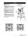
EXTENSION
CORDS
GROUNDINGINSTRUCTIONS
Use only 3-wire extension cords that have 3-prong
grounding plugs and 3-pole receptacles that accept
the tool's plug. When using a power tool at a considerable distance from the power source, use an extension cord heavy enough to carry the current that the
tool will draw. An undersized extension cord will
cause a drop in line voltage, resulting in a loss of
power and causing the motor to overheat. Use the
chart provided below to determine the minimum wire
size required in an extension cord. Only round jacketed cords listed by Underwriter's Laboratories (UL)
should be used.
Length of Extension Cord
In the event of a malfunction or breakdown, grounding
providesa path of least resistance for electriccurrent
to reduce the risk of electric shock. This tool is
equipped with an electric cord having an equipmentgroundingconductor and a grounding plug. The plug
must be plugged into a matching outlet that is prepedy
installedand grounded in accordance with all local
codes and ordinances.
Do not modify the plug provided. If it will not fit the
outlet, have the proper outlet installed by a qualified
electrician. Improper connection of the equipmentgroundingconductor can result in a risk of electric
shock. The conductor with insulationhaving an outer
surface that is green with or without yellow stripes is
the equipment-groundingconductor. If repair or
replacement of the electric cord or plug is necessary,
do not connect the equipment-groundingconductorto
a live terminal.
Wire Size (A.W.G.)
Up to 25 feet
26-100 feet
14
12
When working with the tool outdoors, use an extension cord that is designed for outside use. This is
indicated by the letters WA on the cord's jacket.
Check with a qualified electrician or service personnel
if the grounding instructionsare not completely
understood, or if in doubt as to whether the tool is
propedy grounded.
Before using an extension cord, inspect it for loose or
exposed wires and cut or worn insulation.
_k
CAUTION: Keep the cord away from the cutting
area and position the cord so that it will not be
caught on lumber, tools, or other objects during
cutting operations.
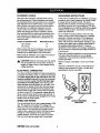
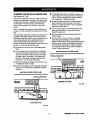
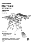
ELECTRICAL
Repair or replace a damaged or worn cord immediately.
This tool is intended for use on a circuit that has an
outlet like the one shown in Figure 1. It also has a
grounding pin like the one shown.
CONNECTION
Your Sears Craftsman Radial Arm Saw is powered by
a precision built electric motor. It should be connected
to a power supply that is 120 volta, 60 Hz, AC only
(normal household current). It should be connected
to a 240 volt power supply only if it has been reset
according to the Instructions in this manual. The
motor has been set at the factory for 120 volts; if it is
reconnected to operate at 240 volts, the main power
cord plug and any receptacle must be replaced with
devices rated for 240 volts. This tool will not operate
on direct current (DC). A substantial voltage drop will
cause a loss of power and the motor will overheat. If
the saw does not operate when plugged into an outlet,
double check the power supply.
GROUNDING
PIN
COVEROFGROUNDED
OUTLETBOX
SPEED AND WIRING
The no-load speed of your saw is approximately 3,600
rpm. This speed is not constant. For voltage, the
wiring in a shop is as importantas the motor's horsepower rating. A line intended only for lights cannot
properly carry a power tool motor. Wire that is heavy
enough for a short distance will be too light for a
greater distance. A line that can support one power
tool may not be able to supporttwo or three tools.
rRIIFTSNIIrRADIALSAW316.220381
8
Fig. 1
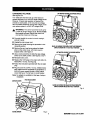
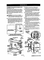
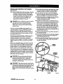
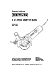
CHANGING
VOLTAGE
See Figures 2-4.
LIFTMOTORCOVERTO EXPOSESWITCH
Your radial saw has been set up at the factory to
operate efficiently on a 120V AC single voltage circuit.
However, if heavy duty operation is required, the
circuits are overloaded, or the circuit is low voltage,
have a qualified electrician change the voltage on the
main power system to a 240V AC voltage circuit.
,_
WARNING: The control cut device is set up for
a 120V AC single voltage circuit. Do not modify
the control cut cord. Identify the controlcut
cord and tie it back out of the way.
•
Correctly identify the control cut cord, unplug it,
and set it aside.
•
Unplug the main power cord.
•
Remove the blade followingthe procedure in the
Assembly section.
•
Remove the pan head screw above the blade
arbor on the motor cover. Lift motor cover to
expose switch. See Figure 2.
•
Use a small screwdriver to slide the dual voltage
switch to the 240V position. See Figures 3 and 4.
Reinstall motor cover.
•
SLIDEASSHOWNFORSINGLEVOLTAGECIRCUITS
SWITCHSHOWNIN 110-120VOLTPOSmON
Fig. 3
UFT MOTORCOVERTO EXPOSESWITCH
•
Replace the 120V plug on the main cord with a UL
listed 240V, 15 amp, 3-prong plug.
•
Follow the instructionsprovided with the UL listed
plug.
•
Plug the cord into a 240V, 15 amp, 3-blade receptacle. Make sure the receptacle is connected to a
240V AC power supply through a 240V branch
circuit that has a 15 amp fuse or circuit breaker.
Note: No adapter is available for this type of plug or
receptacle.
MOTORCOVER
PANHEADSCREW
SLIDEAS SHOWNFORDUALVOLTAGE
CIRCUITS
SWITCHSHOWNIN 220-240VOLTPosmoN
Fig. 4
O
BLADEARBOR
Fig. 2
9
(RIIR'SHnN"RADIAL
SAW315.220381
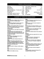
BladeArbor
BladeDiameter
BladeBevelAngle
Radial Arm Swing Range
518in.
10in.
0°- 90 °
Cutting Capacity - Maximum In-Rip
2.25 in.
Table Size
5.35 in.
40 x 27.75 x 1 in.
36 in.
Table Height
Carriage Travel
17.25 in.
Rating
Cutting Capacity - Maximum Cross Cut
15.50 in.
Input
Cutting Capacity - Maximum Out-Rip
3in.
Depth of Cut at 45"
45" minimum left - 90" right
Blade Height Adjust
16 in.
Depth of Cut at 90"
26 in.
No Load Speed
120V/240V
60 Hz -AC only
13.0/6.5 Amperes
3,600 RPM
Bevel Cut
Infeed
A cut made across a workpiece with the blade at any
angle other than 90" to the table surface.
Chamfer
The side of the blade where the blade teeth point up,
opposite the anti-kickback pawls.
In-Rip
A type of rip cut in which the blade is between the
column and the motor.
A cut removing a wedge from a block so the end (or
part of it) is angled rather than at 90 degrees.
Climb
A hazard in which the blade "climbs" over and out of
the workpiece, pulling the stock out of the operator's
hands or running across the workpiece.
Kerr
The space left by the removal of material in a cut or
the slot produced by the blade in a non-throughcut.
Kickback
A hazard that can occur when blade binds or stalls,
throwing workpiece back toward operator.
Compound Cut
A cross cut with both a miter angle and a bevel angle.
Cross Cut
A cutting operation with the blade parallel to the
carriage arm and the blade teeth pointingdown. It can
be across or with the grain, normally across the grain
or width of the workpiece.
Dado Cut
A non-throughcut that leaves a square notch or
trough; requires a special blade.
Leading End
The end of the workpiece pushed into the cutting tool
first.
Miter Cut
A vertical cut made at any angle other than 0" across
the workpiece.
Molding
A shapingcut that gives a varied shape to the
workpiece and requires a special blade.
Featherboard
A device to help guide workpieces during ripcuts•
Fence
A piece of wood used as a edge guide for the
workpiece. Located perpendicular to the carriage arm.
Can be placed at different distances from the rear
table edge in combination with the other table pieces
and is secured with table clamps•
Freehand
Out-Rip
A type of rip cut in which the motor is between the
blade and the column• (The blade is "outside" the
motor).
Puahatick
A device used to feed the workpiece through the saw
blade duringcutting operations. It helps keep the
operator's hands well away from the blade.
Dangerous practice of making a cut without using a
fence.
Gum
Rabbet
A type of cut that gives a notch in the edge of a
workpiece.
A sticky, sap-based residue from wood products.
Heel
Alignment of the blade to the fence.
Resaw
A cutting operation to reduce the thickness of the
workpiece to make thinner pieces,
[IIRR3MIIIr RADIAL
SAW31S_220381
10
Resin
A sticky, sap-based substance.
Throw-Back
Saw throwing back a workpiece similar to kickback.
Rip Cut
In a radial saw, a cut made with the blade parallel to
the fence and perpendicular to the arm. Can be
across or with the grain. The teeth point up at the
point of contact with the wood.
Through Sawing
Any cutting operation where the blade extends
completely through the workpiece.
Trailing End
The workpiece end last cut by the blade in a rip cut.
Sawblade Path
The area directly in line with the blade -- over, under,
behind, or in front of it. Also, the workpiece area which
will be or has been cut by the blade.
Set
Workpiece
The item on which the cutting operation is being done.
The surfaces of a workpiece are commonly referred to
as faces, ends, and edges.
Worktable
The surface on which the workpiece rests while
performinga cutting operation.
The distance that the tip of the saw blade tooth is off
set from the face of the blade.
_i,
_lb
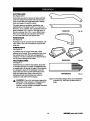
• Carefully remove all parts from the carton and
place the saw on a level work surface. Separate
and check against the list of loose parts.
WARNING: To prevent accidental starting that
could cause possible serious personal injury,
assemble all parts to your saw before connecting
it to power supply. The saw should never be
connected to the power supply when you are
assembling parts, making adjustments, installing
or removing blades, or when not in use.
•
Do not discard the packing materials until you have
carefully inspected the saw, identified all parts, and
satisfactorilyoperated your new saw.
Note: If any parts are damaged or missing, do not
attempt to plug in the power cord and turn the
switch on until the damaged or missing parts
are obtained and are installed correctly.
WARNING: If any parts are missing, do not
operate this tool until the missing parts are
replaced. Failure to do so could result in possible
serious personal injury.
The following recommended accessories are currently available at Sears Retail Stores.
•
•
•
Steel and carbide tipped circular saw blades
Hold down clamps
Saw baskets
_lb WARNING:
•
•
Adjustable taper jig
Sawdust collector shroud
The use of attachments or accessories not listed might be hazardous.
11
[RAFTSNAN' RADIALSAW315,220381
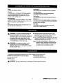
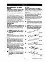
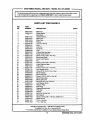
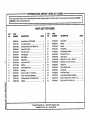
Check all loose parts from the box with the list below. Use the instructionson the followingpages to assemble.
All fasteners are shown actual size.
1.
Saw Assembly ....................................................
1
SAWASSEMBLYSHOWNASPACKED
Fig. 5
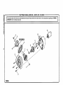
2.
Elevating Handwheel .
A. Handwheel .......... :.......... _.......... :.................... 1
3.
Blade Wrench ..................................................... 2
4.
Hex Key
B. Screw (10-24 x 5/8 in. Soc. Hd.) .................... 1
C. Star Washer ...................................................
1
A. 3/16 in. Hex Key ............................................. 1
B. 1/4 in. Hex Key............................................... 1
C
Fig. 6A
[lUlFTSMIIM' RADIALSAW315.220381
12
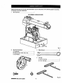
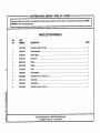
Checkall
loose parts from the box with the list below. Use the instructionson the followingpages to assemble.
All fasteners are shown actual size.
5.
9.
Saw Base To Leg Stand Assembly
Fence ..................................................................
1
A. Saw Assembly (not shown) ........................... 1
B. Leg Stand Assembly (not shown) .................. 1
C. Hex bolt (5/16-18 x 518 in. Hex Head) ........... 4
D. Washer (5/16 in.) ........................................... 8
E. Lock washer (5/16 in.) ................................... 4
F. Hex Nut (6/16-18) ........................................... 4
10. Leveling Hardware for Front Table
A. Screw (1/4-20 x 1-3/4 in.) .............................. 1
B. Washer ........................................................... 1
C
6.
D
E
F
Hardware for Front Table
C, U-clip ..............................................................
D. Setscrew ........................................................
1
t
E. Tee nut ...........................................................
1
A. Front table .................................................... ,. 1
B, Screw (1/4-20 x 1 in.) ..................................... 4
C. Washer (1/4 in.) ............................................. 4
D. Lock washer (1/4 in.) ..................................... 4
A
B
E. Hex nut (1/4-20) ............................................. 4
D
E
11. Scale Indicator
B
7.
C
D
A. Screw .............................................................
4
B. Speed Nut ......................................................
C. Indicator .........................................................
2
2
D. Switch Key .....................................................
2
E
Rear Table ........................................................... 1
C
IIoII
8.
Spacer Table ......................................................
1
Fig. 6B
13
CHR2NH" RADIALSAW316,220381
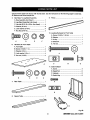
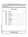
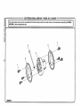
Check all loose parts from the box with the list below. Use the instructions on the following pages to assemble.
All fasteners are shown actual size.
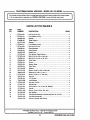
15. Leg Stand ...........................................................
1
A. Table Support Rails ....................................... 2
A. Leg .................................................................
4
B. Square,head bolt (5/16-18 x 3/4 in.) .............. 4
C. Flat washer (5/16 in.) ..................................... 4
B. Long bottom brace ......................................... 2
C, Long top brace ............................................... 2
D. Lock washer (5/16 in.) ................................... 4
D. Short bottom brace ........................................ 2
E. Hex nut (5/16-18) .................... ....................... 4
E. Short top brace .............................................. 2
12. Table Support
F. Foot ................................................................
4
G. Screw (1/4-20 x 5/8 in.) ............................... 40
H. Star washer .................................................. 40
A
I. Hex nut (1/4-20) ............................................ 40
J. Hex nut (3/8-16) .............................................. 8
14. Owner's Manual (not shown) ............................. 1
G
F
m
000
H
I
J
Fig. 6C
CRIIFT,_NAIr
RADIALSAW315.220381
14
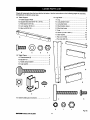
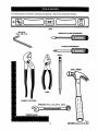
The following tools are needed for assembly and alignment. They are not includedwith this saw.
io@C
LEVEL
HEXKEYS:
5/32in.ANDI/8 in.
MEDIUMFLATBLADESCREWDRIVER
#2 PHILLIPSSCREWDRIVER
PENCIL
SMALLHAMMER
PLIERS
WRENC S 7/161n,1/21n,9/161n_15/161n
FRAMINGSQUARE
t5
Fig. 7
rEAFTSMRIr
RADIAL
SAW315.220381
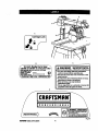
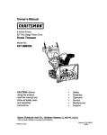
A
A
c
(I
10 inch Radii
i
Arm Saw
A WARNING/ ADVERTENCIA
I 3,_RPM 120/?._ImVOLT_
1316.SAJnp60Hz ACONLYI
I WHEN
_RVlCING,
USEOl'€.y
I_NTICALC_
|
I RE_.A_NTPARTS.
_
r
I MOOEL 315.22_181
SER,NO
ill
• For your own safety, Read and understand
owner's manual before operating saw.
* This tool has more than one connection to the
power soorce.
. To reduce the risk of electrical shock or injury,
disconnect al| power connections
• When servicing, use only identical
replacement parts.
• Par,, su seguddad, lea y entlenda el manual del
propieterio antes de oparer la sierra,
/_1_ i I
D
,I
lilll
I_
Fig. 8A
£HfTg411r RAI_L SAW$IS_20_
16
On I
OffO
G
./"
F_
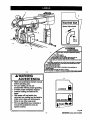
A WARNING
;_,,_,..
ADVERTENCIA
_[yo, r a.duty,
readowners
remrelbelore
qereUng
jv
jr
• Wear sofely goggles.
_r • DOnotperformfreehandcuts.
jr • Returncarriageto full roar positionafter each crosscut.
jr • See thutnmtisnsonhowto reducetheriskofkickback,
jr • Whenripping,use pushsUchwhenblade is set 2 Inchesor morefrom
/
then.
j_ • Whenripping,use puchbthckandauxiliaryfencewhenbladeis osl between
1/2 and2 Inchesfromfelwe. Denutreakedp cutsosrmwar thsa1/2tnch.
• Keep handsOutof pathof blade.
• no notreacharoundsaw blade.
• Turnpower Oftandwaif forblade to stepbeforereevingwarkplose or
changing|eRinos.
• Unplugsaw beforechangingthe blade or servicing,
• Parssuseguridad,lea y entlendeel manualdel preplutarlo
antesde opersrla sierra
G
_WARNING
ADVERTENCIA
H
• Read and understand owners manual
before operating saw.
• For your safety, do not use
accessories without proper guarding.
• Provide proper workpiece support
• Position cutting tool behind the
fence.
• With power off and switch key
removed, turn cutting tool by hand to
make sure it does not strike guard,
fence or any other saw parts.
• Pars su saguridad, lea y entienda el
manual del propietario antes de
operar la sierra.
LOCKED
UNLOCKED
,
Fig, 8B
17
rltllFI3NIIlr RADIAL
SAW315.220381
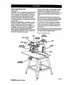
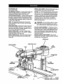
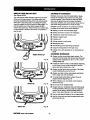
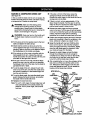
KNOWYOURRADIALSAW
Control functions include 1) column height (elevating
handwheel), 2) arm angle (arm lock knob), 3) yoke
movement on arm (*carriage lock knob) 4) yoke
rotation(*yoke pivot latch and *yoke lock handle), and
5) blade bevel (*bevel index lever and *bevel lock
knob).
See Figure 9A.
OVERVIEW - The main operating components include
the column, the arm, and the yoke assembly (yoke,
motor, and blade), and their operation is summarized
in the paragraph below. Safety features and control
functionsare given also. Spending a few minutes
reviewing the illustrationsand features list below and
on the following pages to locate these items will make
assembly easier.
Safety features includethe control cut device, the
removable switch key, and the blade guard assembly.
Never operate the saw without ensuring these safety
features are in place and functioning correctly.
METHOD OF OPERATION: The column at the back
of the saw supports the radial arm. The arm can be
raised or lowered to change the blade height or
swiveled left and right for a miter cut. A yoke fits into
a carriage on the arm, which can travel back and
forward. The yoke supportsthe yoke assembly
(motor, blade, and blade guard) and can be pivoted
so the blade faces right, front, or left. The motor can
be rotated to change the blade angle.
On a radial saw, "cross cut" means a cut parallel to
the arm, and a "rip cut" is perpendicularto the arm.
There are several ways to make cuts, depending on
the size and material of the workpiece and the end
resultdesired.
Before attempting to use your saw, familiarize yourself
with all operating features and safety requirements of
your Sears Craftsman Radial Arm Saw.
*Shown on following pages
CONTROL
CUTHOUSING
YOKE
ARMLOCKKNOB
CARRIAGE
ANDCOVER
SWITCHANDKEY
BLADEAND
BLADEGUARD
COLUMN
MOTOR
ELEVA_NG
HANDWHEEL
Fig. gA
cRnFt3MIIrRADIALSAW315.220381
18
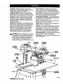
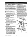
FEATURESLIST
BEVEL LOCK LEVER - Sets and locks blade angle. It
is located below the handle. See Figure 9B.
BLADE - For maximum performance, use the Craftsman 40-tooth, 10 in. carbide-tipped blade provided
with your saw. It is a high-qualitycombination blade
suitable for rippingand crosscut operations. Blades
recommended for other operations are listed in the
Accessory section of this manual. The blade is
powered by the main motor and turned off by the
switch. See Figure 9D.
See Figures 9A-9D.
ADJUSTABLE TABLES - A_narrow spacer table and
wider rear table that can be repositioned or even
replaced with different tables. See Figure 9C.
ANTI-KICKBACK PAWLS - Toothed pawls that snag
the work in case of kickback during rip cuts. (When
the blade is parallel to the arm, the pawls are in front
of the blade.) Keep the pawls in place to reduce risk
of injury. See Figure 9D.
ARM - The assembly extending from the column,
which supports the yoke, the motor, and the blade.
See Figure 9A.
,_
ARM LOCK KNOB - Controls arm angle. Use to set
the arm to the positive stops at 0°, 45" left, and 45"
right and to lock the arm in place. Located on top of
arm at front. See Figures 9A and 9B.
WARNING: Use only blades rated for at least
5,000 rpm and recommended for use on this
saw. Check with your nearest Sears retail store.
BLADE GUARD ASSEMBLY - Protective unit over
the blade, with a riving knife, anti-kickback pawls, an
upper blade guard, a lower outer blade guard, and a
lower inner blade guard. Always keep each item in
place unless specificallyinstructedto move it. See
Figures 9A and 9D.
BLADE GUARD CLAMP SCREW - Secures the
blade guard to the motor. Located between the blade
andthe motor. See Figure 9D.
BEVEL INDEX KNOB - Controls the blade angle
between positive stops at 0 °, 45", and 90 °. Located
behind the handle. See Figure 9B.
BEVEL INDEX SCALE - Shows the blade angle for
bevel cuts and is located behind the handle. See
Figure 9B.
MITERSCALE
YOKEPIVOTLATCH
ARMLOCKKNOB
RIP
SCALE(S)
YOKE
COLUMNTUBE
BEVEL
INDEXKNOB
YOKE
LOCKHANDLE
INDEXSCALE
COLUMNSUPPORT
ER
MOTOR
19
Fig. gB
(IIRFTSMRN"
RADIAL
SAW315.220381
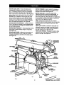
CARRIAGE
- Slidesalongtrackunderarmand
supports
yoke.Contained
intwocarriage
covers,one
oneachsideofthearm.See Figure 9C.
DUAL VOLTAGE - If needed, your main power
source may be rewired by a qualified electricianto
providea 240V AC circuit. See the Electrical section.
DUST GUIDE - Directs sawdust, created from the cut
being made, in the directionyou set. Located at the
rear of the upper blade guard. See Figure 9D.
ELEVATING HANDWI-IEEL - The handwbeel below
the worktable (in front) that changes the height of the
arm and the blade. See Figure 9C.
CARRIAGE LOCK KNOB - Controls whether the
cardage is locked or can travel. Located on the left
side of the arm on the carriage cover. See Figure 9C.
COLUMN - Upright housing at the beck of the saw,
consisting of a column support and a column tube.
The column tube can be raised or lowered with the
elevating handwheel at the front of the saw. See
Figures 9A and 9B.
FENCE - Removable guide for work, which extends
across width of table. See Figure 9C.
CONTROL CUT DEVICE - Limitscarriage speed to
prevent climb, using a cable from the carriage to the
column. Has a separate motor on left side, which is
activated by the switch trigger in the handle. The
cable returns the carriage to the column when the
motor is not activated. Speed is adjusted with a
thumbwheel on the handle. It runs on a separate
120V AC single voltage circuit. See Figure 9C.
_1,
FRONT TABLE - Fixed portion of the worktable that
supportsthe work. See Figure 9C.
HANDLE - Used to pull the yoke assembly. Mounted
on the yoke to the right of the blade. See Figure 9C.
HOLD DOWN - A metal guard to control workpiece
climb during rip cuts. When blade parallels arm, hold
down is over the back of the blade. See Figure 9D.
HOLD DOWN KNOB - Controls placement of the hold
down and locks it in place. See Figure 9D.
WARNING: When connecting only one of the
cords, squeeze the switchtrigger in the handle. If
the main motor cord alone is connected, the
switchtrigger in the handle will not operate the
controlout device. The carriage cannot be
advanced without power to the control cut device.
TRACK
MITER SCALE - Shows the miter angle setting of the
arm. See Figure 9B.
CARR_GE
LOCKKNOB
CARRIAGE
ANDCOVER
CONTROL
CUTMOTOR
SWITCH
ANDKEY
CUTCABLE
CONTROLCUT
THUMBWHEEL
REAR
TABLE
FRONTTABLE
SPACER
TABLE
ELEVATING
HANDWHEEL
Fig. 9C
[RFT|NnlrRADIALSAW315.220381
20
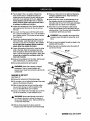
MOTOR
(13/6.5AMP)- Powersthebladeand is
controlled by the switch and key at the front of the
arm. The powerful induction motor has a capacitor
start. It is mounted in the yoke and rotated with the
bevel index knob and bevel lock lever. See Figure 9B.
RIP SCALES - Show the distance from the fence to
the blade. (in-rip scales are on the right side of the
arm, and out-rip scales are on the left side,) Upper
scales show the distance with the fence beside the
front table. Lower scales show the distance with the
fence in farthest back position. See Figure 9B.
RIVING KNIFE OR SPREADER - Located directly in
front of the blade and beside the anti-kickback pawls,
the riving knife keeps cut edges from binding during
rip cuts. See Figure 9D.
RIVING KNIFE BRACKET - Allows adjustment of the
riving knife. Located midway along the rivingknife.
See Figure 90.
SWITCH TRIGGER - Used to power the controlcut
device to allow yoke assembly to be pulled forward.
Mounted inthe handle. See Figure 9D.
SWITCH WITH KEY - Powers the blade motor.
Placed on the front of the arm for easy access. To
lock the switch once it has been pressed to OFF,
remove the yellow key. Place the key in a locationthat
is inaccessibleto children and others not qualified to
use the tool. See Figures 9A and 9C.
YOKE - Supportsthe blade and motor. Can be
pivoted to indexthe blade between rip and cross cuts.
Located between the carriage and the motor. See
Figure 9B.
YOKE PIVOT LATCH - Indexes the yoke (after it is
released) to position the blade to face right (out-rip
cut), front (cross cut), or left (in-np cut). Located on
the right carriage cover. See Figure 9B.
YOKE LOCK HANDLE - Releases the yoke to allow
indexing for rip cut or cross cut. Located below the
yoke, on the right. See Figure 9B.
RIVING KNIFE KNOB - Adjusts the rivingknife and
locks both the pawls and the rivingknife in place.
Located toward the top and front of the blade guard.
See Figure 9D.
BLADEGUARD
CLAMPSCREW
DUSTGUIDE
HOLDDOWN
SWITCH
HOLD
DOWNKNOB
RIVING
KNIFEKNOB
RIVINGKNIFE
BLADEGUARD
RIVING
KNIFEBRACKET
o
BLADEGUARD
ANTI-KICKBACK
PAWLS
o
BLADE
_Fig.
21
9D
[IIRFI]KNIIW
RADIALSAW315,220381
Assembly is best done in the area where the saw will
be used. When you remove the saw and hardware
from the packing materials, carefully check the items
with the Loose Parts list. If you are unsure about the
descriptionof any part, refer to their illustrations.For
your convenience, all fasteners have been drawn
actual size. If any parts are missing, delay assembling
until you have obtained the missing part(s).
Your radial arm saw is capable of a wide variety of
operations, and thus requires a number of initialsetup
adjustments. However, once the saw is set up, you
can check your saw in about ten minutes and correct
any misalignment with the procedures in the Adjustment section.
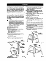
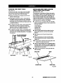
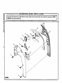
•
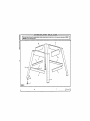
Place a 3/8-16 hex nut on each leveling foot and
insert leveling feet intothe bottom of the legs. Cap
with remaining 3/8-16 hex nuts but only finger
tighten. See Figure I OA.
•
Place a short upper brace inside two of the legs
(wide end of legs up) and align the three holes in
the brace with the holes in the legs.
•
Insert the screws. Add the star washers and 1/4-20
hex nuts. Finger tighten.
•
Install a short lower brace on the legs.
See Figure I OA.
•
Repeat for the other end assembly.
•
Connect the leg sets with a long upper brace. Add
the hardware and finger tighten. Repeat for the
other side brace, then installthe long lower braces.
See Figure lOB.
_1= CAUTION: Perform all the procedures in both
the Assembly and Adjustments sectionsbefore
using the saw. Run a check on your saw
frequently, referring to the Adjustmentssection.
Failure to perform the adjustments in the initial
set up or on a frequent basis can result in boor
performance or machine damage.
• Tighten all screws, washers, and nuts with a 7/16
in. wrench and as needed a #2 phillipsscrewdriver.
•
Move the leg stand to the desired location. Using a
level, adjustthe leveling feet by raising or lowering
the boltswith a 9/16 in. wrench.
ASSEMBLING
LEG STAND
See Figures 10,4- 10C.
•
When the leg stand is level, securely tighten all four
nuts with the wrench.
•
Take the followinghardware from the hardware
bags in the leg stand carton:
40 truss head screws (1/4-20 x 5/8 in.)
40 star washers (1/4 in.)
40 hex nuts (1/4-20)
•
Your leg stand is now completely assembled and
ready for use. See Figure 10C.
•
Take the followinghardware from the remaining
hardware bags in the leg stand carton:
LONG
UPPERBRACE
4 leveling feet
8 large hex nuts (3/8-16)
•
Obtain four legs and eight braces from the leg
stand carton. See the Loose Pans section.
SHORT
SHORT
LOWERBRACE
LONG
LOWERBRACE
Fig. lOB
WASHER
HEADSCREW
HEXNUT
(1/4-20)
HEXNUT
(3/8.16)
LEVEUNGFOOT
[|BmNI_RA_ALSAW315.220_I
Fig. lOA
Fig. 10C
22
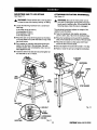
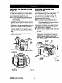
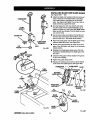
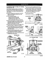
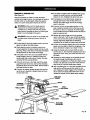
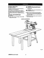
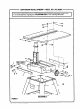
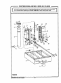
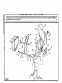
MOUNTING
SAW
See Figure 11.
,_
•
TO LEG STAND
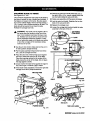
ATTACHING
See Figure 12.
WARNING: Firmly boltthe saw to the leg stand
to keep the saw from tipping, walking, or sliding.
Locate the followinghardware from a small hardware bag:
4
4
8
4
HANDWHEEL
WARNING: Be sure the main power cord of
your saw is unplugged. Ignoring this precaution
could result in serious injury. Do not perform the
followingsteps unless the saw is unplugged.
The elevating handwheel adjuststhe height of the
radial arm and the blade.
hex bolts (5/16-18 x 5/8 in.)
Iockwashers (5/16 in.)
flat washers (11/32 in.)
hex nuts (5/16-18)
• Take the handwheel, star washer, and screw
(10-24 x 5/8 in. Soc. Hd.) from the hardware bag.
•
Place the saw on top of the leg stand so the holes
in the saw base line up with the holes on top of the
leg stand braces.
•
Put a washer on a screw, and put the screw and
washer into the hole in the saw base. Cap with
another washer, then a Iockwasher and a hex nut.
Hand tighten the set.
•
_,
ELEVATING
•
Place the handwheel on the end of the elevating
shaft, which extends from the front of the saw base.
•
Place the star washer on the screw and thread
screw into the end of the shaft.
•
Securely tighten the screw with a 5132 in. hex key.
•
Raise or lower the arm by turning the handwheel.
Install the other three sets and securely tighten all
four sets with a 1/2 in. wrench.
ELEVATING
SHAFT
HANDWHEEL
SCREW
SAW
BASE
LEG
STARWASHER
SAWBASE
i
Fig. 12
HEXBOLT
|
_
_J_,,FLAT
_1
'_,_,*'/I
WASHER
_
LEGs_HEXNUTFig.
/"
LOCKWASHER
11
23
[IIQF1]JNIIN"RADIALSAW315.220381
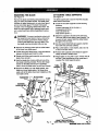
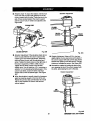
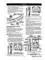
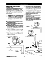
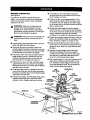
INSTALLING
THE
YOKE
• FORCLARITY,CARRIAGE
COVERSANDCARRIAGELOCK
KNOBARENOTSHOWNIN ILLUSTRATION
ASSEMBLY
See Figures 13A - 13C.
The yoke rides in the carriage below the arm and
supports the motor, the blade guard, and the blade.
Install the yoke assembly from the front of the arm.
•
ARMLOCKKNOB
BEARINGS(4)
Remove the carriage stop screw and Iockwasher
from below the front of the arm with a 1/4 in. hex
key. See Figure 13A.
CARRIAGE
ARMVIEWEDFROMBELOW
YOKE
='_"____._LcOC
q::==::::===_l,_
•
KWASH
ER
,
sc.°w
Fig. 13A
Remove the arm cap screws and arm cap from the
front of the arm with a phillipsscrewdriver. See
Figure 13B.
CARRIAGE
LOCKKNOB
ARM
ARMLOCKKNOB
ARM
CAPSCREWS
CARRIAGECOVER
Fig. 13C
Fig. 13B
•
•
Remove and discard the two motorsetscrews in
the bottom of the motor. They are for shipping
purposes only.
Reinstallthe cardage stop screw, the Iockwasher,
arm cap, and arm cap screws. Tighten all screws
securely.
•
Using the elevating handwheel, raise the arm 3
inches and remove the packing material.
•
Lock the arm with the arm lock knob, located on top
of the front of the arm, so the arm doesn't swing
while you are mounting the yoke assembly.
_1, WARNING: Once the yoke assembly is on the
carriage track, reinstallthe arm cap, the arm cap
screws, the cardage stop screw, and the
Iockwasher. Do not dsk sedous injury or damage
to the saw by failing to replace these parts.
•
Pick up the yoke assembly and carefully slip it onto
the carriage track below the arm. Keep it parallel
with the arm so bearings slide in smoothly. See
Figure 13C.
• Tighten the carriage lock knob, on the carriage
cover on the left of the arm, to lock the yoke
assembly in place.
CIUIFt3MlUf RADIALSAW315.220381
24
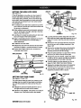
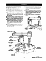
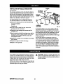
REMOVING
THE
See Figure 14.
ATTACHING
See Figure 15.
BLADE
Remove the blade and blade guard assembly during
setup for safety and better access. The blade guard
includes an upper blade guard, an outer lower guard,
and an inner lower guard. The lower inner guard
consists of two overlapping slotted metal strips. The
strips are held together with a retaining screw and a
nut. Locate these items before beginning the procedure.
_,
WARNING: To prevent accidental contact with
the blade that could result in injury, remove the
blade and blade guard before making setups
involvingthe blade arbor and work stand. Use
the blade wrenches provided with your saw.
TABLE
SUPPORTS
The table supports are a base for the three wooden
table sections and fence.
•
Locate the two table supportsand the following
hardware:
4 square head bolts (5/16o18 x 3/4 in.)
4 Iockwashers(5/16 in.)
4 hex nuts (5/16-18)
4 flat washers (5/16 in.)
•
Attach the supportsto the side of the saw base.
There are holes in both sides of each support.The
long side of each support (with the slotted holes)
fits against the saw base.
•
Use two square head bolts per support, inserted
from within the saw base outward.
•
Remove the retaining screw and nut at the bottom
of the lower inner blade guard.
•
Place a flat washer, a lock washer, and a hex nut
on the end of each screw.
•
Loosen the guard clamp screw, a long thumbscrew
between the blade guard and the motor.
•
Positiontable supportsso that bolts are approximately (;entered in slotted holes.
•
Rotate and lift the guard assembly up and over the
blade, then remove it,
•
•
Hold the blade arbor (motor shaft) with one of the
two blade wrenches provided. Put the other blade
wrench on the blade nut and turn it clockwise
(down), since the blade arbor has left hand threads.
Finger tighten or snug with a 112in. wrench only at
this time. Final adjustments will be made later in
Leveling The Table Supports section.
•
Remove the blade nut, outer blade washer, saw
blade, and inner blade washer, Set these items
aside until all the tables have been installed and the
front table is level.
THUMBSCREW
BLADEGUARD
TABLE
SUPPORT
FLAT
WASHER
SQUARE
HEADBOLT
BLADE
RETAINING
SCREWANDNUT
TO
LOOSEN
\
BLADE
ROTATION
INNERBLADE
WASHER
TABLE
SUPPORT
TO
BLADE
WRENCH(2)
BLADE
ARBOR
Fig, 14
MOUNTTABLESUPPORTS
USINGTHESEHOLELOCATIONS
Fig. 15
25
rRBFTSMIIB
°RADIAL
SAW315.220381
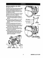
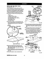
SETTING THE ARM LOCK KNOB
ARMCAP
MOTOR
See Figure 16.
It may be possible to move the arm when locked, if
the arm lock knob is too loose. If the arm does not
move freely when unlocked, the arm lock knob may
be too tight. Use this procedure to check and set the
arm lock knob by turning the arm lock wheel (under
the carriage arm).
•
To release the arm lock knob, located on top of the
arm at the front, pull the arm lock knob forward until
the spring is compressed.
•
While holdingthe arm lock knob forward, swing the
arm 30" to the left or the right, referring to the miter
scale on top of the column.
•
YOKELOCK
HANDLE
YOKE
ASSEMBLY
Lock the arm in place by pushing the arm lock knob
back until it pops in the locked position.
•
•
Apply a reasonable amount of pressure on the arm.
The arm can be forced but if it moves easily, it
needs adjustment.
• Locate the arm lock wheel.
•
Release the arm lock knob and turn the lock wheel
clockwise to tighten or counterclockwiseto loosen.
•
Repeat above steps until the arm movement is
minimized when locked.
ARM LOCKKNOB
TURNCOUNTERCLOC_
WISETOLOOSEN
TURNCLOCKWISE
TO TIGHTEN
ARM
LOCKWHEEL
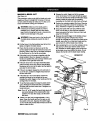
SETTING
THE
•
ARM
CARRIAGE
STOPSCREW
•
YOKE
Fig. 16
Fig. 17A
Lock the yoke lock handle. Grasp the motorwith
both hands and apply reasonable pressure to see if
it slips. If it moves, reset the yoke lock handle as
follows.
Remove the arm cap screws and arm cap at the
front of the arm with a phillipsscrewdriver. See
Figure 13B.
Remove the carriage stop screw and Iockwasher
with a 1/4 in. hex key. Carefully slide the yoke
assembly forward and off the carriage.
•
Place the yoke assembly in a spot where it will be
secure as you work on the top of the yoke.
•
Release the yoke lock handle. Tighten the center
nut with a 15/16 in. wrench until the lock handle is
centered between the two legs of the yoke.
•
Carefully replace the yoke assembly on the carriage arm track. Slide it back about halfway.
•
Replace the carriage stop screw and Iockwasher,
followed by the arm cap and arm cap Screws.
•
Lock and test the yoke again. If it can be moved,
repeat the procedure until it is secure.
_lil
_J_ m_
CENTERNUT
CLAMP
See Figures 17,4and 17B.
YOKELOCK
HANDLE
The yoke clamp keeps the yoke from rotating on the
carriage when you want the saw blade to be stationary. Use this procedure to check and set the yoke
clamp.
•
Release the yoke lock handle (below the arm on
the right side) so the motor can be rotated.
•
Swivel the motor slightly. It shouldbe at an angle in
between one of the preset positive stop angles.
LEG
Fig. 17B
tlIAFI_MRIr RADIAL
SAW315.220381
26
SETTING
THE BEVEL
See Figures 18A -18C.
LOCK
LEVER
The bevel lock lever locks the blade at desired angles
other than the preset positive stop angles. The bevel
lock lever is preset at the factory but may need
readjustment after shippingor extended use. Check
for overUghtnessor looseness and make any necessary adjustments as follows:
The bevel lock lever is located on the front of the yoke
assembly, near the bottom. It is attached to a clamp
bolt that controlsthe amount of tightness.
•
Pull the bevel lock lever forward to unlock it. Use
the bevel index knob (just under the handle) to
rotate the motor approximately 30 °. Lock the bevel
lock lever.
•
If the bevel lock lever is difficultto lock, the clamp
bolt needs to be loosened. If the motorcan be
forced out of position, the clamp belt needs to be
tightened.
•
STARWASHER
BEVEL
LOCKLEVER
Remove the socket screw (under the bevel lock
lever) and star washer with a 1/8 in. hex key.
•
Use the bevel lock handle as a wrench to tighten or
loosen the clamp belt. The clamp bolt has a righthanded thread. Tighten it left to right.
•
When the bolt is correctly set, remove the bevel
lock lever from the clamp bolt and place it roughly
parallel to the yoke assembly.
•
Replace the socket screw and star washer. Recheck the tightness of the bevel lock lever. Repeat
the steps above until the motor is secure when
locked, and the bevel lock lever fits squarely
against the yoke assembly.
1/8 In.HEXKEY------_
Fig. 18B
BEVELLOCKLEVERIN
CORRECTLOCKEDPosmoN
Fig. 18C
BEVEL
LOCKLEVER
BEVEL
INDEXKNOB MOTOR
Fig. 18A
27
[RIIFTSMIIIr RADIALSAW31S.22_1
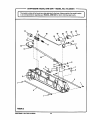
TIGHTENING
THE
ARM AND
COLUMN
ADJUSTING
THE
COLUMN
TUBE
See Figure 19.
See Figures 20A - 20D.
There should be no play, vertical or horizontal, in the
arm relative to the column. If you can move the arm
up, down or sideways when )he arm lock is unlocked,
use the followingsteps to tighten the arm.
The purpose of this procedure is to check whether the
inner column tube is snug in the housing and to
remove any looseness. Looseness could resultin a
poor cut or difficultyin elevating the carriage. The
column tube is the upper portion of the column and
extends from the column support.
Note: The arm should pivot only when the arm lock
knob is unlocked and pulled forward to compress the spring.
•
Using a phillipsscrewdriver, remove the rear cover
screws (2) and rear cover from the back of the arm.
This uncovers the belts on the column.
•
Tighten the top two belts evenly until the arm is firm
and there is no verticalor horizontal movement.
•
Also check the two bettom hex nuts. It is not
necessary to tighten them as tight as the upper
bolts. However they should be tightened even and
snug.
•
Replace the rear cover and rear cover screws.
•
Tighten screws securely.
Note: It is criticalto remove all looseness with this
procedure. If this procedure is not done correctly,following adjustments will be wrong and
could result in machine damage.
This procedure checks beth the elevating actionand
the rotating action. If a check does not show looseness, do not perform the adjustment.
REAR
COVERSCREWS
•
If the arm is not at O"(straight forward), release the
arm lock knob, set the arm, and re-lock the arm
lock knob.
•
Elevation check:To check the elevation movement,
place your hand under the frontof the radial arm.
Press upward on the radial arm. There shouldbe
minimal play between the column tube and the
column support.The whole assembly shouldmove
as one. See Figure 20A.
COLUMN
TUBE
REAR
COVER
ARM
HEXBOLT(2)
COLUMN
SUPPORT
Fig. 20A
HEXNUT(2)
€IulFrsNlU(' RADIALSAW315.220_1
Fig. 19
28
•
Elevation Adjustment
Rotationcheck:To check the rotation, hold the front
of the arm with one hand and grasp the top of the
column supportwith the other. Press the arm to the
side. If there is play between the column support
and the column tube, it needs to be adjusted. See
Figure 20B.
COLUMNTUBE
COLUMN
COLUMN
SILVER
COLUMNSUPPORT
Fig. 20B
Fig. 20C
Elevation Adjustment: If the elevation check did not
show any play between the column tube and the
support, go to the rotationadjustment. Otherwise,
raise and lower the arm with the elevating handwheel. Tighten the black screws on the right side of
the column supportby 1/16th to 1/8th of a turn.
Tighten the two silver screws on the left side
slightlymore. You will need two 1/2 in. wrenches or
sockets. Turn the elevating handwheel again. If the
column tube binds, loosen the silverand black
screws and turn the handwheel again. See Figure
20C.
•
BLACK
SCREWS
•
RotationAdjustment:Usinga3/16in. hex key,
slightlytighten the two cap screws at the back of
the column support (left side) untilno play shows
between the radial arm and the column.The cap
screws are indicated by arrows. See Figure 20D.
•
Recheck the rotationby holdingthe front of the
arm, grasping the top of the column supportwith
the other, and pressingthe arm to the side,
Rotation Adjustment
When the elevation is smooth, check for looseness
again by pressing upward on the front of the arm.
Repeat the previous step until elevation is smooth
with no play between the column tube and the
column support.
CAP
SCREWS
Fig. 20D
29
aRIRSMIU£RADIAL
SAW315.220381
ADJUSTING THE CARRIAGE BEARINGS
•
Use a 9/16 in. wrench to hold the eccentric screw
(top of bearing) and a 1/2 in. wrench to loosen the
nut below the bearing.
•
Turn the eccentricscrew a partial turn as needed to
tighten the bearing.
•
Retightenthe nut and repeat the second step to
test the tightness. Adjust it so the bearing turns
even against resistance when the carriage is
moved - but not so much that the carriage is difficult
to move and return it to its rear position.
•
Repeat for the left rear bearing.
See Figures 21A and 21B.
Loose carriage bearings permit the blade to wander
slightly while cutting, which will result in a poor cut
and more wear and tear on the saw. Use the following
steps to check for tightness and to then adjust the
bearings if needed.
•
On the left side of the arm, remove the carriage
lock knob, the carriage cover screws, and the
carriage cover.
•
With one hand, grip the front bearing hard to keep it
still, and pull the carriage forward with the other
hand. The bearing shouldturn. If it stays stillas the
carriage is moved, it needs to be adjusted.
Note: Adjust bearings on the left side only. Bearings
on the right side do not adjust.
•
CARRIAGEBEARING
Replace the carriage cover, carriage cover screws,
and cardage lock knob.
ECCENTRICSCREW
GRASPANDHOLD
CARRIAGEBEARING
Fig. 21A
9/16in.
WRENCH
WRENCH
Fig. 21B
C|Al_Nlnr
RADIALSAW315.220381
30
LEVELING
THE TABLE
See Figures 22A and 22B.
SUPPORTS
Place the wrench below the shaft and check that
the clearance is the same. If not, adjust the table
supportuntil it is the same. Securely tighten the
front screw.
The table supportsmust be perfectly level.
• Pull the bevel lock lever forward to unlockit. Use
the bevel index knobto rotate the motor so the
arbor shaft points down. Lock the bevel lock lever.
•
Release the arm lock knob to angle the arm. Begin
by positioningthe arbor shaft over the back of the
highest table support. Normally this is the left side.
See Figure 22A.
•
Lock the arm lock knob and the carriage lock knob.
•
Using one of the blade wrenches as a feeler gage,
place it on the table support below the arbor shaft.
•
With the elevating handwheel, carefully lower the
motor until the shaftjust touches the wrench. The
wrench should move with only slight resistance.
Securely tighten the back screw on the table
support.
•
Without changing the elevation, move the arm to
place the blade arbor over the front of table support. See Figure 22B.
Move the arm to the opposite side and repeat the
above procedure. When the opposite side is level,
recheck the first side to make sure that it is still
accurate and even.
•
Return the saw and motor to normal height and
position.
BLADE
WRENCHAT
FRONT
Fig. 22B
ARMLOCKKNOB
BEVEL
INDEX KNOB
BEVEL
LOCK LEVER
BLADE WRENCH
AT BACK
BLADE
ARBOR
RIGHTSIDE
TABLESUPPORT
LEFT SIDE
TABLE SUPPORT
ELEVATING
HANDWHEEL
Fig. 22A
31
[RRF1_NRrRADIALSAW315.220381
INSTALLING THE FRONT TABLE
U-CLIP
AUGNU-CUP
See Figures 23A - 23C.
Use this procedure to install the fixed front table.
OVERTHISHOLE
The top of the table has counterbored holes, predrilled
from the top, around the center to attach the table. In
the center are a counterbored hole and a small hole,
which is not counterbored. They are used for raising
or lowering the center of the table until it is level.
•
•
Locate the front table and the followinghardware:
1 tee nut
1 U-clip (1/4 in.)
1 setscrew (1/4-20 x 7/8 in.)
4 pan head screws (1/4-20 x 1 in.)
1 pan head screw (1/4-20 x 1-3/4 in.)
5 flat washers (5/8 in.)
4 lock washers (1/4 in.)
4 hex nuts (1/4-20)
SAWBASE
Place the front table on a solid worksurface,with
the top surface face down. Race the tee nut in the
non-counterboredhole and tap it in place with a
hammer.
Fig. 23B
•
SETSCREW
_
SCREW
f_l
r
_'_._,_
I
ol
___
23A.
FLAT
_
Place the long pan head screw into the center hole
and thread into the U-clip. Do not tighten until the
table has been checked for evenness. See Figure
•
WASHER
Place the setscrew through the small leveling hole
and thread intothe tee nut, but do not tighten.
_k
•
REAROF
ing holes and through the holes in the support.
Cap with a lock washer and hex nut. Tighten with a
7/16
wrench
and head
phillipsscrewdriver.
This
Put ain.
1 in.
long pan
screw in the four
remaincompletes installationof the front table.
1-3/4 in. SCREW /|
SCREW L
]
!'I /
_' T'
REAROFFRONTTABLE
ELAT
'
WASHER
i
Fig. 23A
•
Snap the U-clip onto the front edge of the saw
base. Line up the hole in the U-clip with the saw
base hole just to the left of the center notch in saw
base. See Figure 23B.
•
Place the table, top up, on the table supportsso the
center counterbored hole lines up over the hole in
the U-clip.
•
Place a flat washer in each counterborsd hole.
HEXNUT
LOCKWASHER
Fig. 23C
[|lll_NlUr
RADIALSAW315.220381
32
LEVELING
THE
See Figure 24.
FRONT
TABLE
INSTALLING
REAR TABLE, SPACER
TABLE, FENCE, AND CLAMPS
See Figures 25A - 25C_
If there are any high or low areas on the front table,
they should be removed by adjusting the leveling
screws in the center holes on the front table.
•
The placement of the tables and fence may need to
be changed for different cuts, depending on the size
of the workpiece and the positionof the blade. The
fence should be installed next to the front table for
maximum depth capacity; it should be installed in the
middle for maximum cross cut capacity; and installed
all the way back for maximum rip capacity.
Place the rear table on its edge across the front
table to check for gaps.
• Adjust gaps of less than 1/32 in. in the center of
the table by turning the setscrew with a flat blade
screwdriver until the setscrew touches the frame.
Then lightly secure the center pan head screw with
a phillipsscrewdriver.
•
B Locate the fence, the spacer table, the rear table,
and two unassembledclamps, which consistof the
following hardware:
For a gap of more than 1/32 in. in the center of the
table, raise the center by turning the setscrew
against the frame. Then lightlysecure the center
pen head screw with a phillipsscrewdriver.
2
2
2
2
B For a gap of more than 1/32 in. on the sides, lower
the center of the table by tighteningthe center pan
head screw with a phillipsscrewdriver. Then tighten
the setscrew.
PHILLIPSSCREWDRIVER
ONPANHEADSCREW
cup washers
clamp brackets
square nuts
thumbscrews
•
Place the fence behind the front table, then the
spacer table behind it, and then the rear table
behind it,
•
Slip a square nut intothe slot of each clamp
bracket.
B Place a thumbscrew intothe end of the clamp
bracket farthest from the slot. Thread it intothe
square nut.
SETSCREW
Note: If the screw is inserted in the wrong end of the
bracket, the clamp will not work.
•
Place the clamp bracket into the rectangle holes in
the table support. Hold the cup washer againstthe
rear table and turn the thumbscrewclockwiseuntil
it snaps into the cup washer.
• Tighten the thumbscrews to clamp the table sections intoplace.
REARTABLE
REARTABLE
FENCE
FRONTTABLE
Fig. 24
SPACERTABLE
FRONTTABLE
Fig. 25A
33
rRIIR'SMmN"RADIALSAW$1S,220,_1
INSTALLING
BLADE
See Figures 26,4 •
THUMBSCREW
•
CLAMP
BRACKET
AND
BLADE
GUARD
26C.
Collect the blade and hardware that were removed
earlier. Place the inner blade washer, saw blade,
outer blade washer, and blade nut on the blade
arbor. See Figure 26,4. Note: The concave side of
blade washers go against the blade.
Hold the blade arbor with one wrench and rotate
the other blade wrench counterclockwise (up), to
tighten the blade nut. See Figure 26B. Note: Blade
arbor has left hand threads. Test the blade to make
sure it turns freely.
SQUARENUT
CLAMPSHOWN
i
CUP
WASHER-------.-_
ASSEMBLED
SLOT
•
Use the bevel index knob (above the handle) and
the bevel lock lever (below the handle) to set and
lock the motor at 0". The blade will be vertical.
•
Attach the blade guard over the blade so the riving
knife and pawls face front. See Figure 26,4.
•
Tilt the guard approximately 45" down in the front,
place it over the blade, and rotate it to a horizontal
locked position.
•
Retighten the blade guard clamp screw, the long
thumbscrew located between the blade guard and
the motor.
•
Check that the guard is firmly seated in the groove
on the motor housing.
•
Tighten the guard clamp screw.
•
Replace the retaining screw and nut at the bottom
of the lower inner blade guard. See Figure 26C.
Fig. 25B
HOLE
THUMBSCREW
BLADEGUARD BLADE
TABLE
SUPPORT
RETAINING
BCREWAND NUT
CUP
TO
LOOSEN
RIVING KNIFE
AND PAWLS
TO
TIGHTEN
BLADE NUT
INNERBLADE
WASHER
TO
Fig. 26A
SCREW
BLADE
ROTATION
TO
;HTEN
BLADE
WRENCH(2)
BLADE
Fig. 25C
Fig. 26B
[RAR3MIIIrRADIALSAW315.220381
34
Orient inner slotted metal stdp so that it is located
to the left of outer slotted metal strip.
To prevent binding, align flats of retaining screw nut
in slots of inner slottedmetal strip.
Insert retaining screw through outer slotted metal
stdp and thread into retaining screw nut. Tighten
retaining screw securely.
FLATS
RETAINING INNERSLOTTED
METALSTRIP
RIVINGKNIFEONTOPOFFENCE
TOOFARLEFTOFBLADE
X
W NUT
OUTER SLOTTED
METAL STRIP
Fig. 27B
\
between the motor and the column. Lock the yoke
lock handle.
With the elevating handwheel, lower the arm until
the blade just clears the table.
LOWERINNER
_BLADE
RETAINING
SCREW"--ALIGN RIVING
KNIFE
See Figures 27A - 27C.
GUARD
Supportthe lower outer blade guard and loosen the
carriage lock knob on the left of the arm. Move the
yoke back until the blade touches the fence. Reset
the carriage lock knob.
( IIJ/
_
Fig. 26C
TO BLADE
Loosen the rivingknife knob, at the front of the
upper blade guard. Lowerthe rivingknife to the
table and tighten the knob. If the knife rests against
the fence, with one set of pawls dding on the fence,
no adjustment is needed.
When rippingthe rivingknife must be centered with
the blade to ride in the middle of the kerf and keep it
from binding. Bindingpinches the blade. Blade
pinchingcan cause kickback.
If the rivingknife is on the fence or not touching it,
loosen the dving knife slotted nut (just above the
pawls, to the right). Correct the dving knife position
and retightenthe cap nut.
There are two pairs of anti-kickback pawls.
_1 WARNING: Failure to use the dying knife, hold
downs, and anti-kickback pawls can allow
kickback. Kickback can throw the workpiece
toward the operator, resulting in serious injury.
CARRIAGE
Put the blade to the in-dp position by first loosening
the yoke lock handle, below the cardage on the
dght. Then pull the yoke pivot latch (right side of
arm, on carriage) forward and rotate the yoke to the
left. This indexesthe yoke 90 ° so the blade is
YOKE LOCK
:HANDLE
RIVING
RIVING
KNIFE
FRONT
TABLE
FENCE
RIGHT OF FENCE AND BLADE
CORRECTALIGNMENTOFTHERIVINGKNIFE
ANDANTI-KICKPAWLS
Fig. 27C
Fig. 27A
35
CRAFTSMAN"
RADIAL SAW 315.220381
INSTALLING
RIP SCALE
SCREWS
INDICATORS
See Figure 28,
RIP SCALE
INDICATOR
The rip scale indicators on the arm show the distance
between the blade and the rip fence with the fence in
the front and rear positions.The upper scale is used
when the fence is positioneddirectly behind the front
table. The lower scale is used when the fence is at the
extreme rear, directly in front of the column,
SPEEDNUT
CARRIAGE
The In-Rip Indicator is on the right side of the arm.
The Out-Rip Indicator is on the left side of the arm,
•
•
Remove the followingfrom a small hardware bag.
SPRING
2 rip scale indicators
4 screws
2 speed nuts
On the left of theradial arm saw, remove the
carriage lock knob and spring.
•
Remove the two carriage cover screws and the
carriage cover.
•
Insert a speed nut inside the carriage cover with the
flat side up. Place the scale indicatoron top of the
carriage cover and attach with two screws. Securely tighten screws.
•
Replace the carriage cover and tighten the carriage
cover screws.
•
Replace carriage lock knob and spring.
•
Repeat for the right side.
CARRIAGE
LOCKKNOB
Fig. 28
To complete setting up your saw, continue with the
Adjustment procedures.The adjustments should be
checked regularly, depending on usage. Your saw will
provide accurate cuts with fine tolerances as long as
you protectthe accuracy with frequent alignment
checks. The radial arm saw can perform a wide range
of high quality cuts.
The final step will be connecting the control cut
device. The control cut device offers many benefits.
As it increases operator control, it eliminates the risk
in a cross cut of the saw "climbing" out and over the
workpiece at the operator. Feed control of the blade
as it cuts through the workplace increases, as does
the accuracy of the cut. The following adjustments
need to be completed before the control cut device is
connected.
Your radial arm saw is designed to perform a variety of
complex cuts with fine tolerances. A weekly alignment
check ensuresthat your saw can performwith precision.
It takes about ten minutes and the results is batter
performance and a longer life for your saw.
_,
Perform the checks in the order given. If you miss an
adjustment, go back to the missed adjustment and
repeat all steps from that point forward.
r'RARYMAN'
RADIALSAWS15,320381
SCREWS
36
CAUTION:
Failure to check alignments and
perform the adjustments in the initialset up or on
a frequent basis can result in poor performanceor
machine damage.
ALIGNING
THE ARM
See Figures 29,4 - 2gC,
FOR CROSS
CUTS
Release the arm lock knob. Positionthe arm
straight forward (0") and leave it unlocked.
Lowerthearm withtheelevating
handwheeluntil
the saw blade just clears the fronttable. Lock the
yoke lock handle (right side of saw, below yoke)
and the bevel lock Lever.
This procedure checks whether the arm is exscfiy O"
for cross cut travel by checking the blade against the
table and the miter indicator. Remove the rear table,
spacer table, and fence, but leave the front ta_e in
place. You will need a framing square, a 3/16 in. hex
key, and a pencil,
_k
•
•
Place the framing square on the table and position
one edge of the square firmly against the back
edge of the table, Positionthe other leg of the
square against the blade until it rests beside but not
touching a tooth. With a pencil, mark beside this
tooth.
•
Slowlymove the yoke assembly forward and
backward along the arm and against the square
without rotatingthe blade. If the mark moves into or
away from the square, adjust the arm with the
followingsteps.
At the back of the column, loosen the three setscrews w_tha 3/16 in. hex key and positionthe arm
as needed to align with the framing square.
WARNING: Be sure the saw is unplugged
before performingthese adjustments. Accidental
start-up could result in serious personal injury.
First check the framing square by fitting one side
against the back edge of the table. Lightlydraw a
line on the table along the edge of the square in
the middle of the table. Flip the square over. If the
edge still matches the line with no gaps or overtape, the square is true.
•
•
Lock the arm lock knob and retightenthe three
setscrews. Recheck the cross cut travel with the
blade against the framing square.
•
Set the miter indicator on top of the column to O"
•
Replace the fence, spacer table, rear table, and
table clamps.
REARCOVER
REMOVEDFOR
CLARITY
THERESHOULDBENOGAPHEREWHEN
SQUAREIS FUPPEDOVERTODOTrEDPOSITION
Fig. 29A
MITERINDICATOR
ARM
LOCKKNOB
Y_E
LOCK
H_O_
FRAMING
SQUARE
\
SETSCREWS
Fig. 29C
ELEVAnNG
HANDWHEEL
Fig. 29B
37
CRIIFTZNIIr
RADIAL
SAW315.220381
ALIGNING BLADE TO TABLE AT 0 ° BEVEL
•
If there are no gaps, fully tighten each screw. If
then is stilla gap, repeat the previoustwo steps.
•
Check the bevel indicator on the yoke assembly
near the handle. It should read 0% If it does not,
reset it by looseningthe screws and rotatingthe
bevel index cap. Retighten the two screws.
•
Loosen the carriage lock knob.
See Figures 30A - 30D.
This procedure squares the blade to the table at O"
bevel (vertical) so the blade angle will be accurate. If
the blade is r_otat O"bevel, follow the steps below to
rotate slightly. You will need a framing square and a
1/4 in. hex key.
• Positionthe blade in front of the fence. Lower the
blade with the elevating handwheel until it just
clears the fronttable.
•
BLADESQUARETO TABLE
NOADJUSTMENT
NEEDED
Lock the followingcontrols:
bevel lock lever below the handle,
carriage lock knob on the left side,
arm lock knob on top of the arm, and
yoke lock handle below the yoke, on the right.
•
Stand a framing square on the table with the short
leg pointingup against the saw blade and the long
leg parallel to the fence. Place the square flat
against the blade between two teeth.
•
If boththe top and bottom of the saw blade aN flat
against the square, no adjustment is needed.
•
If the saw blade gaps at the top or bottom, remove
the bevel index cap by removing the two phillips
head screws (below the handle). You will see four
socket head screws.
•
Loosen the socket head screws with a 1/4 in. hex
key. Rotate the motor slightlywhile holdingthe
square against the saw blade and table top.
•
Slightlytighten each of the four screws and recheck
the blade and framing square.
FRAMING
SQUARE
TABLE/
Fig. 3OB
FRAMING
SQUARE
GAP
BLADE
BLADE
ARMLOCKKNOB
GAP-ADJUSTMENTNEEDED
Fig. 3OC
INDEXCAP
m
BEVEL
LOCK
LEVER
FRONTTABLE
ELEVATING
HANDWHEEL
41
41
¸
SOCKET
HEADSCREWS
Fig. 3OA
BEVELINDEX
CAPREMOVED
_
BEVEL
LOCKLEVER
Fig. 30D
ClIIIFTSMJlr
RADIALSAW315.220381
38
SQUARING
BLADE
See Figures 31A - 31C.
TO FENCE
This procedure squares the miter angle of the blade to
the fence to reduce the risk of bindingand kickback. If
the blade is not square to the fence, the yoke assembly must be rotated slightly. Have a framing square, a
1/2 in. wrench, and a phillips screwdriverat hand. The
blade should be lowered to just clear the table.
Release the carriage lock knob.
,_
•
Release the yoke lock handle (below the yoke on
the right). With a 1/2 in. wrench, slightlyloosen the
two hex bolts holdingthe yoke pivot latch.
•
Rotate yoke assembly untilthe gap is eliminated.
•
Lock the yoke lock handle. Retightenthe two hex
boltson the yoke pivotlatch.
•
Replace the carriage cover.
•
Loosen the carriage lock knob and guide the yoke
assembly to the back of the arm.
WARNING: The blade must be angled at 90" to
the fence when the handle is at the frontof the
saw. If not, kickback could result during a cross
cut. Kickback can cause serious injuryby throwing the workpiece toward the operator. In addition, a faulty miter angle on the blade can splinter
or burn the cut edges of the workpiece during
cross cuts or rip cuts.
•
Use the arm lock knob to index and lock the arm in
O"miter position (straight forward).
•
Pull the yoke assembly forward to the front of the
arm. Lock the carriage lock knob.
•
Place the short end of the framing square against
the fence. Rotate the square to 45" to the table.
Place the long edge across the flat surface of the
blade, below the center of the blade. (Do not place
the edge against a tooth.)
•
Check whether the blade is flat against the edge for
the entire length or whether a gap is visible.
•
If the blade needs adjustment, remove the right side
carriage cover with a phillipsscrewdriver.
FS'oW%W ,
BLADE
RAMINGSQUARE
NOADJUSTMENT
NEEDED
ARMLOCKKNOB
FRAMING
SQUARE
BLADE
FENCE
GAPADJUSTMENTNEEDED
Fig, 31B
FENCE
HEXBOLTS
FRAMINGSQUARE
YOKELOCKHANDLE
Fig. 31C
Fig. 31A
39
(RlU:t3NIIIr RADIALSAW315.220381
PARALLELING
BLADE
See Figures 32A-32C.
TO TABLE
•
This procedure squares the blade to the table at 90"
bevel so horizontal cuts will be accurate. This also
reduces kickback, as well as splintering and burning
of the cut edges of the workpiece. If the blade is not at
90" bevel, follow the steps to rotate the blade unit
slightly. You will need a framing square and a flat
blade screwdriver.
_k
•
•
Check whether the blade is fiat against the edge
the entire length or whether a gap is visible. If you
can see a gap, adjustthe blade to be at 90" bevel
to the table with the followingsteps.
Unlock the bevel lock lever. Loosen the rear motor
mount nut, which holds the motor on the yoke,
Place a flat blade scrawddver in one of the slots,
and rotate the cam behind the nut to eliminate the
gap between the blade and the square.
•
Retighten the nut.
• Tighten the bevel lock lever. Recheck the blade
and the square for any gaps.
WARNING: The blade must be perfectly parallel
to the table at the 90" reading on the bevel scale,
If not, kickback could result, as well as splintering or burningthe cut. Kickback can result in
serious personal injuryas the workpiece can be
thrown at the operator.
•
Raise the blade with the elevating handwheel to
approximately halfway up. Index the blade to a
vertical 0° bevel with the bevel index knob. Lock it
with the bevel lock lever.
Use the arm lock knob to lock the arm in 0° miter
position (straight forward).
• Turn the elevating handwheel to raise the blade at
least 2 in. above the table.
Release the bevel lock lever below the handle. Use
the bevel index knob, just under the handle, to turn
the motor to 90". The blade will be horizontal. Lock
the bevel lock lever.
•
Place the framing square with the short end hanging down in front of the worktable and the long side
on edge under the blade.
•
Lower the arm with the elevating handwheel so the
blade surface rests on the square. Turn the blade
slightlyif necessary so the face of the blade, not a
tooth, lies on the square.
ADJUSTMENT GAP
NEEDED
:=A--
GAP
NOADJUSTMENT
NEEDED
Fig. 32B
BEVEL
LEVER
FENCE
CAM'
BLADE
FRONTTABLE
FRAMING
SOUARE
Fig. 32A
Fig. 32C
[RIIFrSMIIIr RADIALSAW315.220381
40
ALIGNING
THE
RIP SCALE
INDICATORS
•
See Figures 33A - 33B.
The rip scale indicators on the arm show the distance
between the blade and the rip fence. The upper scale
is used when the fence is positioneddirectly behind
the front table. The lower scale is used when the
fence is at the extreme rear, directly in front of the
column.
• Loosen the yoke lock handle. Pull the yoke pivot
latch forward and rotate the yoke to the out-rip
position. The blade should be in front of (outside)
the motor and the column,
• Lay the framing square on the table with the short
edge against the fence and with the long side
toward the table front.
The in-rip indicator and scale are on the right side of
the arm. The out-rip indicator and scale are on the left
side.
Note the distance where the blade contacts the
framing square.
On the left side of the arm on the out-ripscale,
check the rip scale indicatoron the rear fence
position(lower scale). The rip scale indicator should
mark the same number as the distance measured
from the fence to the blade. If it does not, loosen
the screws and shift the scale until the indicatoris
correct. Tighten the screws.
This procedure checks the indicators with the fence at
the beck of the tables directly in front of the column.
The blade should be turned to the in-rip positionto set
the rip scale indicator on the right side of the arm.
Then, the blade should be turned to the out-rip
position to set the rip scale indicator on the left side of
the arm. You will need a framing square.
•
If the fence is not at the rear of the tables, place it
there.
•Tum
the blade to the in-rip position by loosening
the yoke lock handle, below the arm on the right.
Then pull the yoke pivot latch forward and rotate
the yoke to the in-rip position. This indexes the
yoke 90" so the blade is between the motor and
the column. Lock the yoke lock handle.
•
With the elevating handwheel, lower the arm until
the blade just clears the table.
•
Loosen the carriage lock knob and guide the blade
back to just touch the fence. Tighten the carriage
lock knob,
On the right side Of the arm, check the lower in-rip
scale indicator, which should be set on O inches. If
it is not, loosen the screws and shiftthe indicator
until it reads zero. Tighten the screws.
OUTmRIP
SCALEON LEFTSIDEOFARM
RIP-SCALEINDICATOR
IN-RIPSCALEONRIGHTSIDEOFARM
RIP-SCALEINDICATOR
Saw
CARRIAGELOCKKNOB
Fig. 33B
PmoFEOB_DBm_
Vl-,_J,,,l,ITVl-,_j,rri,i-,'f'i_rrl,,T,'l_'rrl
,'I';
L
Rur FsetcePolsl_i_
YOKEPIVOTLATCH
Fig. 33A
41
I:RIIR'SNIIN" RADIALSAW315.220381
INSTALLING
CONTROL
CUT DEVICE
See Figure 34.
Note: Before installing the controlcut device, the yoke
assembly will travel back and forward on the
carriage by pullingthe handle. After installing
the controlcut device, the power cordfor the
controlcut device must be plugged in and
switch triggerpressed to move the yoke
assembly and carriage on the arm.
WARNING:
Do not install the control cut device
until after all of the initial adjustments and
alignments are made to prevent accidental
starting of the saw that could result in serious
personal injury.
The control cut device offers many benefits.As it
Increases operator control,It eliminatesthe risk in a
cross cut of the saw "climbing"out and over the
workplace at the operator. Feed control of the blade
as it cuts throughthe workpiece increases,as does
the accuracy of the cut.
The control cutcable maintainsa steady pullon the
carriage assemblyfrom the column.This tension
keeps the assembly at the column,unlessyou
squeeze the switchtrigger in the hendte.The switch
triggeractivatesthe motor to counter the pullof the
cable.
•
Plug in the controlcut cord, leavingthe main power
cord disconnected.Squeeze the switchtriggerto
confirm the control cut motoris receivingpower.
•
On the left side of the saw, remove the carriage
lock knob and spdng. Remove the two screws that
attach the carriage cover and remove the cover.
•
Replace the spring and cardage lock knob. Pull the
carriage assembly about halfway to the front.
Tighten the carriage lock knob.
•
Squeeze the switch trigger in the handle with your
right hand and pull the spring loaded cable from the
column with your left hand. If you prefer to use a
pair of pliers, do not damage the cable. Note: Do
not to let the spring loaded cable clamp slip out of
your hand or pliers. If it slips past the cable bracket
and goes up Into the control cut motor housthg,
then disassembly of the control cut assembly will be
required to get it back out.
•
Place the barrel fitting into the socket at the back of
the carriage assembly.
•
Remove the carriage lock knob and spring. Replace
the carriage cover and screws, then replace the
spring and carriage lock knob.
•
Set the speed thumbwhee], using the chart on page
53. If you are unsure of the proper speed setting,
use the lowest setting.
After a cut is completed, press the switchon the arm
off, then release the switch triggerto preventfurther
forward motion.Hold the handle until the blade has
stopped rotating.The yoke assembly will not roll
forward unlessyou are squeezing the switch trigger.
BARREL
The control cut power cord is designedto operate on
a single voltageAC circuit.The speed can be set with
a thumbwheelon top of the handle. The three speed
settingsare describedon the label locatedon the left
side of the control cut housing.
_k
CARRIAGE
ASSEMBLY
WARNING: Do not use the saw withoutthe
controlcut and blade guards in place unless
specifically Instructed to do so. Otherwise
uncontrolled contact with the blade could occur,
resulting in personal injury.
_1= WARNING:
Take great care when working with
either cord to ensure you have the correct one. If
you Intend to unplug the main power cord but
remove the control cut cord Instead, the
blade could be accidentally started and cause
Injury.
SOCKET
[ItlIFTSNAItRADIAL SAW 315.?.20381
42
F_.34
BASIC OPERATION
ARM SAW
OF THE
RADIAL
RIP CUTS
In rip cuts, the yoke is rotated 90" left or right and
locked in place. The wood must ride firmly against the
rip fence. There are two orientationsof rip cuts - the
in-ripand the out-rip. The in-rip position provides
better visibility.Out-rip cuts can also be made with the
blade beveled,
A radial arm saw can be used for straight-linecutting
operations such as cross cutting,ripping, mitering,
beveling, compound cutting, and resawing. It can
make dado or molding cuts with special attachments.
This saw is designed to cut wood and wood composition products only.
In an in-rip cut, the yoke is rotated to the left, which
puts the blade in between the column and the motor.
The wood is fed from the right hand side.
The three-prong plug must be plugged into a matching outlet that is properly installed and grounded
according to all local codes and ordinances. Improper
connection of the equipment can result in electric
shook. Check with an electrician or service personnel
if you are unsure about proper grounding. Do not
modify the plug; if it will not fit the outlet, have the
correct outlet installed by a qualified electrician. Refer
to the Electrical page of this manual.
TYPES
In an out-rip cut, the blade is in front of the motor, and
the wood is fed from the left. Out-rip cutting is recommended only when the blade is set 12 in. or more
from the fence.
,_.
WARNING: Always make sure the blade guard
and anti-kickback pawls are in place and working
properly when making rip cuts to avoid possible
injury.
_lb
WARNING: Always use a pushstick with small
pieces of wood, and also to finish the cut when
rippinga long narrow piece of wood, to prevent
your hands from getting close to the blade.
OF CUTS
See Figure 35.
The radial saw makes cross cuts parallel with the arm
(across the grain), and rip cuts square to the arm (with
the grain). Each can be made with the blade vertical
or beveled, instructionsfor making each kind of cut
are given later in this section.
_lb WARNING: All blades and cutting accessories
must be rated for at least 5,000 rpm to prevent
possible injury.
CROSS
CROSSCUT
CUTS
Cross cuts are made parallel to the arm. The blade is
pulled along the length of the radial arm with the wood
secured.
There are several typos of cross cuts. A cross out
shows O"on the miter scale (arm straight) and O"on
the bevel scale (blade straight). A mitercutis made
with the radial arm angled and the blade straight. A
bevel cut is produced with the arm straight and the
blade angled.
A final type of cross cut is the compound cross cut,
Both the arm and the blade are angled. Be thoroughly
familiar with making cross cuts, bevel cuts, and miter
cuts before trying a compound miter cut.
Q
_'__BEVEL
CUT
COMPOUNDCROSSCUT
Note: In cross cuts, the blade teeth point down as
they strike the wood. In rip cuts, the teeth point
up as they strike the wood.
Q
_&, WARNING: NEVER make a cross cut with the
short edge of the wood parallel to the fence. Kick
back is likely to occur, causing the workpieca to
be thrown back at you. Treat such a workpiece
as a rip cut.
@
__
RiPCUT
s v,,R,PCuT
Fig. 35
43
DIAFTSMIIIF
RADIALSAW315.220381
SWITCH
AND SWITCH
See Figures 36-38.
KEY
CAUSES
Kickback can occur when the blade stalls or binds,
kicking the workpiece back toward you with great
force and speed. If your hands are near the blade,
they may be jerked loose and contact the blade.
Obviously, kickback can cause serious injuryand it is
well worth using precautions to avoid the dsks.
The main power switch has been placed on the front
of the arm for easy access. The yellow switch key
prevents accidental starting of the main power switch
when saw is not being used. To activate the switch,
insert the switch key and lift switch to ON position. To
lock the switch once it has been pressed to OFF,
remove the yellow key. Place the key in a location that
is inaccessible to children and others not qualified to
use the tool.
Kickback can be caused by any action that pinches
the blade in the wood, such as the following:
•
Making a cut with incorrectblade depth
•
Sawing into knots or nails in the workpiece
•
•
Twistingthe wood while making a cut
Failing to supportwork
•
Forcing a cut
•
Cuttingwarped or wet lumber
•
Misusingthe saw
•
Not followingcorrectoperating procedures
•
Using the wrong blade for the type of cut
•
Cuttingwith a dull, gummed-up, or impropedyset
blade.
AVOIDING
INSERTSWITCHKEY
SWITCHOFF
rlIIIF_NIIN* RADIALSAW315.220381
Fig. 37
Fig. 38
44
KICKBACK
•
Always use the correct blade depth setting. The
outer point of the blade teeth shouldclear the lower
surface of the workpiece by 1/8 in. to 1/4 in. when
makingthese cuts.
•
Inspectthe work for knots or nails before beginning
a cut. Knockout any loose knots with a hammer.
Never saw into a loose knot or nail
•
Always use the fence when dp cutting.This helps
prevent twistingthe wood in the cut.
•
Always use clean, sharp, and properly-setblades.
Never make cuts with dull blades.
•
To avoid pinchingthe blade, supportthe work
propedy before beginning a cut.
•
When making a cut, use steady, even pressure,
Never force cuts.
•
Do not cut wet or warped lumber.
•
Always hold your workpiece firmlywith beth hands
or with pushsticks.Keep your body in a balanced
position to be ready to resist kickback shouldit
occur. Never stand directly in line with the blade.
•
Use the righttype of blade for the cut being made.
•
Use the rivingknife and anti-kickback pawls when
performing ripcuts.
Fig. 36
SWITCHON
OF KICKBACK
CUTTING
AIDS
See Figures 39-41.
Cutting aids are used to improve the setup and help
make the operator's work safer and more accurate.
They can be made from scrap wood and in various
sizes and shapes for specific projects.
-->
The basic typos are pushsticks, pushblccks, and
featherboards. If the blade is set 2 in. or more from
the fence, use a pushstick. Use a pushblcck when the
blade is between 1/2 in. and 2 in. from the fence. (If
the cut is narrower than 1/2 in., use a different saw.)
Refer to the drawings and instructionsprovided so
you can make safer and more precise cuts.
o)
PUSHSTICKS
Fig. 39
PUSHSTICKS
See Figure 39.
Pushsticksmust be narrower than the workpiece, with
a 90" notch in one end and shaped for a grip on the
other end.
OO
PUSHBLOCKS
See Figure 40.
A pushblock has an upright handle with a base
attached to the handle. Some pushblocks have a foot
that extends down from the base and against the
workpiece. The foot is attached to the base with glue
only to prevent damage to the blade.
PUSHBLOCKS
FEATNERBOARDS
Fig. 40
See Figure 41,
Featherboards are used for large panels, along with
an auxiliary table and a C-clamp. A featherboard has
an angled end to fit against the edge of the workpiece.
It is clamped in place so the workpiece moves between either the fence and the featherboard or the
table and featherboard, Slots in the end of the
featherboard help resist kickback and allow for
variations in the width of the workpiece.
_i
2
FEATHERBOARD
Fig. 41
Note: The Pushstickdesigns above are for illustration
purposes only. They have not been drawn to
scale.
WARNING: Clamp the featherboard against the
infeed side of the workpiece. If clamped behind
the blade, it could squeeze the cut edges
together, causing binding and kickback. Kickback
can cause serious injury.
45
r.lllFUNIIIrRADIALSAW315.220381
MAKING
A CROSS
See Figure 42.
CUT
Use this procedure to make a cut with the blade
vertical and straight forward. If a kerr does not exist for
the line of the cut (cutting path), follow the steps to
make one. Each cutting path requires its own kerr.
_k
WARNING: Make sure the blade guard is
lowered and is working properly to prevent
possible injury. Always raise the clear plastic
guard before changing the bevel or loweringthe
blade to avoid damage to the guard.
_k
WARNING: Keep one hand on the handle until
the blade stops rotating to prevent the risk of
injury.
•
Put the fence in the front position (next to the front
table) and tighten the table clamps.
Check that the control cut device is set for the
correct speed for the type of wood and cut you are
planning. Refer to the chart on the label and adjust
the thumbwheel on the handle accordingly.
•
•
•
If the blade is angled, raise the plasticlower guard,
release the bevel lock lever, and set the bevel
indicatorto zero. RaUghtenthe bevel lock lever.
•
If the blade is in front of the fence, loosen the
carriage lock knob on the left side of the arm.
Release the switchtrigger and let the carriage
returnto the back.
If there is no kerf, cut one approximately 1/16 in.
deep. Grasp the handle and turn the saw on with
the switch on the arm. Squeeze the switchtrigger
on the handle and pull the blade forward across the
table to make the kerf.
•
Release the switchtrigger and let the carriage
return to the back. Turn the saw off with the switch
on the arm but hold the handle until the blade stops
rotating.Adjust the height with the elevating
handwheel so the blade will rotate freely in the kerr.
•
Positionthe workpiece against the fence. Place the
pawls and riving knife to clear the workpiece or the
fence, whichever is higher, by at least 1/4 inch.
•
Grasp the handle with one hand. With the other,
turn the saw on, then hold the workpiece down and
against the fence. Keep your hand well away from
the blade.
•
Squeeze the switch trigger on the handle and pull
the blade throughthe workplace but only far
enough to complete the cut. Keep your hand on the
handle, even after the cut has been made and the
saw turned off, untilthe blade stops rotating.
•
After completingthe cut, move the workpiece to the
side and turn off the saw with the switch on the
arm. Release the switchtrigger on the handle and
let the yoke move back behind the fence. Do not
release the handle until the blade stops rotating.
If the yoke is not in the cross cut positionwith the
blade parallel to the arm, release the yoke lock
handle (right side, under yoke). Positionthe yoke
correctly with the yoke pivot latch.
•
If the arm is too low or too high, first lift the blade
guard if the arm is too low, and turn the elevating
handwheel at the front of the table. Set the blade to
just clear the kerr or table.
•
If the arm is angled, release the arm lock knob on
top of the arm, position it straight ahead and lock
the arm lock knob.
ARMLOCK
SWITCH
CARNAGE
LOCKKNOB
HANDLE
TABLECLAMPS
BEVEL
CROSSCUT
RIVINGKNIFE
ELEVATING
HANDWHEEL
Fig. 42
€IIRFt'J;MIIIr
RADIAL
SAW315.220381
46
MAKING A MITER CUT
If the blade is in front of the fence, loosen the.
carriage lock knob on the left side of the arm and
let the carriage move back.
See Figure 43.
In a miter cut, the blade is vertical and the arm
angled. If a kerf does not exist for the cutting path,
make one (instructionsbelow). Each cutting path
requires its own kerr.
_,
If there is no kerf, cut one approximately 1/16 in.
deep. Grasp the handle and turn the saw on with
the switch on the arm. Squeeze the switch trigger
on the handle and pull the blade forward across the
table to make the kerr.
WARNING: Make sure the blade guard is
lowered and is working propedy to prevent
possible injury. Always raise the clear plastic
guard before changing the bevel or lowering the
blade to avoid damage to the guard.
•
Release the switch trigger and let the carriage
return to the back. Turn the saw off with the switch
on the arm but hold the handle until the blade stops
rotating. Adjust the height with the elevating
handwheel so the blade will rotate freely in the kerf.
WARNING: Keep one hand on the handle until
the blade stops rotatingto prevent the risk of
injury.
•
Position the workpiece against the fence. Place the
bawls and riving knife to clear the workpiece or the
fence, whichever is higher, by at least 1/4 inch.
Put the fence in the front position (next to the front
table) and tighten the table clamps.
• Check that the controlcut device is set for the
correct speed for the type of wood and cut you are
planning. Refer to the chart on the label and adjust
the thumbwheel on the handle accordingly.
•
Grasp the handle with one hand. With the ether,
turn the saw on, then hold the workpiece down and
against the fence. Keep your hand well away from
the blade.
•
Squeeze the switchtrigger and pull the blade
throughthe workpiece but only far enough to
complete the cut. Keep your hand on the handle,
even after the cut has been made and the sew
turned off, untilthe blade stops rotating.
•
After completing the cut, move the workpiece to the
side and turn oft the saw with the switch on the
arm. Release the switchtrigger and let the yoke
move back behind the fence. Do not release the
handle until the blade stops rotating.
,_
•
•
•
If the yoke is not in the cross cut position with the
blade parallel to the arm, release the yoke lock
handle and position the yoke correctlywith the
yoke pivotlatch on the right side of the arm.
If the arm is too low or too high, first lift the blade
guard if the arm is too low, and turn the elevating
handwheel at the front of the table. Set the blade to
just clear the kerr or table.
• To set the angle of the arm, release the arm lock
knob on top of the arm. Use the miter scale above
the column to position the arm to the desired angle,
and lock the arm lock knob.
ARM
LOCKKNOB
•
SWITCH
If the blade is angled, raise the plastic lower guard,
release the bevel lock lever, and set the bevel
indicator to zero. Retighten the bevel lock lever.
MITERSCALE
YOKE
PIVOTLATCH
YOKELOCK
BLADEGUARD
BEVEL
INDICATOR
BEVEL
LOCKLEVER
ERCUT
TABLE
CLAMP
ELEVATING
HANDWHEEL
47
Fig. 43
[RIIFTSNlUr RADIALSAW315.220381
MAKING
A BEVEL
See Figure 44.
CUT
•
This procedure makes a cut with the blade and motor
angled and the arm straight (90" to fence). If there is
no ked, follow the steps to make one. Try this cut on
scrap wood before cutting your workpiece.
Release the switch triggerand let the carriage
return to the back. Turn the saw off with the switch
on the arm but hold the handle until the blade stops
rotating.Adjust the height with the elevating
handwheel so the blade will rotate freely in the ked.
•
Positionthe workpiece against the fence. Place the
pawls and rivingknife to clear the workpiece or the
fence, whichever is higher, by at least 1/4 inch.
_k
_l,
•
•
•
•
•
WARNING: Make sure the blade guard is
lowered and is working properly to prevent
possible injury. Always raise the clear plastic
guard before changing the bevel or lowering the
blade to avoid damage to the guard.
• Grasp the handle with one hand. With the other
hand, turn the saw on, then hold the workpiece
down and against the fence. Keep your hand well
away from the blade.
• Squeeze the switch trigger on the handle and pull
the blade throughthe workpiece but only far
enough to complete the cut. Keep your hand on the
handle, even after the cut has been made and the
saw turned off, until the blade stops rotating.
WARNING: Keep one hand on the handle until
the blade stops rotating to prevent the risk of
injury.
Put the fence in the front position (next to the front
table) and tighten the table clamps.
Check that the controlcut device is set for the
correct speed for the type of wood and cut you are
planning. Refer to the chart on the label and adjust
the thumbwheel on the handle accordingly.
• After completingthe cut, move the workpiece to the
side and turn off the saw with the switchon the
arm. Release the switch trigger on the handle and
let the blade move beck behind the fence. Do not
release the handle until the blade stops rotating.
If the yoke is not in the cross cut position with the
blade parallel to the arm, release the yoke lock
handle and position the yoke correctly with the yoke
pivot latch on the right side of the arm.
EVELEDCUT
If the arm is too low or too high, first lift the blade
guard if the arm is too low, and turn the elevating
handwheel at the front of the table..Set the blade to
just clear the kerr or table.
SWITCH
If the arm is angled, release the arm lock knob on
top of the arm, position it straight ahead and lock
the arm lock knob.
•
If the blade is in front of the fence, loosen the
carriage lock knob on the left side of the arm.
Release the switch trigger on the handle and let the
carriage return to the beck.
•
To set the blade angle, first raise the plastic lower
guard. Release the bevel lock lever, and position
the blade with the bevel index lever. Retighten the
bevel lock lever.
HANDLE
RIVING
Note: For a 45" or 90" angle, the bevel index lever will
seat automaticallyat the preset positive stop
positions. For any other angle, use the bevel
lock lever.
•
ELEVATING
HANDWHEEL
If there is no kerf, cut one approximately 1/16 in.
deep. Grasp the handle and turn the sew on with
the switch on the arm. Squeeze the switchtrigger
on the handle and pull the blade forward across the
table to make the kerr.
[IIIFI"SNIIN" RADIALSAW315.220381
48
YOKELOCK
HANDLE
MAKING
A COMPOUND
See Figure 45.
CROSS
CUT
•
If the yoke is in front of the fence, loosen the
carriage lock knob on the left side of the arm.
Release the switch trigger on the handle and let the
carriage return to the back.
•
WARNING: Make sure the blade guard is
lowered and is working properly to prevent
possible injury. Always raise the clear plastic
guard before changing the bevel or lowering the
blade to avoid damage to the guard.
If there is no kerr, cut one approximately 1/t6 in.
deep. Grasp the handle. Turn the saw on with the
switch on the arm. Squeeze the switchtrigger and
pull the blade forward to make the kerf.
•
WARNING: Keep one hand on the handle until
the blade stops rotatingto prevent the risk of
injury.
Release the switch tdgger and let the carriage
return to the beck. Turn the saw off with the switch
on the arm but hold the handle until the blade stops
rotating.Adjust the height with the elevating
handwheel so the blade will rotate freely in the kerr.
•
Positionthe workpiece against the fence. Place the
pawls and rivingknife to clear the workpiece or the
fence, whichever is higher, by at least 1/4 inch.
•
Grasp the handle With one hand. With the other
hand, turn the saw on, then hold the workplece
down and against the fence• If necessary, slightly
raise the outer blade guard for clearance. Keep
your hand well away from the blade.
•
Squeeze the switch triggerand pull the blade
throughthe workpiece but onlyfar enough to
complete the cut. Keep your hand on the handle,
even after the cut has been made and the saw
turned off, until the blade stops rotating.
•
After completingthe cut, move the workpiece to the
side and turn off the saw with the switch on the
arm. Release the switch triggerand let the yoke
move back behind the fence. Do not release the
handle until the blade stops rotating.
In this cut, both the blade and the arm are angled. Be
familiar with both bevel and miter cuts before making
a compound cut. Practice on scrap wood.
_l,
_l,
•
•
Put the fence in the front position (next to the front
table) and tighten the table clamps.
Check that the controlcut device is set for the
correct speed for the type of wood and cut you are
planning. Refer to the chart on the label and adjust
the thumbwheel on the handle accordingly.
•
If the yoke is not in the cross cut position with the
blade parallel to the arm, release the yoke lock
handle and position the yoke correctlywith the yoke
pivot latch on the right side of the arm.
•
If the arm is too low or too high,first liftthe blade
guard if the arm is too low, and turnthe elevating
handwheel at the front of the table. Set the blade to
just clear the kerr or table.
•
To sat the angle of the arm, release the arm lock
knob on top of the arm. Use the miter scale above
the column to position itto the desired angle, and
lock the arm look knob.
•
•
ARM
To set the blade angle, first raise the plasticlower
guard. Release the bevel lock lever, and position
the blade with the bevel index lever.
SWWCH
YOKE
PIVOTLATCH
YOKELOCK
Retighten the bevel lock lever.
Note: For a 45" or 90" angle, the bevel index lever will
seat automatically at the preset positive stop
positions. For any other angle, use the bevel
lock lever.
HANDLE
BEVELLOCK
LEVER
¸TABLE
BEVELEDAND
ELEVATING
HANDWHEEL
Fig. 45
49
(lUIIFTSMEI("RADIALSAW315.220381
RIP CUT
HAZARDS
AND
PRECAUTIONS
SETTING
UP A RIP CUT
See Figure 46.
Two hazards are specificallyassociated with rip
cutting:outfeed zone and wrong way feed,
In the ouffeed zone (behind the blade), the blade
teeth point down. The slightest contact while the blade
is stillspinning can snag clothing, jewelry, the workpiece, or even skin, causing serious personal injury.
A precise and safe rip cut requires a careful set up.
Before setting up for in-rip or out-rip, especially for a
bevel cut, try the workpiece in both placements.
Check for stability, visibility,and control. Test which
will give the best pushstickclearance.
Instructionsare given for an in-ripcut. At certain
points,the instructionswill vary for a bevel rip cut or
an out-rip process and will be enclosed in parentheses (example), Figure 47 shows an out-ripsetup.
Wrong way feed occurs when the workpiece contacts
the blade from the ouffeed side. It is very hazardous
and willjerk the workpiece violently. You could be cut
if you are holding the workpiece.
•
Insert a solid fence with no kerfs. Use an auxiliary
fence if the blade will be set only 1/2 in. to 2 in.
from the fence. Tighten the table clamps,
•
If the arm is too low or too high, first liftthe blade
guard if the arm is too low, and turn the elevating
handwheel at the front of the table. Set the blade to
just clear the kerf or table.
•
Change the blade angle if needed. Raise the plastic
lower guard to keep it from jamming, release the
bevel lock lever, and set the bevel indicatorto zero.
(For a bevel rip cut, set the bevel Indicator to
the desired angle.) Test the clearance on the
guard. Retighten the bevel lock lever.
,_k WARNING: Failure to observe any of these
precautions can result in serious injury.
•
The first precaution is, of course, simply to stay
completely away from the ouffeed zone. Keep
hands away from the outfeed zone.
•
Point the anti-kickback pawls away from the blade
teeth to snag a workpiece if the blade grabs. They
should be positionedto rest lightlyon the
workpiece. The flat side of the pawls should be
level and horizontal.
•
Set the riving knife to just clear the table.
•
Set the hold down in front of the blade to just clear
the workpiece.
•
Start and finish your cut from the infeed side.
•
Push the workpiece past the pawls with pushblocksand pushsticks to finish the cut.
•
If the blade jams, turn the saw off with the switch
on the arm, remove the yellow key, and wait for the
blade to fullystop before freeing it.
•
Make sure the blade is parallel to the fence and the
workpiece is not warped or twisted.
•
Make sure no pressure is applied to the workpiece
on the ouffeed side.
•
Make sure the blade guard is lowered and is
working properly.
• Always set up the workpiece so the wider part of
the wood is between the blade and the fence. This
stabilizes the workpiece better.
•
Do not release the workpiece until it has moved
past the pawls. Keep pushsticksfirmly in place.
•
Use pushsUcksand pushblocks, not your hands,
when the trailing edge of the workpiece is within
3 in. of the blade. If the blade is set 2 in. or more
from the fence, use a pushstiok. Use a pushblock
and auxiliary fence when the blade is between 2 in.
and 1/2 in. from the fence. (If the cut is narrower
than 1/2 in., use a different saw.) For large panel
rip cuts, use a featherboard instead of pushblocks
or pushsticks.See the section on CuttingAids.
I'IIIIFTSMIIIP RADIALSAW315.220381
ELEVATING
HANDWHEEL
INFEEDFOR
IN RIPCUTTING
Fig. 46
50
•
Put the blade in the in-rip positionbetween the
motor and the column. Release the yoke lock
handle and pivotthe yoke to the left, with the yoke
pivot latch on the right side of the arm. (Use the
out-rip position only for rips 12 in. or more in
width; pivot the yoke to the right so the motor
is between the blade and column.)
Keep your other hand on the table and steady the
workpiece against the fence. Keep that hand at
least 8 in. from the blade.
•
Loosen the carriage lock knob. Place the blade the
right distance from the fence for the cut and lock
the knob.
•
Cut a kerr. Turn the saw on with the switch on the
arm. Lower the blade about 1/16 in. into the table to
cut a shallow groove. Turn the saw off and remove
the yellow key.
When the end of the workpiece is still several
inches from the blade, pick up the cutting aid you
selected earlier. Push the wood with the pushstick
or pushblock rather than your hand.
•
If the blade cover does not automatically rise as
the workpiece moves from the infeed to the outfeed side, stop the cut. Turn off the saw and adjust
the blade cover so it rests on the workpiece.
Position the workpiece against the blade, from the
front of the table. Lower the hold-down in front of
the blade to just clear the workpiece. (For a bevel
rip cut, place the workpiece directly under the
guard rather than beside the blade.)
•
Loosen the pawls and rivingknife. Lower the riving
knife to the table. Slide the workpiece back and
lower the pawls so that one set rests on the workpiece. Lock the rivingknife and pawls in place. (For
a bevel rip cut, place the workpiece under the
lower set of pawls.)
•
Remove the workpiece from the table. Set the push
block, featherboard, or pushstick nearby.
•
Set up table extension(s) and supports.
m
,_
WARNING: Use a pushstickas the end of the
workpiece nears the blade to reduce the risk of
injury.
•
Push the wood completely through the blade to the
outfeed, past the pawls.
• When the work is completed, press the switch off
and remove the key.
SWITCH
WARNING: Never use a person to support
workpieces. This can cause kickback and
serious injury. Never have someone stand at the
ouffeed side.
ANTI-KICKBACK
MAKING
A RIP CUT
See Figure 47.
•
Review the Hazards and Precautions page.
•
Do not make a dp cut without following all the setup
steps in the previous procedure.
INFEED FOR
OUT RIP CUTTING
BLADE
• After the saw has been set up, insert the yellow
key, and turn the saw on with the switch on the
arm. Let the blade build up to full speed.
• Stand at the infeed side of the blade and out of the
line of the workpiece, in case kickback occurs.
_.
•
WARNING: Never stand directly in the line of
cut. Stand to the side to reduce the chance of
injury should kickback occur. Start and finish the
cut from the infeed side.
Fig. 47
With the hand closest to the fence, push the
workpiece under the hold down and into the blade.
51
rllAFrSMlUr RADIALSAW315,220381
MAKING
OTHER CUTS
See Figures 48 and 49.
WARNING: Make sure the blade guard is
lowered and is working properly to prevent
possible injury.
Variations from the basic cuts include cutting long
workpieces and non-through cuts.
_,
When making one of the followingcuts, follow the
instructionsthat apply for the basic cut, depending on
the position,shape, and size of the wood. Do not
attempt these cuts until you are skilled with the basic
cuts.
CUTTING
LONG
See Figure 48.
•
•
Make sure the wood does not touch the blade
before you turn on the saw with the switch on the
arm. Let the blade build up to full speed before it
contactsthe wood.
•
When the work is completed, press the switch off
and remove the key.
WORKPIECES
Place a supportthe same height as the saw table
nearby for the cut work.
WARNING: Never put your hands within 3 in. of
the blade when it is on.
SUPPORTLONGWORKPIECES
I
I
I
Fig. 48
rMFl_Mnr
RADIALSAW316.220381
52
NON-THROUGH
See Figure 49.
,_
NON-THROUGH CUT
CUTS
WARNING: Unplug the saw while removing or
replacing the blade guard. Turn on the saw with
the switch on the arm to confirm the blade is not
receiving power.
•
Remove the blade and blade guard (see Assembly
section).
•
Place a support the same height as the saw table
nearby for the cut work. Lower the blade with the
elevating handwheel.
•
Make sure the wood is not touching the blade.
Insertthe key and turn on the sew. Let the blade
buildup to full speed before contactingthe workpiece,
WARNING: Always use pushblockswhen
making non-through rip cuts to avoid the risk of
serious injury. Never feed wood with your hands.
•
When the work is completed, press the switch off
and remove the key,
Fig. 49
Control
Settings
Crosscut
Wood ISetling
Type
Position I Feet
Minute
Hard
A
Medium
B
Sott
0-0260
C
0-35
B =vel Crossc Jt
Wood
Type
All Types
Setting
Position
Feet
Minute
A
0-6
53
rllllPTSNRIr RADIALSAW315,_)0381
GENERAL
MOTOR/ELECTRICAL
MAINTENANCE
•
,_
,_
WARNING: When servicing, use only identical
Craftsman replacement parts. Use of any other
part may create a hazard or cause product
damage.
WARNING: To prevent accidental starting that
could cause possible serious personal injury,turn
off the saw with the switch on the arm, remove
the switch key, and unplug the saw before
working on the radial saw.
•
Remove sawdust from the work area, including
inside the blade cover, frequently.
•
Remove sawdust from and clean the blade guards
frequently.
•
Clean plastic parts with a soft damp cloth. Do not
use any strong solvents.
_k
A
Check teeth of anti-kickback pawls; sharpen with
file if needed.
•
Regularly check all nuts, bolts, screws; and cables
for tightness and condition.
I:IIAFTSNAN'
RADIALSAW315.220381
WARNING: If the power cords are worn, cut, or
damaged in any way, have them replaced
immediately by a qualified service technician at a
Sears store or repair center. Failure to do so
could result in sedous personal injury.
WARNING: To avoid fire or electrocution,
reassemble electric parts only with identical
Craftsman replacement parts. Reassemble
exactly as originally assembled.
WARNING: Do not at any time let brake fluids,
gasoline, petroleum-based products, penetrating
oils, etc. contact plastic parts. They contain
chemicals that can damage, weaken or destroy
plastic.
•
Frequently vacuum or blow out any sawdust from
the work areas.
54
PROBLEM
Saw does not start.
Motor does not reach full speed or
power.
Motor stalls, blows fuses, or trips
cimuit breakers.
Motor overheats.
CAUSE
SOLUTION
1, Motor cord or control-cutcord is
not plugged in,
1, Plug in cord.
2. Cord or switch is damaged.
2. Have the cord or switch replaced at your nearest Sears
Service Center.
3. Circuit fuse is blown.
3. Replace circuit fuse.
4. Circuit breaker is tripped.
4. Reset circuit breaker.
5. Switch is burned out.
5. Have the switch replaced and
request a voltage check from
the power company.
6. Connections are loose, burned
out, or damaged.
6. Have the wiringchecked and
repaired. Request voltage check
from power company.
1. Voltage from soume is low.
1. Request a voltage check from
the power company.
2. Circuit is overloaded with other
appliances or motors.
2. Test without any other motors
and on different circuit.
3. Motor windings are burned out.
3. Have the windings replaced and
request a voltage check from
the power company.
4. Fuses or circuit breakers are
wrong size.
4. Have an electrician replace with
a 15 amp fuse or circuit breaker.
5. Extension cord is too long.
5. Use a shorter cord.
6. Starter switch is defective.
6. Have the switch replaced.
1. Starter switch is defective.
1. Have the switch replaced.
2. Voltage from source is low.
2. Request a voltage check from
the power company.
3. Fuses or circuit breakers are
wrong size or defective.
3. Have an electrician replace with
a 15 amp fuse or circuit breaker.
1. Motor is overloaded.
1. Request a voltage check from
the power company.
2. Windings are burned out.
2. Have the windings replaced and
request a voltage check from
the power company.
3. Work is being fed too fast.
3. Feed work slower.
55
£11AFTSNAN'
RADIALSAW315220381
PROBLEM
CAUSE
Saw vibrates excessively.
I. Blade is warped,
1, Replace the blade. See the
removal procedure in Assembly
section.
2. Saw is not mounted securely.
2. Tighten all hardware.
3. Work surface is uneven.
3. Reposition on a flat surface.
Adjust the leveling feet on legs.
Saw is noisywhen running.
SOLUTION
1. Motor needs attention.
1.
1, Track is dirtyor sticky.
1,
Have the motor checked at
your nearest Sears Service
Center.
r
Carriage does not travel smoothly
in track under arm.
Saw stalls when dpping.
rlAFTSHAN"RADIALSAW315.220381
Clean track. See Installing
Carriage Assembly in Assembly section.
2. Carriage beadngs are bad.
2. Replace carriage bearings.
Contact your nearest Sears
service center.
3. Blade or teeth are dull or bent.
3. Sharpen or replace the blade.
See the removal procedure in
Assembly section.
4. Blade is out of alignment.
4. Use blade alignment procedures in Adjustment section.
5. Board is warped.
5. Replace the board.
1. Blade or teeth are dull or bent.
1. Sharpen or replace the blade.
See the removal procedure in
Assembly section.
2, Fence is not straight.
2. Check with square; sand or
replace.
3. Work is being fed too fast.
3. Feed work into blade slower.
4. Wrong blade is being used.
4. Change the blade.
5. Column tube is too loose in the
column support.
5. See Adjusting the Column
Tube in Assembly section.
6, Arm is misaligned or loose.
6. See Setting the Arm Lock
Wheel in the Assembly section.
7. Yoke is loose on cardage.
7. See Setting the Yoke _lamp
procedure in Assembly section.
8, Sawdust has accumulated
between tables.
8. Remove and clean tables.
56
PROBLEM
CAUSE
SOLUTION
i
Handwheel is hard to turn or
column binds,
Saw burns or scores edges of
wood in cut.
Bevel cuts are not true.
1. Sawdust has collected on the
elevating shaft,
1. Remove handwheel; clean and
lubricate the shaft.
2. Column is out of alignment.
2. See Adjusting the Column
Tube in Assembly sectJon.
1, Column tube is too loose in the
column support.
1, See Adjusting the Column
Tube in Assembly section.
2. Blade or teeth are bent or dull.
2. Sharpen or replace the blade.
See the removal procedure in
Assembly section.
3. Blade is out of alignment.
3. Use blade alignment procedures in Adjustmentsection.
4. Wrong blade is being used.
4. Change blade, See the removal
procedure in Assembly section,
5. Board is warped.
5. Replace the board.
6. Arm is loose or misaligned.
6. See Setting the Arm Lock
Wheel in the Assembly section,
7. Yoke is loose on carriage.
7. See Setting the Yoke Clamp
procedure in Assembly section.
8. Arm is out of alignment.
8. See Aligning Arm for Cross
Cuts in Adjustmentssection.
9. Work is being fed too fast.
9. Feed work into blade slower.
1. Bevel lock lever is loose.
1. See Setting the Bevel Lock
Lever in Assembly section.
2, Blade is not perpendicularto
table top,
2,
3. Column tube is too loose in the
column support.
3. See Adjusting the Column
Tube in Assembly section.
4. Table top is not parallel to the
arm.
4. See Leveling Table Supports
and Leveling the Front Table in
the Assembly section,
5, Yoke is loose on carriage.
5. See Setting the Yoke Clamp
procedure in Assembly section.
6. Arm is out of alignment.
6, See Aligning Arm for Cross
Cuts in Adjustments section.
57
See Aligning the Blade to the
Table in Adjustments section.
€IIIIFrSMIIr
RADIALSAW31s_20381
PROBLEM
CAUSE
SOLUTION
Miter or cross cuts are not true.
1. Scale pointer is not correct.
1. Reset the pointer at the top
rear of arm.
2. Column is out of alignment.
2. See Adjusting the Column
Tube in Assembly section.
3. Carriage is misaligned.
3. See Setting the Arm Lock
Wheel in the Assembly section.
4. Yoke is loose on carriage.
4. See Setting the Yoke Clamp
procedure in Assembly section.
5. Arm is out of alignment.
5. See Aligning Arm for Cross
Cuts in Adjustmentssection.
6. Sawdust has collected between
tables.
6. Remove and clean tables.
7. Table top is not parallel to the
arm.
7. See Leveling Table Supports
and Leveling the Front Table in
the Assembly section,
8. Fence/tables are not straight.
8. Check with square; sand or
replace.
t. Blade is not parallel with fence.
1. See Squaring the Blade to the
Fence procedure in the Adjustments section.
2. Arm is not perpendicular to
fence.
2. See Aligning the Arm for Cross
Cuts procedure in the Adjustments section.
3. Riving knife needs adjustment.
3. See Aligning the RivingKnife to
the Blade procedure in the
Adjustments section.
1. Table is not parallel to arm,
1= See Leveling Table Supports
and Leveling the Front Table in
the Assembly section.
2. Column tube is loose in column
support.
2. See Adjusting the Column
Tube in Assembly section,
3. Arm is loose or misaligned.
3. See Setting the Arm Lock
Wheel in the Assembly section,
Riving knife strikes wood during a
cut.
1. Riving knife not aligned with.
blade,
1. See Aligning the Riving Knife to
the Blade procedure in the
Adjustmentssection.
CUKsNArRADIALSAW315.220381
58
Wood edges away from fence
when ripping.
Depth of cut varies from one end
of wood to the other.
PROBLEM
CAUSE
SOLUTION
Saw blade tends to push wood to
one side when cross cutting.
1. Blade is heeling.
1. See Squaring the Blade to the
Fence in Adjustmentssection.
2. Column tube is loose in column
support.
2. See Adjusting the Column
Tube in Assembly section.
3. Arm is loose or misaligned.
3. See Setting the Arm Lock
Wheel in the Assembly section.
4. Fence/tables are not straight.
4. Check with square; sand or
replace.
5. Blade or teeth are bent or dull.
5. Sharpen or replace the blade.
See the removal procedure in
Assembly section.
59
rRAFt'_;MAN"
RADIALSAW315.220381
CRAFTSMAN
=*
RADIAL ARM SAW-
MODEL NO. 315.220381
SAW number
or whenwillbe
ordering
repair
I ARM
he model
found
on parts.
a plate attached to the base. Always mention the model number in all correspondence regarding your RADIAL
.=
31
/
19 13
SEEFIGUREI
12
O)
C)
11
36
SEERGUREE
7
37
"35
38
31
48
RGURE A
39
SEEFIGURES
FANDG
J
I
CRAFTSMANRADIAL ARM SAW- MODEL NO. 315.220381
]
I The model number willbe found on a plate attached to the base. Always mention the model number in all correspondence regardingyour RADIAL
I
_ARM SAW or when ordering repair parts.
I
PARTS LIST FOR FIGURE A
KEY
NO.
=.
!
PART
NUMBER
1
2
4
5
976830-001
**STD611006
980667-001
976793-001
6
7
8
9
10
11
12
980669-001
976786-001
976834-002
**STD611103
989001-002
** STD600803
976342-001
13
14
15
16
17
18
703776-098
** STD541437
967917-001
990908-009
976384-001
** STD511103
19
20
21
24
25
26
27
621380-007
976328-001
624282-003
980534-001
976829-001
** STD511105
976344-001
DESCRIPTION
QUAN.
LowerArm Cover ........................................ 1
* Screw (10-16 x 5/8 in. Pan Hd.) ................. 4
Cord Label (Control Cut Power Cord) ........ 1
Control Cut Power Cord ............................. 1
Cord Label (Motor Power Cord) ................. 1
Motor Power Cord ...................................... "1
* Bolt (3/8-16 x 2-1/4 in. Sq. Hd.) ................. 2
* Screw (10-32 x 318 in. Pan Hd.) ................. 1
Cable Clamp ...............................................
* Screw (8-32 x 3/8 in. Pan Hd, T. C.) ...........
Arm Bearing ...............................................
Washer .......................................................
2
4
2
4
* Lock Nut (3/8-16) ........................................
Cord Clamp ................................................
* Screw (6-19 x 5/8 in. Pan Hd.) ...................
Rear Cover .................................................
2
2
4
1
* Screw (10-32 x 318 in. Pan Hd.) ................. 3
* Screw (3/8-16 x 2-1/8 in. Hex Hd, Locking).. 2
Arm Cover Pad ........................................... 1
Square Nut (3/8-16) ....................................
Control Cut Warning ...................................
Upper Arm Cover ........................................
* Screw (10-32 x 1/2 in. Pan Hd.) .................
Miter Cap ....................................................
2
1
1
2
1
KEY
NO.
PART
NUMBER
28
29
30
976354-001
980532-001
980447-001
Miter Indicator............................................. 1
Miter Scale Label ........................................ 1
Strain Relief ................................................ 2
31
32
33
34
35
36
37
38
641700-008
976327-002
980550-001
976393-001
980697-001
981241-001
980542-001
980544-001
* Screw (10-32 x 5/8 in. Pan Hd.) ................. 4
Arm Cover ..................................................
Guard Label ................................................
39
40
41
42
43
44
976331-001
980546-001
976863-001
** STD510803
976862-002
** STD551131
45
46
47
48
49
50
977471-001
969220-005
976368-001
** STD512505
642409-002
976369-001
* Standard Hardware Item -- May Be Purchased Locally
** Available From Div. 98 -- Source 980.00
DESCRIPTION
QUAN,
Guard Assembly .........................................
Guard Warning Label .................................
Warning Label ............................................
Miter Lock Label .........................................
Waming Label (Right Side) ........................
Arm Cap .....................................................
Warning Label (Left Side) ...........................
Switch Key ..................................................
* Screw (8-32 x 3/8 in. Pan Hd.) ...................
Switch
.........................................................
Lock Washer ...............................................
Tag
..............................................................
* Screw (5/16-18 x 3/8 in. Socket Hd.) .........
Cord Clamp ................................................
* Screw (1/4-20 x 1/2 in. Pan Hd.) ................
* Screw (10-16 x 41/64 in. Pan Hd.) ............. 4
Cable Bracket ............................................. 1
CRAFTSMAN
I
RADIAL ARM SAW - MODEL NO. 315.220381
in
all model
correspondence
your
RADIAL
ARMtoSAW
or when
ordering
repair
The
number will regarding
be found on
a plate
attached
the base,
Always
mention
the parts.
model number
I
14
SEE FIGt
65
4
SEEFIGUREC
FIGUREB
CRAFTSMRN"RADIALSAW315.220381
62
J
I
CRAFTSMAN
I
RADIAL
ARM
SAW - MODEL
NO. 315.220381
inhe
allmodel
correspondence
your
RADIAL
ARMtoSAW
or when
ordering
repair
number will regarding
be found on
a plate
attached
the base.
Always
mention
the parts.
model number
I
PARTS LIST FOR FIGURE B
KEY
NO.
PART
NUMBER
1
2
3
** STD541031
** STD551131
624088-OO2
* Hex Nut (5/16-18) ..........................................................................
* Lock Washer (5/16) ........................................................................
Washer ...........................................................................................
4
4
8
4
5
976698~001
931275-028
Table Support .................................................................................
Washer ...........................................................................................
2
4
6
7
8
9
10
11
** STD551131
** STD541031
976339-001
976340-001
624282-002
977249-001
* Lock Washer (5/16) ........................................................................
* Hex Nut (5/16-18) ..........................................................................
Clamp Bracket ...............................................................................
4
4
2
12
13
14
15
16
** STD523106
976834-001
976335-001
976334-001
976333-001
Clamp Screw .................................................................................
Square Nut .....................................................................................
Cup Washer (Table Clamp) ............................................................
* Bolt (5/16-18 x 5/8 in. Hex Hd.) .....................................................
* Bolt (5/16-18 x 3/4 in. Sq. Hd.) ......................................................
Front Table .....................................................................................
Fence .............................................................................................
2
2
2
4
4
1
1
17
18
976332-001
931744-059
19
20
21
22
23
607737-004
989594-003
** STD512510
976791-001
976792-001
24
25
26
703473-089
** STD541025
977481-001
27
28
29
977491-001
977229-001
940021-008
30
31
32
621032-002
977227-001
976361-000
972000-705
DESCRIPTION
QUAN.
Spacer Table ..................................................................................
Rear Table .....................................................................................
1
1
Washer ...........................................................................................
5
* Screw (1/4-20 x 1-3/4 in. Pan Hd.) ................................................
* Setscrew (1/4-20 x 1-1/4 in.) ..........................................................
* Screw (1/4-20 x 1 in. Pan Hd.) .......................................................
Tee Nut ..........................................................................................
1
1
4
1
"U" Clip Nut ....................................................................................
Lock Washer ..................................................................................
1
4
* Hex Nut (1/4-20) ............................................................................
Handle Cap ....................................................................................
Screw (M8 x 1-1/4 in. Pan Hd. Slotted) .........................................
Handle ...........................................................................................
4
1
1
1
* Screw (10-24 x 5/8 in. Soc. Hd.) .................................................... 1
Star Washer ................................................................................... 1
Handwheel Assembly (Includes Key Nos. 26, 27, 28) ................... 1
Leg Stand Assembly ...................................................................... 1
Owner's Manual (Not Shown)
* Standard Hardware Item -- May Be Purchased Locally
** Available From Div. 98 -- Source 980.00
i
63
CRRFTSMRN"
RADIAL
SAW315.220381
r"
:::-
_
.....................
CRAFTSMAN
RADIAL ARM SAW - MODEL NO,, 315.220381
-
....
:
j_Them_de.numberw_i_bef_und_nap.atea_a_chedt_theba_A_waysmen_i_n_e_num_rin_c_rr_nde_r_rd._rR_AL
I'_
.| ARM SAW or whe,.norderingrepair pa_ts.
=,
.'....
'.'.'.-
.
:::::
::::
:
:,
10
i
i:,:::-; : :
::
: ::
::: :
9
10
1
9
3
\
7
FIGUREC
i
i
i
i
i
i
i
i
iii
ii
iii
i iiiii
iiiii
i
ii
ii
iii
:
....-
CRAFTSMAN
RADIAL ARM SAW - MODEL NO. 315.220381
i
SAW number
or whenwill
ordering
repair
I ARM
The model
be found
on parts.
a plate attached to the base. Always mention the model number in all correspondence regarding your RADIAL
PARTS LIST FOR FIGURE
O_
ol
KEY
NO.
PART
NUMBER
1
2
977242-001
976303-001
3
4
977241-001
976306-001
5
6
7
8
** STD541037
** STD541025
621032-010
977479-001
9
10
976304-001
976305-001
976361-000
C
DESCRIP_ON
QUAN.
Lower Front/Rear Brace ....................................................................................................................................
2
Leg ....................................................................................................................................................................
Lower Side Brace ..............................................................................................................................................
4
2
Leveling Foot .....................................................................................................................................................
4
* Hex Nut (3/8-16) ................................................................................................................................................
* Hex Nut (1/4-20) ..............................................................................................................................................
Star Washer ...................................................................................................................................................
8
40
40
* Screw (1/4-20 x 5/8 in. Truss Hd.) ...................................................................................................................
Side Brace .......:.................................................................................................................................................
Front/Rear Brace ...............................................................................................................................................
40
2
2
Complete Leg Stand Assembly (Includes Items ListedAbove)
f/)
* Standard Hardware Item -- May Be Purchased Locally
** Available From Div. 98 -- Source 980.00
J
I
CRAFTSMAN
I
RADIAL ARM SAW - MODEL NO. 315.220381
The model number will be found on a plate attached to the base. Always mention the model number
in all correspondence regarding your RADIAL ARM SAW or when ordering repair parts.
qp.......- 8
14
11
12
22
FIGURED
ClUlFTSMAN"TABLESAW315.220381
66
21
I
CRAFTSMAN
I
RADIAL ARM SAW - MODEL NO. 315.220381
The
in
allmodel
correspondence
number willregarding
be found on
your
a plate
RADIAL
attached
ARMtoSAW
the base.
or when
Always
ordering
mention
repair
the parts.
model number
I
]
PARTS LIST FOR FIGURE D
KEY
PART
NO.
NUMBER
DESCRIPTION
1
2
981356-001
976308-001
Data Plate ......................................................................................
3
4
5
976386-001
976296-001
976294-001
6
7
8
9
976293-001
976292-001
** STD503705
** STD541031
10
11
12
13
14
977492-001
976289-002
976295-001
976833-001
976290-002
15
16
17
615570-022
615570-021
** STD523712
18
19
617264-001
615570-020
20
21
22
23
** STD551137
615570-007
** STD541037
976301-001
24
25
** STD581062
976302-001
26
27
28
29
30
31
32
33
34
QUAN.
1
Base Assembly .............................................................................. 1
* Screw (5/16-18 x 3/4 in. Hex Washer Hd.) .................................... 2
Elevation Nut ................................................................................. 1
Column Assembly ..........................................................................
1
Retaining Ring ...............................................................................
Arm Latch ......................................................................................
1
1
* Setscrew (3/8-16 x 1/2 in. Soc. Hd.) .............................................. 3
* Hex Nut (5/16-18) ........................................................................ 17
* LockingCap Screw (1/4-20 x 5/8 in.) ............................................. 2
Support (LH) .................................................................................. 1
ColumnTube GIB .......................................................................... 2
Elevating Shaft Assembly ..............................................................
Support (RH) ..................................................................................
* Belt (5/16-18 x 2 in. Hex Hd.) ......................................................
1
1
12
* Bolt (5/16-18 x 2 in. Hex Hd.) ........................................................ 2
* Bolt (3/8-16 x 1-1/4 in. Hex Hd.) .................................................... 4
Washer ........................................................................................... 8
* Bolt (5/16-18 x 3/4 in. Hex Hd.) ..................................................... 2
* Lock Washer (3/8). ......................................................................... 4
* Belt (5/16-18 x 1-1/8 in. Hex Hd.) .................................................. 1
* Hex Nut (3/8-16) ............................................................................
Elevating Crank Shaft ....................................................................
Retaining Ring ...............................................................................
Bushing ..........................................................................................
4
1
1
1
623111-006
622141-002
976300-001
706239-932
976299-001
Retaining Ring ...............................................................................
Washer ...........................................................................................
1
2
Elevating Shaft Beadng .................................................................
Washer ...........................................................................................
Bevel Pinion Gear ..........................................................................
1
2
1
623111-001
** STD571450
976298-001
976297-001
Retaining Ring ...............................................................................
* Lock Nut (1/2-13) ...........................................................................
Bevel Gear .....................................................................................
1
1
1
Bearing ..........................................................................................
2
* Standard Hardware Item -- May Be Purchased Locally
** Available From Div. 98 -- Soume 980.00
67
CRRFTSNHN"
RADIAL
SAW315220381
CRAFTSMAN
J
RADIAL ARM SAW - MODEL NO. 315.220381
-,
in
allmodel
correspondence
regarding
your
RADIAL
ARMtoSAW
or when
ordering
repair
The
number willbe
found on
a plate
attached
the base.
Always
mention
the parts.
model number
15
21
16
19
22
23
20
18
\
26
2
FIGUREE
i
rltRFlrSMRN" TABLESAW315.220381
68
J
CRAFTSMAN
RADIAL ARM SAW-
MODEL NO. 315.220381
in
allmodel
correspondence
your
RADIAL
ARMtoSAW
or when
ordering
repair
The
number willregarding
be found on
a plate
attached
the base.
Always
mention
the parts.
modelnumber
!
PARTS LIST FOR FIGURE E
KEY
PART
NO.
NUMBER
DESCRIPTION
QUAN.
1
2
3
4
622210-043
976323-001
976326-002
980613-001
* Screw (10-32 x 5/8 in. Rd. Hd.) ..................................................... 4
Track .............................................................................................. 2
Arm ................................................................................................ 1
5
6
7
611114-002
706382-834
980455-001
* Screw (10-32 x 1/2 in. Flat Head T. C.) .......................................... 1
Washer ........................................................................................... 2
8
9
641180-005
976321-001
10
11
12
13
976804-001
976314-001
976312-001
976313-001
14
15
16
17
976310-001
976311-001
976315-001
976316-001
18
** STD541110
19
20
21
976329-001
976827-001
976330-001
22
23
24
25
26
27
931055-006
606066-011
641180-006
931744-059
976319-001
976320-001
28
976322-001
Support Bracket .............................................................................
1
* Screw (1/4-20 x 5/8 in. Self Tapping Hex Washer Hd.) .................. 6
Push Nut (3/8 in.) ........................................................................... 2
Clevis Pin ....................................................................................... 1
Arm Lock Rod Assembly ................................................................
Guide .............................................................................................
Arm Lock Pawl ...............................................................................
1
1
1
Tension Spring ...............................................................................
Pin Housing ...................................................................................
Arm Index Pin ................................................................................
Index Rod .....................................................................................
1
1
2
1
Arm Lock Spring ............................................................................
1
* Hex Nut (10-32) ............................................................................. 1
Arm Knob Lever (Left Hand) .......................................................... 1
Arm Lock Lever Assembly ............................................................. 1
Arm Knob Lever (Right Hand) ....................................................... 1
Washer ........................................................................................... 1
* Screw (10-32 x 2-1/4 in. Pan Hd.) ................................................. 1
Push Nut (1/4 in.) ...........................................................................
Washer ...........................................................................................
Lever Pin ........................................................................................
1
1
1
Pin ..................................................................................................
Arm Insulation ................................................................................
1
1
* Standard Hardware Item -- May Be Purchased Locally
** Available From Div. 98 -- Source 980.00
69
CRAFTSNAIr RADIALSAW315.220381
CRAFTSMAN
RADIAL ARM SAW-
MODEL NO. 315.220381
in allmodel
correspondence
regarding
your
RADIAL
ARMtoSAW
or when
ordering
repair
The
number willbe
foundon
a plate
attached
the base.
Always
mention
the pads.
model number
6
4\
7
3
31
\,
30
\,
3
\
SEE FIGURE G
FIGUREF
CRRFTSMRN"TABLESAW315.220381
70
I
1
CRAFTSMAN
I
RADIAL ARM SAW - MODEL NO. 315.220381
in allmodel
correspondence
your
RADIAL
ARMtoSAW
or when
ordering
repair
The
number willregarding
be found on
a plate
attached
the base.
Always
mention
the parts,
model number
I
1
PARTS LIST FOR FIGURE F
KEY
PART
NO.
NUMBER
DESCRIPTION
1
2
980548-001
976358-001
Carriage Lock Label .......................................................................
3
4
** STD511105
976287-001
6
6
7
976348-001
** STD510606
976352-001
8
9
976409-001
976286-002
10
11
12
976831-001
976285-001
976337-001
13
14
976349-001
976350-001
15
16
17
976353-001
976278-001
999982-001
Rip Lock Shoe ............................................................................... 1
Bumper .......................................................................................... 2
Yoke Clamp Stud Assembly ........................................................... 1
Washer ...........................................................................................
2
18
19
20
** STD541462
976385-001
620074-001
* Lock Nut (5/8-11) ........................................................................... 1
Sleeve Bearing .............................................................................. 2
* Bolt (5/16-18 x 1-1/2 in. Hex Hd.) .................................................. 2
21
22
23
615570-020
** STD551231
624088-002
* Bolt (5/16-18 x 3/4 in. Hex Hd,) ..................................................... 2
* Lock Washer (5/16) ........................................................................ 2
Washer ........................................................................................... 2
24
25
26
27
28
976345-001
976771-001
976346-001
976288-001
976347-002
29
30
31
32
624282-002
** STD541031
980538-001
976472-001
33
34
980524-001
980526-001
QUAN.
1
Carriage Lock Knob ....................................................................... 1
* Screw (10-32 x 1/2 in. Pan Hd.) ..................................................... 4
Carriage Cover (LH) ...................................................................... 1
Rip Scale Indicator ......................................................................... 2
* Screw (6-32 x 5/8 in. Pan Hd.) ....................................................... 4
Speed Nut ...................................................................................... 2
Swivel Latch Spring ....................................................................... 1
Carriage .........................................................................................
Thrust Washer ...............................................................................
1
8
Carriage Bearing ............................................................................
Washer ...........................................................................................
4
4
Eccentric Screw .............................................................................
2
Spring Bracket ...............................................................................
Index Spring ...................................................................................
Yoke Pivot Latch ............................................................................
1
1
1
Carriage Cover (RH) ................................................................ :..... 1
Index Pin Housing .......................................................................... 1
* Square Nut (5/16-18) ..................................................................... 2
* Hex Nut (5/16-18) .......................................................................... 4
Yoke Lock Label ............................................................................. 1
Yoke Lock Handle (Includes Key No. 31 ) ...................................... 1
Switch Label .................................................................................. 1
Warning Label ................................................................................
1
* Standard Hardware Item -- May Be Purchased Locally
** Available From Div. 98 -- Source 980.00
71
CRAFTSMAN"
RADIAL
SAW315.220381
CRAFTSMAN
I
RADIAL ARM SAW - MODEL NO. 315.220381
in
allmodel
correspondence
your
RADIAL
ARMtothe
SAWbase.
or when
ordering
repair parts.
The
number willregarding
be found on
a plate
attached
Always
mentionthe
model number
I
|
SEE FIGURE F
19
._.
_
SEEFIGUREH
21
22
22
24
25
26
FIGUREG
I
CRAFTSMAN"
TABLESAW315,220381
72
CRAFTSMAN
RADIAL
ARM
SAW - MODEL
NO. 315.220381
in allmodel
correspondence
regarding
your
RADIAL
ARMtoSAW
or when
ordering
repair
The
number willbe
found on
a plate
attached
the base.
Always
mention
the parts.
model number
1
PARTS LIST FOR FIGURE G
KEY
NO.
PART
NUMBER
1
2
976773-001
976284-001
4
5
6
7
8
9
10
11
12
13
14
15
16
17
18
19
20
21
22
23
24
25
26
27
28
29
30
31
32
33
34
35
36
37
38
39
40
41
42
976271-001
976272-001
976273-001
703776-098
STD541437
976249-001
976281-001
977225-001
976268-002
980556-001
989001-002
STD511103
976279-001
976772-001
624282-002
STD511107
980554-001
976275-001
STD511105
STD551131
969220-006
977250-001
976338-001
606066-012
980522-001
976274-002
615570-022
STD551231
976832-001
976265-001
980552-001
976267-002
624088-002
976391-001
621032-002
998991-002
977245-001
976481-001
976481-002
**
**
**
" **
**
**
DESCRIPTION
*
*
*
*
*
*
*
*
*
QUAN.
Blade Nut .......................................................................................
Blade Washer ................................................................................
Saw Blade ......................................................................................
Rubber Bushing .............................................................................
Motor Stud .....................................................................................
Motor Cam .....................................................................................
Washer ...........................................................................................
Lock Nut (3/8-16) ...........................................................................
Motor ..............................................................................................
Index Pin ........................................................................................
Nut (5/16) .......................................................................................
Yoke ...............................................................................................
Outfeed Warning Label ..................................................................
Cable Clamp (5/16 in.). ..................................................................
Screw (10-32 x 3/8 in. Pan Hd.) .....................................................
Bevel Index Knob ...........................................................................
Swivel Latch Spring .......................................................................
Nut .................................................................................................
Screw (10-32 x 3/4 in. Pan Hd,) .....................................................
Infeed Warning Label .....................................................................
Yoke Cover ....................................................................................
Screw (10-32 x 1/2 in. Pan Hd.) .....................................................
Lock Washer (5/16) ........................................................................
Screw (5/16-18 x 2 in. Soc. Cap) ...................................................
Bevel Indicator ...............................................................................
Bevel Index Cap ............................................................................
Screw (10-32 x 1-5/8 in. Pan Hd.) .................................................
Bevel Scale Label ..........................................................................
Bevel Lock Lever ...........................................................................
Bolt (5/16-18 x 2 in. Hex Hd.) ........................................................
Lock Washer (5/18) ........................................................................
Retainer Plate ................................................................................
Index Ring ......................................................................................
Edging Warning Label ...................................................................
Yoke Cap .......................................................................................
Washer ...........................................................................................
Belt (5/16-18 Hex Hd.) ...................................................................
Star Washer ...................................................................................
Screw (10-32 x 5/8 in. Hex Soc. Button Hd.) .................................
Blade Wrench ................................................................................
3/16 in. Hex Key ............................................................................
1/4 in. Hex Key ..............................................................................
1
2
1
1
1
1
1
1
1
1
1
1
1
2
2
1
1
1
4
1
1
4
4
4
1
1
2
1
1
1
1
1
1
1
1
1
1
1
1
2
1
1
* Standard Hardware Item -- May Be Purchased Locally
** Available From Div. 98 -- Source 980,00
*** Complete Assortment Available At Your Nearest Sears Retail Store
u
73
CRRPTSNRN"
RADIAL
SAW315.220381
i
CRAFTSMAN
RADIAL ARM SAW-
MODEL NO. 315.220381
ARMmodel
SAW number
or whenwill
ordering
repair
I The
be found
on parts.
a plate attached to the base. Always mention the model number in all correspondence regarding your RADIAL
12
I
1
/
/
/
J
/°
/
/
FIGUREH
./
I
|
•
CRAFTSMAN
RADIAL ARM SAW-
MODEL NO. 315.220381
ARM
SAW number
or whenwill
ordering
repair
The model
be found
on parts.
a plate attached to the base. Always mention the model number in all correspondence regarding your RADIAL
PARTS LIST FOR FIGURE
KEY
NO.
ot
PART
NUMBER
H
DESCRIP_ON
* Screw (8-32 x 5/8 in.Pan Hd.) ..........................................................................................................................
3
976449-001
Handle Assembly .............................................................................................................................................
t
971665-O01
Switch Trigger ..................................................................................................................................................
1
4
977207-001
Cam Lever ........................................................................................................................................................
1
5
998196-001
Spring ...............................................................................................................................................................
1
6
607617-003
O-Ring ..............................................................................................................................................................
1
7
977203-001
Knob .................................................................................................................................................................
1
8
976336-001
Wiring Insulator ................................................................................................................................................
1
9
** STD600605
* Screw (6-32 x 1/2 in. Pan Hd. T.C.) .................................................................................................................
2
10
967917-001
Cord Clamp ......................................................................................................................................................
1
11
976785-001
Cord Harness ...................................................................................................................................................
1
12
** STD510803
* Screw (8-32 x 3/8 in. Pan Hd.) .........................................................................................................................
1
1
610122-006
2
3
X
z
m
=.
•_
OUAN.
* Standard Hardware Item -- May Be Purchased Locally
•* Available From Div. 98 -- Source 980.00
J
CRAFTSMAN
i
RADIAL ARM SAW - MODEL NO. 315.220381
I
SAW number
or whenwill
ordering
repair
I ARM
The model
be found
on parts.
a plate attached to the base. Always mention the model number in all correspondence regardingyour RADIAL
=.
:D
(n
--L
17
25
18
30
31
19
",4
13
11
FIGUREI
9
8
2
32
1
I
|
CRAFTSMANRADIAL ARM SAW - MODEL NO. 315.220381
|
ARMmodel
SAW number
or whenwill
ordering
repair
The
be found
on parts.
a plate attached to the base. Always mention the model number in all correspondence regarding your RADIAL
PARTS LIST FOR FIGURE
KEY
NO.
1
i
PART
NUMBER
976366-001
2
977237-001
3
976370-002
4
979528-001
5
6
641180-003
977244-001
7
621032-009
8
977478-001
9
** STD541425
10
931744-059
11
977243-001
12
977253-001
13
** STD512510
14
980498-001
15
976370-001
16
703493-804
DESCRIPTION
QUAN.
Guard Screw (10-24 Slotted) ......................... 1
Inner Lower Guard ......................................... 2
Shoulder Screw (1/4-20 Button Hd.) .............. 2
Guard Nut (10-24) .......................................... 1
* Push Nut (114 in.) ...........................................
Knife Support .................................................
Star Washer ...................................................
Slotted Nut .....................................................
1
1
1
1
* Lock Nut (1/4-20) ........................................... 1
Washer ........................................................... 2
AnlJ-KickbackPawl ............... : ........................ 4
Bushing .......................................................... 2
* Screw (1/4-20 x 1 in. Pan Hd.) ....................... 1
Outer Lower Guard Assembly........................ 1
Shoulder Screw (1/4-20 ButtonHd.) .............. 2
Washer ........................................................... 2
J
|
I
KEY
NO.
PART
NUMBER
17
977246-001
18
19
20
706382-041
977254-001
977240-001
21
22
977239-001
641180-004
23
24
25
26
976879-002
977480-003
** STD533106
977225-001
27
28
29
977224-001
977223-001
977238-001
30
31
977230-001
622210-041
32
977480-001
(n
* Standard Hardware Item -- May Be Purchased Locally
** Available From Div. 98 -- Source 980.00
DESCRIP_ON
QUAN.
Guard Knob.................................................... 2
Washer ........................................................... 2
Spacer ............................................................ 1
RivingKnife .................................................... 1
Anti-KickbackBracket .................................... 1
* Push Nut (5/16 in.) ......................................... 2
Upper Guard .................................................. 1
* Bolt(5/16-18 x 1-3/4 in. Rd. Hd.) .................... 1
* Bolt (5/16-18 x 5/8 in. Rd. Hd.) ......................
Square Nut .....................................................
Guard Clamp Screw .......................................
Dust Guide .....................................................
Hold Down Guard ..........................................
1
1
1
1
1
Upper Guard Retainer Assembly ................... 1
* Screw (1/4-20 x 9/16 in. Flat Hd. 1".F.) ............. 4
* Bolt (1/4-20 x 5/8 in. Rd. Hd. ) ........................ 1
CRAFTSMAN
RADIAL ARM SAW - MODEL NO. 315.220381
I
ARMmodel
SAW number
or whenwill
ordering
repair
The
be found
on parts.
a plate attached to the base. Always mention the model number in all correspondence regarding your RADIAL
13
12
5
SEEFIGUREK
11
10
9
j_
J
<
FIGUREJ
2
J
|
CRAFTSMANRADIAL ARM SAW- MODEL NO. 315,220381
I
SAW number
or whenwill
ordering
repair
I ARM
The model
be found
on parts.
a plate attached to the base. Always mention the model number in all correspondence regarding your RADIAL
PARTS LIST FOR FIGURE
KEY
NO.
i
J
PART
NUMBER
DESCRIP_ON
1
607818-002
Sleeve Bearing ..................................................................................................................................................
1
2
990908-009
* Screw (6-19 x 5/8 in. Pan Hd.) ..........................................................................................................................
4
3
976450-001
Gear Case Cover ..............................................................................................................................................
1
4
** STD511005
* Screw (10-24 x 1/2 in. Pan Hd.) ........................................................................................................................
1
1
QUAN.
8
662029-001
Washer ..............................................................................................................................................................
6
977215-001
Spring ................................................................................................................................................................
1
7
976416-001
Pulley Shaft Assembly. ......................................................................................................................................
1
8
644186-002
Sleeve Bearing (Flange) ....................................................................................................................................
2
9
976414-001
Worm Gear Assembly........................................................................................................................................
1
10
706239-830
Washer ..............................................................................................................................................................
1
11
090403-080
Screw (M3 x 8 Pan Hd.) ....................................................................................................................................
2
12
976411-001
Gear Case .........................................................................................................................................................
1
13
976412-001
Motor Assembly..................................................................................................................................................
1
f-
* Standard Hardware Item -- May Be Purchased Locally
** Available From Div. 98 -- Source 980.00
J
I
CRAFTSMAN
RADIAL ARM SAW-
MODEL NO. 315.220381
i
ARM
SAW number
or whenwill
ordering
repair
The model
be found
on parts.
a plate attached to the base. Always mention the model number in all correspondence regardingyour RADIAL
J
|
co
FIGUREK
t
i
I
CRAFTSMAN RADIAL
ARM SAW - MODEL NO. 315.220381
SAW number
or whenwill
ordering
repair
I ARM
The model
be found
on parts.
a plate attached to the base. Always mention the model number in all correspondence regarding your RADIAL
PARTS LIST FOR FIGURE
KEY
NO.
PART
NUMBER
1
** STD510803
2
K
DESCRIP_ON
* Screw (8-32 x 3/8 in. Pan Hd.) ..........................................................................................................................
6
662028-001
Pulley Flange ....................................................................................................................................................
2
3
976420-001
Cable Assembly ................................................................................................................................................
1
4
976421o001
Clutch Assembly................................................................................................................................................
1
O0
J
-!
m_
r=.
ol
o
QUAN.
* Standard Hardware Item -- May Be Purchased Locally
** Available From Div. 98 -- Source 980.00
I
I
In U.S.A. or Canada
for in-home major brand repair service:
Call 24 hours a day, 7 days a week
1-800-4-MY-HOME " (1-800-469-4663)
Para pedir servicio de reparacibn a domicilio - 1-800-676-5811
Au Canada pour tout le service ou les pieces - 1-800-469 4663
For the repair or replacement parts you need:
Call 6 a.m. - 11 p.m. CST, 7 days a week
Parts Direct s,
1-800-366-PART (1-800-366-7278)
Para ordenar piezas con entrega a domicilio - 1-800-659-7084
For the location of a Sears Service Center in your area:
Call 24 hours a day, 7 days a week
1-800-488-1222
To purchase or inquire about a Sears Maintenance Agreement:
Call 7 a.m. - 5 p.m. CST, Monday - Saturday
1-800-827-6655