1
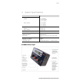
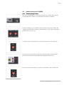
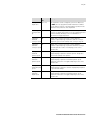
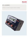
CS 430RC
Solid De-icer Controller Configuration and Set-up Manual
2/17
Table of Contents
1
2
Systems Modes of Operation
System Features
3
4
3
4
5
6
4.1
System Description
System Specifications
CS-430RC Dial and Button Functions
4.2
Commissioning the CS-430RC
8
4.2.1
Commissioning Procedure
8
4.3
Parameter Description
9
5
5.1
Programming and Setting Up the System
Quick Set-up Guide
12
12
5.2
Nulling of the Solenoids
12
7
5.2.1
Nulling the Solenoid and Engine RPM
12
5.2.2
Manually Nulling the Solenoid and Setting the Minimum
12
5.2.3
Manually Nulling the Solenoid and Setting the Maximum
Conveyor Speed
12
Conveyor Speed
5.2.4
Nulling the Solenoid and Setting the Minimum & Maximum
13
Spinner Speeds
5.2.5
Nulling the Solenoid and Setting the Minimum & Maximum
13
Spinner Speeds
5.3
Ground Speed Calibration
13
5.3.1
Overview
13
5.3.2
Auto-calibration Using the Vehicle's Speedometer
14
5.3.3
Auto-calibration Using a Hand Held GPS Unit
14
5.3.4
Auto-calibration of Ground Speed
14
5.4
Material Calibration
14
5.5
Liquid Calibration
15
6
Error Messages
16
Bosch Rexroth Canada Corp. reserves the right to revise this information at any time and for
any reason and reserves the right to make changes at any time, without notice or obligation,
to any of the information contained in this piece of literature.
Please check for updates at: www.boschrexroth.ca/compu-spread
Bosch Rexroth Canada ı 16.10.2008 ı Revision 2.2
3/17
1
System Modes of Operation
The CS-430RC Controller allows for 7 modes of operation.
Manual Mode
This mode allows the driver to manually control the spread rate. Each setting on the
spinner/Conveyor Dial is a percentage of maximum null setting. There are 9
configurable application rate settings. The display will show “M” on the screen.
12 Volt Triggered Manual
Man ual Mode
In addition to manual mode operation, this mode allows the controller to start and
stop the spreader based on a 12V signal. The display will show “V” on the screen.
Ground Speed Triggered Manual Mode
In addition to manual mode operation, this mode will start and stop the spreader
based on ground speed input. The display will show “G” on the screen.
Open Loop Mode
This mode utilizes the ground speed sensor only to regulate the amount of material
that will be dispensed off the vehicle. There are 9 configurable application rate
settings available. The display will show “O” on the screen.
Closed Loop Mode
This mode utilizes both the conveyor and ground speed sensors to regulate the
amount of material that will be dispensed off the vehicle. There are 9 configurable
application rate settings available. The display will show “C” on the screen.
Fixed Mode (liquid only)
In this mode the liquid output will be an on/off signal. When the liquid dial is set to
any position other than 0 there will be an output. (Used for fixed ratio wet power
units.)
AntiAnti- ice (liquid only)
In this mode the liquid will be closed loop and displayed in gallons/liters per
mile/kilometer. The conveyor dial and display is disabled but the spinner remains
active.
Bosch Rexroth Canada ı 16.10.2008 ı Revision 2.2
4/17
2
System Features
The CS-430RC features include:
•
ON-OFF switch with Power indicator
•
Spinner rate control
•
Conveyor/Auger application rate control
•
Conveyor feedback “closed loop” control
•
Liquid application rate control
•
Liquid feedback “closed loop” control
•
Conveyor and liquid auto-nulling
•
Programmable spinner operation during selected operational modes
•
Blast function
•
Pause function
•
Remote Pause/Blast
•
Stationary Unload function
•
Auger/Conveyor Reverse Function
Bosch Rexroth Canada ı 16.10.2008 ı Revision 2.2
5/17
3
System Description
The CS-430RC is an advanced three knob control system that utilizes the Rexroth
RC-2/2 electronic mobile controller to drive Spinner/Conveyor outputs. The RC-2/2
features current and voltage compensation of output signals preventing output
fluctuations.
In addition, a separate remote user interface incorporating a backlit LCD display
offers visual indication of 5 selectable operating modes, spread-width, vehicle
speed and application rates.
Audible and Text based error messages provide live operating status of the
controller and auxiliary system functions. This includes auto-detection of cable,
valve and/or sensor malfunction.
Detented/latched control knobs and tactile buttons allows for user-friendly
operation. Configuration is easily accomplished with 2 front mounted tactile buttons
allowing easy menu navigation of the set-up parameters. The set-up menu is
accessible using a key-switch.
The Auto-nulling feature allows for easy valve set-up. Manual nulling is also available.
Bosch Rexroth Canada ı 16.10.2008 ı Revision 2.2
6/17
4
System Specifications
Specifications
Dimensions (approx.):
Display
Microcontroller
W – 7” (180mm)
H – 4.75” (120mm)
D – 2.75” (70mm)
W – 8” (204mm)
H – 1.6” (41mm)
L – 4.5” (114mm)
Weight:
Display
Microcontroller
3.3 LB (1.5 kg)
1.2 LB (0.5 kg)
Input Voltage
8-28 Volts
Proportional Valve Outputs
On/Off Valve Outputs
Speed Inputs
3 (Spinner, Conveyor, and Liquid)
1 (Auger Reverse)
3 (Vehicle Speed, Conveyor Speed and Liquid
Flow)
Max Current per Output
PWM Dither Frequency
Speed Input Limits
2.3 AMPS
100 Hz
PNP, NPN and Hall effect – 0...10k Hz > 1V rms.
CSCS- 430RC Front Face Layout
Bosch Rexroth Canada ı 16.10.2008 ı Revision 2.2
7/17
4.1
CS-430RC Dial and Button Functions
OnOn- Off Switch
Powers up the controller.
Spinner – Auger/Conveyor Dials – Liquid Dials
Control the rates of the Auger/Conveyor, spinner(s) and liquid pump. Both
spinner and conveyor dials are used for parameter selection while in
programming mode.
Blast Mode
Increases the spread rate for heavy duty application needs. Blast is activated by
pressing the conveyor dial. The blast rate is user configurable.
Pause Mode
To temporarily pause the conveyor and/or liquid functions while spreading.
Pause is activated by pressing the Spinner dial.
Stationary Unload
To unload remaining material after completion of the spreading operation,
stationary unload may be activated by pressing both the conveyor and the
spinner dials simultaneously. Conveyor, liquid and spinner functions can be
adjusted between min and max output by adjustment of the appropriate
function dial.
Tactile Buttons
These up and down select buttons are used in parameter adjustment and some
operator functions. Push the up button to see actual conveyor rate, and press
the down button for the conveyor set-point. The actual rate will show the
conveyor fluctuations, while the set-point will display the dial setting in lb/mile
or kg/km.
Reverse Function
To reverse the auger/conveyor while in the operational mode, press both Tactile
Select keys at the same time.
Programming Key
A programming key is provided for controller set-up.
Remote
Remote Pause/Blast
A remote pause/blast activation switch can be connected from the rear of the
controller using an available remote pause/blast cable kit.
Bosch Rexroth Canada ı 16.10.2008 ı Revision 2.2
8/17
4.2
Commissioning the CS-430RC
4.2.1 Commissioning Procedure
Once the programming key is inserted and turned, the controller will enter into
programming mode and the screen will display the parameter numbers.
Parameter numbers are selectable by using the spinner and conveyor dials. (For
example, setting the spinner dial to 3 and setting the conveyor dial to 5 will show
parameter 35 on the screen.)
To edit the value of a parameter press the Conveyor dial to go into edit mode.
To edit the selected parameter value, press either the upper or lower selector
button. The new parameter value will now be displayed on the screen.
Press the Conveyor Dial again to accept the new parameter and exit edit mode.
Bosch Rexroth Canada ı 16.10.2008 ı Revision 2.2
9/17
4.3
Parameter Description
Function
Parameter
No.
Description
Setting the
spread rates
1 to 9
Nine spread rates can be configured. The rate programmed
under Parameter 1 will be the rate under position 1 of the
conveyor dial in operation mode. Parameter 9 is position 9 of
the conveyor dial.
Setting the
spinner speed
11 to 19
Nine spinner speeds can be configured. The rate programmed
under Parameter 11 will be the rate under position 1 of the
spinner dial in operation mode. Parameter 19 is position 9 of
the spinner dial.
Selection of
Solid control
mode
20
Allows the selection of one of five control modes:
“Manual”, “12V triggered”, “Ground speed triggered”,
“Open Loop” and “Closed loop”. See page 3 for a more indepth description of operation.
• Toggle the power on and off to accept the control mode
change.
Conveyor
Autonull
21
Used to automatically set the minimum and maximum valve
setting on the conveyor. Available in closed loop mode.
Calibrating
solid material
22
Material calibrations. See “calibration procedure” on page 14.
Weight per
minute at max
speed
23
The result of the calibration process in LBS or Kg per minute
is shown here. This value represents the maximum material
dispensed per minute. Available in open loop mode.
Weight per
revolution of
conveyor
24
The result of the calibration process in LBS or Kg per
revolution is shown here. Available in closed loop mode.
Selection of
Liquic control
mode
25
Allows the selection of one of five control modes:
“Manual”, “12V triggered”, “Ground speed triggered”,
“Open Loop”, “Closed loop”, “Fixed” and “Anti-ice”. See
page 3 for a more in-depth description of operation.
• Toggle the power on and off to accept the control mode
change
Liquid autonulling
26
Used to automatically set the minimum and maximum valve
settings of the liquid pump. Available in closed-loop mode.
Liquid
calibration
27
Material calibrations. See “Calibration procedure“ on page 14.
Pulses per
liquid volume
28
The result of the calibration process gallons or litres per
revolution is shown here. Available in closed-loop and anti-ice
mode.
Blast Alarm seconds
33
This parameter set the time allowed in Blast mode before an
alarm sounds. 0 = disabled 0-300 seconds, default = 15
seconds.
Bosch Rexroth Canada ı 16.10.2008 ı Revision 2.2
10/17
Function
Parameter
No.
Description
Blast mode
34
Sets the mode for the Blast feature
Manual – The conveyor will output a percentage of maximum
as set in P39.
Auto – The conveyor will output the rate set in P38.
Note: The blast mode will be the same as the control mode
set in P20.
Spinner stop or 35
no stop
Sets the action of the spinner.
Never – Spinner will always turn when the dial is set.
Speed – Spinner will start and stop with ground speed.
Pause – Spinner will only stop when the pause button is
pressed.
Speed & Pause – Spinner will stop with ground speed
and the pause button.
Conv. Pulses
per rev.
36
This value is the number of pulses generated by the conveyor
motor feedback sensor with every rotation.
CLP blast
38
Determines the conveyor output in LB’s/mile or kg/km while
the conveyor is in closed loop mode. Do not exceed maximum
application rate setting. (Parameter 9)
Blast mode
rate
39
The number shown here is the percentage of maximum
conveyor output speed at which the system will operate while
in manual Blast mode.
Calibrating the
ground speed
44
Ground speed calibration – see calibration procedure on page
13.
Ground Speed
pulses per Km
or Mile
45
The number of Pulses per Kilometer or Mile produced by the
ground speed sensor. This parameter is calculated by the
controller during the calibration process and requires no
adjustment. (Please see page 14 for further discussion.)
Over-speed
alarm
46
A warning buzzer will sound when the vehicle speed exceeds
set value in MPH or KM/H. (Set the parameter to 0 to turn
function off.)
System Units
57
This parameter selects either metric (0) or imperial (1)
operation.
System
language
58
This parameter selects the language; (0) for English and (1)
for French.
Resetting all
parameters
59
Resets all parameters to factory default settings.
Bosch Rexroth Canada ı 16.10.2008 ı Revision 2.2
11/17
Function
Parameter
No.
Description
Setting the
liquid rates
70 to 79
Nine liquid rates can be configured. (L/Tonne or Gal/Ton as
per P57.
P57.) The rate programmed under Parameter 70 will be
the rate under position 1 of the liquid dial in operation mode.
Parameter 79 is position 9 of the liquid dial.
Enhancing
Conveyor start
up
80
Conveyor Forward Gain provides an additional output to the
conveyor on startup. This feature overcomes initial inertia and
friction at startup, allowing for an even distribution of
material from a stopped position.
Setting the
81
minimum
conveyor speed
Nulling of the conveyor solenoid to set the minimum
controller output amperage required to start the conveyor.
Required to get a smooth startup of the conveyor. Page 12.
Setting the
82
maximum
conveyor speed
Nulling of the conveyor solenoid to set the maximum
controller output amperage required for maximum conveyor
speed. Required to reduce over-amperage to the coil to
extend its life.
Setting the
minimum
spinner speed
83
Nulling of the spinner solenoid to set the minimum controller
output amperage required to start the spinner. Required to
get a smooth startup of the spinner.
Setting the
maximum
spinner speed
84
Nulling of the spinner solenoid to set the maximum controller
output amperage required for maximum spinner speed.
Required to reduce the over applied amperage to the coil to
extend its life.
Setting the
85
minimum liquid
speed
Nulling of the liquid solenoid to set the minimum controller
output amperage required to start the liquid pump. Required
to get a smooth startup.
Setting the
maximum
liquid speed
Nulling of the spinner solenoid to set the maximum controller
output amperage required for maximum spinner speed.
Required to reduce the over applied amperage to the coil to
extend its life.
86
Bosch Rexroth Canada ı 16.10.2008 ı Revision 2.2
12/17
5
5.1
Programming and Setting Up the System
Quick Set-up Guide
•
Insert programming key and turn to activate program mode
•
Set the units of measure – either imperial or metric using P57
•
Set the desired material application rates using P1 through 9
•
Set the desired liquid rates using P70-79
•
•
Set the desired operating control mode of the solid using P20 – toggle the
power on and off to accept the control mode change
Set the desired operating control mode of the liquid using P25 – toggle the
power on and off to accept the control mode change
Set the desired material output while in the BLAST mode using P38 or 39
•
Set the desired “Spinner Stop” mode using P35
•
5.2
Nulling of the Solenoids
5.2.1 Nulling the Solenoids and Engine RPM
Note: Depending on hydraulic pump size, it may be necessary to increase the engine
RPM to approximately 1500 RPM during the nulling procedure, in order to ensure
sufficient oil flow.
If the conveyor is in closed loop mode and equipped with a feedback sensor, use of
the auto-nulling feature in P21 is desired.
•
Set the controller to P21
Press the Conveyor Dial to activate this parameter
•
Press the UPPER SELECT KEY and the auto null sequence will begin
•
•
When finished (approximately 90 seconds) press blast to exit and store this
parameter
5.2.2 Manually Nulling the Solenoid and Setting the Minimum Conveyor Speed
•
Set the controller to P81
•
Press the Conveyor Dial to activate this parameter
•
Press the UPPER SELECT KEY until the conveyor starts to turn
•
Press the LOWER SELECT KEY in small increments until the conveyor stops
•
Press the Conveyor Dial to lock in the setting
5.2.3
Manually
ally Nulling the Solenoid and Setting the Maximum Conveyor Speed
5.2. 3 Manu
•
Set the controller to P82
•
•
Press the Conveyor Dial to activate this parameter
Press the UPPER or the LOWER SELECT KEY until the conveyor is running at the
maximum hydraulic motor speed. Observe RPM in closed loop mode displayed
on the screen
Bosch Rexroth Canada ı 16.10.2008 ı Revision 2.2
13/17
•
Press the Conveyor Dial to lock in the setting
5.2.4 Nulling the Solenoid and Setting the Minimum & Maximum Spinner
Speeds
•
Following the same procedure above for the conveyor, set the minimum and
maximum spinner speed using P83 and 84
5.2.5
5.2. 5 Nulling the Solenoid and Setting the Minimum & Maximum Liquid
Speeds
If the liquid pump is in closed loop mode and equipped with a feedback sensor, use
the auto-nulling feature in P26.
•
•
•
•
Set the controller for P26
Press the Conveyor Dial to activate this parameter
Press the UPPER SELECT KEY and the auto null sequence will begin
When finished (approximately 90 seconds) press blast to exit and store this
parameter
Follow the same procedure as the spinner if no sensor is present using P85 and 86.
86
5.3
Ground Speed Calibration
5.3.1 Overview
The CS-430RC Controller determines ground speed by monitoring the pulses it
receives from the ground speed sensor mounted in the vehicle transmission. This
sensor is the same sensor providing the vehicle’s odometer with the necessary input
for the odometer to have the ability to indicate speed and distance.
In order for the CS-430RC to have the ability to calculate ground speed and distance
it must first be accurately calibrated. The process of calibration tells the CS-430RC
exactly how many pulses per KM or Mile it will receive from the transmission
mounted sensor.
The process of calibration needs to be completed for each vehicle, as each
vehicle’s system is not exactly the same.
same. Discrepancies may occur due to sensor
mounting differences, tire sizes differences etc. thus calibrating each vehicle
independently is the only way of ensuring accuracy.
Listed below are the most common techniques for calibrating the ground speed
input.
1.
Auto-calibration to the vehicle’s speedometer. By driving the vehicle at a
predetermined speed using the vehicle’s speedometer as the speed indicator.
The accuracy level is only as accurate as the speedometer calibration. During
the calibration process the CS-430RC will determine the pulses per KM or Mile;
this count will be reflected on the “Speed input” screen once the auto
calibration process has been completed.
Bosch Rexroth Canada ı 16.10.2008 ı Revision 2.2
14/17
If the speedometer is inaccurate you may use a GPS unit to determine vehicle speed
as described below.
2.
Auto-calibration to a hand held GPS unit. By driving the vehicle at a
predetermined speed using a handheld GPS unit as the speed indicator. Using a
hand held GPS unit will result in greater accuracy then using the vehicle
speedometer. The accuracy level is only as accurate as the GPS Unit’s
calibration. During the calibration process the CS-430 will determine the pulses
per KM or Mile; this count will be reflected on the “Speed input” screen once
the auto calibration process has been completed.
5.3.2 Auto
Auto--calibration Using the Vehicle's Speedometer
•
Follow the auto calibration procedure below, hold the vehicle speed to the
speed indicated on the vehicle’s speedometer
5.3.3 AutoAuto- calibration Using a Hand Held GPS Unit
•
Follow the auto calibration procedure below, hold the vehicle speed to the
speed indicated on the GPS unit
5.3.4 Auto
Auto--calibration of Ground Speed
•
Set the controller to P44
•
Press the Conveyor Dial
•
Set the speed at which the vehicle will be moving during the calibration process
using the SELECT keys. For example 30 mph or km/h
•
Drive the vehicle at the speed set above
•
Once the vehicle speed is stable, press the conveyor dial
•
The setting will be locked in
If verification of the controller ground speed reading indicates that the controller
ground speed does not closely match, an adjustment in the Pulses per Kilometer or
Pulses per Mile can be made using P45.
P45
5.4
Material Calibration
•
Load the vehicle hopper with the material to be calibrated
•
Set the Hopper Gate to the desired opening
•
Operate the vehicle engine at 1500 RPM
•
•
Set the controller to P22 and Press the Conveyor Dial
Press the UPPER SELECT key to start the calibration process
•
Allow the material to discharge for 1 minute
•
Press the UPPER SELECT key to stop the material discharge
•
Weigh the material discharged during the calibration process, and enter this
weight using the SELECT keys
•
Press the Conveyor Dial to accept the value entered
Bosch Rexroth Canada ı 16.10.2008 ı Revision 2.2
15/17
The resulting “Weight per minute” calibration measurement can be seen in P23
(open loop control).
The resulting “Weight per revolution” calibration measurement can be seen in P24
(closed loop control).
If verification of the “Material calibration” indicates that the calibration is
inaccurate, an adjustment can be made using P23 or P24
P24. If the discharge weight is
lower than expected set P23/P24
P23/P24 lower, if the discharge weight is higher than
expected set P23/P24
P23/P24 higher.
5.5
Liquid Calibration
•
Fill the liquid reservoir with the liquid to be calibrated
•
Operate the vehicle engine at 150 RPM
•
Set the controller to P27 and Press the Conveyor Dial
Press the UPPER SELECT key to start the calibration process
•
•
Allow the liquid to discharge for exactly one (1) minute
•
Press the UPPER SELECT key to stop the liquid discharge
•
Measure the liquid discharged during the calibration process and enter the
volume using the SELECT keys
•
Press BLAST to accept this value
If verification of the “Material calibration” indicates that the calibration is
inaccurate, an adjustment can be made using P28.
P28 If the discharge weight is lower
than expected set P28 lower, if the discharge weight is higher than expected set
P28 higher.
Bosch Rexroth Canada ı 16.10.2008 ı Revision 2.2
16/17
6
Error Messages
The error message will be displayed on the screen and a buzzer will sound for a few
seconds, and will automatically disappear without operator input.
•
Set Dials to zero – This prevents accidental start-up of the system once the
controller is powered up. The operator needs to set all dials to zero before
power-up.
•
Speed calibration – An error occurred during the ground speed calibration
process. (No feedback signal detected.)
•
Spinner calibration – The minimum and maximum null settings are too close for
proper operation or the maximum value is lower than the minimum.
•
Conveyor calibration – The minimum and maximum null settings are too close
for proper operation or the maximum value is lower than the minimum.
•
•
Liquid volume calibration – No feedback detected or the volume is set to zero.
Liquid calibration – The minimum and maximum null settings are too close for
proper operation or the maximum value is lower than the minimum.
•
Weight calibration – No feedback detected or the weight is set to zero.
•
Potentiometer failure – The spinner, conveyor or liquid dials are malfunctioning;
or the cable is damaged.
•
Auto-null error – No feedback detected or controller not in closed loop mode.
Bosch Rexroth Canada ı 16.10.2008 ı Revision 2.2
17/17
Notes:
Bosch Rexroth Canada ı 16.10.2008 ı Revision 2.2