1
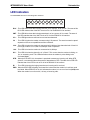
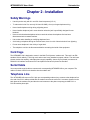
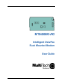
MT5600BR-V92
Intelligent Data/Fax
Rack Mounted Modem
User Guide
MultiModem®II User Guide
MT5600BR-V.92
P/N S000392B Revision B
All rights reserved. This publication may not be reproduced, in whole or in part, without prior expressed
written permission from Multi-Tech Systems, Inc.
Copyright © 2006-7 by Multi-Tech Systems, Inc.
Multi-Tech Systems, Inc. makes no representations or warranties with respect to the contents hereof
and specifically disclaims any implied warranties of merchantability or fitness for any particular purpose. Furthermore, Multi-Tech Systems, Inc. reserves the right to revise this publication and to make
changes in the content hereof without obligation of Multi-Tech Systems, Inc. to notify any person or organization of such revisions or changes.
Record of Revisions
Revision Date
Description
A
B
04/14/06
04/19/07
Manual released.
Update the Technical Support contact list.
Trademarks
MultiModemII, Multi-Tech, and the Multi-Tech logo are trademarks of Multi-Tech Systems, Inc.
Microsoft, Windows, Windows XP is a trademarks of Microsoft Corporation in the United States and/or
other countries. All other trademarks are owned by their respective companies.
Patents
This device is covered by one or more of the following patents: 6,031,867; 6,012,113; 6,009,082;
5,905,794; 5,864,560; 5,815,567; 5,815,503; 5,812,534; 5,809,068; 5,790,532; 5,764,628; 5,764,627;
5,754,589; 5,724,356; 5,673,268; 5,673,257; 5,644,594; 5,628,030; 5,619,508; 5,617,423; 5,600,649;
5,592,586; 5,577,041; 5,574,725; 5,559,793; 5,546,448; 5,546,395; 5,535,204; 5,500,859; 5,471,470;
5,463,616; 5,453,986; 5,452,289; 5,450,425; 5,355,365; 5,309,562; 5,301,274. Other patents pending.
World Headquarters
Multi-Tech Systems, Inc.
2205 Woodale Drive
Mounds View, MN 55112
Phone (763)785-3500 or (800)328-9717
Fax (763) 785-9874
Technical Support
Country
France:
Europe, Asia, Africa:
U.S., Canada, all others:
By Email
[email protected]
[email protected]
[email protected]
Internet http://www.multitech.com
By Phone
+(33) 1-64 61 09 81
+(44) 118 959 7774
(800) 972-2439 or (763) 785-3500
MT5600BR-V92 User Guide
Contents
Contents
Chapter 1 - Introduction .......................................................................................................... 5
Product Description ........................................................................................................................... 5
General features ............................................................................................................................... 5
LED Indicators .................................................................................................................................. 6
Technical Specifications .................................................................................................................... 7
Chapter 2 - Installation ............................................................................................................ 9
Safety Warnings ................................................................................................................................ 9
Card Cage ......................................................................................................................................... 9
Serial Cable ...................................................................................................................................... 9
Telephone Line ................................................................................................................................. 9
PC Board Controls .......................................................................................................................... 10
DIP-Switch Settings ........................................................................................................................ 10
OOS (Busy Out) Toggle Switch ....................................................................................................... 12
Out of Service/Test Jumper ............................................................................................................ 12
Dial-Up and Leased Lines ............................................................................................................... 12
Installation ....................................................................................................................................... 13
Chapter 3 - Configuration ...................................................................................................... 14
Configuring Your Software .............................................................................................................. 14
ConfiguringSoftware for Your Modem ............................................................................................. 14
PC Initialization Strings ................................................................................................................... 14
Changing Default Parameters ......................................................................................................... 15
Macintosh Initialization .................................................................................................................... 15
Chapter 4 - AT Commands .................................................................................................... 16
Fax Commands ............................................................................................................................... 16
Chapter 5 - Warranty and Repairs ........................................................................................ 17
Multi-Tech Warranty Statement ....................................................................................................... 17
Repair Procedures for U.S. and Canadian Customers .................................................................... 17
Repair Procedures for International Customers .............................................................................. 18
Repair Procedures for International Distributors .............................................................................. 18
Replacement Parts .......................................................................................................................... 18
Appendix A - Regulatory Compliance .................................................................................. 19
FCC Part 68 Telecom ..................................................................................................................... 19
FCC Part 15 .................................................................................................................................... 20
Fax Branding Statement .................................................................................................................. 20
Canadian Limitations Notice ............................................................................................................ 20
Industry Canada .............................................................................................................................. 21
EMC, Safety, and R&TTE Directive Compliance ............................................................................. 21
International Modem Restrictions .................................................................................................... 21
New Zealand Telecom Warning Notice ........................................................................................... 21
iii
MT5600BR-V92 User Guide
Contents
Appendix B - Updating Your Modem’s Firmware ............................................................... 23
Introduction ..................................................................................................................................... 23
Upgrade Overview .......................................................................................................................... 23
Appendix C - ASCII Conversion Chart ................................................................................. 26
Appendix D – Waste Electrical and ...................................................................................... 27
Electronic Equipment (WEEE) .............................................................................................. 27
Index ........................................................................................................................................ 28
iv
MT5600BR-V92 User Guide
1 Introduction
Chapter 1 - Introduction
Congratulations on your purchase of the MultiModem® II intelligent data/fax modem, model MT5600BR-V92.
You have acquired one of the finest internal data/fax modems available today from one of the world’s
oldest modem manufacturers: Multi-Tech Systems, Inc. This User Guide will help you to install, configure,
test, and use your modem.
Product Description
The MT5600BR-V92 incorporates ITU-T V.92 protocol which provides quick connections, downstream
transmissions at speeds up to 56K bps*, and upstream transmissions at speeds up to 48K bps when
connected to V.92-compatible Internet service providers. Transmissions between the MT5600BR-V92 and
other client modems are limited to 33.6K bps, as are upstream transmissions to non-V.92-compatible
ISPs and downstream transmissions that are converted more than once on the telephone network.
Fax Communications: Supports Class 1, 1.0, and Class 2 faxing at 14.4K bps.
Features: Modem features include automatic fallback to slower speeds in noisy line conditions, and fall
forward to faster speeds as conditions improve. Can autodial, redial, pulse (rotary) and touch-tone dial.
Detects dial tones and busy signals for reliable call-progress detection. Compatible with the standard AT
command set used by most communication programs.
NOTE:
* Though this modem is capable of 56K bps download performance, line impairments, public telephone
infrastructure, and other external technological factors currently prevent maximum 56K bps connections.
General features
• Supports V.92/56K download speeds and 48K upload speeds when connecting with V.92 server
• Automatic fallback to slower speeds in noisy line conditions, and fall forward to faster speeds as
conditions improve.
• Serial port data rates adjustable to 115.2K bps
• ITU V.42 LAP-M and MNP Class 3 and 4 error correction
• ITU V.42bis (4-to-1), ITU V.44bis (6-to-1), and MNP 5 (2-to-1) data compression
• Automatic disabling of compression when transferring already compressed files
• Autodial, redial, pulse (rotary), and touch-tone dial
• Dial tone and busy signal detection for reliable call-progress detection
• Distinctive ring support to route data or fax calls on a single phone line
• FlashROM upgradable (customer upgradable in a Windows environment)
• Compatibility with the standard AT command set used by most communication programs
• Nonvolatile memory for storage of customized modem parameters and ten telephone numbers
Fax
• Responds to Class 1, 1.0, and Class 2 fax commands, enabling it to exchange editable and
encrypted faxes with other Windows computers
• Sends and receives faxes from your computer at 14,400 bps, 9600 bps, 7200 bps, 4800 bps, 2400
bps, or 300 bps
5
MT5600BR-V92 User Guide
1 Introduction
LED Indicators
The MT5600BR-V92 has ten LED diagnostic indicators.
RCV
XMT
CO
56
33.6
14.4
OH
DTR
RI
ERR
RCV - This LED blinks when data is being received, on for a space, off for a mark. The state of this
RCV LED matches that of the RCV circuit on Pin 3 of the RS232C/V.24 interface.
XMT - This LED blinks when data is being transmitted, on for a space, off for a mark. The state of
this LED matches that of the XMT circuit on Pin 2 of the RS232C/V.24 interface.
CO - This LED lights when a valid carrier tone has been detected.
56
- This LED is lit when the modem connects using V.92 protocol. The actual connection speed
depends on ISP server capabilities and line conditions.
33.6 - This LED is lit when the modem is connected at 33,600 bps. Note that when both 33 and 14
LEDs light, modem is in 16,800 to 33,600bps mode of operation.
14.4 - This LED is lit when the modem is connected at 14,400 bps.
OH - This LED is lit when the phone line is “off hook”. This occurs when the modem is dialing, on
line, or answering a call. The LED also flashes when the modem is pulse dialing in the
Command Mode.
DTR - When the DTR LED is lit, the modem is permitted to answer an incoming call. When DTR
goes off, a connected modem disconnects if dependent on DTR. The state of this DTR LED
matches that of the DTR circuit on Pin 20 of the RS232C/V.24 interface.
RI
- This LED is lit during the ringing interval as an incoming call is received.
ERR - When the ERR LED is flashing, the leased line is down and the modem is in self-test mode
has failed. When ERR LED is on, this indicates the modem is in an out of service (OOS) state.
When the modem is out of service, it is busy to incoming calls.
6
MT5600BR-V92 User Guide
1 Introduction
Technical Specifications
Your MT5600BR-V92 data/fax modem meets the specifications listed below:
Model Number
MT5600BR-V92
Server-to-Client
Data Rates
V.90 speeds when accessing a V.90 or V.92 server (actual
speed depends on server capabilities and line conditions)*
Client-to-Server
Data Rates
Up to 50Kbps when accessing a V.92 server (actual speed
depends on server capabilities and line conditions); other
wise, the same as client-to-client data lines.
Client-to-Client
Data Rates
33600,31200, 28800, 26400, 24000, 21600, 19200, 16800,
14400, 12000, 9600, 7200, 4800, 2400, 1200, 0-300 bps
Fax Data Rates
14400, 12000, 9600, 7200, 4800, 2400, 1200, 0-300 bps
Data Format
Serial, binary, asynchronous, synchronous
Modem Compatibility
ITU-T V.92, V.90, V.34 enhanced, V.34, V.34bis, V.32,
V.22bis, V.22; Bell 212A and 103; ITU-T V.21; V.42,
V.42bis, V.44, V.25bis
Fax Compatibility
T.4, T30, V.21, V.27ter, V.29, V.34, V.17; TIA/EIA 578 Class
1, 1.0, 2, TR29.2
Video Compatibility
ITU-T V.80 for H.34 video conferencing
Error Correction
ITU-T V.42 (LAP-M or MNP 4)
Data Compression
ITU-T V.44 (6:1 throughput), V.42bis (4:1 throughput), MNP
5 (2:1 throughput)
Speed Detection
Automatic speed detection and switching between available
speeds
Speed Conversion
Serial port data rates adjustable to 300; 1200; 2400; 4800;
9600; 19,200; 38,400; 57,600; 115,200 bps
Mode of Operation
Full duplex data over dial-up line, 2-wire and 4-wire lease
line; automatic or manual dialing, automatic or manual
answer
Flow Control
XON/XOFF (software), RTS/CTS (hardware)
Intelligent Features
Full AT command compatible, redial, repeat dial, pulse or
tone dial, dial pauses, auto answer, adaptive answer; EIA
extended automode; adaptive line probing; automatic
symbol and carrier frequency during start-up, retrain and
rate renegotiation, DTMF detection, call status display, autoparity and data rate selections, keyboard-controlled modem
options, non-volatile memory, quick-connect startup
*Though these modems are capable of 56K bps download performance, line impairments,
public telephone infrastructure and other external technological factors currently prevent
maximum 56K bps connections.
7
MT5600BR-V92 User Guide
1 Introduction
Command Buffer
60 Characters
Transmission Level
-11 dBm (dial-up), -15dBm (lease line); dBm level selectable
with DIP-Switch #3 in lease line setting
Frequency Stability
±0.01%
Receiver Sensitivity
-43 dBm under worst-case conditions
AGC Dynamic Range
43 dB
Interface
EIA RS232C/ITU-TSS V.24
Diagnostics
Power-on Self Test and Local analog loop
Environmental
Temperature range 0°–50°C (32°–120°F);
humidity range 20–90% (non-condensing)
Storage Temperature
-10° to +85°C (14°- 185° F)
Dimensions
10½ wide x 5½ long
Weight
8 oz
Operating Systems
Tested for use with Windows 98, NT, 2000, XP, 2003 Server
and Linux (2.2.x kernal)
Limited Warranty
10 years
8
MT5600BR-V92 User Guide
1 Introduction
Chapter 2 - Installation
Safety Warnings
•
•
•
•
Use this product only with UL- and CUL-listed computers (U.S.A.)
To reduce the risk of fire, use only UL-listed 26 AWG (.41mm) or larger telephone wiring.
Never install telephone wiring during a lightning storm.
Never install a telephone jack in a wet location unless the jack is specifically designed for wet
locations.
• Never touch uninsulated telephone wires or terminals unless the telephone line has been
disconnected at the network interface.
• Use caution when installing or modifying telephone lines.
• Avoid using a telephone during an electrical storm; there is a risk of electrical shock from lightning.
• Do not use a telephone in the vicinity of a gas leak.
• The telephone cord is to be disconnected before accessing the inside of the equipment.
Card Cage
The MT5600BR-V92 is designed to mount in the Multi-Tech Systems' modem rack. This rack is an EIAstandard 19-inch wide by 7-inch high rack, and mounts in any standard computer cabinet. The rack has a
sixteen modem slot capacity, redundant power supply capability, sixteen 25-pin (female) connectors for
RS232C/V.24 interface and sixteen RJ11 back-plane connectors for phone line interface.
Serial Cable
You must provide a serial cable to connect each corresponding MT5600BR-V92 to your computer. The
cable must have a DB-25 male interface into the modem rack.
Telephone Line
The MT5600BR-V92 uses one RJ11 jack per corresponding modem slot to connect to the telephone line.
One end of the RJ11 cable provided with the modem connects the rack's RJ11 connector (located on the
back plane of the modem rack) and the other end connects to the phone-company-provided RJ11 or
RJ11W modular phone jack.
9
MT5600BR-V92 User Guide
1 Introduction
PC Board Controls
The MT5600BR-V92 is designed on a single printed circuit board. This board contains sixteen DIPSwitches. There is a two-position"Out of Service" (OOS) toggle switch that extends from the front of the
modem circuit card. There is also a two-position TEST/OOS berg jumper located towards the back and
center of the card.
The sixteen DIP-Switches and berg jumper control various modem options or set default values for the
MT5600BR-V92 Command mode. There is a difference in how several of the switches operate depending
on whether you are in synchronous or asynchronous mode (DIP-Switch #12).
Most communications software packages have installation procedures of their own, which call for certain
modem DIP-Switch settings. If you are using such a package, follow the software's instructions.
DIP-Switch Settings
The vast majority of installations are similar, with the MT5600BR-V92 being used to dial up a remote
installation where the call is automatically answered. The factory default DIP-Switch settings are based
on this assumption. The following is a brief description and summary of the MT5600BR-V92's DIP-Switch
options:
Switch Function
#1
DTR Forced/
DTR from Interface *
Position
UP*
DOWN
Effect
DTR dependent on interface
DTR forced ON at all times
#2
Flow Control &E4*
UP*
(Async/Dial-Up/Leased Line) DOWN
Hardware flow control
Software flow control
#2
SDLC*/BSC (Sync)
UP*
DOWN
SDLC mode
BSC mode
#3
Result Codes Enabled*
(Async Dial-up)
UP
DOWN*
Q1 Disable Responses
Q0 Enable Responses
#3
DbM Transmit -15dB/-11dB*
(Async/Sync/Leased Line)
UP
DOWN*
Lease Line
transmits at -11dB
#4
No affect in async
#4
AS/400 Mode Disabled*
(Sync Dial-Up/Leased Line)
UP*
DOWN
AS/400 Mode OFF
AS/400 Mode ON
#5
Auto-Answer Enabled*
(Async/Sync/Dial-Up)
UP*
DOWN
Enable Auto Answer
Disable Auto Answer
* Factory default setting.
10
MT5600BR-V92 User Guide
2 Installation
Switch Function
#5
Answer/Originate*
(Async/Sync/Leased Line)
Position
UP*
DOWN
Effect
Answer Mode
Originate Mode
#6
Max-Throughput Enabled*
(Async/Dial-Up/Leased)
UP*
DOWN
Modem set-up to
operate at highest
efficiency level
#6
Slave Clock Disabled*
(Sync/Dial-Up/Leased)
UP*
DOWN
Slave Clocking OFF
Slave Clocking ON
#7
RTS/Normal/Forced*
(Sync/Async/Dial/Leased)
UP
DOWN*
RTS dependent on interface
RTS forced ON
#8
Command Mode Enabled*
(Sync/AsyncDial/Leased)
UP
DOWN*
Disable Command Mode
Enabled Command Mode
UP*
DOWN
Dial-Up Operation
Lease Line Operation
#9
No affect
#10
Dial-Up*/Leased-Line
#11
No affect in async
#11
Internal*/External Clocking
(Synchronous)
UP
DOWN*
External Clock
Internal Clock
#12
Sync/Async Mode*
UP
DOWN*
Sync Operation
Async Operation
Dip Switch Settings #13 - 16
Switch Position
13/14 UP/UP*
Effect
V.92 Operation (Default)
13/14
DOWN/UP
V.34 Operation
13/14
UP/DOWN
V.32b Operation
13/14
DOWN/DOWN
#15
#15
UP*
DOWN
CD/DSR from Interface
CD/DSR Forced On
#16
#16
UP
DOWN
2-WireOperation
4-Wire Operation
V.22b Operation
* Factory default setting
11
MT5600BR-V92 User Guide
2 Installation
OOS (Busy Out) Toggle Switch
The MT5600BR-V92 contains a two-position OOS switch on the front panel. This switch can be used to
create a “busy out” (OOS) condition for the modem (i.e., take the modem off-hook). To place a modem in
the Busy condition, move the OOS toggle switch to the (BUSY) position. The modem then goes off-hook,
its OOS and OH LEDs light, and incoming calls to this modem get a busy signal. If you suspect a problem
with a particular modem, you can use the BUSY switch to have an optional device (such as a “hunt
group”) that looks for a non-busy line to perform a “roll over” to the next available modem while you check
the status of the Busy modem.
Out of Service/Test Jumper
When the MT5600BR-V92 is Out Of Service (OOS), it is busy to incoming calls. In the Test (default)
setting, the modem drives pin 25 high when the modem is in Test mode. In the OOS (optional) setting, the
computer or terminal forces pin 25 high and puts the modem in a busy condition. Note that jumper
(shorting) plugs are not shipped with the MT5600BR-V92, but is provided by Multi-Tech’s Tech Support
group on request.
J7
J7
P7
Test Setting (Factory Default)
P7
OOS Setting (Optional)
Dial-Up and Leased Lines
Connection to the phone system is made via RJ11 type jacks such as an RJ11C or RJ11W. It can also
be connected to an analog RJ41 or an RJ45S jack, but would not use these jack's digital dB-level
programming features. The MT5600BR-V92 is designed to transmit at a permissive level of -11dB.
To connect the modem to the phone lines, one end of the RJ11 cable that is provided with the modem
plugs into the RJ11 connector located on the back plane of the modem rack and the other end into the
phone-company-provided RJ11 or RJ11W modular phone jack. Make sure that DIP-Switch #10 is in the
UP position (default) when in dial-up mode.
Although the majority of installations involves dial-up lines, the MT5600BR-V92 also connects to two-wire
leased lines (sometimes referred to as dedicated, private, or 3002 lines) and four-wire lease lines.
To connect the modem to leased lines, first determine the type of line termination provided by the phone
company. Most phone companies provide a terminal block with a pair of screws. Some provide a
conventional RJ11 type of connector. If the RJ11 connector is used, you can use the same cable that you
use for dial-up connection. If the screw terminal type connector is used, you may need to order the
#CA167 cable from Multi-Tech Systems.
For a lease line connection, make two DIP-Switch setting changes on the modem's PC board. The first
involves placing DIP-Switch #10 in the DOWN position (changes the modem from dial-up to leased line
operation). The second DIP-Switch change requires that one of the two modems on the leased line circuit
is set to "originate", and the other is set to "answer". To do this, change the setting of DIP-Switch #5.
When you changed the DIP-Switch #10 setting, you also changed the function of DIP-Switch #5. Now the
UP position selects answer mode while the DOWN position selects originate mode. Place DIP-Switch #5
in the UP position on one of the two modems, and on the other modem, place Switch #5 DOWN. It
doesn't matter which is which, just so you have local and remote modems in opposite modes.
12
MT5600BR-V92 User Guide
2 Installation
Installation
Perform the following procedure to install modem cards into the CC1600 rack. The installation process
involves:
1.
Verify that the DIP-Switch settings conform to your application (dial-up or lease line).
2.
Slide a modem card into one of sixteen available modem slots. Start by inserting a modem
into the left-most channel (slot #1) of the rack. The toggle switch should be at the bottom of
the card, with the component side of the card facing the right. The modem’s gold edge connector is offset so that the modem cannot be inserted incorrectly. Continue installing modem
cards as necessary.
3.
Connect one end of an RS232C Cable to the appropriate modem slot (DB25/25-pin connector-female) at the rear of rack. The other end of the RS232C cable is connected to the serial
port of the computer.
Note: Any cables connected to the computer must be shielded to reduce interference.
4.
Plug one end of the RJ11 cable provided with the modem into the rack's RJ11 connector
(located on the back plane of the modem rack) and the other end into the phone-companyprovided RJ11 or RJ11W modular phone jack.
5.
Verify the remote modem's current configuration settings with your MT5600BR-V92 in terms
of data compression, error correction, transmission rate, etc. (Refer to Chapter 4 for AT commands).
6.
Make sure modem and computer/terminal serial port baud rates are adjusted.
7.
Proceed to Chapter 3 of this manual, or to your data communications software manual for
modem configuration.
13
MT5600BR-V92 User Guide
3 Configuration
Chapter 3 - Configuration
Configuring Your Software
Communications software must be configured to work with your modem, your computer, and the
remote system it is calling. Fortunately, most communications programs make the process easy by
providing a default initialization string for your modem as well as defaults for most of the other required
parameters.
Configuring Software for Your Modem
Because remote computers may have different connection requirements such as speed, number of
bits, parity, log-on sequences, etc., communications software is typically configured by sessions, each
session having a unique configuration for a given connection (e.g., to an FTP site or commercial online
service). Most communications programs, however, have a separate modem configuration menu
because modem configurations rarely change from session to session.
The most important configuration is the modem initialization string. This is a sequence of commands
the software uses to configure the modem when the communications software is loaded or when a
session begins. Always begin the initialization string with the ATtention command AT, then follow it with
the modem reset command, &F. Issuing a reset command before other commands ensures that you are
starting with a known state.
The rest of the commands in the initialization string depend on the capabilities of the modem and what
you want it to do. Some older communications programs require you to create the initialization string by
yourself. Most modern communications programs, however, provide you with a ready-made initialization
string that is automatically selected when you choose your modem model from a list. It is a poor idea to
use an initialization string intended for another modem, especially one from another manufacturer,
because modem capabilities and command implementations vary from modem to modem. However, if
your MT5600BR-V92 does not appear on a modem list, you may use the MultiModemII initialization
string.
PC Initialization Strings
We recommend the following initialization string for a MT5600BR-V92 connected to a PC-compatible
computer:
AT &F X4 S0=0 ^M
This string resets the MT5600BR-V92 to the factory default settings, selects extended result codes with
NO DIAL TONE and BUSY, and turns off auto-answer. ^M must end every string sent to the modem from
software. It is the ASCII code for the RETURN key on most keyboards, and the default code for the
carriage return character in the MT5600BR-V92 and most communications programs. The carriage return
character is defined in the MT5600BR-V92 in S-register S3; if you change it, you must also change the
carriage return character code used in your communications software. If you send a command directly to
the modem in terminal mode rather than indirectly through communications software, you must end the
command string by pressing the RETURN key (<CR>) instead of adding ^M to the string.
14
MT5600BR-V92 User Guide
3 Configuration
Changing Default Parameters
The default values for the other parameters in modem configuration menus rarely need changing. They
typically include the dialing prefix (ATDT for touch-tone service and ATDP for rotary service), the dialing
suffix (^M), the hang-up string (+++) ”Response” then (ATH0^M), and response messages (RING, NO
CARRIER, BUSY, etc.). Communications software with a host mode might also include an auto-answer
string (AT S0=1^M).
Macintosh Initialization
Macintosh computers cannot use RTS/CTS hardware flow control without a serial cable wired for
hardware control. The Macintosh 128 and 512 models cannot use RTS/CTS flow control at all. For those
Macintoshes turn off the default RTS/CTS hardware flow control, turn on XON/XOFF flow control, and
ignore DTR:
AT &F X4 &k4 &D0 ^M
For hardware flow control, use the following initialization string:
AT &F X4 &K3 &D0 ^M
Add S0=0 to both strings to disable auto-answer if the MT5600BR-V92 is on a voice line.
You can store the initialization string in nonvolatile memory. With your communications software open and
connected to the modem’s COM port, type the initialization string in the terminal window, substituting a
carriage return for ^M. To store the string, enter
AT &W0 <CR>.
Now you can initialize your modem with the following simple string:
AT Z ^M
15
MT5600BR-V92User Guide
4 AT Commands and Fax Commands
Chapter 4 - AT Commands
A complete AT Commands, S-Registers, and Result Codes Reference Guide can be found on the
MT5600BR-V92 CD and on the Multi-Tech Web site.
Fax Commands
Fax commands resemble AT commands, but are more complicated to use. Because of this, we
recommend that you use a fax program to send and receive faxes rather than attempting to control the
modem directly. Developers who need to know the fax commands for the MT5600BR-V92 can find Fax
Class 1 and Fax Class 2 Reference Guides on the MT5600BR-V92 CD as well as the Multi-Tech Web
site.
16
MT5600BR-V92 User Guide
5 - Warranty and Repairs
Chapter 5 - Warranty and Repairs
Multi-Tech Warranty Statement
Multi-Tech Systems, Inc., (hereafter “MTS”) warrants that its products will be free from defects in material or workmanship for a period of two, five, or ten years (depending on model) from date of purchase, or if proof of purchase is not provided, two, five, or ten years (depending on model) from date of
shipment.
MTS MAKES NO OTHER WARRANTY, EXPRESS OR IMPLIED, AND ALL IMPLIED WARRANTIES OF
MERCHANTABILITY AND FITNESS FOR A PARTICULAR PURPOSE ARE HEREBY DISCLAIMED.
This warranty does not apply to any products which have been damaged by lightning storms, water, or
power surges or which have been neglected, altered, abused, used for a purpose other than the one for
which they were manufactured, repaired by Customer or any party without MTS’s written authorization, or
used in any manner inconsistent with MTS’s instructions.
MTS’s entire obligation under this warranty shall be limited (at MTS’s option) to repair or replacement of
any products which prove to be defective within the warranty period or, at MTS’s option, issuance of a
refund of the purchase price. Defective products must be returned by Customer to MTS’s factory —
transportation prepaid.
MTS WILL NOT BE LIABLE FOR CONSEQUENTIAL DAMAGES, AND UNDER NO CIRCUMSTANCES WILL ITS LIABILITY EXCEED THE PRICE FOR DEFECTIVE PRODUCTS.
Repair Procedures for U.S. and Canadian Customers
In the event that service is required, products may be shipped, freight prepaid, to our Mounds View,
Minnesota factory:
Multi-Tech Systems, Inc.
2205 Woodale Drive
Mounds View, MN 55112 U.S.A
Attn: Repairs, Serial # ____________
A Returned Materials Authorization (RMA) is not required. Return shipping charges (surface) will be paid
by MTS to destinations in U.S. and Canada.
Please include, inside the shipping box, a description of the problem, a return shipping address (must
have street address, not P.O. Box), and your telephone number. If the product is out of warranty, a
payment in advance is required. Acceptable means of payment include credit card, wire transfer or a
check in U.S. dollars drawn on a U.S. Bank.
For out of warranty repair charges, go to COMPANY/Policies/warranty/
Extended two-year overnight replacement service agreements are available for selected products.
Please call MTS customer service at (888) 288-5470 or visit our web site at PARTNERS/Programs/
overnight_replacement for details on rates and coverage’s.
Please direct your questions regarding technical matters, product configuration, verification that the product is defective, etc., to our Technical Support department at (800) 972-2439 or email
[email protected]. Please direct your questions regarding repair expediting, receiving, shipping,
billing, etc., to our Repair Accounting department at (800) 328-9717 or (763) 717-5631, or email
[email protected].
Repairs for damages caused by lightning storms, water, power surges, incorrect installation, physical
abuse, or user-caused damages are billed on a time-plus-materials basis.
17
MT5600BR-V92 User Guide
5 - Warranty and Repairs
Repair Procedures for International Customers
(Outside U.S.A. and Canada)
Your original point of purchase Reseller may offer the quickest and most economical repair option for
your Multi-Tech product. You may also contact any Multi-Tech sales office for information about the
nearest distributor or other repair service for your Multi-Tech product. The Multi-Tech sales office
directory is available at www.multitech.com/PARTNERS/Channels/offices/
In the event that factory service is required, products may be shipped, freight prepaid to our Mounds
View, Minnesota factory. Recommended international shipment methods are via Federal Express, UPS
or DHL courier services, or by airmail parcel post; shipments made by any other method will be refused.
Please include, inside the shipping box, a description of the problem, a return shipping address (must
have street address, not P.O. Box), and your telephone number. If the product is out of warranty, a
payment in advance is required. Acceptable means of payment include credit card, wire transfer or a
check in U.S. dollars drawn on a U.S. Bank. Repaired units shall be shipped freight collect, unless other arrangements are made in advance.
Please direct your questions regarding technical matters, product configuration, verification that the
product is defective, etc., to our Technical Support department nearest you or email
[email protected]. When calling the U.S., please direct your questions regarding repair expediting,
receiving, shipping, billing, etc., to our Repair Accounting department at +(763) 717-5631 in the U.S.A., or
email [email protected].
Repairs for damages caused by lightning storms, water, power surges, incorrect installation, physical
abuse, or user-caused damages are billed on a time-plus-materials basis.
Repair Procedures for International Distributors
International distributors should contact their MTS International sales representative for information
about the repair of the Multi-Tech product(s).
Please direct your questions regarding technical matters, product configuration, verification that the
product is defective, etc., to our International Technical Support department at +(763)717-5863. When
calling the U.S., please direct your questions regarding repair expediting, receiving, shipping, billing, etc.,
to our Repair Accounting department at +(763) 717-5631 in the U.S.A. or email
[email protected].
Repairs for damages caused by lightning storms, water, power surges, incorrect installation, physical
abuse, or user-caused damages are billed on a time-plus-materials basis
Replacement Parts
SupplyNet, Inc., can supply you with replacement power supplies, cables and connectors for selected
Multi-Tech products. You can place an order with SupplyNet via mail, phone, fax or the Internet at the
following addresses:
Mail:
SupplyNet, Inc.
614 Corporate Way
Valley Cottage, NY 10989
Phone: 800 826-0279
Fax:
914 267-2420
Email: [email protected]
Internet:
http://www.thesupplynet.com
18
MT5600BR-V92 User Guide
Appendix A - Regulatory Compliance
Appendix A - Regulatory Compliance
FCC Part 68 Telecom
1.
This equipment complies with part 68 of the Federal Communications Commission Rules. On
the outside surface of this equipment is a label that contains, among other information, the
FCC registration number. This information must be provided to the telephone company.
2.
The suitable USOC jack (Universal Service Order Code connecting arrangement) for this
equipment is shown below. If applicable, the facility interface codes (FIC) and service order
codes (SOC) are shown.
3.
An FCC-compliant telephone cord and modular plug is provided with this equipment. This
equipment is designed to be connected to the telephone network or premises wiring using
a compatible modular jack that is Part 68 compliant. See installation instructions for details.
4.
The ringer equivalence number (REN) is used to determine the number of devices that
may be connected to the telephone line. Excessive RENs on the telephone line may result
in the device not ringing in response to an incoming call. In most, but not all, areas the sum
of the RENs should not exceed 5.0. To be certain of the nuber of devices that may be
connected to the line, as determined by the total RENs, contact the local telephone
company.
5.
If this equipment causes harm to the telephone network, the telephone company will notify
you in advance that temporary discontinuance of service may be required. But if advance
notice is not practical, the telephone company will notify you as soon as possible. Also, you
will be advised of your right to file a complaint with the FCC if you believe it is necessary.
6.
The telephone company may make changes in its facilities, equipment, operations, or
procedures that could affect the operation of the equipment. If this happens, the telephone
company will provide advance notice in order for you to make necessary modifications in
order to maintain uninterrupted service.
7.
If trouble is experienced with this equipment (the model of which is indicated below) please
contact Multi-Tech Systems, Inc. at the address shown below for details of how to have
repairs made. If the trouble is causing harm to the telephone network, the telephone
company may request you remove the equipment from the network until the problem is
resolved.
8.
No repairs are to be made by you. Repairs are to be made only by Multi-Tech Systems or
its licensees. Unauthorized repairs void registration and warranty.
9.
This equipment should not be used on party lines or coin lines.
10.
If so required, this equipment is hearing-aid compatible.
11.
Manufacturing information:
Manufacturer:
Trade Name
Model Number:
FCC Registration No:
Ringer Equivalence No:
Modular Jack (USOC):
Service Center in USA:
Multi-Tech Systems, Inc.
MultiModem® II
MT5600BR-V92
AU7USA32234--M5-E
0.4B
RJ11C
Multi-Tech Systems, Inc.
2205 Woodale Drive
Mounds View, MN 55112
U.S.A.
19
MT5600BR-V92 User Guide
Appendix A - Regulatory Compliance
FCC Part 15
This equipment has been tested and found to comply with the limits for a Class B digital device,
pursuant to Part 15 of the FCC Rules. These limits are designed to provide reasonable protection
against harmful interference in a residential installation. This equipment generates, uses, and can
radiate radio frequency energy, and if not installed and used in accordance with the instructions, may
cause harmful interference to radio communications. However, there is no guarantee that interference
will not occur in a particular installation. If this equipment does cause harmful interference to radio or
television reception, which can be determined by turning the equipment off and on, the user is
encouraged to try to correct the interference by one or more of the following measures:
• Reorient or relocate the receiving antenna.
• Increase the separation between the equipment and receiver.
• Plug the equipment into an outlet on a circuit different from that to which the receiver is connected.
• Consult the dealer or an experienced radio/TV technician for help.
This device complies with Part 15 of the FCC rules. Operation of this device is subject to the following
conditions:
(1) This device may not cause harmful interference, and
(2) this device must accept any interference that may cause undesired operation.
WARNING: Changes or modifications to this unit not expressly approved by the party responsible for
compliance could void the user’s authority to operate the equipment.
Fax Branding Statement
The Telephone Consumer Protection Act of 1991 makes it unlawful for any person to use a computer or
other electronic device, including fax machines, to send any message unless such message clearly
contains the following information:
• Date and time the message is sent
• Identification of the business or other entity, or other individual sending the message
• Telephone number of the sending machine or such business, other entity, or individual
This information is to appear in a margin at the top or bottom of each transmitted page or on the first page
of the transmission. (Adding this information in the margin is referred to as fax branding.)
Since any number of fax software packages can be used with this product, the user must refer to the fax
software manual for setup details. Typically the fax branding information must be entered via the
configuration menu of the software.
Canadian Limitations Notice
Notice: The ringer equivalence number (REN) assigned to each terminal device provides an indication of the
maximum number of terminals allowed to be connected to a telephone interface. The termination on an
interface may consist of any combination of devices subject only to the requirement that the sum of the
ringer equivalence numbers of all the devices does not exceed 5.
Notice: The Industry Canada label identifies certified equipment. This certification means that the
equipment meets certain telecommunications network protective, operational, and safety requirement. The
Industry Canada label does not guarantee the equipment will operate to the user’s satisfaction.
20
MT5600BR-V92 User Guide
Appendix A - Regulatory Compliance
Before installing this equipment, users should ensure that it is permissible to be connected to the facilities of
the local telecommunications company. The equipment must also be installed using an acceptable method
of connection. The customer should be aware that compliance with the above conditions may not prevent
degradation of service in some situations. Repairs to certified equipment should be made by an authorized
Canadian maintenance facility designated by the supplier. Any repairs or alterations made by the user to
this equipment or equipment malfunctions may give the telecommunications company cause to request the
user to disconnect the equipment.
Users should ensure for their own protection that the electrical ground connections of the power utility, telephone lines and internal metallic water pipe system, if present, are connected together. This precaution may
be particularly important in rural areas.
Caution: Users should not attempt to make such connections themselves, but should contact the appropriate
electric inspection authority, or electrician, as appropriate.
Industry Canada
This Class B digital apparatus meets all requirements of the Canadian Interference-Causing Equipment
Regulations.
Cet appareil numérique de la classe B respecte toutes les exigences du Reglement Canadien sur le
matériel brouilleur.
EMC, Safety, and R&TTE Directive Compliance
The CE mark is affixed to this product to confirm compliance with the following European
Community Directives:
• Council Directive 89/336/EEC of 3 May 1989 on the approximation of the laws of Member
States relating to electromagnetic compatibility;
and
• Council Directive 73/23/EEC of 19 February 1973 on the harmonization of the laws of Member
States relating to electrical equipment designed for use within certain voltage limits;
and
• Council Directive 1999/5/EC of 9 March 1999 on radio equipment and telecommunications terminal equipment and the mutual recognition of their conformity.
International Modem Restrictions
Some dialing and answering defaults and restrictions may vary for international modems. Changing
settings may cause a modem to become non-compliant with the national telecom requirements in specific
countries. Also note that some software packages may have features or lack restrictions that may cause
the modem to become non-compliant.
New Zealand Telecom Warning Notice
(1) The grant of a Telepermit for any item of terminal equipment indicates only that Telecom has
accepted that the item complies with minimum conditions for connection to its network. It indicates
no endorsement of the product by Telecom, nor does it provide any sort of warranty. Above all, it
provides no assurance that any item will work correctly in all respects with another item of
21
MT5600BR-V92 User Guide
Appendix A - Regulatory Compliance
Telepermitted equipment of a different make or model, nor does it imply that any product is
compatible with all of Telecom’s network services.
This equipment is not capable under all operating conditions of correct operation at the higher
speed which it is designated. 33.6 kbps and 56 kbps connections are likely to be restricted to
lower bit rates when connected to some PSTN implementations. Telecom will accept no
responsibility should difficulties arise in such circumstances.
(2) Immediately disconnect this equipment should it become physically damaged, and arrange for its
disposal or repair.
(3) This modem shall not be used in any manner which could constitute a nuisance to other Telecom
customers.
(4) This device is equipped with pulse dialing, while the Telecom standard is DTMF tone dialing. There
is no guarantee that Telecom lines will always continue to support pulse dialing.
Use of pulse dialing, when this equipment is connected to the same line as other equipment, may
give rise to ‘bell tinkle’ or noise and may also cause a false answer condition. Should such problems
occur, the user should NOT contact the Telecom Faults Service.
The preferred method of dialing is to use DTMF tones, as this is faster than pulse (decadic) dialing
and is readily available on almost all New Zealand telephone exchanges.
(5) Warning Notice: No ‘111’ or other calls can be made from this device during a mains power failure.
(6) This equipment may not provide for the effective hand-over of a call to another device connected to
the same line.
(7) Some parameters required for compliance with Telecom’s Telepermit requirements are dependent
on the equipment (PC) associated with this device. The associated equipment shall be set to operate
within the following limits for compliance with Telecom’s Specifications:
For repeat calls to the same number:
• There shall be no more than 10 call attempts to the same number within any 30 minute period for
any single manual call initiation, and
• The equipment shall go on-hook for a period of not less than 30 seconds between the end of one
attempt and the beginning of the next attempt.
For automatic calls to different numbers:
• The equipment shall be set to ensure that automatic calls to different numbers are spaced such
that there is no less than 5 seconds between the end of one call attempt and the beginning of another.
(8) For correct operation, total of the RN’s of all devices connected to a single line at any time should not
exceed 5.
South African Statement
This modem must be used in conjunction with an approved surge protection device.
Other
The above country-specific examples do not cover all countries with specific regulations; they are
included to show you how each country may differ. If you have trouble determining your own country’s requirements, check with Multi-Tech’s Technical Support for assistance.
22
MT5600BR-V92User Guide
Appendix B - Firmware Upgrade
Appendix B - Upgrading the Firmware
Introduction
Your modem is controlled by semi-permanent software, called firmware, which is stored in flash
memory. Firmware is nonvolatile; that is, it remains stored in memory when the modem is turned off.
However, it can be changed by either the manufacturer or the user as bugs are fixed or new features
are added.
Since the firmware in your modem is stored in flash memory, you can upgrade it yourself in a few
minutes by using the following procedures.
Upgrade Overview
The upgrade procedure consists of the following steps, which are described in greater detail in the
following sections.
1.
Identify the model number and firmware version of your modem.
2.
Identify the current version of the firmware at the Multi-Tech Web site. If your modem already has
the current firmware, there is no need to update it.
3.
Download the upgrade file for your modem.
4.
Extract the firmware .HEX file and the appropriate flash upgrade program from the file you
downloaded.
5.
Document and clear your stored parameters.
6.
Upgrade the modem’s firmware using the .HEX file and the flash upgrade program.
7.
Restore your parameters.
Step 1 - Identify the Modem Firmware
You must know the model number and firmware version of your Multi-Tech modem to know whether or not
you should update it.
1.
Run your favorite terminal program. If you are using Windows, you can use HyperTerminal.
2.
In the program’s terminal window, type AT&F. Even if you cannot see the AT&F command on your
screen, be sure to type it completely, and then press Enter. If the modem does not respond with OK,
repeat the AT&F command.
3.
Now type ATI3, press Enter and record your results. The firmware version should appear first in the
response, which should look similar to the following:
ACF3_V1.702a_V90_P21_FSH
23
MT5600BR-V92User Guide
Appendix B - Firmware Upgrade
Step 2 - Identify the Current Firmware Version
Identify the current version of the firmware at the Multi-Tech Web site. If your modem already has the
current firmware, there is no need to update it.
1.
Using your favorite Web browser, go to http://www.multitech.com/support/MultiModemII/
firmware.asp.
2.
Scroll down the table to your modem model number.
3.
Look at the firmware version number for your modem.
4.
If the firmware version number matches the firmware version number found in “Step 1: Identify the
Modem Firmware,” your modem has the current firmware version, and does not need to be updated.
5.
If the firmware version number is greater than the firmware version number found in “Step 1: Identify
the Modem Firmware,” your modem has an older firmware version. Continue with “Step 3: Download
the Upgrade File.”
Warning: The first digit of the new firmware must match the first digit of the old firmware, or the modem
may not work properly; e.g., if your current firmware version is 4.16, replace it only with 4.xx firmware, not
6.xx firmware.
Step 3 - Download the Upgrade File
1.
If you are not already at the MultiModemII Firmware page of the Multi-Tech Web site, follow the
procedure in “Step 2: Identify the Current Firmware.”
2.
Download the upgrade file for your modem by clicking its name, and save the file in a temporary
folder on your hard disk.
3.
In the same section of the Web page, click the Flash Wizard utility for your operating system to
download it, and save it in the same folder.
Step 4 - Extract the Upgrade Files
1.
Install the Flash Wizard utility by double-clicking the file name in Windows Explorer.
2.
Extract the upgrade files by double-clicking the file name. The extracted files include a .HEX file,
which contains the upgrade data, and a Readme file.
3.
Copy the upgrade .HEX file into the Flash Wizard folder, which, in a default installation, is at
C:\Program Files\MultiTech Systems\Flash Wizard\.
24
MT5600BR-V92User Guide
Appendix B - Firmware Upgrade
Step 5 - Clear Your Stored Paramenters
Before you flash your modem, you should record the parameters that are currently stored in it, so you
can reprogram it after flashing. After you have recorded them, send the AT&F command to the the
modem to clear the stored parameters.
1.
Run your favorite terminal program. If you are using Windows 98, Windows NT, Windows 2000,
or XP you can use HyperTerminal.
2.
In the program’s terminal window, type AT&V and press Enter to list your modem’s current
parameters.
3.
Record your parameters by saving the screens and sending them to your printer.
4.
Type AT&F and press Enter to clear your stored parameters and reset your modem to factory
default.
5.
Close the terminal program.
Step 6 - Upgrade the Modem’s Firmware
Before you begin the following procedure, read the README.TXT file extracted from the upgrade archive
file. Note the file name for the boot code (e.g., F35ALOAD.S37) and the file name for the new firmware
(e.g., BKQG300G.HEX).
WARNING: Never install an older version of firmware over a newer version. Doing this WILL DESTROY
THE FLASH PROM! If the flash PROM is destroyed, the modem must be sent in for repair.
1.
Run Flash Wizard by double-clicking its icon or file name, or by selecting it from the Start menu. The
Identifying Devices dialog box is displayed as Flash Wizard locates and identifies the devices
connected to your system.
Note: If the message ERROR: No valid devices detected is displayed, verify that the modem is
turned on and that all cables are correctly and securely attached.
2.
Click the modem to be upgraded, and then click Next to proceed.
3.
Select the port to be upgraded from the Port list, select the appropriate .HEX file from the Hex File
list, and then click Next to continue.
Note: Do not use FLASHLDR.HEX. This file is used internally by Flash Wizard.
4.
The Progress dialog box appears, showing a status bar that indicates the progress of the upgrade.
Caution: Any disruption of the program during this stage of the upgrade can cause your modem to
become inoperable. Wait for the Next button to become active before proceeding.
5.
When the flash upgrade is complete, the message Programming Complete appears. Click Next to
continue.
6.
The Results dialog box appears next. Click Finish to exit Flash Wizard.
Step 7 - Restore Your Parameters
Your modem has been updated. You can now open your terminal program to reprogram your modem
parameters or to confirm the update by typing ATI3 in the terminal window and pressing Enter.
25
MT5600BR-V92 User Guide
Appendix C - ACSII Conversion Chart
Appendix C - ASCII Conversion Chart
CTRL CODE HEX DEC
@ NUL
00
0
A SOH
01
1
B STX
02
2
C ETX
03
3
D EOT
04
4
E ENQ
05
5
F ACK
06
6
G BEL
07
7
H BS
08
8
I
HT
09
9
J LF
0A 10
K VT
0B 11
L FF
0C 12
M CR
0D 13
N SO
0E 14
O SI
0F 15
P DLE
10 16
Q DC1
11 17
R DC2
12 18
S DC3
13 19
T DC4
14 20
U NAK
15 21
V SYN
16 22
W ETB
17 23
X CAN
18 24
Y EM
19 25
Z SUB
1A 26
[
ESC
1B 27
\
FS
1C 28
]
GS
1D 29
^ RS
1E 30
_ US
1F 31
NUL
SOH
STX
ETX
EOT
ENQ
ACK
BEL
BS
HT
LF
CODE
SP
!
"
#
$
%
&
’
(
)
*
+
,
.
/
0
1
2
3
4
5
6
7
8
9
:
;
<
=
>
?
Null, or all zeros
Start of Header
Start of Text
End of Text
End of Transmission
Enquiry
Acknowledge
Bell or Alarm
Backspace
Horizontal Tab
Line Feed
HEX DEC
20
32
21
33
22
34
23
35
24
36
25
37
26
38
27
39
28
40
29
41
2A
42
2B
43
2C
44
2D
45
2E
46
2F
47
30
48
31
49
32
50
33
51
34
52
35
53
36
54
37
55
38
56
39
57
3A
58
3B
59
3C
60
3D
61
3E
62
3F
63
VT
FF
CR
SO
SI
DLE
DC1
DC2
DC3
DC4
NAK
CODE HEX DEC CODE HEX DEC
@
40 64
`
60 96
A
41 65
a
61 97
B
42 66
b
62 98
C
43 67
c
63 99
D
44 68
d
64 100
E
45 69
e
65 101
F
46 70
f
66 102
G
47 71
g
67 103
H
48 72
h
68 104
I
49 73
i
69 105
J
4A 74
j
6A 106
K
4B 75
k
6B 107
L
4C 76
l
6C 108
M
4D 77
m
6D 109
N
4E 78
n
6E 110
O
4F 79
o
6F 111
P
50 80
p
70 112
Q
51 81
q
71 113
R
52 82
r
72 114
S
53 83
s
73 115
T
54 84
t
74 116
U
55 85
u
75 117
V
56 86
v
76 118
W
57 87
w
77 119
X
58 88
x
78 120
Y
59 89
y
79 121
Z
5A 90
z
7A 122
[
5B 91
{
7B 123
\
5C 92
|
7C 124
]
5D 93
}
7D 125
^
5E 94
~
7E 126
_
5F 95
DEL 7F 127
Vertical Tab
Form Feed
Carriage Return
Shift Out
Shift In
Data Link Escape
Device Control 1
Device Control 2
Device Control 3
Device Control 4
Negative Acknowledge
26
SYN
ETB
CAN
EM
SUB
ESC
S
GS
RS
US
DEL
Sync.
End Transmission Block
Cancel
End of Medium
Substitute
Escape
File Separator
Group Separator
Record Separator
Unit Separator
Delete
MT5600BR-V92 User Guide
Appendix D - WEEE Statement
Appendix D – Waste Electrical and
Electronic Equipment (WEEE)
The WEEE directive places an obligation on manufacturers, distributors and retailers to take-back
electronics products at the end of their useful life. A sister Directive, ROHS (Restriction of Hazardous
Substances), complements the WEEE Directive by banning the presence of specific hazardous
substances in the products at the design phase.
The WEEE Directive covers all Multi-Tech products being sold into the EU as of August 13, 2005.
Manufacturers, distributors and retailers are obliged to finance the costs of recovery from municipal
collection points, reuse, and recycling of specified percentages per the WEEE requirements.
Instructions for Disposal of WEEE by Users in the European Union
The symbol shown below is on the product or on its packaging which indicates that this product must not
be disposed of with other waste. Instead, it is the user’s responsibility to dispose of the user’s waste
equipment by handing it over to a designated collection point for the recycling of waste electrical and
electronic equipment. The separate collection and recycling of waste equipment at the time of disposal
will help to conserve natural resources and ensure that it is recycled in a manner that protects human
health and the environment. For more information about where you can drop off your waste equipment for
recycling, please contact your local city office, your household waste disposal service or the seller from
whom you purchased the product.
27
Index
33.6K bps ......................................................... 5
ITU-T ................................................................
ITU-T “Super” Group 3 ......................................
ITU-T V.21 ........................................................
ITU-T V.34 fax ...................................................
ITU-T V.42 ........................................................
ITU-T V.44 ........................................................
ITU-T V.80 ........................................................
ITU-T V.92 protocol ...........................................
A
M
Index
Symbols
ASCII code .....................................................
ASCII Conversion Chart .................................
AT ...................................................................
Auto-answer ............................................. 14,
14
26
14
15
7
7
7
5
7
7
7
5
Macintosh computer ....................................... 15
Model Numbers ................................................ 7
O
B
Ordering Replacement Parts .......................... 18
Busy Out ........................................................ 12
P
C
Pacing ............................................................ 15
Parameters ............................................... 14, 15
Changing defaults ....................................... 15
Parity .............................................................. 14
PC Board Controls .......................................... 10
Canadian regulations ................................ 20–27
Class 1.0 .......................................................... 7
Class 2.1 fax ..................................................... 5
Command string ............................................. 14
Commands
Attention code ............................................. 14
Modem reset ............................................... 14
CTS signal ...................................................... 15
D
Data Rates ....................................................... 7
Data Rates (modem) ........................................ 7
Datacomm software ........................................ 14
Configuration ............................................... 14
DIP-Switch options ......................................... 10
DTR signal ...................................................... 15
F
Fax Commands .............................................. 16
FCC regulations ........................................ 19–27
Features
Fax ................................................................ 5
Firmware updating .......................................... 23
Flash Wizard utility .......................................... 23
Flow control .................................................... 15
I
Industry Canada regulations ..................... 20–27
Initialization strings ................................... 14, 15
Macintosh ................................................... 15
PC-compatible ............................................ 14
Installation ...................................................... 11
R
Regulatory Compliance ............................ 19–27
Replacement Parts ......................................... 18
Result codes ................................................... 14
Return character ............................................. 14
RTS signal ...................................................... 15
RTS/CTS .......................................................... 7
S
S-Registers
S3 ............................................................... 14
safety ................................................................ 9
Serial cable ..................................................... 15
servicing your modem .................................... 19
Sessions ......................................................... 14
Super G3 .......................................................... 5
T
TIA/EIA 578 Class 1,2 ...................................... 7
TR29.2 .............................................................. 7
V
V.17 ..................................................................
V.22 ..................................................................
V.22bis ..............................................................
V.27ter ..............................................................
V.29 ..................................................................
V.3 ....................................................................
28
7
7
7
7
7
7
Index
V.32 ..................................................................
V.34 ..................................................................
V.34 enhanced ..................................................
V.34bis ..............................................................
V.42 ..................................................................
V.42bis ..............................................................
V.44 ..................................................................
V.90 ..................................................................
V.92 ..................................................................
7
7
7
7
7
7
7
7
7
W
warranty .......................................................... 19
X
XON/XOFF ................................................. 7, 15
29