1
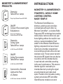
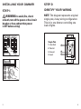
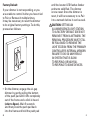
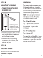
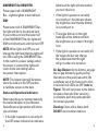
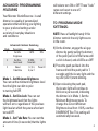
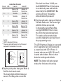
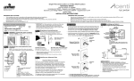
IN-WALL DIMMER
ML IWD 600S
DESIGNER SERIES
I N S TALL ATION
& U S ER GUIDE
MONSTER® ILLUMINESSENCE™
PRODUCTS:
Dimmable
Table & Floor Lamps
Plug In Light Station Dimmer ML LD 300
ON/OFF
Compact Fluorescent Lights
& Appliances
Plug In Light & Appliance
Station Dimmer ML LAS 1000
Dimmable
Ceiling Lights
Table & Floor Lamps
In Wall Dimmer ML IWD 600S
ON/OFF
Ceiling Fluorescents
Table & Floor Lamps
In Wall Switch ML IWS 1000S
Controls All or Selected
Lights at the Push
of a Button
In Wall Scene Controller ML IWC 600
INTRODUCTION
MONSTER® ILLUMINESSENCE™:
POWERFUL WHOLE HOME
LIGHTING CONTROL
MADE SIMPLE
The Monster IlluminEssence™
dimmers, switches and controllers
communicate with each other via
Monster ControlNet™, a wireless Radio
Frequency (RF) technology that provides
whole-house remote control over your
home lighting without the need for new
wiring or custom installation. Each
station in the Monster IlluminEssence
lighting component line has on board
memory to remember programmed
scene settings and also acts as its own
wireless router. These routers transmit
the wireless RF signals from one device
to another until the intended device
is reached and controlled according
to the user’s preferences. This ensures
that the signal is received by its
intended device by routing the signal
around obstacles and radio dead
spots. Thanks to this innovative routing
system and wireless RF ControlNet,
IlluminEssence modules can work
1
through floors, walls, ceilings and
cabinets. IlluminEssence scene-capable
dimmer modules are compatible with any
Z-Wave™ enabled network, regardless
of the manufacturer, and can also
be used with other devices displaying
the Z-Wave logo.
• Dimmer may feel warm to the touch
during normal operation.
• Recommended minimum wall box
depth is 2-1/2".
• Disconnect power at circuit breaker
or fuse when servicing, installing
or removing fixture.
• Do not exceed the 600W rating
as shown on the safety label.
• Use this device only with copper
or copper clad wire. With aluminum
wire use only devices marked CO/ALR
or CU/AL.
• Dimmer may not operate with dioded
lamps (Sylvania Designer 16™
or Philips PAR-16™).
• To be installed and/or used in
accordance with appropriate
electrical codes and regulations.
WARNINGS AND CAUTIONS:
• Total minimum load must exceed 40W.
Monster Recommends that you remember
to exercise good common sense when using
any timer features in a remote-controllable
system, especially when scheduling
unattended devices. There can be some
unexpected consequences if not used with
care. For example, an empty coffee pot can
be remotely turned on. If that should happen,
your coffee pot could be damaged from
overheating. If an electric heater is turned
on by remote control while clothing
2
is draped over it, a fire could result.
DO NOT USE the Illuminessense In Wall
or Plug In Light Stations for the control
of high power heating appliances such
as portable heaters. This device will not
control lighting that is used with electronic
low-voltage and high frequency power
supply transformers, nor high pressure
discharge lamps (HID lighting).
This includes mercury-vapor, sodium
vapor and metal halide lamps.
3
• If you are unsure about any part
of these instructions, consult
a qualified electrician.
• This device is intended for indoor
use only.
TOOLS NEEDED TO INSTALL
YOUR ILLUMINESSENCE™
IN-WALL DIMMER:
• Slotted/Phillips Screwdriver
• Electrical Tape
• Pliers
• Pencil
• Cutters (If Necessary)
• Ruler
PREPARE FOR INSTALLATION
• Make sure that there is plenty of task
lighting (or natural sunlight) to work
in the room you would like to install
IlluminEssence™ lighting so that
you don’t find yourself performing
installation with inadequate light.
• Please confirm that electrical load
4 does not exceed 600W. Check to see
if existing in wall switch/dimmer
already in place is controlling less
than 600W before proceeding
with installation.
• It is important to ensure that all
circuit breakers are turned OFF
prior to installation! To do this,
follow these steps:
1) Start by turning ON the in-wall
dimmers and/or switches that you
intend to replace with IlluminEssence
in-wall light stations.
2) Find your home circuit breaker panel
and turn off the appropriate labeled
breakers for the room that you plan
to be installing IlluminEssence
in-wall light stations.
3) Return to the room and CONFIRM
that the electricity is turned off.
Remove the existing decorative wall
plate with a screwdriver and proceed
to remote the in wall dimmer
or dimmer.
4) Note the current color of the
electrical leads on the existing
dimmer: GREEN = GROUND, BLACK =
HOT, and in many installations,
5
BLACK or WHITE may be
the color neutral.
5) Remove the caps or screws on your
existing dimmer to release the wires.
FEATURES
• Remote Controlled Scene Capable—
reacts to programmable
lighting commands
• No new wiring, simple installation
• LED indicator provides visual
on-off status
• 2-way communication shows status
confirmation at the controller such as
the IWC 600 (some remotes/controllers
may not have this feature enabled)
USING YOUR DIMMER
IN MULTI-LIGHT OR
MULTI-DEVICE APPLICATIONS
If you’ll be installing your Monster
IlluminEssence™ dimmer without any
other additional IlluminEssence light
stations, skip this section and proceed
to the next section, “Installing Your
Dimmer.” If you’ll be installing Dimmer
in a multi-device application where
there will be multiple IlluminEssence
dimmers in a single installation location,
a reduction of the dimmer’s capacity
is required. Be sure to check each light
fixture to make sure it does not exceed
the indicated wattage capacity by itself
or as a group of light fixtures.
• Wireless Monster ControlNet ™
system intelligently routes commands
throughout the home up to 100ft*
between Light Station, Monster
Central Controller or other Z-Wave
enabled remote
• Compatible with other Monster
ControlNet™ and Z-Wave™ enabled
controllers/remotes
*Actual range may vary
6
7
INSTALLING YOUR DIMMER
STEP 2:
STEP 1:
IDENTIFY YOUR WIRING:
WARNING: to avoid, fire, shock
or death, turn off the power at the circuit
breaker or fuse and test that power
is OFF before wiring!
NOTE: This diagram represents a typical
single-pole, 2-way wiring configuration.
This is for one dimmer controlling one
load of lights.
8
���
��
���
��
���
��
���
��
���
��
���
��
���
��
���
��
���
��
���
��
���
��
���
��
Single-Pole
1. Line (Hot)
2. Neutral
3. Ground
4. Load
�
�
�
�
9
STEP 3:
STEP 4:
PREPARING
AND CONNECTING WIRES:
SINGLE POLE WIRING:
This dimmer can be wired using side wire
terminal screws or through backwire
openings. Choose the appropriate wire
stripping specifications accordingly.
Cut (if necessary)
Strip Gage
(measure
bare wire
here)
Side Wire Connection
Side wire terminals
accept #14 AWG solid
copper wire only.
5/8"
(1.6 cm)
Back Wire (either
hole may be used)
Back wire openings
use #14-12 AWG solid
copper wire only.
• Make sure that the ends of the wires
from the wall box are straight
(cut if necessary).
Terminal Screw
marked Black (BK)
Terminal Screw
marked Yellow/
Red (YL/RD)
��
�
�
�
�
����� �
�
Terminal Screw
marked Red (RD)
Terminal Label:
Use Terminal for 3-Way or More
Applications Only. For Single-Pole
Applications, Do Not Remove This Label.
Note: For standard single-pole
installations, leave the terminal
label untouched.
• “Single Pole” refers to the application
of one dimmer or switch to control
one or a set of lights on one
electrical load.
• Three-way travel wire may be used
with the matching Illuminessence
3-way auxiliary ON/OFF switch
(Not included).
• Remove insulation from each wire
in the wall box as shown.
10
11
WIRING DIMMER:
STEP 5:
Connect wires per WIRING DIAGRAM
as follows:
TESTING YOUR DIMMER
BEFORE MOUNTING
������
��
��
�����������
������������
�����
�����
����
�����
��������������������������
����������������������������
��������������������������
�������������������������
����
��������
����
���������������
• The Green or bare copper wire in wall
box goes to the Green terminal screw.
• Line Hot wall box wire goes
to the terminal screw marked “BK”.
• Load wall box wire goes to the terminal
screw marked “RD”.
• Dimmer terminal screw marked
“YL/RD” should have Red insulation
label affixed.
NOTE: If insulating label is not affixed
to terminal screw marked “YL/RD”,
use electrical tape to cover it.
12
• Position all wires to provide room
in outlet wall box for device.
• Ensure that the word “TOP” is facing
up on device strap.
• Partially screw in mounting screws
in wall box mounting holes.
NOTE: Bend the wires slightly as shown
in diagram in order to relieve stress
when mounting device.
13
STEP 6:
PAIRING YOUR
ILLUMINESSENCE IN-WALL
DIMMER INTO THE NETWORK
Locator Light
1) Follow the instructions on your
Monster Controller/Programmer
to Pair a Monster IlluminEssence™
or other Z-Wave-enabled lighting
station into the lighting network.
When it’s ready to Pair a new device,
proceed to Step 2.
• Restore power at the circuit breaker
or fuse.
• Press pad until locator light is OFF.
Lights should turn ON.
• If lights do not turn ON, press the upper
half of DIM/ BRIGHT bar until
the lights brighten.
• If lights still do not turn ON, refer
to the TROUBLESHOOTING section.
AVL 300
Programmer/
Controller
NOTE: Remote must be
in close proximity to dimmer
when pairing in the network
14
15
2) While standing close to the dimmer
(approximately 2-5 ft.) with the
controller in hand, press the center
button on the dimmer to Pair
it in the network.
NOTE: Only one device may be Paired
at a time. DO NOT put multiple devices
into the Pairing mode at any time.
3) While the Controller/Programmer
is in the Pairing mode and the Locator
LED is ON on the dimmer, press
the push pad to turn on the dimmer.
The Programmer/Controller will verify
the Pairing and the Locator LED
will turn OFF on the dimmer.
4) If the dimmer is flashing Amber while
in the Pairing mode, the Programmer/
Controller is still trying to communicate
with the dimmer. Wait until the device
Monster IlluminEssence™ lighting
modules use a wireless technology called
Monster ControlNet™ that brings your
home lighting fixtures into a simplified
network. In order for the network to
properly recognize each lighting source,
each light must be Paired or Included
16
stops flashing, then press the push
the pad.
NOTE: If the Locator LED on the dimmer
turns solid Red while Pairing, there
has been a communication error.
Refer to your ControlNet™ or Z-Wave™
controller manual.
5) The dimmer is now installed
in the network.
NOTE: You only Pair a lighting station
into the network once. If the dimmer
has already been successfully Paired
in the network and you try to Pair it
again without first Removing it from
the network, the dimmer will not pair
successfully.
to the network. This process is
necessary for each lighting device you
want to add to the network, and you
only need to do it once. When you want
to Remove a light from your lighting
network, you Remove or Exclude that
light, so that the network doesn’t need
to recognize it anymore.
17
STEP 7:
REMOVING/EXCLUDING AN
ILLUMINESSENCE IN-WALL
DIMMER FROM THE NETWORK
1) Follow the instructions on your
Monster Controller/Programmer
to Remove a Monster IlluminEssence™
or other Z-Wave-enabled lighting
station from the lighting network.
When it’s ready to Remove the device
that you want Removed, proceed
to Step 2.
LED is ON on the dimmer, press
the push pad to turn on the dimmer.
The Programmer/Controller will verify
Removal and the locator LED will turn
OFF. If the dimmer is flashing Amber
while in the Removal mode,
the Programmer/Controller is still trying
to communicate with the dimmer.
Wait until the device stops flashing,
then press the push pad.
2) While standing close to the dimmer
(approximately 2-5 ft.) with
the controller in hand, press
the center button to Remove
device from the network.
3) While the Programmer/Controller
is in the Removal mode and the locator
When you want to Remove a light from
your Monster ControlNet™ system
or any wireless Z-Wave network, it is
very important to accurately Remove it
from the network This ensures that all
information has been Removed from
18
your Primary Programmer/Controller’s
information and that unwanted lights
are not counted on to be part of the
network. Removing/Excluding a light
station also clears the light itself
making it ready to be Paired into
a new network or re-added.
19
Factory Default:
If your dimmer is not responding, or you
are unable to control it after you have tried
to Pair or Remove it multiple times,
it may be necessary to reset the dimmer
to its original factory settings. To do this,
proceed as follows:
until the locator LED flashes Amber
and turns solid Red. The dimmer
is now reset. Once the dimmer is
reset, it will be necessary to re-Pair
it to a network before it can be used.
CAUTION: SETTING AN
ILLUMINESSENCE LIGHT STATION
TO A FACTORY DEFAULT DOES NOT
REMOVE IT FROM A NETWORK. THE
REMOVAL PROCEDURE MUST STILL
BE FOLLOWED TO REMOVE THE
LIGHT STATION FROM THE PRIMARY
CONTROLLER’S INTERNAL MEMORY.
FAILURE TO DO SO MAY RESULT
IN SYSTEM THAT IS SLOW
TO RESPOND, OR MAY FAIL
TO RESPOND TO SOME DEVICES.
• On the dimmer, engage the air-gap
dimmer by gently pulling the bottom
of the push pad until it lifts completely
out of the frame and a click is heard.
(refer to figure). Wait 5 seconds
and then press the push pad back
into the frame and hold the push pad
20
21
STEP 8:
OPERATION
MOUNTING THE DIMMER
For complete details on operating your
lighting within a Monster ControlNet™
or other Z-Wave-enabled network, refer
to the instruction guide of your Monster
Central or other lighting controller.
• TURN OFF POWER AT THE CIRCUIT
BREAKER OR FUSE!
NOTE: The locator light will illuminate
when the load is in the OFF position
to facilitate access in the dark.
Turn ON from OFF position:
Installation may now be
completed by tightening
mounting screws into wall
box. Attach wallplate.
• Install the wall plate by fitting the inner
plate over the housing of the dimmer,
which will snap into place.
• Install the outer plate by affixing
it to the inner plate. The outer plate
will snap into place.
Tap – Lights turn ON to preset level.
Press and Hold – Lights turn ON
to full bright.
Turn OFF from ON position:
Tap – Lights turn OFF.
Press and Hold until lights DIM to lowest
level and LED in LED Brightness Display
starts to blink – Lights remain ON for 10
seconds and then turn OFF.
STEP 9:
RESTORE POWER
Restore power at circuit breaker or fuse.
Installation is complete.
22
23
DIM/BRIGHT Bar BRIGHTEN:
Press upper half of DIM/BRIGHT
Bar – Lights brighten to desired level.
DIM:
Press lower half of DIM/BRIGHT Bar –
the light will dim to the desired level.
If you continue to hold the lower half
of the DIM/BRIGHT Bar, the lights will
DIM to minimum level and then turn OFF.
NOTE: When lights are OFF you can
change the light level that the lights will
turn ON to using the DIM/BRIGHT Bar.
In the event of a power outage, when
the power is restored the lights will
return to the last setting before
the power interruption.
NOTE: The locator light will illuminate
when the load is in the OFF position
to facilitate access in the dark.
Status and Operational Indicators:
When operating your system manually,
the status indicator of your Monster
IlluminEssence light station will inform
you as follows:
what level the light will return when
you turn it back on.
• If the light in question is currently
is currently on, the indicator shows
the brightness level that the dimmer
is currently set to.
• The toggle dim bar on the right
hand side of the dimmer will dim
the brightness up or down if the light
is on.
• If the light in question is currently off,
the toggle dim bar can change
the preset level that the light
will go to when it is turned on.
Air-Gap Dimmer: On the dimmer, engage
the air-gap dimmer by gently pulling
the bottom of the push pad until it lifts
completely out of the frame and a click
is heard and all LED’s are OFF (refer to
Figure). This will cut power to the fixture
to replace the bulb. After servicing
is complete, push the push pad back
for normal operation.
Cleaning: Clean with a damp cloth.
DO NOT use chemical cleaners.
• If the light in question is currently off,
the LED status indicator bar indicates
24
25
ADVANCED PROGRAMMING
FEATURES
Your Monster IlluminEssence™ in-wall
dimmer is capable of personalized
operations that will bring your lighting
to your preferred settings under
a variety of everyday situations
and conditions:
Advanced Features Summary
Mode
1
Description
Set Min.
Brightness
Range
1-50%
Default
25%
2
Set DimLock Level
0-100%,
0=no lock
0
3
Select
Fade Rate
1, 2, 3, 4,
5, 6 or 7
Preset #1
Mode 1 – Set Minimum Brightness:
You can set the minimum brightness level
that the lights can dim to prior
to turning full OFF.
Mode 2 – Set Dim-Lock: You can set
the brightness level that the lights
will turn on to regardless of the previous
light level at which they were when last
turned OFF.
Mode 3 – Set Fade Rate: You can set the
amount of time (in seconds) that the lights
26
will take to turn ON or OFF. These “fade”
rates can be set to one of 7
different settings.
TO PROGRAM MODE
SETTINGS:
NOTE: Have a flashlight handy if this
dimmer controls the only light source
in the room.
1) On the dimmer, engage the air-gap
dimmer by gently pulling the bottom
of the push pad out of the frame until
a click is heard, and all LEDs are OFF.
2) Press the push pad back into the
frame and hold the push pad for 7
seconds until the locator light and the
top LED (LED 1) starts blinking.
3) Upon releasing the push pad,
the locator light will continue to
blink once per second, indicating
the dimmer is in Mode 1, Set the
Minimum Brightness mode. To
change the current Minimum
Brightness level from 1-50%, use the
DIM/BRIGHT Bar. This setting will
automatically be saved.
27
Preset
1*
*
**
***
Fade Rate Presets
LED**
Fade On
Fade Off
1
Approx. 1.5s
Approx. 3s
from full off
from full on
2***
2
No Fade
No Fade
3
3
No Fade
Approx. 3s
from full on
4
4
Approx. 0.5s
from full off
Approx. 3s
from full on
5
5
Approx. 0.5s
from full off
Approx. 1.5s
from full on
6
6
Approx. 1.5s
from full off
Approx. 5s
from full on
7
7
Approx. 1.5s
from full off
Approx. 10s
from full on
default
LED #1 is located at the top
The press and hold feature for the 10 second
delayed off is disabled in this mode.
�
�
�
�
�
�
�
���
����������
�������
Dim-Lock level from 1-100%, use
the DIM/BRIGHT Bar. If this feature
is not desired, press and hold the
lower half of the DIM/BRIGHT Bar
until no LED is lit. This setting
will automatically be saved.
5) Tap the push pad to change to Mode 3,
Set Fade Rate mode. The locator light
will blink 3 times per second.
To change the current Fade Rate,
use the DIM/BRIGHT Bar to move
the LED to the desired preset level.
This setting will automatically be
saved by tapping the push pad to exit
the programming mode.
The LED Brightness Display is separated
into 7 segments. Each LED represents
a preset level with LED 1 (Preset 1)
located at the top and LED 7 (Preset 7)
located at the bottom. Refer to chart
below for settings and defaults.
NOTE: The dimmer will exit program
mode after 3 minutes of inactivity.
4) Tap the push pad to change to Mode 2,
Set Dim-Lock Level mode.
The locator light will blink twice per
second. To change the current Set
28
29
TROUBLESHOOTING
LIGHTS ARE FLICKERING.
• Lamp has a bad connection.
• The wires are not secured firmly
under terminal screws of dimmer
and/or remote.
• The lamp may not be designed
for true dimmable control such
as non-dimmable fluorescent lighting.
LIGHT DOES NOT TURN ON
AND LOCATOR LED DOES
NOT TURN ON
• Circuit breaker or fuse has tripped.
• Lamp is burned out.
• Lamp Neutral connection is not wired.
• Confirm that the device is being
supplied from a 120V, 60Hz AC
source ONLY.
• Confirm that unit is programmed
properly. Repeat “TO INSTALL” section
to verify that it has been Paired in the
ControlNet™ or other Z-Wave network.
30
INTERMITTENT DIMMER
OPERATION
• Minimum load is under 40W.
• Confirm that the light(s) being
controlled do not exceed the rated
dimmer capacity
LIGHT CANNOT BE PAIRED/
INCLUDED INTO MONSTER
CONTROLNET CONTROLS
• Use controller to delete or Remove
the light station
CONTROLLER DOES NOT
OPERATE LIGHTS
• Ensure that total wire length does
not exceed 300 ft. from your IWD 600S
and your light fixture.
LIGHT DOES NOT TURN ON
AND LOCATOR LED DOES
NOT TURN ON
• The circuit breaker or fuse may
have tripped.
• The lamp is burned out.
• The lamp Neutral connection
is not wired.
31
FCC COMPLIANCE STATEMENT
This equipment has been tested and found
to comply with the limits for a Class B Digital
Device, pursuant to Part 15 of the FCC
Rules. These limits are designed to provide
reasonable protection against harmful
interference in a residential installation.
This equipment generates, uses, and can
radiate radio frequency energy and, if not
installed and used in accordance with the
instructions, may cause harmful interference
to radio communications. However, there
is no guarantee that interference will not
occur in a particular installation. If this
equipment does cause harmful interference
to radio or television reception, which can
be determined by turning the equipment OFF
and ON, the user is encouraged to try to
correct the interference by one or more
of the following measures:
• Reorient or relocate
the receiving Antenna.
• Increase the separation between
the equipment and the receiver.
• Connect the equipment into an outlet on
a circuit different from that to which the
receiver is connected.
• Consult the dealer or an experienced
radio/tv technician for help.
32
LIMITED WARRANTY
FOR CONSUMERS
Monster, LLC, 7251 West Lake Mead Blvd.,
Suite 342, Las Vegas, NV 89128, USA,
(415) 840-2000 (“Monster”) extends You
this Limited Warranty. Statutory or common
law may provide You with additional rights
or remedies, which shall not be affected
by this Limited Warranty.
DEFINITIONS
“Adequate Use” means use of the Product
(i) within a home or dwelling, (ii) for private
(as opposed to commercial) purposes,
(iii) in conformance with all applicable local,
state or federal law, code or regulations
(including without limitation building
and/or electrical codes), (iv) in accordance
with manufacturer recommendations
and/or instructions in the materials
and documentation that accompany
the Product, and (v) with proper
electrical grounding.
“Authorized Dealer” means any distributor,
reseller or retailer that (i) was duly
authorized to do business in the jurisdiction
where it sold the Product to You, (ii) was
permitted to sell You the Product under the
laws of the jurisdiction where You bought
the Product, and (iii) sold You the Product
new and in its original packaging.
33
“Formal Warranty Claim” means a claim
made in accordance with the section
“Formal Warranty Claims” herein.
“Product” means a Product (i) that is listed
in the Specifications Table below, (ii) that
You bought from an Authorized Dealer new
and in its original packaging, and (iii) whose
serial number, if any, has not been removed,
altered, or defaced.
“Product Defect” means an inadequacy
of the Product that existed at the time when
You received the Product from an Authorized
Dealer and that causes a failure of the
Product to perform in accordance with
Monster’s documentation accompanying
the Product, unless such failure has been
caused completely or partly by (a) any use
other than Adequate Use, (b) transportation,
neglect, misuse or abuse by anyone other than
Monster’s employees; (c) alteration, tampering
or modification of the product by anyone other
than a Monster employee; (d) accident (other
than a malfunction that would otherwise
qualify as a Product Defect); (e) maintenance
or service of the Product by anyone other
than a Monster employee; (f) exposure of the
Product to heat, bright light, sun, liquids, sand
or other contaminants; or (g) acts outside the
control of Monster, including without limitation
acts of God, fire, storms, earthquake or flood.
34
“Warranty Period” means the time period
during which Monster must have received
Your Formal Warranty Claim. The different
Warranty Periods related to Product Defects
are defined in the Specifications Table
below. The Warranty Period commences on
the date when You purchased or received
(whichever occurs later) the Product from
an Authorized Dealer as evidenced by the
Authorized Dealer’s invoice, sales receipt
or packing slip. If You do not have written
proof of the date of purchase or receipt,
then the Warranty Period commences three
(3) months after the date when the Product
left Monster’s or its factory as evidenced
by Monster’s records. The Warranty
Period ends after the time defined in the
Specifications Table has expired or after You
have transferred ownership of the Product,
whichever occurs earlier. Also, You must call
Monster and obtain a Return Authorization
Number (as described under “How to Make
a Claim”) within two (2) months after You
discover a Product Defect (or should have
discovered it, if such Product Defect
was obvious).
“You” means the first individual person
that purchased the Product in its original
packaging from an Authorized Dealer. This
Limited Warranty does not apply to persons
or entities that bought the Product (i) in used
or unpackaged form, (ii) for resale, lease or
35
other commercial use, or (iii) from someone
other than an Authorized Dealer.
SCOPE OF THIS
LIMITED WARRANTY
PRODUCTS. If a Product contained a Product
Defect when You bought it from an Authorized
Dealer and Monster receives a Formal
Warranty Claim from You within two (2) months
after You discover such Product Defect (or
should have discovered it, if such Product
Defect was obvious) and before the end of
the Warranty Period for Product Defects
applicable to the affected Product,
then Monster will provide You with one
of the following remedies: Monster will
(1) repair or, at Monster’s sole discretion,
replace the Product, or (2) refund
to You the purchase price You paid
to the Authorized Dealer for the affected
Product if repair or replacement is not
commercially practicable or cannot be timely
made. NOTE: MONSTER DOES NOT ASSUME
ANY LIABILITY FOR ANY INCIDENTAL,
CONSEQUENTIAL OR INDIRECT DAMAGES
UNDER THIS LIMITED WARRANTY.
GENERAL PROVISIONS
Warranty (“Disputes”) shall be governed
by the laws of the State of California, USA,
excluding conflicts of law principles and
excluding the Convention for the International Sale of Goods. The courts located
in the State of California, USA shall have
exclusive jurisdiction over any Disputes.
OTHER RIGHTS. THIS LIMITED WARRANTY
GIVES YOU SPECIFIC LEGAL RIGHTS,
AND YOU MAY ALSO HAVE OTHER RIGHTS,
WHICH VARY FROM STATE TO STATE
AND JURISDICTION TO JURISDICTION,
AND WHICH SHALL NOT BE AFFECTED
BY THIS LIMITED WARRANTY.
THIS WARRANTY EXTENDS ONLY
TO YOU AND CANNOT BE TRANSFERRED
OR ASSIGNED. If any provision of this
Limited Warranty is unlawful, void or
unenforceable, that provision shall be
deemed severable and shall not affect
any remaining provisions. In case of any
inconsistency between the English and
other versions of this Limited Warranty,
the English version shall prevail.
REGISTRATION. Please register Your Product
at MonsterCentral.com. Failure to register
will not diminish Your warranty rights.
CHOICE OF LAW/JURISDICTION.
This Limited Warranty and any disputes arising
out of or in connection with this Limited
36
37
SPECIFICATIONS TABLE
Product Model
Warranty Period
for Product
ML IWD 600S
Three (3) Years
FORMAL WARRANTY CLAIM
HOW TO MAKE A CLAIM. In the event damage
has occurred to Products, You must follow
these instructions: (1) Call Monster within
two (2) months after You discover a Product
Defect (or should have discovered it, if
such Product Defect was obvious); (2) Give
a detailed explanation of how the damage
occurred; (3) Obtain a Return Authorization
Number; (4) Upon receipt of a claim form
(which may be sent to You after You filed Your
Formal Warranty Claim), fill out the claim form
entirely; (5) Return the Products, shipping
prepaid by You (to be refunded if You are
entitled to a remedy under the Scope of this
Limited Warranty), to Monster for verification
of damage, along with a copy of Your original
sales receipts and proof of purchase (UPC
label or packing slip) for such Products, the
completed claim form, and printed Return
Authorization Number on the outside of the
return package (the claim form will include
instructions for return).
38
TELEPHONE NUMBERS. United States, Asia
Pacific and Latin America: 1 877 800-8989
or 415-840-2000, Canada 1-866-348-4171,
Czech Republic 800-14247, UK 0800 0569520,
Germany 0800 1819388, France 0800 918201,
Netherlands 0800 0228919, Belgium 0800
79201, Norway 800 10906, Denmark 8088
2128, Sweden 020 792650, Finland 800 112768.
FURTHER PROCEEDINGS. Monster will
determine whether a Product Defect existed.
Monster may, at its discretion, direct You
to obtain a repair estimate at a service
center. If a repair estimate is required, You
will be instructed on how to properly submit
the estimate and the resulting invoice to
Monster for payment. Any fees for repairs
may be negotiated by Monster.
TIMING. If You bring a Formal Warranty
Claim and fully comply with all terms and
conditions of this Limited Warranty, Monster
will use its best efforts to provide You with a
remedy within thirty (30) days after receipt of
Your Formal Warranty Claim (if You reside in
the United States – forty-five (45) days if You
reside elsewhere), unless obstacles outside
Monster’s control delay the process.
Ver.121703 – US/EU
©2003 Monster, LLC
39
MonsterCentral.com
© 2006 Monster, LLC
7251 West Lake Mead Blvd.
Las Vegas, NV 89128, USA
1-877-800-8989
Monster Central products are designed
in the USA and manufactured for Monster
to its quality specifications.
Manufactured in Mexico.
Monster, Monster Central, the Monster
Central logo and the product design,
Omnilink, Monster System Tracking Memory,
IlluminEssence, ControlNet, are registered
or unregistered trademarks of Monster Cable
Products, Inc. or its subsidiaries
in the US and other countries.
rm 162839