1
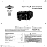
Operating & Maintenance
Instructions
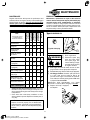
Model Series
Covered in
this Manual,
Includes
Gasoline,
Natural Gas
and Liquid
Propane Gas
Engines
290000
300000
350000
380000
Model
Type
Code
Note: General Model Series numbers noted above include many specific numbers
like the ones on your engine. To get replacement parts or technical assistance in
the future, write your engine Model, Type, Code and date of purchase here.
TABLE OF CONTENTS
Safety . . . . . . . . . . . . . . . . . . . . . . . . . . . . . . . . . . . 3
Engine Information . . . . . . . . . . . . . . . . . . . . . . . . 6
Oil . . . . . . . . . . . . . . . . . . . . . . . . . . . . . . . . . . . . . . . 7
Fuel . . . . . . . . . . . . . . . . . . . . . . . . . . . . . . . . . . . . . 8
Starting and Stopping . . . . . . . . . . . . . . . . . . . . . . 9
Maintenance . . . . . . . . . . . . . . . . . . . . . . . . . . . . 11
Adjustments . . . . . . . . . . . . . . . . . . . . . . . . . . . . . 14
Parts and Service & Storage . . . . . . . . . . . . . . . 16
Warranty Information . . . . . . . . . . . . . . . . . . . . . 17
PRINTED IN U.S.A.
Document: - page 1 (Black)
Screen angle and frequency: 45.0000, 150.0000
Month Day Year
WARNING
Briggs & Stratton does not approve or authorize the use of
these engines on 3-wheel All Terrain Vehicles (ATVs), motor
bikes, aircraft products or vehicles intended for use in
competitive events. Use of these engines in such applications
could result in property damage, serious injury (including
paralysis), or even death.
Need assistance? Visit our website for detailed information
regarding Briggs & Stratton engines,
www.briggsandstratton.com
In the USA and Canada, a 24 hour hot line,
1-800-233-3723,
has a menu of pre-recorded messages offering engine
maintenance information.
Copyright 2003 by Briggs & Stratton Corporation
FORM NO. 275368-5/03
The Power That Works For You.
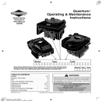
Look For Relevant Emissions Durability Period and
Air Index Information On Your Engine Emissions Label
Engines that are certified to meet the California Air Resources Board (CARB) Tier 2 Emission Standards must display information regarding the Emissions Durability Period and the Air Index. Briggs & Stratton makes this information available to the consumer on our emission
labels.
The Emissions Durability Period describes the number of hours of actual running time for which the engine is certified to be emissions
compliant, assuming proper maintenance in accordance with the Operating & Maintenance Instructions. The following categories are
used:
Moderate:Engine is certified to be emission compliant for 125 hours of actual engine running time.
Intermediate:Engine is certified to be emission compliant for 250 hours of actual engine running time.
Extended:Engine is certified to be emission compliant for 500 hours of actual engine running time.
For example, a typical walk-behind lawn mower is used 20 to 25 hours per year. Therefore, the Emissions Durability Period of an engine with an intermediate rating would equate to 10 to 12 years.
The Air Index is a calculated number describing the relative level of emissions for a specific engine family. The lower the Air Index, the
cleaner the engine. This information is displayed in graphical form on the emissions label.
After July 1, 2000, Look For Emissions Compliance Period
On Engine Emissions Compliance Label
After July 1, 2000 certain Briggs & Stratton engines will be certified to meet the United States Environmental Protection Agency (USEPA)
Phase 2 emission standards. For Phase 2 certified engines, the Emissions Compliance Period referred to on the Emissions Compliance
label indicates the number of operating hours for which the engine has been shown to meet Federal emission requirements. For engines
less than 225 cc displacement, Category C = 125 hours, B = 250 hours and A = 500 hours. For engines of 225 cc or more, Category
C = 250 hours, B = 500 hours and A = 1000 hours.
The displacement of Model Series 290000 and 300000 engines is 480 cc, 350000 engines is 570 cc, and 380000 engines is 627 cc.
2
Document: - page 2 (Black)
Screen angle and frequency: 45.0000, 150.0000
275368
THE OPERATING & MAINTENANCE
INSTRUCTIONS CONTAIN SAFETY
INFORMATION TO
BEFORE OPERATING ENGINE
• Read entire Operating & Maintenance Instructions
AND the instructions for the equipment this engine
powers.*
• Failure to follow instructions could result in serious
injury or death.
(
• Make you aware of hazards associated with engines
• Inform you of the risk of injury associated with those
hazards, and
• Tell you how to avoid or reduce the risk of injury.
)
The safety alert symbol
is used to identify safety
information about hazards that can result in personal injury.
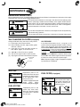
HAZARD SYMBOLS AND MEANINGS
A signal word (DANGER, WARNING, or CAUTION) is
used with the alert symbol to indicate the likelihood and the
potential severity of injury. In addition, a hazard symbol
may be used to represent the type of hazard.
Fire
Explosion
Moving Parts
DANGER indicates a hazard which, if not
avoided, will result in death or serious injury.
Toxic Fumes
Shock Hot Surface
Kickback
WARNING indicates a hazard which, if not
avoided, could result in death or serious injury.
Wear Eye Protection
Frostbite
CAUTION indicates a hazard which, if not
avoided, might result in minor or moderate
injury.
THE INTERNATIONAL SYMBOLS USED
ON THE ENGINE OR
IN THIS MANUAL INCLUDE:
CAUTION, when used without the alert symbol,
indicates a situation that could result in damage
to the engine.
Safety Alert
Read Operating &
Maintenance Instructions
WARNING
The engine exhaust from this product
contains chemicals known to the State of
California to cause cancer, birth defects, or
other reproductive harm.
*
On Off
Oil
Stop
Fuel Shutoff
Choke
Fuel
Briggs & Stratton does not necessarily know what equipment this engine will power. For that reason, you should carefully read
and understand the operating instructions for the equipment on which your engine is placed.
3
Document: - page 3 (Black)
Screen angle and frequency: 45.0000, 150.0000
SAFETY
WARNING
WARNING
0
-" !& !.
• ' + • ' + • ' + • * • # • • • !" ! • " • # $ % #&&/#.
• 1)0 +0 2 • " • ' + • ' + $
• 2*%* • - '
+ - • " $ • (
!
!# • & • ' • ( • ( !" )*+!%,+ -. "$# %$& !" • ' $ • ' #!$"# %$&
• *&)/ • # ' %( $#"& )$* ! WARNING
!"# "# %$& + "# ,-(#
3 • . ! 1) $
• (
4
$ • % 4
Document: - page 4 (Black)
Screen angle and frequency: 45.0000, 150.0000
SAFETY
WARNING
WARNING
. . % * *
. #
• - • % • (
$ # $
6.
888 # ) %
#7 • ( 1) • ' 5 • . + 0
) $ !
WARNING
WARNING
% 67 % 2 • $ • " • 4
• ' • 3 • % $! • ' $ WARNING
, WARNING
, *
/"# $#"#& (0!&! "# #$#!
• '
• '
6 7
2 • . • ' ! "# !$#+
• ,
• ' 5
Document: - page 5 (Black)
Screen angle and frequency: 45.0000, 150.0000
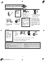
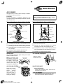
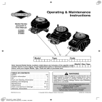
ENGINE INFORMATION
Equipped with optional fuel tank.
12
15
4
1
2
11
10
14
13
3
4
5
9
16
6
8
7
17
1.
2.
3.
4.
5.
Oil fill cap
Dipstick
Fuel pump (if equipped)
Spark plug
Emission label and Engine
Model
Type
Code
xxxxxx
xxxx xx
xxxxxxxx
6. 12V electric starter (if equipped)
7. Oil drain plug
8. Blower housing
9.
10.
11.
12.
13.
14.
15.
16.
17.
GENERAL INFORMATION
Rope handle
Carburetor or LPG/NG Fuel mixer
Stop switch (if equipped)
Air cleaner (without fuel tank)
Fuel shut-off valve (if equipped)
Air cleaner (with fuel tank)
Fuel fill/fuel tank (if equipped)
Exhaust manifold
Oil filter (if equipped)
in similar applications, and will therefore not necessarily match the
values derived using the foregoing codes.
This is a twin cylinder, overhead valve (OHV), air-cooled engine.
It is a low emissions engine.
In the state of California, Model Series 290000, 300000, 350000
and 380000 engines are certified by the California Air Resources
Board to meet emissions standards for 250 hours. Such
certification does not grant the purchaser, owner or operator of this
engine any additional warranties with respect to the performance
or operational life of this engine. This engine is warranted solely
according to the product and emissions warranties stated
elsewhere in this manual.
TUNE-UP SPECIFICATIONS
Armature air gap . . . . . . . . . 0.008 – 0.012 in. (0.20 – 0.30 mm)
Spark plug gap . . . . . . . . . . . . . . . . . . . . . . . . 0.030 in. (0.76 mm)
Valve clearance with valve springs installed and piston 1/4 in.
(6 mm) past top dead center (check when engine is cold). See
Repair Manual P/N 272144.
Intake . . . . . . . . . . . . . . . . . . . 0.004 – 0.006 in. (0.10 – 0.15 mm)
Exhaust . . . . . . . . . . . . . . . . . 0.004 – 0.006 in. (0.10 – 0.15 mm)
TECHNICAL INFORMATION
MODEL SERIES 290000 and 300000
POWER RATINGS: The power ratings for an individual engine
model are initially developed by starting with SAE (Society of
Automotive Engineers) code J1940 (Small Engine Power &
Torque Rating Procedure) (Revision 2002-05). Given both the
wide array of products on which our engines are placed, and the
variety of environmental issues applicable to operating the
equipment, it may be that the engine you have purchased will not
develop the rated horsepower when used in a piece of power
equipment (actual “on-site” power). This difference is due to a
variety of factors including, but not limited to, the following:
differences in altitude, temperature, barometric pressure,
humidity, fuel, engine lubrication, maximum governed engine
speed, individual engine to engine variability, design of the
particular piece of power equipment, the manner in which the
engine is operated, engine run-in to reduce friction and clean out
of combustion chambers, adjustments to the valves and
carburetor, and other factors. The power ratings may also be
adjusted based on comparisons to other similar engines utilized
Bore . . . . . . . . . . . . . . . . . . . . . . . . . . . . . . . . . . . . 2.68 in. (68 mm)
Stroke . . . . . . . . . . . . . . . . . . . . . . . . . . . . . . . . . . 2.60 in. (66 mm)
Displacement . . . . . . . . . . . . . . . . . . . . . . . . . 29.3 cu. in. (480 cc)
MODEL SERIES 350000
Bore . . . . . . . . . . . . . . . . . . . . . . . . . . . . . . . . . . . . 2.83 in. (72 mm)
Stroke . . . . . . . . . . . . . . . . . . . . . . . . . . . . . . . . . . 2.76 in. (70 mm)
Displacement . . . . . . . . . . . . . . . . . . . . . . . . . 34.7 cu. in. (570 cc)
MODEL SERIES 380000
Bore . . . . . . . . . . . . . . . . . . . . . . . . . . . . . . . . . . 2.97 in. (75.5 mm)
Stroke . . . . . . . . . . . . . . . . . . . . . . . . . . . . . . . . . . 2.76 in. (70 mm)
Displacement . . . . . . . . . . . . . . . . . . . . . . . . . 38.2 cu. in. (627 cc)
Note: For practical operation, the horsepower loading should not
exceed 85% of rated horsepower. Engine power will decrease
3-1/2% for each 1,000 feet (300 meters) above sea level and 1%
for each 10° F (5.6° C) above 77° F (25° C). It will operate
satisfactorily at an angle up to 15°.
6
Document: - page 6 (Black)
Screen angle and frequency: 45.0000, 150.0000
275368
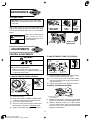
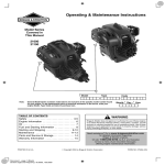
OIL
SAE Viscosity Grades
CAUTION: This engine is shipped from Briggs &
Stratton without oil. Check oil level before starting
engine. If you start the engine without oil, the engine
will be damaged beyond repair and will not be
covered under warranty.
**
*
OIL CAPACITY
°F -20
°C -30
Engine holds approximately 1-1/2 quarts (48 ounces or 1.4
liters) when changing oil and filter.
0
-20
20
-10
32
0
40
60
10
80
20
100
30
40
STARTING TEMPERATURE RANGE ANTICIPATED BEFORE NEXT OIL CHANGE
TYPE OF OIL TO USE
• Use a high quality detergent oil classified “For Service
SF, SG, SH, SJ” or higher, such as Briggs & Stratton
30W, Part Number 100005 (20 oz) or 100028 (48 oz).
• Do not use special additives.
• Choose a viscosity according to the table opposite.
*
CAUTION: Air cooled engines run hotter than
automotive engines. The use of non-synthetic
multi-viscosity oils (5W-30, 10W-30, etc.) in
temperatures above 40° F (4° C) will result in higher
than normal oil consumption. When using a
multi-viscosity oil, check oil level more frequently.
** CAUTION: SAE 30 oil, if used below 40° F (4° C),
will result in hard starting and possible engine bore
damage due to inadequate lubrication.
Note: Synthetic oil meeting ILSAC GF-2, API
certification mark and API service symbol
(shown at left) with “SJ/CF ENERGY CONSERVING” or higher, is an acceptable oil at all
temperatures. Use of synthetic oil does not
alter required oil change intervals.
CHECKING AND ADDING OIL
• Check oil level before starting the engine.
• Check level daily, or after every eight (8) hours.
• Keep oil level at FULL.
• Do not overfill.
Oil filling procedure: first add 1 quart (32 ounces or 1 liter). Start and run engine at idle for 30 seconds. Shut engine off and
wait 30 seconds. Then add more oil slowly to bring level to Full mark on dipstick.
Oil checking procedure: before starting engine, check oil level.
Oil Fill
Dipstick
[1]
Ï
Ï
Place engine level.
Clean around oil fill and dipstick.
ÏÏ
ÏÏ
ÏÏ
ÏÏ
[4]
Remove oil fill cap (if
equipped). Pour oil slowly.
[5]
Ï
Ï
Remove dipstick and
wipe clean with cloth.
[3]
Then push dipstick back
in and remove to check
oil level.
FULL
Fill to FULL line on dipstick – recheck.
7
Document: - page 7 (Black)
Screen angle and frequency: 45.0000, 150.0000
[2]
FULL
[6]
Replace dipstick firmly.
FUEL
TYPE OF FUEL TO USE
GASOLINE POWERED ENGINES
NATURAL (NG) / LIQUID PROPANE (LPG)
GAS POWERED ENGINES
• Use clean, fresh, regular unleaded gasoline with a
minimum of 85 octane. Fresh fuel prevents gum from
forming in the fuel system or on essential carburetor parts.
Purchase fuel in quantity that can be used within 30 days.
• Do not use gasoline which contains Methanol.
• Do not mix oil with gasoline.
• For engine protection use Briggs & Stratton Gasoline
Additive available from your Authorized Briggs &
Stratton Dealer (P/N 5041 or single use pouch).
• The gasoline engine is certified to operate on gasoline.
Exhaust Emission Control System: EM (Engine
Modifications).
• Use clean, dry fuel, free of moisture or any particulate
material. Using fuels outside the following recommended values may cause performance problems.
• In engines set up to run on LPG, commercial grade
HD5 LPG is recommended. Recommended fuel
composition is fuel with a minimum fuel energy of
2500 BTU’s/ft 3 with maximum propylene content of
5% and butane and heavier gas content of 2.5% and
minimum propane content of 90%.
• NG or LPG engines are certified to operate on natural
or liquid propane gas.
WARNING
CAUTION: Some fuels, called oxygenated or
reformulated gasoline, are gasoline blended with
alcohols or ethers. Excessive amounts of these
blends can damage the fuel system or cause
performance problems. If any undesirable operating symptoms occur, use gasoline with a lower
percentage of alcohol or ether.
The equipment on which this engine is mounted is
equipped with an automatic safety gas “fuel
lock-off” valve. DO NOT operate the equipment if
the “fuel lock-off” valve is missing or inoperative.
ADDING FUEL
GASOLINE POWERED ENGINES
NATURAL (NG) / LIQUID PROPANE (LPG)
GAS POWERED ENGINES
WARNING
• Read the operating instructions supplied by the
equipment manufacturer for information on refueling
natural or LP gas engine.
• Turn engine OFF and let engine cool at least 2
minutes before removing gas cap.
• Fill fuel tank outdoors or in well-ventilated area.
• Keep gasoline away from sparks, open flames,
pilot lights, heat, and other ignition sources.
• If fuel spills, wait until it evaporates before
starting engine.
[1]
Remove cap. Fill tank to approximately 1-1/2
inches below top of neck to allow for fuel
expansion. Be careful not to overfill.
Briggs & Stratton Smart-fill) Fuel Can fills to
the correct level and automatically shuts off,
reducing spills and emissions.
[2]
Replace cap before starting.
8
Document: - page 8 (Black)
Screen angle and frequency: 45.0000, 150.0000
STARTING AND STOPPING
OIL PRESSURE SWITCH
WARNING
If engine is equipped with an oil pressure switch, the switch
will either activate a warning device or stop the engine
when the engine runs low on oil. (Read the operating
instructions supplied by the equipment manufacturer to
determine how your engine is equipped.)
• Do not use pressurized starting fluids.
• Vapors are flammable.
BEFORE STARTING – LPG / NG ENGINES
The LPG / NG mixer is equipped with solenoid,
fuel inlet, 12 volt connector, and equipped for a fuel
lock-off valve.
12 VOLT CONNECTOR
FUEL
LOCK-OFF
VALVE
FUEL INLET
CAUTION:
When operating on LPG fuel, 12 volts
MUST be supplied to the connector.
When operating on NG fuel, 12 volts
MUST NOT be supplied to connector.
Failure to do so, may cause engine
damage.
SOLENOID
REWIND (MANUAL) STARTING – ALL ENGINES
[1]
Check oil level (see p. 7).
ÏÏ
Ï
Note: NG /
LPG
ENGINES
– skip steps
[2] and [3].
FULL
[2]
[3]
Choke
Open fuel shut-off valve
(if equipped).
Move choke control to
CHOKE or START.
WARNING
STOP
[5]
[7]
RUN
Push rocker switch
(if equipped) to ON or
RUN.
[6]
Grasp rope handle. Pull slowly until
resistance is felt, then pull rapidly to
start engine and avoid kickback.
[4]
Move throttle (if equipped)
to FAST. Operate engine
with throttle in FAST.
Allow engine to warm up.
Choke Equipped Engines: In warm
weather temperatures, move choke
control lever toward RUN slowly over
several seconds, in cold weather allow
engine to run smoothly before each
change. Operate with choke in RUN.
STOPPING
CAUTION: Do not stop
engine by moving choke
control to CHOKE.
Backfire, fire or engine
damage could occur.
[1]
Move
throttle (if
equipped)
to SLOW,
then
to
STOP.
9
Document: - page 9 (Black)
Screen angle and frequency: 45.0000, 150.0000
[2]
Push rocker switch
(if equipped) to
OFF or STOP.
[3]
Close fuel shut-off
valve (if equipped).
STOP
RUN
STARTING AND STOPPING
ELECTRIC (KEY) STARTING (if equipped) – ALL ENGINES
[1]
Check oil level (see p. 7).
ÏÏ
ÏÏ
ÏÏ
FULL
STOP
[5]
Note: NG /
LPG
ENGINES
– skip steps
[2] and [3].
Choke
Open fuel shut-off valve
(if equipped).
[3] Move choke control to
CHOKE or START.
[2]
CAUTION:
Use short starting
cycles (5 seconds, wait
one minute between
cycles).
Follow
equipment
manufacturer’s recommendations for charging battery.
RUN
Push rocker switch
(if equipped) to ON
or RUN.
[6]
Insert key and
turn to START.
[1]
Move
throttle (if
equipped)
to SLOW,
then
to
STOP.
[4]
[7]
Move throttle (if equipped)
to FAST. Operate engine
with throttle in FAST.
Allow engine to warm up.
Choke Equipped Engines:
In warm weather temperatures, move choke control
lever toward RUN slowly over
several seconds, in cold
weather allow engine to run
smoothly
before
each
change. Operate with choke
in RUN.
STOPPING
CAUTION:
Do not stop engine
by moving choke
control to CHOKE.
Backfire, fire or
engine damage
could occur.
STOP
RUN
[2]
Turn key to OFF. Remove key and store out of reach of children.
[3]
Push rocker switch (if equipped) to OFF or STOP.
[4]
Close fuel shut-off valve (if equipped).
STARTING AND OPERATING TIPS – ALL ENGINES
♦ Use correct type of oil for expected starting
temperature.
♦ Remove external equipment/engine loads. (See
equipment operating instructions.)
♦ Periodically remove any debris buildup from the
machine.
♦ After engine has started, let it warm up several
seconds to several minutes, depending on outside
temperature.
♦ For maximum performance and life, operate engine
throttle in FAST.
10
Document: - page 10 (Black)
Screen angle and frequency: 45.0000, 150.0000
MAINTENANCE
Maintenance, replacement or repair of the emission
control devices and systems may be performed by any
nonroad engine repair establishment or individual.
However, to obtain no charge repairs under the terms and
provisions of the Briggs & Stratton warranty statement, any
service or emission control part repair or replacement must
be performed by a factory authorized dealer.
Perform task at hourly
or calendar interval,
whichever comes first.
Check oil level
Change oil
CHANGING OIL
Yearly
Task
100 Hours or
Every Season
Regular maintenance will improve the performance and
extend the life of the engine. See any Authorized Briggs &
Stratton Dealer for service. Use only genuine Briggs &
Stratton parts. Other parts may not perform as well,
may damage the engine, and may result in injury. In
addition, use of other parts may void your warranty.
50 Hours or
Every Season
EMISSION CONTROL
Every 8 Hours
or Daily
25 Hours or
Every Season
MAINTENANCE
PIPE
*
Change oil filter
(if equipped)
Service air cleaner
pre-cleaner
**
Service air cleaner
cartridge
Inspect spark arrester
(if equipped)
Typical drain plug
WARNING
**
Clean oil cooler
(if equipped)
**
Clean cooling system
**
[3]
[4]
Clean/replace
spark plugs
Clean/replace in-line
fuel filter (if equipped)
Check valve clearance
Check valve clearance
on NG / LPG Engines
[1]
Place engine level.
[2]
Disconnect spark plug
wires and keep away
from spark plugs. Disconnect battery (if equipped with electric starter)
at negative terminal.
With engine OFF but still warm remove oil drain
plug and drain oil into appropriate receptacle.
Reinstall drain plug. Remove oil fill cap (if equipped).
[5]
Oil filling procedure: first add 1 quart (32 ounces
or 1 liter). Start and run engine at idle for 30
seconds. Shut engine off and wait 30 seconds.
Then add more oil slowly to bring level to Full mark
on dipstick. Do not overfill.
Note: Engine holds approximately 1-1/2 quarts
(48 ounces or 1.4 liters) when changing oil and filter.
[6]
*
Change oil after first 5 to 8 hours of use, then every
50 hours or every season. Change oil every 25 hours
when operating the engine under heavy load or in high
temperatures.
** Clean more often under dusty conditions or when
airborne debris is present. Replace air cleaner parts, if
very dirty.
CAUTION: Used oil is a hazardous waste product.
Dispose of used oil properly. Do not discard with
household waste. Check with your local authorities,
service center, or dealer for safe disposal/recycling
facilities.
11
Document: - page 11 (Black)
Screen angle and frequency: 45.0000, 150.0000
OIL
DRAIN
PLUG
Replace oil fill cap, if equipped,
and dipstick.
MAINTENANCE
ENGINE AND ENGINE PARTS
We recommend that you see an authorized Briggs & Stratton Service Dealer for all maintenance and service of the engine
and engine parts. Use only genuine Briggs & Stratton parts.
If you perform any maintenance on the engine, first disconnect the spark plug wires
from the spark plugs, and disconnect the battery at the negative terminal (electric
WARNING
starter engines only) to prevent unintentional sparking. Unintentional sparking can
result in fire or electric shock. Unintentional start-up can result in entanglement,
traumatic amputation or laceration. Use only correct tools.
• Do not strike the flywheel with a hammer or hard object because the flywheel may
later shatter during operation.
• Do not tamper with governor spring, links or other parts to increase engine speed.
WARNING
CHANGING OIL FILTER (if equipped)
OIL PRESSURE
Change oil filter after every 100 hours or every season.
[1] Drain engine oil and remove oil filter.
[2]
Before installing new filter, lightly oil filter gasket
with fresh, clean oil.
[3]
Screw filter on by hand until gasket contacts oil
filter adapter. Tighten 1/2 to 3/4 turn more.
[4]
Add fresh oil. Fill to FULL line on dipstick.
[5]
Start and run engine at idle to check for leaks.
[6]
Stop engine. Re-check oil level. Add oil if required.
If oil pressure drops below 1-4 psi (.1-.2 kg/cm2), an oil
pressure switch (if equipped) will either activate a warning
device or stop the engine. Check oil level with dipstick. If oil
level is between ADD and FULL mark on dipstick, do not try
to restart engine. Contact an Authorized Briggs & Stratton
Service Dealer. Do not operate engine until oil pressure is
corrected.
If oil level is below ADD mark on dipstick, add oil to bring
level to FULL mark. Restart engine and check oil pressure.
If pressure is normal, continue to operate engine.
OIL PRESSURE
SWITCH
Note: Oil pressure gauge, if engine is equipped, is supplied
by manufacturer of equipment.
OIL FILTER
MUFFLER
FUEL FILTER (if equipped)
Replacement parts for the
muffler must be the same and
installed in the same position
as the original parts, otherwise fire can occur.
If muffler is equipped with spark
arrester
screen,
remove
screen for inspection. Replace screen if damaged or plugged.
WARNING
WARNING
FUEL SYSTEM
WARNING
FILTER
ÎÎÎ
Î
Replacement parts for fuel
system (cap, hoses, tanks,
filters, etc.) must be the same
as original parts, otherwise
fire can occur.
PART NO. 493629
(WITH FUEL PUMP)
12
Document: - page 12 (Black)
Screen angle and frequency: 45.0000, 150.0000
Drain fuel tank or close fuel
shut-off valve before replacing fuel filter. Otherwise, fuel
can leak out, creating a fire/
explosion hazard.
FILTER
PART NO. 298090 or 5018
(WITHOUT FUEL PUMP)
FILTER
PART NO. 808116 (WITH
FUEL TANK, IF EQUIPPED)
MAINTENANCE
AIR CLEANER
All engines have a round air cleaner cartridge. In addition,
some engines have a pre-cleaner.
Pre-cleaner
To clean pre-cleaner (if equipped), separate it from
cartridge and wash in liquid detergent and water. Squeeze
dry in a clean cloth.
CAUTION: Do not use pressurized air or solvents to
clean cartridge. Pressurized air can damage
cartridge; solvents will dissolve cartridge.
Removing/Installing Air Cleaner without Fuel Tank
Removing/Installing Air Cleaner with Fuel Tank
KNOB
CLIPS
COVER
COVER
“UP”
KNOB
PLATE
CARTRIDGE
CARTRIDGE
PRE-CLEANER
and CARTRIDGE
FOAM
PRE-CLEANER
PRE-CLEANER
ÎÎ
Î
Î
ÎÎ
BASE
BODY
Air cleaner (if equipped with fuel tank)
Dual element air cleaner
[1]
[2]
[3]
[4]
[5]
Unhook clips on both sides of cover and remove cover.
Remove knob and plate. Carefully remove air cleaner
assembly to prevent debris from entering carburetor.
Reassemble clean (or new) pre-cleaner on clean (or
new) cartridge.
Reinstall air cleaner assembly, plate and knob.
Replace cover and reattach clips to body.
SPARK PLUG
[1]
Remove knobs and cover.
[2]
Remove nut, plate and carefully lift air cleaner
assembly (pre-cleaner and cartridge) off stud.
[3]
Reinstall clean (or new) air cleaner assembly firmly in
base. Reinstall plate (top side marked “UP”) and nut.
[4]
Reinstall cover. Tighten knobs securely.
OIL COOLER (if equipped)
Use only Briggs & Stratton Spark Tester (part number
19368) to check for spark.
Note: In some areas, local
law requires using resistor
spark plug to suppress ignition signals. If this engine
was originally equipped with
resistor spark plug, use
same type for replacement.
Clean oil cooler of
all debris and chaff.
.030” (0.76 mm)
WIRE GAGE
AIR COOLING SYSTEM
Debris may clog the
engine’s air cooling
system.
Remove
blower housing and
clean area shown to
prevent overheating
and engine damage.
NUT
PLATE
VALVE CLEARANCE
CLEAN ALL
AREAS
GASOLINE ENGINES –
Check valve clearance yearly. (See Tune-up
Specifications on page 6).
NG / LPG ENGINES –
Valve clearance must be checked after every
100 hours of operation. Adjust if necessary.
13
Document: - page 13 (Black)
Screen angle and frequency: 45.0000, 150.0000
MAINTENANCE
CLEANING DEBRIS
CAUTION: Do not use water to clean engine parts.
Water could contaminate fuel system. Use a brush
or dry cloth.
CLEAN
Daily or before every use, clean accumulated debris from
engine. Keep linkage, springs and controls clean. Keep
area around and behind muffler free of any combustible
debris.
WARNING
CLEAN
Linkage, Springs
and Controls
CLEAN
Finger
Guard
Rotating
Screen
SPARK
ARRESTER
Engine parts should be kept
clean to reduce the risk of
overheating and ignition of accumulated debris.
Muffler and
Spark Arrester
CLEAN
ADJUSTMENTS
CONTROL ADJUSTMENTS
TO ADJUST REMOTE THROTTLE CONTROL
WARNING
CASING
CLAMP
SCREW
Prevent unintentional starting.
Before performing adjustments:
• Remove spark plug wires from spark plugs.
• Disconnect battery at negative terminal (only
engines with electric start).
THROTTLE STOP
[1]
TO ADJUST REMOTE CHOKE CONTROL
[2]
WIRE AND
CASING
SWIVEL
[3]
EXHAUST
MANIFOLD
Remove air cleaner. Move throttle control to FAST.
(Swivel should be against throttle stop.)
If not, loosen casing clamp screw. Move casing
and wire in direction shown by arrow until swivel is
against throttle stop.
Tighten casing clamp screw. Replace air cleaner.
TO ADJUST GOVERNED IDLE SPRING
PULL
TO CHOKE
SCREW
CHOKE
CLOSED
[1]
[2]
[3]
[4]
[5]
Remove air cleaner.
Move choke control to CHOKE or START position.
(Carburetor choke should be completely closed.)
If not, loosen casing clamp screw.
Then move casing, wire and engine choke lever in
direction shown until choke is completely closed.
Tighten casing clamp screw. Replace air cleaner.
GOVERNED IDLE SPRING
(RED OR WHITE)
[1]
[2]
14
Document: - page 14 (Black)
Screen angle and frequency: 45.0000, 150.0000
EXHAUST
MANIFOLD
Readjust the idle speed to 1200 rpm, if governed idle
spring is red, or 900 rpm, if governed idle spring is white.
Release carburetor throttle lever. Move throttle
control to FAST position. Engine should accelerate
smoothly. If it does not, readjust idle mixture valves
slightly counterclockwise.
ADJUSTMENTS
CARBURETOR / FUEL MIXER ADJUSTMENT
WARNING
The manufacturer of the equipment on which this engine is installed specifies top
speed at which the engine will be operated. DO NOT EXCEED this speed.
GASOLINE OPERATED ENGINES
The carburetor on this engine is low emission. It is
equipped with an idle mixture valve with a limiter (see
inset), which allows some adjustment, and an idle speed
adjustment screw. DO NOT remove limiter caps. DO NOT
force beyond limits. Air cleaner and air cleaner cover must
be assembled to carburetor before starting engine.
Single barrel carburetor
IDLE SPEED
SCREW
TO ADJUST CARBURETOR
[1]
[2]
[3]
[4]
[5]
[6]
LIMITER
CAP
CARBURETOR
THROTTLE
LEVER
Start engine and warm up approximately 5 minutes
before adjusting.
With engine running, place throttle control in SLOW.
Rotate carburetor throttle lever against the idle speed
screw and hold it.
Turn idle speed screw to obtain 1400 rpm (1200 rpm
on two barrel carburetor).
While still holding carburetor throttle lever against idle
speed screw, turn idle mixture valve with limiter cap
screw midway between limits. DO NOT remove limiter
caps. DO NOT force beyond limit.
On two barrel carburetor: set cylinder #1 idle mixture
valve midway between limits. Then set cylinder #2 idle
mixture valve midway between limits, while holding
carburetor throttle lever against idle speed screw.
IDLE
MIXTURE
VALVE
Two barrel carburetor
CARBURETOR
THROTTLE
LEVER
IDLE SPEED
SCREW
IDLE MIXTURE
VALVES
CYL # 1
CYL # 2
Note: Engines operated at about 3000 or higher (900 meters or
higher) above sea level may require a high altitude carburetor
main jet. If erratic performance is observed, contact a Briggs &
Stratton Authorized Service Dealer for installation of a high
altitude carburetor main jet.
ON NG/LPG OPERATED ENGINES
ADJUSTING FUEL MIXER
If adjustment is needed, see a Briggs & Stratton Authorized Service Dealer who has been licensed by the state or local
municipality (if required) in which the service is performed. Mixer adjustment requires special equipment and a qualified
technician. DO NOT remove limiter caps. DO NOT force beyond limits.
15
Document: - page 15 (Black)
Screen angle and frequency: 45.0000, 150.0000
SERVICE & STORAGE
SERVICE
STORAGE
See an Authorized Briggs & Stratton Service Dealer. Each
one carries a stock of Genuine Briggs & Stratton Parts and
is equipped with special service tools. Trained mechanics
assure expert repair service on all Briggs & Stratton
engines. Only dealers advertising as “Authorized Briggs &
Stratton” are required to meet Briggs & Stratton standards.
Engines stored over 30 days need special attention.
[1] While engine is still warm, change oil.
[2] Remove spark plugs and pour about 1 oz. (30 ml) of
engine oil into each cylinder. Replace spark plugs and
crank slowly to distribute oil.
[3] Clean engine of surface debris, chaff or grass.
When you purchase equipment powered by a
Briggs & Stratton engine, you are assured of
highly skilled, reliable service at more than
30,000
Authorized
Service
Dealers
worldwide, including more than 5,000 Master
Service Technicians. Look for these signs
wherever Briggs & Stratton service is offered.
You may locate your nearest Authorized Briggs & Stratton
Service Dealer in our dealer locator map on our web site
111
or in the “Yellow Pages”
directory under “Engines, Gasoline” or “Gasoline
Engines,” or “Lawn Mowers” or similar category.
An illustrated shop manual includes common specifications and detailed information covering adjustment, tune-up and
repair of Briggs & Stratton OHV, twin
cylinder, 4 cycle engines. It is available for
purchase from an Authorized Briggs &
Stratton Service Dealer or you can order it
from the factory. Write: Briggs & Stratton
Corporation, Attn: Service Division
Part No. 272144
P. O. Box 1144, Milwaukee, WI 53201
[4]
WARNING
Store in a clean, dry area. Do
not store in same area as a
stove, furnace, water heater, or
other appliance that uses a pilot
light or has a device that can
create a spark.
On Gasoline Engines: To prevent gum from forming in
fuel system or on essential carburetor parts:
a) if fuel tank contains oxygenated or reformulated gasoline
(gasoline blended with an alcohol or an ether), run engine
until it stops from lack of fuel, or b) if fuel tank contains
gasoline, either run engine until it stops from lack of fuel, or
add a gasoline additive to the gas in the tank. (See parts list.
Single – use pouches of gas additive are available from your
service dealer.) If you use a gas additive, run the engine for
several minutes to circulate the additive through the
carburetor. Then, engine and fuel can be stored up to 24
months.
PARTIAL LIST OF GENUINE BRIGGS & STRATTON PARTS
Part
Briggs & Stratton Part No.
Part
Air filter cartridge (without fuel tank)
394018
(model 380400, 381400 only – use 692519)
Air filter pre-cleaner (without fuel tank)
272490
(model 380400, 381400 only – use 692520)
Air filter pre-cleaner/cartridge (without fuel tank)
5050D
(model 380400, 381400 only – use 5120A)
Air filter cartridge (with fuel tank)
393957
Air filter pre-cleaner (with fuel tank)
271794
Oil
100005 or 100028
Oil filter (3-1/2 in. long)
491056
Oil filter (2-1/4 in. long)
492932 or 5049
16
Document: - page 16 (Black)
Screen angle and frequency: 45.0000, 150.0000
Briggs & Stratton Part No.
Fuel filter (with fuel pump)
493629
Fuel filter (without fuel pump)
298090 or 5018
Fuel filter (with fuel tank)
808116
Gas additive
5041
Resistor spark plug (Champion RC12YC)
491055
Resistor spark plug (Champion RC14YC)
496018
Long life platinum spark plug
5066
(used on most OHV engines)
Spark plug wrench
19374
Spark tester
19368
Oil pump kit
5056
(uses standard electric drill to remove oil from engine quickly)
LIMITED WARRANTY
Briggs & Stratton Corporation will repair or replace, free of charge, any part(s) of the engine that is defective in material or workmanship or both.
Transportation charges on parts submitted for repair or replacement under this warranty must be borne by purchaser. This warranty is effective for the
time periods and subject to the conditions stated below. For warranty service, find the nearest Authorized Service Dealer in our dealer locator map
at www.briggsandstratton.com, or by calling 1-800-233-3723, or as listed in the ‘Yellow Pages’.
THERE IS NO OTHER EXPRESS WARRANTY. IMPLIED WARRANTIES, INCLUDING THOSE OF MERCHANTABILITY AND FITNESS FOR A
PARTICULAR PURPOSE, ARE LIMITED TO ONE YEAR FROM PURCHASE, OR TO THE EXTENT PERMITTED BY LAW ANY AND ALL IMPLIED
WARRANTIES ARE EXCLUDED. LIABILITY FOR INCIDENTAL OR CONSEQUENTIAL DAMAGES ARE EXCLUDED TO THE EXTENT
EXCLUSION IS PERMITTED BY LAW. Some states or countries do not allow limitations on how long an implied warranty lasts, and some states or
countries do not allow the exclusion or limitation of incidental or consequential damages, so the above limitation and exclusion may not apply to you.
This warranty gives you specific legal rights and you may also have other rights which vary from state to state and country to country.
( )(
"
r
(Sleeve Bore)
!"
(Kool Bore)
!# $
%&r
%!
%45
'
2 years
2 years
1 year
1 year
90 days
90 days
)*
Consumer Use
Commercial Use
*
2 years
1 year
Note the following special warranty periods: 2 years for Classic engines in the European Union and Eastern European countries, for all consumer products in
the European Union, and for emission control systems on engines certified by EPA and CARB. 5 years for consumer use, 90 days for commercial use of Touch-NMow starter on Quantum and Intek engines. Engines used in competitive racing or on commercial or rental tracks are not warrantied.
The warranty period begins on the date of purchase by the first retail consumer or commercial end user, and continues for the period of time stated in the table
above. “Consumer use” means personal residential household use by a retail consumer. “Commercial use” means all other uses, including use for commercial,
income producing or rental purposes. Once an engine has experienced commercial use, it shall thereafter be considered as a commercial use engine for purposes of this warranty.
NO WARRANTY REGISTRATION IS NECESSARY TO OBTAIN WARRANTY ON BRIGGS & STRATTON PRODUCTS. SAVE YOUR PROOF OF PURCHASE
RECEIPT. IF YOU DO NOT PROVIDE PROOF OF THE INITIAL PURCHASE DATE AT THE TIME WARRANTY SERVICE IS REQUESTED, THE
MANUFACTURING DATE OF THE PRODUCT WILL BE USED TO DETERMINE THE WARRANTY PERIOD.
( ( !
" #
$ # !
$ !
% &
' # ( " & #
! "
# $
! ! %
!! ! "
&
! '
% ) *+,-' ./' 0 *+& &1& +' 2,&
,+$3$2- +$33 &+&&,2 *+&
4 ' 5.
6
7 -# # 5/ 8 ! * 2
9:;)6
; * # 5# <=
+ 6 ,$- 3+ ' + , $
9 + % > 8 8
5 17
Engwnty1-03 - page 1 (Black)
Screen angle and frequency: 45.0000, 150.0000
8
,8!
8 6 +
, $
? * 8 5. 6 + , $
< ' # "
# 8 @ # # # % " 8 ): +
8 % )) ' !"! !!
! !( )"" * +
,
&
-!( + . !
/0 1"2 !
/
"
3
2 /3
"
2 /4
52 "&
! !'!! +,- . /! !" ! +,
. ( 0!& !"! "1 +(22 ,
&! !! 1& 1 & +#3 )/" 1 . 4!,
EMISSION CONTROL WARRANTY COVERAGE IS APPLICABLE TO CERTIFIED ENGINES PURCHASED IN CALIFORNIA IN 1995 AND THEREAFTER, WHICH ARE USED IN CALIFORNIA, AND TO CERTIFIED MODEL YEAR 1997 AND LATER ENGINES WHICH ARE PURCHASED AND
USED ELSEWHERE IN THE UNITED STATES (AND AFTER JANUARY 1, 2001 IN CANADA).
/! ( &! !! )/" 1 &
The California Air Resources Board (CARB), U.S.
EPA and B&S are pleased to explain the Emission
Control System Warranty on your model year
2002 and later small off-road engine (SORE). In
California, new small off-road engines must be designed, built and equipped to meet the State’s
stringent anti-smog standards.
Elsewhere in the United States, new non-road,
spark-ignition engines certified for model year
1997 and later must meet similar standards set
forth by the U.S. EPA. B&S must warrant the emission control system on your engine for the periods
of time listed below, provided there has been no
abuse, neglect or improper maintenance of your
small off-road engine.
Your emission control system includes parts
such as the carburetor, air cleaner, ignition system, muffler and catalytic converter. Also included may be connectors and other emission
related assemblies.
Where a warrantable condition exists, B&S will
repair your small off-road engine at no cost to
you including diagnosis, parts and labor.
! &! !! )/" 1 !0
Small off-road engines are warranted relative to emission control parts defects for a period of two years, subject to provisions set forth below. If any
covered part on your engine is defective, the part will be repaired or replaced by B&S.
#3 1 '!4
As the small off-road engine owner, you are responsible for the performance of the required
maintenance listed in your Operating and Maintenance Instructions. B&S recommends that
you retain all your receipts covering maintenance on your small off-road engine, but B&S
cannot deny warranty solely for the lack of receipts or for your failure to ensure the performance of all scheduled maintenance.
As the small off-road engine owner, you should
however be aware that B&S may deny you warranty coverage if your small off-road engine or a
part has failed due to abuse, neglect, improper
maintenance or unapproved modifications.
You are responsible for presenting your small
off-road engine to an Authorized B&S Service
Dealer as soon as a problem exists.
The undisputed warranty repairs should be
completed in a reasonable amount of time, not
to exceed 30 days.
If you have any questions regarding your warranty rights and responsibilities, you should contact a B&S Service Representative at
1-414-259-5262.
The emission warranty is a defects warranty.
Defects are judged on normal engine performance. The warranty is not related to an in-use
emission test.
! &! !! )/" 1 !0!
The following are specific provisions relative to your Emission Control Defects Warranty Coverage. It is in addition to the B&S engine warranty for nonregulated engines found in the Operating and Maintenance Instructions.
1. Warranted Parts
2. Length of Coverage
set forth in the B&S Engine Warranty Policy.
B&S is not liable to cover failures of WarB&S warrants to the initial owner and each
Coverage under this warranty extends only
ranted Parts caused by the use of add-on,
subsequent purchaser that the Warranted
to the parts listed below (the emission connon-original, or modified parts.
Parts shall be free from defects in materials
trol systems parts) to the extent these parts
and workmanship which caused the failure 5. Maintenance
were present on the engine purchased.
of the Warranted Parts for a period of two
Any Warranted Part which is not scheduled
a. Fuel Metering System
years from the date the engine is delivered to
for replacement as required maintenance or
•
Cold start enrichment system
a retail purchaser.
which is scheduled only for regular inspec•
Carburetor and internal parts
3. No Charge
tion to the effect of “repair or replace as nec•
Fuel Pump
essary” shall be warranted as to defects for
Repair or replacement of any Warranted
b. Air Induction System
the warranty period. Any Warranted Part
Part will be performed at no charge to the
which is scheduled for replacement as re•
Air cleaner
owner, including diagnostic labor which
quired maintenance shall be warranted as to
leads to the determination that a Warranted
•
Intake manifold
defects only for the period of time up to the
Part
is
defective,
if
the
diagnostic
work
is
c. Ignition System
first scheduled replacement for that part. Any
performed at an Authorized B&S Service
•
Spark plug(s)
replacement part that is equivalent in perforDealer. For emissions warranty service
•
Magneto ignition system
mance and durability may be used in the percontact your nearest Authorized B&S Serformance of any maintenance or repairs.
vice Dealer as listed in the “Yellow Pages”
d. Catalyst System
The owner is responsible for the perforunder “Engines, Gasoline,” “Gasoline En•
Catalytic converter
mance of all required maintenance, as degines,”
“Lawn
Mowers,”
or
similar
category.
•
Exhaust manifold
fined in the B&S Operating and Maintenance
4. Claims and Coverage Exclusions
•
Air injection system, Pulse valve
Instructions.
Warranty claims shall be filed in accordance
e. Miscellaneous Items
with the provisions of the B&S Engine War- 6. Consequential Coverage
•
Vacuum, temperature, position,
ranty Policy. Warranty coverage shall be exCoverage hereunder shall extend to the failtime sensitive valves
cluded for failures of Warranted Parts which
ure of any engine components caused by
and switches
are not original B&S parts or because of
the failure of any Warranted Part still under
•
Connectors and assemblies
abuse, neglect or improper maintenance as
warranty.
' / , , , & !
*A 84;?)?? 5, * *6
5,819,513
5,606,948
5,497,679
5,235,943
6,325,036
6,077,063
5,813,384
5,606,851
5,320,795
5,197,425
6,284,123
6,064,027
5,548,955
5,271,363
5,197,422
5,765,713
6,260,529
6,014,808
5,645,025
5,546,901
5,269,713
5,191,864
6,230,678
5,894,715
6,202,616
5,852,951
5,642,701
5,503,125
5,265,700
5,188,069
6,116,212
5,823,153
5,619,845
5,501,203
5,243,878
5,186,142
18
Engwnty1-03 - page 2 (Black)
Screen angle and frequency: 45.0000, 150.0000
5,138,996
5,086,890
5,070,829
5,058,544
5,040,644
5,009,208
4,996,956
4,977,879
4,971,219
4,895,119
4,819,593
4,719,682
4,633,556
4,630,498
4,522,080
4,520,288
4,512,499
4,453,507
4,430,984
DES. 308,871
DES. 308,872
DES. 309,457
DES. 356,951
DES. 361,771
DES. 375,963
! "# $%& ! %% ' %
! "
#$%%! %%& !'
(# $# (' )**+ # , - ' .
# ('/ -
0 !'" (# " )**1 # .
, - ' ## $# # 0 %# )
2, 344) "5
6 7 & &/ & 897 7 :8
55 % &; <= = >?8 97<8 8 < : 8? 3444 9 9 '5 6/ := 8 < : @ 7A/ 7 99 7 = 5 = / := 8 < B
C 8 769 8? )**1 / : 7 8 8.
8 : 55 %5 & ; >?8 7D 97<.
8 : 8 9 8 89 77/ 6 6 CE
C/ 97 95
, >?8 7D 97<8 78 ?7 7C/ 6 B
/ >?8 / 7= 7: 7>5 78 77 ?7 9 B 985
> 7 B / &; 9 8 : 8 < 7
7/ ?7 8 F:5
8 < 7 9679 ?7 >?8 7D.
97<8 9 3 / E = 7 9 775 8.
?7 : 8 7: 7 967/ 99 879 &;5
9 8 < / : @ C : B =97
9 : 8 9 5 &; : 78.
8 7: A 7: := : 8 < .
/ 8 &; 6 C7 A 96 : :
97<97 88 5
9 8 < / : :G @ 689 &; 6
< 7 9679 : 8 : 8 B
8 C6/ 97/ 77 867 :95
, :G C9 : 8 < B 9 9 &;
D : C?85 9 : @ 7899 9 C : =79 H4 E5
: :G :8 B : / : C9/ :G
788 :7 9 :7 &; 89 )I)I3+*+3J35
>?8 97<8 7 96795 967.
9 E9 67 8 85 9 B 97<8 6679 B 95
(% "# $%& %% "# ) $%&
'% %
( "# $%& 77 976 :8 B : >?8 7D 97<85 B &; 8 989 7
8 5
)5 # H5 7 (
7: 7 ?7 9 77 9 878 ?7 6679 7
>?8 7D 97<8 8 K 7 ?7 9 9 6 9/ 7 6 8 F: 7 6 98.
8 88 7<5
?7 967/ 7 B 7 7 6679
7<G
9 9 &;5 % : >?8 97<8/ 788.
5 >?8 7C
G
:7 9 9 &; 7< 9 E • >?8 7<8 98 B 6
: 79 C 8 B 7/ 79 85
• C I5 978 =7 7:5
• %8 B 7
978 : @ 7899 77 :7 C5 >?8 7 &;5 7: 9679 ?7 • ( B ?7 &; 7 C/ 97 95
• C 8
&; 7: 9679 ?7 6 CE
75 >?8 E/ 99 869 ?7 ?7 &; 5
• & 8
+5 • >?8 8 9789
?7 879 88 8 .
5 >?8 7>
69 8 7 9? 8 LM9 • : 7>
87 97MN 7 9679 9 5
• 7 97<8
?7 69 878 .
• >?8 E7 B 7 9679 8 9 8 : E
5 ?7 9 >?8 7< 89
8 878 9: 7 ?75 ?7 878 9: • 9/ 89/ 5
687 C9 @ 9 95 9 C =97 96 8 7
• 7 8C5
&; 95
35 (% J5 : 7
&; 9 7< C9 ?7 .
7: 77 9 B 9679 78 8 79 =8 :7 8? 6C7 7 967.
9679 8 ?7 7: 7
9 ?7 9 = B B 8.
99 :9 B 7<5
:5
* % '% $% $+,(+ $ $%- $% 8 769 768 = 8 98 6 7 & & 3/ : 667< 68 77 9 C9 >?8
98 " 5 68 9 9 9 8 & ; 5 9 8 8 77 7675
% '% $% 8C < 8 8 769 768 = 8 98 9: 9 9 8 9 5 79 : 9MO
.%%
8 769 768 )3+ < 85
+%
8 769 768 3+4 < 85
%
8 769 768 +44 < 85
% =8/ 8? 9 : 34 B 3+ < 95 % 79/ % '% $% 8 79 89 7 > 9: B )4 B )3 5
$ 8C 97 : 6 98 79 976 85 % $ C/ 8 975 68 9 68 < 9 985
/ 0 1 2333 * % % $% %-
? ) E 3444/ 7 8 &; 769 768 = 8 :8 98 :8 %7 7> % %< 35 % 8 769 %< 3/ 9 7689 98 89 9 8C < 8 7 8 6995 % 8 67 8 33+ 77/ 79 P )3+ </ & P 3+4 < P +44 <5 % 8 33+ 77 / 79 P 3+4 </ & P +44 < P )444 <5
878 8 8? 9 3*4444 H44444 IQ4 77/ H+4444 +14 77/ HQ4444 J31 775
% %- $%
- * %4O
Document: - page 1 (Black)
Screen angle and frequency: 45.0000, 150.0000
INFORMATIONS IMPORTANTES
CORPORATION BRIGGS & STRATTON
FAMILLE YBSXS.3192VA
274812
CE MOTEUR EST CONFORME AUX NORMES
ANTIPOLLUTION 2000 – 2001 DE CALIFORNIE
POUR LES PETITS MOTEURS HORS ROUTE ET
AUX NORMES ENVIRONNEMENTALES
AMÉRICAINES (EPA PHASE 2) POUR LES
PETITS MOTEURS HORS ROUTE. CONSULTEZ
LE MANUEL DU PROPRIÉTAIRE POUR LES
SPÉCIFICATIONS, L’ENTRETIEN ET LES
AJUSTEMENTS. CONFORME À LA PÉRIODE
D’ÉMISSION EPA : CATÉGORIE : C