1
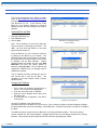
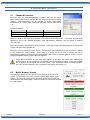
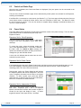
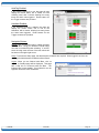
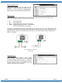
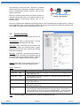
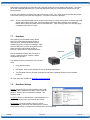
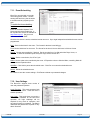
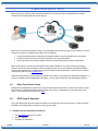
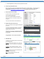
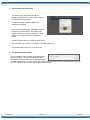
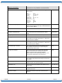
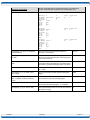
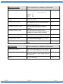
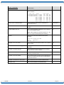
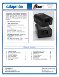
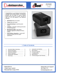
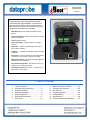
Web Enabled Power Switch 05/06/2014 Congratulations on purchasing the best network controlled power switch available. The iBoot-G2+ provides you the ability to reboot crashed devices with the click of a mouse. Be sure to read up on all the features of the iBoot-G2+ Including: Web Based setup and control with mobile browser support. Graceful Shutdown: attempt a soft shutdown or reboot before cycling power. Telnet setup and control Event Scheduling: Set power actions on regular intervals. Expansion: Add low cost iBoot-EXP units for up to three outlets controlled. AutoPing: equipment. I/O Control: Control or Monitor your own digital Inputs and Outputs. Use inputs to control the AC outlet. Management Utility: Easy Setup, Firmware upgrades and Reset to Factory Default Easy Software Integration: Use the DxP Protocol to build your own custom applications. New iBoot Cloud Service – BETA – Control all your iBoots from one web portal. Automatic monitoring and action for failed 1. Table of Contents 1. 2. 3. 4. 5. 6. 7. Table of Contents .................................... 1 Important Safety Instructions .................. 2 General Description ................................ 3 Hardware Installation .............................. 5 Initial Configuration ................................. 9 Web Browser Operation ........................ 11 Web Setup ............................................ 14 8. 9. 10. 11. 12. 13. 14. iBoot Cloud Service – BETA ................. 23 Command Line Interface ....................... 26 DxP Protocol ......................................... 34 Firmware Upgrades ............................... 34 Troubleshooting .................................... 35 Specifications ........................................ 36 Technical Support and Warranty .......... 37 2. Important Safety Instructions When using this product, basic safety precautions should always be followed to reduce the risk of fire, electric shock, and injury to persons, including the following: 1. 2. 3. 4. 5. 6. 7. 8. 9. 10. 11. 12. 13. 14. 15. 16. Read and understand all instructions. Follow all warnings and marked on the product. Unplug this product from the wall outlet before cleaning. Do not use liquid cleaners or aerosol cleaners. Use a damp cloth for cleaning. Do not use this product in an outdoor environment or near water, for example, near a bath tub, wash bowl, kitchen sink, or laundry tub, in a wet basement, or near a swimming pool. Do not place this product on an unstable cart, stand, or table. The product may fall, causing serious damage to the product. Slots and openings in this product and the back or bottom are provided for ventilation to protect it from overheating; these openings must not be blocked or covered. The openings should never be blocked by placing the product on the bed, sofa, rug, or other similar surface. This product should never be placed near or over a radiator or heat register. This product should not be placed in a built-in installation unless proper ventilation is provided. This product should be operated only from the type of power source indicated on the marking label. If you are not sure of the type of power supply to your home, consult your dealer or local power company. This product is equipped with a three wire grounding type plug, a plug having a third (grounding) pin. This plug will only fit into a grounding type power outlet. This is a safety feature. If you are unable to insert the plug into the outlet, contact your electrician to replace your obsolete outlet. Do not defeat the safety purpose of the grounding type plug. Do not use a 3-to2 prong adapter at the receptacle; use of this type adapter may result in risk of electrical shock and/or damage to this product. Do not allow anything to rest on the power cord. Do not locate this product where the cord will be abused by persons walking on it. Do not overload wall outlets and extension cords as this can result in the risk of fire or electric shock. Never push objects of any kind into this product through slots as they may touch dangerous voltage points or short out parts that could result in a risk of fire or electrical shock. Never spill liquid of any kind on the product. To reduce the risk of electrical shock, do not disassemble this product, but take it to a qualified serviceman when some service or repair work is required. Opening or removing covers may expose you to dangerous voltages or other risks. Incorrect re-assembly can cause electric shock when the appliance is subsequently used. Unplug this product from the wall outlet and refer servicing to qualified service personnel under the following conditions: a) When the power supply cord or plug is damaged or frayed. b) If liquid has been spilled into the product. c) If the product has been exposed to rain or water. d) If the product does not operate normally by following the operating instructions. Adjust only those controls that are covered by the operating instructions because improper adjustment of other controls may result in damage and will often require extensive work by a qualified technician to restore the product to normal operation. e) If the product has been dropped or has been damaged. f) If the product exhibits a distinct change in performance. Avoid using a telephone (other than a cordless type) during an electrical storm. There may be a remote risk of electric shock from lightning. Do not use the telephone to report a gas leak in the vicinity of the leak. Do not exceed the maximum output rating of the auxiliary power receptacle. Save These Instructions V140506E iBoot-G2+ Page 2 3. General Description The iBoot-G2+ is a network attached, IP addressed, web controlled AC power switch. Anyone with a web browser can access iBoot-G2+ to perform power On, Off or Power Cycle (Reboot or Power Burst). iBoot-G2+ access is password protected with user and administrator security levels. iBoot-G2+ features international standard IEC320 connections and is compatible with power mains worldwide. A simple Web browser interface makes it easy to control power from anywhere in the world with a click of a mouse. iBoot-G2+ also supports Telnet for text commands, as well as Dataprobe’s Exchange Protocol (DxP) for interfacing to a variety of Dataprobe products and custom software development. 3.1. • • • • Uses for iBoot Remote reboot of any device, routers, servers, kiosks, etc. The device to be rebooted need not be network attached. Secure sensitive devices by keeping them powered off when not in use. This prevents hackers from seeing them at all times. Power down equipment when not needed for power savings and to save on wear and tear. Power up alert devices like sirens, lamps, messages; or control environmental system like heaters, coolers pumps, etc. 3.2. Multiple Control Options In addition to the Web control capabilities, iBoot-G2+ features several other means to operate automatically or under computer control. AutoPing and Heartbeat: The AutoPing feature allows iBoot-G2+ to automatically detect failed equipment and perform a timed reboot or other power control function (like turning on an indicator or siren). You set up to four IP addresses to be periodically pinged. When iBoot-G2+ no longer detects a response from the address(es), the programmed power control function is actuated. The heartbeat function works in reverse; it looks for a message from a device and takes action when that message is no longer received. The heartbeat generator app installs in your server and allows the iBoot-G2+ to auto reboot when the server crashes. Telnet: iBoot’s Command Line Interface (CLI) allows direct control and setup through Telnet. USB: iBoot’s Command Line Interface (CLI) allows direct control and setup through the USB port. V140506E iBoot-G2+ Page 3 Dataprobe Exchange Protocol: iBoot-G2+ supports Dataprobe Exchange Protocol (DxP) This protocol allows Dataprobe products to communicate across networks, and allows developers to design custom applications to integrate iBoot-G2+ into custom applications. For more information about DxP, contact Dataprobe Applications Engineering and Support. 3.3. Expansion to Three Outlets iBoot-G2+ can be linked to two expansion units, iBoot-Exp to control three outlets. All three outlets are controlled and managed through the iBoot-G2+ web page and CLI. Each outlet is independently controlled. AutoPing and Heartbeat can be used to control the main and expansion units independently as well. Expand to 3 Outlets with iBoot-Exp 3.4. Expansion to GPIO When not used for expansion to iBoot-Exp, the Expansion Ports on the iBoot-G2+ can be used as general purpose I/O (GPIO) to monitor and control additional devices. Inputs on the expansion ports can be used to monitor alarm contacts, environmental sensors, relays and switch closures. The outputs can drive relays for process control, security and environmental controls. The inputs can also be used to control the power of the main power. Several modes of operation allow the inputs to be connected to physical switches or other management systems that generate contact closures to control the power. Inputs 1 and 2 can be set for a variety of power control options. iBoot-G2+ uses Dataprobe Exchange Protocol (DxP) to communicate with other Dataprobe devices to allow transport of GPIO information across the network. DxP protocol is available from Dataprobe’s website, allowing you to create programs to monitor and control any Dataprobe DxP enabled device, or exchange status and control between devices across the network. 2 Inputs and 2 Outputs as GPIO Transport Digital Events across the Network V140506E iBoot-G2+ Page 4 4. Hardware Installation 4.1. Ethernet Connections iBoot-G2+ supports 10/100 Ethernet using the cable supplied, or other suitable unshielded twisted pair (Cat 5) cabling. Activity (green) and 100Mb (amber) LEDs on the network connector indicate when the network connection is properly established and when the connection is 100 Mbit/s. 4.2. AC Power Connections Connect the device to be powered ON and OFF to the IEC receptacle marked A/C Output. An IEC 320 to North American (NEMA 5-15) power cord is included for connecting the iBoot-G2+ outlet to the device to be controlled. Connect 10/100 Ethernet If a cord with a different terminating receptacle is required, be sure it is properly rated and meets all the required local electrical standards. If the device to be powered uses an IEC320 receptacle and detachable power cord, an IEC to IEC extension cord can be used. The iBoot-G2+ can be connected to a power strip to allow simultaneous control of multiple devices. Make sure that the combined load of all controlled devices does not exceed 12 Amps for 105-125VAC or 10 Amps for 210240VAC. IEC to NEMA 5-15 Outlet Cord for North America Included An LED Indicator next to the Switched Outlet will be On to indicate that the power is On at that outlet. This LED will turn Off to indicate that the power is Off to the outlet. Connect the supplied power cord to the connector labeled AC Input, and the other end to your AC source. If a power cord with a different terminating plug is required, be sure it is properly rated and meets all the required local electrical standards. Source Additional Outlet Cables Locally Power Cord for North America Included V140506E Source Additional Power Cords Locally iBoot-G2+ Page 5 4.3. Expansion Connections iBoot-G2+ has two Expansion Ports, Exp1 and Exp2 for connection to iBoot-Exp, or for use as General Purpose Inputs and Outputs (GPIO). Mode settings on the iBoot-G2+ determine how the expansion ports function. Connections to the iBoot-Exp are made using screw terminal blocks. The screw terminal blocks are on removable connectors for easy cable fabrication. Make sure screw terminals are tightened securely and that there are no loose strands of cable, or excessive stripped wires. Proper Screw Terminal Connections Poor Screw Terminal Connections. Note Loose Wires and Excessive Stripping Connecting to iBoot-Exp Terminal blocks are connected pin-to-pin with the iBoot-Exp as shown: Connect: Function Power Feedback Ground Command iBoot-G2+ iBoot-Exp V+ Power Out I Input G Ground O Output V+ O G I Power In Output Ground Input Expansion units (iBoot-Exp) are shipped with a cable for easy connection to the iBoot-G2+ . Maximum cable length is 1000 ft (305 m) using 22 AWG wire. iBoot-G2+ to iBoot-EXP Connections V140506E iBoot-G2+ Page 6 Connection for physical switch for power control Connection to the I/O connector for power control uses pins 2 and 3 as shown in the connection diagram. The function of the switch is determined by the setup. See sect 7.2 Input Connections to Switches for Power Control Connection to General Purpose I/O Function Power iBoot-G2+ V+ Power Out Feedback I Input Ground G Ground Command O Output 4.4. Description This is +12 VDC power out from the iBoot-G2+ Maximum current 100 mA Input for status signals. Dry Contact input or Open Collector. Signal Ground for Input and Output 2N3904 NPN Transistor. 100 mA Maximum USB Connection The iBoot-G2+ has a USB connection that can be used for: Schematic of Input and Output Connections Used as General Purpose I/O Connection to a PC for setup and control Connection to a PC for heartbeat monitoring To use the USB port, install the USB driver. Download the driver at http://dataprobe.com/support/iboot.html USB Driver Installation Run ibootG2Driver.exe prior to connecting the iBoot-G2+ to the USB port of the PC. Connect the USB iBoot-G2+ to a USB port of the PC. The PC will discover the iBoot-G2+ and assign a COM port. To find the COM port go to Control Panel > System > Device Manager > Ports (COM & LPT) The com port assigned will be USB Serial Port (COMn) The USB port can now be used with a standard Terminal Client (like HyperTerminal) to communicate directly with the iBoot-G2+. Dataprobe also provides a simple terminal program (EZ Term) at http://dataprobe.com/support/iboot.html V140506E iBoot-G2+ Page 7 4.5. Mounting Options iBoot-G2+ is suitable for desktop or shelf mounting. A mounting kit for wall and DIN rail mounting is available. Order part: 1920033 Mounting Kit for iBoot-G2+ G2 Series Remove all cables from the unit prior to installing or removing any mounting hardware. 1920033 Mounting Kit iBoot G2 Series Installing the Wall Mounting Kit DIN Rail Mounting 1. Remove the four mounting screws from the underside of the unit. 1. Install the Wall Mounting Kit as shown. Do not disassemble the unit. 2. Install the wall mounting ears to the unit using the screws removed in Step 2 2. Install the DIN rail clips using the four screws provided. 3. The unit is ready for wall mounting. 3. Ready for DIN rail mounting. 4. Use M3 or #4 screws for attachment to suitable surface V140506E iBoot-G2+ Page 8 5. Initial Configuration The Device Management Utility (DMU), available online at http://dataprobe.com/support/iboot.html, provides the easiest means to find and configure your iBoot-G2+ for use. It can discover all the iBoots on your network, display the current IP address of each, and allow setting of any valid IP address. Install and Run the DMU 1. Download DMUSetup.exe 2. Run DMUSetup.exe 3. Run the DMU DMU Discovers Dataprobe Devices on Local Network Note: The IP address can only be set within the first two minutes of powering up the iBoot. The DMU will only work with iBoots on the same physical subnet as the PC. Once the DMU is run, click on Device | Discover to display all the iBoots on your network. The DMU will display the Location Name of the iBoot, the product ID and Version Number, the current IP Address, and the MAC Address. Factory defaulted iBoots will display with the name New iBoot-G2+ and have the factory default IP address of 192.168.1.254. If the IP address was assigned by a DHCP server, no changes to the IP Address are required. Enter New IP Address for iBoot The IP address field also indicates the port for web access that is used by the iBoot. The standard port for web browser control is factory default Port 80. Change the IP Address 1. Click on the row containing the iBoot-G2+ to be set. The row will become highlighted. 2. From the menu select Set | IP Address 3. Enter the new IP Address into the form. Click OK when done. 4. A confirmation box is displayed. Click OK to clear the box. IP Address Successfully Set Once the IP Address is set, other all other operational features of the iBoot-G2+ can be set up. Click on Discover again to refresh the display, highlight the desired iBoot-G2+ and click on Manage | Launch Browser. Follow the instructions on Page 14 to configure the iBoot. The DMU can also be used to return an iBoot-G2+ to its Factory Default condition. This can be used to recover an iBoot-G2+ with a lost password. Highlight an iBoot-G2+ from the display and select Set | Factory Defaults. This must also be done within the first two minutes of powering up the iBoot. V140506E iBoot-G2+ Page 9 5.1. Other ways to set the IP Address 1. Automatically from a DHCP Server 2. Web Browser via the Set-up Page 3. Command Line Interface (Telnet & USB) iBoot-G2+ comes with factory installed IP address 192.168.1.254. Setting the IP address from a DHCP Server A DHCP server will automatically assign an IP address (dynamic address) as well as Subnet Mask and Gateway to the iBoot. If you reboot the iBoot-G2+ with the IP Mode set for DHCP, the DHCP server will be able to assign an IP address. Once an IP address is assigned, you must check the DHCP server or use the iBoot-G2+ Device Management Utility (DMU) to see what address is assigned to the iBoot. You can lock the iBoot-G2+ to the current address, by selecting IP Mode = Static without changing the addresses. Set the IP Mode either by using the web setup page, or via Telnet commands. If you set the IP address using another method, the address becomes static. To return iBoot-G2+ to dynamic addressing using DHCP, select DHCP mode in Network Setup and reboot the unit. Setting the IP address using Web Browser To set the IP address using a Web Browser, connect the Ethernet connection to your local network and apply power to iBoot. Open your browser and access iBoot-G2+ by entering the default (192.168.1.254) or current IP address into your browser's Address window. Enter the administrator credentials, click on Setup and follow the instructions on Page 14. V140506E iBoot-G2+ Page 10 6. Web Browser Operation 6.1. Password Protection iBoot-G2+ uses two username/password credential sets, one for normal power control (User) and one that also provides access to the setup functions (Admin). This configuration can be changed to require Administrator credentials at all times or allow unsecured User level control. See section 7.12. Default Credentials: Role Administrator User Username (fixed) admin user Password (settable) admin user Open your browser and enter the IP address of iBoot-G2+ into the address bar. If you have changed the IP address by any of the methods described, enter that address, otherwise, use the default IP address 192.168.1.254 Enter the username and password when prompted. When the proper username/password is received the Control and Status Page is displayed. iBoot-G2+ uses an inactivity timer for security. This timeout is user selectable from 0 to 99 minutes. Setting to zero disables the timeout feature. When there is no activity for the set time in minutes, the user is automatically logged out and the username and password will need to be entered again for access. This is to prevent accidental lockout by leaving the user logged in. As the iBoot-G2+ allows only one Web user logged in at any time, use caution when disabling the timeout feature, as it is possible to lock out other users by forgetting to logout. Closing the browser will not log the user out and will lock out web access. If you do become locked out, access the iBootG2+ via Telnet and reboot the unit, or press the reset button (see Section 11) 6.2. Mobile Browser Support The web pages described below are for screen sizes 700 pixels wide and greater. The iBoot-G2+ uses a set of mobile browser pages without setup options. The iBoot-G2+ automatically detects the screen size and redirects automatically to the mobile pages. There is an option to view the full site from the mobile pages. V140506E iBoot-G2+ Page 11 6.3. Control and Status Page Once the user is validated, the Control and Status is displayed. (Only one person can be connected to the iBoot-G2+ at a time.) The look of the Control and Status page will be determined by which options are selected for the Expansion, AutoPing and Heartbeat. If the iBoot-G2+ is connected to a time server (see Section 7.11), The Home page will also show the five most recent history events, including the Outlet, Action, User and Time/Date of each event. The iBoot-G2+ holds the last 32 events in memory. The user can access a complete history webpage, download the history in a .csv file, or clear the history. 6.4. Power Status The Power Status section shows the current status, and allows control of the power outlet(s). The look of the Power Status Section is determined by the setup of the Expansion feature. Expansion Set for iBoot-Expansion: The Power Status section shows the On or Off status of each of the three manageable outlets, Main, Exp1 and Exp2. To control the power, select the desired outlets and click on the appropriate button. If an outlet is linked to the Main outlet, an Linked to Main message will replace the checkbox (as shown for Exp1) and it will be managed in sync with the Main Outlet. A clock icon will indicate that the outlet has an active schedule for power control. Expansion Set for Power Control If the expansion ports are set for Power Control mode, and the inputs are currently controlling power, a Lock icon will be displayed, indicating that the outlet is locked by the external controls. While the inputs are controlling power, ALL other control is locked out. During power cycling, the Power Status bar will indicate the temporary status, with a blue background. Once the cycle is complete, the status bar will revert to its original condition. To abort a power cycle, select the desired outlet and click on either Power On or Power Off buttons. iBoot-G2+ will assume the status selected Expansion Set for Independent I/O Mode: The Power Status section shows a single status for the Main outlet. Expansion ports 1 and 2 are displayed below in an External I/O section with a status of Open or Closed for the Input and Output of each. A button toggles the status of the output of Exp 1 and Exp2. . V140506E iBoot-G2+ Page 12 AutoPing Enabled: If the AutoPing feature is in use, the page will also display the current status, OK or Failed, for each AutoPing used, with a counter showing how many times the Action was triggered. Reset buttons for the Trigger counters are provided. Heartbeat Enabled: If the Heartbeat feature is enabled, the page will display the current status, OK or Fail of the Heartbeat, with a counter showing how many times the Action was triggered. Reset buttons for the Trigger counters are provided. Navigation Buttons: Refresh: Use the Refresh button to obtain the latest status of iBoot. Using your browser's refresh button can lead to inadvertent power switching. If an NTP server is being used, the time of the last refresh will be shown in the upper right corner. Setup: To access the Setup page, the administrator credentials are required. When logged in as User, the challenge for Administrator credentials will be offered. Logout: When you are finished with iBoot, click on Logout. A Goodbye page will be displayed. This page has a URL link to re-connect with the iBoot. The linkback URL is user settable. If no linkback is set, the hyperlink will be the unit’s IP Address. V140506E iBoot-G2+ Page 13 7. Web Setup iBoot-G2+ setup section consists of several pages. Access any page via the buttons on the left of the page. Each time a setting is changed click on the Save button for that page to save the changes before moving to the next page. 7.1. Device Settings Location ID: Set a 20 Character name to be displayed on the top of the Home page. This assists in identifying which iBoot-G2+ is being accessed. Cycle Time: 0 to 999 seconds power cycle time. This is the length of time the power will be off during a reboot, or on during a power burst. Delay Time: 0 to 999 seconds delay time. When powering up multiple devices, a delay can be set between each outlet. Initial State: Each outlet can be set to the state it will assume when the iBoot-G2+ is powered up or reset. The choices are: On, Off and Last, meaning the state it was in when the power was removed or reset commenced. Upgrade Enable: Check this box to allow remote firmware upgrades of the iBoot-G2+. When this box is unchecked, firmware upgrades will not be allowed. Auto Logout: This setting sets the automatic logout for inactivity on both the web and telnet users. It can be set from 0 to 99 minutes. 0 disables the Auto Logout feature. As the iBoot-G2+ allows only one Web user logged in at any time, use caution when disabling the timeout feature, as it is possible to lock out other users by forgetting to logout. Closing the browser will not log the user out and will lock out web access. If you do become locked out, access the iBootG2+ via Telnet and reboot the unit, or press the reset button. 7.2. Expansion Settings Mode: The iBoot-G2+ has three modes of operation for the expansion, each with its own set of settings. Expansion: For use with the iBoot-EXP expansion units. Power Control: For use with external switches to provide manual power control. Independent I/O: Inputs and outputs are used without as status and control not associated with power outlets. Features are dependent on which mode is selected V140506E iBoot-G2+ Page 14 iBoot Expansion Units Select Link to Main to have the status of the Expansion unit be identical to the Main outlet of iBoot-G2+ . This is convenient if switching both power supplies of dual redundant powered devices. Power Control Each of the two inputs is independently set. Select the target outlet, main, Exp1 or Exp2 and the action desired with the input is Closed. The choices for action are: On Off Cycle Toggle Turn the power Of Turn the power Off Change the power for the Cycle Time setting Change the state of the power. From Off to On or On to Off, depending on current state. The power is controlled when the input is connected to ground. When set for On or Off, holding the input to ground will lock the power in the selected position allowing for manual override of all other control options. By using both inputs, one set for On and the other for Off, you can use a three position switch to create an On – Remote – Off switch. Input Connections to Switches for Power Control Independent I/O: Check Remote Control Enable to allow external devices to control via DxP protocol. Leave unchecked to prevent unwanted control via DxP. To allow the inputs of Exp1 and Exp2 to control additional devices via DxP Protocol, enter the IP address and relay number of the device to be controlled. V140506E iBoot-G2+ Page 15 7.3. Network Settings IP Mode: Select Static to set the IP address using the fields below, or DHCP to allow a DHCP server to set the IP Address. IP address: Enter a static IP address. This will be automatically set if using DHCP Subnet Mask: Enter the Subnet Mask. This will be automatically set if using DHCP Gateway: Enter the Gateway. This will be automatically set if using DHCP HTTP Port: This setting is used to allow access to iBootG2+ on a port other than the Web standard Port 80. If the port is changed, you will need to identify the protocol and port number when you enter iBoot's IP address into your browser. If the new port is 8080 then use the URL would be http://192.168.1.254:8080. Linkback URL: This setting allows control of the hotlink displayed on the Goodbye page. It allows use of the public IP address or DNS name instead of the internal IP Address of the iBoot-G2+, which is the default setting. If this setting is left blank, the hotlink will be the IP Address of the unit. Note: If you set any HTTP Port other than Web standard 80, you must use the protocol prefix ‘http://’ before the IP address and port. When using Port 80, the prefix is not required. Telnet Port: This setting is used to allow access to the iBoot-G2+ via telnet by ports other than standard 23. DxP Port: This setting is used to allow access to the iBoot-G2+ via Dataprobe Exchange Protocol (DxP) via ports other than standard 9100. Enable DxP Control: This setting enables external devices to control the iBoot-G2+ via DxP protocol. Enable DxP Query: This setting enables external devices to query the status of the iBoot-G2+ via DxP protocol. Enable Cloud Services: This setting enables the iBoot for iBoot Cloud Services (iBCS). iBCS allows the iBoot to be monitored and controlled from a web portal from any browser. It allows multiple iBoots to be managed from a single portal. For a complete description of iBCS and setup instructions, see Section 8. Note: All of the TCP/IP Settings require a reboot of the iBoot-G2+, after clicking Save. A Reboot button will appear at the bottom of the page. The new settings will not take effect until the unit is rebooted. Reboot will not affect the power position of the iBoot-G2+. Upon Clicking Reboot, the Goodbye page is displayed with a link to re-login. V140506E iBoot-G2+ Page 16 7.4. Graceful Shutdown The iBoot-G2+ is capable of attempting a graceful shutdown of Windows based PCs and servers (XP and later) prior to performing a hard reboot or power down. Activate and control the performance of this feature on this page. Use of graceful shutdown requires installation of the iBoot Utility, which can be found at dataprobe.com/support/iboot. Graceful Shutdown affects all modes of control of the iBoot-G2+, including the manual switches, when the expansion ports are used in Power Control mode. For each of the three controllable outlets set; Enabled or Disabled checkbox. IP Address. Enter the IP Address of the target system. Username and Password. Enter a username and password exactly as entered when installing the iBoot Utility. Hard Shutdown Delay. Enter the time, in seconds for the iBoot to wait for the graceful shutdown to complete. After this time, the iBoot will power down the selected outlet. Hard Reboot Delay. Enter the time, in seconds or the iBoot to wait for a graceful reboot to occur. If the graceful reboot is successful within this time, the iBoot WILL NOT perform a hard reboot of the selected outlet. If a graceful shutdown is not detected, the iBoot WILL perform a hard power cycle of the outlet, as programmed. 7.5. AutoPing The AutoPing feature allows iBoot-G2+ to automatically detect failed equipment and perform a timed reboot or other power control function (like turning on an indicator or siren). You set up to four IP addresses to be periodically pinged. When iBoot-G2+ no longer detects a response from these addresses, the programmed power control function is actuated. Three separate AutoPing functions are provided and act independently of each other. AutoPing 1 can use two IP Addresses, which can be AND or OR linked so that both (AND) or either (OR) need to fail in order to take the selected action. Examples: Use AutoPing as server monitor: iBoot-G2+ is installed with the device it monitors and automatically reboots if there is no response. Ideal for: Kiosks & Servers V140506E iBoot-G2+ Page 17 Use Auto-Ping as service monitor: iBoot-G2+ is installed with the device to be rebooted, but pings a remote host to test the communication channel. Ideal for: DSL & Cable Modem Verification iBoot-G2+ monitors network device and powers up alarm or redundant system when there is no response Ideal for: Hot Standby Servers, Environmental Control, Alert for any Network Failure iBoot-G2+ supports three independent AutoPing channels, each controlling either the Main power, or either of the two Expansion ports. The first AutoPing channel can be programmed with two separate IP Addresses with logical AND / OR comparisons to determine the final action. 7.6. AutoPing Settings IP Address Enter the IP address of the device to be pinged. Ping Frequency: Enter 1 to 999 seconds. The ping will go out to the selected device this often. Fail Count: Enter 1-999 times the ping needs to fail consecutively before the selected action is taken. When the fail count has been reached, the AutoPing action will be triggered. A/B Logic: (AutoPing 1 only) Select from A Only, A AND B, A OR B. With AND, both AutoPings need to exceed their fail count to trigger the Action. With OR, the Action will be triggered if either AutoPing fails. Control: Select Main for the internal power outlet, or Exp1, Exp2 for either of the two expansion ports. Action: Select from None AutoPing will not take any action upon Fail. Power On – Latch Upon triggering, iBoot-G2+ will power on and remain so until changed via the web, telnet, DxP, etc. Power On – Follow Upon triggering, iBoot-G2+ will power on. When the ping response returns, iBoot-G2+ will power off. Power Off – Latch Upon triggering, iBoot-G2+ will power off and remain so until changed via the web, telnet, DxP, etc. Power Off – Follow Upon triggering, iBoot-G2+ will power off. When the ping response returns, iBoot-G2+ will power on. Power Cycle Times Upon triggering, iBoot-G2+ will cycle the power. If Power Cycle does not result in the ping response the iBoot-G2+ can cycle again. The number of times the iBoot-G2+ will cycle is set by the Times setting. To have the iBoot cycle power 3 times to get the system to respond again, set the Times to 3. Wait: V140506E This is the length of time the iBoot-G2+ allows for a response to a ping. iBoot-G2+ Page 18 With AutoPing operational, the main iBoot-G2+ page will display the current status of this feature. The status will be OK to indicate that iBoot-G2+ is receiving responses to the ping, or that the fail counter has not yet been exceeded. If the fail count has been exceeded, the status will change to FAIL. The Trigger Counter indicates the number of times the AutoPing action has been triggered. A counter reset button is provided. Note: All of the AutoPing Settings require a reboot of the iBoot-G2+, after clicking Save. A Reboot button will appear at the bottom of the page. The new settings will not take effect until the unit is rebooted. Reboot will not affect the power position of the iBoot-G2+. Upon Clicking Reboot, the Goodbye page is displayed with a link to re-login. 7.7. Heartbeat Like AutoPing, the Heartbeat monitor allows iBoot-G2+ to automatically detect failures in critical devices. With the Heartbeat monitor enabled, iBoot-G2+ will expect a message, either from the USB port or network at regular intervals. When it misses a user defined number of intervals, it will perform its programmed action. Heartbeat Use the heartbeat to insure that you server is running. When the server crashes, it will be automatically rebooted. Response The heartbeat can be generated in any of several ways; Using the iBoot Utility, A Windows .dll file is also available for use by Windows applications. The Heartbeat Protocol will allow developers to imbed this capability directly into their software products. All of the above are available at dataprobe.com/support/iboot. 7.8. Heartbeat Settings Source : Select the source of the heartbeat, either USB, Network or None (heartbeat not used). When using the Network, enter the Port to expect the heartbeat. The default is 9100. Frequency: Enter 1 to 999 seconds. If the heartbeat is not received within this time it will increment the counter. Fail Counter: Enter the number of times (1-99) the heartbeat needs to fail before the selected action is taken. When the fail counter is reached, the heartbeat action will be triggered. V140506E iBoot-G2+ Page 19 Action: select from None Heartbeat not used Power On – Latch Upon triggering, iBoot-G2+ will power on and remain so until changed via the web, ibootctl.exe or direct messaging. Power On – Follow Upon triggering, iBoot-G2+ will power on. When the heartbeat returns, iBoot-G2+will power off. Power Off – Latch Upon triggering, iBoot-G2+ will power off and remain so until changed via the web, ibootctl.exe or direct messaging. Power Off – Follow Upon triggering, iBoot-G2+ will power off. When the heartbeat response returns, iBoot-G2+ will power on. Power Cycle Times Upon triggering, iBoot-G2+ will cycle the power. If Power Cycle does not result in the heartbeat being received, the iBoot-G2+ can cycle again. The number of times the iBoot-G2+ will cycle is set by the Times setting. To have the iBoot cycle power 3 times to get the system to respond again, set the Times to 3. Outlet: Select Main for the internal power outlet, or Exp1, Exp 2 for either of the two expansion ports. 7.9. Using Heartbeat Monitor With Heartbeat operational, the main iBoot-G2+ page will display the current status of this feature. The status will be OK to indicate that iBoot-G2+ is receiving heartbeats, or that the fail counter has not yet been exceeded. If the fail count has been exceeded, the status will change to Triggered. The Trigger Counter indicates the number of times the Heartbeat feature has been triggered. A counter reset button is provided when logging in with the System password. 7.10. Using the Heartbeat Program The heartbeat program and instructions are available at http://dataprobe.com/support/iboot.html V140506E iBoot-G2+ Page 20 7.11. Event Scheduling iBoot-G2+ can schedule up to eight reoccurring power events. Set the starting date and time, plus the action to be taken and any repeat cycle for each. To enable the time scheduling function: Enter an accessible Network Time Server and check the Enable box. A list of public time servers is available at http://www.ntp.org/ Set your local time zone relative to GMT. Once the time server is active, scheduled events can occur. Up to eight independent scheduled events can be programmed. Date: Set the initial date for the event. The format for the date is mm/dd/yyyy. Time: Set the initial time for the event. The format for the time is hh:mm with hours in 24 hour format. Repeat: Set the repeat multiplier, if desired. Set the number from 0 to 999 and either Days, Hours, or Minutes. To have the schedule repeat every two days, set this number to 2. Action: Set the event Action; On, Off or Cycle. Outlet: Set the outlet to be controlled by the event. If Expansion units are linked to Main, controlling Main will also control the Expansion Unit. Hold/Run: Click Hold to pause the scheduled event. Click Run to re-start the scheduled event. Delete: Delete the scheduled event. Click Save to save the current settings. Click Reset to delete any unwanted changes. 7.12. User Settings The iBoot-G2+ supports three modes of user and password operation. Login Required: This mode supports both User and Admin users. Each user has a settable password. Auto Login: This mode does not require a username of password for the User level operation. No login challenge will be required for any mode of operation, until any setup function is requested. The Admin username and password is required for any admin functions. V140506E iBoot-G2+ Page 21 User Disabled: There is no User account. The Admin username and password will be required for operation and setup functions across all modes of operation. This is the factory default mode. Two passwords are used by iBoot. In the Login Required mode, The User Password allows access to the control of iBoot, but not to the Setup functions. Clicking on the Setup button allows the Administrator to log in. Passwords can be up to 20 characters long and are case sensitive. Enter the current password then the new password twice to confirm. Default Credentials Role Administrator User V140506E Username (fixed) admin user Password (user set) admin user iBoot-G2+ Page 22 8. iBoot Cloud Service – BETA iBoot Cloud Service (iBCS) allows customers with iBoot to access and control multiple iBoots in multiple locations from a single portal with a single sign-on. iBCS will not only make using iBoots easier, by consolidating all units into one sign-on and interface, it will also enhance the number of situations where iBoot can be deployed. Customers with Dynamic IP addressing will always be able to access their iBoot from any location. Customers that do not allow in-bound connections can access their iBoots. Service providers can manage multiple customer accounts with diverse security configurations iBoot Cloud service is currently in development and is made available to our current users free of charge. Please note that as at this beta stage, service interruptions may occur or new versions of the iBoot firmware may be made available and necessary to keep current with the cloud development. The full Terms of Service of the iBoot Cloud Service is available here. While the Cloud Service is in Beta stage, the firmware in the iBoot is fully tested and released by Dataprobe. If you do not enable the cloud capabilities of the iBoot, you can expect continuous and dependable operation. 8.1. iBoot Cloud Users Forum Dataprobe has established a special users’ forum for iBoot Cloud Service Beta. Please use this forum to post any questions, comments and ideas about the iBoot Cloud Service. Registration is required to post to the forum. Find the iBoot Cloud Users Forum here. 8.2. iBCS Setup & Operation Use of the iBoot Cloud Services requires the iBoot to be configured to access the Internet. Please review the installation and configuration procedures to insure proper setup. a. Establish Account with iBoot Cloud Server V140506E Visit http://iboot.co from your browser Click on Register Complete the information iBoot-G2+ Page 23 Confirm Registration by clicking on the link provided in the email. b. Insure Proper iBoot-G2 Firmware iBoot Cloud Service requires version iBoot-G2 Firmware version 1.21.99 or greater. Check the bottom of any web page of the iBoot for the firmware version. If needed, download and install the proper iBoot Firmware from http://dataprobe.com/support_iboot-g2.html and install as instructed in Section 11 c. Enable Cloud Services on iBoot Log into the iBoot with Administrator rights Go to the Network Setup page Click on the checkbox Enable Cloud Services: Within 30 seconds, an 8 character activation code will appear. This code is also a hotlink to the Cloud Service. d. Register iBoot with Cloud Account Click on the Activation code to register the iBoot with the Service. You will be re-directed to the Service. Log-in with your account and the iBoot will be automatically registered with your account. Alternatively, you can log in to the Service and click on Add Device and enter the activation code in the field provided. Congratulations. You are now on the cloud. e. iBCS Main Page The iBCS main web page provides a menu bar with the following options: Devices: List all registered iBoot units, ordered by their Name. Click on any iBoot line to manage that unit. Locations: Group all iBoots by location. Click on any location to display or hide all the iBoots at that location. Account: Display and edit account information and obtain account access history. Help: Links to the iBoot Cloud Forum and Dataprobe support pages. V140506E iBoot-G2+ Page 24 f. Control Power from the Cloud The status screen will detail all the iBoots registered with the cloud. You can add locations and group iBoots by location. Each iBoot displays the power status and AutoPing if configured. Click on the box that holds the Activation Code for the device you just entered. A modal box will appear with options to rename the device, move the device to a defined location or delete the device. Give the device a name, and Click Rename Device. The remainder of the modal is very similar to the iBoot web page. Select Power ON, Power OFF or Cycle Power. g. Assign Names and Locations You can establish multiple locations and assign each iBoot to a location. You can also name each iBoot independently from the Device Name that is displayed on the iBoot web page. To add locations, click on the Locations button on the menu bar, and then click Add Location. Name the location and click the Add Location button. V140506E iBoot-G2+ Page 25 9. Command Line Interface The iBoot-G2+ Command Line Interface (CLI) provides a text based method for communicating with the iBoot. The syntax of the CLI uses a basic Set (change a variable) and Get (retrieve a variable). The CLI is accessed either through the Telnet protocol, which requires a Telnet client program, or via USB which requires a serial communications program like Hyperterminal. Dataprobe also provides a simple terminal program (EZ Term) at http://dataprobe.com/support/iboot.html. 9.1. CLI Access Via Telnet Open the Telnet client and connect to the IP address set for the iBoot. Via USB Open the console client and connect to the COM port assigned to the iBoot-G2+. The communications parameters are: 9600bps. 8 data bits. No parity. 1 Stop bit. No Flow Control. Once the connection is made, send Enter. The CLI uses the same security options as the web browser. See section 7.12 for an explanation of the options for user setup and security. When connection is successful, the User> prompt is displayed. Enter user or admin and press Enter. The prompt will change to Password>. Enter the admin or user password and press Enter. The prompt will change to iBoot>. This indicates successful login. Enter commands as needed. When done, enter the logout command. 9.2. iBoot-G2+ CLI Syntax Command Description Factory Default Control Commands These commands are used to monitor and control the outlet. set <main | exp1 | exp2> <on | off | cycle> This command controls the main outlet, Exp1 or Exp2 For Exp1 and Exp2; on = Closed , off = Open get outlets get status This command returns the current status of the main and expansion outlets. The response to this command is determined by the expansion mode setting. If iBoot-Exp or Power Control mode: Main Outlet: Exp 1: Exp 2: On On Off L (L indicated Locked to Main) If Independent I/O mode: V140506E Main Outlet: On Exp1: Input: Output: Open Closed Exp2: Input: Output: Open Open iBoot-G2+ Page 26 V140506E Device Commands Set commands are available to the administrator only set location <20 char. max> get location This command is used to set the iBoot-G2’s location ID. Get returns the current setting New Boot set cycle <1-999> get cycle This command sets the cycle time in seconds Get returns the current setting 5 set delay <0-999> get delay This command sets the delay time in seconds Get returns the current setting 1 set timeout <0-99> get timeout This command sets the auto logout time in minutes Get returns the current setting 2 set <main |exp1 | exp2> initial state <on | off | last> get initial state This command sets the initial state of the outlet when the iBoot-G2 is initially powered up Last set upgrade enable <yes | no> Enables or disables the ability to upload new firmware to the iBoot-G2. no login Prompts for admin credentials when logged in as user logout Terminates the session reboot This command reboots the iBoot-G2. Graceful Shutdown Commands Set commands are available to the administrator only Get gsd This command returns all the current settings for Graceful Shutdown set gsd <main | exp1 | exp2> enabled <yes | no> This command enables or disables the shutdown delay process. set gsd <main | exp1 | exp2> ipaddress <dotted decimal> This command is used to set IP address of the target system for graceful shutdown. set gsd <main | exp1 | exp2> username <20 char. max> This command sets username of the target system set gsd <main | exp1 | exp2> password <20 char. max> This command sets the password of the target system set gsd <main | exp1 | exp2> shutdowndelay <0-999> This command sets the shutdown delay in seconds set gsd <main | exp1 | exp2> rebootdelay <0-999> This command sets the reboot delay in seconds iBoot-G2+ no Page 27 Expansion Commands These commands are only available to the administrator. get expansion This command displays the current settings of the expansion ports. The response to this command is determined by the expansion mode setting. If iBoot-Exp or Power Control modes: Link Exp 1: Exp 2: Yes No If Independent I/O mode: Output Exp1: IP Address: Relay: Exp2: IP Address: Relay: V140506E 192.168.1.202 2 192.168.1.203 3 set expansion mode <exp | io | power> This command sets the mode for the expansion ports to iBoot-Expansion or External I/O or Power Control exp set expansion <exp1 | exp2> link <yes |no> This command sets the Exp1 or Exp2 to be linked to the main outlet for simultaneous control. This command takes effect only when expansion mode is iBootExpansion. no set expansion <exp1 | exp2> ipaddress <dotted decimal> This command sets the IP address to send input status information via DxP protocol to. This command takes effect only when expansion mode is io. set expansion <exp1 | exp2> relay <1-8> This command sets the DxP command relay number to be controlled by input changes from Exp1 or Exp2. This command takes effect only when expansion mode is io. set <exp1|exp2> username <20 char> This command sets the DxP command username. This command takes effect only when expansion mode is io. set <exp1|exp2> password <20 char> This command sets the DxP command password. This command takes effect only when expansion mode is io. iBoot-G2+ Exp1: 2 Exp 2: 3 Page 28 Network Commands get network All set commands require a reboot before they take effect. These commands are only available to the administrator. This command will return all the network settings as shown below: Mode: IP Addres: Subnet: Gateway: HTTP Port: Linkback URL: Telnet Port: Heartbeat Port: DxP Port: DxP Control: DxP Query: Timeout: V140506E Static 192.168.1.190 255.255.255.0 192.168.1.1 80 192.168.1.190 23 9100 9100 Enabled Enabled 22 set ipmode <static | dhcp> This command sets the IP Address setting mode. Static mode locks the address as set, dhcp mode allows DHCP server to assign address. set ipaddress <dotted decimal> This command is used to set the iBoot-G2’s ip address. 192.168.1.254 set subnet <dotted decimal> This command is used to set the iBoot-G2’s subnet mask. 255.255.255.0 set gateway <dotted decimal> This command is used to set the Gateway 192.168.1.1 set http port <0-65535> This command sets the port that the iBoot-G2’s web server listens for incoming connections on. When set to 0 the web server is disabled. 80 set telnet port <0-65535> This command sets the port that the iBoot-G2’s Telnet server listens for incoming connections on. When set to 0 the Telnet server is disabled 23 set heartbeat port <0-65535> This command sets the port for the heartbeat protocol. The heartbeat uses UDP and can be the same port number as DxP, which is TCP 9100 set dxp port <0-65535> This command sets the port that the iBoot-G2’s DxP protocol service listens for incoming connections on. When set to 0 the Protocol service is disabled. Note: At least one of the above MUST NOT be 0. The CLI will protect against all 3 from being set to 0. 9100 set dxp control <enable/disable> This command allows the main and expansion ports to be controlled using Dataprobe Exchange Protocol (DxP) commands. Disabled set dxp query <enabled/disable> This command allows the status of the main and expansion ports to be queried using DxP Enabled set linkback <url> This command sets the linkback URL displayed on the logout page. 192.168.1.254 set time server <dotted decimal> This command is used to set the IP Address of a network time server. 69.90.182.55 set timeout <0-999> This command sets the automatic network timeout in minutes. 2 iBoot-G2+ Page 29 V140506E Autoping Commands These commands require a reboot before they will take effect. These commands are available to the administrator only. get autoping This command returns all of the AutoPing settings as shown below. Autoping 1 IP Address: Frequency: Fail Count: Logic: Action: Cycle: Outlet: Wait: A 123.12.123.12 1 1 A And B None 1 Main 2 Autoping 2 IP Address: Frequency: Fail Count: Action: Cycle: Outlet: Wait: 0.0.0.0 10 3 None 1 Exp1 2 Autoping 3 IP Address: Frequency: Fail Count: Action: Cycle: Outlet: Wait: 0.0.0.0 10 3 None 1 Exp2 2 B 0.0.0.0 10 3 Status OK Trigger Count 0 Status OK Trigger Count 0 Status OK Trigger Count 0 set autoping <1a | 1b | 2 | 3> ipaddress <dotted decimal> This command is used to set the IP address of AutoPing 1 or AutoPing 2 0.0.0.0 set autoping <1a | 1b | 2 | 3> frequency <1-999> This command is used to set the frequency, in seconds (how often the iBoot-G2+ sends the ping) for each of the AutoPings. 10 set autoping <1a | 1b | 2 | 3> failcount <1999> This command is used to set the number of consecutive failures the AutoPings must detect before the AutoPing considers the pinged device to be failed. 3 set autoping 1 logic <a | and | or> Sets logic for AutoPing 1. A = A Only, and = A and B, or = A or B. A and B Set autoping <1 | 2 | 3> outlet <main | exp1 | exp2> This command sets the outlet that the AutoPing will trigger. Main set autoping <1 | 2 | 3> action <none | onlatch | on-follow | off-latch | off-follow | cycle> This command is used to set the action that the iBootG2+ will perform when the AutoPing triggers. None set autoping <1 | 2 | 3> cycle <0-999> This command sets the maximum number of power cycles when the AutoPing triggers. 0 = Unlimited 1 set autoping <1 | 2 | 3> wait <1-999> This command sets the time, in seconds for the device to respond to a ping. 2 iBoot-G2+ Page 30 Heartbeat Commands These commands are only available to the administrator. get heartbeat This command displays the heartbeat settings Source: Frequency: Fail Count: Action: Outlet: V140506E None 10 3 None Main Status OK Trigger Count 0 set heartbeat source <none | usb | network> This command sets the source for the heartbeat. Either USB or Network None set heartbeat port <1-65535> This command sets the port for the heartbeat protocol. The heartbeat uses UDP and can be the same port number as DxP, which is TCP 9100 set heartbeat frequency <1-999> This command is used to set the frequency, in seconds. How often the iBoot-G2+ expects the heartbeat 10 set heartbeat failcount <1-999> This command is used to set the number of consecutive failures the heartbeat must detect before the iBoot-G2+ considers the device to be failed. 3 set heartbeat action <none | on-latch | onfollow | off-latch | off-follow | cycle> This command is used to set the action that the iBootG2+ will perform when the heartbeat detector triggers. None set heartbeat cycle <1-999> This command sets the maximum number of power cycles when the heartbeat triggers 1 set heartbeat outlet <main | exp1 | exp2> This command sets the outlet that the heartbeat will trigger. Main User Commands These commands are only available to the administrator. set user account <yes | no> This command sets whether or not a user account is used. If <n> only the administrator account is active n set login required <yes | no> This command sets whether or not a login is required for user level operation. A login is always required for admin functions. y set password <user | admin> <old> <new> <repeat> This command is used to set the password of either the user or administrator. user admin iBoot-G2+ Page 31 Event Commands get events These commands are only available to the administrator. This command displays all scheduled events as shown below. Example: Date Time Repeat 1. 12/17/2012 16:30 every 0 2. 12/18/2012 04:00 every 1 3. 12/17/2012 14:45 every 0 4. every 0 5. every 0 6. every 0 7. every 0 8. every 0 Day(s) Day(s) Day(s) Day(s) Day(s) Day(s) Day(s) Day(s) Action Off Cycle On On On On On On Outlet Main Run Exp1 Run Main Hold Main Run Main Run Main Run Main Run Main Run set time server <dotted decimal> This command is used to set the IP Address of a network time server. 69.90.182.55 set timezone <-12 – 12> This command sets the time zone offset for the iBoot location. -5 set time enable <yes | no> This command enables or disables the use of the time server and scheduled events. No Note: When Adding new events through the CLI. Set this to no to prevent unintended power switching get time Displays the current time and time server (when enabled) Current Time: 16:10:41 01/27/2010 Server: 64.90.182.55 Time Zone: -4 V140506E set event <1-8> <run | hold> This command is used to all the event to run, or put the event on hold set event <1-8> date <mm/dd/yyyy> This command is used to set the scheduled action’s start date. set event <1-8> time <hh:mm> This command is used to set the time the scheduled action will occur in 24 hour format. set event <1-8> repeat < minute | hour | day> This command is used to set the increments for repeating scheduled actions set event <1-8> mult <0-999> This command sets how often the event will repeat, the number of increments (as set by the command above) before the next event. set event <1-8> action <on | off | cycle > This command is used to set the scheduled action. del event <1-8> This command deletes the scheduled action. iBoot-G2+ run Page 32 V140506E Prompts The CLI will use the following prompts: User > This prompts the user to enter his user name (user or admin). Password > This prompts the user to enter his password. iBoot > This is the prompt that will be displayed after the user has successfully logged in. iBoot Reboot Required > This is the prompt that will be displayed whenever there have been changes made that require a reboot. This prompt will remain the active prompt until the iBoot-G2+ has been rebooted. iBoot-G2+ Page 33 10. DxP Protocol iBoot-G2+ supports the Dataprobe Exchange Protocol (DxP) for inter device communications and to allow software developers to integrate Dataprobe product into custom applications. Through the DxP protocol, the developer can: Turn on and off power to the Main and Expansion Outlets or External Outputs Pulse the power on or off to any outlet, for a specified amount of time Read the status of the Main and Expansion Outlets or External Inputs The DxP Protocol, as well as example code and scripts in a variety of languages are available at http://dataprobe.com/support/iboot/ 11. Firmware Upgrades The iBoot-G2+ can be field upgraded. Find the latest version or special purpose versions at http://dataprobe.com/support/iboot.html Upgrading the firmware with a minor upgrade (i.e. 1.01.xx to 1.01.yy) will not alter the user defined settings. Major upgrades may or may not reset the iBoot-G2+ to factory defaults. Check the release notes for the upgrade before making changes to you iBoot-G2+. 1) Insure that the Upgrade Enable checkbox is checked in the Network Setup web page of the iBoot-G2+ 2) Run the Device Management Utility, available at the link above. If the iBoot-G2+ you would like to upgrade is not visible in the list box, either Select Device | Discover from the menu to locate iBoot-G2+ units on the local network, or Select Device | Add from the menu to add the IP address of the iBoot-G2+. Once the device is displayed in the list, highlight it 3) Select Manage | Upgrade Firmware Enter User Name admin and the Password for the Administrator. Enter the filename of the firmware, or click Browse and find the file of the firmware file to be used. iBoot-G2+ firmware uses the extension .g2u If you don’t see any files of that type, make sure the ‘Files of type’ box is set for iBoot-G2 or All Files. Click OK when all the details are entered. 4) The upload will begin, and a progress bar will be displayed. 5) When the firmware upload is completed, the iBoot-G2+ will automatically reset and be ready for use. V140506E iBoot-G2+ Page 34 12. Troubleshooting The iBoot-G2+ has a recessed pushbutton switch in the event the unit is not performing as expected. Use the pushbutton as follows: Action Momentary 5 Seconds push Hold in while and Power up the iBoot V140506E Result Soft Reset. Will not change outlet status. Reset to Factory Defaults. Hold the button in until the Outlet LED is blinking, then release. Recovery Mode. Allows upload of new firmware to the current IP Address. Will recover to the Factory default IP Address 192.168.1.254 if the database has been corrupted. iBoot-G2+ Page 35 13. Specifications 13.1. Physical Height 2.0” 60mm Weight 8.6 oz 244g Width 3.2” 82mm MTBF 320,000 hours Depth 4.2” 107mm Temperature 0 – 50 degrees C 13.2. AC Input Input Cord IEC 320 C14 16AWGX3C 10A 250 UL/CSA/VDE Rated (1.25mm2X3C) Voltage Range Switched Receptacle Capacity Auto Sensing 105-240 VAC IEC 320 C13 12 A Max at 105-125 VAC, 10 A Max at 210-240 VAC 13.3. Expansion Ports Power V+ Power Out Feedback I Input Ground Command G O Ground Output This is +12 VDC power out from the iBoot-G2+ Maximum current 100 mA Input for status signals. Dry Contact input or Open Collector. Signal Ground for Input and Output 2N3904 NPN Transistor. 100 mA Maximum 13.4. Compliance UL/cUL CE UL60950 Listed I.T.E File No. E225914 Directives 89/336/EEC, 92/31/EEC and 93/68/EEC EN 60950: 3rd Edition EN 55022: 1998 Class B FCC Part 15 Class B 13.5. Communications Dual 10/100 Unshielded Twisted Pair Ethernet Jacks. IP Addressed, DHCP assigned or Static Internal HTTP Web Server Telnet Server USB: Com port 9600bps. 8 data bits. No parity. 1 Stop bit. No Flow Control. V140506E iBoot-G2+ Page 36 14. Technical Support and Warranty Dataprobe Technical Support is available 8:30AM to 5:30PM ET to assist you in the installation and operation of this product. To obtain Technical Support call 201- 934-5111, or Email us at [email protected]. Please have the following information available when you call: • • • • Model of Product Lot and Version Numbers Data of Purchase Name of Seller (if other than Dataprobe) If you purchased this product through an Authorized Dataprobe Reseller, you should contact them first, as they may have information about the application that can more quickly answer your questions. 14.1. WARRANTY Seller warrants this product, if used in accordance with all applicable instructions, to be free from original defects in material and workmanship for a period of One Year from the date of initial purchase. If the product should prove defective within that period, Seller will repair or replace the product, at its sole discretion. Service under this Warranty is obtained by shipping the product (with all charges prepaid) to an authorized service center. Seller will pay return shipping charges. Call Dataprobe Technical Service at (201) 934-5111 to receive a Return Materials Authorization (RMA) Number prior to sending any equipment back for repair. Include all cables, power supplies and proof of purchase with shipment. THIS WARRANTY DOES NOT APPLY TO NORMAL WEAR OR TO DAMAGE RESULTING FROM ACCIDENT, MISUSE, ABUSE OR NEGLECT. SELLER MAKES NO EXPRESS WARRANTIES OTHER THAN THE WARRANTY EXPRESSLY SET FORTH HEREIN. EXCEPT TO THE EXTENT PROHIBITED BY LAW, ALL IMPLIED WARRANTIES, INCLUDING ALL WARRANTIES OF MERCHANT ABILITY OR FITNESS FOR ANY PURPOSE ARE LIMITED TO THE WARRANTY PERIOD SET FORTH ABOVE; AND THIS WARRANTY EXPRESSLY EXCLUDES ALL INCIDENTAL AND CONSEQUENTIAL DAMAGES. Some states do not allow limitations on how long an implied warranty lasts, and some states do not allow the exclusion or limitation of incidental or consequential damages, so the above limitations or exclusions may not apply to you. This warranty gives you specific legal rights, and you may have other rights which vary from jurisdictions to jurisdiction. WARNING: The individual user should take care to determine prior to use whether this device is suitable, adequate or safe for the use intended. Since individual applications are subject to great variation, the manufacturer makes no representation or warranty as to the suitability of fitness for any specific application. Dataprobe Inc.