1
Aspire AX1400
Desktop Computer Service Guide
PRINTED IN TAIWAN
Revision History
Refer to the table below for changes made on this version of the Aspire AX1400 Desktop Computer Service Guide.
Date
ii
Chapter
Updates
Aspire AX1400 Service Guide
Copyright
Copyright © 2010 by Acer Incorporated. All rights reserved. No part of this publication may be reproduced,
transmitted, transcribed, stored in a retrieval system, or translated into any language or computer language, in
any form or by any means, electronic, mechanical, magnetic, optical, chemical, manual or otherwise, without
the prior written permission of Acer Incorporated.
Disclaimer
The information in this guide is subject to change without notice.
Acer Incorporated makes no representations or warranties, either expressed or implied, with respect to the
contents hereof and specifically disclaims any warranties of merchantability or fitness for any particular
purpose. Any Acer Incorporated software described in this guide is sold or licensed "as is". Should the
programs prove defective following their purchase, the buyer (and not Acer Incorporated, its distributor, or its
dealer) assumes the entire cost of all necessary servicing, repair, and any incidental or consequential
damages resulting from any defect in the software.
Acer is a registered trademark of Acer Incorporated.
Intel is a registered trademark of Intel Corporation.
Pentium Dual-Core, Celeron Dual-Core, Core 2 Duo, Core 2 Quad, Celeron, and combinations thereof, are
trademarks of Intel Corporation.
Other brand and product names are trademarks and/or registered trademarks of their respective holders.
Aspire AX1400 Service Guide
iii
Conventions
The following conventions are used in this service guide.
iv
SCREEN MESSAGES
Denotes actual messages that appear on screen.
NOTE
Gives additional information related to the current topic.
WARNING
Alerts you to any physical risk or system damage that might result from
doing or not doing specific actions.
CAUTION
Gives precautionary measures to avoid possible hardware or software
problems.
IMPORTANT
Reminds you to do specific actions relevant to the accomplishment of
procedures.
Aspire AX1400 Service Guide
Service Guide Coverage
This Service Guide provides you with all technical information relating to the BASIC CONFIGURATION
decided for our "global" product offering. To better fit local market requirements and enhance product
competitiveness, your regional office MAY have decided to extend the functionality of a machine (e.g. add-on
card, modem, or extra memory capability). These LOCALIZED FEATURES will NOT be covered in this generic
service guide. In such cases, please contact your regional offices or the responsible personnel/channel to
provide you with further technical details.
FRU Information
Please note WHEN ORDERING FRU PARTS, that you should check the most up-to-date information available
on your regional web or channel. If, for whatever reason, a part number change is made, it will not be noted in
the printed service guide. For AUTHORIZED SERVICE PROVIDERS, your office may have a DIFFERENT
part number code to those given in the FRU list of this printed service guide. You MUST use the list provided
by your regional Acer office to order FRU parts for repair and service of customer machines.
Aspire AX1400 Service Guide
v
vi
Aspire AX1400 Service Guide
Table of Contents
Features and Specifications ................................................................... 1
System Features . . . . . . . . . . . . . . . . . . . . . . . . . . . . . . . . . . . . . . . . . . . . . . . . . . . . . .1
Audio . . . . . . . . . . . . . . . . . . . . . . . . . . . . . . . . . . . . . . . . . . . . . . . . . . . . . . . . . . . . . . 2
I/O Ports and LED Indicators . . . . . . . . . . . . . . . . . . . . . . . . . . . . . . . . . . . . . . . . . . . . . .2
Physical Specifications . . . . . . . . . . . . . . . . . . . . . . . . . . . . . . . . . . . . . . . . . . . . . . . . . .3
Environmental Requirements . . . . . . . . . . . . . . . . . . . . . . . . . . . . . . . . . . . . . . . . . . . . .3
System Tour . . . . . . . . . . . . . . . . . . . . . . . . . . . . . . . . . . . . . . . . . . . . . . . . . . . . . . . . . .4
Front View
................................................... 4
Rear View . . . . . . . . . . . . . . . . . . . . . . . . . . . . . . . . . . . . . . . . . . . . . . . . . . . . . . 5
System Utilities ....................................................................................... 7
CMOS Setup Utility . . . . . . . . . . . . . . . . . . . . . . . . . . . . . . . . . . . . . . . . . . . . . . . . . . . .7
Accessing the Setup Utility . . . . . . . . . . . . . . . . . . . . . . . . . . . . . . . . . . . . . . . . . . .8
Navigating through the Setup Utility . . . . . . . . . . . . . . . . . . . . . . . . . . . . . . . . . . . .9
Setup Utility Menus . . . . . . . . . . . . . . . . . . . . . . . . . . . . . . . . . . . . . . . . . . . . . . . .9
System Disassembly .............................................................................. 23
Disassembly Tools . . . . . . . . . . . . . . . . . . . . . . . . . . . . . . . . . . . . . . . . . . . . . . . . . . . .23
Pre-disassembly Procedure . . . . . . . . . . . . . . . . . . . . . . . . . . . . . . . . . . . . . . . . . . . . . .23
Disassembly Procedures . . . . . . . . . . . . . . . . . . . . . . . . . . . . . . . . . . . . . . . . . . . . . . . .24
Removing the Side Panel . . . . . . . . . . . . . . . . . . . . . . . . . . . . . . . . . . . . . . . . . . .24
Removing the Front Bezel . . . . . . . . . . . . . . . . . . . . . . . . . . . . . . . . . . . . . . . . . . 25
Removing the HDD-ODD Bracket . . . . . . . . . . . . . . . . . . . . . . . . . . . . . . . . . . . . .28
Removing the Front Bezel . . . . . . . . . . . . . . . . . . . . . . . . . . . . . . . . . . . . . . . . . . .33
Removing the Expansion Boards . . . . . . . . . . . . . . . . . . . . . . . . . . . . . . . . . . . . . .34
Removing the Memory Modules . . . . . . . . . . . . . . . . . . . . . . . . . . . . . . . . . . . . . .36
Removing the Power Supply Unit . . . . . . . . . . . . . . . . . . . . . . . . . . . . . . . . . . . . .36
Removing the Front I/O and Optional Card Reader Assemblies . . . . . . . . . . . . . .38
Removing the Mainboard . . . . . . . . . . . . . . . . . . . . . . . . . . . . . . . . . . . . . . . . . . .43
Troubleshooting.................................................................................... 45
Hardware Diagnostic Procedure . . . . . . . . . . . . . . . . . . . . . . . . . . . . . . . . . . . . . . . . . .45
System Check Procedures . . . . . . . . . . . . . . . . . . . . . . . . . . . . . . . . . . . . . . . . . . 45
Checkpoints . . . . . . . . . . . . . . . . . . . . . . . . . . . . . . . . . . . . . . . . . . . . . . . . . . . . .46
POST Error Indicators . . . . . . . . . . . . . . . . . . . . . . . . . . . . . . . . . . . . . . . . . . . . . .50
BIOS Recovery . . . . . . . . . . . . . . . . . . . . . . . . . . . . . . . . . . . . . . . . . . . . . . . . . . . . . . .61
BIOS Update . . . . . . . . . . . . . . . . . . . . . . . . . . . . . . . . . . . . . . . . . . . . . . . . . . . . . . . .62
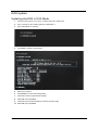
Updating the BIOS in DOS Mode . . . . . . . . . . . . . . . . . . . . . . . . . . . . . . . . . . . . .62
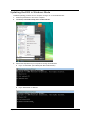
Updating the BIOS in Windows Mode . . . . . . . . . . . . . . . . . . . . . . . . . . . . . . . . .63
Clearing CMOS . . . . . . . . . . . . . . . . . . . . . . . . . . . . . . . . . . . . . . . . . . . . . . . . . . . . . .66
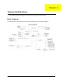
System Architecture ............................................................................. 67
Block Diagram . . . . . . . . . . . . . . . . . . . . . . . . . . . . . . . . . . . . . . . . . . . . . . . . . . . . . . .67
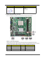
Mainboard Layout . . . . . . . . . . . . . . . . . . . . . . . . . . . . . . . . . . . . . . . . . . . . . . . . . . . .68
Jumper Setting . . . . . . . . . . . . . . . . . . . . . . . . . . . . . . . . . . . . . . . . . . . . . . . . . . . . . .69
Internal header pin definition . . . . . . . . . . . . . . . . . . . . . . . . . . . . . . . . . . . . . . . . . . . 70
Connecting Optional Devices . . . . . . . . . . . . . . . . . . . . . . . . . . . . . . . . . . . . . . . . . . 72
Connecting Case Components . . . . . . . . . . . . . . . . . . . . . . . . . . . . . . . . . . . . . . . . . . 74
Field Replaceable Unit (FRU) List ......................................................... 77
Exploded Diagram . . . . . . . . . . . . . . . . . . . . . . . . . . . . . . . . . . . . . . . . . . . . . . . . . . 77
Aspire AX1400 FRU List. . . . . . . . . . . . . . . . . . . . . . . . . . . . . . . . . . . . . . . . . . . . . . . . 78
vii
Table of Contents
Technical Specifications ....................................................................... 88
Processor . . . . . . . . . . . . . . . . . . . . . . . . . . . . . . . . . . . . . . . . . . . . . . . . . . . . . . . . . . 88
Chipsets . . . . . . . . . . . . . . . . . . . . . . . . . . . . . . . . . . . . . . . . . . . . . . . . . . . . . . . . . . .88
BIOS . . . . . . . . . . . . . . . . . . . . . . . . . . . . . . . . . . . . . . . . . . . . . . . . . . . . . . . . . . . . . . .88
Memory . . . . . . . . . . . . . . . . . . . . . . . . . . . . . . . . . . . . . . . . . . . . . . . . . . . . . . . . . . . 89
Hard Disk Drive . . . . . . . . . . . . . . . . . . . . . . . . . . . . . . . . . . . . . . . . . . . . . . . . . . . . . . 89
Optical Disc Drive . . . . . . . . . . . . . . . . . . . . . . . . . . . . . . . . . . . . . . . . . . . . . . . . . . . . 90
Card Reader (optional) . . . . . . . . . . . . . . . . . . . . . . . . . . . . . . . . . . . . . . . . . . . . . . . . 90
Gigabit Ethernet . . . . . . . . . . . . . . . . . . . . . . . . . . . . . . . . . . . . . . . . . . . . . . . . . . . . . 90
Audio . . . . . . . . . . . . . . . . . . . . . . . . . . . . . . . . . . . . . . . . . . . . . . . . . . . . . . . . . . . . . .90
Power Supply Unit . . . . . . . . . . . . . . . . . . . . . . . . . . . . . . . . . . . . . . . . . . . . . . . . . . . .91
Power Management . . . . . . . . . . . . . . . . . . . . . . . . . . . . . . . . . . . . . . . . . . . . . . . . . . 91
Index ...................................................................................................... 93
viii
Chapter 1
Features and Specifications
This chapter lists the features and specifications of the Aspire AX1400 computer.
NOTE
The items listed in this section are for reference only. The exact configuration of your PC depends
on the model purchased. Refer to the FRU list chapter on page 69 for a detailed list of models
supported by each hardware component.
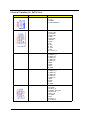
System Features
Component
Description
Operating system support
•
Microsoft Windows 7 Home Basic (X64/X86)
•
Microsoft Windows 7 Home Premium (X64/X86)
•
Microsoft Windows Starter X86
•
Microsoft Windows XP Home X86
•
Ubuntu X-windows version
•
FreeDos
•
Sockets AM2+/AM3, 941 pin contacts
•
Supports the following AMD processors:
– Phenom II 705e and 700e
– Athlon II x3 405e and 400e
– Athlon II x2 255, 250, 245, 240
– Athlon II x2 215, 240e and 235e
– Athlon II x2 B24 and B22
– Athlon II x2 260u, 250u, 160u and 150u
– Sempron 140
•
NVIDIA® nForce® 430 MCP (MCP61), or
•
NVIDIA® nForce® 730a/720a MCP (MCP78)
Processor
Chipset
Graphics controller
Integrated in the NVIDIA® nForce® Chipset
Memory
•
Two DIMM slots supporting 240-pin unbuffered DDR3 SDRAM modules
•
Data rate supported: 800/1066/1333 MT/s
•
Maximum memory: 4 GB (using two 2 GB modules)
Expansion options
Connectivity
Hard disk drive (HDD)
Optical disc drive (ODD)
Aspire AX1400 Service Guide
•
One PCI Express x16 slot (reserved for GPU card installation)
•
One PCI Express x1 slot
•
Wired LAN: Realtek RTL8201EL (Single-Chip/Port 10/100 Fast Ethernet
PHYceiver with Auto MDIX)
•
WLAN option: 802.11 b/g/n wireless network adapter
•
One HDD bay suppporting 3.5-inch 25.4 mm SATA HDDs
•
Support 7200 rpm SATA HDD in 320 - 1000 GB capacities
•
One ODD bay supporting 5.25-inch standard SATA ODD
•
Supports DVD-R/RW drive or DVD-Super Multi double-layer drive
1
Component
Description
Card reader (optional)
•
9-in-1 card reader (optional)
•
The following memory cards are supported:
– Memory Stick (MS), Memory Stick Micro (M2)
– xD-Picture Card (xD)
– Secure Digital (SD), MultiMediaCard (MMC)
– CompactFlash, Type I/II (CF, Type I and II)
– Memory Stick PRO (MS PRO)
TV tuner (optional)
AVerMedia H751 PCI-E Hybrid Analog/ATSC Card
Power supply
220 W power supply unit (non-PFC, non-power factor correction)
220 W power supply unit (PFC)
Antivirus software
Norton Internet Security
System BIOS
•
AMI BIOS with 8 MB SPI ROM
•
Supports ACPI revision 2.0 standard
•
Supports Plug and Play, STR(S3)/STD(S4), hardware monitor, Multi Boot,
and DMI protocols
•
ACPI 2.0 or 1.0b (Advanced Configuration Power Interface) standard
•
S0, S1, S2 and S5 sleep states support
Power management
•
On-board device power management support
•
On-board device configuration support
Audio
Item
Description
Audio codec
•
Realtek ALC888S 7.1+2 Channel High Definition Audio Codec, or
•
Realtek ALC662 5.1 Channel High Definition Audio Codec
•
Front panel: Headphone and microphone jacks
•
Rear panel: Microphone, line-out, and line-in jacks
Audio jacks
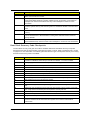
I/O Ports and LED Indicators
Component
Description
I/O ports
•
Front panel
– USB ports (five)
– Headphone jack
– Microphone jack
– CF card slot
– Memory Stick PRO card slot
•
Rear panel
– PS/2 keyboard and mouse ports
– External display (VGA) port
– USB ports (four)
– Ethernet jack (RJ45)
– Microphone, line-out, and line-in jacks
•
Hard drive activity
•
Power status
LED indicators
2
Aspire AX1400 Service Guide
Physical Specifications
Aspect
Description
Chassis dimension (W × D × H)
100 mm (W) X 367.8 mm (D) x 269 mm (H)
System weight
5.808 kg.
Mainboard form factor
microATX (µATX)
Mainboard dimensions (W × H)
244 × 220 mm
Environmental Requirements
Aspect
Description
Operating temperature
5 to 35 °C (41 to 95 °F)
Operating humidity
15% to 80% RH non-condensing
Aspire AX1400 Service Guide
3
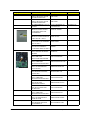
System Tour
The pictures and tables in this section illustrate the physical outlook of the computer.
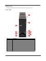
Front View
4
No.
Component
1
Power button/indicator
2
Optical drive cover
3
Optical drive button
4
XD (XD-Picture) and SD/MMC (Secure Digital/MultiMedia Card) slots
5
CF card slot (Type I and II)
6
USB 2.0 ports
7
Headphone jack
8
Microphone-in jack
9
USB 2.0 ports
10
USB 2.0 port
11
Acer logo
Aspire AX1400 Service Guide
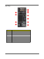
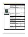
Rear View
No.
Component
1
Line-in jack
2
LAN connector
3
PS/2 mouse port
4
Power connector
5
Fan aperture
6
PS/2 keyboard port
7
Monitor port
8
USB 2.0 ports
9
Microphone jack
10
Line-out jack
11
Expansion slots
Aspire AX1400 Service Guide
5
6
Aspire AX1400 Service Guide
Chapter 2
System Utilities
CMOS Setup Utility
CMOS Setup Utility is a hardware configuration program built into the system ROM. Since most systems are
already properly configured and optimized, there is normally no need to run this utility.
You will need to run this utility under the following conditions:
•
When changing the system configuration including:
•
Setting the system time and date
•
Configuring the system drives and peripherals
•
Specifying the boot device sequence
•
Configuring the power management modes
•
Setting up system passwords or making other changes to the security setup
•
When trying to resolve IRQ conflicts
•
When a configuration error is detected by the system and you are prompted ("Run Setup" message) to
make changes to the BIOS settings.
The Setup Utility loads the configuration values in a battery-backed nonvolatile memory called CMOS RAM.
This memory area is not part of the system RAM, which allows configuration data to be retained when power is
turned off. The values take effect when the system is booted. POST uses these values to configure the
hardware. If the values and the actual hardware do not agree, POST generates an error message. You must
run this utility to change the hardware settings from the default or current configuration.
IMPORTANT
NOTE
If you repeatedly receive “Run Setup” messages, the RTC battery located on the mainboard
(BT1) may be defective. In this case, the system cannot retain configuration values in CMOS.
Replace the RTC battery with a new one.
For ease of reading, CMOS Setup Utility will be simply referred to as “Setup” or “Setup Utility” in this
Service Guide.
Aspire AX1400 Service Guide
7
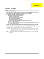
Accessing the Setup Utility
1.
Turn on the computer.
If the computer is already turned on, save your data and close all open applications, then restart the
computer.
2.
During POST, press Delete.
If you fail to press Delete before POST is completed, you will need to restart the computer.
Use the Up/Down/Left/Right arrow keys to move between the menu options, then press Enter to execute that
option.
Some options lead to pop-up dialog boxes that prompt you to verify that you wish to execute that option. Other
options lead to dialog boxes that prompt you for information.
Some options (marked with a ) lead to submenus that enable you to change the values for the option. Use
the Up/Down/Left/Right arrow keys to scroll through the items in the submenu
8
Aspire AX1400 Service Guide
Navigating through the Setup Utility
Use the keys listed in the legend bar on the bottom of the Setup screen to work your way through the various
menu and submenu screens of the Setup Utility. The table below lists these legend keys and their respective
functions.
Key
Function
Up/Down/Left/
Right arrow keys
Move the cursor to the menu/field you want.The currently selected field will be highlighted.
Enter
•
To open the page for the currently selected menu/submenu
•
To apply a field value.
PgUp and PgDn
Move the cursor to the previous and next page of a multipage menu.
Home
Move the cursor to the first page of a multipage menu.
End
Move the cursor to the last page of a multipage menu.
+ and -
To select a value for the currently selected field (only if it is user-configurable). Press these
keys repeatedly to display all possible entries. A parameter that is enclosed in square
brackets [ ] is user-configurable. Grayed-out parameters are not user-configurable for one
of the following reasons:
Esc
•
The field value is auto-configured or auto-detected.·
•
The field value is informational only.
•
The field is password-protected.
If you press this key:
•
On one of the primary menu screens, the Exit menu displays.
•
On a submenu screen, the previous screen displays.
•
When you are making selections from a pop-up menu, closes the pop-up without making
a selection.
F1
To bring up the General Help window. The General Help window describes other Setup
navigation keys that are not displayed on the legend bar.
F9
Press to load default system values.
F10
Press to save changes and close the Setup Utility.
Setup Utility Menus
The Setup Utility has twelve menus for configuring the various system functions. These include:
• Product Information
• PC Health Status
• Standard CMOS Features
• Frequency/Voltage Control
• Advanced BIOS Features
• BIOS Security Features
• Advanced Chipset Features
• Load Default Settings
• Integrated Peripherals
• Save & Exit Setup
• Power Management Setup
• Exit Without Saving
NOTES
• The screenshots used in this section are for illustration only. The values displayed may not be
the same as those in your computer.
• In the descriptive tables following each of the menu screen illustrations, settings in boldface are
the default and suggested settings.
Aspire AX1400 Service Guide
9
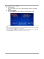
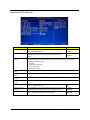
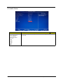
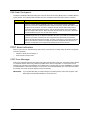
Product Information
The Product Information menu displays basic information about the system. These entries are for your
reference only and are not user-configurable.
10
Field
Description
Processor Type
Type of processor installed on the system
Processor Speed
Speed of the processor installed on the system
System Memory
Size of system memory detected during boot-up
Product Name
Official model name of the computer.
System Serial Number
System serial number.
System BIOS Version
Current system BIOS version
BIOS Release Date
Date when the CMOS setup utility was released.
Asset Tag Number
System asset tag number
Aspire AX1400 Service Guide
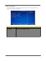
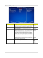
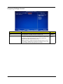
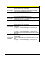
Standard CMOS Features
Field
Description
Value
System Date
Sets the system date.
MM/DD/YYYY
(month/day/year)
System Time
Sets the system time.
HH:MM:SS
(hour:minute:second)
SATA Port 1–2
Your Aspire computer supports two SATA channels, each channel allows one SATA device to
be installed. Press Enter to display the individual configuration screen of installed SATA
drive(s).
Halt On
Determines whether the system will stop for an error during the
POST. Options include:
• All Errors - Any error detected will pause the system.
• No Errors - BIOS will ignore any errors detected during POST
• All, but Keyboard - If a keyboard error is detected, BIOS will
pause the system.
Aspire AX1400 Service Guide
All Errors
No Errors
All, But Keyboard
11
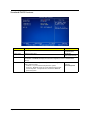
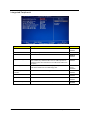
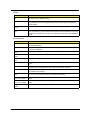
Advanced BIOS Features
12
Field
Description
Value
Quick Boot
When enabled, the system starts up more quickly be elimination
some of the POST routines.
Enabled
Disabled
Quiet Boot
When enabled, BIOS will show a full screen logo when booting; if
disabled, BIOS will show the diagnostic POST screen when
booting.
Enabled
Disabled
1st/2nd/3rd/4th Boot
Device
Displays the device assigned to the specified boot sequence. The Setup Utility attempts to
boot the operating system in this order. By default, the computer searches for boot
devices in the following order:
• Hard disk
• Optical drive (CD/DVD)
• Removable device
• Network boot (LAN)
Hard Disk Drive
Priority
Press Enter to specify the boot device priority sequence for the installed hard drive(s).
Optical Disk Drive
Priority
Press Enter to specify the boot device priority sequence for the installed optical drive.
Removable Device
Priority
Press Enter to specify the boot device priority sequence for removable drives.
Network Device
Priority
Press Enter to specify the boot device priority sequence foe available network drives.
Bootup Num-Lock
If you set this item to On, the keyboard Num Lock key will be active
when the computer boots up.
On
Off
Boot Sector Virus
Protection
If set to Disabled, when anything attempts to access the boot sector
or hard disk partition table, there will be no warning message.
Enabled
Disabled
USB Beep Message
Select whether to allow the BIOS to emit error beeps or display
error messages during USB device enumeration.
Enabled
Disabled
Aspire AX1400 Service Guide
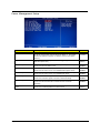
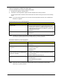
Advanced Chipset Features
Field
Description
Value
AMD Cool ’n’ Quiet
Select whether to enable the AMD Cool 'N' Quiet Technology. This
technology allows a compliant OS to dynamically adjust the system
voltage and core frequency for reduced heat and noise emission.
Enabled
Disabled
AMD-V
Select whether to enable the AMD-V Technology. This technology
allows a single platform to run multiple operating systems in
independent partitions.
Enabled
Disabled
Memory Hole Remapping
When enabled, some or all of the memory between the 2 GB and
4 GB limits to addresses above 4 GB. This is a workaround for the
PCI hole or PCI memory hole which is a limitation of 32-bit
hardware and 32-bit operating systems that causes a computer to
appear to have less memory available than is physically installed.
Note: This feature is useful for systems running on 64-bit OS and
those 32-bit systems that support the Physical Address Extension
method.
Enabled
Disabled
Primary Video
When a GPU expansion board is installed, you have the option to
select which graphics controller to activate.
Note: When this field is set to Auto, the graphics controller priority
sequence is: PCIE, Onboard, then PCI.
Auto
PCIE
Onboard
PCI
UMA Frame Buffer Size
When a GPU expansion board is installed, you can select how the
system video memory (frame buffer) is allotted.
Auto
32 MB
64 MB
128 MB
256 MB
Aspire AX1400 Service Guide
13
Integrated Peripherals
14
Field
Description
Value
Onboard SATA Controller
Enables or disables the onboard SATA controller.
Enabled
Disabled
Onboard SATA Mode
Set the operating mode for the onboard SATA controller.
Native IDE
Onboard USB Controller
Enables or disables the onboard USB controller.
Legacy USB Support
Enables or disables support for a USB mouse and USB keyboard.
When enabled, any attached USB mouse or USB keyboard can
control the system even when there is no USB driver loaded onto
the system.
Enabled
Disabled
USB Storage Emulation
If set to Auto, a USB devices with a capacity of equal or less than
2 GB will be emulated as a bootable floppy disk.
Auto
Floppy
Hard Disk
Onboard Graphics
Controller
Enables or disables the onboard graphics controller.
Enabled
Disabled
Onboard Audio Controller
Enables or disables the onboard audio controller.
Enabled
Disabled
Onboard LAN Controller
Enables or disables the onboard LAN controller.
Enabled
Disabled
Onboard LAN Option ROM
Enables or disables the onboard LAN option ROM function.
Enabled
Disabled
Enabled
Disabled
Aspire AX1400 Service Guide
Power Management Setup
Field
Description
Value
ACPI Suspend Mode
Use this item to define how your system suspends. Default value is
S3 (STR), the suspend mode is suspend to RAM, i.e., the system
shuts down with the exception of a refresh current to the system
memory.
S3 (STR)
S1 (POS)
Deep Power Off Mode
Enables or disables compliance to the Energy-using Products Lot 6
Directives (EuP Lot 6).
Enabled
Disabled
Power On by RTC Alarm
Enables or disables the system to wake up from a power-saving
mode when an RTC alarm occurs.
Enabled
Disabled
Power On by PCIE Devices
Enables or disables the system to wake up from a power-saving
mode when an event occurs on an installed PCI Express device.
Enabled
Disabled
Power On by PCI Devices
Enables or disables the system to wake up from a power-saving
mode when an event occurs on an installed PCI device.
Enabled
Disabled
Power On by Modem Ring
Enables or disables the system to wake up from a power-saving
mode when a modem signal is received. network message
Enabled
Disabled
Power On by Onboard LAN
Enables or disables the system to wake up from a power-saving
mode when the onboard LAN controller received a network
message.
Enabled
Disabled
Wake Up by PS/2 KB/
Mouse
Enables or disables the system to wake up from a power-saving
mode when a PS/2 keyboard or mouse is used.
Enabled
Disabled
Aspire AX1400 Service Guide
15
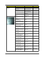
PC Health Status
16
Field
Description
Value
CPU Temperature
System Temperature
CPU Fan Speed
System Fan Speed
CPU Core
+1.2V
+3.30V
+5.00V
+12.0V
5VSB
VBAT
These items lets you monitor the parameters for critical voltages, temperatures and
fan speeds.
Aspire AX1400 Service Guide
Frequency/Voltage Control
Field
Description
Value
Enable Clock to All DIMM/
PCI
When enabled, clock signals will be sent to the PCI and memory
slots regardless of whether the slot is occupied or not.
Enabled
Disabled
Spread Spectrum
When the mainboard's clock generator pulses, the extreme values of
the pulses creates EMI (electromagnetic interference). Set this field
to Enabled to reduce this EMI level. This reduces interference
problems with other electronics in the area.
Note: Remember to disable the Spread Spectrum feature if you are
overclocking. A slight jitter can introduce a temporary boost in clock
speed causing the overclocked processor to lock up.
Enabled
Disabled
Aspire AX1400 Service Guide
17
BIOS Security Features
Field
Description
Supervisor Password
Displays the supervisor password status. When set to Installed, this password will
allow the user to access and change all settings in the Setup Utility.
User Password
Displays the user password status. Only the following menus will be accessible
when this password is set as Installed:
• System Date and System Time
• Exit Without Saving
Change Supervisor
Password
Press Enter to change the supervisor password.
Setting a system password
Note the following before you define a system password:
18
•
The maximum length of password contains 8 alphanumeric characters—A - Z, 0 - 9, and ‘;’
(for French keyboard).
•
System passwords are case-insensitive.
•
When you are prompted to enter a password, you have three tries before the system halts. Do not forget
your password. If you forget your password, you may have to return your computer to your dealer to reset
it.
Aspire AX1400 Service Guide
To set a system password:
NOTE
1.
You need to set a supervisor password first before setting the user password.
Select Change Supervisor Password or Change User Password, then press Enter.
The password box appears.
2.
Type a password then press Enter.
IMPORTANT
3.
Be very careful when typing your password because the characters do not appear on the
screen. Only shaded blocks representing each typed character are visible.
Retype the password to verify the first entry, then press Enter.
You will be prompted to save the new password.
4.
Press Enter.
5.
Press F10 to save the password and close the Setup Utility.
To change a system password:
1.
Select Change Supervisor Password or Change User Password, then press Enter.
The password box appears.
2.
Type the original password, then press Enter.
3.
Type a new password, then press Enter.
4.
Retype the new password to verify the first entry, then press Enter.
You will be prompted to save the new password.
5.
Press Enter.
6.
Press F10 to save the password and close the Setup Utility.
To remove a system password:
NOTE
1.
When the supervisor password is removed, the user password will also be remove.
Select Change Supervisor Password or Change User Password, then press Enter.
The password box appears.
2.
Type the original password, then press Enter.
3.
Press Enter twice without entering anything in the new and confirm password fields.
You will be prompted to confirm the password removal.
4.
Press Enter.
5.
Press F10 to save the changes you made and close the Setup Utility.
Aspire AX1400 Service Guide
19
Load Default Settings
Execute this menu to load the factory-default settings for all Setup parameters. Keyboard shortcut: F9
Perform the steps below to load the system default settings:
1.
Select Load Default Settings, then press Enter.
You will be prompted to load the system defaults.
2.
Select OK, then press Enter.
3.
Press F10 to save the changes you made and close the Setup Utility.
Save & Exit Setup
Execute this menu to save the changes made and closes the Setup Utility. Keyboard shortcut: F10
20
Aspire AX1400 Service Guide
Exit Without Saving
Execute this menu to closes the Setup Utility without making any changes.
Aspire AX1400 Service Guide
21
22
Aspire AX1400 Service Guide
Chapter 3
System Disassembly
This chapter provides step-by-step instructions on how to disassemble the computer for maintenance and
troubleshooting purposes.
Disassembly Tools
In performing the disassembly process, you will need the following tools:
•
Wrist-grounding strap and conductive mat for preventing electrostatic discharge
•
Philips screwdriver
•
Flat screwdriver
NOTES
• To reinstall the system components and assemble the unit, perform the disassembly procedures in
reverse.
• The screws for the different components vary in size. During the disassembly process, group the
screws with their corresponding components to avoid mismatches when putting back the
components.
Pre-disassembly Procedure
Before proceeding with the disassembly procedure, perform the steps listed below:
1.
Make sure that the optical disc drive and the optional card reader slots are empty.
2.
Turn off the power to the computer and all peripherals.
3.
Unplug the power cord from the computer.
4.
Unplug the network cable and all connected peripheral devices from the computer.
5.
Place the computer on a flat, steady surface.
Aspire AX1400 Service Guide
23
Disassembly Procedures
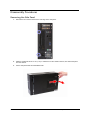
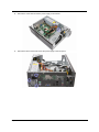
Removing the Side Panel
24
1.
Remove the two screws located on the rear edge of the side panel.
2.
Slide the panel back about 2.5 cm (1.0 in) to release it from the chassis notches, then detach the panel
from the chassis.
3.
Put the side panel aside for reinstallation later.
Aspire AX1400 Service Guide
Removing the Front Bezel
1.
Release the front bezel retention tabs from the chassis interior.
2.
Pull the front bezel away from the chassis.
NOTE: The power switch and LED cable from the front bezel is still connected to its connector on the
mainboard. To detach the front bezel completely, you have to remove the hard disk and optical drive.
Aspire AX1400 Service Guide
25
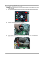
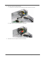
Removing the Heat Sink Fan Assembly
WARNING:The heat sink becomes very hot when the system is on. NEVER touch the heat sink with any metal
or with your hands.
26
1.
Use a long-nosed screwdriver to loosen the four screws on the heat sink, in the order as shown below.
2.
Lift the heat sink fan assembly away from the mainboard.
3.
Lay down the heat sink fan assembly, in an upright position, on top of the optical drive, as shown below,
then disconnect the fan cable from the mainboard.
Aspire AX1400 Service Guide
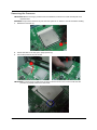
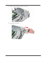
Removing the Processor
IMPORTANT:IBefore removing a processor from the mainboard, make sure to create a backup file of all
important data.
WARNING:The processor becomes very hot when the system is on. Allow it to cool off first before handling.
1.
Release the load lever (1).
2.
Pull the load lever to the fully open, upright position (2).
3.
Pull out the processor from the socket.
IMPORTANT:If you are going to install a new processor, note the arrow on the corner to make sure the
processor is properly oriented over the socket.
Aspire AX1400 Service Guide
27
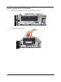
Removing the HDD-ODD Bracket
28
1.
Remove the two screws that secure the HDD-ODD bracket to the chassis.
2.
Lift the bracket up and turn it over.
Aspire AX1400 Service Guide
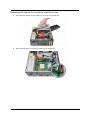
Removing the Optical Drive and the Hard Disk Drive
1.
Disconnect the SATA and power cables from the rear of the optical drive.
2.
Disconnect the other end of the SATA cable from the mainboard.
Aspire AX1400 Service Guide
29
30
3.
Disconnect the SATA and power cables from the rear of the hard disk drive.
4.
Disconnect the other end of the SATA cable from the mainboard.
Aspire AX1400 Service Guide
5.
Remove the screws that secure the optical drive to the HDD-ODD bracket.
6.
Pull the optical drive out of the drive bay.
Aspire AX1400 Service Guide
31
32
7.
Remove the four screws that secure the hard disk drive to the HDD bracket.
8.
Slide the hard disk drive out of the bracket.
Aspire AX1400 Service Guide
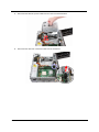
Removing the Front Bezel
1.
Disconnect the power button/LED cable from its mainboard connector.
2.
Pull out the power button/LED cable from the chassis.
3.
Detach the front bezel.
Aspire AX1400 Service Guide
33
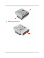
Removing the Expansion Boards
34
1.
Remove the screw from the expansion board bracket opposite the PCIEX2 slot.
2.
Gently pull up the expansion board to remove it from the mainboard.
Aspire AX1400 Service Guide
3.
Remove the screw from the expansion board bracket opposite the PCI_1 slot.
4.
Gently pull up the expansion board to remove it from the mainboard.
Aspire AX1400 Service Guide
35
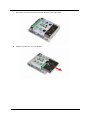
Removing the Memory Modules
1.
Open the holding clips (a) securing the memory modules.
2.
Gently pull the DIMM upward to pull it away from the chassis (b).
Removing the Power Supply Unit
1.
36
Disconnect the 4-pin and the 24-pin ATX power supply cables from its mainboard connector.
a.
Squeeze on the retaining latch (a) attached to the cable end of the connector.
b.
Grasp the cable end of the connector and pull it straight up (b).
Aspire AX1400 Service Guide
2.
Remove the screw that secures the power supply to the chassis.
3.
Remove the three screws that secure the power supply to the rear panel.
Aspire AX1400 Service Guide
37
4.
Lift the power supply module out of the chassis.
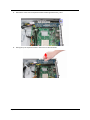
Removing the Front I/O and Optional Card Reader Assemblies
1.
38
Disconnect the front I/O and optional card reader cables from their mainboard connectors.
Aspire AX1400 Service Guide
2.
Pull up the plastic clips to release the cables.
Aspire AX1400 Service Guide
39
3.
4.
40
Remove the optional card reader assembly.
a.
Remove the two screws that secure the optional card reader assembly to the bracket.
b.
Pull the optional card reader assembly out of the bracket.
Remove the front I/O and optional card reader board bracket.
Aspire AX1400 Service Guide
a.
Remove the screw that secures the bracket to the chassis.
b.
Pull the bracket out the chassis.
Aspire AX1400 Service Guide
41
5.
42
Remove the front I/O assembly.
a.
Remove the two screws that secure the front I/O assembly to the bracket.
b.
Remove front I/O assembly from the bracket.
Aspire AX1400 Service Guide
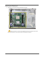
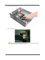
Removing the Mainboard
1.
Remove the four screws that secure the mainboard to the chassis.
Note:Circuit boards >10 cm2 has been highlighted with the yellow rectangle as above image
shows. Please detach the Circuit boards and follow local regulations for disposal.
Aspire AX1400 Service Guide
43
2.
Lift the board from the chassis.
3.
Remove the RTC battery.
Note:RTC battery has been highlighted with the yellow circle as above image shows. Please
detach the RTC battery and follow local regulations for disposal.
44
Aspire AX1400 Service Guide
Chapter 4
Troubleshooting
This chapter lists the POST error indicators and BIOS beep codes, as well general troubleshooting
instructions.
Hardware Diagnostic Procedure
1.
Obtain as much detail as possible about the symptoms of the system failure.
2.
Verify the symptoms by attempting to recreate the failure by running the diagnostic tests or repeating the
same operation.
3.
Refer to “Power System Check” procedure on the next section and the “Beep Codes” section on page 60
to determine which corrective action to take.
System Check Procedures
IMPORTANT
The diagnostic tests described in this chapter are only intended to test Acer products.
Non-Acer products, prototype cards, or modified options can give false errors and invalid
system responses.
Power System Check
If the system can be powered on, skip this section. Proceed to the “System Internal Inspection” procedure on
the next page.
If the system will not power on, do the following:
•
Check if the power cable is properly connected to the AC power jack and a functional AC power source.
•
Check if the voltage selector switch is set to the correct voltage setting.
System External Inspection
1.
Inspect the power and LED indicators on the front panel. Go to “Front View” section on page 4 for the
location and description of the LED behaviour.
2.
3.
Make sure that the ventilation slots on the rear panel are not blocked.
Make sure that there is no point of contact in the system that can cause a power short.
If the cause of the failure is still can not be determined, perform the “System Internal Inspection”
procedure described on the next page.
Aspire AX1400 Service Guide
45
System Internal Inspection
1.
Turn off the power to the computer and all peripherals.
2.
Unplug the power cord from the computer.
3.
Unplug the network cable and all connected peripheral devices from the computer.
4.
5.
6.
7.
8.
Place the computer on a flat, steady surface.
Remove the side panel as described in page 24.
Verify that the processor, memory module(s), and expansion board(s) are properly seated.
Verify that all power and data cables are firmly and properly attached to the installed drives.
Verify that all cable connections inside the system are firmly and properly attached to their appropriate
mainboard connectors.
9. Verify that all components are Acer-qualified and supported.
10. Reinstall the side panel.
11. Power on the system.
If the cause of the failure is still can not be determined, review the POST messages and BIOS
checkpoints during the system startup.
Checkpoints
A checkpoint is either a byte or word value output to I/O port 80h. The BIOS outputs checkpoints during
bootblock and Power-On Self Test (POST) to indicate the task the system is currently executing. Checkpoints
are very useful in aiding software developers or technicians in debugging problems that occur during the
pre-boot process.
Viewing BIOS Checkpoints
Viewing all checkpoints generated by the BIOS requires a checkpoint card, also referred to as a POST card or
POST diagnostic card. These are ISA or PCI add-in cards that show the value of I/O port 80h on a LED
display. Checkpoints may appear on the bottom right corner of the screen during POST. This display method is
limited, since it only displays checkpoints that occur after the video card has been activated.
NOTE
Please note that checkpoints may differ between different platforms based on system
configuration. Checkpoints may change due to vendor requirements, system chipset or option
ROMs from add-in PCI devices.
Boot Block Initialization Code Checkpoints
The boot block initialization code sets up the chipset, memory, and other components before system memory
is available. The following table describes the type of checkpoints that may occur during the boot block
initialization portion of the BIOS.
46
Checkpoint
Description
Before D1
Early chipset initialization is done. Early super I/O initialization is done including RTC and
keyboard controller. NMI is disabled.
D1
Perform keyboard controller BAT test. Check if waking up from power management
suspend state. Save power-on CPUID value in scratch CMOS.
D0
Go to flat mode with 4GB limit and GA20 enabled. Verify the bootblock checksum.
D2
Disable CACHE before memory detection. Execute full memory sizing module. Verify that
flat mode is enabled.
D3
If memory sizing module not executed, start memory refresh and do memory sizing in
bootblock code. Do additional chipset initialization. Re-enable CACHE. Verify that flat
mode is enabled.
D4
Test base 512 KB memory. Adjust policies and cache first 8 MB. Set stack.
Aspire AX1400 Service Guide
Checkpoint
Description
D5
Bootblock code is copied from ROM to lower system memory and control is given to it.
BIOS now executes out of RAM.
D6
Both key sequence and OEM specific method is checked to determine if BIOS recovery is
forced. Main BIOS checksum is tested. If BIOS recovery is necessary, control flows to
checkpoint E0. See the “Boot Block Recovery Code Checkpoints” section for more
information.
D7
Restore CPUID value back into register. The Bootblock Runtime interface module is
moved to system memory and control is given to it. Determine whether to execute serial
flash.
D8
The Runtime module is uncompressed into memory. CPUID information is stored in
memory.
D9
Store the Uncompressed pointer for future use in PMM. Copying Main BIOS into memory.
Leaves all RAM below 1 MB Read-Write including E000 and F000 shadow areas but
closing SMRAM.
DA
Restore CPUID value back into register. Give control to BIOS POST
(ExecutePOSTKernel). See the “POST Code Checkpoints” section for more information.
Boot Block Recovery Code Checkpoints
The boot block recovery code gets control when the BIOS determines that a BIOS recovery is required
because the user has forced the update or the BIOS checksum is corrupt. Refer to “BIOS Recovery” section
on page 61 for more information. The following table describes the type of checkpoints that may occur during
the boot block recovery portion of the BIOS.
Checkpoint
Description
E0
Initialize the floppy controller in the super I/O. Some interrupt vectors are initialized. DMA
controller is initialized. 8259 interrupt controller is initialized. L1 cache is enabled.
E9
Set up floppy controller and data. Attempt to read from floppy.
EA
Enable ATAPI hardware. Attempt to read from ARMD and ATAPI CDROM.
EB
Disable ATAPI hardware. Jump back to checkpoint E9.
EF
Read error occurred on media. Jump back to checkpoint EB.
E9 or EA
Determine information about root directory of recovery media.
F0
Search for pre-defined recovery file name in root directory.
F1
Recovery file not found.
F2
Start reading FAT table and analyze FAT to find the clusters occupied by the recovery file.
F3
Start reading the recovery file cluster by cluster.
F5
Disable L1 cache.
FA
Check the validity of the recovery file configuration to the current configuration of the flash
part.
FB
Make flash write enabled through chipset and OEM specific method. Detect proper flash
part. Verify that the found flash part size equals the recovery file size.
F4
The recovery file size does not equal the found flash part size.
FC
Erase the flash part.
FD
Program the flash part.
FF
The flash has been updated successfully. Make flash write disabled. Disable ATAPI
hardware. Restore CPUID value back into register. Give control to F000 ROM at
F000:FFF0h.
Aspire AX1400 Service Guide
47
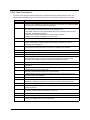
POST Code Checkpoints
The POST code checkpoints are the largest set of checkpoints during the BIOS preboot process. The
following table describes the type of checkpoints that may occur during the POST portion of the BIOS.
48
Checkpoint
Description
03
Disable NMI, Parity, video for EGA, and DMA controllers. Initialize BIOS, POST, Runtime
data area. Also initialize BIOS modules on POST entry and GPNV area. Initialized CMOS
as mentioned in the Kernel Variable "wCMOSFlags."
04
Check CMOS diagnostic byte to determine if battery power is OK and CMOS checksum is
OK. Verify CMOS checksum manually by reading storage area.
If the CMOS checksum is bad, update CMOS with power-on default values and clear
passwords. Initialize status register A.
Initializes data variables that are based on CMOS setup questions.
Initializes both the 8259 compatible PICs in the system
05
Initializes the interrupt controlling hardware (generally PIC) and interrupt vector table.
06
Do R/W test to CH-2 count reg. Initialize CH-0 as system timer.Install the POSTINT1Ch
handler. Enable IRQ-0 in PIC for system timer interrupt. Traps INT1Ch vector to
"POSTINT1ChHandlerBlock."
08
Initializes the CPU. The BAT test is being done on KBC. Program the keyboard controller
command byte is being done after Auto detection of KB/MS using AMI KB-5.
0A
Initializes the 8042 compatible Key Board Controller.
0B
Detects the presence of PS/2 mouse.
0C
Detects the presence of Keyboard in KBC port.
0E
Testing and initialization of different Input Devices. Also, update the Kernel Variables.
Traps the INT09h vector, so that the POST INT09h handler gets control for IRQ1.
Uncompress all available language, BIOS logo, and Silent logo modules.
13
Early POST initialization of chipset registers.
24
Uncompress and initialize any platform specific BIOS modules. GPNV is initialized at this
checkpoint.
30
Initialize System Management Interrupt.
2A
Initializes different devices through DIM.
See DIM Code Checkpoints section for more information.
2C
Initializes different devices. Detects and initializes the video adapter installed in the
system that have optional ROMs.
2E
Initializes all the output devices.
31
Allocate memory for ADM module and uncompress it. Give control to ADM module for
initialization. Initialize language and font modules for ADM. Activate ADM module.
33
Initializes the silent boot module. Set the window for displaying text information.
37
Displaying sign-on message, CPU information, setup key message, and any OEM
specific information.
38
Initializes different devices through DIM. See DIM Code Checkpoints section for more
information. USB controllers are initialized at this point.
39
Initializes DMAC-1 & DMAC-2.
3A
Initialize RTC date/time.
3B
Test for total memory installed in the system. Also, Check for DEL or ESC keys to limit
memory test. Display total memory in the system.
Aspire AX1400 Service Guide
Checkpoint
Description
3C
Mid POST initialization of chipset registers.
40
Detect different devices (Parallel ports, serial ports, and coprocessor in CPU, ... etc.)
successfully installed in the system and update the BDA, EBDA…etc.
50
Programming the memory hole or any kind of implementation that needs an adjustment in
system RAM size if needed.
52
Updates CMOS memory size from memory found in memory test. Allocates memory for
Extended BIOS Data Area from base memory. Programming the memory hole or any kind
of implementation that needs an adjustment in system RAM size if needed.
60
Initializes Num-Lock status and programs the KBD typematic rate.
75
Initialize Int-13 and prepare for IPL detection.
78
Initializes IPL devices controlled by BIOS and option ROMs.
7A
Initializes remaining option ROMs.
7C
Generate and write contents of ESCD in NVRam.
84
Log errors encountered during POST.
85
Display errors to the user and gets the user response for error.
87
Execute BIOS setup if needed / requested. Check boot password if installed.
8C
Late POST initialization of chipset registers.
8E
Program the peripheral parameters. Enable/Disable NMI as selected.
90
Late POST initialization of system management interrupt.
A0
Check boot password if installed.
A1
Clean-up work needed before booting to OS.
A2
Takes care of runtime image preparation for different BIOS modules. Fill the free area in
F000h segment with 0FFh. Initializes the Microsoft IRQ Routing Table. Prepares the
runtime language module. Disables the system configuration display if needed.
A4
Initialize runtime language module. Display boot option popup menu.
A7
Displays the system configuration screen if enabled. Initialize the CPU’s before boot,
which includes the programming of the MTRR’s.
A8
Prepare CPU for OS boot including final MTRR values.
A9
Wait for user input at config display if needed.
AA
Uninstall POST INT1Ch vector and INT09h vector. Deinitializes the ADM module.
AB
Prepare BBS for Int 19 boot.
AC
End of POST initialization of chipset registers.
B1
Save system context for ACPI.
00
Passes control to OS Loader (typically INT19h).
Aspire AX1400 Service Guide
49
DIM Code Checkpoints
The Device Initialization Manager (DIM) gets control at various times during BIOS POST to initialize different
system busses. The following table describes the main checkpoints where the DIM module is accessed.
Checkpoint
Description
2A
Initialize different buses and perform the following functions: Reset, Detect, and Disable
(function 0); Static Device Initialization (function 1); Boot Output Device Initialization
(function 2). Function 0 disables all device nodes, PCI devices, and PnP ISA cards. It also
assigns PCI bus numbers. Function 1 initializes all static devices that include manual
configured onboard peripherals, memory and I/O decode windows in PCI-PCI bridges,
and noncompliant PCI devices. Static resources are also reserved. Function 2 searches
for and initializes any PnP, PCI, or AGP video devices.
38
Initialize different buses and perform the following functions: Boot Input Device
Initialization (function 3); IPL Device Initialization (function 4); General Device Initialization
(function 5). Function 3 searches for and configures PCI input devices and detects if
system has standard keyboard controller. Function 4 searches for and configures all PnP
and PCI boot devices. Function 5 configures all onboard peripherals that are set to an
automatic configuration and configures all remaining PnP and PCI devices.
POST Error Indicators
When a system error is detected during POST (Power On Self Text), the Setup utility will switch to diagnostic
mode and will either:
•
Displays a POST error message, or
•
Emits a series of beep codes
POST Error Messages
POST error messages tell users what failure the system has detected. Some error messages could be related
to a hardware device. Others may indicate a problem with a device configuration. In some cases an error
message may include recommendations for troubleshooting or require that you press the Enter key to display
recommendations. Follow the instructions on the screen. It is recommended that you correct the error before
proceeding, even if the computer appears to boot successfully.
IMPORTANT
50
If your system fails after you make changes in the Setup menus, reboot the computer, enter
Setup again and load Setup defaults to correct the error.
Aspire AX1400 Service Guide
Memory
Message
Description
Gate20 Error
The BIOS is unable to properly control the mainboard’s Gate A20 function, which
controls access of memory over 1 MB. This may indicate a problem with the
mainboard.
Multi-Bit ECC Error
This message will only occur on systems using ECC enabled memory modules.
ECC memory has the ability to correct single-bit errors that may occur from faulty
memory modules.
A multiple bit corruption of memory has occurred, and the ECC memory algorithm
cannot correct it. This may indicate a defective memory module.
Parity Error
Fatal Memory Parity Error. System halts after displaying this message.
RAM R/W test failed
This message is displayed by the AMIBIOS8 when the RAM read/write test fails.
CMOS Memory Size
Wrong
The base memory (memory below 1MB) size that is reported in the CMOS (offset
15h) mismatches with the actual size detected. This condition may occur when the
hole is set at 512K base memory or when CMOS is corrupted.
Boot
Message
Description
Boot Failure...
This is a generic message indicating the BIOS could not boot from a particular
device. This message is usually followed by other information concerning the
device.
Invalid Boot Diskette
A diskette was found in the drive, but it is not configured as a bootable diskette.
Drive Not Ready
The BIOS was unable to access the drive because it indicated it was not ready for
data transfer. This is often reported by drives when no media is present.
A: Drive Error
The BIOS attempted to configure the A: drive during POST, but was unable to
properly configure the device. This may be due to a bad cable or faulty diskette
drive.
B: Drive Error
The BIOS attempted to configure the B: drive during POST, but was unable to
properly configure the device. This may be due to a bad cable or faulty diskette
drive.
Insert BOOT diskette
in A:
The BIOS attempted to boot from the A: drive, but could not find a proper boot
diskette.
Reboot and Select proper Boot device or Insert Boot Media in selected Boot device
BIOS could not find a bootable device in the system and/or removable media drive
does not contain media.
Reboot and select
proper boot device or
Insert boot media in
selected boot device
BIOS could not find a bootable device in the system and/or removable
media drive does not contain media.
NO ROM BASIC
This message occurs on some systems when no bootable device can be detected.
Aspire AX1400 Service Guide
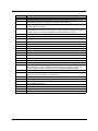
51
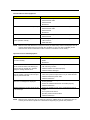
Storage Device
52
Message
Description
Primary Master Hard
Disk Error
The IDE/ATAPI device configured as Primary Master could not be properly
initialized by the BIOS. This message is typically displayed when the BIOS is trying
to detect and configure IDE/ATAPI devices in POST.
Primary Slave Hard
Disk Error
The IDE/ATAPI device configured as Primary Slave could not be properly initialized
by the BIOS. This message is typically displayed when the BIOS is trying to detect
and configure IDE/ATAPI devices in POST.
Secondary Master
Hard Disk Error
The IDE/ATAPI device configured as Secondary Master could not be properly
initialized by the BIOS. This message is typically displayed when the BIOS is trying
to detect and configure IDE/ATAPI devices in POST.
Secondary Slave
Hard Disk Error
The IDE/ATAPI device configured as Secondary Slave could not be properly
initialized by the BIOS. This message is typically displayed when the BIOS is trying
to detect and configure IDE/ATAPI devices in POST.
3rd Master Hard Disk
Error
The IDE/ATAPI device configured as Master in the 3rd IDE controller could not be
properly initialized by the BIOS. This message is typically displayed when the BIOS
is trying to detect and configure IDE/ATAPI devices in POST.
3rd Slave Hard Disk
Error
The IDE/ATAPI device configured as Slave in the 3rd IDE controller could not be
properly initialized by the BIOS. This message is typically displayed when the BIOS
is trying to detect and configure IDE/ATAPI devices in POST.
4th Master Hard Disk
Error
The IDE/ATAPI device configured as Master in the 4th IDE controller could not be
properly initialized by the BIOS. This message is typically displayed when the BIOS
is trying to detect and configure IDE/ATAPI devices in POST.
4th Slave Hard Disk
Error
The IDE/ATAPI device configured as Slave in the 4th IDE controller could not be
properly initialized by the BIOS. This message is typically displayed when the BIOS
is trying to detect and configure IDE/ATAPI devices in POST.
5th Master Hard Disk
Error
The IDE/ATAPI device configured as Master in the 5th IDE controller could not be
properly initialized by the BIOS. This message is typically displayed when the BIOS
is trying to detect and configure IDE/ATAPI devices in POST.
5th Slave Hard Disk
Error
The IDE/ATAPI device configured as Slave in the 5th IDE controller could not be
properly initialized by the BIOS. This message is typically displayed when the BIOS
is trying to detect and configure IDE/ATAPI devices in POST.
6th Master Hard Disk
Error
The IDE/ATAPI device configured as Master in the 6th IDE controller could not be
properly initialized by the BIOS. This message is typically displayed when the BIOS
is trying to detect and configure IDE/ATAPI devices in POST.
6th Slave Hard Disk
Error
The IDE/ATAPI device configured as Slave in the 6th IDE controller could not be
properly initialized by the BIOS. This message is typically displayed when the BIOS
is trying to detect and configure IDE/ATAPI devices in POST.
Primary Master Drive
- ATAPI Incompatible
The IDE/ATAPI device configured as Primary Master failed an ATAPI compatibility
test. This message is typically displayed when the BIOS is trying to detect and
configure IDE/ATAPI devices in POST.
Primary Slave Drive ATAPI Incompatible
The IDE/ATAPI device configured as Primary Slave failed an ATAPI compatibility
test. This message is typically displayed when the BIOS is trying to detect and
configure IDE/ATAPI devices in POST.
Secondary Master
Drive - ATAPI
Incompatible
The IDE/ATAPI device configured as Secondary Master failed an ATAPI
compatibility test. This message is typically displayed when the BIOS is trying to
detect and configure IDE/ATAPI devices in POST.
Secondary Slave
Drive - ATAPI
Incompatible
The IDE/ATAPI device configured as Secondary Slave failed an ATAPI compatibility
test. This message is typically displayed when the BIOS is trying to detect and
configure IDE/ATAPI devices in POST.
3rd Master Drive ATAPI Incompatible
The IDE/ATAPI device configured as Master in the 3rd IDE controller failed an
ATAPI compatibility test. This message is typically displayed when the BIOS is
trying to detect and configure IDE/ATAPI devices in POST.
Aspire AX1400 Service Guide
Message
Description
3rd Slave Drive ATAPI Incompatible
The IDE/ATAPI device configured as Slave in the 3rd IDE controller failed an ATAPI
compatibility test. This message is typically displayed when the BIOS is trying to
detect and configure IDE/ATAPI devices in POST.
4th Master Drive ATAPI Incompatible
The IDE/ATAPI device configured as Master in the 4th IDE controller failed an
ATAPI compatibility test. This message is typically displayed when the BIOS is
trying to detect and configure IDE/ATAPI devices in POST.
4th Slave Drive ATAPI Incompatible
The IDE/ATAPI device configured as Slave in the 4th IDE controller failed an ATAPI
compatibility test. This message is typically displayed when the BIOS is trying to
detect and configure IDE/ATAPI devices in POST.
5th Master Drive ATAPI Incompatible
The IDE/ATAPI device configured as Master in the 5th IDE controller failed an
ATAPI compatibility test. This message is typically displayed when the BIOS is
trying to detect and configure IDE/ATAPI devices in POST.
5th Slave Drive ATAPI Incompatible
The IDE/ATAPI device configured as Slave in the 5th IDE controller failed an ATAPI
compatibility test. This message is typically displayed when the BIOS is trying to
detect and configure IDE/ATAPI devices in POST.
6th Master Drive ATAPI Incompatible
The IDE/ATAPI device configured as Master in the 6th IDE controller failed an
ATAPI compatibility test. This message is typically displayed when the BIOS is
trying to detect and configure IDE/ATAPI devices in POST.
6th Slave Drive ATAPI Incompatible
The IDE/ATAPI device configured as Slave in the 6th IDE controller failed an ATAPI
compatibility test. This message is typically displayed when the BIOS is trying to
detect and configure IDE/ATAPI devices in POST.
S.M.A.R.T. Capable
but Command Failed
The BIOS tried to send a S.M.A.R.T. message to a hard disk, but the command
transaction failed.
This message can be reported by an ATAPI device using the S.M.A.R.T. error
reporting standard. S.M.A.R.T. failure messages may indicate the need to replace
the hard disk.
S.M.A.R.T.
Command Failed
The BIOS tried to send a S.M.A.R.T. message to a hard disk, but the command
transaction failed.
This message can be reported by an ATAPI device using the S.M.A.R.T. error
reporting standard. S.M.A.R.T. failure messages may indicate the need to replace
the hard disk.
S.M.A.R.T. Status
BAD, Backup and
Replace
A S.M.A.R.T. capable hard disk sends this message when it detects an imminent
failure.This message can be reported by an ATAPI device using the S.M.A.R.T.
error reporting standard. S.M.A.R.T. failure messages may indicate the need to
replace the hard disk.
S.M.A.R.T. Capable
and Status BAD
A S.M.A.R.T. capable hard disk sends this message when it detects an imminent
failure.
This message can be reported by an ATAPI device using the S.M.A.R.T. error
reporting standard. S.M.A.R.T. failure messages may indicate the need to replace
the hard disk.
Aspire AX1400 Service Guide
53
Virus-related
Message
Description
BootSector Write!!
The BIOS has detected software attempting to write to a drive’s boot sector. This is
flagged as possible virus activity. This message will only be displayed if Virus
Detection is enabled in AMIBIOS setup.
VIRUS: Continue
(Y/N)?
If the BIOS detects possible virus activity, it will prompt the user. This message will
only be displayed if Virus Detection is enabled in AMIBIOS setup.
System Configuration
54
Message
Description
DMA-1 Error
Error initializing primary DMA controller. This is a fatal error, often indication a
problem with system hardware.
DMA-2 Error
Error initializing secondary DMA controller. This is a fatal error, often indication a
problem with system hardware.
DMA Controller Error
POST error while trying to initialize the DMA controller. This is a fatal error, often
indication a problem with system hardware.
Checking NVRAM...
Update Failed
BIOS could not write to the NVRAM block. This message appears when the FLASH
part is write-protected or if there is no FLASH part (System uses a PROM or
EPROM).
Microcode Error
BIOS could not find or load the CPU Microcode Update to the CPU. This message
only applies to INTEL CPUs. The message is most likely to appear when a brand
new CPU is installed in a mainboard with an outdated BIOS. In this case, the BIOS
must be updated to include the Microcode Update for the new CPU.
NVRAM Checksum
Bad, NVRAM
Cleared
There was an error in while validating the NVRAM data. This causes POST to clear
the NVRAM data.
Resource Conflict
More than one system device is trying to use the same non-shareable resources
(Memory or I/O).
NVRAM Ignored
The NVRAM data used to store Plug’n’Play (PnP) data was not used for system
configuration in POST.
NVRAM Bad
The NVRAM data used to store Plug’n’Play (PnP) data was not used for system
configuration in POST due to a data error.
Static Resource
Conflict
Two or more Static Devices are trying to use the same resource space (usually
Memory or I/O).
PCI I/O conflict
A PCI adapter generated an I/O resource conflict when configured by BIOS POST.
PCI ROM conflict
A PCI adapter generated an I/O resource conflict when configured by BIOS POST.
PCI IRQ conflict
A PCI adapter generated an I/O resource conflict when configured by BIOS POST.
PCI IRQ routing table
error
BIOS POST (DIM code) found a PCI device in the system but was unable to figure
out how to route an IRQ to the device. Usually this error is causing by an
incomplete description of the PCI Interrupt Routing of the system.
Timer Error
Indicates an error while programming the count register of channel 2 of the 8254
timer. This may indicate a problem with system hardware.
Refresh timer test
failed
BIOS POST found that the refresh timer hardware failed to pass the Refresh
Retrace Test.
Interrupt Controller-1
error
BIOS POST could not initialize the Master Interrupt Controller. This may indicate a
problem with system hardware.
Interrupt Controller-2
error
BIOS POST could not initialize the Slave Interrupt Controller. This may indicate a
problem with system hardware.
Aspire AX1400 Service Guide
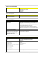
CMOS
Message Displayed
Description
CMOS Date/Time Not
Set
The CMOS date and/or time are invalid. This error can be resolved by readjusting
the system time in AMIBIOS Setup.
CMOS Battery Low
CMOS battery is low. This message usually indicates that the CMOS battery needs
to be replaced. It could also appear when the user intentionally discharges the
CMOS battery.
CMOS Settings
Wrong
CMOS settings are invalid. This error can be resolved by using AMIBIOS Setup.
CMOS Checksum
Bad
CMOS contents failed the Checksum check. Indicates that the CMOS data has
been changed by a program other than the BIOS or that the CMOS is not retaining
its data due to malfunction. This error can typically be resolved by using AMIBIOS
Setup.
Miscellaneous
Message Displayed
Description
KBC BAT Test failed
Keyboard controller BAT test failed. This may indicate a problem with keyboard
controller initialization.
Keyboard Error
Keyboard is not present or the hardware is not responding when the keyboard
controller is initialized.
PS/2 Keyboard not
found
PS/2 keyboard support is enabled in the BIOS setup but the device is not detected.
PS/2 Mouse not
found
PS/2 mouse support is enabled in the BIOS setup but the device is not detected.
Keyboard/Interface
Error
Keyboard controller failure. This may indicate a problem with system hardware.
Unlock Keyboard
PS/2 keyboard is locked. User needs to unlock the keyboard to continue the BIOS
POST.
System Halted
The system has been halted. A reset or power cycle is required to reboot the
machine. This message appears after a fatal error has been detected.
<INS> Pressed
Indicates that <INS> key is pressed during the BIOS POST. The POST will load and
use default CMOS settings.
Password check
failed
The password entered does not match the password set in the setup. This condition
may occur for both Supervisor and User password verification.
Unknown BIOS error.
Error code = 004Ah
This message is displayed when ADM module is not present in the AMIBIOS8
ROM.
Unknown BIOS error.
Error code = 004Bh
This message is displayed when language module is not present in the AMIBIOS8
ROM.
Floppy Controller
Failure
Error in initializing legacy Floppy Controller.
Aspire AX1400 Service Guide
55
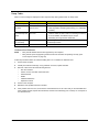
Index of Symptom-to-FRU Error Messages
To use the information in this section to diagnose a problem:
1.
Find the error symptom in the left column.
2.
If directed to a check procedure, replace the FRU indicated in the check procedure.
If no check procedure is indicated, the first Action/FRU item listed in the right column is the most likely
cause.
NOTE
If you cannot find a symptom or an error in this list and the problem remains, see “Undetermined
Problems” on page 65.
Processor/Processor Fan-related Symptoms
Symptom/Error
Action/FRU
Processor fan does not run but power
supply fan runs.
• Ensure the system is not in power saving mode.
• With the system powered on, measure the voltage of the
processor fan connector. Its reading should be +12Vdc. If the
reading shows normal, but the fan still does not work, then
replace the heat sink fan.
• Mainboard
Processor test failed.
• Processor
• Mainboard
NOTE
Normally, the processor fan should be operative, and the processor clock setting should be exactly
set to match its speed requirement before diagnosing any processor problems.
Mainboard and Memory-related Symptoms
Symptom/Error
Action/FRU
Memory test failed.
• Memory module
• Mainboard
Incorrect memory size shown or repeated
during POST.
• Insert the memory modules in the DIMM sockets properly,
then reboot the system.
• Memory module
• Mainboard
System works but fails to enter power
saving mode when the Power Management
Mode is set to Enabled.
• Enter CMOS Setup and load the default settings. In Windows
systems, check settings in Power Management Property of
the Control Panel.
• Reload software from Recovery CD.
Blinking cursor only; system does not work. • IDE drive connection/cables
• IDE disk drives
• See “Undetermined Problems”.
• Mainboard
NOTE
56
Ensure the memory modules are installed properly and the contact leads are clean before
diagnosing any system problems.
Aspire AX1400 Service Guide
Hard Disk Drive-related Symptoms
Symptom/Error
Action/FRU
Hard disk drive test failed.
• Enter CMOS Setup and load the default settings.
• Hard disk drive cable
• Hard disk drive
• Mainboard
Hard disk drive cannot format completely.
• Enter CMOS Setup and load the default settings.
• Hard disk drive cable
• Hard disk drive
• Mainboard
Hard disk drive has write error.
• Enter CMOS Setup and load the default settings.
• Hard disk drive
Hard disk drive LED fails to light, but
system operates normally.
• With the system power on, measure the voltage of the HDD
LED connector.
• HDD LED cable
NOTE
Make sure the hard disk drive is configured correctly in CMOS Setup and that cable/jumper are set
correctly before diagnosing any hard disk drive problems. (If only one drive is installed, please
make sure the drive is connected to master connector or the drive is set to master.)
Optical Disc Drive-related Symptoms
Symptom/Error
Action/FRU
CD/DVD-ROM drive LED doesn't come on
but works normally.
• Enter CMOS Setup and load the default settings.
• DIMM
• Mainboard
CD/DVD-ROM drive LED flashes for more
than 30 seconds before LED shutting off.
Software asks to reinstall disc. Software
displays a reading CD/DVD error.
• CD/DVD-ROM may have dirt or foreign material on it. Check
with a known good disc.
CD/DVD-ROM drive cannot load or eject
when the system is turned on and its eject
button is pressed and held.
• Disconnect all cables from CD/DVD-ROM drive except power
cable, then press the eject button to try to unload the disc.
• CD/DVD-ROM is not inserted properly.
• CD/DVD-ROM is damaged.
• CD/DVD-ROM drive power cable
• CD/DVD-ROM drive
CD/DVD-ROM drive does not read and
there are no messages are displayed.
• CD may have dirt or foreign material on it. Check with a
known good disc.
• Ensure the CD/DVD-ROM driver is installed properly.
• CD/DVD-ROM drive.
CD/DVD-ROM drive can play audio CD but
no sound output.
• Ensure the headphone jack of the CD/DVD-ROM has an
output.
• Turn up the sound volume.
• Speaker power/connection/cable.
• CD/DVD-ROM drive.
NOTE
Make sure the optical disc drive is configured correctly in CMOS Setup, the cable/jumper are set
correctly and the drive’s optical lens is clean before diagnosing any optical drive problems.
Aspire AX1400 Service Guide
57
Real-Time Clock-related Symptoms
Symptom/Error
Action/FRU
Real-time clock is inaccurate.
• Ensure the information in the Standard CMOS Feature of
BIOS Setup is set correctly.
• RTC battery
• Mainboard
Audio-related Symptoms
Symptom/Error
Action/FRU
Audio software program invoked but no
sound comes from speakers.
• Speaker power/connection/cable
Modem-related Symptoms
Symptom/Error
Action/FRU
Modem ring cannot wake up system from
suspend mode.
• For an external modem, make sure Power on By Ring in
BIOS Setup or Power Management is set to Enabled. For the
PCI modem, make sure Wake up by PCI card is set to
Enabled.
• If a PCI modem card is used, reinsert the modem card to the
PCI slot firmly or replace the modem card.
• In Win 98, ensure the telephone application is configured
correctly for your modem and set to receive messages and/or
fax.
Data/fax modem software program invoked
but cannot receive/send data/fax
• Ensure the modem card is installed properly.
Fax/voice modem software program
invoked but has no sound output. (Data
files are received normally; voice from
modem cannot be produced, but system
sound feature works normally.)
• Ensure the modem voice-in cable from modem adapter card
is connected to the mainboard
Video and Monitor-related Symptoms
Symptom/Error
Action/FRU
Video memory test failed.Video adapter
failed.
• Remove all non-factory-installed cards.
• Load default settings (if screen is readable).
• Mainboard
Display problem
• Monitor signal connection/cable
• Incorrect colors
• Monitor
• No high intensity
• Video adapter card
• Missing, broken, or incorrect characters
• Mainboard
• Blank monitor (dark)
• Blank monitor (bright)
• Distorted image
• Unreadable monitor
Display changing colors.
• Monitor signal connection/cable
• Video adapter card
• Mainboard
58
Aspire AX1400 Service Guide
Printer-related Symptoms
Symptom/Error
Action/FRU
Printing failed.
• Ensure the printer driver is properly installed. Refer to the
printer service manual.
• Printer
• Printer cable
• Mainboard.
Printer problems.
• Refer to the service manual for the printer.
Keyboard-related Symptoms
Symptom/Error
Action/FRU
Some or all keys on keyboard do not work.
• Keyboard
Power Supply-related Symptoms
Symptom/Error
Action/FRU
Pressing the power button does not turn off
the system. (Only unplugging the power
cord from electrical outlet can turn off the
system.)
• Ensure the Soft-off by PWR-BTTN in CMOS Setup (under
Power Management) is not set to Instant-off.
Pressing the power button does not turn on
the system
• Ensure the power override switch (located at the back of the
computer, just above the connector for the power cable) is not
set to OFF.
• Power switch cable assembly
• Power switch cable assembly.
Executing software shutdown from
Windows98 Start menu does not turn off the
system. (Only pressing power button can
turn off the system).
• Enter CMOS Setup and load the default settings.
No system power, or power supply fan is
not running.
• Power supply
Aspire AX1400 Service Guide
• Reload software from Recovery CD.
• Mainboard
59
Beep Codes
When no error message is displayed but the computer stops during POST, listen for beep codes.
Beep
Status
Possible Causes
One short beep.
System ready
System is OK.
Continuous one
long beep
Memory not installed or
memory error
• Something is wrong with the memory installed
One long beep, then VGA not installed or
two short beeps and VGA error
repeat
• There is problem accessing the memory (i.e., mainboard
problem)
• The mainboard can not access the video card for some
reasons. Either the video card is not working, its memory
is not accessible, or its BIOS may be corrupt.
• Something is wrong with the mainboard.
One long beep, then BIOS failure
one short beep
BIOS damaged. Processor jump to boot block to execute
the default procedure.
Two short beeps.
CMOS checksum error
CMOS failure
Undetermined Problems
NOTE
• Verify that all attached devices are supported by the computer.
• Verify that the power supply being used at the time of the failure is operating correctly. (See
“Power System Check” on page 45)
Follow the procedures below to isolate the failing FRU. Do not isolate non-defective FRU.
1.
Power off the computer.
2.
Visually check them for damage. If any problems are found, replace the FRU.
3.
Remove or disconnect all of the following devices:
•
Non-Acer devices
•
Printer, mouse, and other external devices
•
Hard disk drive
•
DIMM
•
CD/DVD-ROM drive
•
Expansion boards
4.
Power on the computer.
5.
Determine if the problem has been resolved.
6.
If the problem does not recur, reconnect the removed devices one at a time until you find the failed FRU.
If the problem persists, replace the mainboard, and then LCD assembly (one at a time). Do not replace a
non-defective FRU.
60
Aspire AX1400 Service Guide
BIOS Recovery
When you boot up the computer and you hear one long beep, followed by a shorter one, the system BIOS is
damaged. This maybe cause by an interruption during a BIOS flash procedure (e.g. a power outage) or a
corrupted BIOS code, which will cause the system to go into an unbootable state.You need to access and
execute the boot block program to reboot the computer and recover the regular BIOS code.
Note the following when restoring the BIOS settings:
•
Make sure the computer is connected to a UPS unit during the BIOS recovery process.
•
The BIOS crisis recovery disk should be prepared in a computer running the Windows XP or Windows
Vista OS.
Creating the BIOS Crisis Recovery Disk
1.
Prepare a removable USB storage device with a capacity size greater than 10 MB.
Note that all data on the USB storage device will be cleared during the creation of the crisis disk.
2.
Set up a computer running the Windows XP or Windows Vista operating system and plug in the USB
storage device into an available USB port.
3.
Copy the target BIOS ROM file to the USB storage device and rename it as “amiboot.rom”.
4.
Unplug the USB storage device.
5.
Eject the removable USB storage device from the computer.
Performing a BIOS Recovery
1.
Shut down the BIOS failed-computer.
2.
Connect the USB storage device containing the “amiboot.rom” file to the failed computer.
3.
Press the power button to turn on the computer.
The system will now execute the BIOS recovery process. When the process is complete, four short beeps
will be emitted and the computer will automatically reboot.
4.
Disconnect the USB storage device from the computer.
5.
Press Delete to run the CMOS Setup Utility.
6.
Press F9 to load the system default settings.
7.
Select Ok, then press Enter.
8.
Press F9 to save the default settings and close the Setup utility.
9.
Select Ok, then press Enter.
Aspire AX1400 Service Guide
61
BIOS Update
Updating the BIOS in DOS Mode
1.
Press the power button to turn on the computer and boot to DOS mode.
2.
Key in 'cd dostool'. (Go to BIOS path like "A:\DOSTOOL")
3.
Key in 'flash1M.bat' or 'flash1M'.
4.
Press Enter to flash the system BIOS.
5.
Reboot the computer.
6.
Press Delete to run the CMOS Setup Utility.
7.
Press F9 to load the system default settings.
8.
Select Ok, then press Enter.
9.
Press F9 to save the default settings and close the Setup utility.
10. Select Ok, then press Enter.
62
Aspire AX1400 Service Guide
Updating the BIOS in Windows Mode
This BIOS updating procedure is for a computer running a 32- or 64-bit Windows OS.
1.
Press the power button to turn on the computer.
2.
Click Start | Command Prompt | Run as administrator.
3.
Perform the steps below if your computer is running 32-bit Windows.
a.
Key in 'cd wintool\32'. (Go to BIOS path like "D:\WinTool\32")
b.
Key in 'flash1M.bat' or 'flash1M'.
Aspire AX1400 Service Guide
63
c.
4.
64
Press Enter to flash the system BIOS.
Perform the steps below if your computer is running 64-bit Windows.
a.
Key in 'cd wintool\64'. (Go to BIOS path like "D:\WinTool\64")
b.
Key in 'flash1M.bat' or 'flash1M'.
Aspire AX1400 Service Guide
c.
Press Enter to flash the system BIOS.
5.
Reboot the computer.
6.
Press Delete to run the CMOS Setup Utility.
7.
Press F9 to load the system default settings.
8.
Select Ok, then press Enter.
9.
Press F9 to save the default settings and close the Setup utility.
10. Select Ok, then press Enter.
Aspire AX1400 Service Guide
65
Clearing CMOS
You may need to clear the Setup configuration values (CMOS) if the configuration has been corrupted, or if
incorrect settings made in the Setup Utility caused error messages to be unreadable. This procedure will clear
the BIOS supervisor password as well.
Use the JBIOS1 jumper to clear the CMOS data.
•
1-2 position: Normal operation (default)
•
2-3 position: Clear CMOS data
To clear the CMOS data:
1.
Turn off the power to the computer and all peripherals.
2.
Unplug the power cord from the computer.
3.
Unplug the network cable and all connected peripheral devices from the computer.
4.
Place the computer on a flat, steady surface.
5.
Remove the side panel.
6.
If necessary, remove any expansion cards, assemblies or cables that prevent access to the CMOS clear
jumper.
7.
Locate the JBIOS1 jumper on the mainboard.
8.
Remove the jumper block and set it over the 2-3 pins for 20 to 30 seconds.
9.
Return the jumper block to its default 1-2 position.
10. Reinstall any expansion card, peripheral, and system cables that have previously been removed.
11. Reinstall the side panel.
12. Connect the AC power cord to the system.
13. Press the power button
to turn on the computer.
14. During POST, press Delete to access the Setup Utility.
15. Press F9 to load the system default values.
16. Press F10 to save the changes you made and close the Setup Utility.
66
Aspire AX1400 Service Guide
Chapter 5
System Architecture
This chapter shows the block diagram and board layout of the Aspire AX1400 computer.
Block Diagram
The core subsystems of the Aspire AX1400 computer are depicted in the following block diagram.
Aspire AX1400 Service Guide
67
Mainboard Layout
This section shows the major mainboard components.
68
No.
Label
Description
No.
Label
Description
1
U1
CPU socket
12
PCIEX16
PCIEX16 Slot
2
CPUFAN1
CPU cooling fan connector
13
PCIEX1
PCIEX1 36-pin slot
3
DIMM1-2
DDR3 240-pin slots
14
U2
ALC662
4
U23
ITE 8758
15
AUDJACK2
Line in/Line Out/MIC
5
PWR2
Standard 24-pin power connector
16
USBLAN1
RJ45+USB connector
6
SATA1-2
Serial ATA connectors
17
USBR1
USB-A 8P connector
7
DEBUGH1
12-pin DEBUG port
18
VGA1
VGA connector
8
LEDH1
12-pin power cable header
19
PWR1
ATX 4-pin connector
9
USBF 2-3
Front panel USB header
20
KBMSCONN1
Keyboard and mouse connectors
10
USBF 1
Front panel card reader header
21
JBIOS1
Clear CMOS jumper
11
AUDIOF1
Front panel audio jack header
Aspire AX1400 Service Guide
Jumper Setting
This section explains how to set the jumper for correct configuration of the main board.
Jumpers with more than one pin are numbered. When setting a jumper, ensure that the jumper caps are
placed on the correct pins.
The following illustration shows the location of JBIOS1.
The following table shows the settings of the 3-pin Clear CMOS (JBIOS1) jumper. Place the jumper cap on
pins 1 and 2 to close or short the jumper. Place the jumper cap on pins 2 and 3 to open or clear the jumper.
Jumper
Type
Description
Setting (default)
JBIOS1
3-pin
Clear CMOS
1-2: Close (default)
2-3: Open
Before clearing the CMOS,
make sure to turn off the
system.
Aspire AX1400 Service Guide
69
Internal header pin definition
Header Name
70
Function
Definition
CPU FAN HEADER
1: GND
2: +12V
3: SENSE
4: PWM CONTROL
FRONT PANEL HEADER
1: SATALED+
2: ACPI_LED
3: SATALED4: PWR_LED
5: GND
6: PWR_SW
7: RESET
8: GND
9: NC
10: Key
11: NC
12: VCC
13: NC
14: -ACTIVE_C
FRONT USB HEADER
1: USBVCC_1
2: USBVCC_1
3: USB0_XN
4: USB1_XN
5: USB0_XP
6: USB1_XP
7:GND
8: GND
9: KEY
10: GND
FRONT USB HEADER
1: USBVCC_2
2: USBVCC_2
3: USB2_XN
4: USB4_XN
5: USB2_XP
6: USB4_XP
7:GND
8: GND
9: KEY
10: GND
FRONT AUDIO HEADER
1: PORT-F_L
2: AUGND
3: PORT-F_R
4: FRONT_AUD_DET
5: PORT-E_R
6: MIC2_JD
7: AUGND
8: KEY
9: PORT-E_L
10: LINE2_JD
Aspire AX1400 Service Guide
Connector pin definition
Header Name
Aspire AX1400 Service Guide
Function
Definition
PSKBMS CONN
1: KBDATA
2: NC
3: GND
4: KBVCCSB
5: KBCLK
6: NC
7: MSDATA
8: NC
9: GND
10: KBVCCSB
11: MSCLK
12: NC
13: GND
14: GND
15: GND
16: GND
17: GND
VGA CONN
1: RED
2: GREEN
3: BLUE
4,11: NC
9: HDMIVCC
12: VDAC_SDAT
13: HSYNC
14: VSYNC
15: VDAC_SCLK
5,6,7,8,10,16,17: GND
SATA CONN
1: GND
2: SATA0_TX_P
3: SATA0_TX_N
4: GND
5: SATA0_RX_N
6: SATA0_RX_P
7: GND
SATA CONN
1: GND
2: SATA1_TX_P
3: SATA1_TX_N
4: GND
5: SATA1_RX_N
6: SATA1_RX_P
7: GND
ATX_POWER CONN
1:VCC3 13:VCC3
2:VCC3 14:-12V
3: GND 15:GND
4:VCC 16:ATX_PSON_L
5:GND 17:GND
6:VCC 18:GND
7:GND 19:GND
8:ATX_PWRGD 20:NC
9:5VSB 21VCC
10:+12V 22:VCC
11:+12V 23:VCC
12:VCC3 24:GND
71
Header Name
Function
Definition
ATX12V CONN
1: GND
2: GND
3: +12V_4P
4: +12V_4P
Connecting Optional Devices
Refer to the following for information on connecting the main board’s optional devices:
SATA1~2: Serial ATA connectors
These connectors are used to support the new Serial ATA devices for the highest datatransfer rates
(3.0 Gb/s), simpler disk drive cabling and easier PC assembly. It elimi-nates limitations of the current Parallel
ATA interface. But maintains register com-patibility and software compatibility with Parallel ATA.
72
Pin
Signal Name
Pin
Signal Name
1
Ground
2
TX+
3
TX-
4
Ground
5
RX-
6
RX+
7
Ground
Aspire AX1400 Service Guide
AUDIOF1: Front Panel Audio header
This header allows the user to install auxiliary front-oriented microphone and line-out ports for easier access.
Pin
Signal Name
Pin
Signal Name
1
PORT 1L
2
AUD_GND
3
PORT 1R
4
PRESENCE#
5
PORT 2R
6
SENSE1_RETURN
7
SENSE_SEND
8
KEY
9
PORT 2L
10
SENSE2_RETURN
USBF1~3: Front Panel USB headers
The motherboard has two USB ports installed on the rear edge I/O port array.Additionally, some computer
cases have USB ports at the front of the case. If youhave this kind of case, use auxiliary USB connector to
connect the front-mountedports to the motherboard.
Pin
Signal Name
Function
1
USBPWR
Front Panel USB Power
2
USBPWR
Front Panel USB Power
3
USB_FP_P0-
USB Port 0 Negative Signal
4
USB_FP_P1-
USB Port 1 Negative Signal
5
USB_FP_P0+
USB Port 0 Positive Signal
6
USB_FP_P1+
USB Port 1 Positive Signal
7
GND
Ground
8
GND
Ground
9
Key
No pin
10
USB_FP_OC0
Overcurrent signal
Aspire AX1400 Service Guide
73
Connecting Case Components
After you have installed the motherboard into a case, you can begin connecting themotherboard components.
Refer to the following:
1.
Connect the CPU cooling fan cable to CPUFAN1.
2.
Connect the standard power supply connector to PWR2.
3.
Connect the case switches and indicator LEDs to the LEDH1.
4.
Connect the auxiliary case power supply connector to PWR1.
CPUFAN1: CPU Cooling Fan Power Connector
74
Pin
Signal Name
Function
1
GND
System ground
2
+12V
Power +12V
3
Sense
Sensor
4
PWM
PWM
Aspire AX1400 Service Guide
PWR2: ATX 24-pin Power Connector
Pin
Signal Name
Pin
Signal Name
1
+3.3V
13
+3.3V
2
+3.3V
14
-12V
3
Ground
15
Ground
4
+5V
16
PS_ON
5
Ground
17
Ground
6
+5V
18
Ground
7
Ground
19
Ground
8
PWRGD
20
-5V
9
+5VSB
21
+5V
10
+12V
22
+5V
11
+12V
23
+5V
12
+3.3V
24
Ground
PWR1: ATX 12V Power Connector
Pin
Signal Name
1
Ground
2
Ground
3
+12V
4
+12V
Front Panel Header
The front panel header (LEDH1) provides a standard set of switch and LED headers commonly found on ATX
or micro-ATX cases. Refer to the table below for information:
LEDH1
Pin
Signal Name
Function
Pin
Signal Name
Function
1
VCC
Reset Switch (+)
2
GLED0
*MSG LED (+)
3
HDD_LEDN
Hard disk LED (-)
4
GLED1
*MSG LED (-)
5
GND
Reset Switch (-)
6
PWRSW
Power Switch (+)
7
HWRST_L
Reset Switch (+)
8
GND
Power Switch (-)
9
F_PANEL_DET
Reserved
10
KEY
No pin
11
NC
Reserved
12
VCC
Reset Switch (+)
13
NC
Reserved
14
F_LAN_LED
Reset Switch (+)
Aspire AX1400 Service Guide
75
76
Aspire AX1400 Service Guide
Chapter 6
Field Replaceable Unit (FRU) List
This chapter gives you the FRU (Field Replaceable Unit) listing of the Aspire AX1400 computer global
configurations. Refer to this list when ordering for repair parts or for RMA (Return Merchandise Authorization).
IMPORTANT
NOTE
When ordering FRU parts, check the most up-to-date information available on your regional
web or channel. For whatever reasons a part number is changed, it will NOT be noted on the
printed Service Guide. For Acer authorized service providers, your Acer office may have a
different part number code from those given in the FRU list of this printed Service Guide. You
MUST use the local FRU list provided by your regional Acer office to order FRU parts for
service.
Follow the local government regulations, or the rules set by your regional office on how to return or
dispose of defective parts.
Exploded Diagram
Aspire AX1400 Service Guide
77
Aspire AX1400 FRU List
ACER_AX1400_AMANALO(NO: 91.3BU01.A01G )
Category
Part Name
Description
Acer Part No.
BOARDS
CARD READER 9 IN 1 8.5L
AU6476 W/USB2.0 & USB
CABLE W/O 1394
CR 9-IN-1 ALCOR
AU6476, 420MM USB
CABLE
CR.10400.102
CARD READER 9 IN 1 8.5L
AU6475 W/USB2.0 & USB
CABLE W/O 1394
CR 9-IN-1 RI727 ALCOR
AU6475, 420MM USB
CR.10400.107
FRONT IO BOARD CENTURY
W/AUDIO CABLE*1&USB
CABLE*2
F-IO BOARD/2AUDIO
JACK+2USB CO
55.SC101.001
MODEM CARD LITE-ON D1156E#A10A LOW-PROFILE
PCI-E 56K V.92
MODEM 56K ATX LSI
UNIVERSAL (P
FX.10100.003
MODEM CARD 56K PRO-NETS
PRONETS VD56UL EXTERNAL
USB REV 1.0
MODEM PRO-NETS
VD56UL EXTERNAL
FX.10100.023
WIRELESS LAN BOARD
802.11BGN LITEON WN7600R
WLAN 802.11BGN
RALINK MC 1*2
NI.10200.009
WIRELESS LAN BOARD
802.11BGN PRONETS
WU71RL USB
WLAN 802.11 BGN
WU71RL USB
NI.10200.023
WIRELESS LAN BOARD
802.11BGN 1X1 RALINK
RT3090 LOW-PROFILE
WLAN 802.11BGN 1X1
NI.10200.038
RALINK RT3090 (LOW-PR
VGA CARD PCPARTNER 2881N141-A00AC NVIDIA GT315
512MB SDDR3 DVI+HDMI ATX
(SAMSUNG)
PCP NV GT315 512MB
SDDR3 SDI
VG.PCPT3.153
VGA CARD PCPARTNER 2881E145-A01AC HD5450 512MB
SDDR3 64BITS SAMSUNG DVI
HDMI W/LP BRACKET ROHS
VGA CARD 5450 512MB
SDDR3 SDI
VG.APC54.511
DVI TO VGA DONGLE
CONNECTOR
DVI TO VGA DONGLE
D0.VGA26.P01
HDD SATA CABLE
C.A. SATA HDD BOXERII
50.SC101.003
LED SWITCH CABLE
C.A. LED SWITCH BOXER
X350
50.SE301.002
ODD SATA CABLE
C.A. SATA ODD BOXERII
50.SC101.002
POWER CORD 250V 3PIN
1800MM UK
POWER CORD 1800MM
250V UK
27.03118.031
CABLES
78
Aspire AX1400 Service Guide
Category
Part Name
Description
Acer Part No.
CASE/COVER/BRACKET
ASSEMBLY
FRONT IO BRACKET
BRKT F-IO BOXER X350
33.SE301.001
ASSY MAIN-CHASSIS MCP61
BOXER X350
ASSY MAIN-CHASSIS
MCP61 BOXER X350
60.SE901.001
UPPER CASE
CAS UP BOXER X350
60.SE201.002
LOWER CASE
ASSY LCASE-ASM
MCP61 BOXER X350
60.SE901.002
HDD&ODD COVER BRACKET
ASSY ODD-HDD-ASM
BOXER X3
33.SC101.002
FRONT BEZEL W/LED SWITCH
CABLE
ASSY MAIN-BEZEL
BOXER X350
60.SE201.004
CPU AMD ATHLON II X2 240
2.8GHZ 2M L2 CACHE 65W
REGOR
IC CPU ATHLON II X2 240
2.8GHZ
KC.AT202.240
CPU AMD CPU ATHLON II X2
215 65W 2.7G
ADX215OCK22GQ
IC CPU ATHLON II X2 215
65W 2.
KC.AT202.215
CPU AMD ATHLON II X2 245
2.9GHZ 2M L2 CACHE 65W
REGOR
IC CPU ATHLON II X2 245
2.9GHZ
KC.AT202.245
CPU AMD ATHLON II X2 250
3.0GHZ 2M L2 CACHE 65W
REGOR ATHIIX2250
IC CPU ATHLON II X2 250
3.0GHZ
KC.AT202.250
CPU AMD ATHLONII 255 AM3+
2X1M 4000 940 65W C-2 3.1G
DUAL CORE
IC CPU ATHLONII 255
AM3+ 2X1M
KC.AT202.255
CPU AMD ATHLONII B22 AM3+
2.8G 2X1M 4000 940 65W C-2
DUAL CORD
IC CPU ATHLONII B22
AM3+ 2.8G
KC.AT202.B22
CPU AMD ATHLONII B24 AM3+
3.0G 2X1M 4000 940 65W C-2
DUAL CORD
IC CPU ATHLONII B24
AM3+ 3.0G
KC.AT202.B24
CPU AMD ATHLONII 235E
AM3+ 2.7G 2X1M 4000 940
45W C-2 DUAL CORD
IC CPU ATHLONII 235E
AM3+ 2.7G
KC.AE202.235
CPU AMD ATHLONII 240E
AM3+ 2.8G 2X1M 4000 940
45W C-2 DUAL CORE
IC CPU ATHLON II X2
240E 2.8G
KC.AE202.240
CPU AMD ATHLON II X3 400E
2.2GHZ 1.5M L2 CACHE 45W
RANA ATHIIX3400E
IC CPU ATHLON II X3
400E 2.2GH
KC.AE202.400
CPU AMD ATHLON II X3 405E
2.3GHZ 1.5M L2 CACHE 45W
RANA ATHIIX3405E
IC CPU ATHLON II X3
405E 2.3GH
KC.AE202.405
CPU AMD ATHLONII 160U
AM3+ 1.8G 1M 3600 940 20W
C-2 SINGLE CORE
IC CPU ATHLONII 160U
AM3+ 1.8G
KC.AU202.160
CPU AMD ATHLONII 250U
AM3+ 1.6G 2X1M 3200 940
25W C-2 DUAL CORE
IC CPU ATHLONII 250U
AM3+ 1.6G
KC.AU202.250
CPU AMD ATHLONII 260U
AM3+ 1.8G 2X1M 3600 940
25W C-2 DUAL CORE
IC CPU ATHLONII 260U
AM3+ 1.8G
KC.AU202.260
CPU/PROCESSOR
Aspire AX1400 Service Guide
79
Category
Part Name
Description
Acer Part No.
CPU/PROCESSOR
CPU AMD PHENOMII X 3 700E
2.4GHZ 7.5M TOTAL CACHE
65W HEKA PHNMII700E
IC CPU PHENOMII X 3
700E 2.4GH
KC.PE202.700
CPU AMD PHENOMII X 3 705E
2.5GHZ 7.5M TOTAL CACHE
65W HEKA PHNMII705E
IC CPU PHENOMII X 3
705E 2.5GH
KC.PE202.705
CPU AMD SEMPRON 140 2.7G
45W PGA
IC CPU SEMPRON 140
2.7G 45W PGA
KC.SMP02.140
ODD PLDS SUPER-MULTI
DRIVE HH 16X DH-16AASH
BLACK BEZEL SATA FOR
HF+WINDOWS7
ODD HH SM HF+W7
PLDS DH-16AASH
KU.0160F.009
ODD HLDS SUPER-MULTI
DRIVE HH 16X GH41N BLACK
BEZEL SATA HF + WIN 7
ODD HH SM HF+W7
HLDS GH-41N
KU.0160D.049
ODD HLDS DVD-ROM HH 16X
TRAY DH20N LF BLACK BEZEL
SATA HF+WIN 7
DVD ROM HH HF+W7
HLDS DH20N
KV.0160D.016
DVD-RW DRIVE
ODD PLDS DVD-ROM HH DL
DVD ROM HH HF+W7 DH- KV.0160F.002
16X TRAY DH-16D5SH LF
16D5SH
BLACK BEZEL SATA HF+WIN 7
HDD/HARD DISK DRIVE
80
HDD 320GB 3.5" 7200RPM
SATA II SEAGATE PHARAOH
8MB NCQ
HDD 320G 3.5" SEAGATE
PHARAOH
KH.32001.015
HDD 320GB 3.5" 7200RPM
SATA II 8MB HGST
HDT721032SLA380 SATURN
HDD 320GB HGST
HDT721032SLA380
KH.32007.006
HDD 320GB 3.5" 7200RPM
SATA II 16MB HGST
HDS721032CLA362 JUPITER
HDD 320GB 3.5" HGST
HDS721032CLA362 7.2K
KH.32007.011
HDD 320GB 3.5" 7200RPM
SATA II WD WD3200AAJS22L7A0 XL320S
HDD 320GB WD
WD3200AAJS-22L7A0
KH.32008.016
HDD 3.5" 500GB 7200RPM
SATA SEAGATE PHARAOH
ST3500418AS
HDD 500GB SGT
ST3500418AS 7.2K
KH.50001.012
HDD 500GB 3.5" 7200RPM
SATA II 16MB HGST
HDS721050CLA362 JUPITER
HDD 500GB HGST
HDS721050CLA362
KH.50007.012
HDD 3.5" 500GB 7200RPM
SATA WD XL320M
WD5000AAKS-22M9A0
HDD 500GB
WD5000AAKS-22V1A0
KH.50008.014
HDD 640GB 3.5" 7200RPM
HGST HDT721064SLA360
SATURN SATA
HDD 640GB HGST
HDT721064SLA360
KH.64007.001
HDD 640GB 3.5" 7200RPM
SATA II 32MB HGST
HDS721064CLA332 JUPITER
HDD 640GB HGST
HDS721064CLA332
KH.64007.002
HDD 640GB 3.5" 7200RPM
SATA II WD WD6400AAKS22A7B2 XL320-M
HDD 640GB WD
WD6400AAKS-22A7B2
KH.64008.003
HDD 3.5" 1000GB 7200RPM
SATA SEAGATE SEAGATE
ST31000528AS LF
HDD 1TB SGT
ST31000528AS 7.2KR
KH.01K01.007
Aspire AX1400 Service Guide
Category
Part Name
Description
Acer Part No.
HDD/HARD DISK DRIVE
HDD 1TB 3.5" 5400RPM SATAII
WD10EADS-22M4B0 8MB GP
HDD 1TB WD10EADS22M2B0 GP
KH.01K08.005
HDD 1TB 3.5" 7200RPM SATA
HGST SATURN
HDT721010SLA360
HDD 1TB HGST
HDT721010SLA360
KH.01K07.002
HDD 1TB 3.5" 7200RPM SATA II
32MB HGST
HDS721010CLA332 JUPITER
HDD 1TB HGST
HDS721010CLA332
KH.01K07.003
HDD 1.5TB 3.5" 5400RPM SATA
WD GP500 WD15EADS22P8B0 32MB GP
HDD 1.5TB WD15EADS22P8B0 GP
KH.15K08.001
HDD 1.5TB 3.5" 7200RPM SATA
SEAGATE BRINKS
ST31500341AS 32MB CC4H 7
HDD 1.5TB SGT
ST31500341AS 7.2
KH.15K01.002
CPU HEATSINK AIR COOLER
LGA775 72*72 65W AVC
COOLER LGA775 72*72
65W AVC
HI.10800.035
CPU COOLER LGA775 45W
72*72 AVC
COOLER LGA775 72*72
45W AVC
HI.10800.024
KEYBOARD PS/2 104 KEY
CHICONY KB-07593US25522V
BLACK US W/O EKEY
KB CHICONY KB-0759
PS/2 104K B
KB.PS203.284
KEYBOARD PS/2 104 KEY
BLACK TRADITIONAL
CHINESE W/O EKEY
KB CHICONY KB-0759
PS/2 104K B
KB.PS203.285
KEYBOARD PS/2 104 KEY
SIMPLIFIED CHINESE W/O
EKEY
KB CHICONY KB-0759
PS/2 104K B
KB.PS203.286
KEYBOARD PS/2 104 KEY
CHICONY KB-07593U425522V
BLACK US INTERNATIONAL
W/O EKEY
KB CHICONY KB-0759
PS/2 104K B
KB.PS203.287
KEYBOARD PS/2 104 KEY
CHICONY KB-07593A025522V
BLACK ARABIC ENGLISH W/O
EKEY
KB CHICONY KB-0759
PS/2 104K B
KB.PS203.288
KEYBOARD PS/2 104 KEY
CHICONY KB-07593T025522V
BLACK THAILAND W/O EKEY
KB CHICONY KB-0759
PS/2 104K B
KB.PS203.289
KEYBOARD PS/2 105 KEY
CHICONY CHICONY BLACK
SPANISH W/O EKEY
KB CHICONY KB-0759
PS/2 105K B
KB.PS203.290
KEYBOARD PS/2 105 KEY
BLACK PORTUGUESE W/O
EKEY
KB CHICONY KB-0759
PS/2 105K B
KB.PS203.291
KEYBOARD PS/2 105 KEY
CHICONY KB-07596CA25522V
BLACK CANADIAN FRENCH
KB CHICONY KB-0759
PS/2 105K B
KB.PS203.292
KEYBOARD PS/2 107 KEY
BLACK BRAZILIAN
PORTUGUESE
KB CHICONY KB-0759
PS/2 107K B
KB.PS203.293
KEYBOARD PS/2 109 KEY
BLACK JAPANESE W/O EKEY
KB CHICONY KB-0759
PS/2 109K B
KB.PS203.294
KEYBOARD PS/2 105 KEY
CHICONY KB-07596D125522V
BLACK GERMAN W/O EKEY
KB CHICONY KB-0759
PS/2 105K B
KB.PS203.295
HEATSINK
KEYBOARD
Aspire AX1400 Service Guide
81
82
Category
Part Name
Description
Acer Part No.
KEYBOARD
KEYBOARD PS/2 105 KEY
CHICONY KB-07596I125522V
BLACK ITALIAN W/O EKEY
KB CHICONY KB-0759
PS/2 105K B
KB.PS203.296
KEYBOARD PS/2 105 KEY
CHICONY KB-07596F125522V
BLACK FRENCH W/O EKEY
KB CHICONY KB-0759
PS/2 105K B
KB.PS203.297
KEYBOARD PS/2 105 KEY
CHICONY KB-07596S025522V
BLACK SWEDISH W/O EKEY
KB CHICONY KB-0759
PS/2 105K B
KB.PS203.298
KEYBOARD PS/2 105 KEY
CHICONY KB-07596GB25522V
BLACK UK W/O EKEY
KB CHICONY KB-0759
PS/2 105K B
KB.PS203.299
KEYBOARD PS/2 105 KEY
BLACK DUTCH W/O EKEY
KB CHICONY KB-0759
PS/2 105K B
KB.PS203.300
KEYBOARD PS/2 105 KEY
CHICONY KB-07596CH25522V
BLACK SWISS/G W/O EKEY
KB CHICONY KB-0759
PS/2 105K B
KB.PS203.301
KEYBOARD PS/2 105 KEY
BLACK BELGIUM W/O EKEY
KB CHICONY KB-0759
PS/2 105K B
KB.PS203.302
KEYBOARD PS/2 105 KEY
BLACK ICELANDIC W/O EKEY
KB CHICONY KB-0759
PS/2 105K B
KB.PS203.303
KEYBOARD PS/2 105 KEY
CHICONY KB-07596N025522V
BLACK NORWEGIAN W/O
EKEY
KB CHICONY KB-0759
PS/2 105K B
KB.PS203.304
KEYBOARD PS/2 104 KEY
BLACK US INTERNATIONAL
W/ HEBREW W/O EKEY
KB CHICONY KB-0759
PS/2 104K B
KB.PS203.305
KEYBOARD PS/2 105 KEY
BLACK US INTERNATIONAL
W/ HEBREW W/O EKEY
KB CHICONY KB-0759
PS/2 105K B
KB.PS203.306
KEYBOARD PS/2 105 KEY
KB CHICONY KB-0759
BLACK SLOVENIAN W/O EKEY PS/2 105K B
KB.PS203.307
KEYBOARD PS/2 105 KEY
BLACK SLOVAK W/O EKEY
KB CHICONY KB-0759
PS/2 105K B
KB.PS203.308
KEYBOARD PS/2 104 KEY
CHICONY KB-07593S325522V
BLACK RUSSIAN W/O EKEY
KB CHICONY KB-0759
PS/2 104K B
KB.PS203.309
KEYBOARD PS/2 105 KEY
BLACK HUNGARIAN W/O
EKEY
KB CHICONY KB-0759
PS/2 105K B
KB.PS203.310
KEYBOARD PS/2 104 KEY
CHICONY KB-07593GR25522V
BLACK GREEK W/O EKEY
KB CHICONY KB-0759
PS/2 104K B
KB.PS203.311
KEYBOARD PS/2 105 KEY
BLACK DANISH W/O EKEY
KB CHICONY KB-0759
PS/2 105K B
KB.PS203.312
KEYBOARD PS/2 104 KEY
BLACK CZECH W/O EKEY
KB CHICONY KB-0759
PS/2 104K B
KB.PS203.313
KEYBOARD PS/2 105 KEY
BLACK ROMANIAN W/O EKEY
KB CHICONY KB-0759
PS/2 105K B
KB.PS203.314
KEYBOARD PS/2 105 KEY
BLACK TURKISH W/O EKEY
KB CHICONY KB-0759
PS/2 105K B
KB.PS203.315
KEYBOARD PS/2 105 KEY
BLACK SPANISH LATIN W/O
EKEY
KB CHICONY KB-0759
PS/2 105K B
KB.PS203.316
Aspire AX1400 Service Guide
Category
Part Name
Description
Acer Part No.
KEYBOARD
KEYBOARD PS/2 104 KEY
BLACK KAZAKH W/O EKEY
KB CHICONY KB-0759
PS/2 104K B
KB.PS203.319
KEYBOARD PS/2 104 KEY
BLACK TURKMEN W/O EKEY
KB CHICONY KB-0759
PS/2 104K B
KB.PS203.320
KEYBOARD PS/2 105 KEY
CHICONY KB-07596DN25522V
BLACK NORDIC W/O EKEY
KB CHICONY KB-0759
PS/2 105K B
KB.PS203.321
KEYBOARD PS/2 104 KEY
BLACK SIMPLIFIED CHINESE
W/O EKEY
KB CHICONY KB-0759
PS/2 104K B
KB.PS203.322
KEYBOARD PS/2 104 KEY
BLACK US W/O EKEY
KB CHICONY KB-0759
PS/2 104K B
KB.PS203.323
KEYBOARD PS/2 105KEY
CHICONY KB-07596CU25522V
BLACK ENGLISH/CABADIAN
FRENCH
KB CHICONY KB-0759
PS/2 105K B
KB.PS203.328
KEYBOARD PS2 104 KEY
LITEON SG-30610-XUW
BLACK US W/O EKEY
KEYBOARD PS2 SK-9620
SG-30600
KB.PS20B.069
KEYBOARD PS2 104 KEY
LITEON SG-30610-XLW BLACK
TRADITIONAL CHINESE W/O
EKEY
KB PS2 SK-9620 SG30600-XMW TC
KB.PS20B.070
KEYBOARD PS/2 104 KEY
BLACK CHINESE W/O EKEY
KB PS2 SK-9620 SG30600-XLW CN
KB.PS20B.071
KEYBOARD PS/2 104 KEY
BLACK US INTERNATIONAL
W/O EKEY
KEYBOARD PS2 SK-9620
SG-30601
KB.PS20B.072
KEYBOARD PS/2 104 KEY
BLACK ARABIC ENGLISH W/O
EKEY
KB SK-9620 104K AE NO
EURO#NIW
KB.PS20B.073
KEYBOARD PS2 104 KEY
LITEON SG-30610-33W BLACK
THAILAND W/O EKEY
KEYBOARD PS2 SK-9620
SG-30600
KB.PS20B.074
KEYBOARD PS2 105 KEY
LITEON SG-30610-2EW BLACK
SPANISH W/O EKEY
KEYBOARD PS2 SK9620
SG-30610
KB.PS20B.075
KEYBOARD PS/2 105 KEY
BLACK PORTUGESE W/O
EKEY
KEYBOARD PS2 SK-9620
SG-30600
KB.PS20B.076
KEYBOARD PS2 105 KEY
LITEON SG-30610-23W BLACK
CANADIAN FRENCH W/O
EKEY
KEYBOARD PS2 SK-9620
SG-30600
KB.PS20B.077
KEYBOARD PS/2 107 KEY
BLACK BRAZILIAN
PORTUGUESE W/O EKEY
KB SK-9620 107K PT/BR
NO EURO#
KB.PS20B.078
KEYBOARD PS/2 109 KEY
BLACK JAPANESE W/O EKEY
KEYBOARD PS2 SK-9620
SG-30600
KB.PS20B.079
KEYBOARD PS2 105 KEY
KEYBOARD PS2 SK-9620
LITEON SG-30610-2DW BLACK SG-30600
GERMAN W/O EKEY
KB.PS20B.080
KEYBOARD PS2 105 KEY
LITEON SG-30610-2IW BLACK
ITALIAN W/O EKEY
KB.PS20B.081
Aspire AX1400 Service Guide
KEYBOARD PS2 SK-9620
SG-30600
83
84
Category
Part Name
Description
Acer Part No.
KEYBOARD
KEYBOARD PS2 105 KEY
LITEON SG-30610-2FW BLACK
FRENCH W/O EKEY
KEYBOARD PS2 SK-9620
SG-30600
KB.PS20B.082
KEYBOARD PS/2 105 KEY
BLACK SWEDEN W/O EKEY
KEYBOARD PS2 SK-9620
SG-30600
KB.PS20B.083
KEYBOARD PS2 105 KEY
LITEON SG-30610-2BW BLACK
UK W/O EKEY
KEYBOARD PS2 SK-9620
SG-30600
KB.PS20B.084
KEYBOARD PS/2 105 KEY
BLACK DUTCH W/O EKEY
KEYBOARD PS2 SK-9620
SG-30600
KB.PS20B.085
KEYBOARD PS/2 105 KEY
BLACK SWISS/G W/O EKEY
KB SK-9620 105K
CHEURO#NIW/
KB.PS20B.086
KEYBOARD PS/2 105 KEY
BLACK BELGIUM W/O EKEY
KEYBOARD PS2 SK-9620
SG-30600
KB.PS20B.087
KEYBOARD PS/2 109 KEY
BLACK JAPANESE W/O EKEY
KEYBOARD PS2 SK-9620
SG-30600
KB.PS20B.088
KEYBOARD PS/2 105 KEY
BLACK NORWEGIAN W/O
EKEY
KEYBOARD PS2 SK-9620
SG-30600
KB.PS20B.089
KEYBOARD PS/2 104 KEY
BLACK US INTERNATIONAL
W/ HEBREW W/O EKEY
KEYBOARD PS2 SK-9620
SG-30600
KB.PS20B.090
KEYBOARD PS/2 105 KEY
BLACK POLISH W/O EKEY
KB SK-9620 105K PLNO
EURO#N
KB.PS20B.091
KEYBOARD PS/2 105 KEY
KEYBOARD PS2 SK-9620
BLACK SLOVENIAN W/O EKEY SG-30600
KB.PS20B.092
KEYBOARD PS/2 104 KEY
KB SK-9620 104K SLO
BLACK SLOVENIAN W/O EKEY EURO#NIW/O
KB.PS20B.093
KEYBOARD PS2 104 KEY
KEYBOARD PS2 SK-9620
LITEON SG-30610-XAW BLACK SG-30600
RUSSIAN W/O EKEY
KB.PS20B.094
KEYBOARD PS/2 105 KEY
BLACK HUNGARIA W/O EKEY
KEYBOARD PS2 SK-9620
SG-30600
KB.PS20B.095
KEYBOARD PS/2 104 KEY
BLACK GREEK W/O EKEY
KEYBOARD PS2 SK-9620
SG-30600
KB.PS20B.096
KEYBOARD PS/2 105 KEY
BLACK DENMARK W/O EKEY
KEYBOARD PS2 SK-9620
SG-30600
KB.PS20B.097
KEYBOARD PS/2 104 KEY
BLACK CZECH W/O EKEY
KEYBOARD PS2 SK-9620
SG-30600
KB.PS20B.098
KEYBOARD PS/2 105 KEY
BLACK ROMANIAN W/O EKEY
KEYBOARD PS2 SK-9620
SG-30600
KB.PS20B.099
KEYBOARD PS/2 105 KEY
BLACK TURKISH W/O EKEY
KEYBOARD PS2 SK-9620
SG-30600
KB.PS20B.100
KEYBOARD PS2 105 KEY
LITEON SG-30610-29W BLACK
SPANISH LATIN W/O EKEY
KB SK-9620 105K LAT
EURO#NIW/O
KB.PS20B.101
KEYBOARD PS/2 105 KEY
BLACK TURKISH-Q W/O EKEY
KB SK-9620 105K TR-Q
EURO#NIW/
KB.PS20B.102
KEYBOARD PS/2 105 KEY
BLACK ARABIC FRENCH W/O
EKEY
KEYBOARD PS2 SK-9620
SG-30600
KB.PS20B.103
KEYBOARD PS/2 105 KEY
BLACK KAZAKH W/O EKEY
KB SK-9620 105K KA NO
EURO#NIW
KB.PS20B.104
Aspire AX1400 Service Guide
Category
Part Name
Description
Acer Part No.
KEYBOARD
KEYBOARD PS/2 104 KEY
BLACK TURKMEN W/O EKEY
KB SK-9620 104K TMNO
EURO#NIW/
KB.PS20B.105
KEYBOARD PS2 105 KEY
LITEON SG-30610-79W BLACK
NORDIC W/O EKEY
KB SK-9620 105K NR
EURO#NIW/O
KB.PS20B.106
KEYBOARD PS/2 105KEY
LITEON SG-30610-93W BLACK
ENGLISH/CANADIAN FRENCH
KB PS2 SK-9620 SG30610-93W EN
KB.PS20B.109
MAINBOARD
MAIN BOARD DA061L/
AMANALO WNMCP61PGBEM
W/RTC BATTERY W/O
CPU&MEMORY
MB WNMCP61PGBEM
DA061L/AMANALO
MB.NBT01.003
MEMORY
MEMORY UNIFOSA DDR3
1333MHZ 1G UNB-DIMM
GU502203EP0201 LF 128*8
0.065UM
DIMM 1G
GU502203EP0201 UNB.
KN.1GB0H.015
MEMORY SAMSUNG DDR3
1333MHZ 1G UNB-UFFERED
DIMM W/O ECC F DIE (46NM)
DIMM 1G
M378B2873FHS-CH9
KN.1GB0B.036
MEMORY A-DATA DDR3
1333MHZ 1G UNB-DIMM W/O
ECC W/ELPIDA CHIP
DIMM 1G AD63I1A0816EZ
DDR3 UNB.
KN.1GB0C.008
MEMORY TRANSCEND DDR3
1333MHZ 1G UNB-DIMM W/O
ECC W/PSC CHIP
DIMM 1G JM1333KLU-1G
DDR3 1333MHZ UNB.
KN.1GB0F.005
MEMORY UNIFOSA DDR3
1333MHZ 2G UNB-DIMM
GU512303EP0202 LF 128*8
0.065UM
DIMM 2G
GU512303EP0202 UNB.
KN.2GB0H.009
MEMORY SAMSUNG DDR3
1333MHZ 2G UNB-UFFERED
DIMM W/O ECC F DIE (46NM)
DIMM 2G M378B5673FH0- KN.2GB0B.024
CH9
MEMORY A-DATA DDR3
1333MHZ 2G UNB-DIMM W/O
ECC W/ELPIDA CHIP
DIMM 2G AD63I1B1617EZ
DDR3 UNB.
KN.2GB0C.005
MEMORY TRANSCEND DDR3
1333MHZ 2G UNB.-DIMM W/O
ECC W/PSC CHIP
DIMM 2G JM1333KLU-2G
DDR3 1333MHZ UNB.
KN.2GB0F.004
MEMORY KINGSTON DDR3
1333MHZ 2G UNB
ACR256X64D3U1333C9
DIMM 2G
ACR256X64D3U1333C9
KN.2GB07.002
MEMORY NANYA DDR3
1333MHZ 2G
NT2GC64B8HA0NF-CG
DIMM 2G
NT2GC64B8HA0NF-CG
KN.2GB03.016
Aspire AX1400 Service Guide
85
Category
Part Name
Description
Acer Part No.
POINTING DEVICE
LOGITECH 0810_PS2
OPTICAL MOUSE PS2 M-SBRACR2
MOUSE PS2 OPT 910000849 LOGI
MS.11200.013
MOUSE PS2 OPT SM-9620
LITEON SM-30600-00W
MOUSE PS2 OPT SM9620 LITEON
MS.11200.017
POWER SUPPLY 220W NPFC
115V/230V LITEON PS-522106A1-ROHS EUP
SPS 220W NPFC EUP
115V/230V LI
PY.2200B.006
POWER SUPPLY 220W EUP
115VAC/230V NPFC DELTA
DPS-220UB A EUP
SPS 220W EUP 115VAC/
230V NPFC
PY.22009.006
POWER SUPPLY 220W PFC
230V DELTA DPS-220UB-1 A
EUP
SPS 220W EUP PFC 230V
DPS-220
PY.22009.007
POWER SUPPLY 220W FULL
EPS5.0 DELTA DPS-220UB-2 B
EUP
SPS 220W EUP FULL
EPS5.0 DPS-2
PY.22009.008
POWER SUPPLY 220W PFC
230V LITEON PE-5221-08APROHS EUP
SPS 220W PFC EUP 230V
LITEON P
PY.2200B.007
POWER SUPPLY 220W LITEON FULL PS-5221-9AE-ROHS
8.5L EUP 82+
SPS 220W FULL PS-5221- PY.2200B.008
9AE-ROHS
POWER SUPPLY 220W
CHICONYPOWER REGULAR
CPB09-D220R AAGASSI
SPS 220W REGULAR
CPB09-D220R AAGA
POWER SUPPLY
SCREWS
SPEAKER
86
PY.2200F.004
POWER SUPPLY 220W
SPS 220W PFC CPB09CHICONYPOWER PFC CPB09- D220A AAGASSI
D220A AAGASSI
PY.2200F.005
POWER SUPPLY 220W
SPS 220W EPA CPB09CHICONYPOWER EPA CPB09- D220E (FR 220W, ES) A
D220E AAGASSI
PY.2200F.006
SCREW I NO6-32 L5 BZN
SCRW I NO6-32 L5 BZN
86.00J07.B60
SCREW PAN #6-32 L6 NI
BOXER WZS
SCRW PAN #6-32 L6 NI
BOXER WZS
86.00J44.C60
SCREW #6-32 L5 PAN NI
SCRW #6-32 L5 PAN NI
86.00J90.B60
SCREW NO4-40 L6.5 PAN NI
SCRW NO4-40 L6.5 PAN
NI
86.00N03.B40
SCRW PAN M3 L5 BZN
SCRW PAN M3 L5 BZN
86.1A324.5R0
SCREW FLAT #6-32*3/16 NI
SCREW FLAT #6-32*3/16
NI
86.5A5B6.012
SPEAKER CHIAMAW 9M20A200-000 ACER LOGO LF
0810
SPEAKER ACER LOGO/
LF0810
SP.10600.011
Aspire AX1400 Service Guide
Aspire AX1400 Service Guide
87
Appendix A
Technical Specifications
This appendix list the technical specifications of the Aspire AX1400 hardware components.
Processor
Common features:
•
Socket: Socket AM3/AM2+, 941 pin contacts
•
Package type: 45 nm
Item
Specification
Series
AMD Athlon™ II X3
AMD Athlon™ II X2
AMD Athlon™ II X3
AMD Phenom™ II X3
Model
405e and 400e
255, 250, 245, 240
240e and 235e
705e and 700e
No. of cores
3
2
2
3
Base frequency
2.30 GHz
3.1, 3.0, 2.9, 2.8 GHz
2.8, 2.7 GHz
2.5, 2.4 GHz
L2 cache
1.5 MB
2.0 MB
2.0 MB
1.5 MB
DDR3 speed
support
Yes
Yes
Yes
Yes
Thermal design
power
45 W
65 W
65 W
65 W
Item
Specification
Series
AMD Sempron
AMD Athlon™ II X2
AMD Athlon™ II X2
Model
140
260u, 250u, 160u, 150u
B24 and B22
No. of cores
1
2
Base frequency
2.70 GHz
1.8, 1.6 GHz
L2 cache
1.0 MB
2.0 MB
DDR3 speed
support
Yes
Yes
Thermal design
power
45 W
25W
Chipsets
Item
Specification
Chipset
•
NVIDIA® nForce® 430 MCP (MCP61), or
•
NVIDIA® nForce® 730a/720a MCP (MCP78)
BIOS
Item
Specification
BIOS chip
AMI BIOS
Setup utility
CMOS Setup Utility
Aspire AX1400 Service Guide
88
Memory
Item
Specification
Controller
Integrated in the NVIDIA® nForce® Chipset
Number of DIMM slot
2
Maximum memory
4 GB (using two 2 GB modules)
Data rate
800/1066/1333 MT/s
Supported capacities
1-, or 2 GB
DIMM type
240-pin DDR3 SO-DIMM
Supported brands
A-Data, Kingston, Nanya, Samsung, Transcend, Unifosa
Population rule
You can install memory modules in any combination as long as they match the above
specifications.
Hard Disk Drive
Item
Specification
Controller
Integrated in the NVIDIA® nForce® Chipset
Number of HDD bays
1
Form factor
3.5-inch 25.4 mm
Interface
SATA 3.0
Supported capacities
320 GB
500 GB
640 GB
1000 GB
1500 GB
89
•
HGST Saturn – HDT721032SLA380
•
HGST Jupiter – HDS721032CLA362
•
Seagate Pharoah – ST3320418AS
•
WD – WD3200AAJS-22L7A0
•
Seagate Pharoah – ST3500418AS
•
Toshiba MK5065GSX
•
WD – WD5000AAKS-22V1A0
•
HGST Saturn – HDT721064SLA360
•
HGST Jupiter – HDS721064CLA332
•
WD – WD6400AAKS-22A7B2
•
HGST Saturn – HDT721010SLA360
•
HGST Jupiter – HDS721010CLA332
•
Seagate Pharoah – ST31000528AS
•
WD – WD10EADS-22M2B0
•
Seagate Brinks – ST31500341AS
•
WD – WD15EADS-22P8B0
Aspire AX1400 Service Guide
Optical Disc Drive
Item
Specification
Controller
Integrated in the NVIDIA® nForce® Chipset
Type
Supports DVD-R/RW drive or DVD-Super Multi double-layer drive
Form factor
5.25-inch standard
Interface
SATA
Write/read speed
16x
Supported models
•
HLDS DH20N
•
PLDS DH-16D5SH
Card Reader (optional)
Item
Specification
Controller
9-in-1
Card compatibility
•
Memory Stick (MS) - supports up to 32 GB
•
Memory Stick Micro (M2) - supports up to 32 GB
•
xD-Picture Card (xD) - supports up to 2 GB
•
Secure Digital (SD) - supports up to 2 TB
•
MultiMedia Card (MMC) - supports up to 32 GB
•
CompactFlash, Type I/II (CF, Type I and II) - supports up to 2 TB
•
Memory Stick PRO (MS PRO) - supports up to 32 GB
Gigabit Ethernet
Item
Specification
Controller
•
LAN protocol
10/100/1000 Mbit
LAN connector type
RJ-45
Realtek RTL8201EL (Single-Chip/Port 10/100 Fast Ethernet PHYceiver with Auto
MDIX)
Audio
Item
Specification
Controller
•
Realtek ALC888S 7.1+2 Channel High Definition Audio Codec, or
•
Realtek ALC662 5.1 Channel High Definition Audio Codec
•
Front panel: Headphone and microphone jacks
•
Rear panel: Microphone, line-out, and line-in jacks
Audio jacks
Aspire AX1400 Service Guide
90
Power Supply Unit
Item
Specification
Vendor and Model
•
Delta - DPS-220UB A (non-PFC)
•
Delta - DPS-220UB-1 A (PFC)
•
Delta - DPS-220UB-2 B (FR)
•
Lite-On - PS-5221-06A1-RoHS (non-PFC)
•
Lite-On - PE-5221-08AP-RoHS (PFC)
•
Lite-On - PS-5221-9AE-RoHS (FR)
•
CP - CPB09-D220R (non-PFC)
•
CP - CPB09-D220A (PFC)
•
CP - CPB09-D220E (FR)
Input
100-127V ~/6A - 220V-240V ~/3.15A 50-60 Hz
Output (max.)
220 W
Connectors
•
1 x 20/24-pin ATX connector
•
1 x 4-pin ATX connector
•
2 x SATA connectors
Power Management
91
Devices
S1
S3
S4
S5
Power Button
V
V
V
V
USB Keyboard/Mouse
V
V
N/A
N/A
PME
Disabled
Disabled
Disabled
Disabled
RCT
Disabled
Disabled
Disabled
Disabled
WOR
Disabled
Disabled
Disabled
Disabled
Aspire AX1400 Service Guide
Aspire AX1400 Service Guide
92
Index
A
options 1
specifications 90
ACPI, see Advanced Configuration Power
Interface 2
Advanced BIOS Features menu 12
Advanced Configuration Power Interface
specifications 2
antivirus software 2
audio
headphone jack 4
microphone jack, front 5
specifications 90
troubleshooting 58
D
DIM checkpoints 50
disassembly procedures
card reader assembly 38
expansion board 34
front bezel 25, 33
front I/O assembly 38
hard disk drive 29
HDD-ODD bracket 28
mainboard 43
memory 36
optical disc drive 29
power supply unit 36
side panel 24
tools 23
B
beep codes 60
BIOS
checkpoints 46
clear CMOS 66
crisis recovery disk 61
recovery 61
specifications 88
update, DOS mode 62
update, Windows mode 63
version 10
block diagram 67
boot block
checkpoints 46
execute 61
boot sequence 12
E
environmental requirements 3
Ethernet port
specifications 90
expansion slots
expansion board, remove 34
specifications 1
exploded view 77
F
Field Replaceable Unit, see FRU list 77
front bezel
remove 25, 33
FRU list
components list 78
exploded view 77
part number updates 77
C
card reader
remove 38
specifications 90
CF card slot 4
checkpoints
boot block 46
DIM 50
overview 46
POST 48
Chipset 2
CMOS clear 66
CMOS Setup Utility
access 8
Advanced BIOS Features menu 12
Load Default Settings 20
navigation keys 9
overview 7
Standard CMOS Features menu 11
connectivity
H
hard disk drive
configuration 11
remove 29
specifications 89
troubleshooting 57
hardware
configuration utility 7
exploded view 77
FRU list 77
specifications 88
troubleshooting 45
HDD, see hard disk drive 1
HDD-ODD bracket
remove 28
93
headphone jack 4
humidity 3
power management
ACPI mode table 91
specifications 2
Power Management Setup 15
power supply unit
remove 36
specifications 91
troubleshooting 59
Power-On Self-Test
beep codes 60
checkpoints 48
error messages 50
processor
check type/speed 10
specifications 88
troubleshooting 56
PSU, see power supply unit 36
I
I/O
remove 38
I/O ports 2
L
LAN port
specifications 90
Load Default Settings menu 20
M
main board placement 68
mainboard
component identification 68
remove 43
specifications 3
troubleshooting 56
memory
check size 10
remove 36
specifications 89
troubleshooting 56
microphone jack
front 5
modem board
troubleshooting 58
monitor port 5
O
ODD, see optical disc drive 1
operating system 1
optical disc drive
configuration 11
remove 29
specifications 90
troubleshooting 57
OS support 1
P
PC Health Status 16
PCB 2
POST, see Power-On Self-Test 48
power
ACPI compliance 2
button/indicator 4
specifications 2
power connector
ATX 12V 76
CPU cooling fan 75
94
R
Return Merchandise Authorization 77
RMA, see Return Merchandise Authorization 77
RTC battery
BIOS error 7
RTC clock
troubleshooting 58
S
Save & Exit Setup 20
side panel
remove 24
software specifications
antivirus 2
operating system 1
specifications
audio 90
card reader 90
Ethernet 90
hard disk drive 89
memory 89
optical disc drive 90
power management 91
power supply unit 91
processor 88
system BIOS 88
system chipsets 88
Standard CMOS Features menu 11
supervisor password 18
system architecture 67
system chipsets 88
system date 11
system dimensions 3
system passwords
change 19
reminders 18
remove 19
set 19
system time 11
system views
rear view 5
system weight 3
T
temperature
monitoring 16
operating 3
troubleshooting
BIOS checkpoints 46
BIOS recovery 61
BIOS update 62
clearing CMOS 66
component failure 56
hardware diagnostic procedure 45
POST error indicators 50
U
undetermined problems 60
USB ports
bootable device 14
front 4, 5
legacy device 14
user password 18
V
VGA port 5
video
controller 1
troubleshooting 58
95
96