1
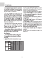
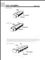
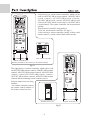
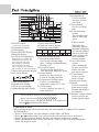
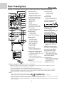
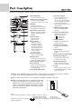
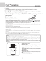
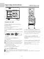
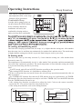
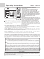
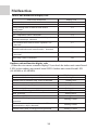
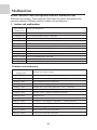
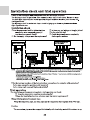
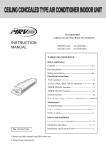
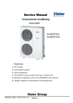
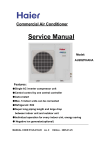
CEILING CONCEALED TYPEAIR CONDITIONER INDOOR UNIT
H-MRV
Ceiling Concealed Type Room Air Conditioner
INSTRUCTION
MANUAL
AE072FCAKA AE122FCAKA
AE092FCAKA AE142FCAKA
AE182FCAKA
AE212FCAKA
AE242FCAKA
Contents
Before Application
AE09~212FCAKA
Cautions
1-2
Part Description
3-8
Important Points of Safety
9-11
Operating Instructions
AUTO,COOL, DRY,HEAT Operation
TIME Operation
AE072FCAKA
12
13-14
Sleep Function
15
Health Function
16
Maintenance
Trouble Shooting
17-18
When Fault Occurs
19
Notice to Users
20
Indoor Unit Installation
AE242FCAKA
Installation Precautions
21-22
Installation Procedure
23-33
Malfunction
34-35
Installation Check and Trial Run
0010573331
Please read this manual carefully before use.
Please keep it attentively for future use.
36
Cautions
1
Cautions
Indoor DB C
WB C
Cooling
DB C
outdoor
WB C
DB C
Heating Indoor
WB C
outdoor DB C
WB C
Rated Maximum Minimum
27
32
18
19
23
14
35
43
-5
24
26
-20
27
15
14.5
--7
24
-15
6
18
--
2
D
AE072FCAKA
AE242FCAKA
AE092FCAKA , AE122FCAKA , AE142FCAKA , AE182FCAKA , AE212FCAKA have the Return air
box (see the following picture) when shipping from the factory and they are back-side return air. During
the installation, also can be changed to Down-side Return air according to the user's need.
AE09~212FCAKA
3
D
Left picture is a wired remote controller, which can be
used on AE072FCAKA(wired control), AE092FCAKA
(wired control), AE122FCAKA(wired control),
AE142FCAKA(wired control),AE182FCAKA(wired
control),AE212FCAKA(wired control), AE242FCAKA
(wired control). The remote controller can be purchased
extrally.
Wired remote Controller using method:
1.Use one wired remote controller. See fig (1)
2.Also can buy a remote controller extrally, realize wired
remote control + remote control dual control modes.
TEMP
ON
SWING
OFF
MODE
FAN
SLEEP
HEALTH FRESH
CLOCK
SET
TIMER
MODE
RESET
LIGHT LOCK
FAN
SWING
AUTO
TEMP
SET
*
ON
ROOM
OFF
HEALTH
CLOCK
SET
TIMER
SLEEP
C
FILTER RESET RESET
ON/OFF
B
A
Wire remote controlller
AUTO
Remote controlller (1)
Remote controlller is an accessory, to be ordered extrally
io
n
OFF
fig(1)
H
The right figure is a remote controller, which can be used
on AE072FCAKA(remote control), AE092FCAKA(remote
control), AE122FCAKA(remote control), AE142FCAKA
(remote control),AE182FCAKA(remote control),
AE212FCAKA(remote control), AE242FCAKA(remote
control) and the matching remote control receiver
TEMP
HEALTH
MODE
ON
OFF
FAN
SWING
TIMER
Remote control receiver using
method :
Use remote controller control
the remote control window of
the remote control receiver.
RESET CODE
LOCK
R
Remote receiver (2)
Remote controlller (2)
fig(2)
4
D
14 15 16 17 18
19
22.Setting button
Used to confirm
11
the time of timer
10
MODE FAN SWING
20
and clock
9
29
TEMP
23.Sleep
button
HEALTH
8
21
Used to set Sleep
SET
CLOCK
7
22
6
state
SLEEP
SET
TIMER
23
5
24.Time
Adjusting
24
FILTER RESET
button
4
25
Used to adjust the
26
3
ON/OFF
27
time of timer and
2
28
clock
1
30
25.Reset button
13.Sleep state display
1.ON/OFF button
When the wire
14.Network control display
Used to turn on/off unit
controller appears
15.Working mode display
2.Temperature display
abnormal condition,
Working
Auto
Cooling
Dehumidifying
Heating
Fan
3.Clock display
mode
operation operation operation
operation operation
use a sharp-pointed
4.Timer ON/OFF display
Wire
article to press this
controller
5.Humidity display
button to make the
6.Air filter cleaning display
16.Electric heating display
wire controller
When there is too much dust
17.Operation mode button
resume normal
collected on the air inlet, the
Used to set working mode:
26.Air Filter Reset
wire controller will show
Auto, Cooling, Dehumidifying,
button
this display to remind the
user to clean the air inlet.
Heating, Fan
After cleaning the
After cleaning and installation,
18.Fan speed button
*
air inlet, press this
just press the air filter reset button.
Used to set fan speed: Low
button, the unit
7.Super/Soft operation display
Fan, Med Fan, High Fan, Auto
can start to operate
8.Fan speed display
19.Swing button
27.Timer
button
Auto
Used to set Auto Swing or
Used to set the
Fixed air sending direction
mode of timer
Low Fan Med Fan High Fan Auto
20.Temperature Setting button
28.Lock state display
9.Auto Swing display
Used to set temperature,
29.Health
10.Health state display
temperature range: 16 C~30 C
Used to control the
11.Fresh air state display
21.Clock button
generating oxygen
12.Humidifying state display
Used to calibrate the time of
function and negative
timer and clock
ion-function
30.Remote
control window
Note:
1.This model does not have the following related
Used to receive the
display and function 5 6 7 9 11 12 14 16 26
remote control signal
13
12
AUTO
SUR
RESET
2.The outdoor unit no oxygen-bar function or no negative ion
unit no 10 19 healthl function display.
Calibration of clock
When turning on the unit for the first time, the clock should be calibrated. The method
of calibration is:
1.Press ìClockî button, the Clock display ìAMî ìPMî will flash.
2.Press or to adjust time. For each press, the time will increase or decrease 1
*minute. If depressing the button, the time will increase or decrease rapidly.
3.After confirming the time, press ìSetî button, ìAMî or ìPMî will stop flashing,the
clock will begin to work.
5
D
Remote LCD display contents and key name and each key function introduction
31
24
23
25
22
21
26
20
19
18
27
28
17
16
15
29
9
TEMP
ON
8
10
OFF
1
FAN
SWING
MODE
2
SLEEP
HEALTH FRESH
3
CLOCK
11
12
SET
4
13
TIMER
5
6
7
LIGHT LOCK
RESET
14
30
1.ON/OFF button
Used to turn on/off unit
Note: Wired remote
controller his key have compl
cooling running function.
2.Operation mode button
Used to set working mode:
Auto, Cooling,
Dehumidifying,
Heating, Fan
3.Health
Used to control the
generating oxygen function
and negative ion-function
4.Clock button
Used to calibrate the time
of timer and clock
5.Timer button
Used to set the
mode of timer
6.Time Adjusting button
7.Reset button
When the wire
controller appears
abnormal condition,
use a sharp-pointed
article to press this
button to make the
wire controller
resume normal
8.Swing button
Used to set Auto Swing or
Fixed air sending direction
MODE
FAN
SWING
AUTO
TEMP
SET
*
ON
ROOM
OFF
HEALTH
CLOCK
SET
TIMER
SLEEP
C
FILTER RESET RESET
ON/OFF
13.Setting button
Used to confirm
the time of timer
and clock
14.Lock button
Used to lock the operating
key and LCD contents
15.Timer ON/OFF display
16.Fan speed display
Auto
Low Fan Med Fan High Fan Auto
17.Battery energy display
18.Clock display
19.Auto Swing display
20.Humidifying state display
21.Sleep mode display
22.Working mode display
Working mode
Remote controller
Auto operation
Cooling operation
Dehumidifying
operation
Heating operation
Fan operation
23.Health state display
Display when the health
running
24.Electric heating display
25.Comfort running display
26.Fresh air state display
27.Signal launch display
9.Temperature Setting button
23.Temperature display
Used to set temperature,
Used to display the setting
temperature range: 16 C~30 C
temperature and room temp.
10.Fan speed button
29.Lock state display
Used to set fan speed: Low
Fan, Med Fan, High Fan, Auto 30.Light button
Used to realize control board
11.Sleep button
VFD light stable,light weaker,
12.Fresh air
light shut off etc.
Used to set fresh air function
31.Signal lauch head
Remote controller (Operation of remote controller)
Make sure that the remote controller is used within 7 meters from receiver window of the wire
controller and there are no obstructions in between.
The remote controller or wire controller should be handled with care.
When operating the remote controller in an area where electronically controlled lights are installed
or wireless handsets are used, move closer to the indoor unit as the function of the remote controller
might be affected by signals from this equipment.
Note:
1.This unit no the above function and display 8 12 17 19 20 24 25 26 30
2.The outdoor unit no oxygen-bar function ot no 3 23 functions fo non-negative ion unit.
3.When using remote controller, first point it to the receiving window of wire controller, and then operate
remote controller.A ìtickî tone will be uttered to indicate a right acceptance.
4.All the buttons except the sleeping button is no effective after wire controller received lock signal from
remote controller.
6
D
Remote LCD display contents and key name and each key function introduction
20
B
A
11
12
15
AUTO
16
ion
13
17
18
OFF
14
H
19
TEMP
2
ON
HEALTH
4
MODE
OFF
7
FAN
SWING
8
TIMER
6
21
RESETCODE
9
LOCK
10
1.ON/OFF button
Used to turn on/off unit
2.Temperature Setting button
Used to set temperature,
temperature range: 16 C~30 C
3.Health
Used to control the
generating oxygen function
and negative ion-function
4.Operation mode button
Used to set working mode:
Cooling, Dehumidifying,
Heating
5.Timer button
Used to set the
mode of timer
6.Reset button
When the remote
controller appears
abnormal condition,
use a sharp-pointed
article to press this
button to make the
wire controller
resume normal
7.Fan speed button
Used to set fan speed
8.Swing button
Used to set Auto Swing or
Fixed air sending direction
9.Time Adjusting button
10.Lock button
Press on time lock all the
key sand press another time
concel the lock.
11.Working mode display
12.Fan speed display
Used to display the fan
speed. After setting
"AUTO" function,air speed
can auto change according
to the temp. difference
between the room temp. and
setting temp.
13.Health running display
Used to display healthy
running.
14.Timer ON/OFF display
Display Timing mode.
"Blank" No Timing
"
" Timing off
"
" Timing on
15.Signal display
Sending out signal to the
remote receiver.
OFF
ON
16.Temperature display
Display the setting temp.
value.
17.Lock display
Display the key have been
locked.
18.Super/Soft operation display
19.Timing time display
Display timing open time
or timing close time
20.Signal launch head
Use to send signal to the
indoor unit receive window.
21.Code
Select remote control receive
code(H-MRV Remote cnotrol
type use A code)
Make sure that the remote controller is used within 7 meters from receiver window
of the wire controller and there are no obstructions in between.
The remote controller or wire controller should be handled with care.
When operating the remote controller in an area
where electronically controlled lights are
installed or wireless handsets are used, move
closer to the indoor unit as the function of the
remote controller might be affected by signals
from this equipment.
R
Note:
1.After change the battery, working condition resume as follows:
Working mode:cooling
Temp. 26 C
Timming mode: normal
Air speed: Auto
2.The units used in this manual no 8 18 functions. The health key can only control the
negative generator.
7
D
Clock set
When unit is started for the first time, clock should be adjusted as follows:
Press CLOCK button, "AM"or "PM" flashes.
Press or
to set correct time. Each press will increase or decrease 1min. If the
button is kept depressed, time will change quickly.
After time setting is confirmed, press SET, "AM "and "PM" stop flashing, while clock
starts working.
*
Battery loading
Batteries are fitted as follows:
*
*
*
Remove the battery compartment lid
Slightly press and disengage the battery compartment lid marked with ì
î and then hold
the remote controller by the upper section and then remove the battery compartment lid by
pressing in the direction of the arrow as shown in the figure above.
Loading the battery
Ensure that batteries are correctly placed in the compartment as required for positive and
negative terminals.
Replacing the battery compartment lid
The battery compartment lid is reinstalled in the reverse sequence.
Display review
Press the button to see if batteries are properly fitted. If no display appears, refit the batteries.
Caution:
If the remote controller does not operate as designed after fitting new batteries of the same
type, press the Reset button (marked ) with a pointed article.
Note:
It is recommended that the batteries be removed from the compartment if the remote
controller is not used for an extended period.
The remote controller is programmed for automatic test of operation mode after the
batteries are replaced. When the test is conducted, all icons will appear on the screen
and then disappear if the batteries are properly fitted.
When the display become weak, this display no power in the battery, please change the
battery.
5
2
4
3
1
1 .Emergency switch
2 .Power lamp
After open the unit, this lamp bright when the
unite enter health running, the lamp change from
orange to blue lamp.
3 .Timing lamp
When the unit been setting Timing running, this
lamp bright.
4 .Running lamp
When the compressor working, this lamp bright.
5 .Indoor temp. sensor
Test the room temperature.
R
8
Important Points of Safety
The following four important points of safety and suggestions should be paid great attention:
!
Warning:
Misuse may cause fatal result such as death or serious injury etc.
!
Attention:
Misuse may cause human injury or damage of machine, in some case
fatal results.
Content marked with this ìforbiddenî sign should be absolutely forbidden, otherwise may cause damage of machine and human injury of the
user.
Content marked with this ìcompulsoryî sign should be executed compulsively, otherwise may cause damage of machine and human injury of
the user.
:
!
:
Comply with the following important points of safety.
Put these important points of attention and suggestions nearby and convenient for reference in need.
Hand over this instruction manual to new user if you resell this machine.
!
Warning
Warning for installation
Entrusted Installation
Installation of the machine should
be entrusted to certified person of
after service. Unauthorized installation may cause water leakage,
electric shock or fire hazard for
improper operation.
The power supply must be fitted with
earth line to ensure valid earthing of
the air-conditioner. No or incomplete
earthing connection may cause the
risk of electric shock.
!
Test run
After indoor units are installed,all
cassettes hinded models should be
tested.when the units are confirmed
to be normal,other fitments can be
installed.
To prevent leakage of refrigerant,
let certified person of after service
do it.
Leakage of refrigerant over certain
consistence may result in shortage
of oxygen. Enough precautions
MUST be done to avoid oxygen
shortage in case of refrigerant leaking if the room where the airconditioner is installed is small.
!
9
!
!
Important Points of Safety
! Warning
Warning for use
Avoid your body being blown
directly by cold wind for long
period, otherwise your health
may be affected.
If something abnormal (e.g.: burnt
smell etc.) occurs, stop running the
machine, shut down the manual
power switch and contact after
service. Continuous operation in
disorder may cause fire hazard or
electric shock etc.
Donít extend your fingers or
any other article into the inlet
or outlet during operation of
the machine for touching revolving fans may cause human
injury or damage of machine.
!
Warning for move and repair
When you have to disassemble
and reinstall the machine, entrust
it to after service. Improper installation may cause fire hazard,
electric shock or damage of machine.
!
Unauthorized alteration or repair
work is strictly forbidden. Improper alteration or maintenance
may cause fire hazard, electric
shock or water leakage. Repair
work should be entrusted to certified person of after service.
! Attention
Attention points for installation
Ensure the drainage hose work
normally during installation.
Improper installation of drainage
can cause water leakage and
damp articles.
!
Ensure electric leakage breaker
being installed. Electric leakage
breaker MUST be installed,
otherwise electric shock may be
caused.
!
DO NOT install the machine in
place where flammable gas
releases easily to avoid fire
hazard.
If the power supply cord is
damaged, call a certified
electrician of the manufacturer
or other maintenance department
to replace it.
10
Important Points of Safety
! Attention
* Ensure ventilation of the room
if the machine is used with
burning facilities. Deficient
ventilation can cause oxygen
shortage.
* DONíT lay any burning facilities
in place where winds produced by
the machine can reach. Incomplete
combustion of burning facility may
be caused otherwise.
* Check whether installation
bench of the machine is
damaged after a long period
of use. Machine on damaged
bench may fall down and cause
human injury or other damage.
* DONíT clean the machine with
water. Electric shock may occur
otherwise.
Attention points for use
* In place where winds produced
by the machine can reach, donít
lay any animals or plants which
may be hurt otherwise.
* Donít put vases containing water
or other else on the unit assembly.
Otherwise, the machine may be
immersed internally and result in
bad electric insulation causing
electric shock.
* DONíT put flammable spray
articles nearby or spray them to
the machine. Fire hazard may
occur otherwise.
* DONíT operate switch with wet
hand. Electric shock may occur
otherwise.
* Stop operation and shut down
manual power switch before
cleaning and maintenance.
* The is machine CANNOT be
used for the purpose of preserving food, animals, plants,
precision instruments and
artwork etc., which may be
destroyed otherwise.
* The power supply MUST be of
rated voltage and connected with
special electrical supply circuit.
* DONíT replace fuse with material other than fuse of proper
capacity. Replacing fuse with
metal wire or copper etc. can
cause fire hazard or other faults.
11
Operating Instructions
AUTO RUN, COOL,HEAT and DRY operation
Recommendations
Use COOL in summer.
Use HEAT in winter.
Use DRY in spring,autumn and in damp climate.
TEMP
FAN
MODE
AUTO
2
SWING
ON
HEALTH
TEMP
OFF
SWING
4
FAN
5
MODE
CLOCK
SET
SLEEP
SET
3
HEALTH FRESH
TIMER
SLEEP
CLOCK
*
FILTER RESET RESET
SET
TIMER
AM
5
ON/OFF
RESET
1
(1) Unit start
Press FAN button. For each press,
fan speed changes as follows:
Press ON/OFF button, unit starts.
Previous operation status appears on display
(Not Timer setting). Power indicator lights up.
AUTO
Wire controller
LOW
(2) Select operation mode
Press MODE button. For each press, operation mode
changes as follows:
COOL
DRY
HEAT
FAN
MID
HIGH
AUTO
Remote controller
LOW
AUTO
LIGHT LOCK
MID
A
U
T
O
HIGH
AUTO
Unit runs at the speed displayed on LCD.In HEAT
mode, warm air will blow out after a short period
of time due to cold-draft prevention function.
In DRY mode, when room temp. becomes 2 C higher
than temp. setting, unit will run intermittently at
LOW speed regardless of FAN setting.
Unit will run in operation mode displayed on LCD.
Stop display at your desired mode.
(3) Select temp. setting
Press TEMP button
Every time the button is pressed, temp. setting
increases 1 C.
If button is kept depressed, temp.setting will
increase quickly.
Every time the button is pressed, temp. setting
decreases 1 C.
If button is kept depressed, temp. setting will
decrease quickly.
(5) Unit stop
Press ON/OFF button.
Only time and room temp remains on LCD.
All indicators go out.
Vertical flap closes automatically.
Hints
Wire controller can memorize each operation status.
When starting it next time, just press ON/OFF button
and unit will run in previous status.
Unit will start running to reach the temp. setting
on LCD.
(4) Fan speed selection
Auto running: During the Auto running mode, air conditioning running and can auto-select the cooling, heating, fan
mode according to the room temperature.
Fan running: The AC only have air supply running no cooling and heating running at the condition, AC can't have auto
air supply running, and can't display the setting temperature value on the LCD.
During the heating running, after start the AC, in order to prevent cooled air, AC can stop for a while before send heat
air.
During the dehumification running, when the room temp. setting temp. , not setting condition according to the air speed.
12
Operating Instructions
MODE
FAN
TEMP
SWING
HEALTH
CLOCK
SET
TEMP
2 TIMER
SET
TIMER Operation
SLEEP
4
ON
*
AM
OFF
3
AM
FAN
SWING
FILTER RESET RESET
ON
1
MODE
SLEEP
HEALTH FRESH
ON/OFF
CLOCK
1
2
SET
TIMER
4
3
RESET
LIGHT LOCK
Set Clock correctly before starting Timer operation.
You can let unit start or stop automatically at following time: Before
you wake up in the morning, or get back from outside or after you
fall asleep at night.
TIMER ON/OFF
(1)After unit start, select your desired
operation mode.
Operation mode will be displayed on LCD.
Power indicator lights up.
(2)TIMER mode selection
Press TIMER button to change TIMER mode.
Every time the button is pressed, display changes
as follows:
ON
ON
OFF
blank
OFF
Select your desired TIMER mode (ON or OFF)
To cancel TIMER mode
(3)Timer setting
Press TIME
button.
Every time the button is pressed, time increases 10min.
If button is kept depressed, time will change quickly.
Every time the button is pressed, time decreases 10min.
If button is kept depressed, time will change quickly.
Time will be shown on LCD. It can be adjusted within
24hours.
(4)Confirming your setting
After setting correct time, press SET button to confirm
"ON" or "OFF" stops flashing.
Time displayed: Unit starts or stops at x hour x min (ON
or OFF).
Timer mode indicator lights up.
Just press TIMER button several times until TIMER mode disappears.
According to the seting timing open, close sequence, can realize first open then colse the unit or
first close then open the unit.
Hints:
Wire controller possesses memory function, when use TIMER mode next time, just
press SET button after mode selecting if timer setting is the same as previous one.
Wire remote controller or remote controller can memorize each working condition. Next
time open the unit, only need to press the ON/OFF key, the AC can work according to
last time working condition.(Timing, Sleeping and Swing mode not included.)
From Timing close to timing open, can setting sleep mode.
Please close health function first before setting Timer, then you can do the TIMER ON
operation.Please do not use the health function when in TIMER ON state.
13
Operating Instructions
FAN
MODE
SWING
TEMP
CLOCK
SET
HEALTH
3
2 TIMER
SET
TEMP
SLEEP
*
ON
OFF
AM
TIMER Operation
ON
6
OFF
1FAN
SWING
4
5
FILTER RESET RESET
MODE
SLEEP
PM
HEALTH FRESH
3
ON/OFF
CLOCK
SET
2
1
TIMER
6
4
TIMER ON-OFF
RESET
5
LIGHT LOCK
(1)After unit start, select your desired
operation mode
Operation mode will be displayed on LCD.
Power indicator lights up.
(2) Press TIMER button to change TIMER
mode
(4) Time confirming for TIMER ON
Every time the button is pressed, display changes as follows:
After time setting, press TIMER button to confirm.
"ON" stops blinking, While "OFF" starts blinking.
ON
ON
Select
OFF
blank
Time displayed: Unit starts at Xhour X min.
OFF
(5)Time setting for TIMER OFF
ON
OFF .
Follow the same procedures in "Time setting for
TIMER ON".
(3)Time setting for TIMER ON
Press TIME button.
Every time the button is pressed, time increases 10min.
If button is kept depressed, time will change quickly.
Every time the button is pressed, time decreases 10min.
If button is kept depressed, time will change quickly.
Time will be shown on LCD.
It can be adjusted within 24hours.
AM refers to morning and PM to afternoon.
(6)Time confirming for TIMER OFF
After time setting, press SET button to confirm
"OFF" stops flashing.
Time displayed: Unit stops at X hour X min.
To cancel TIMER mode
Just press TIMER button several times until TIMER mode disappears.
According to the Time setting sequence of TIMER ON or TIMER OFF, either Start-Stop or Stop-Start can
be achieved.
14
Operating Instructions
Sleep Function
Note: Before using this function,
must adjust the clock, or the sleep
function will be disordered.
MODE
FAN
SWING
TEMP
Comfortable Sleep
ON
TEMP
At night, before going to bed you
can press down the SLEEP button
on the controller and the airconditioner will run by the
comfortable sleeping mode to
make you sleep more comfortable.
OFF
HEALTH
SWING
FAN
MODE
CLOCK
SET
TIMER
SLEEP
HEALTH FRESH
CLOCK
SET
SET
TIMER
*
FILTER RESET RESET
OFF
AM
SLEEP
AM
RESET
LIGHT LOCK
ON/OFF
In cooling, dehumidifying mode
One hour after sleeping operation start, the temp. is 1 C higher than the setting one. After another
hour the temp. rises 1 C and then run continuously for another 6hrs' and then close. The actual temp.
is higher than the setting one which is to prevent from being too cool to your sleep.
In heating mode
One hour after start up, the temp. decrease 2 C lower than the setting one. After another hour
decrease by more 2 C .
The temperature will automatically rise by 1 C after another 3hrs' operation, and then automatically
close after 3hrs' continuous operation. The actral temperature is lower than the setting one which
is to prevent from being too hot to your sleep.
Note:
In AUTO mode, unit will run in SLEEP function according to the operation mode.
After setting SLEEP function, it is forbidden to calibrate clock.
If the set sleep-time does not reach 8 hours, the unit will stop operation automatically after set
time is complete.
Set "TIMER-OFF" function first, then set SLEEP, and the sleep-set is performance; set TIMERON function first, the sleep function can only be set before TIMER-ON; if set theSLEEP function
first, the TIMER function can not be set.
After setting sleep function, not allowed to adjust the clock. Can't use the remote controller
operate the AC. If so, please cancel the sleep function first.
After setting sleep function, can't set the timing function.
SETTING T
SLEEP RUN BEGINS
SHUT DOWN
1 hr
SLEEP RUN STOPS
about 6 hrs
decrease 2 C
1 hr
1 hr
decreases 2 C
increase 1 C
about 3 hrs
3 hrs
1 hr
increase1 C
increase 1 C
SHUT DOWN
SETTING T
SLEEP RUN BEGINS
SLEEP RUN STOPS
Cooling mode
Heat mode
15
Operating Instructions
MODE
FAN
SWING
TEMP
ON
TEMP
HEALTH
SWING
OFF
MODE
CLOCK
FAN
SLEEP
SET
HEALTH FRESH
SET
TIMER
SLEEP
*
SET
TIMER
FILTER RESET RESET
OFF
AM
CLOCK
AM
RESET
LIGHT LOCK
Health Function
1.How to use the health function (only for units
with this function)
After set the right function mode, press health button,
remote controller or wire controller displays ì î,
oxygen pump or negative ion generator starts up to apply
oxygen or negative ion to indoor unit. Press the button
again,the sign ì î disappeared and negative ion generator
stops working. After all health function of the indoor unit
being fully canceled, oxygen pump stopped.
CAUTION:
When the temperature of the outdoor unit is lower than 4 C,
oxygen pump is automatically stopped, if press health button
just then, oxygen pump could not start up. But if the air
conditioner has the negative ion function simultaneous,
On the "Health" mode, if you want to setting
when press the health button, negative ion function could
timing open mode, should close the health
still be operated. When the temperature of the outdoor unit
first: On the timing open mode, please don't
is higher than 6 C, oxygen pump could automatically resume
use health function.
to oxygen-make function.
Power Failure Compensation (to be applied for a necessary situation) :
After the power failure compensation is set, if power failure suddenly occurs while the air conditioner is working, it
will resume the previous working state when the power is supplied again.
ON/OFF
Setting Method: When the remote controller is on (excluding timer mode and fan mode),
press the "Sleeping" button on the remote controller 10 times within 5 seconds, and after the buzzer rings 4 times,
the air conditioner will enter the state of power failure compensation.
Cancel Method: Press the "Sleeping" button on the remote controller 10 times within 5
seconds, and after the buzzer rings 2 timer, the power failure compensation mode will be cancelled.
Notes: When a power failure suddenly occurs during the air conditioner is working after the power failure
compensation is set, if the air conditioner will not be used for a long time, please cut off the power supply to prevent
its operation from being resumed after the power is supplied again, or press the "Switch On/Off" button after the
power comes again.If the controller no sleep key ,use the "swing" key instead the "sleeping" on setting the auto
restart function.
Concerning MRV Auto Restart function for H-MRV models
Haier Auto Restart function when the unit power drops down suddenly, the unit microprocessor will store the previous
working condition and when the power is on again, the unit will run as this memory.
Auto Restart function is designed basically on the MRV whole system, but it is suitable for each indoor unit individually.
If some of indoor units power cut down, but the outdoor unit and the other indoor units still work, maybe problems
will happen such as freezing at cooling mode and overload protection at heating mode on those indoor units without power.
Reason
When one or some indoor units power drops down and the other indoor units are still work, the indoor units without
the power, will keep the previous working condition before the power is off. And expansion valve keeps open at a kind of
opening rate condition as the previous requirement, so there is refrigerant flowing in the exchanger, but the indoor fan stops
working. If the units work at cooling mode, the indoor units without the power will maybe make freezing. If the unit works
at heating mode, maybe the outdoor unit compressor will stop because of the pressure or temperature protection. This is
our design basically on Auto Restart function currently.
Haier, Herewith, solemnly informs our customers, installers, distributors, etc. when making installation, please make sure
when the power is shut down whether artificially or accidentally, the whole system including outdoor unit and all the
indoor units must be off. If you do not make the installation as our indication, Haier will not be responsible for any problem
resulting from this.
User Caution
About the remote cnotrol operation, above only take wired remote controller and remote controller (1) as a
example about the remote controller (2) and remote receiver use method, it is the same remote controller (1) ,
please use refer to above method.
No sleep function when use remote (2) and remote receiver.
16
Trouble Shooting
The following cases are not troubles.
Water flow sound is heard.
During operation, the air conditioner may
sometimes exhibit a sound of "clatter" or
"rumble". This is the common sound of
refrigerant flow but not a trouble.
"Hua-Hua"
A sound of "Pi-Pa" is generated.
This is caused by the thermal expansion
or cold shrinkage of plastics.
Smells are given off.
Sometimes there are smells in the air flow
from the indoor unit. This is caused by the
smell of cigarettes or paint coatings inside
the unit.
During operation, mist or steam are
blown out.
During COOL or DRY operation, the unit
may blow out a thin mist. This is the condensate water mist caused by sudden cooling of the indoor air blown out from the
indoor unit.
During COOL operation, it automatically
changes to FAN mode.
In order to prevent frost accumulation on
the heat exchanger in the indoor unit,
sometimes it will automatically transfers
to FAN mode, but soon will return to
COOL mode.
The system couldnt be re-started immediately
after turning off.The unit can't start?
This is due to the systems self-protection
function, which prevents it from restarting
in 3 min after stops.
Please wait
for 3 min.
18
Trouble Shooting
During DRY operation, there is no air
sent out or fan speed cant be changed.
In HEAT mode, the outdoor unit
generates water or steam.
This occurs during removal of the frost
(in defrosting operation) on the radiator
of outdoor unit.
Defrost operation
In HEAT mode, the indoor fan still
keeps running even the unit operation
stops.
After the unit stops, the indoor fan will
continue to run for a while to eliminate
residual heat.
Before asking for after-service to an authorized service center,
please check your air
conditioner for the following items
The system couldnt start
Is power on/off switched on?
Is the power supply line
normal?
Power
failure?
Is current leakage breaker
triggered?
ON
OFF
Please do immediately
cut off power supply and
contact the authorized
service center.
The power on/off switch is
not at position of "ON".
18
When Fault Occurs
Poor cooling or heating
Is the operation controller
adjusted as required?
Is there any door or window
Are there any obstructs
before the air inlet or outlet? left open?
Poor cooling
Is there any other heat
source in the room?
Is there any direct sunlight
into the room?
Are there too many people
in the room?
If, after the above checks and the corresponding corrective actions, the system remains
abnormal operation, or the following facts appear, please turn off the air conditioner and
then contact the local authorized service center.
Frequent open of fuse or breaker.
There is water leakage during COOL or DRY operation.
The operation is abnormal or abnormal sound is heard.
19
Notice to Users
Notice to users
To ensure proper operation of the system, the user shall follow this instruction manual
to install the unit.
When handling the air conditioner, please be care not to scratch the case surface.
This instruction manual describes the installation method aided with the installation
tools specified by manufacturer .
The maximum length of connection pipe is 50 m, and the maximum difference between
levels of indoor unit and outdoor unit shall be 30 m.
Please keep the installation instruction manual well for reference in maintenance or
changing installation position.
After installed, please follow the operational instruction manual to use the air conditioner
properly.
Information about application
Adjust your desired air flow direction
Avoid direct sunlight and gas flow
Keep appropriate room temperature
Too cool or too warm wont benefit
to your health, but causes an increased energy consumption.
Effectively use the timer Using
TIMER mode you can enjoy a
comfortable room temperature
when wake up or come back home.
Maximum
temperature
Caution: After installation, please confirm no refrigerant leaks.
20
Installation Precautions
Before installing, do read this "Safety precautions" carefully to guarantee the proper installation.
The below attentive matters are divided into" ! Warning" " and " ! Note" two parts. When the
wrong installation occur, it is very possible death and severe injury and other serious accidents will
happen. For those items are listed in" ! Warning" part. But even the items listed in " ! Note"
part can also cause serious accidents. Above all, both the two parts are very important contents
related to safety, so they must be obeyed.
After finishing the installation work, do test run to verify everything is normal. After that please
explain the using and maintenance methods to the user. Additionally, give this installation manual
and operation manual to the user and ask them to keep it properly.
!
Warning
The distributing shop, where you bought the air conditioner, or the specified shops shall do the
installation work. If you do the installation work by yourself, the improper installation will cause
water leakage, electric shock fire and other accidents.
The installation work shall be in line with what the installation manual specified. If installation
is not proper, water leakage, electric shock, fire and other accidents will occur.
Install the air conditioner to a place where can definitely stand its weight. Places not firm enough
will cause drop down of unit resulting in body hurt.
The installation work shall be preventive to typhoon and earthquake. If the installation work is
not met with the requirements, overturn of the unit will occur resulting in accidents.
The wiring work shall be done by a qualified person and referred to the " technical standard of
electric equipment" , "indoor wiring regulation" and what the manual specified. Do use
special circuit. If the capacity of the circuit is not enough or bad work, electric shock, fire and other
accidents will happen.
Using the specified cable to do wiring work and connecting firmly and properly. Fix the connecting
part of the terminals to prevent it from the external force.Improper connection and fixing will cause
heating and fire etc. accidents.
Wiring shall be kept in correct shape avoiding extrusion. After installation, the electric box cover
and the external panel shall not nip the wire. Improper installation will cause heating and fire etc.
accidents.
When setting or moving the air conditioner do not let the air and things alike get into the
refrigeration system except the specified refrigerant (R22). If air and other things enter, abnormal high pressure will occur, which easily cause break and body injuries etc. Accidents.
When installing, do use the accessories or specified parts. If not using the parts specified by our
company, water leakage, electric shock, fire and refrigerant leakage will occur.
Do not lead the drainpipe to drain where the sulfur gas may be involved. Otherwise, the poisonous
gas will enter into the indoor.
During installation, if refrigerant leakage occurs, do the ventilation work immediately. As soon as
the refrigerant gas meets fire, poisonous gas will be produce. If the refrigerant gas enters into room
and meet the air blowing heater, heater or stove etc. fire source, the poisonous gas may be produced.
After installation, confirm there is no leakage of refrigerant.
Do not install the unit in a place where the combustible gas may be leaked. In any case the
combustible gas leaks and accumulated around the unit, fire accident will occur.
Do heat insulation work to the refrigerant gas pipes and liquid pipes to reach the purpose of heat
preservation. If the heat insulation measure is not sufficient, water generated by condensing dew
will drip leading to wet the floor and indoor articles.
!
Note
Do grounding work.Do not connect the grounding wire to gas pipe,tap,lighting rod or telephone
line.Improper grounding will cause electric shock.
After electric installation,power on them to do electric leakage test.
21
Installation Precautions
! Attention
This description does not address to all possible cases. For new requirement and query, please
consult the regional sales center of Haier Air Conditioner General Co., Ltd.
! Warning
This instruction manual must be read carefully before beginning of installation, improper installation may cause accidents and thus bring about machine damage and personal casualty.
Installing tools
1. Screw driver
6. Pipe cutter
10. Leakage detector or soap water
2. Hacksaw
7. Pipe expander
11. Measuring tape
3. Driller of 70mm diameter
8. Knife
12. Scraper
4. Spanner (diameter 17, 27mm)
9. Pinchers
13. Refrigeration oil
5. Spanner (14, 17, 19, 27mm)
Electrical requirements
The power supply shall be connected from the outdoor side. (For models with electric-aided
heating function, the power supply to the indoor unit shall be connected at the indoor side
The power cord size is 3 G(1.0-1.5)mm2, type of H05RN-F).
A separate power circuit shall be supplied and connected by a qualified electrician according
to the wiring rules specified in the corresponding national standard.
A current leakage breaker must be installed.
The connection method of power cord is " Y " type. If the power flexible cord is damaged, it
shall be replaced by the manufacturer or its service department or similar qualified technician
so as to avoid risks.
Power cord plug: L should be connected to the live wire, N should be connected to the neutral
wire and to the ground wire.
Connection wire size: 3 G (1.0-1.5) mm2, type of H05RN-F.
Signal transmission wire size:H05RN-F 2 x (0.75-1.5) mm2 (shielded wire).
Power cord, connection wire and signal wire shall be provided by the user.
Indoor unit
1. Select suitable places the outlet air can be sent to the
entire room, and convenient to lay out the connection
pipe, connection wire and the drainage pipe to outdoor.
2. The ceiling structure must be strong enough to support
the unit weight.
3. The connecting pipe, drain pipe and connection wire
shall be able to go though the building wall to connect
Fig 1
between the indoor and outdoor units.
4. The connecting pipe between the indoor and outdoor
units as well as the drain pipe shall be as short as possible. (See Figure 1)
5. If its necessary to adjust the filling amount of the refrigerant, please refer to the installation
manual attached with the outdoor unit.
6. The connecting flange should be provided by the user himself.
7. The indoor unit have 2 drainage outlet, one outlet be jamedwith rubber cap, during installation
only use another outlet (In/Out liquid pipe side). When necessary, use the two outlet at the
same time.
8. Not place the TV., equipment, facility, piano etc, expensive goods below the AC, prevent the
water dropping down from the AC and lead to damage to the goods.
22
Installation Procedure
After selecting the unit installation location, proceed the following steps:
1. Drill a hole in the wall and insert the connecting pipe and wire through a PVC wall-through tube
purchased locally. The wall hole shall be with a outward down slope of at least 1/100. (See
Figure 2)
2. Before drilling check that there is no pipe or reinforcing bar just behind the drilling position.
Drilling shall avoid at positions with electric wire or pipe.
3. Mount the unit on a strong and horizontal building roof. If the base is not firm, it will cause
noise, vibration or leakage (see Figure 6).
4. Support the unit firmly.
5. Change the form of the connection pipe, connection wire and drain pipe so that they can go
through the wall hole easily.
Figure showing installation dimensions: (unit:mm)
b
c
d
e
f
g
i
AE092FCAKA 615
648
452
225
55
125
225
100
AE122FCAKA
AE142FCAKA
770
804
452
225
55
125
225
100
AE182FCAKA
AE212FCAKA 990
1024
452
225
55
125
225
100
a
Model
Fig 2
c
b
i
e
f
d
a
g
223
223
500
9
124
AE072FCAKA
AE242FCAKA
Notes
1.For electrical heating unit, the air outlet not allowed directly connecting with canvas
etc. easy catching fire goods.
2.This series' indoor unit are all middle static pressure(30 Pa external static pressure ).
3.An access port must be provided during installation of indoor unit for maintenance.
23
Installation Procedure
Installation of indoor unit
When installing the ceiling concealed type indoor unit, a specially designed return air
bellows shall be installed, as shown in Figure 3, Figure 4.
Figure 3
Installing building roof
*0.5m or*5m
A
Ceiling
Unit
Air supply
Air outlet duct
Return air bellows
Return air
Detail A
Figure 4
Air outlet grille
Air supply
No obstacles
within 1 m
Return air bellows
Unit
Return air
Each air return and supply duct should fix to the floor precast slab by using an iron stand. Use glue to
seal the interface closely. Recommend the distance between the air return duct and the wall is more than
150mm.
The distance between air duct outlet and air conditioner outlet is according to the length of actually installed
air duct and in service behavior of the static pressure terminal: Installation sketch map for long and short air
duct is showed below, when connect to short air duct, using low static terminal (terminal color is write), the
distance between air duct outlet and air conditioner outlet is no more than 0.5m; when connect to long air duct,
using middle static terminal (terminal color is red), the distance between air duct outlet and air conditioner outlet
could be within 5m at this point.
Figure 5
sling dog
drain piping
air return duct
transition air outlet
air return shutter air duct duct
joint of air diffuser
air diffuser
Drain piping of condensed water should keep a downhill grade of 1% or more. Use insulating pipe to cover
the drain piping of condensed water to keep warmth.
As figure shown, suspend and install the unit.
Figure 6
M8 broad foundation bolt
M8 suspension screw
Unit
M8 broad lock ring
M8 nut
Figure 5
24
Installation Procedure
Installation of indoor unit
Installation for air duct of indoor unit
1. Installation for air supply duct
This type of unit uses circular air duct with its caliber of 180mm.
An additional transitive air duct is necessary for the circular air duct to connect to the air
supply inlet. It should be also connected to its respective air diffuser separately. See
Fig.1. Adjust the wind speed of each air diffuser outlet to keep in line on the whole, so
as to meet a demand of the air conditioner in the room.
Indoor unit
flexible joint
or static pressure box
transitive air duct
circular air duct
joint of air diffuser
air diffuser
Fig1: Duct connected
2. Installation for air return duct
Use rivets to connect the air return duct to the air return inlet of the indoor unit. The
other end connects to the air return shutter. as shown in Fig.2.
air return
shutter
air return
duct
indoor unit
rivet
Fig2: Duct return connected
3. Air duct insulation
Insulation layer is needed for air supply and return duct. First, paste a glue nail to the
air duct, and then attach the insulation cotton that has a tinfoil layer and use the glue
nail cover to fix. Finally, seal the air duct interface with tinfoil adhesive tape closely.
as shown in Fig3.
galvanized
board
insulating
fabric
tinfoil
glue nail cover adhesive tape
glue nail
Fig3
25
Installation Procedure
Installation of indoor unit
Installing the suspension screw:
Use M8 or M10 suspension screws (4, prepared in the field) (when the suspension screw
height exceeds 0.9 m, M10 size is the only choice). These screws shall be installed as
follows with space adapting to air conditioner overall dimensions according to the original
building structures.
Wooden structure
A square wood shall be supported by the beams and then set the suspension screws.
Square wood
Beam
Suspension
screw
New concrete slab
To set with embedded parts, foundation bolts etc.
Iron reinforcement
Foundation bolt
Knife embedded part
Guide plate embedded part
Pipe suspension foundation bolt
Original concrete slab
Use hole hinge, hole plunger or hole bolt.
Steel reinforcement structure
Use steel angle or new support steel angle directly.
Hanging bolt
Suspension screw
Support steel angle
Hanging of the indoor unit
l Fasten the nut on the suspension screw and then hang the suspension screw in the T
slot of the suspension part of the unit.
l Aided with a level meter, adjust level of the unit within 5 mm.
26
Installation Procedure
Installation of remote controller
Upper cover of wire
controller
1. Remove upper cover of wire controller
Remove upper part of wire controller
by press.
Lower cover of wire
controller
PCB is mounted on lower part of wire
controller, be careful not to damage it.
2. Install the wired remote controller
Please drill two holes on the wall according to the
back cover screw hole position of the wire remote
controller, then strike the wood block to the holes
respectively, then align the 2 screw hole of the wire
controller back cover to the wood block, fasten the
wire reote controller to the wall use wood screws.
3. Switch setting
The switchs setting as follows:1.ON 2.OFF 3.ON 4.OFF
Switch button
Screw hole
Note
Try as far as possible a flat surface for installation.
Don't use excessive force when tightening screws,
or lower part might got deformed.
4. Connecting method as the following chart
No Symbol
colour
contents
1
A
White or Green
12V
2
B
Red
Gnd
3
C
Yellow
COM
4
D
Back cover of the wire
controller
Use shielede wires for telecommunication
between wire controller and indoor unit;
indoor unit and outdoor unit. Ground the
shield on one side.
Otherwise misoperation because of noise
may occur.
Signal wire is self-provided by user.
Shielded wire
ground
5. Replace the upper cover of wire controller
Be careful not to hold down the wiring.
Hint 1. Power supply switch and signal wire should be prepaired by the user.
2. Don't touch PCB with hand.
27
Installation Procedure
Installating the Reciever and MP3 equipment MP3
Installation of receive display
Because of the temperature sensitive device, do not install the receive display at straight
sunlight place, either in front of air outlet grill, for it is effected greatly from cool air and
heat air, the receive display is at least 20mm distance to the air outlet grill.
Since there is light sensitive device which receives wireless remote signal, so do not installed
behind the window curtain or other obstacles, in order not to obstruct the signal.
Must fix the remote control wire far from strong electricity (such as the wiring of electric
light, air conditioner, etc.) and weak electricity (such as the wiring of telephone, interphone,
etc.).
2.Place the panel onto the fixed frame, pay
attention that the four claws must be placed
into the corresponding four poles on the frame
1.Fix the receive display with screws
on the selected place
Connecting wiring method of receiver :
Refer the indoor unit wiring diagram .
safety cautions see the electrical wiring part .
28
Installation Procedure
Drain pipe
! Caution
In order to drain water normally, the drain pipe shall be processed as specified in
the installation manual and shall be thermal insulated to avoid dew generation.
Improper hose connection may cause indoor water leakage.
Requirements
The indoor drain pipe shall be thermal insulated.
The connection part between the drain pipe and the indoor unit shall be insulated so as to
prevent dew generation.
The drain pipe shall be slant downwards (greater than 1/100). The middle part shall not be
of S type elbow, otherwise abnormal sound will be produced.
The horizontal length of the drain pipe shall be less than 20 m. In case of long pipe, supports shall be provided every 1.5 ñ 2m to prevent wavy form.
Central piping shall be laid out according to the following figure.
Take care not to apply external force onto the drain pipe connection part.
1.5m~2m
Support
Down slope
Insulation
(supplied by the user) above 1/100
S type elbow
Wall
To the largest (app. 10cm)
Outside
VP30
Slant
Down slope above 1/100
Pipe and insulation material
Drain pipe (supplied
by the user)
Pipe
Rigid PVC pipe VP31.5mm (internal diameter)
Insulation Foamed PE with thickness above 7mm
Hose
Drain pipe size: ÿ19.05mm2 (3/4") PVC pipe
The hose is used for adjusting the off-center and angle of the rigid PVC pipe.
Directly stretch the hose to install without making any deformation.
The soft end of the hose must be fastened with a hose clamp.
Please apply the hose on horizontal part
Hose
Hose clamp
sulation treatment:
Wrap the hose and its clamp until to the
indoor unit without any clearance with
insulating material, as shown in the figure.
Drain confirmation
Subsidiary insulation
Insulation
Rigid PVC pipe
During trial run, check that there is no leakage at the pipe connection part during water
draining even in winter.
29
Installation Procedure
Refrigerant piping
Allowable pipe length and drop
These parameters differ according to the outdoor unit. See the instruction manual attached
with the outdoor unit for details.
Pipe material and size
Pipe material Phosphorus deoxidized copper seamless pipe (TP2M) for air conditioner
AE182FCAKA
AE072FCAKA AE122FCAKA
Model
AE212FCAKA
AE092FCAKA AE142FCAKA
AE242FCAKA
Gas side
Pipe size
ÿ9.52
ÿ12.70
ÿ15.88
(mm)
Liquid side
ÿ6.35
ÿ6.35
ÿ9.52
Supplementary refrigerant
The refrigerant supplementation shall be as specified in the installation instructions
attached with the outdoor unit. The added refrigerant shall be R22.
The adding procedure shall be aided with a measuring meter
for a specified amount of supplemented refrigerant
A
Requirement
Overfilling or underfilling of refrigerant will cause compressor
fault. The amount of the added refrigerant shall be as specified
in the instructions.
Connection of refrigerant pipe
Pipe expander
1. Pipe cutting 2. Removing burrs
Conduct flared connection work to
connect all refrigerant pipes.
Pipe cutting and expanding
If the pipe is too long or the flare is damaged,
it needs to be cut or expanded.
3.Insertion nut 4. Pipe expansion
Pipe expansion dimensions as follows:
Pipe diameter ÿ Size A (mm)
6.35 mm (1/4")
9.52 mm (3/8")
12.7 mm (1/2")
15.88 mm (5/8")
0.8 ~ 1.5
1.0 ~ 1.8
1.2 ~ 2.0
1.4 ~2.2
Incorrect
Correct
Slope Damage Bur Partial Overlong
The connection of indoor unit pipes must use double spanners.
The installing torque shall be as given in the following table.
Connecting pipe
O.D.(mm)
ÿ6.35
ÿ9.52
ÿ12.70
ÿ15.88
Installing torque
(N-m)
11.8 (1.2kgf-m)
24.5 (2.5kgf-m)
49.0 (5.0 kgf-m)
78.4 (8.0 kgf-m)
Increased installing
torque (N-m)
13.7 (1.4 kgf-m)
29.4 (3.0 kgf-m)
53.9 (5.5 kgf-m)
98.0 (10.0 kgf-m)
30
Double-spanner
operation
Installation Procedure
Refrigerant piping
Vacuum pumping
With a vacuum pump, create vacuum from the stop valve of the outdoor unit.
l
Emptying with refrigerant sealed in the outdoor unit is absolutely forbidden.
Open all valves
Open all the valves on the outdoor unit.
Gas leakage detection
Check with a leakage detector or soap water that if there is gas leakage at the pipe
connections and bonnets.
Insulation treatment
Conduct insulation treatment on both the gas side and liquid side of pipes respectively.
During cooling operation, both the liquid and gas sides are cold and thus shall be insulated
so as to avoid dew generation.
l The insulating material at gas side shall be resistant to a temperature above 120*.
l The indoor unit pipe connection part shall be insulated.
The notch upward (Attached detail view)
Indoor unit
Field piping side
Subsidiary insulation tube
31
Installation Procedure
! Warning
Electric wiring
!
The electric wiring work shall be conducted by qualified electricians according to the installation
instructions. A separate power circuit shall be used. Insufficient power cord amperage or improper
wiring will cause danger of electric shock or fire.
During wiring connection, the power cord shall be of the specified cable and reliably fastened
so that external forces applied to the cable wouldnt transfer to the terminals. Improper connection
or fastening will cause danger of heating, fire etc.The power cord must be fitted with a grounding
wire.
Grounding shall be made as specified. Unreliable grounding will cause electric shock. The
grounding wire shall not be connected to the gas pipeline, water pipeline, thunder arrestor and
telephone wire
! Caution
!
A current leakage breaker shall be installed, otherwise it electric shock would happen easily.
If the power cord is damaged, it must be replaced by the manufacturer or its service center or
similar personnel to avoid risks. The power supply to the indoor unit shall be laid in complying
with the operational instruction manual.
The electric wiring shall avoid contacting with the high temperature part of the piping so as to
prevent the cable insulation melts and cause dangers.
After connected on the terminal block, the wires shall be bent to U form and then fastened with
wire clip.
The control wiring and refrigerant piping may be laid and fastened together.
Before completion of vacuum pumping of the refrigerant pipe system, do not electrify the indoor
unit.
The power cord of the indoor unit and connection wiring between indoor and outdoor units
shall be laid out according to the operational instruction manual of the indoor unit.
The connection of the power cord shall comply with the local regulations.
The power supply wiring connection should meet the local regulation.
Wiring connection method : (the wiring diagram is attached inside the machine)
1) Ring terminal connection method
If there is a ring at the end of the connection wire,
the wire connection method is as shown in the right
figure. Remove the terminal screw and insert it
through the ring at the connection wire end, then
connect to the terminal board and fasten the screw.
2) Straight terminal connection method
Connection method
for ring terminal
If there isnt a ring at the end of the connection wire,
the connection method shall be: loosen the terminal
screw, insert the connection wire end completely into the terminal board and fasten the screw.
Pull the connection wire outwards slightly to confirm it is clamped tightly.
3) Clamping method of the connection wire
After wire connection is finished, the connection wire must be pressed tightly with wire clips,
which shall apply to the outer sheath of the connection wire.
32
Installation Procedure
Electric wiring
Wire connection for built-in indoor unit
Insert from outside the connection wire and signal transmission wire through the wall hole
with pipeline already arranged.
Pull out the front ends of connection wire and signal wire and make a circle on the signal
wire.
Connect the connection wire according to the connection method and indoor and outdoor
wiring diagram.
Pull the connecting conductor outwards slightly to confirm it is clamped tightly.
Connect the plug for connecting the signal wire with the plug of the signal wire connected
from the indoor unit.
After wire connection is finished, install wire clips using the same method for connection
wire clamping.
Note: When connecting the indoor unit and the outdoor unit, please do connect the wires
with the same color terminals.
Notes:
Before connecting the conductors between indoor unit and outdoor unit, check for the number
on the indoor and outdoor units connecting terminals. Connect the terminals with the same
color and number with a wire.
Wrong connection would damage the controller of the air conditioner or the machine couldnt
operate.
Do not connect the connection wire and signal wire with the same cable. They shall be
connected respectively to ensure system normal operation.
Field setting
Field setting the unit number
In order to realize central control of the MRV air conditioning system, its necessary to set
the indoor unit number (control address).
Indoor unit number setting
Indoor unit number setting switch and confirmation of the settings.
There is a 4-position dial switch for setting the indoor unit number on the computer board of
the indoor unit.
Setting way is as follows:
Before connecting the power supply, please set the indoor unit number manually according
to the following table
Matrix of the dial switch and indoor unit number
Position 1 Position 2 Position 3 Representing unit number
0
1
0
1
0
1
0
0
1
1
0
0
0
0
0
0
1
1
1
2
3
4
5
6
Example:
1
0
Pos.1 Pos.2 Pos.3 Pos.4
Setting for No. 2
indoor unit
: 0
33
0
Disabled
: 1
Malfunction
Indoor unit malfunction display code
Indoor unit malfunction
Float switch or water motor abnormal
Outdoor unit abnormal
Setting running mode is different with outdoor
running mode
Liquid temperature sensor is abnormal
Gas temperature sensor is abnormal
The communication between indoor 846 chip and
communication chip is abnormal
The communication with electronic expansion box
is abnormal
The communication between the wire remote
controller and indoor unit control board is abnormal
The communication between indoor and outdoor unit
is abnormal
Water temp. sensor is abnormal
Display code
E0
E1
E2
E3
E4
E5
E7
E8
E9
EB
Outdoor unit malfunction display code
(When the wire remote controller display E1,can check the indoor unit control board
LED1 or the outdoor unit control board LED1 Outdoor unit control board LED
(ALARMA or ALARMB)).
Outdoor unit malfunction
Outdoor unit defrost temp. sensor is abnormal
Outdoor unit environment temp. sensor is abnormal
Outdoor unit suction temp. sensor is abnormal
Outdoor unit discharge temp. sensor is abnormal
Outdoor unit AC over-current protection
Outdoor unit DC voltage is insufficient protection
IPM protection
Outdoor unit EEPROM abnormal
Compressor Discharge temperature overheat
protection
The communication between outdoor unit 857 and
communication chip is abnormal
LED flashing times
flashing once
flashing twice
flashing 3 times
flashing 4times
flashing 6times
flashing 7times
flashing 9times
flashing 10times
Outdoor unit system over-high pressure protection
flashing 13 times
34
flashing 11times
flashing 12times
Malfunction
Remote controller Timer and Operation indicator malfunction code
When the unit running, Timer indicator flash stand for indoor unit malfunction
operation indicator flashing stand for outdoor unit malfunction
1. Indoor unit malfunction
Timer indicator
Flashing times
Indoor unit malfunction
Flashing once
The liquid tube temperature sensor is abnormal
Flashing twice
The gas tube temperature sensor is abnormal
Flashing 3 times
Flashing 4 times
The environment temperature sensor is abnormal
The communication with outdoor unit is abnormal
Flashing 5 times
The ommunication with the electronic expansion valve control board is abnormal
Flashing 6 times
Flashing 8 times
The communication between indoor 846 and communication chip is abnormal
PMV strong electricity board is abnormal
Flashing 10 times Indoor unit PG fan motor is abnormal
Flashing 11 times Indoor unit water overflow or float switch is abnormal
Flashing 12 times Indoor unit EEPROM data is abnormal
Flashing 13 times Indoor unit is overload
Flashing 14 times
The communication between indoor unit and wire remote controller is abnormal
2.Outdoor unit malfunction
Operation indicator
flashing times
Outdoor unit Trouble contents
Flashing once
Outdoor unit defrost temp. sensor is abnormal
Flashing twice
Outdoor unit environment temp. sensor is abnormal
Flashing 3 times
ction temperature sensor is abnormal
Flashing 4 times
Outdoor unit discharging temperature sensor is abnormal
Flashing 5 times
Outdoor unit evapor ating temperature sensor is abnormal
Flashing 6 times
Outdoor unit AC over-current protection
Flashing 7 times
Outdoor unit DC voltage is insufficient protection
Flashing 9 times
IPM protection
Flashing 10 times
Outdoor unit EEPROM is abnormal
Flashing 11 times
Compressor
Flashing 12 times
The communication between the 857&communication chip is abnormal
Flashing 13 times
Outdoor unit high pressure protection
Flashing 14 times
High pressure sensor PD is abnormal
Flashing 15 times
Low pressure sensor PS is abnormal
discharging
35
temperature
overheat protection