1
Agilent
E8267C/E8257C/E8247C PSG
Application Note
Obtain flat-port power
with Agilent’s PSG
user flatness correction
or external leveling functions
E8247C PSG CW signal generator
Agilent E8244A
E8257C PSG analog signal generator
Agilent E8254A
E8267C PSG vector signal generator
2
Table of Contents
Introduction
Using External Leveling . . . . . . . . . . . . . . . . . . . . . . . . . . . . . . . . . . . . . . . . . . . . . . . . . . . . . .4
The PSG synthesized signal generators provide extremely flat power
at your test port for testing power
sensitive devices such as amplifiers,
mixers, diodes, or detectors. The user
flatness correction feature of the
PSGs compensates for attenuation
and power variations created by
components between the source and
the test device.
Leveling with a Millimeter-Wave Source Module . . . . . . . . . . . . . . . . . . . . . . . . . . . . . . . . .7
Creating and Applying User Flatness Correction . . . . . . . . . . . . . . . . . . . . . . . . . . . . . . . . .9
Creating a User Flatness Correction Array Using a MM-Wave Source Module . . . . . . . .14
Performing the User Flatness Correction Manually . . . . . . . . . . . . . . . . . . . . . . . . . . . . . .18
Saving the User Flatness Correction Data to the Memory Catalog . . . . . . . . . . . . . . . . . .19
User flatness correction allows the
digital adjustment of RF output
amplitude for up to 1601 frequency
points in any frequency or sweep
mode (for example, start/stop, CW,
power sweep, and more.). Using
a power meter to calibrate the
measurement system, a power level
correction table is created for the
frequencies where power level variations or loss occur. These frequencies may be defined in sequential
linear steps or arbitrarily spaced.
To allow different correction arrays
for different tests setup or different
frequency ranges, you may save
individual user flatness correction
tables to the signal generators
memory catalog and recall them
on demand.
This application note illustrates how
to utilize the user flatness correction
feature by providing step-by-step
instructions for several common
measurement examples.
3
Using External Leveling
The PSG signal generator can be
leveled externally by connecting an
external sensor at the point where
leveled RF output power is desired.
The sensor detects changes in RF
output power and returns a compensating voltage to the signal generator’s ALC input. The ALC circuitry
raises or lowers (levels) the RF
output power based on the voltage
received from the external sensor,
ensuring constant power at the
point of detection.
Two types of external leveling are
available on the PSG. You can use
external leveling with a detector and
coupler/power splitter setup, or a
millimeter-wave source module.
Leveling with detectors and
couplers/splitters
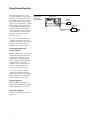
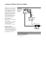
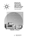
Figure 3-1 illustrates a typical external leveling setup. The power level
feedback to the ALC circuitry is
taken from the external negative
detector, rather than the internal
signal generator detector. The
feedback voltage controls the ALC
system, leveling the RF output
power at the point of detection.
To use detectors and couplers/
splitters for external leveling at
an RF output frequency of 10 GHz
and an amplitude of 0 dBm, follow
the instructions in this section.
Required equipment
• Agilent 8474E negative detector
• Agilent 87301D directional coupler
• cables and adapters, as required
Connect the equipment
Set up the equipment as shown in
Figure 3-1.
4
Figure 3-1.
External detector
leveling with a
directional coupler.
Signal generator
MENUS
E8254A
250 kHz – 40 GHz
PSG -A Series Signal Generator
AM
Frequency
FREQUENCY
GHZ
10.00
RF
ON
Amplitude
dBm
LINE
Local
FM/
ΦM
Utility
Pulse
LF Out
Negative
detector
EXT 2 INPUT
MOD
ON
Hold
Print
O
EXT 1 INPUT
Sweep/
List
AMPLITUDE
40.000 000 000 000
Incr
Set
Save
Recall
7
8
9
4
5
6
Trigger
1
2
3
0
.
+/-
Help
LP OUTPUT
Mod
On/Off
ALC INPUT
RF
On/Off
Return
RF OUTPUT
50Ω
INTERNAL PULSE GENERATOR
I
GATE/PULSE
TRIGGER INPUT
50Ω
VIDEO
OUT
50Ω
SYNC
OUT
50Ω
ALC output
Directional
coupler
REVERSE PWR
! 1W MAX 0V DC
RF output
Leveled
output
Configure the signal generator
1. Press [Preset].
2. Press [Frequency] > [10] > {GHz}.
3. Press [Amplitude] > [0] > {dBm}.
4. Press [RF On/Off].
5. Press {Leveling Mode} > {External Detector}.
This configuration deactivates the internal ALC
detector and switches the ALC input path to the
front panel ALC INPUT connector. The EXT
indicator is activated in the AMPLITUDE area
of the display.
NOTE
For signal generators with Option 1E1, notice that
the ATTN HOLD (attenuator hold) enunciator is
displayed. During external leveling, the signal
generator automatically uncouples the attenuator
from the ALC system for all external leveling points.
While in this mode, RF output amplitude
adjustment is limited to –20 to +25 dBm, the
adjustment range of the ALC circuitry. For more
information, see External Leveling with Option 1E1
Signal Generators on page 6.
6. Observe the coupling factor printed on the
directional coupler at the detector port.
Typically, this value is -10 to -20 dB.
Enter the positive dB value of this coupling factor
into the signal generator.
7. Press {More (1 of 2)} >
{Ext Detector Coupling Factor} > [16] (or the
positive representation of the value listed at the
detector port of the directional coupler) > {dB}.
Leveled output power is now available at
the output of the directional coupler.
NOTE
While operating in external leveling mode, the
signal generator’s displayed RF output amplitude is
affected by the coupling factor value, resulting in a
calculated approximation of the actual
RF output amplitude.
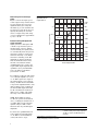
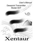
To determine the actual RF output amplitude at the
point of detection, measure the voltage at the
external detector output and refer to Figure 3-2.
5
Figure 3-2 shows the input power
versus output voltage characteristics
for typical diode detectors from
Agilent Technologies. Using this
information, you can determine the
leveled power at the diode detector
input by measuring the external
detector output voltage. The range
of power adjustment is approximately –20 to +25 dB
External leveling with Option 1E1
signal generators
Signal generators with Option 1E1
contain a step attenuator prior to
the RF output connector. During
external leveling, the signal generator automatically holds the present
attenuator setting (to avoid power
transients that may occur during
attenuator switching) as the RF
amplitude is changed. A balance
must be maintained between the
amount of attenuation and the
optimum ALC level to achieve the
required RF output amplitude. For
optimum accuracy and minimum
noise, the ALC level should be
greater than –10 dBm.
Figure 3-2.
Typical diode detector
response at 25° C.
+20 dBV
10V
+10 dBV
+6 dBV
0 dBV
1.0V
Linear
Asymtote
–10 dBV
Detector output voltage
Determining the leveled output
power
100 mV
–20 dBV
Square Law
Asymtote
–30 dBV
10 mV
–40 dBV
–50 dBV
1 mV
–60 dBV
–66 dBV
–70 dBV
0.1 mV
–40
–80 dBV
–30
–20
–10
0
+10
+20
+30
Detector input power, dBm
For example, leveling the CW output
of a 30 dB gain amplifier to a level
of –10 dBm requires the output of
the signal generator to be approximately –40 dBm when leveled. This
is beyond the amplitude limits of the
ALC modulator alone, resulting in
an unleveled RF output. Inserting
45 dB of attenuation results in an
ALC level of +5 dBm, well within
the range of the ALC modulator.
NOTE For modulated carriers,
55 dB is the preferred attenuation
choice, resulting in an ALC level of
+15 dBm. This provides adequate
dynamic range for AM or other
functions that vary the RF output
amplitude.
1. Press [Set Atten] > [45] > {dB}.
2. Press [Set ALC Level] > [5] > {dBm}.
To achieve the optimum ALC level
at the signal generator RF output
of –40 dBm for an unmodulated
carrier, follow these steps:
6
To obtain flatness-corrected power, refer to
Creating and Applying User Flatness Correction.
This sets the attenuator to 45 dB and the ALC level
to +5 dBm, resulting in an RF output amplitude of
–40 dBm, as shown in the AMPLITUDE area of
the display.
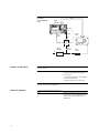
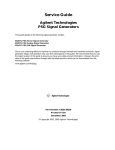
Leveling with a Millimeter-Wave Source Module
Millimeter-wave source module leveling is similar to external detector
leveling. The power level feedback
signal to the ALC circuitry is taken
from the millimeter-wave source
module, rather than the internal
signal generator detector. This feedback signal levels the RF output
power at the mm-wave source
module output through the signal
generator’s rear panel source
module interface connector.
Figure 3-3.
External Millimeterwave source module
leveling for a signal
generator without
Option 1EA.
Signal generator
MENUS
E8254A
250 kHz – 40 GHz
PSG -A Series Signal Generator
FREQUENCY
GHZ
10.00
RF
ON
dBm
Print
LINE
AM
Amplitude
FM/
ΦM
Utility
Pulse
LF Out
Sweep/
List
EXT 2 INPUT
MOD
ON
Hold
O
EXT 1 INPUT
Frequency
AMPLITUDE
40.000 000 000 000
Local
Incr
Set
Save
Recall
7
8
9
4
5
6
1
2
3
Trigger
0
.
+/-
Help
LP OUTPUT
Mod
On/Off
ALC INPUT
RF
On/Off
Return
RF OUTPUT
50Ω
INTERNAL PULSE GENERATOR
I
GATE/PULSE
TRIGGER INPUT
50Ω
VIDEO
OUT
50Ω
SYNC
OUT
50Ω
REVERSE PWR
! 1W MAX 0V DC
Source
module
RF output
Adapter
(If required)
RF input
E8349B
Microwave Amplifier
Required equipment
Microwave
amplifier
RF output
• Agilent 83550 series millimeter-wave
source module
• Agilent 8349B microwave amplifier
(required for signal generators
without Option 1EA)
MM-wave source module
RF input
• cables and adapters, as required
Source module interface
Leveled
output
Connect the equipment
CAUTION To prevent damage to the
signal generator, turn off the line
power to the signal generator before
connecting the source module interface cable to the rear panel source
module interface connector.
1. Turn off the signal generator’s line power.
2. Connect the equipment as shown. Use the
setup in Figure 3-3 for signal generators without
Option 1EA. Use the setup in Figure 3-4 for
Option 1EA signal generators.
7
Figure 3-4.
External Millimeterwave source module
leveling with an
Option 1EA
signal generator.
Signal generator
MENUS
E8254A
250 kHz – 40 GHz
PSG -A Series Signal Generator
AM
Frequency
FREQUENCY
GHZ
10.00
RF
ON
Amplitude
dBm
Print
LINE
Local
FM/
ΦM
Utility
Pulse
LF Out
EXT 2 INPUT
MOD
ON
Hold
O
EXT 1 INPUT
Sweep/
List
AMPLITUDE
40.000 000 000 000
Incr
Set
Save
Recall
7
8
9
4
5
6
1
2
3
Trigger
0
.
+/-
Help
LP OUTPUT
Mod
On/Off
ALC INPUT
RF
On/Off
Return
RF OUTPUT
50Ω
INTERNAL PULSE GENERATOR
I
GATE/PULSE
TRIGGER INPUT
50Ω
VIDEO
OUT
50Ω
SYNC
OUT
50Ω
Source
module
REVERSE PWR
! 1W MAX 0V DC
RF output
Adapter
(If required)
MM-wave source module
Source module interface
Leveled
output
Option 1EA signal generators can drive the output
of millimeter-wave source modules to maximum
specified power without a microwave amplifier.
Configure the signal generator
NOTE
To ensure adequate RF amplitude at the mm-wave
source module RF input when using Option IEA
signal generators, maximum amplitude loss
through the adapters and cables connected
between the signal generator’s RF output and the
mm-wave source module’s RF input which should
be less than 1.5 dB.
1. Turn on the signal generator’s line power.
Upon power-up, the signal generator automatically
senses the mm-wave source module, switches the
signal generator’s leveling mode to external/source
module, sets the mm-wave source module
frequency and amplitude to the source module’s
preset values, and displays the RF output frequency
and amplitude values available at the mm-wave
source module output. The MMMOD indicator in
the FREQUENCY area and the MM indicator in the
AMPLITUDE area of the signal generator’s display
indicate that the mm-wave source module is active.
NOTE
Refer to the mm-wave source module
specifications for the specific frequency
and amplitude ranges.
2. If the RF OFF annunciator is displayed,
press [RF On/Off].
Leveled power is now available at the output of
the millimeter-wave source module.
To obtain flatness-corrected power, refer to
Creating and Applying User Flatness Correction.
8
Creating and Applying User Flatness Correction
Using an Agilent E4416A/17A or
E4418B/19B power meter, you can
create user flatness correction
arrays to correct RF output amplitude variances at user-defined frequencies. After completing a user
flatness correction, the correction
array data can be saved to the signal
generator’s memory catalog and
recalled on demand.
Creating a user flatness
correction array
Follow the steps in the next sections
to create and apply user flatness
correction to the signal generator’s
RF output.
An Agilent E4416A power meter
(controlled by the signal generator
via GPIB) and E4413A power sensor
are used to measure the RF output
amplitude at the specified correction frequencies and transfer the
results to the signal generator. The
signal generator reads the power
level data from the power meter, calculates the correction values, and
stores the correction pairs in the
user flatness correction array.
In this example, you will create a
user flatness correction array. The
flatness correction array contains
ten frequency correction pairs
(amplitude correction values for
specified frequencies), from 1 to
10 GHz in 1-GHz intervals.
If you do not have the required
Agilent power meter or GPIB
interface, you can enter correction
values manually.
Required equipment
• Agilent E4416A power meter
• Agilent E4413A E Series CW power
sensor
• GPIB interface cable
Afterward, follow the steps in
“Recalling and Applying a User
Flatness correction Array” to recall
a user flatness file from the memory
catalog and apply it to the signal
generator’s RF output.
• adapters and cables, as required
NOTE The equipment setup in
Figure 3-5 assumes that if the setup
has an external leveling configuration
you have followed the necessary steps
to correctly level the RF output. If you
have questions about external leveling,
refer to Using External Leveling.
9
Figure 3-5.
User Flatness
Correction Equipment
Setup.
GPIB
Signal
generator
MENUS
E8254A
250 kHz – 40 GHz
PSG -A Series Signal Generator
AM
Frequency
FREQUENCY
GHZ
10.00
RF
ON
Amplitude
dBm
Print
LINE
Local
FM/
ΦM
Utility
Pulse
LF Out
EXT 2 INPUT
MOD
ON
Hold
O
EXT 1 INPUT
Sweep/
List
AMPLITUDE
40.000 000 000 000
Incr
Set
Save
Recall
7
8
9
4
5
6
1
2
0
.
Trigger
Help
LP OUTPUT
ALC input
Mod
On/Off
ALC INPUT
3
+/-
RF
On/Off
Return
RF OUTPUT
50Ω
INTERNAL PULSE GENERATOR
I
GATE/PULSE
TRIGGER INPUT
50Ω
VIDEO
OUT
50Ω
SYNC
OUT
50Ω
REVERSE PWR
! 1W MAX 0V DC
RF output
Source
module
Input
port
Power
meter
Cables
and other
devices
Flatness
corrected
output port
Device
under test
Out
Configure the power meter
In
Power
sensor
1. Zero and calibrate the power
meter and power sensor.
NOTE
If you are using a power meter/sensor combination
other than the Agilent E4416A and E4413A, it may
be necessary to:
a. Enter the appropriate power sensor calibration
factors into the power meter.
b. Enable the power meter’s cal factor array.
For operating information on your particular power
meter/sensor, refer to their operating guides.
Connect the equipment
1. Connect the equipment as shown in Figure 3-5.
NOTE
10
During the user flatness correction process, the
power meter is slaved to the signal generator via
GPIB. No other controllers are allowed on the
GPIB interface.
Configure the signal generator
1. Press [Preset].
2. Press [Amplitude] > {More (1 of 2)} >
{User Flatness} > {Configure Cal Array} >
{More (1 of 2)} > {Preset List} > {Confirm Preset}.
This opens the User Flatness table editor and
presets the correction array
frequency/correction list.
3. Press {Configure Step Array}.
This opens a menu for entering the user flatness
step array data.
4. Press {Freq Start} > [1] > {GHz}.
5. Press {Freq Stop} > [10] > {GHz}.
6. Press {# of Points} > [10] > [Enter].
Steps 4, 5, and 6 enter the desired flatnesscorrected frequencies into the step array.
7. Press [Return] > {Load Cal Array From
Step Array} > {Confirm Load From Step Sweep}.
This populates the user flatness correction
array with the frequency settings defined in the
step array.
8. Press [Amplitude] > [0] > {dBm}.
9. Press [RF On/Off].
This activates the RF output and the RF ON
annunciator is displayed on the signal generator.
NOTE
If using an Agilent E4417A/18A/19A power meter,
follow these steps to configure the signal generator
to perform the user flatness correction:
10. Press [Amplitude] > {More (1 of 2)} >
{User Flatness} > {More (1 of 2)} >
{Power Meter and E4417A, E4418A, or E4419A}.
This allows you to choose another power
meter model.
11. Press [Meter Address] > [enter the power
meter’s GPIB address] > [Enter].
This configures the signal generator to interface
with a power meter at the GPIB address entered.
12. Press [Meter Channel A B] to select the
power meter’s active channel.
13. Press [Meter Timeout] to adjust the length of
time before the instrument generates a timeout
error while unsuccessfully attempting to
communicate with the power meter.
Perform the user flatness correction
NOTE If you are not using an
Agilent E4416A/17A/18A/19A power
meter, or if you do not have GPIB
interface capability, you can perform
the user flatness correction manually.
For instructions, see Performing the
User Flatness Correction Manually.
1. Press {More (1 of 2)} > {User Flatness} >
{Do Cal}.
This performs the user flatness correction. The
signal generator enters the user flatness correction
routine and a progress bar is shown on the display.
2. When prompted, press {Done}.
This loads the amplitude correction values into the
user flatness correction array.
If desired, press {Configure Cal Array}.
This opens the user flatness correction array,
where you can view the stored amplitude
correction values. The user flatness correction
array title displays User Flatness: (UNSTORED)
indicating that the current user flatness correction
array data has not been saved to the
memory catalog.
11
Performing the user flatness
correction manually
If you are not using an Agilent
E4416A/17A/18A/19A power meter
or if you do not have GPIB interface
capability, you can perform the
user flatness correction manually.
Complete the steps in this section
and then continue with the User
Flatness Correction tutorial.
1. Press {More (1 of 2)} > {User Flatness} >
{Configure Cal Array}.
This opens the user flatness table editor and
places the cursor over the frequency value (1 GHz)
for row 1. The RF output changes to the frequency
value of the table row containing the cursor and
1.000 000 000 00 is displayed the AMPLITUDE area
of the display.
2. Observe and record the measured value
from the power meter.
3. Subtract the measured value from 0 dBm.
4. Move the table cursor over the correction
value in row 1.
5. Press {Edit Item} > [enter the difference
value from Step 3] > {dB}.
The signal generator adjusts the RF output
amplitude based on the correction value entered.
6. Repeat Steps 2 through 5 until the power
meter reads 0 dBm.
7. Use the down arrow key to place the cursor over
the frequency value for the next row. The RF output
changes to the frequency value of the table row
containing the cursor, as shown in the AMPLITUDE
area of the display.
8. Repeat Steps 2 through 7 for every entry in
the User Flatness table.
Save the user flatness correction
data to the memory catalog
This process allows you to save the
user flatness correction data as a
file in the signal generator’s memory
catalog. With several user flatness
correction files saved to the memory
catalog, specific files can be
recalled, loaded into the correction
array, and applied to the RF output
to satisfy specific RF output flatness
requirements.
Applying a user flatness
correction arrays
12
1. Press {Load/Store}.
2. Press {Store to File}.
3. Enter the file name FLATCAL1 using the
alphanumeric soft keys and the numeric keypad.
4. Press {Enter}.
The user flatness correction array file FLATCAL1 is
now stored in the memory catalog as a UFLT file.
1. Press [Return] > [Return] > {Flatness Off On}.
This applies the user flatness correction array to
the RF output. The UF indicator is activated in the
AMPLITUDE section of the signal generator’s
display and the frequency correction data
contained in the correction array is applied to the
RF output amplitude.
Recalling and applying a user
flatness correction array
Before performing the steps in this
section, complete Creating a User
Flatness Correction Array.
1. Press [Preset].
2. Press [Amplitude] > {More (1 of 2)} >
{User Flatness} > {Configure Cal Array} >
{More (1 of 2)} > {Preset List} > {Confirm Preset}.
3. Press {More (2 of 2)} > {Load/Store}.
4. Ensure that the file FLATCAL1 is highlighted.
5. Press {Load From Selected File} >
{Confirm Load From File}.
This populates the user flatness correction array
with the data contained in the file FLATCAL1. The
user flatness correction array title displays User
Flatness: FLATCAL1.
6. Press [Return] > {Flatness Off On}.
This applies the user flatness correction data
contained in FLATCAL1.
Returning the signal generator to
GPIB listener mode
1. Save your instrument state to the
instrument state register.
For instructions, see Saving an Instrument State
in example 6 on page 20.
During the user flatness correction
process, the power meter is slaved
to the signal generator via GPIB,
and no other connections are
allowed on the GPIB interface. The
signal generator operates in GPIB
talker mode, as a device controller
for the power meter. In this operating mode, it cannot receive SCPI
commands via GPIB.
2. Press [GPIB Listener Mode].
This presets the signal generator and returns it to
GPIB listener mode. The signal generator can now
receive remote commands executed by a remote
controller connected to the GPIB interface.
3. Recall your instrument state from the
instrument state register.
For instructions, see “Recalling an Instrument
State” in example 6 on page 20.
CAUTION If the signal generator is
interfaced to a remote controller
after performing the user flatness
correction, its GPIB controller mode
must be changed from GPIB talker
to GPIB listener. This is accomplished by presetting the signal
generator. If an RF carrier has
been previously configured, you
must save the present instrument
state before returning the signal
generator to GPIB listener mode.
13
Array Using a MM-Wave Source Module
In this example, a user flatness
correction array is created to provide
flatness-corrected power at the output of an Agilent 83554A millimeterwave source module driven by an
Agilent E8247C signal generator.
The flatness correction array contains
28 frequency correction pairs
(amplitude correction values for
specified frequencies), from 26.5 to
40 GHz in 500 MHz intervals. This
will result in 28 evenly spaced flatness corrected frequencies between
26.5 GHz and 40 GHz at the output
of the Agilent 83554A millimeterwave source module.
Configure the power meter
An Agilent E4416A power meter
(controlled by the signal generator
via GPIB) and R8486A power sensor
are used to measure the RF output
amplitude of the millimeter-wave
source module at the specified correction frequencies and transfer the
results to the signal generator. The
signal generator reads the power
level data from the power meter,
calculates the correction values,
and stores the correction pairs in
the user flatness correction array.
If you do not have the required
Agilent power meter or GPIB interface, you can enter correction values
manually.
Required equipment
• Agilent 83554A mm-wave source
module
• Agilent E4416A power meter
• Agilent R8486A power sensor
• Agilent 8349B microwave amplifier
(required for signal generators
without option 1EA)
• GPIB interface cable
• adapters and cables as required
NOTE The equipment setups in
Figure 3-6 and Figure 3-7 assume
that, if the setups have an external
leveling configuration, the steps necessary to correctly level the RF output have been followed. If you have
questions about external leveling,
refer to “Leveling with a MillimeterWave Source Module” in example 6
on page 19
1. Zero and calibrate the power meter
and power sensor.
2. Enter the appropriate power sensor
calibration factors into the power meter.
3. Enable the power meter’s cal factor array.
NOTE
Connect the equipment
1. Turn off the line power to the signal generator.
CAUTION To prevent damage to the
signal generator, turn off the line
power to the signal generator before
connecting the source module interface cable to the rear panel source
module interface connector.
2. Connect the equipment. For standard signal
generators, use the setup in Figure 3-6. For
Option 1EA signal generators, use the setup
in Figure 3-7.
14
For operating information on your particular power
meter/sensor, refer to their operating guides.
NOTE
During the user flatness correction process, the
power meter is slaved to the signal generator via
GPIB. No other connections are allowed on the
GPIB interface.
NOTE
When using Option 1EA signal generators, to
ensure adequate RF amplitude at the mm-wave
source module RF input, maximum amplitude loss
through the adapters and cables connected
between the signal generator’s RF output and the
mm-wave source module’s RF input should be
less than 1.5 dB.
Figure 3-6.
User flatness with
mm-wave source
module for a signal
generator without
Option 1EA.
GPIB
Signal generator
MENUS
E8254A
250 kHz – 40 GHz
PSG -A Series Signal Generator
FREQUENCY
GHZ
10.00
RF
ON
dBm
AM
Sweep/
List
Amplitude
FM/
ΦM
Utility
Pulse
LF Out
EXT 2 INPUT
MOD
ON
Hold
Print
O
LINE
Power
meter
EXT 1 INPUT
Frequency
AMPLITUDE
40.000 000 000 000
Local
Incr
Set
Save
Recall
7
8
9
4
5
6
Trigger
1
2
3
0
.
Help
LP OUTPUT
Mod
On/Off
ALC INPUT
+/-
RF
On/Off
Return
RF OUTPUT
50Ω
INTERNAL PULSE GENERATOR
I
GATE/PULSE
TRIGGER INPUT
50Ω
VIDEO
OUT
50Ω
SYNC
OUT
50Ω
REVERSE PWR
! 1W MAX 0V DC
RF output
Source
module
RF input
E8349B
Microwave
amplifier
Microwave Amplifier
Power
sensor
RF output
MM-wave source module
RF Input
Source module interface
Leveled
output
Figure 3-7.
User flatness with
mm-wave source
module and option 1EA
signal generator.
GPIB
Signal generator
MENUS
E8254A
250 kHz – 40 GHz
PSG -A Series Signal Generator
FREQUENCY
GHZ
10.00
RF
ON
dBm
LINE
AM
Sweep/
List
Amplitude
FM/
ΦM
Utility
Pulse
LF Out
EXT 2 INPUT
MOD
ON
Hold
Print
O
Power
meter
EXT 1 INPUT
Frequency
AMPLITUDE
40.000 000 000 000
Local
Incr
Set
Save
Recall
7
8
9
4
5
6
Trigger
1
2
3
0
.
+/-
Help
LP OUTPUT
Mod
On/Off
ALC INPUT
RF
On/Off
Return
RF OUTPUT
50Ω
INTERNAL PULSE GENERATOR
I
GATE/PULSE
TRIGGER INPUT
50Ω
VIDEO
OUT
50Ω
SYNC
OUT
50Ω
REVERSE PWR
! 1W MAX 0V DC
RF output
Source
module
Power
sensor
MM-wave source module
RF input
Source module interface
Leveled
output
15
Configure the signal generator
1. Turn on the signal generator’s line power.
Upon power-up, the signal generator automatically:
senses the mm-wave source module, switches the
signal generator’s leveling mode to external/source
module, sets the mm-wave source module
frequency and amplitude to the source module’s
preset values, and displays the RF output frequency
and amplitude values available at the mm-wave
source module output. The MMMOD indicator in
the FREQUENCY area and the MM indicator in the
AMPLITUDE area of the signal generator’s display
indicate that the mm-wave source module is active.
NOTE
Refer to the mm-wave source module
specifications for the specific frequency and
amplitude ranges.
2. Press [Amplitude] > {More (1 of 2)} >
{User Flatness} > {Configure Cal Array} >
{More (1 of 2)} > {Preset List} > {Confirm Preset}.
This opens the User Flatness table editor and
resets the correction array frequency/
correction list.
3. Press {Configure Step Array}.
This opens a menu for entering the user flatness
step array data.
4. Press {Freq Start} > [26.5] > {GHz}.
5. Press {Freq Stop} > [40] > {GHz}.
6. Press {# of Points} > [28] > {Enter}.
This enters the desired flatness-corrected
frequencies (26.5 GHz to 40 GHz in 500 MHz
intervals) into the step array.
7. Press [Return] > {Load Cal Array From
Step Array} > {Confirm Load From Step Sweep}.
This populates the user flatness correction array
with the frequency settings defined in the
step array.
8. Press [Amplitude] > [0] > {dBm}.
16
9. Press [RF On/Off].
This activates the RF output and the RF ON
enunciator is displayed on the signal generator.
NOTE
If using a power meter other than an E4416A,
follow these steps to configure the signal generator
to perform the user flatness correction.
10. Press [Amplitude] > {More (1 of 2)} >
{User Flatness} > {More (1 of 2)} > {Power Meter
and E4417A, E4418A, or E4419A}.
This allows you to choose another
power meter model.
11. Press {Meter Address} > [enter the power
meter’s GPIB address] > {Enter}.
This configures the signal generator to interface
with a power meter at the GPIB address entered.
12. Press {Meter Channel A B} to select the power
meter’s active channel.
For E4419B and E4417B
13. Press [Meter Timeout] to adjust the length of
time before the instrument generates a timeout error
while unsuccessfully attempting to communicate
with the power meter.
For E4419B and E4417B
Perform the user flatness correction
NOTE If you are not using an
Agilent E4416A/17A/18A/19A power
meter, or if you do not have GPIB
interface capability, you can perform
the User Flatness Correction
manually. For instructions, see
“Performing the User Flatness
Correction Manually.”
1. Press {More (1 of 2)} > {User Flatness} >
{Do Cal}.
This performs the user flatness correction. The
signal generator enters the user flatness correction
routine and a progress bar is shown on the display.
2. When prompted, press {Done}.
This loads the amplitude correction values into the
user flatness correction array.
If desired, press {Configure Cal Array}.
This opens the user flatness correction array,
where you can view the list of defined frequencies
and their calculated amplitude correction values.
The user flatness correction array title displays
User Flatness: (UNSTORED) indicating that the
current user flatness correction array data has not
been saved to the memory catalog.
17
User Flatness Correction Manually
If you are not using an Agilent
E4416A/17A/18A/19A power meter
or if you do not have GPIB interface
capability, you can perform the User
Flatness Correction manually.
Complete the steps in this section
and then continue with the User
Flatness Correction tutorial.
1. Press [More (1 of 2)] > {User Flatness} >
{Configure Cal Array}.
This opens the User Flatness table editor and
places the cursor over the frequency value
(26.5 GHz) for row 1. The RF output changes to the
frequency value of the table row containing the
cursor and 26.500 000 000 00 is displayed the
AMPLITUDE area of the display.
2. Observe and record the measured value
from the power meter.
3. Subtract the measured value from 0 dBm.
4. Move the table cursor over the
correction value in row 1.
5. Press {Edit Item} > [enter the difference value
from Step 3] > {dB}.
The signal generator adjusts the RF output
amplitude based on the correction value entered.
6. Repeat Steps 2 through 5 until the power
meter reads 0 dBm.
7. Use the down arrow key to place the cursor
over the frequency value for the next row.
8. Repeat Steps 2 through 7 for every entry in
the User Flatness table.
18
The RF output changes to the frequency value
of the table row containing the cursor, as shown in
the AMPLITUDE area of the display.
Save the User Flatness Correction Data to the
Memory Catalog
This process allows you to save the
user flatness correction data as a
file in the signal generator’s memory
catalog. With several user flatness
correction files saved to the memory
catalog, specific files can be
recalled, loaded into the correction
array, and applied to the RF output
to satisfy various RF output flatness
requirements.
1. Press {Load/Store}.
4. Press {Enter}.
The user flatness correction array file FLATCAL2 is
now stored in the memory catalog as a UFLT file.
Applying the user flatness
correction array
1. Press [Return] > [Return] > {Flatness Off On}.
This applies the user flatness correction array to
the RF output. The UF indicator is activated in the
AMPLITUDE section of the signal generator’s
display and the frequency correction data
contained in the correction array is applied to the
RF output amplitude of the mm-wave
source module.
Recalling and applying a user
flatness correction array
1. Press [Preset].
Before performing the steps in this
section, complete the section
Creating a User Flatness Correction
Array Using a MM-Wave Source
Module.
2. Press {Store to File}.
3. Enter the file name FLATCAL2 using the
alphanumeric soft keys and the numeric keypad.
2. Press [Amplitude] > {More (1 of 2)} >
{User Flatness} > {Configure Cal Array} >
{More (1 of 2)} > {Preset List} > {Confirm Preset}.
3. Press [More (2 of 2)] > {Load/Store}.
4. Ensure that the file FLATCAL2 is highlighted.
5. Press {Load From Selected File} >
{Confirm Load From File}.
This populates the user flatness correction array
with the data contained in the file FLATCAL2. The
user flatness correction array title displays User
Flatness: FLATCAL2.
6. Press [Return] > {Flatness Off On}.
This activates flatness correction using the data
contained in the file FLATCAL2.
19
To find out more visit:
www.agilent.com/find/psg
Related Agilent literature
Agilent PSG Signal Generators, Brochure,
Literature number 5988-7538EN
Agilent E8267C PSG Vector Signal Generator, Data Sheet,
Literature number 5988-6632EN
Agilent E8247C/E8257C PSG Analog/CW Signal Generator, Data Sheet,
Literature number 5988-7454EN
Agilent PSG Vector Signal Generator Self Guided Demo,
Literature number 5988-8087EN
Agilent E8247C/E8257C PSG Analog/CW Self Guided Demo,
Literature number 5988-2414EN
Agilent E8267C PSG Vector Configuration Guide,
Literature number 5988-7541EN
Agilent E8247C/E8257C PSG Analog/CW Configuration Guide,
Literature number 5988-7879EN
Agilent PSG Series Product Note: Millimeter Head,
Literature number 5988-2567EN
Agilent PSG Two-tone and Multi-tone, Application Note 1410,
Literature number: 5988-7689EN
www.agilent.com/find/emailupdates
Get the latest information on the products and applications you select.
Agilent Technologies’ Test and Measurement Support,
Services, and Assistance
Agilent Technologies aims to maximize the value you
receive, while minimizing your risk and problems. We
strive to ensure that you get the test and measurement
capabilities you paid for and obtain the support you need.
Our extensive support resources and services can help
you choose the right Agilent products for your applications
and apply them successfully. Every instrument and system
we sell has a global warranty. Support is available for at
least five years beyond the production life of the product.
Two concepts underlie Agilent’s overall support policy:
“Our Promise” and “Your Advantage.”
Our Promise
Our Promise means your Agilent test and measurement
equipment will meet its advertised performance and
functionality. When you are choosing new equipment, we
will help you with product information, including realistic
performance specifications and practical recommendations
from experienced test engineers. When you use Agilent
equipment, we can verify that it works properly, help with
product operation, and provide basic measurement assistance for the use of specified capabilities, at no extra cost
upon request. Many self-help tools are available.
Your Advantage
Your Advantage means that Agilent offers a wide range of
additional expert test and measurement services, which
you can purchase according to your unique technical and
business needs. Solve problems efficiently and gain a
competitive edge by contracting with us for calibration,
extra-cost upgrades, out-of-warranty repairs, and onsite
education and training, as well as design, system integration, project management, and other professional engineering services. Experienced Agilent engineers and
technicians worldwide can help you maximize your productivity, optimize the return on investment of your Agilent
instruments and systems, and obtain dependable measurement accuracy for the life of those products.
Agilent T&M Software and Connectivity
Agilent’s Test and Measurement software and connectivity
products, solutions and developer network allows you to
take time out of connecting your instruments to your computer with tools based on PC standards, so you can focus
on your tasks, not on your connections. Visit
www.agilent.com/find/connectivity
for more information.
By internet, phone, or fax, get assistance with all your
test & measurement needs
Phone or Fax
United States:
(tel) 800 452 4844
Canada:
(tel) 877 894 4414
(fax) 905 282 6495
China:
(tel) 800 810 0189
(fax) 800 820 2816
Europe:
(tel) (31 20) 547 2323
(fax) (31 20) 547 2390
Japan:
(tel) (81) 426 56 7832
(fax) (81) 426 56 7840
Korea:
(tel) (82 2) 2004 5004
(fax) (82 2) 2004 5115
Latin America:
(tel) (305) 269 7500
(fax) (305) 269 7599
Taiwan:
(tel) 0800 047 866
(fax) 0800 286 331
Other Asia Pacific
Countries:
(tel) (65) 6375 8100
(fax) (65) 6836 0252
Email:
[email protected]
Online Assistance:
www.agilent.com/find/assist
Product specifications and descriptions in this document
subject to change without notice.
© Agilent Technologies, Inc. 2001, 2003
Printed in USA, February 4, 2003
5988-2410EN