1
US00827 l 713B2
(12) Umted States Patent
(10) Patent N0.2
Grady et al.
(45) Date of Patent:
(54) INTERFACE SYSTEMS FOR PORTABLE
(75)
US 8,271,713 B2
Sep. 18, 2012
‘(Z/11210813: a1~ l
,
,
0yt1c
eta .
DIGITAL MEDIA STORAGE AND PLAYBACK
DEVICES
6,782,239 B2
6,836,643 B2
6,973,477 B1
8/2004 Johnson et a1‘
12/2004 Shealtiel
12/2005 Martino
Inventors: Jeff Grady, Charleston, SC (US); Garey
.
De Angehs’ Charleston’ SC ms)’
6,978,475 B1
7,065,778 B1
7,076,202 B1
12/2005 Kunin et al.
6/2006 Lu
7/2006 Billmaier
Andrew Green’ Mount Pleasant’ SC
7 529 871 B1
5/2009 Schubert et al.
(US); Vincent K. Gustafson, Chapel
2002/0002039 A1
1/2002 Qureshey et a1.
H111, NC (Us)
(Continued)
(73) Assignee: Philips Electronics North America
COrPOratiOmAndOVer, MA (Us)
( * ) Notice:
FOREIGN PATENT DOCUMENTS
JP
2002007004 A
Subject to any disclaimer, the term of this
patent is extended or adjusted under 35
1/2002
(Continued)
U.S.C. 154(b) by 1453 days.
OTHER PUBLICATIONS
AVR 140 Audio/ Video Receiver Owner’ s Manual, Found online Mar.
(21) Appl. No.: 11/549,614
28,
2007
at
http://manualsharmancom/HIQ
OWner%27s%20Manual/AVR%20 l40%20OM%20(Web)%203
(22)
29-06.pdf, 2006, Publisher: Harman International Industries, inc.
Filed:
Oct. 13, 2006
(65)
Prior Publication Data
US 2008/0089667 A1
(Continued)
Apr. 17, 2008
Primary Examiner * Thai Tran
Assistant Examiner * MishaWn Dunn
(51)
(52)
Int. Cl.
G06F 13/00
(2006.01)
US. Cl. ...... .. 710/303; 386/219, 386/231;.386/234;
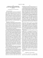
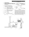
A docking assembly Serves as an interface between (1) a
(58)
_
_
_
455/39’ 455/412’ 715/864
Fleld of Classl?catlon Search .................. .. 386/46,
portable digital media storage and playback (PDMSP)
device’ and (2) a media reproduction system_ A remote Con_
386/83’ 95’ 96’ 200> 213> 216> 219> 23 1’
386/234; 715/864; 710/303; 455/39’ 412;
troller preferably controls the docking assembly and PDMSP
device, Which may receive electric charge from the assembly.
_
_
713/189’ 193
See apphcanon ?le for Complete Search hlstory_
(56)
1/2001 Fogle
5/2001 Jadoul
4/2002 Perkes
6,423,892 B1
7/2002 Ramaswamy
6,545,722 B1
4/2003 Schultheiss et al.
signals in user-perceptible form. Telephonic relay capability
assembly. Methods for downloading digital media ?les, and
8/1998 Antos
6,175,926 B1
Media reproduction systems may reproduce audio and video
phone rebroadcast receiver associated With the docking
U.S. PATENT DOCUMENTS
6,240,297 B1
6,373,503 B1
ABSTRACT
is further provided betWeen a telephonic PDMSP playback
device and a telephonic remote controller by Way of a tele
References Clted
5,790,201 A
(57)
for creating or modifying playlists With a remotely control
lable docking assembly adapted to provide a television-com
patible video output signal, are further provided.
23 Claims, 11 Drawing Sheets
%
Mlclouocsaol
YELEVIsInnnOMPAYIBLE
mlruv ELEMlM
US 8,271,713 B2
Page 2
US. PATENT DOCUMENTS
2002/0032042
2002/0072390
2002/0077834
2002/0098813
2002/0105861
2002/0132651
2002/0151327
2003/0041206
A1
A1
A1
A1
A1
A1
A1
A1
3/2002
6/2002
6/2002
7/2002
8/2002
9/2002
10/2002
2/2003
2003/0154355 A1*
2004/0107253
2004/0171346
2004/0193900
2004/0224638
2005/0062695
2005/0088620
2005/0135790
2005/0195848
2005/0227773
2006/0026326
2006/0031617
2006/0039263
2006/0156415
2006/0184978
2006/0274910
2007/0055396
2007/0077784
2007/0086724
8/2003
Poplawsky et a1.
Uchiyama
EsteveZ
LikoureZos et al.
Leapman
Jinnouchi
Levitt
Dickie
Fernandez .................. .. 711/163
A1
6/2004 Ludwig et al.
A1
9/2004 Lin
A1
9/2004 Nair
A1
11/2004 Fadelletal.
A1
3/2005 Coketal.
A1
4/2005 DWyeretal.
A1
6/2005 Hutten ........................ .. 386/125
A1
9/2005 Braneciet al.
. 370/421
A1
10/2005 Luetal. .... ..
472/60
A1
2/2006 Hunt etal. .................. .. 710/303
A1
2/2006 Falcon
A1
2/2006 Trotabas
A1
7/2006 Rubinstein et al.
A1
8/2006 Casey
A1
12/2006 Schulet a1.
A1* 3/2007 Hedges et al. ................ .. 700/94
A1
4/2007 Kalayjian et al.
A1
4/2007 Grady et al.
#94
Harman Kardon G0 + Play Portable Loudspeaker for iPod, Found
online Mar. 28, 2007 at http://WWW.mobileWhack.com/revieWs/har
manikardonggoiplayiportableiloudspeakeriforiipod.htrnl,
2006, Publisher: MobileWhack.com.
SanDisk, SanDisk Photo Album, found online Mar. 27, 2007 at
http://WWW.sandisk.com/Products/Item(1153)-SDV2-A
SanDiskPhotoiAlbumaspx, 2006, Publisher: SanDisk Corporation.
SanDisk, SanDisk Photo Album User Guide, found online Mar. 27,
2007 at http://WWW.sandisk.com/Assets/File/tech/docs/spa-user
guide-v1.1.pdf, 2004, Publisher: SanDisk Corporation.
Shop 4 Tech, Digital Photo Viewer Photo Album by SanDisk, found
online Sep. 20, 2006 at WWW.shop4tech.com, 2006, Publisher:
Shop4tech.com.
Spero, Ricky, RGVIGWiHBIIIlZlII/KBICIOIYS Drive+Play, The Mac
Observerifound online Mar. 27, 2007 at http://WWW.macobserver.
com/revieW/2006/01/09.1.shtrnl, Apr. 14, 2006.
Vega, Michael, Complete battery-pack design for one- or two-cell
portable applications, Analog Applications Journalifound online
Mar. 28, 2007 at http://focus.ti.com/lit/an/slyt248/slyt248.pdf, 2006,
pp. 14-16, vol. 3Q, Publisher: Texas Instruments, Inc.
Grif?n 9801-TCENTER WiFi TuneCenter Home Media Center for
iPod, Found online Mar. 28, 2007 at http://WWW.amaZon.com/Grif
?n-9801-TCENTER-TuneCenter-Media-Center, 2006, Publisher:
AmaZon.com.
Apple iPod Universal Dock, The Apple Storeifound online Mar. 28,
2007 at http://store.apple.com/1-800-MY-APPLE/WebObjects/Ap
pleStore.Woa/Wa/RSLID?mco:6C04E07A
2007/0101039 A1*
5/2007 Rutledge et al. ............ .. 710/303
&nplm:MA045G%2FC, 2007, Publisher: Apple Computer.
2007/0124804 A1
5/2007 Burnham et a1.
iPod: TV Out Support, Found online Mar. 28, 2007 at http://docs.
2007/0250571 A1
10/2007 Grif?n, Jr.
info.apple.com/article.html?artnum:300233,
2007/0300155 A1*
12/2007
Apple Computer.
2008/0015717
2008/0025172
2008/0089658
2008/0092200
2008/0138028
A1
A1
A1
A1
A1
1/2008
1/2008
4/2008
4/2008
6/2008
Laeferet a1. ................ .. 715/700
Grif?n, Jr. et al.
Holden et a1.
Grady et al.
Grady et al.
Grady et al.
2006,
Publisher:
Hiner, Kirk, Harman Kardon ‘bridges’ iPod and home entertainment
systems, Applelinks.comifound online Mar. 27, 2007 at http://
WWW. applelinks .com/ index .php/more/harmanikardoni
quotbridgesguotiipodiandihomeientertainmentisy Nov.
4,
2005, Publisher: CFC Productions.
FOREIGN PATENT DOCUMENTS
JP
KR
TW
TW
TW
TW
TW
TW
TW
TW
WO
2002-007004
10-2001-0037642
M247950
M249138
M253152
M268823
M290351
M292861
M294783
M298843
WO-2006/073702
A1
A
B
B
B
B
B
B
B
B
A1
1/2002
5/2001
10/2004
11/2004
12/2004
6/2005
5/2006
6/2006
7/2006
10/2006
7/2006
OTHER PUBLICATIONS
Installing Harman Kardon’s Drive + Play, Found online Mar. 28,
2007 at http://WWW.harmankardon.com/drive-1/docs/install.pdf,
2007, Publisher: Harman Kardon.
Entertainment Dock 500 for iPod, found online Mar. 27, 2007 at
http://us.kensington.com/html/10117.html,
2006,
Publisher:
Kensington Computer Products Group.
Di Jasio, Lucio, Using KEELOQ to Validate Subsystem Compatibil
ityiAN827, Application Notesifound online Mar. 28, 2007 at
http://WW1 .microchip.com/doWnloads/en/AppNotes/ 00 827a.pdf,
2002, Publisher: Microchip Technology Inc.
Application Note 1904Challenge and Response With l-Wire SHA
devices, Found online Mar. 28, 2007 at http://WWW.maxim-ic.com/
appnotes.cfm/appnoteinumber/ 190, Mar. 12, 2002, Publisher:
Maxim Integrated Products.
DS2703iSHA-1 Battery Pack Authentication IC, Found online
Mar. 28, 2007 at http://datasheets.maxim-ic.com/en/ds/DS2703.pdf,
2007, Publisher: Maxim Integrated Products.
TuneCenteriHome Media Center for iPod, found online at http://
WWW.grif?ntechnology.com/products/tunecenter/, 2006, Publisher:
Grif?n Technology.
Harman/Kardon, The Bridge4OWner’s Manual, Found on-line Feb.
21, 2007 at httpSZ//WWW.hCl-S€IV1C€S.COIIl/KGChfClOC/CIOCUJHGIIIS,
2005, Published in: Northridge, CA.
Apple Expo: Harman Kardon Introduces Car Audio Solution for the
iPod, found online Mar. 27, 2007 at httpZ//WWW.PII1€WSW1I€.CO.U1</
cgi/neWs/release?id:154010, Sep.
19, 2005, Publisher: PR
NeWsWire on behalf of Harman Consumer Group International.
iPod AV Connection Kit, The Apple Storeifound online Mar. 28,
2007 at http://store.apple.com/1-800-MY-APPLE/WebObjects/Ap
pleStore.Woa/Wa/RSLID?mco:6C04E07A
&nplm:MA242LL%2FC, 2007, Publisher: Apple Computer.
Co-pending U.S. Appl. No. 11/400,414.
US. Appl. No. 11/400,414, Grif?n, Paul, Jr.
* cited by examiner
US. Patent
Sep. 18, 2012
US 8,271,713 B2
Sheet 1 0f 11
PEG
41
WIRELESS
REMOTE
»r
CONTROL
L51
[L
LN” 32
f/ \ 81
___
\
PORTABLE
\I-l
\\
\
M
I
19
\
18
1
14\
x
l
DIGITAL
‘I
I
MEDIA
l
I
STORAGE
l
I
AND
‘--
PLAYBACK
\I/
DEV'CE
12
15
1?
/
f
f
16
f
/
WIRE-
WIRELESS
NELT?gRK
J53;
TRANS-
TRANS-
CEIVER
CEIVER
A
HEAD-
WIRELESS
REMOTE
ELECTRICALCOUPLING(S)
‘aim-E
RECEIVER
INPUT
A
I
‘P
USER
LgfspfL
CONTROLS
PLAY
Q
AUTHEN
_
TIcATIoN
_
ELEMENT
‘3
’
m
MEM,
’
43 Q
VIDEO
ORY
13 Q
I--
f
LEDS I
LOCAL
CEEQSR ‘
7
x
g
I‘
‘J44
21”” 5
%
MICROPROCESSOR
4t?
DSP
‘“
48
AMP
{-
4Q
26*"
21
REMOTE
a POWER
PORT
W'RELESS
RElfgg’TER
,
R"|‘EI:IT(§$E
PORT
Ft‘éRaT
PORT
i
I
l
MEDIA
POWER
WIRELESS
SYSTEM
*-
SUPPLY
RECEIVER
DEVICE
_
38
3?}
/
\
4:?» cAMERA
1C:
DEVICE
_
_
_
_
_
_
_
_
DATA!
w,
WORK
AC
VIDEO
P°RT($)
as 32
MEDIANET-
35» POWER
AIV
PORTISI
1
26¢30
REMOTE
[P
AUDIO
PORTIS)
PORT
‘P22 Q 23%24
35
9'
4Q
I
4O
AMPLIFIER
t
2
4,
souRcE
To
I
I
I
I
I
|
I
I
I
I
I
I
WIRELESS
REMOTE
CONTROL
-
6
i
E
1
99
o
SPEAKER(S)
5“
TELEVISION-COMPATIBLE
DISPLAY ELEMENT
I
I
I
l
I
I
US. Patent
Sep. 18, 2012
‘I86
186
000’
-182
185A~
-
-
-
18%
US 8,271,713 B2
Sheet 2 0f 11
US. Patent
Sep. 18, 2012
US 8,271,713 B2
Sheet 4 0f 11
‘150
WU
0FZ
W
w
M
w
F
E
4|Al‘. 5 7.7,7 C
A4!4l|- 5 27;7.w:7 G
D
i
H
M
m
u
9W6W3m
P
7m
3
it 157x
"168
162
150
f
16§A
US. Patent
Sep. 18, 2012
211%:
"
Sheet 5 0111
w'
US 8,271,713 B2
US. Patent
Sep. 18, 2012
21m
/
[i
2118
Sheet 6 0111
US 8,271,713 B2
216A
\
@2111
US. Patent
Sep. 18, 2012
180
I
Sheet 7 0111
US 8,271,713 B2
157A
I
“166
157%
j
156
US. Patent
Sep. 18, 2012
Sheet 8 0111
US 8,271,713 B2
386
PORTABLE DIGITAL MEDIA
395
/
STORAGE AND PLAYBACK DEVICE
i
j
|
I
|
SEIEERYET —> PLAIEyE-JEXT
|
CHALLENGE
I
|
|
|
|
|
|
I
|
|
|
|
HOST-
|
| CHALLENGER
FAIL
A
1317;;
|
| RESPON DER
|
|
|
I
:
|
|
|
|
ENCRYPTED
KEY
PLAIN-TEXT
KEY
l
CALCL LATED
ANSYVER
l
I
A
AUTHENTICATION
TRANSFORM
|
|
|
|
‘
‘
REMOTE CONTROLLED
DOCKING ASSEMBLY
313
31G
US. Patent
Sep. 18, 2012
Sheet 9 0111
@\
\___\\\
1}!
\\\\
\\\\\\\
US 8,271,713 B2
US. Patent
Sep. 18, 2012
Sheet 10 0111
US 8,271,713 B2
400
COMMUNICATIVELY COUPLE, VIAA REMOTELY
CONTROLLABLE DOCKING ASSEMBLY, A PORTABLE
m
DIGITAL MEDIA STORAGE AND PLAYBACK DEVICE
HAVING A FIRST DISPLAY ELEMENT WITH AN AUDIO AND
VIDEO REPRODUCTION SYSTEM HAVING ATELEVISION
COMPATIBLE SECOND DISPLAY ELEMENT
404 --
I
I
CONNECT TO MEDIA SOURCE
IDENTIFY ON THE SECOND DISPLAY ELEMENT
______
INFORMATION INDICATIVE OF AT LEAST ONE DIGITAL
MEDIA FILE AND/OR DIGITAL MEDIA FILE KEY
OBTAINABLE FROM THE MEDIA SOURCE
I
SELECT, USING A REMOTE CONTROLLER, A DIGITAL
_____
MEDIA FILE AND/OR DIGITAL MEDIA FILE KEY FOR
DOWNLOAD OR TRANSFER TO THE PORTABLE DIGITAL
MEDIA STORAGE AND PLAYBACK DEVICE
I
COMMIT, USING THE REMOTE CONTROLLER, TO
416 m FINANCIAL OBLIGATION IN EXCHANGE FOR DOWNLOAD
OR TRANSFER OF DIGITAL MEDIA FILE KEY AND/OR
DIGITAL MEDIA FILE KEY
US. Patent
Sep. 18, 2012
Sheet 11 0111
US 8,271,713 B2
459
COMMUNICATIVELY COUPLE, VIAA REMOTELY
CONTROLLABLE DOCKING ASSEMBLY, A PORTABLE
DIGITAL MEDIA STORAGE AND PLAYBACK DEVICE
M HAVING A FIRST DISPLAY ELEMENT WITH AN AUDIO AND
VIDEO REPRODUCTION SYSTEM HAVING ATELEVISION
COMPATIBLE SECOND DISPLAY ELEMENT
I
CREATE OR RETRIEVE A PLAYLIST USING A REMOTE
M
CONTROLLER, WITH INFORMATION INDICATIVE OF THE
CREATED OR RETRIEVED PLAYLIST DISPLAYED ON THE
SECOND DISPLAY ELEMENT
I
DISPLAY INFORMATION INDICATIVE OF AT LEAST ONE
4 6
5
DIGITAL MEDIA FILE STORED ON THE PORTABLE DIGITAL
m
MEDIA STORAGE AND PLAYBACK DEVICE ON THE
SECOND DISPLAY ELEMENT
I
SELECT FOR ADDITION TO OR DELETION FROM THE
""'"""
CREATED OR RETRIEVED PLAYLIST THE AT LEAST ONE
DIGITAL MEDIA FILE USING A REMOTE CONTROLLER
I
SELECT FOR STORAGE ON THE PORTABLE DIGITAL
MEDIA STORAGE AND PLAYBACK DEVICE AND/OR A
46% "m
MEMORY ASSOCIATED WITH THE REMOTELY
CONTROLLABLE DOCKING ASSEMBLY TI-IE MODIFIED
PLAYLIST
US 8,271,713 B2
1
2
INTERFACE SYSTEMS FOR PORTABLE
DIGITAL MEDIA STORAGE AND PLAYBACK
DEVICES
the PDMSP device to a group of persons, such as in a room or
in the passenger compartment of a passenger vehicle.
Another limitation associated With conventional PDMSP
devices is their reliance on personal computers as a primary
interface for loading, purchasing, and organiZing media ?les.
BACKGROUND OF THE INVENTION
Aside from the expense attendant to personal computers, such
devices are often tailored for and stationed in rooms desig
nated for Workisuch as o?icesiand may be dif?cult to
1. Field of the Invention
This invention relates to accessories for portable digital
media storage and playback devices used for on-line doWn
integrate With multimedia (e.g., television, audio, and com
munication) entertainment devices tailored for and stationed
loading, storing and playing digital media ?les such as, for
example, MP3 (i.e., MPEG-l audio layer 3) audio, WMA
(Windows Media Audio) audio, MPEG-4 multimedia, and
home theaters. An oWner of a personal computer may desire
in rooms designated for recreationisuch as living rooms or
to unWind by purchasing or organiZing multimedia ?les for
storage and vieWing on a PDMSP device, yet avoid the pro
QuickTime multimedia ?les. More speci?cally, the invention
cess altogether so as to avoid the temptation to check email
relates in various aspects to a multi-function docking assem
messages as they arrive to the computer. Additionally, fur
bly, preferably remotely controllable, providing any of the
nishings in entertainment rooms such as living rooms and
folloWing functions: signal transmission, signal relaying,
remote control, remote video interface, poWer supply and/or
charging, and authentication for portable digital media stor
age and playback devices, and methods pertaining to the
home theaters usually are substantially more inviting and
comfortable than o?ice chairs. Thus, a highly functional
accessory device for interfacing With PDMSP devices, With
20
such accessory being suitable for use in entertainment rooms
and not requiring use of a personal computer, Would be desir
able.
Yet another limitation associated With conventional
25
leading to the occasional di?iculty of alerting the user to
same.
2. Description of the Related Art
Media players of various types are ubiquitous throughout
the World, and have evolved through various forms over the
years, from portable single transistor radios in the 1950’s to
tape cassette players, to compact disc players, and more
PDMSP devices is their absorptive entertainment quality,
potentially important interruptions such as telephone calls. It
recently to portable digital media storage and playback
Would be desirable to provide an accessory device capable of
devices that enable a user to obtain digital media ?les (e.g., by
doWnload from an Internet site) and store same in storage
medium of a player in any of various preferably compressed
ruption such as an incoming telephone call, of permitting the
alerting a PDMSP user to the existence of a potential inter
30
user to rapidly determine Whether to receive the incoming
35
call, and to conveniently initiate acceptance of the call While
pausing or muting media playback to minimiZe conversa
tional distraction.
Various accessories have been developed for use With
PDMSP devices. For manufacturers and purchasers of
formats for subsequent selective playback.
Preferred digital media storage and playback devices uti
liZe hard drives and/or ?ash memory to store digital media
?les. A number of digital media storage and playback devices
have been developed and are commercially available, includ
ing: the iPod® family of products manufactured by Apple
Computer, Inc.; the iRiver® family of products manufactured
PDMSP devices, it Would be desirable to ensure and/ or regu
by iRiver Inc.; the NomadTM, ZenTM and MuVo® families of
products manufactured by Creative Technology, Ltd.; the
Rio® family of products manufactured by Digital NetWorks
North America, Inc.; the DJTM family of products manufac
tured by Dell Computer, Inc.; the Lyra® family of products
manufactured by RCA/Thomson Multimedia, Inc.; and the
Yepp’® and neXusTM families of products manufactured by
Samsung Electronics Co., Ltd. Such devices having varying
capacities but models permitting the storage of approxi
40
late interoperability betWeen such devices and accessories
intended to connect thereWith. For example, the original
equipment manufacturer (OEM) of a PDMSP device may
Wish to avoid Warranty claims and/or reputational damage
that might result due to operating problems or hardWare fail
ures (e.g., inferior sound quality, battery overcharging, etc.)
When the PDMSP device is connected With an accessory
device of questionable quality sourced by a supplier of
45
unknoWn repute. It may be di?icult for an end user to deter
mine the quality of an accessory device Without purchasing
mately 1000 or more commercial play length audio ?les are
the accessory and possibly learning “the hard Way,” i.e.,
commonplace. Substantial memory capacity may be pro
through failure of the accessory or damage to the PDMSP
device. Additionally, or alternatively, the PDMSP device
OEM may Wish to regulate the interoperability of accessories
With the PDMSP device to derive additional revenue by pro
vided by the presence of a hard disk and/or ?ash memory,
With certain models enabling the removal of ?ash memory
cards in formats such as Secure Digital or Compact Flash.
50
Digital media storage and playback device models having
sophisticated displays are further able to store and playback
image and/or video ?les.
Media storage and playback devices of the aforementioned
type rely on batteries for their portability, and are typically
provided With a headphones jack to Which headphones may
be connected to provide personal entertainment.
One problem associated With the small siZe and light
Weight characteristics of portable digital media storage and
playback (“PDMSP”) devices, as requisite to their portability
and ease of use, is battery life. Another problem is the per
sonal character of the headphone-equipped PDMSP devices.
A PDMSP device may be equipped With a video display and
a speaker, but its small siZe and light-Weight characteristics
ducing accessories itself or by licensing to third parties the
right to produce such accessories. Restricting by license the
availability to preferred third party accessory manufacturers
55
of proprietary interface components such as connectors can
provide some degree of control to PDMSP device OEMs in
this regard; hoWever, such tactics may be circumvented by
unlicensed parties With relative ease by copying such inter
face connectors.
60
Accordingly, there exists a need for improved accessories
for use With portable digital media storage and playback
devices.
SUMMARY OF THE INVENTION
65
limit the siZe of the display and speaker, making it less than
In a ?rst aspect of the invention, a docking assembly
desirable When a user seeks to transmit audio or video from
adapted for use in interfacing (l) a portable digital media
US 8,271,713 B2
3
4
storage and playback device having a ?rst display element
With (2) an audio and video reproduction system having a
television-compatible second display element and a ?rst
?rst Wireless signal transmitter communicatively coupled to
the voice transducer and adapted to transmit a telephonic
signal indicative of the electrical vocal output signal; a second
Wireless signal transmitter adapted to provide a control signal
to the docking assembly; and a charge storage element suit
able to provide electric poWer to any of the signal receiver, the
audio ampli?er adapted to drive at least one speaker, com
prises: an electrical coupling adapted to engage the portable
digital media storage and playback device; a microprocessor
adapted to communicate With the portable digital media stor
age and playback device through the electrical coupling; a
remote control receiver adapted to receive an input signal
speaker, the ?rst signal transmitter, and the second signal
transmitter.
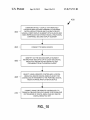
In another aspect of the invention, a method for selecting a
digital media ?le for doWnload or transfer includes the steps
from a Wireless remote controller device and to provide an
adapted to communicate an audio signal to the ?rst audio
ampli?er; a video output port adapted to communicate a
of: (A) communicatively coupling, via a remotely control
lable docking assembly, (1) a portable digital media storage
and playback device having a ?rst display element, With (2)
television-compatible video signal to the second display ele
an audio and video reproduction system having a television
ment; a video processor in communication With the micro
compatible second display element and a ?rst audio ampli?er
adapted to drive at least one speaker, Wherein the docking
assembly comprises (i) a video output port adapted to com
municate a television-compatible video signal to the second
display element, and (ii) a video processor adapted to com
municate to the video output port a television-compatible
video signal indicative of a signal received from the portable
output signal to the microprocessor; an audio output port
processor, the video processor being adapted to communicate
to the video output port a television-compatible video signal
indicative of a signal received from the portable digital media
storage and playback device for display by the second display
element; and a unitary body structure, Wherein the electrical
20
coupling, microprocessor, audio output port, video output
digital media storage and playback device for display by the
second display element, and Wherein the docking assembly
port, and video processor are disposed in or on the unitary
body structure.
In another aspect of the invention, a docking assembly
adapted for use in interfacing (l) a telephonic portable digital
media storage and playback device having a ?rst display
element With (2) a media reproduction system having a ?rst
25
digital media ?le, and (2) a digital media ?le key, as available
for doWnload or transfer to the portable digital media storage
and playback device; and (C) selecting for doWnload or trans
fer of any of the digital media ?le and the digital media ?le
audio ampli?er adapted to drive at least one speaker, com
prises: an electrical coupling adapted to engage the portable
digital media storage and playback device; a microprocessor
adapted to communicate With the portable digital media stor
age and playback device through the electrical coupling; a
remote control receiver adapted to receive an input signal
30
35
and a telephone rebroadcast transceiver adapted to Wirelessly
communicate telephonic signals betWeen (a) the telephonic
portable digital media storage and playback device, and (b)
In another aspect of the invention, a docking assembly
adapted for use in interfacing (l) a telephonic portable digital
media storage and playback device With (2) a media repro
duction system having a ?rst audio ampli?er adapted to drive
at least one speaker, comprises: an electrical coupling adapted
to engage the portable digital media storage and playback
device; a microprocessor adapted to communicate With the
the docking assembly comprises (i) a video output port
40
45
portable digital media storage and playback device through
the electrical coupling; a remote control receiver adapted to
receive an input signal from a Wireless remote controller
the steps of: (A) communicatively coupling, via a remotely
controllable docking assembly, (1) a portable digital media
storage and playback device having a ?rst display element,
With (2) an audio and video reproduction system having a
television-compatible second display element and a ?rst
audio ampli?er adapted to drive at least one speaker, Wherein
to communicate an audio signal to the ?rst audio ampli?er;
the remote controller device.
key using the remote controller.
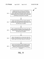
In another aspect of the invention, a method of selecting at
least one digital media ?le for addition to a playlist includes
from a Wireless remote controller device and provide an out
put signal to the microprocessor; an audio output port adapted
has an associated remote controller; (B) identifying on the
second display element information indicative of any of (l) a
50
device and adapted to provide an output signal to the micro
adapted to communicate a television-compatible video signal
to the second display element, and (ii) a video processor
adapted to communicate to the video output port a television
compatible video signal indicative of a signal received from
the portable digital media storage and playback device for
display by the second display element, and Wherein the dock
ing assembly has an associated remote controller; (B) identi
fying on the second display element information indicative of
at least one digital media ?le; and (C) selecting for addition to
a playlist the at least one digital media ?le using the remote
controller.
In another aspect of the invention, a docking assembly is
processor; an audio output port adapted to communicate an
coupleable With a PDMSP device having an electrical cou
audio signal to the ?rst audio ampli?er; and a signal trans
mitter adapted to Wirelessly communicate a signal indicative
pling and an electrical charge storage element, and the dock
of a telephonic signal from the telephonic portable digital
ing assembly comprises: (A) a body having a support element
55
device adapted to control any of a telephonic portable digital
media storage device, a media reproduction system, and a
docking assembly adapted for use in interfacing the tele
phonic portable digital media storage device With the media
reproduction system, comprises: a Wireless signal receiver
adapted to receive a telephonic signal from the docking
assembly; a speaker adapted to reproduce an audible signal
indicative of the received telephonic signal; a voice trans
ducer adapted to produce an electrical vocal output signal; a
and an electrical connector, Wherein the support element is
adapted to receive at least a portion of the portable digital
media storage and playback device, and the electrical con
media storage and playback device to the remote controller
device.
In another aspect of the invention, a remote controller
nector is adapted to simultaneously engage the electrical cou
60
pling When the at least a portion of the portable digital media
storage and playback device is received by the support ele
ment; (B) at least one electrical circuit element adapted to
conduct poWer from an external poWer source to the at least
one electrical coupling for any of (l) poWering the portable
digital media storage and playback device, and (2) charging
65
the electrical charge storage element; and (C) at least one
communication element adapted to communicate a signal
indicative of digital media content played by the portable
US 8,271,713 B2
5
6
digital media storage and playback device to a media signal
reproduction system having an ampli?er and at least one
speaker, Wherein the media reproduction system is adapted to
reproduce the signal indicative of digital media content in
user-perceptible form. Such embodiment may further include
circuitry adapted to control operation of a user-perceptible
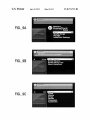
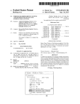
information in an upper portion of the screen, and a settings
menu in a central right port of the screen.
FIG. 9C is a third screen shot taken from a television
compatible display element receiving a signal from a docking
assembly according to the present invention and having a
portable digital media storage device docked thereto, the third
display element.
screen shot shoWing a music menu (inclusive of playlists,
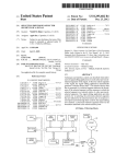
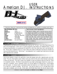
Another aspect of the invention relates to the addition of
authentication elements and steps to the foregoing devices
and methods.
artists, albums, songs, genres, composers, and songbooks
submenus) in a central right port of the screen.
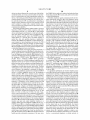
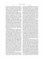
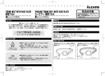
FIG. 10 is a ?owchart of various steps of a method employ
ing a remote controller and a remotely controlled docking
In another aspect of the invention, any of the foregoing
aspects may be combined for additional advantage.
Other aspects, features and embodiments of the invention
Will be more fully apparent from the ensuing disclosure and
assembly as disclosed herein for purchasing digital media
?les and/or digital media ?le keys for doWnload or transfer to
a portable digital media storage device.
FIG. 11 is a ?owchart of various steps of a method employ
ing a remote controller and a remotely controlled docking
appended claims.
assembly as disclosed herein for creating, modifying, and
storing playlists of digital media ?les useable With a portable
digital media storage device.
BRIEF DESCRIPTION OF THE DRAWINGS
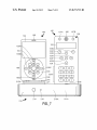
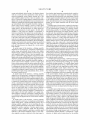
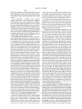
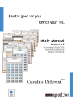
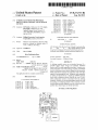
FIG. 1 is a block schematic vieW of a docking assembly
controllable via a remote controller and adapted for use in
20
DETAILED DESCRIPTION OF THE INVENTION,
AND PREFERRED EMBODIMENTS THEREOF
interfacing a portable digital media storage and playback
device With an audio and video reproduction system having a
television-compatible display element, the combination of
elements comprising an entertainment system.
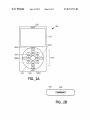
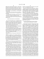
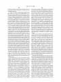
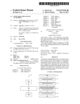
FIG. 2A is a front elevation vieW of a telephonic portable
In certain aspects, the present invention provides a remote
25
digital media storage and playback device.
FIG. 2B is a bottom vieW of the telephonic portable digital
media storage and playback device of FIG. 2A.
FIG. 3 is a schematic vieW of a remote controller device for
30
controlled docking assembly for a portable digital media
storage and playback device that dramatically increases the
utility of a portable digital media storage and playback
(PDMSP) device. A docking assembly according to the
present invention preferably serves as a remotely controllable
interface betWeen a PDMSP device and an audio and video
use With a docking assembly adapted to receive a telephonic
reproduction system having a television-compatible display
portable digital media storage and playback device, the
element Without requiring the use of a personal computer,
While poWering and/or charging the PDMSP device. The
audio and video reproduction system, Which may be disposed
in a stationary (e. g., home) or vehicular environment, enables
digital media ?les such as any of music, photos, videos,
remote controller device having an integral telephone relay
transceiver, a microphone, and a speaker.
FIG. 4A is a front elevation vieW of the remote controller
device of FIG. 3.
FIG. 4B is a bottom vieW of the remote controller device of
FIG. 4A.
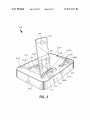
FIG. 5 is a perspective vieW of a docking assembly con
trollable via a Wireless remote controller (such as the control
ler of FIGS. 4A-4B) and adapted for use in interfacing a
35
games, and the like to be reproduced in a form perceptible to
many people. By migrating aWay from a personal computer to
an entertainment system as a primary interface for a PDMSP
40
portable digital media storage and playback device (such as
the portable digital media storage and playback device of
FIGS. 2A-2B) With an audio and video reproduction system
having a television-compatible display element.
45
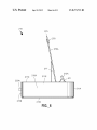
FIG. 6 is a left side elevation vieW of the docking assembly
of FIG. 5.
FIG. 7 is a front vieW ofthe docking assembly ofFIGS. 5-6
certain embodiments include Wired or Wireless netWork con
nectivity, interconnectivity With enhanced remote control
having docked thereto the portable digital media storage and
playback device of FIGS. 2A-2B and the remote controller
device of FIGS. 4A-4B.
components and remote controls for other media system
50
55
FIG. 9A is a ?rst screen shot taken from a television
compatible display element receiving a signal from a docking
assembly according to the present invention and having a
portable digital media storage device docked thereto, the ?rst
screen shot shoWing a Welcome menu in a central right por
tion of the screen.
FIG. 9B is a second screen shot taken from a television
60
compatible display element receiving a signal from a docking
assembly according to the present invention and having a
portable digital media storage device docked thereto, the
devices, and video telephony capabilities.
FIG. 1 illustrates an entertainment system 99 including a
docking assembly 10 remotely controllable via a remote con
troller (preferably a Wireless remote controller, although a
Wired remote controller may be used) and adapted for use in
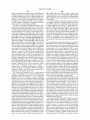
FIG. 8 is a functional block diagram for an authentication
scheme that may be utiliZed by and betWeen a remote con
trolled docking assembly according to the present invention
and a portable digital media storage and playback device.
device, the appeal of a PDMSP device is greatly expanded not
only for the primary user’s sole enjoyment, but also for shar
ing the entertainment experience With groups of users.
Various embodiments provide additional capabilities such
as, for example, telephonic communication, remote con
trolled media ?le purchase and organization, and device
authentication capabilities. Still further features provided in
interfacing a portable digital media storage and playback
(PDMSP) device 80 With an audio and video reproduction
system 2 having a television compatible display element 5, an
(audio) ampli?er 4, and at least one speaker 6. The PDMSP
device 80 has a battery or other charge storage element 81,
and a ?rst display element 82 that is typically a special pur
pose LCD display or a special purpose LED display. Signals
communicated Within the PDMSP device 80 for display by
the ?rst display element 82 are typically formatted for a
65
special purpose ?rst display element 82, and such signals are
typically not television-compatible. The PDMSP device 80
second screen shot shoWing a digital media ?le artist name,
has an onboard memory element, such as a hard disk drive
song title, album name, song play position, and song length
and/or ?ash memory, and is preferably adapted to store and
US 8,271,713 B2
7
8
play back digital audio and video ?les of various formats. The
system 2 (e.g., components such as, but not limited to, the
PDMSP device 80 preferably has at least one electrical con
ampli?er 4 and various media player devices such as a CD or
nector (such as the connector 190 shoWn in FIG. 2B) adapted
to provide an interface for powering and/or charging PDMSP
device 80 as Well as providing communication utility. Com
munication betWeen the PDMSP device 80 and the docking
assembly 10 may also be provided through a headphone or
auxiliary input port 15 optionally provided in or on the dock
DVD changer) or a personal computer, the docking assembly
10 may further include a Wired remote port 23 permitting
communications With a various other media system devices
39. The Wired remote port 23 preferably provides a serial
interface. For example, the Wired remote port 23 may permit
communications With other media or computing devices
ing assembly 10. Such auxiliary input port 15 enables the
according to the EIA232 (formerly RS-232) standard and
disposed remotely relative to the docking assembly 10. Other
communication protocols may be employed as Will be readily
docking assembly 10 to Work With a Wide variety of different
portable digital media storage and playback devices. In one
embodiment, the auxiliary input port 15 comprises a 3.5 mm
diameter female port adapted to receive both audio and video
apparent to one skilled in the art. Utilization of the Wired
remote port 23 interconnected With other independently con
trollable media system device(s) 39 may permit at least cer
signals.
The docking assembly 10, Which preferably comprises a
tain functions of the docking assembly 10 to be controlled
unitary body structure (such as the body structure 210A illus
With a Wireless remote controller other than the Wireless
trated in FIGS. 5-6) has an associated remote controller 50
(preferably a Wireless remote controller) With a battery or
remote controller 50 speci?cally adapted for use With the
docking assembly 10.
other charge storage element 51. The docking assembly 10
may include an internal or external antenna (not shoWn). If
Communication betWeen the docking assembly 10 and
20
Wireless, the remote controller 50 may be adapted to operate
at any desirable frequency of the electromagnetic spectrum.
various data or media networks 40 may be provided by Wired
or Wireless means. For example, the docking assembly 10
may include at least one (Wired) port 25 preferably having an
For example, a Wireless remote controller 50 may include an
appropriate cable terminator and any ?lter or electronic com
infrared and/or a radio frequency (RF) transmitter. Operable
munication equipment (e. g., modem, multiplexer, transceiver
RF frequencies in one embodiment include a range from
25
about 800 MHZ to about 10 GHZ. Any desirable frequency
suitable for Wireless communication of the required band
Width may be used.
The docking assembly 10 has at least one electrical cou
pling 12 adapted to mate With one or more corresponding
connector(s) of the PDMSP device 80, With the at least one
adapted for Ethernet, Fast Ethernet, Gigabit Ethernet, or
l0-Gigabit Ethernet, or other computing device standard
communication protocol for use With a telecommunications
30
electrical coupling optionally including one or more coupling
(s) adapted to mate With one or more corresponding connec
tor(s) of a Wireless remote controller 50. The at least one
electrical coupling 12 preferably includes at least one cou
and/or transducer) appropriate to the cable and communica
tion standard employed. In one embodiment, the port 25 is
netWork 40 that preferably includes connectivity to a distrib
uted netWork such as the World Wide Web and the Internet. In
another embodiment, the port 25 includes a coaxial cable
receptacle and cable modem, or ?ber optic receptacle and
one coupling adapted to mate With a Wireless remote control
multiplexer/demultiplexer, and is adapted for use With a com
puting or media netWork, such as a tWo -Way media netWork of
a cable or satellite telecommunication (e.g., television) pro
vider. In still another embodiment, the port 25 includes a
ler 50. Any coupling of the at least one coupling may protrude
telephonic cable receptacle and telephonic modem and/or
35
pling adapted to mate With the PDMSP device 80, and at least
into or otherWise be disposed in a recess (e.g., recess 272
shoWn in FIG. 5) adapted to receive one of the PDMSP device
80 or the remote controller 50, or may be elevated (e.g., atop
a raised surface portion such as raised surface 271 shoWn in
FIG. 5) relative to an upper surface (e.g., upper surface 211C
shoWn in FIGS. 5-6) of the docking assembly 10.
As illustrated, the docking assembly 10 includes a Wireless
40
In certain embodiment, the docking assembly 10 may
include an integral Wireless netWork transceiver 19 adapted
for communicating With a Wireless netWork 41 that may be
connectable to the Internet and/or World Wide Web. The
45
remote receiver 14, preferably disposed on an exposed front
surface (e.g., front surface 211A shoWn in FIGS. 5-7) of the
netWork, IEEE 802.1l-complaint (Wi-Fi) netWork, an IEEE
802.15.1-compliant (Bluetooth) netWork, or similar or
equivalent netWorks, such as to permit free or paid transfer of
50
14 may be omitted.) The docking assembly 10 may further
55
the same frequency or frequency range as a Wireless remote
controller 50. If provided, positioning the secondary remote
Wireless receiver 38 in signal-receiving proximity to the
remote controller 50 permits the docking assembly 10 to be
placed together With various media system components (e.g.,
the ampli?er 4 and other associated components) in any con
venient or aesthetically pleasing environment, such as in a
cabinet or closet not necessarily disposed in proximity to (or
in a light of sight of) the Wireless remote controller 50.
To provide enhanced remote control capability of, or com
munication capability With additional components, such as
components associated With the audio and video reproduction
digital media ?les, digital media ?le keys, and the like,
betWeen a netWork and the PDMSP device 80 docked With the
docking assembly 10, or betWeen a netWork and a memory
element 44 (e. g., a NAND or other ?ash memory) associated
include a remote Wireless receiver port 22 to Which a second
ary remote Wireless receiver 38 (e. g., a radio frequency or an
infrared receiver) may be communicatively coupled. Such a
secondary remote Wireless receiver 38 preferably operates at
Wireless netWork 41 may include a Wireless local area net
Work (WLAN), such as an IEEE 802.16-compliant (WiMax)
docking assembly 10. (While it is preferred that the remote
controller 50 be Wireless, if such remote controller is a Wired
remote, then it is understood that the Wireless remote receiver
direct subscriber line (DSL) modem to enable communica
tion With a Wired telephonic communication netWork.
60
With the docking assembly 10. Such a netWork 41 may further
include capability to stream stored digital media content
played by the PDMSP device 80 (i.e., When docked to the
docking assembly 10) over the netWork 41 to a netWork
connectable remote device (not shoWn) having an associated
audio and/or video reproduction system. For example, a
PDMSP device 80 may be docked With the docking assembly
80 in a ?rst location in a ?rst room Within a particular facility
65
(e.g., a home or of?ce) having a ?rst audio and video repro
duction system receiving media content from the PDMSP
device via the audio and/or video ports 30, 32, 33 locally
disposed at the docking assembly 10, While media content is
simultaneously broadcast via the Wireless netWork trans
ceiver 19 and the netWork 41 to an appropriate receiving
US 8,271,713 B2
10
device (not shown) disposed in a second room of the facility,
the PDMSP device need not be retrieved and undocked from
outside the facility, or even in a remote facility, for reproduc
the docking assembly 10 to screen, send, and/or receive audio
tion via a second audio and video reproduction system (not
shoWn). The docking assembly 10 may include an internal or
external antenna (not shoWn) adapted for use With the Wire
or data communications.
Preferably, telephonic signals communicated by the tele
phone rebroadcast transceiver 18 to the telephonic remote
less netWork transceiver 19. As an alternative to including an
device (e.g., the device 150) include noti?cation signals and
integral Wireless transceiver 19, the Wired netWork port 25
caller identi?cation information suf?cient to notify the user of
the existence of an incoming call and to provide some iden
may be adapted to connect With a separate Wireless trans
ceiver (not shoWn) providing the same or equivalent Wireless
ti?cation of the caller, so as to enable the user to assess
communication capability.
Whether to accept the incoming call. The telephonic remote
The docking assembly 10 may further include a Universal
Serial Bus (USB) port 25 to enable connection With other
USB-enabled netWorks (e.g., netWork 40) or USB-enabled
device, Which preferably includes a display (e.g., the display
152 illustrated in FIG. 3), preferably includes at least one
communication (e.g., call) noti?cation elements. A commu
nication noti?cation element may provide any user-percep
devices including personal computers or other netWork appli
ances (not shoWn). The USB port may be con?gured to dis
play the docking assembly and/or any PDMSP device 80
tible noti?cation signal, and may provide visible noti?cation,
audible noti?cation, and/or vibratory or other tactile noti?ca
tion of an incoming or received (and stored) communication
docked thereto as a netWork drive, and enable transfer of
media ?les, data, and operable programs or applications
such as a telephone call, text message, email message, video
betWeen the PDMSP device 80 and an interconnected per
message, video conference invitation, digital media ?le, or
the like. Visible noti?cation may be provided via any of the
display 152 (or a portion thereof) and a dedicated LED 156
(as illustrated in FIG. 3) or any other appropriate visible
noti?cation element. Audible noti?cation may be provided by
the speaker 166 (as illustrated in FIG. 3) or a dedicated
sonal computer or netWork appliance (not shoWn). The USB
port 25 may further be used, for example, to enable con?gu
20
ration, updating, or troubleshooting of the docking assembly
10 With a peripheral device such as personal computer, PDA,
or dedicated diagnostic device (not shoWn).
In one embodiment, the docking assembly 10 includes a
Wireless telephone transceiver 18 adapted to rebroadcast tele
phonic signals betWeen a telephone-enabled remote device
(e. g., the telephonic remote controller 150 illustrated in FIG.
3 and FIGS. 4A-4B) and a telephonic PDMSP device (such as
the telephonic PDMSP device 180 illustrated in FIGS.
2A-2B.) Such a telephonic PDMSP device preferably
25
30
audible noti?cation element such as a ringer. Upon noti?ca
tion of an incoming call, the user may elect to receive the call
by activating a user input element 157. The user may further
utiliZe a user input 157 to optionally pause or mute playback
of any digital media stored in the PDMSP device at the time
a call is placed or received.
includes Wireless (e.g., cellular) telephone capability and is
Preferably, digital media ?les may be played by, or stored
to, a telephonic PDMSP device While the telephonic PDMSP
adapted to execute any of various conventional portable tele
device (e.g., device 180) is sending or receiving telephonic
phone functions such as sending or receiving telephone calls,
sending or receiving data such as email or text messages,
signals (i.e., enabling the user to engage in a telephone call)
35
connecting to Wireless data netWorks, and the like. The term
“rebroadcast” in the context of the Wireless telephone trans
ceiver 18 refers to the capability to retransmit or otherWise
PDMSP and a remote telephonic device (e. g., remote control
ler device 150).
relay incoming telephonic signals from a telephonic PDMSP
device to a Wireless telephonic device (e.g., the telephonic
remote controller 150) and to similarly receive incoming
signals from the Wireless telephonic device for forWarding to
a transmitter portion of the telephonic PDMSP device. The
Wireless telephone (rebroadcast) transceiver 18 associated
With the docking assembly 10 preferably operates at the same
frequency or frequencies as the telephone transceiver 158
associated With a telephonic remote controller device (e.g.,
40
45
In a preferred embodiment, the Wireless telephone trans
ceiver 18 is distinct from the Wireless remote receiver 14, With
such elements operating at different frequencies, to permit
telephonic and remote control functions to be performed
independently from one another. In another embodiment, the
Wireless remote receiver 14 may be integrated With the Wire
less telephone transceiver 18 (or at least a receiver portion
thereof), With the telephonic and remote control functions
utiliZing a common frequency range. Such embodiment may
the device 150). Any suitable frequency range may be used,
Whether analog or digital, and Whether ?xed frequency or
spread spectrum. Preferably, such transceivers 18, 158 oper
and the docking assembly 10 is simultaneously engaged in
rebroadcast communication of telephonic signals betWeen
50
ate at a frequency range of from about 800 MHZ to about 10
promote economies of cost and siZe in the docking assembly
10 and the telephonic remote controller 150 (as illustrated in
FIG. 3 and FIGS. 4A-4B).
A camera port 26 may be provided in the docking assembly
GHZ, speci?cally including the frequencies of any of 900
10 to permit interconnection of a camera device 42, such as
MHZ, 1.9 GHZ, 2.4 GHZ, and 5.8 GHZ. The term “trans
may be useful for video telephony and/or to capture video
ceiver” in this context refers to any combination of transmitter
and receiver present in the same device (e.g., PDMSP device
or remote controller device), Whether or not such components
are integrated at the microchip level. The Wireless telephone
transceiver 18 associated With the docking assembly 10 thus
transfers user input and output telephonic functions in a
seamless fashion from the telephonic PDMSP device (e.g.,
55
or other suitable memory format) associated With the docking
assembly 10. The camera device 42 may be integrated into a
60
PDMSP device 180) to a telephone-enabled remote device
the docking assembly 10, but more preferably the camera
device 42 is separate from the docking assembly 10 to permit
the camera device 42 to be placed in any appropriate position
for the desired end use. In one embodiment, the camera
device 42 comprises a Wireless receiver for use With a Wire
(e. g., the telephonic remote controller 150) While the PDMSP
device is docked With the docking assembly 10, With signals
betWeen the PDMSP device and docking assembly 10 pref
erably being routed through the at least one electrical cou
pling 12 and mated connector 180. Such telephonic function
transfer provides substantial convenience to the user, since
footage of an event for recordation in the PDMSP device 80
and/or a memory device 44 (e.g., a hard drive, ?ash memory,
less camera device (not shoWn), thus providing enhanced
65
freedom in camera placement for the desired end use. The
camera device 42 is preferably adapted to output a com
pressed data format suitable for transmission over a netWork,
such as a conventional telephonic or cellular netWork, to
US 8,271 ,713 B2
11
12
enable video telephony. In a preferred embodiment, the out
various audio and video output modes, or betWeen any of
various audio or video output formats), and the like. OWing to
put format and/ or data output rate of the camera device 42 is
user-con?gurable to provide an output appropriately tailored
to the memory available, network limitations, and/or desired
end use.
the enhanced functionality provided by a Wireless remote
controller device 50, hoWever, local controls 17 may be mini
miZed in functionality or eliminated altogether if desired.
In one embodiment, a telephonic remote controller
includes a camera (e.g., a video camera) and is adapted to
docking status, communication status, and the like may be
Local indication of basic functionality such as poWer on,
send and receive video signals, With received video signals
being displayable locally at the telephonic remote controller
provided With one or more LEDs 16, Which are preferably
disposed on an outWardly visible portion (e.g., the front sur
face) of the docking assembly 10. Multiple LEDs or a smaller
number of multi-color LEDs may be employed to provide
different status indications, if desired.
A primary function of the docking assembly 10 is to serve
(e.g., the controller 150 illustrated in FIG. 3 and FIGS.
4A-4B) on the display element 152 to permit video telephony.
Preferably, user inputs associated With the telephonic remote
controller may be used to enable audio and video reproduc
tion via the local speaker 166 plus local display element 152
as an audio/video interface betWeen a PDMSP device 80
and/ or on the television-compatible display element 5 that is
docked thereto and an audio and video reproduction system 2
associated With the audio and video reproduction system 2
communicatively linked to a telephonic PDMSP device (e.g.,
having a television-compatible display element 5. Signals
(e.g., audio signals, video signals, both audio and video sig
nals, and/or other types of signals) may be communicated
the device 180) via the docking assembly 10.
The docking assembly 10 of FIG. 1 employs various ele
ments requiring direct current (DC) poWer, such as the micro
processor 45. To adapt the docking assembly 10 for use With
an alternating current (AC) poWer source 35, a sWitching
20
coupling 12. The microprocessor 45 preferably communi
(e. g., recti?ed) poWer supply 36 (Which is preferably external
to the docking assembly 10) is interposed betWeen the AC
poWer source 35 and a poWer port 20 provided in the docking
assembly 10. In one embodiment, a DC poWer adapter (not
betWeen the PDMSP device and the microprocessor 45 of the
docking assembly 10 by Way of the at least one electrical
25
cates With a video processor 46, a digital signal processor 48,
and an ampli?er 49. In turn, the video processor 46 is com
municatively coupled to at least one video port 32 and pref
erably at least one audio/video port 33 coupleable to the
audio/video reproduction system 2. The digital signal proces
shoWn) may be substituted for the poWer supply 36 to adapt
the docking assembly 10 to a DC poWer source such as may be
sor 48 (Which may be used, for example, to add equalization
present in an automobile, recreational vehicle, airplane, or
similar mobile environment having an audio and video repro
duction system 2. Within the docking assembly, a poWer
distribution bus 21 provides poWer at voltages and current
levels appropriate to various internal elements, as shoWn With
dashed lines internal to the docking assembly 10 in FIG. 1.
Internal to the docking assembly 10, at least one charging
element 43 is provided to fumish poWer at appropriate levels
and/or sound ?eld effects to an audio signal stream) commu
nicates an audio stream to an ampli?er 45 (internal to the
30
docking assembly 10) adapted to adjust the output level of the
audio signal to at least one audio port 30 and the audio portion
of at least one audio/video port 33 coupleable to the audio/
35
such as may be received via the Wireless remote receiver 14
from the Wireless remote controller 50, or received via the
to poWer the PDMSP device 80 and Wireless remote control
ler device 50 and/ or charge the batteries associated With the
devices 80, 50 When such devices 80, 50 are docked With the
docking assembly 10 via the at least one electrical coupling
40
12. The at least one charging element 43 includes at least one
electrically conductive circuit element, With appropriate cur
rent transducers preferably provided to sense and permit
regulation of current How so as to minimize the possibility of
overcharging the battery 81 associated With the docked
PDMSP device 80 and/or the battery 51 associated With the
video reproduction system 2. The output signal level of the
ampli?er 49 is preferably responsive to a volume input signal,
local user controls 17 (if provided). Various digital-to-analog
signal converters (not shoWn) may be integrated into any of
the video processor 46, digital signal processor 48, and
microprocessor 45, or provided doWnstream of such compo
nents, if desired to generate analog output signals from the
digital media signal provided by the PDMSP device 80. The
microprocessor 45 and/ or video processor 46 may further be
45
remote controller device 50. The charging element 43 and/or
used to provide video format conversion utility (e.g., from
non-television-compatible formats to television-compatible
formats) and to generate any desirable visual output signals
at least one electrical coupling 12 may further include an
(e.g., still images, video images, and/or computer generated
associated temperature transducer such as a thermistor or
display applications such as screensavers, skins, and other
thermocouple (not shoWn) to provide thermal feedback suit
able for regulating electrical charge supplied to the batteries
50
audio playback) during the playback of a digital audio ?le
stored in a docked PDMSP device 80.
81, 51 of the docked device(s) 80, 50. In one embodiment,
electrical charge is supplied to the docked PDMSP device 80
Each of the digital signal processor 48 and video processor
46 may include general-purpose or specialty microprocessor
and/or remote controller device 50 at a ?rst rate While such
device batteries 81, 51 are charging, and then supplied at a
second, loWer “maintenance” rate When such devices batter
ies 81, 51 are fully charged to poWer the devices 80, 50
Without overcharging their batteries 81, 51. When such bat
teries 81, 51 are fully charged, the charging element 43 may
be used to assist in poWering the PDMSP device 80.
The docking assembly 10 may include various local user
55
device 80 on the one hand and the video processor 46, digital
signal processor 48, and ampli?er 49 on the other, it is to be
appreciated that communication paths independent of the
60
microprocessor 45 (but preferably sWitchably controlled by
65
the microprocessor) may be provided betWeen the PDMSP
device 80 and any of the video processor 46, digital signal
processor, and ampli?er 49, if desired. Alternatively, any of
the video processor 46 and the digital signal processor 48 may
be integrated, in Whole or in part, With the (central) micro
surface of the assembly) adapted to control the docking
or sWitch (e.g., to permit a user to select betWeen any of
chips. While FIG. 1 illustrates the microprocessor 45 as inter
mediately disposed in communication betWeen the PDMSP
controls 17 (e.g., disposed on a front, top, or other accessible
assembly and/or certain functions of a PDMSP device 80
docked thereto. Examples of local controls include poWer
buttons or sWitches, volume buttons, a mode selector button
visualiZations, Whether or not synchroniZed or responsive to
processor 45. The video processor 46 preferably has an asso
ciated frame buffer adapted to store an image to be transmit
US 8,271 ,713 B2
13
14
ted to the at least one video port 32 and/or the at least one
Songs, Genres, Composers, and Songbooks. In each instance,
audio/video port 33 for transmission to the audio and video
the user-selectable options are selectable With a remote con
reproduction system 2.
troller device, such as the devices 50, 150 described herein.
The screen shots depicted in FIGS. 9A-9C are merely illus
A PDMSP device 80 may communicate, through an inter
face connector (e.g., the connector 190 illustrated in FIG.
2B), various types of signals to an accessory device, such as
trative of certain menus according to one embodiment of the
invention. Various other menus and displays of static or
the docking assembly 10. Examples of such signal types may
include, for example: (a) signals indicative of menu contents;
(b) signals containing digital media ?le or digital media ?le
key identi?ers; (c) digital media ?le content; (d) control sig
dynamic information may be provided. In one embodiment,
at least a portion of a television-compatible display element 5
displays visual media such as album art, music videos, visu
aliZation patterns (Whether or not synchronized to music
playback), digital skins, or other user-selected images or vid
eos simultaneous With playback of digital music from a
PDMSP device (e. g., PDMSP device 80 or 180) docked With
nals; (e) status signals, and so on. Such signals are typically
not communicated through the interface connector by the
PDMSP device 80 in a television-compatible form. As noted
the docking assembly (e.g., docking assembly 10 or 210).
previously, signals communicated Within the PDMSP device
80 for display by the ?rst display element 82 are typically
formatted for a special purpose ?rst display element 82, and
patible (e.g., NTSC, PAL, various conventional high de?ni
tion television formats, or equivalent signal standards) signals
Such visual media may be stored on the PDMSP device itself,
stored in a memory 44 associated With the docking assembly
10, or automatically retrieved over a netWork (e.g., netWork
19 or 40) upon initiation of playback of an audio ?le. In one
embodiment, the displayable visual media includes a list of
digital media ?les selectable for retrieval or doWnload, such
as for a fee. In further embodiments, the displayable visual
media may include other subscription-based media, commer
communicable to a television-compatible display element 5
cial programming, or commercial (e.g., product or service)
not for a television-compatible display element. Desirable
functions of the microprocessor 45 and/ or video processor 46
Within the docking assembly 10 include processing signals
received from the PDMSP device 80 to yield television com
20
offerings.
through the at least one video port 32 and/or at least one
audio/video port 33. This may be accomplished, for example,
25
by developing television-compatible display menus, storing
the same Within the docking assembly 10 (e. g., in the memory
element 44), populating the display menus With digital signal
data received from the PDMSP device 80, and providing the
populated display menus as a television-compatible signal to
Display menus in television-compatible form generated or
otherWise provided by the docking assembly 10 may be sub
stantially static in character With substantially still images
(e.g., With the exception of audio ?le playback time or time
remaining), or the display menus may include dynamic
30
images, such as to prevent burn-in of a screen image, or to
the at least one video port 32 and the at least one audio-video
display images (such as digital “skins”) selected for visual
port 33. With the PDMSP device 80 adapted to display an
aggregate ?rst set of information With ?rst display element 82
When the device 80 is inuse, the docking assembly 10 (includ
ization With playback of a digital audio ?le. Alternatively, one
or more digital photographic images embodying still pic
ing the video processor 46) is preferably adapted to generate
a substantially complete replicate of the ?rst set of informa
tion on the television-compatible display element 5 When the
PDMSP device 80 is docked With the docking assembly 10.
For example, the docking assembly 10 and video processor
46 are preferably adapted to output a television-compatible
video signal containing any of the following: (1) count of any
tures, digital video images embodying moving pictures, com
35
skins, other visualiZations, and/or games) stored on the
PDMSP device 80 may be displayed through the second
display element 5 When the PDMSP is communicatively
docked With the docking assembly 10. In still another alter
40
names of any of playlists, artists, albums, genre, songs, and
composers; (3) current play status embodying any of song
45
current song status embodying any of song name, artist name,
and album name.
Screen shots taken from a television-compatible display
element shoWing populated menus output from a docking
assembly according to the present invention and having a
as depicted in FIG. 9A, are trademarks of Netalog, Inc.
(Durham, NC). The second screen shot depicted in FIG. 9B
shoWs a digital media ?le artist name, song title, album name,
song play position, and song length information in an upper
portion of the screen, and a settings menu in a central right
port of the screen. The setting menu includes the folloWing
55
60
user-selectable options: Color Themes, Screen Savers,
Screen Saver Time, and About HomeDock. The third screen
shot depicted in FIG. 9C shoWs a music menu in a central
right port of the screen, With the music menus including the
folloWing user-selectable options: Playlists, Artists, Albums,
television-compatible display element communicatively con
nected to the docking assembly.
At least one video signal output from the docking assembly
10 is preferably digital, although digital-to-analog signal con
version may be performed as part of processing video signals
as appropriate to the desired output format. Audio signals
50
PDMSP device communicatively docked thereto are pro
vided in FIGS. 9A-9C. The ?rst screen shot depicted in FIG.
9A shoWs a Welcome menu in a central right portion of the
screen, listing the folloWing user-selectable options: Menu,
Shuf?e Songs, Playlists, and HomeDock® Settings. It is
noted that “HomeDock,” “HomeDock Deluxe,” and “DLO,”
native embodiment, digital images, digital video images, and/
or computer-generated display applications may be stored in
a docking assembly (e.g., in memory element 44 illustrated in
FIG. 1) according to the present invention for playback on a
of playlists, artists, albums, genre, songs, and composers; (2)
length, song position, and play/pause/ stop status; and (4)
puter-generated display applications (e.g., screensavers,
65
emanating from the PDMSP device 80, Whether such signals
are in substantially unaltered or processed (e. g., by Way of the
digital signal processor 48 and/or any digital-to-analog con
verters) form, are further communicated to the at least one
audio port 30 and the at least one audio/video port 33.
Each of the at least one audio port 30, the at least one video
port 32, and the at least one audio/video port 33 preferably
includes multiple connectors to provide an appropriate level
of ?delity and compatibility With various external devices in
a given user’s audio and video reproduction system 2.
Examples of suitable connectors include, but are not limited
to, ?ber optic connectors, coaxial connectors, RG-6 coaxial
connectors, RCA plug connectors, S-video connectors, com
posite video connectors, Digital Visual Interface (DVI) con
nectors, High De?nition Multimedia Interface (HDMITM)
connectors, SCART connectors, Uni?ed Display Interface
connectors, and DisplayPort connectors. Audio and video
signals may be conveyed via discrete connectors, or inte