1
Cat. No. 01016428
Rev. A 12/08/04
DCO # 5525
Problem Water
Reference Manual
©2004 Culligan International Company
CONFIDENTIAL
Printed in USA
This manual is intended to provide general information only and should not be construed as advice,
particularly as it relates to specific situations. You are encouraged to seek the advice of your own
advisors with respect to the matters discussed herein. Local conditions and requirements will vary. It
is your responsibility to be familiar with and comply with all applicable laws and regulations. Culligan
International Company shall have no liability arising from any use of this information.
CONFIDENTIAL For use only in connection with the Culligan system May not be reproduced without permission All marks
herein are trademarks of Culligan International Company
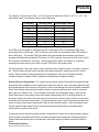
!
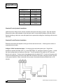
WARNING! Problem water treatment occasionally requires the use of chemicals, some of
which are hazardous or toxic. To the extent possible, chemical usage should be minimized or
avoided, particularly in residential applications.
•
Culligan dealers are advised to encourage customers to have their systems professionally
maintained, including the handling and replenishment of all chemicals, through a service contract
with the local Culligan dealer.
•
Where chemical usage is necessary and where consumers elect to store, handle and/or use water
treatment chemicals themselves, Culligan dealers are advised to strongly caution consumers about
potential hazards and to furnish Material Safety Data Sheets (MSDS) on any chemicals they provide.
•
When using chemicals, always follow the manufacture recommendation for the use of appropriate
personal protective equipment as noted in the MSDS for that chemical
Table of Contents
CHAPTER 1 - INTRODUCTION TO PROBLEM WATER
Definitions of Problem Water . . . . . . . . . . . . . . . . . . . . . . . . . . . . . . . . . . . . . . . . . . . . . . . . . . . . . . . . . . . . . . . . . . . . . . . .3
The Problem Water Market . . . . . . . . . . . . . . . . . . . . . . . . . . . . . . . . . . . . . . . . . . . . . . . . . . . . . . . . . . . . . . . . . . . . . . . . .4
Problem Water Is Different . . . . . . . . . . . . . . . . . . . . . . . . . . . . . . . . . . . . . . . . . . . . . . . . . . . . . . . . . . . . . . . . . . . . . . . . .4
Approaching Problem Water
. . . . . . . . . . . . . . . . . . . . . . . . . . . . . . . . . . . . . . . . . . . . . . . . . . . . . . . . . . . . . . . . . . . . . . .5
CHAPTER 2 - PROBLEMS AND CAUSES
Quick Reference Guide . . . . . . . . . . . . . . . . . . . . . . . . . . . . . . . . . . . . . . . . . . . . . . . . . . . . . . . . . . . . . . . . . . . . . . . . . . . .7
CHAPTER 3 - CAUSES OF WATER PROBLEMS
Acidity and Alkalinity . . . . . . . . . . . . . . . . . . . . . . . . . . . . . . . . . . . . . . . . . . . . . . . . . . . . . . . . . . . . . . . . . . . . . . . . . . . . . .9
Aluminum . . . . . . . . . . . . . . . . . . . . . . . . . . . . . . . . . . . . . . . . . . . . . . . . . . . . . . . . . . . . . . . . . . . . . . . . . . . . . . . . . . . . . .11
Arsenic . . . . . . . . . . . . . . . . . . . . . . . . . . . . . . . . . . . . . . . . . . . . . . . . . . . . . . . . . . . . . . . . . . . . . . . . . . . . . . . . . . . . . . . .12
Asbestos . . . . . . . . . . . . . . . . . . . . . . . . . . . . . . . . . . . . . . . . . . . . . . . . . . . . . . . . . . . . . . . . . . . . . . . . . . . . . . . . . . . . . .13
Barium . . . . . . . . . . . . . . . . . . . . . . . . . . . . . . . . . . . . . . . . . . . . . . . . . . . . . . . . . . . . . . . . . . . . . . . . . . . . . . . . . . . . . . . .13
Cadmium . . . . . . . . . . . . . . . . . . . . . . . . . . . . . . . . . . . . . . . . . . . . . . . . . . . . . . . . . . . . . . . . . . . . . . . . . . . . . . . . . . . . . .14
Chloride . . . . . . . . . . . . . . . . . . . . . . . . . . . . . . . . . . . . . . . . . . . . . . . . . . . . . . . . . . . . . . . . . . . . . . . . . . . . . . . . . . . . . . .14
Chlorine . . . . . . . . . . . . . . . . . . . . . . . . . . . . . . . . . . . . . . . . . . . . . . . . . . . . . . . . . . . . . . . . . . . . . . . . . . . . . . . . . . . . . . .15
Chromium . . . . . . . . . . . . . . . . . . . . . . . . . . . . . . . . . . . . . . . . . . . . . . . . . . . . . . . . . . . . . . . . . . . . . . . . . . . . . . . . . . . . . .16
Copper . . . . . . . . . . . . . . . . . . . . . . . . . . . . . . . . . . . . . . . . . . . . . . . . . . . . . . . . . . . . . . . . . . . . . . . . . . . . . . . . . . . . . . . .16
Detergent . . . . . . . . . . . . . . . . . . . . . . . . . . . . . . . . . . . . . . . . . . . . . . . . . . . . . . . . . . . . . . . . . . . . . . . . . . . . . . . . . . . . . .17
Dissolved gasses . . . . . . . . . . . . . . . . . . . . . . . . . . . . . . . . . . . . . . . . . . . . . . . . . . . . . . . . . . . . . . . . . . . . . . . . . . . . . . . .18
Fluoride . . . . . . . . . . . . . . . . . . . . . . . . . . . . . . . . . . . . . . . . . . . . . . . . . . . . . . . . . . . . . . . . . . . . . . . . . . . . . . . . . . . . . . .19
Hardness . . . . . . . . . . . . . . . . . . . . . . . . . . . . . . . . . . . . . . . . . . . . . . . . . . . . . . . . . . . . . . . . . . . . . . . . . . . . . . . . . . . . . .19
Hydrogen Sulfide . . . . . . . . . . . . . . . . . . . . . . . . . . . . . . . . . . . . . . . . . . . . . . . . . . . . . . . . . . . . . . . . . . . . . . . . . . . . . . . .20
Iron . . . . . . . . . . . . . . . . . . . . . . . . . . . . . . . . . . . . . . . . . . . . . . . . . . . . . . . . . . . . . . . . . . . . . . . . . . . . . . . . . . . . . . . . . . .22
Lead . . . . . . . . . . . . . . . . . . . . . . . . . . . . . . . . . . . . . . . . . . . . . . . . . . . . . . . . . . . . . . . . . . . . . . . . . . . . . . . . . . . . . . . . . .23
Manganese . . . . . . . . . . . . . . . . . . . . . . . . . . . . . . . . . . . . . . . . . . . . . . . . . . . . . . . . . . . . . . . . . . . . . . . . . . . . . . . . . . . .23
Mercury . . . . . . . . . . . . . . . . . . . . . . . . . . . . . . . . . . . . . . . . . . . . . . . . . . . . . . . . . . . . . . . . . . . . . . . . . . . . . . . . . . . . . . .24
Microorganisms . . . . . . . . . . . . . . . . . . . . . . . . . . . . . . . . . . . . . . . . . . . . . . . . . . . . . . . . . . . . . . . . . . . . . . . . . . . . . . . . .25
Nitrate/Nitrite . . . . . . . . . . . . . . . . . . . . . . . . . . . . . . . . . . . . . . . . . . . . . . . . . . . . . . . . . . . . . . . . . . . . . . . . . . . . . . . . . . .26
Petroleum . . . . . . . . . . . . . . . . . . . . . . . . . . . . . . . . . . . . . . . . . . . . . . . . . . . . . . . . . . . . . . . . . . . . . . . . . . . . . . . . . . . . . .27
Radionuclides . . . . . . . . . . . . . . . . . . . . . . . . . . . . . . . . . . . . . . . . . . . . . . . . . . . . . . . . . . . . . . . . . . . . . . . . . . . . . . . . . . .28
Selenium . . . . . . . . . . . . . . . . . . . . . . . . . . . . . . . . . . . . . . . . . . . . . . . . . . . . . . . . . . . . . . . . . . . . . . . . . . . . . . . . . . . . . .29
Silica . . . . . . . . . . . . . . . . . . . . . . . . . . . . . . . . . . . . . . . . . . . . . . . . . . . . . . . . . . . . . . . . . . . . . . . . . . . . . . . . . . . . . . . . . .29
Sodium . . . . . . . . . . . . . . . . . . . . . . . . . . . . . . . . . . . . . . . . . . . . . . . . . . . . . . . . . . . . . . . . . . . . . . . . . . . . . . . . . . . . . . . .30
Strontium . . . . . . . . . . . . . . . . . . . . . . . . . . . . . . . . . . . . . . . . . . . . . . . . . . . . . . . . . . . . . . . . . . . . . . . . . . . . . . . . . . . . . .32
Sulfate . . . . . . . . . . . . . . . . . . . . . . . . . . . . . . . . . . . . . . . . . . . . . . . . . . . . . . . . . . . . . . . . . . . . . . . . . . . . . . . . . . . . . . . .33
Suspended Solids . . . . . . . . . . . . . . . . . . . . . . . . . . . . . . . . . . . . . . . . . . . . . . . . . . . . . . . . . . . . . . . . . . . . . . . . . . . . . . .33
Tannins . . . . . . . . . . . . . . . . . . . . . . . . . . . . . . . . . . . . . . . . . . . . . . . . . . . . . . . . . . . . . . . . . . . . . . . . . . . . . . . . . . . . . . . .34
Total Dissolved Solids . . . . . . . . . . . . . . . . . . . . . . . . . . . . . . . . . . . . . . . . . . . . . . . . . . . . . . . . . . . . . . . . . . . . . . . . . . . .35
Turbidity . . . . . . . . . . . . . . . . . . . . . . . . . . . . . . . . . . . . . . . . . . . . . . . . . . . . . . . . . . . . . . . . . . . . . . . . . . . . . . . . . . . . . . .36
Volatile Organic Chemicals . . . . . . . . . . . . . . . . . . . . . . . . . . . . . . . . . . . . . . . . . . . . . . . . . . . . . . . . . . . . . . . . . . . . . . . .36
Zinc . . . . . . . . . . . . . . . . . . . . . . . . . . . . . . . . . . . . . . . . . . . . . . . . . . . . . . . . . . . . . . . . . . . . . . . . . . . . . . . . . . . . . . . . . .37
©2004 Culligan International Company
CONTENTS 1
Table of Contents
CHAPTER 4 - TESTING
Laboratory Water Analysis . . . . . . . . . . . . . . . . . . . . . . . . . . . . . . . . . . . . . . . . . . . . . . . . . . . . . . . . . . . . . . . . . . . . . . . . .39
Field Testing . . . . . . . . . . . . . . . . . . . . . . . . . . . . . . . . . . . . . . . . . . . . . . . . . . . . . . . . . . . . . . . . . . . . . . . . . . . . . . . . . . . .44
CHAPTER 5 - PRODUCTS
Softeners . . . . . . . . . . . . . . . . . . . . . . . . . . . . . . . . . . . . . . . . . . . . . . . . . . . . . . . . . . . . . . . . . . . . . . . . . . . . . . . . . . . . . .51
Chloride Anion Resin Systems . . . . . . . . . . . . . . . . . . . . . . . . . . . . . . . . . . . . . . . . . . . . . . . . . . . . . . . . . . . . . . . . . . . . . .57
Deionizers . . . . . . . . . . . . . . . . . . . . . . . . . . . . . . . . . . . . . . . . . . . . . . . . . . . . . . . . . . . . . . . . . . . . . . . . . . . . . . . . . . . . .63
Carboxylic Systems . . . . . . . . . . . . . . . . . . . . . . . . . . . . . . . . . . . . . . . . . . . . . . . . . . . . . . . . . . . . . . . . . . . . . . . . . . . . . .64
Neutralizers . . . . . . . . . . . . . . . . . . . . . . . . . . . . . . . . . . . . . . . . . . . . . . . . . . . . . . . . . . . . . . . . . . . . . . . . . . . . . . . . . . . .65
Activated Carbon Filters . . . . . . . . . . . . . . . . . . . . . . . . . . . . . . . . . . . . . . . . . . . . . . . . . . . . . . . . . . . . . . . . . . . . . . . . . . .67
Particulate Filters . . . . . . . . . . . . . . . . . . . . . . . . . . . . . . . . . . . . . . . . . . . . . . . . . . . . . . . . . . . . . . . . . . . . . . . . . . . . . . . .71
Oxidizing Filters . . . . . . . . . . . . . . . . . . . . . . . . . . . . . . . . . . . . . . . . . . . . . . . . . . . . . . . . . . . . . . . . . . . . . . . . . . . . . . . . .75
Reverse Osmosis Systems . . . . . . . . . . . . . . . . . . . . . . . . . . . . . . . . . . . . . . . . . . . . . . . . . . . . . . . . . . . . . . . . . . . . . . . .80
Ultraviolet Systems . . . . . . . . . . . . . . . . . . . . . . . . . . . . . . . . . . . . . . . . . . . . . . . . . . . . . . . . . . . . . . . . . . . . . . . . . . . . . .88
Cul-Cleer™ Systems . . . . . . . . . . . . . . . . . . . . . . . . . . . . . . . . . . . . . . . . . . . . . . . . . . . . . . . . . . . . . . . . . . . . . . . . . . . . .90
Aeration Systems . . . . . . . . . . . . . . . . . . . . . . . . . . . . . . . . . . . . . . . . . . . . . . . . . . . . . . . . . . . . . . . . . . . . . . . . . . . . . . .101
APPENDICES
Chemicals Used In Water Treatment . . . . . . . . . . . . . . . . . . . . . . . . . . . . . . . . . . . . . . . . . . . . . . . . . . . . . . . . . . . . . . . .103
Sodium Content . . . . . . . . . . . . . . . . . . . . . . . . . . . . . . . . . . . . . . . . . . . . . . . . . . . . . . . . . . . . . . . . . . . . . . . . . . . . . . . .105
Langlier Saturation Index . . . . . . . . . . . . . . . . . . . . . . . . . . . . . . . . . . . . . . . . . . . . . . . . . . . . . . . . . . . . . . . . . . . . . . . . .106
pH Calculations – Reverse Osmosis and Dealkalizer Systems
. . . . . . . . . . . . . . . . . . . . . . . . . . . . . . . . . . . . . . . . . . .108
US EPA Drinking Water Standards . . . . . . . . . . . . . . . . . . . . . . . . . . . . . . . . . . . . . . . . . . . . . . . . . . . . . . . . . . . . . . . . . .110
Retention Tank Design . . . . . . . . . . . . . . . . . . . . . . . . . . . . . . . . . . . . . . . . . . . . . . . . . . . . . . . . . . . . . . . . . . . . . . . . . . .118
Well Pump Flow Rate . . . . . . . . . . . . . . . . . . . . . . . . . . . . . . . . . . . . . . . . . . . . . . . . . . . . . . . . . . . . . . . . . . . . . . . . . . . .122
Conversion Factors . . . . . . . . . . . . . . . . . . . . . . . . . . . . . . . . . . . . . . . . . . . . . . . . . . . . . . . . . . . . . . . . . . . . . . . . . . . . . .122
Ironeater™ Chemical Feed System . . . . . . . . . . . . . . . . . . . . . . . . . . . . . . . . . . . . . . . . . . . . . . . . . . . . . . . . . . . . . . . . .123
2
CONTENTS
©2004 Culligan International Company
Chapter 1
Chapter 1
Introduction To Problem Water
Definition of Problem Water
Since "problem water" is the subject of this manual, the best way to start is to define what it is. In the past,
problem water was loosely defined as, "water requiring a treatment more complex than simple softening."
Consider the following two definitions:
1. Problem water is water with one or more of the following symptoms:
•
looks bad
•
smells bad
•
tastes bad
•
causes staining/spotting
•
causes corrosion
•
causes personal appearance problems
2. Problem water is water that contains contaminants that do not meet the standards for a particular
application.
The first definition often is the one used by the potential customer, who calls you and reports problems like a
yellow color, a rotten egg odor, a salty taste, white spotting, or even green hair.
The second definition is the one often used by water treatment professionals. Although the standards may
include contaminants known to cause the problems observed by the potential customer, they might also include
contaminants causing problems that are not immediately obvious. Perhaps the most common of these "hidden"
contaminants is nitrate. It does not cause a look/smell/taste problem, but it may cause health problems for
infants, elderly, and immune-compromised individuals.
Which definition should you use? BOTH!
Talk to the customer regarding the problems he or she has identified. Add this information to your own
observations. If you do not talk to the customer, you might install equipment that will solve a problem that you
identified, but not a problem that the customer identified.
The most common water standards used in the problem water market are the U.S. EPA National Drinking Water
Standards (see Appendix). However, there may be other standards more appropriate to a particular application,
such as state drinking water standards, beverage water standards, or agriculture water standards. Be certain you
know the standards that are appropriate for the application. In some cases, the customer must provide these
standards.
©2004 Culligan International Company
INTRODUCTION TO PROBLEM WATER 3
Introduction To Problem Water
The Problem Water Market
There are four primary sources of water used in most homes and commercial applications. Each source has
commonly occurring contaminants.
• Private well sources often contain iron and/or hydrogen sulfide.
• Municipal well sources often contain free chlorine and may cause corrosion.
• Private surface water sources often contain microorganisms and sediment, and may cause corrosion.
• Municipal surface water sources often contain free chlorine, chloramines, and fine particles, and may cause
corrosion.
Private well supplies traditionally are considered the primary problem water market, but all the sources have
market potential if the proper approach is used.
Problem Water Is Different
Some salespeople are reluctant to enter the problem water market because of problems encountered in previous
applications. Some caution is good, since many problems have been caused by rushing to conclusions regarding
the type of problem, its cause, and the water treatment required. Problem water applications are not the same as
"simple softener" applications:
• The customer realizes there is a problem with the water. In a sense, water treatment equipment already has
been sold. The questions are what treatment will be sold and who will sell it.
• Technical skills are as important, and often more important, than sales skills. Even those customers with no
knowledge of water treatment often can tell when a sales representative is not comfortable answering
questions about their problem water.
• The possibility of misapplication is greater. Often there are many potential causes of a particular problem.
Each cause may require a different kind of water treatment, so it is extremely important to try to find out what is
causing the problem.
• The customer is more demanding. For simple softening applications, there are many cases where the
customer did not report a problem even though the softener had not been working for years. It is not likely that
a customer will ignore iron stains, rotten-egg odor, etc., for very long.
• Although the risks are greater, the reward of being recognized as a Problem Water Expert more than
compensates. Most problem water markets are rural or small-municipal, and word-of-mouth can be very
important. Success in the problem water market can lead to increased sales in other markets.
This manual is intended to provide technical expertise in problem water applications so that you will make the
sale, avoid mis-applications, and enhance your reputation as an expert in problem water markets.
4 INTRODUCTION TO PROBLEM WATER
©2004 Culligan International Company
Introduction To Problem Water
Approaching Problem Water
Go back and read the two definitions of problem water. Each definition leads to a different approach. The first
can be termed the "IDEA" approach:
Step 1. Identify the problem(s).
Talk to the customer! Look at, smell, and taste the water. Examine fixtures for corrosion or staining.
Step 2. Develop a theory regarding the cause of a problem.
For example, blue-green stains might be caused by copper corrosion.
Step 3. Examine the water to determine if the theory is valid.
For example, test for copper before and after flushing the piping.
Step 4. Apply equipment if the theory is valid.
If not, develop a new theory.
Since the IDEA approach is the one most commonly used in the field, this manual is organized in the same way:
problem, cause, testing, and equipment.
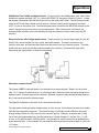
The second approach can be termed the "Water Analysis" approach. Obtain a complete water analysis of the
customer’s water. In addition to showing contaminants causing known problems, a complete analysis may reveal
problems that are not immediately apparent. The most common example is nitrate. Other examples include
silica, aluminum, and sulfate.
As with the two definitions, use BOTH approaches. Not only will you maximize the sales potential, you also will
be more likely to have a satisfied customer.
©2004 Culligan International Company
INTRODUCTION TO PROBLEM WATER 5
Chapter 2
Chapter 2
Problems and Causes
Review the following quick reference guide and determine which problem matches the problem defined by you
and/or your potential customer. Note the potential cause(s) and then refer to the Chapter 3, Causes, and
Chapter 4, Testing. NOTE: For contaminants not listed below but listed on the U.S. EPA drinking water standard
list, look for the particular contaminant in Chapter 3.
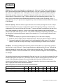
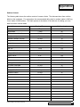
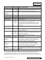
PROBLEM
Looks Bad
Turbidity
White
Brown
Black
POTENTIAL CAUSE
Suspended Solids
Dissolved gasses
Microorganisms
Aluminum
Iron (colloidal)
Metallic sulfides
Manganese
Microorganisms
Color
Yellow
Black
Blue
Bubbles
Smells Bad
Chlorine
Rotten egg
Petroleum/gasoline
Sewage
Tastes Bad
Salty
Bitter
Effervescent
Metallic
Soapy
©2004 Culligan International Company
Iron (colloidal)
Tannins
Metallic sulfides
Manganese
Copper
Detergent
Dissolved gases
Free chlorine
Chloramines
Hydrogen sulfide
Petroleum/gasoline
Microorganisms
Chloride
Sulfate
Bicarbonate
Copper
Iron
Zinc
Detergent
PROBLEMS AND CAUSES 7
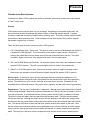
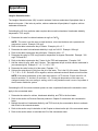
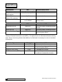
Problems and Causes
Causes Staining/Deposits
White
Red / Orange
Blue
Black
Slime
Causes Corrosion
Copper
Hardness
Silica
Total Dissolved Solids
Iron
Copper
Metallic sulfide
Manganese
Microorganisms
Glassware
Dissolved oxygen
Carbon dioxide
Chloride
Sulfate
Dissolved oxygen
Carbon dioxide
Chloride
Sulfate
Dishwasher detergent
Personal Appearance
Green hair
Mottled teeth
Dry skin
Copper
Fluoride
High pH (Alkalinity)
Iron
8 PROBLEMS AND CAUSES
©2004 Culligan International Company
Chapter 3
CHAPTER 3
Causes of Water Problems
Acidity and Alkalinity
Chemistry: Acidity is related to the amount of hydrogen ions (H+) in water. The higher the level of hydrogen
ions, the higher is the level of acidity.
Alkalinity is related to acidity since it is defined as the ability to neutralize acid. It consists of bicarbonate
(HCO3-1), carbonate (CO3-2), and hydroxide ions (OH-1).
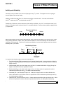
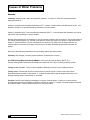
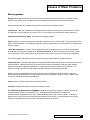
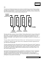
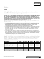
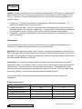
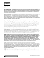
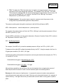
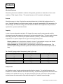
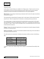
Traditionally, pH has been used to determine relative acidity or alkalinity. A pH of 7 is considered neutral, a pH
below 7 is considered acidic, and a pH above 7 is considered alkaline. However, these guidelines apply primarily to pure water.
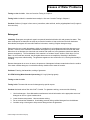
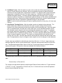
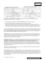
Theoretical pH Scale
Acidic
0
Neutral
Alkaline
7
14
Natural water supplies usually contain carbon dioxide, which combines with water to form carbonic acid. Unlike
strong acids (hydrochloric, sulfuric, nitric), this weak acid holds on to most of its hydrogen ions and acts like a
molecular acid storage tank. Therefore, pH, acidity, and alkalinity in natural water supplies should be looked at
differently than in pure water.
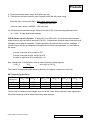
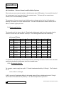
Real-World pH Scale
Free
Mineral
Acidity
0
4.3
8.3
Bicarbonate
Carbon
Dioxide
10
Carbonate,
Hydroxide
7
14
Bicarbonate,
Carbonate
The figure shows the pH ranges for which the following exist:
1. Free Mineral Acidity (FMA) represents the level of strong (mineral) acids. It occurs when the pH level is
below 4.3. Water supplies this low usually are associated with acidic mine drainage, and are considered
highly corrosive.
2. Carbon dioxide (CO2) can exist in water up to a pH of 8.3. A carbon dioxide level of 2 gpg (34 mg/L) or
higher is considered corrosive, regardless of the pH.
3. Bicarbonate (HCO3-1) can exist in a pH range of 4.3 to 10. When the level is expressed in calcium
carbonate equivalents (as CaCO3), it is called bicarbonate alkalinity.
4. Carbonate (CO3-2) can exist above a pH of 8.3. At this pH or higher, there is no carbon dioxide in the
water, and therefore no acid. When the level is expressed in calcium carbonate equivalents (as CaCO3),
it is called carbonate alkalinity.
5. Hydroxide (OH-1) can exist above a pH of 10. Water supplies with pH this high may affect the skin. When
the level is expressed in calcium carbonate equivalents (as CaCO3), it is called hydroxide alkalinity.
©2004 Culligan International Company
CAUSES OF WATER PROBLEMS 9
Causes of Water Problems
Problems:
Metal corrosion (low pH, high carbon dioxide)
Taste, effervescent (high bicarbonate)
White scale (high pH, high alkalinity)
Dry skin (high pH)
U.S. EPA drinking water standards (secondary):
pH : 6.5-8.5
Free Mineral Acidity: No standard, but FMA exists only below a pH of 4.3.
Hydroxide: No standard, but hydroxide exists only above a pH of 10
Testing on-site: Since carbon dioxide may escape from or dissolve into the water, on-site testing of
pH and carbon dioxide is recommended.
Testing in lab: Included in standard water analysis, depending on pH.
Products:
Neutralizer with Cullneu® media (low pH, high carbon dioxide)
Soda ash chemical feed (low pH, high carbon dioxide)
Dealkalizer (high alkalinity, high pH, but not over 8.3)
Acid chemical feed (high pH)
Weak-acid cation (carboxylic) resin
10 CAUSES OF WATER PROBLEMS
©2004 Culligan International Company
Causes of Water Problems
Aluminum
Chemistry: Although dissolved aluminum in water is often considered a cation (Al+3), its actual form depends on
the pH of the water:
Al+3 + H2O = Al(OH)+2 + H+
cation, very low pH
Al(OH)+2 + H2O = Al(OH)2+1 + H+
cation, low pH
Al(OH)+1 + H2O = Al(OH)3 + H+
solid, pH 6.2 – 6.5
Al(OH)3 + H2O = Al(OH)4-1 + H+
anion, neutral pH
Al(OH)4-1 + H2O = Al(OH)5-2 + H+
anion, high pH
Al(OH)5-2 + H2O = Al(OH)6-3 + H+
anion, very high pH
The above chemical equations indicate aluminum in water exists as a cation when the pH is below 6.2, as a solid
(aluminum hydroxide) when the pH is 6.2-6.5, and as an anion when the pH is above 6.5. However, there are no
sharp cutoffs regarding pH, since a typical water supply with a pH of 7.2 could contain both aluminum hydroxide
and anionic aluminum.
Water supplies with an extreme (especially low) pH level may contain a substantial amount of dissolved
aluminum. If the pH of the water is changed toward a pH of 6.5, some of the aluminum will precipitate and the
water will turn cloudy. In some applications, there is enough precipitated aluminum to foul water conditioners.
Municipal surface water supplies may have dissolved aluminum due to alum (potassium aluminum sulfate) being
fed at the water treatment plant to coagulate and settle fine particles.
Reverse osmosis membranes may become fouled by aluminum because of the pH change that occurs as the
water goes through the membrane. Because carbon dioxide, a dissolved gas, goes through the membrane but
bicarbonate does not, the pH of the product water typically is lower than the pH of the feed water. This decrease
in pH can cause some of the dissolved aluminum to precipitate inside the membrane.
Problems: Turbidity, membrane fouling
U.S. EPA Drinking Water Standard (secondary): 0.05 mg/L (0.2 mg/L if clay material is present)
Testing on site: Available
Testing in lab: Included in standard water analysis.
Products: Acid or soda ash feed to adjust pH to 6.5, followed by filtration.
©2004 Culligan International Company
CAUSES OF WATER PROBLEMS 11
Causes of Water Problems
Arsenic
Chemistry: Arsenic exists in water in two possible valences, +3 and/or +5. Both are considered poisons,
especially arsenic III.
Arsenic III (arsenite) acts somewhat like aluminum (Al+3), in that it is soluble both at low and high pH levels. Like
aluminum, arsenic III is not well reduced by softening or reverse osmosis.
Arsenic V (arsenate, AsO4-3) acts somewhat like phosphate (PO4-3). It can precipitate with hardness, and can be
reduced by anion exchange or reverse osmosis.
Because water treatment by ion exchange or reverse osmosis is effective only for arsenic V, the normal treatment
is to add an oxidizing agent (e.g., chlorine) to the water to oxidize any arsenic III to arsenic V, and then treat the
arsenic V. Because arsenic V can be converted back to arsenic III by metals such as copper and iron, the
oxidizing agent must remain in the water until just prior to the water treatment equipment that will treat the
arsenic.
New iron or alumina based adsorbants can successfully reduce both AsIII and AsV
Problems: Skin damage, circulatory system problems, increased risk of cancer.
U.S. EPA Drinking Water Standard (PRIMARY): 0.050 mg/L (50 parts per billion) NOTE: The
Primary Drinking Water Standard is scheduled to be reduced to 0.010 mg/L (10 parts per billion) in 2006.
Testing on site: Available. Test kit must be capable of detecting levels as low as 10 parts per billion.
Testing in lab: The water lab can test for total arsenic by special request. However, the report will not
discriminate between arsenic III and arsenic V. Contact the water lab for special sampling instructions if an
analysis showing arsenic III and arsenic V is needed.
Products: Chlorine feed followed by dealkalizer or reverse osmosis system. A variety of reverse osmosis
drinking water systems are third-party certified for reduction of arsenic V. Culligan is evaluating absorbant media
on a feild test basis. Contact Technical Services for more information.
12 CAUSES OF WATER PROBLEMS
©2004 Culligan International Company
Causes of Water Problems
Asbestos
Chemistry: Asbestos is a naturally occurring fibrous mineral. It is inert and insoluble. The most likely
occurrences in water would be surface supplies downstream of discharge from manufacturing processes using
asbestos (e.g., asbestos cement plants).
Problems: Lung disease, cancer
U.S. EPA Drinking Water Standard (PRIMARY): 7 MFL (million fibers per liter)
Testing on site: Not available
Testing in lab: Not available. Contact a local laboratory capable of testing for asbestos.
Products: Particulate filtration (whole house), with coagulation as needed. A variety of reverse osmosis and
cartridge filter systems are third-party certified for asbestos reduction.
Barium
Chemistry: Barium in water is an ion (Ba+2) with chemical characteristics similar to the hardness ions calcium and
magnesium. As such, it can be reduced by ion-exchange softening or reverse osmosis.
Unlike calcium, barium is more likely to precipitate as barium sulfate, which can cause fouling
problems for
reverse osmosis membranes and, in rare cases, softening resin. If the barium level is known, the sulfate level
should also be known to determine if fouling is a potential problem.
Problems: Scale. Higher levels of barium can cause problems with high blood pressure.
U.S. EPA Drinking Water Standard (PRIMARY): 2 mg/L
Testing on site: Not available
Testing in lab: Included in standard water analysis
Products: A variety of softeners and reverse osmosis drinking water systems are third-party certified for
reduction of barium.
©2004 Culligan International Company
CAUSES OF WATER PROBLEMS 13
Causes of Water Problems
Cadmium
Chemistry: Cadmium in water is a cation (Cd+2) with chemical characteristics similar to zinc. It can be reduced
by ion exchange softening or reverse osmosis.
Problems: Kidney damage
U.S. EPA Drinking Water Standard (PRIMARY): 0.005 mg/L (5 parts per billion)
Testing on site: Not available
Testing in lab: The water lab can test for cadmium by special request.
Products: Softener or reverse osmosis system. A variety of reverse osmosis drinking water products are thirdparty certified for cadmium reduction.
Chloride
Chemistry: Chloride in water is an anion (Cl-1) that is very soluble. It is most commonly associated with sodium,
as in table salt, sodium chloride (NaCl). Common sources of chloride include seawater intrusion, road salt, and
water softener discharge.
Problems: Salty taste. Hardness minerals diminish the taste, so it is enhanced when the water is softened.
Corrosion
U.S. EPA Drinking Water Standard (secondary): 250 mg/L
Testing on site: Available
Testing in lab: Included in standard water analysis
Products: Reverse osmosis. A variety of reverse osmosis drinking water products are third-party certified for
TDS/sodium chloride reduction. Polyphosphate chemical feed, where corrosion is a problem.
14 CAUSES OF WATER PROBLEMS
©2004 Culligan International Company
Causes of Water Problems
Chlorine
Chemistry: Chlorine and its related compounds do not occur in natural water supplies. Rather, chlorine is fed
into a water supply to control microorganisms or to oxidize contaminants like iron. Municipal treatment usually
involves gas chlorination, while private supplies are treated by feeding a bleach solution.
Free Chlorine. When chlorine gas is fed into water, it forms a solution of hypochlorous acid (HOCl). Bleach is
made by introducing chlorine gas into a dilute solution of caustic soda (NaOH), and the net result is sodium
hypochlorite. The hypochlorite ion also is called free chlorine, and the concentration is expressed in mg/L as
chlorine (Cl2).
Free chlorine kills microorganisms by passing through the cell wall and interfering with cell metabolism.
Hypochlorous acid passes through the cell wall more readily than hypochlorite ion, so sanitization is more
effective at a low pH, which favors the formation of hypochlorous acid. Some microorganisms such as
Crytosporidia and Giardia form cysts, which have a shell that prevents the passage of chlorine through the cell
wall. These microorganisms must be removed by fine filtration.
Chloramines. Some municipal water treatment plants also feed ammonia along with chlorine to form chloramines
(combined chlorine). Although chloramines are not as effective at killing microorganisms as is free chlorine, they
prevent biogrowth and are more stable in the municipal distribution system.
A typical procedure, called
breakpoint chlorination, is to feed chlorine in excess with ammonia so that the water leaving the municipal
treatment plant contains both free chlorine and chloramines. Often the free chlorine is gone by the time the water
reaches the home. In rare cases, the water supply already contains ammonia from fertilizer. Chlorination of such
water also will form chloramines.
Chlorinated hydrocarbons. One undesirable potential product of chlorine addition is chlorinated hydrocarbons
like trihalomethanes (THM’s), that are known to cause cancer. Chlorinated hydrocarbons may form when free
chlorine reacts with dissolved organic matter. The level of chlorinated hydrocarbons can be reduced by removing
the organic material prior to chlorination, or by using chloramines to reduce the need for high levels of free
chlorine. See section on Volatile Organic Chemicals.
Problems: Taste, odor, metal corrosion, harmful to fish
U.S. EPA Drinking Water Standard (PRIMARY): 4 mg/L (Maximum Recommended Disinfectant Level)
Testing on site: Because chlorine and chloramine levels can change after sampling, their levels should be tested
on site.
Testing in lab: Available, but not recommended.
Products: Cullar® activated carbon filter or carbon filter cartridge.
©2004 Culligan International Company
CAUSES OF WATER PROBLEMS 15
Causes of Water Problems
Chromium
Chemistry: Chromium can exist in water in two forms, Cr III (chromic ion, Cr+3) and Cr VI (chromate ion, CrO4-2,
or dichromate ion, Cr2O7-2). Cr III can form a variety of complex ions that are not removed by softening. Both Cr
III and Cr VI can be reduced by reverse osmosis or deionization.
Problems: damage to liver, kidney, circulatory and nerve tissues; allergic dermatitis
U.S. EPA Drinking Water Standard (PRIMARY): 0.1 mg/L
Testing on site: Available
Testing in lab: The water lab can test for chromium by special request.
Products: A variety of reverse osmosis drinking water products are third-party certified for chromium reduction.
Copper
Chemistry: Copper in water is a positive ion (Cu+2). Unlike many other contaminants, copper usually does not
come from the water source. Rather, the copper is a result of corrosion of copper piping. For this reason, the
U.S. EPA specifies corrosion prevention as the treatment for copper.
Copper corrosion commonly is associated with water that has a low pH level. However, a more important
consideration is the level of carbon dioxide (carbonic acid) in the water. Refer to the section, Acidity and
Alkalinity, in this chapter. Acid itself will not corrode copper metal, but it will remove the protective brown copper
oxide (Cu2O) coating, exposing metallic copper to corrosive elements in the water. This reaction is similar to the
one that occurs when acid flux is used to prepare copper pipe for soldering. Another potential source of acid is
waste products from microorganisms.
The primary cause of copper corrosion is an oxidizing agent like oxygen or chlorine. The oxidizing agent reacts
with copper to produce cupric (Cu+2) ions, which color the water blue and produce blue-green stains. A carbon
filter can reduce chlorine, but there is no practical method to remove oxygen from a residential water supply. The
alternative is to apply a different protective coating by feeding a polyphosphate or polyphosphate/silicate
chemical.
Problems: Liver or kidney damage (primary); blue-green stains, metallic taste, green hair (secondary), toxic to fish.
U.S. EPA Drinking Water Standard (PRIMARY): 1.3 mg/L
U.S. EPA Drinking Water Standard (secondary): 1.0 mg/L
16 CAUSES OF WATER PROBLEMS
©2004 Culligan International Company
Causes of Water Problems
Testing on site: Available. Also see Corrosion Testing in Chapter 4.
Testing in lab: Included in a standard water analysis. Also see Corrosion Testing in Chapter 4.
Products: Softener (if copper is from source); neutralizer, soda ash feed, and/or polyphosphate feed (if copper is
from corrosion).
Detergent
Chemistry: Detergents are synthetic organic compounds intended to dissolve oils and greases into water. They
were developed as an alternative to soaps to prevent the formation of soap curd when used with hard water.
Nevertheless, detergents will react with hardness in the water, resulting in higher detergent usage.
Detergents also may contain phosphates, which are intended to tie up hardness and make the detergent more
effective. However, such chemicals in dishwasher detergents may cause problems when used with soft water.
When there is no hardness, the chemicals can combine with metal ions in the glassware (metals are added to
glass to strengthen it). The first indication of this reaction is a "rainbow" sheen, similar to a thin layer of oil on
water. As the metals are removed, the silica glass becomes more susceptible to dissolving in the alkaline
detergent in a process called etching. The glassware appears to have a white film on it, but the glass actually is
corroding.
Because detergents do not occur in nature, the presence of detergents indicates contamination from the surface.
If the water contains detergent, a local health authority should test the water for bacteria.
Problems: Foaming, bad taste/odor, etching of glassware
U.S. EPA Drinking Water Standard (secondary): 0.5 mg/L (foaming agents)
Testing on site: Available
Testing in lab: The water lab can test for detergents by special request.
Products: Activated carbon filter with Cullar® G media. For glassware etching, recommend the following:
1. Use less detergent. Some dishwasher manufacturers include information on the appropriate amount of
detergent to use for a given hardness level.
2. Lower the water temperature. Heat accelerates etching.
3. Do not overload the dishwasher. Overloading prevents rinsing residual detergent from the dishware.
4. Consider using a rinse agent to help remove detergent from the glassware.
©2004 Culligan International Company
CAUSES OF WATER PROBLEMS 17
Causes of Water Problems
Dissolved gasses
Chemistry: Water can contain a variety of dissolved gasses that can cause problems, including carbon dioxide,
hydrogen sulfide, oxygen, and methane. Most occur naturally, but some systems have oxygen introduced due to
aeration, contact with air in a storage or pressure tank, or exposure of the water to air after the water has left the
tap.
Problems:
Carbon dioxide – (see Acidity and Alkalinity section in this chapter)
Hydrogen sulfide – (see Hydrogen Sulfide section in this chapter)
Oxygen – corrosion, unintended oxidation of iron
Methane – flammable when released from water and the air concentration reaches 5-15%
General – cloudy water, with the cloudiness clearing from the bottom up.
U.S. EPA Drinking Water Standard (PRIMARY): no standard, but water should be non-corrosive and not
produce objectionable odors.
Testing on site: Because gasses can escape from a water sample in transit, on-site testing is recommended.
See sections covering carbon dioxide or hydrogen sulfide for testing these gasses.
Dissolved oxygen test kits are available, but usually not required. Municipal water supplies and most surface
water supplies contain oxygen. A pressure tank with an air/water interface (no bladder) will add oxygen to the
water. Aeration or atmospheric storage tank systems also will add oxygen to the water. If none of these apply,
then consider testing for dissolved oxygen.
See Chapter 4, Testing, for information on testing for methane on-site.
Testing in lab: Not available, although carbon dioxide is calculated and the result is shown in the DI Calculations
section of the water analysis report.
Products:
Dissolved oxygen. Although a reducing agent like sodium hydrosulfite could be used to remove dissolved
oxygen, the resulting water would not be potable. The recommended treatment is polyphosphate. When
combined with a small amount of hardness (0.5 –1 gpg), the polyphosphate can put a coating on copper piping to
prevent contact of oxygen with the metal.
Carbon dioxide. (see section on Acidity and Alkalinity in this chapter)
Methane. Aeration, forced-draft
18 CAUSES OF WATER PROBLEMS
©2004 Culligan International Company
Causes of Water Problems
Fluoride
Chemistry: Fluoride dissolved in water is an anion (F-1). It occurs naturally in many water supplies, and in some
regions at high levels. Many municipal water treatment plants feed fluoride compounds to prevent tooth decay.
The typical level of fluoride in such waters is 1 mg/L.
Problems: Bone disease (PRIMARY), brown spotting of teeth in children (secondary)
U.S. EPA Drinking Water Standard (PRIMARY): 4.0 mg/L
U.S. EPA Drinking Water Standard (secondary): 2.0 mg/L
Testing on site: Available
Testing in lab: Included in a standard water analysis.
Products: A variety of reverse osmosis drinking water products are third-party certified for fluoride reduction.
Hardness
Chemistry: Hardness consists of calcium ions (Ca+2) and magnesium ions (Mg+2). Because of their relatively
strong charge, +2, they act like strong "magnets" and attract negative ions like carbonate (CO3-2) and sulfate
(SO4-2) to form scale. Hardness ions also combine with soaps to form a curd.
Other ions in water also have a +2 charge: iron (Fe+2), manganese (Mn+2), copper (Cu+2), zinc (Zn+2), barium (Ba+2),
strontium (Sr+2), radium (Ra+2), and lead (Pb+2). Iron and manganese ions cause problems with staining, which is
a form of scale. Barium and strontium may form sulfate scales on reverse osmosis membranes. Because these
ions can cause similar problems, because they have the same charge as calcium and magnesium, and because
a softener also can remove them, these ions also could be considered forms of hardness.
The tendency of a water supply to precipitate hardness scale can be estimated by calculating its Langlier
Saturation Index (LSI). The LSI is a function of the levels of calcium, bicarbonate alkalinity, Total Dissolved
Solids, pH, and temperature. A positive index indicates calcium carbonate scale will precipitate, while a negative
index indicates that calcium carbonate scale will dissolve. The index was developed to determine the effect of
water supplies on concrete aqueducts, which will be "corroded" if the LSI is negative. Water with a negative LSI
also would dissolve calcium carbonate from concrete pools and tile grout. Note: A negative LSI does not mean
that the water is corrosive to metal pipe. See the appendices for information on calculating the LSI.
©2004 Culligan International Company
CAUSES OF WATER PROBLEMS 19
Causes of Water Problems
Problems: Scale, soap curd, reduced life of clothing and bedding.
U.S. EPA Drinking Water Standard: none
Testing on site: Available. See section on "Diluting" in Testing chapter.
Testing in lab: Included in a standard water analysis.
Products: Softener.
Hydrogen Sulfide
Chemistry: Hydrogen sulfide (H2S) is a gas dissolved in water, and can be recognized by its
characteristic
rotten egg odor.
Although the odor alone is sufficient to identify the presence of hydrogen sulfide, the odor level should not be
used to determine the amount. Hydrogen sulfide can separate into hydrogen ions and bisulfide ions:
H2S = H+ + HS-1
Bisulfide ions remain dissolved in water and do not produce an odor. The higher the pH level, the more bisulfide
ions, and the lower the odor. Also, the higher the water temperature, the more hydrogen sulfide gas will escape,
so the odor will be more noticeable in warmer water.
There are three potential sources for hydrogen sulfide:
1. Decay of underground organic deposits. This source provides a relatively constant level of hydrogen
sulfide, although there can be variations due to changes in temperature or atmospheric pressure.
2. Sulfate Reducing Bacteria (SRB’s). These are a type of bacteria that ingest sulfate (SO4-2) and convert it
to hydrogen sulfide. This conversion takes time, so the level of hydrogen sulfide will increase as the
water sits in the pipes. The odor will be worse at first draw, then decrease as the water is used. Even if
the odor is stronger in the hot water, it should also be present in the cold water if it is due to SRB’s.
3. Water heater. Most water heaters contain an anode rod made from magnesium (Mg) or aluminum (Al).
Any corrosive substances in the water will react with the anode rod instead of the steel heater tank, so
the anode rod protects the tank from corrosion. One substance that can react with the anode rod is
sulfate (SO4-2):
4Mg + SO4-2 + 10H+ = 4Mg+2 + H2S + 4H2O
8Al + 3SO4-2 + 30H+ = 8Al+3 + 3H2S + 12H2O
20 CAUSES OF WATER PROBLEMS
©2004 Culligan International Company
Causes of Water Problems
Sulfate ions are converted to hydrogen sulfide. This conversion takes time, so the level of hydrogen sulfide will
increase as the water sits in the water heater. The odor will be worse at first draw, then decrease as the water is
used. Unlike hydrogen sulfide due to SRB’s, there should not be an odor in the cold water.
Hydrogen sulfide can combine with iron or copper ions to form metallic sulfides (FeS and/or CuS). In addition to
causing black stains, metallic sulfides tend to deposit on the inside of the plumbing. During periods of high flow,
some of the deposits may come off and go to service. Black particles to service may persist for some time even
after the hydrogen sulfide is removed.
Removal of hydrogen sulfide commonly involves oxidation to sulfate ions (SO4-2). In some applications, the
reaction produces elemental sulfur, a fine, sticky, milky-yellow solid. This material can plug pipes, control valves,
and media beds.
Problems: Rotten-egg odor, black stains (metallic sulfides). At high concentrations, hydrogen sulfide can be
poisonous and flammable.
U.S. EPA Drinking Water Standard (secondary): none, but water should not have an odor.
Testing on site: Recommended. Use a test kit that develops a blue color proportional to the amount of hydrogen
sulfide present. The use of a test kit that uses effervescing tablets (e.g., Alka-Seltzer® tablets) is not
recommended, due to field reports of inaccurate results. Also see sections on "Diluting" and "Solids Testing" in
Chapter 4.
Testing in lab: The water lab can test for hydrogen sulfide by special request, but a special sample bottle is
required. Contact the lab at Northbrook for details.
Products: Oxidizing filter (Cullsorb® filter, Super S® filter, Iron-Cleer™ filter) or Cul-Cleer™ system with either
chlorine or hydrogen peroxide chemical feed. Note: Only a chlorination system will correct a hydrogen sulfide
problem due to sulfate reducing bacteria.
©2004 Culligan International Company
CAUSES OF WATER PROBLEMS 21
Causes of Water Problems
Iron
Chemistry: Iron is the most common problem encountered in problem water applications. The problem is made
more difficult because iron can exist in a variety of forms, each of which may require a different type of water
treatment
Ionic iron consists of two types. Ferrous iron (Fe+2) is the most common type of iron encountered in private well
supplies. It also is known as clear water iron or soluble iron, since it has both characteristics. Ferric iron (Fe+3) is
uncommon in most water supplies. It is soluble only in water that has a low alkalinity. In such waters, the water
may have a yellow (not rust) color. Ferrous iron can be oxidized to ferric iron by oxidizing agents such as oxygen
and chlorine. Because municipal water supplies usually contain at least one of these oxidizing agents, they are
not expected to contain ionic iron.
Particulate iron (rust, Fe(OH)3 or Fe2O3.3H2O) is ferric iron that has precipitated with alkalinity to form a familiar
orange-brown stain or scale. There are two basic types of particulate iron, colloidal and filterable. The technical
definition of a colloidal particle is one that is so small (0.1 to 0.0001 micron) that molecular collisions are enough
to keep it in suspension. For water treatment purposes, a practical definition of a colloidal iron particle is one that
is smaller than the filter applied to remove it. From this definition, a filterable iron particle is large enough to be
removed by the filter applied to remove it.
Note: A third type of particulate iron is metallic iron. It comes from deteriorating iron pipe. The black particles of
metallic iron are unique in that they are attracted to a magnet.
A third class of iron is bound iron, and this class also consists of two types, organic-bound and polyphosphatebound. Organic-bound iron is a combination of iron and a dissolved organic material such as tannin.
Polyphosphate-bound iron is a combination of iron and polyphosphate fed by a municipal treatment plant.
Neither type of bound iron is removed by ion exchange or iron filters.
Iron bacteria commonly are included in a discussion of iron types. However, treatment for iron bacteria is the
same as for many other microorganisms, and iron bacteria should be considered a type of microorganism, not a
type of iron.
Problems: Reddish-brown stains, turns beverages black, metallic taste, fouls ion exchange resins
U.S. EPA Drinking Water Standard (secondary): 0.3 mg/L
Testing on site: Testing on site is the only way to determine the type(s) of iron present in the water. See the next
chapter, Testing.
Testing in lab: Included in standard analysis. However, the value represents total iron and does not indicate the
type(s) present on site.
Products: Ionic iron – softener, iron filter, Cul-Cleer® system with chlorine feed
Particulate iron – depth filter, cartridge filter, Cul-Cleer system with alum feed.
Bound iron – Cullar® activated carbon, macroporous anion resin (organic-bound), macroporous anion resin, hot
water cartridge filter (polyphosphate-bound)
22 CAUSES OF WATER PROBLEMS
©2004 Culligan International Company
Causes of Water Problems
Lead
Chemistry: Lead dissolved in water is a cation (Pb+2). Although it is occasionally present in a natural water
supply, the primary cause of lead in water is corrosion of lead piping or lead solder. For this reason, the U.S. EPA
specifies corrosion prevention as the treatment for lead. Buildings constructed after 1986 are unlikely to have
lead pipe or solder, which were banned by the U.S. EPA.
Problems: Infants and children: Delays in physical or mental development. Adults: Kidney problems; high blood
pressure
U.S. EPA Drinking Water Standard (PRIMARY): 0.015 mg/L (15 parts per billion) – action level
Testing on site: Available.
Testing in lab: The water lab can test for lead by special request.
Products: A variety of reverse osmosis drinking water products are third-party certified for lead reduction. A
softener can reduce lead levels, but not if the lead is due to corrosion after the softener. A neutralizer, soda ash
feed, and/or polyphosphate feed would be used if the lead level is due to corrosion.
Manganese
Chemistry: Manganese exists in water as a cation, Mn+2. It can be oxidized to Mn IV (manganese dioxide, MnO2)
by a variety of oxidizing agents, but the reactions usually are slow unless the pH is above 9. The exception is
permanganate, where the reaction is catalyzed by manganese dioxide:
Mn+2 + MnO4-1 = 2 MnO2
Some literature indicates soluble manganese can be oxidized by manganese dioxide to form manganic (Mn+3) ions:
Mn+2 + MnO2 + 4 H+ = 2 Mn+3 + 2 H2O
However, the manganic ion is not stable in water. Any manganic ion in water will "auto-oxidize" and convert to
soluble manganese and manganese dioxide. Although manganese dioxide can remove soluble manganese by
adsorption, this removal typically lasts only about six months.
©2004 Culligan International Company
CAUSES OF WATER PROBLEMS 23
Causes of Water Problems
Problems: Chocolate-brown to black stains, plugging of pipes with manganese dioxide, black particles to service.
U.S. EPA Drinking Water Standard (secondary): 0.05 mg/L (50 parts per billion)
Testing on site: Available. Also see Solids Testing section in Chapter 4.
Testing in lab: Included in standard analysis.
Products: Softener. Where softening is not practical, the alternative is a continuous-feed (potassium
permanganate) Cullsorb® filter.
Mercury
Chemistry: Mercury exists in water as a cation, Hg+2. However, mercury commonly combines with other
substances in the water to produce non-ionized or anionic compounds. Mercury also can be bound to organic
materials.
Problems: Kidney damage.
U.S. EPA Drinking Water Standard (PRIMARY): 0.002 mg/L (2 parts per billion)
Testing on site: Not available.
Testing in lab: The water lab can test for mercury by special request.
Products: A variety of reverse osmosis drinking water products are third-party certified for mercury reduction.
Because mercury can combine with a variety of substances, ion-exchange is not recommended for removal.
24 CAUSES OF WATER PROBLEMS
©2004 Culligan International Company
Causes of Water Problems
Microorganisms
Biology: Microorganisms are small forms of animal or plant life that exist in water or air. Examples include
bacteria, cysts, molds, fungi, and algae. Most microorganisms are harmless, and some are beneficial.
Some microorganisms are considered nuisances, but not harmful. Examples include:
Iron Bacteria. This type of bacteria forms stringy masses in toilet tanks and can plug faucet aerators. NOTE:
Iron bacteria is a form of bacteria, not a form of iron. Do not confuse iron bacteria with organic bound iron.
Sulfate Reducing Bacteria (SRB). (see section on Hydrogen Sulfide).
Algae. Algae are a variety of microscopic plants that commonly occur in surface water. They cause green, bluegreen, or brown deposits. The problem is especially evident in clear tubing or clear filter bowls, since alga growth
requires sunlight.
"Pink" Microorganisms. A variety of microorganisms can cause a bright pink stain, usually in toilet bowls or
showerheads. A common microorganism is Serratia marcescens, an airborne bacterium found in soil. When
new construction or other activity stirs up dust, the bacteria can travel to a moist environment like a bathroom.
The microorganisms of greatest concern are those that cause health problems. Examples include:
Coliform bacteria. Municipal water plants and local health departments monitor water for total coliform and fecal
coliform bacteria. Although a positive test for total coliforms does not necessarily mean the water contains
disease-causing microorganisms (pathogens), it requires that the water be tested for fecal coliforms. The
presence of fecal coliforms or E. coli indicates the water has been contaminated by sewage.
Cysts. Certain microorganisms form an outer shell for protection against harsh environments. When the
environment becomes favorable, the shell dissolves and the microorganism can grow. Two examples of cystformers are Giardia lamblia and Cryptospridium.
Viruses (enteric). Enteric viruses cause intestinal illnesses.
Problems: Gastrointestinal illness, sometimes resulting in death.
U.S. EPA Drinking Water Standard (PRIMARY): Rather than specifying a maximum contaminant level, the
standard refers to Treatment Techniques (TT’s). Treatment involves disinfection and filtration to
remove/inactivate Cryptosporidum by 99%, Giardia lamblia by 99.9%, and viruses by 99.99%. If there is a
positive test for Total Coliform, the water should be tested for fecal coliform. A second positive test for Total
Coliform, or a positive test for fecal coliform, indicates disinfection is required.
©2004 Culligan International Company
CAUSES OF WATER PROBLEMS 25
Causes of Water Problems
Testing on site: Field test kits are available for a variety of nuisance organisms such as iron bacteria and sulfate
reducing bacteria. Coliform bacteria tests usually are performed by local laboratories, such as a county health
service.
Testing in lab: Not available.
Products: The primary treatment for most microorganisms is chlorination. For private wells, the well should be
shock chlorinated and then re-tested. The well should be inspected for potential surface water intrusion due to
flooding or a bad well casing. If regrowth occurs too often for shock chlorination, continuous chlorination would
be required. A continuous chlorination system consists of a chlorine feeder and contact tank.
Chlorination will not destroy cysts, but cysts are relatively large particles that can be filtered. A variety of drinking
water systems are third-party certified for cyst reduction. Since cysts usually are found in surface water supplies
containing other microorganisms, disinfection is required before or after the cyst filtration system.
Ultraviolet systems also can be used to control microorganisms. Since there is no disinfectant residual after the
UV treatment, the system requires proper pretreatment and monitoring to ensure an adequate UV dosage when
the water is in the UV chamber.
Nitrate/Nitrite
Chemistry: Nitrate (NO3-1) and nitrite (NO2-1) are both anions. Nitrate is very soluble in water, so there are no
mineral deposits in the United States containing nitrate. The most common source of nitrate is fertilizer, although
nitrate also is associated with sewage. If nitrate or nitrite is detected at any level in the water, the water should be
tested for coliform bacteria (see section on Microorganisms).
Nitrite is the reduced form of nitrate. When exposed to air, it oxidizes easily to nitrate.
Problems: When ingested by infants or certain livestock, nitrate is converted to nitrite in the digestive system.
Nitrite can reduce the ability of blood to carry oxygen. An infant will turn blue and have shortness of breath ("Blue
Baby Syndrome"). These symptoms may result in death.
U.S. EPA Drinking Water Standard (PRIMARY): 10 mg/L nitrate as nitrogen (N); 1.0 mg/L nitrite as nitrogen (N).
NOTE: Certain states may have drinking water standards expressed as nitrate and nitrite rather than as nitrogen.
Comparable standards would be 45 mg/L nitrate as NO3, and 3.3 mg/L nitrite as NO2.
Testing on site: Available. Because it may convert to nitrate after sampling, nitrite testing should be done on
site. Since the nitrate comes from surface water, the concentration is likely to change over time due to variations
in fertilizer application and rainfall.
Testing in lab: Included in standard analysis.
26 CAUSES OF WATER PROBLEMS
©2004 Culligan International Company
Causes of Water Problems
Products: A variety of reverse osmosis drinking water products are third-party certified for nitrate and nitrite
reduction. For whole-house nitrate/nitrite reduction, reverse osmosis or nitrate-specific resin units are
alternatives. Whichever system is used, the nitrate levels of the untreated and treated water must be monitored
regularly.
Petroleum
Chemistry: Petroleum is a general term for oils, gasoline, greases, and similar hydrocarbons. Crude oil is
produced from the decay of organic materials deposited in seawater, so it often is associated with water that has
a high TDS level. Refined oil and gasoline in water is a result of contamination from industrial discharge, spills,
and storage tank leakage.
Refined petroleum products often contain additives such as MTBE and other volatile organic chemicals (VOC’s).
See section on Volatile Organic Chemicals.
Problems: Oily taste or odor. If the concentration is high enough, petroleum products will form a film on top of the
water surface. Petroleum can foul water treatment media.
U.S. EPA Drinking Water Standard: none
Testing on site: A rough test for petroleum can be performed using a camphor stick, which should be available at
a local pharmacy. Using a knife, place a few thin shavings of camphor on the surface of the water. If the water
has an oily film on the surface, the shavings will remain stationary as the camphor dissolves into the oil. If there
is no oily film, the shavings will spin due to camphor fumes evaporating into the air.
Testing in lab: The water lab can test for elevated (mg/L or ppm) levels of petroleum by special request. For low
(µg/L or ppb) levels, contact the water lab for more information.
Products: Activated carbon filter with Cullar® G media. For portable exchange carbon filters, a top dressing of
diatomaceous earth will soak up some petroleum and extend the life of the carbon.
Note: Do not feed chlorine into water containing petroleum, which may react with the chlorine to form chlorinated
hydrocarbons.
©2004 Culligan International Company
CAUSES OF WATER PROBLEMS 27
Causes of Water Problems
Radionuclides
Chemistry: Atoms contain an internal structure, or nucleus, that contains protons and neutrons. For atoms of
some elements, radionuclides, the nucleus is not stable and it eventually breaks down. During this process, a
new element is formed, and one or more types of radiation are emitted:
Alpha radiation, consisting of helium nuclei (two protons and two neutrons)
Beta radiation, or electrons
Gamma radiation, consisting of high-energy photons (e.g., x-rays)
Although a variety of elements are considered radioactive, the three elements normally encountered in water
treatment are radium (Ra), radon (Rn), and uranium (U).
Radium in water exists as a cation (Ra+2). Other than radioactivity, it has properties similar to calcium and
magnesium.
Radon is an inert gas that does not form an ion in water nor react with other atoms or molecules.
Uranium chemistry is relatively complex. Under anaerobic (no oxygen, reducing) conditions, the predominant
form likely is U+4, which likely complexes with carbonate or hydroxide. Under aerobic (oxygen, oxidizing)
conditions the predominant form is the uranyl ion, UO2+2, which complexes at higher pH levels with carbonate to
form uranyl dicarbonate (UO2(CO3)2-2) and uranyl tricarbonate (UO2(CO3)3-4).
Problems: Increased risk of cancer.
U.S. EPA Drinking Water Standard (PRIMARY): Radium, 5 pCi/L (picocuries per liter); Uranium, 0.030 mg/L (30
parts per billion, as of December 8, 2003). NOTE - Additional primary standards for radioactive substances
include: Alpha particles, 15 pCi/L; Beta particles and photon emitters, 4 millirems/year. In order to treat the water,
the source of the alpha and/or beta radiation must be known.
Testing on site: Not available.
Testing in lab: The water lab does not test for radioactive substances. Contact a local laboratory capable of
such testing.
Products: Radium. A variety of softeners and reverse osmosis drinking water systems are third-party certified for
radium reduction.
Radon. Radon in water can be reduced by about 50% with a forced-draft aeration system. Although activated
carbon also can reduce the radon level, its use is not recommended due to radioactive emissions (gamma) from
the carbon.
Uranium. Aeration or chlorination to oxidize any U+4, followed by a chloride anion dealkalizer to remove uranyl
carbonate ions can reduce uranium. However, the pH of the water must be maintained above 7.5 at all locations.
If the water entering the dealkalizer has a pH below 8, it may contain enough carbon dioxide to lower the pH of
the treated water below 7.5, and allow some uranium to pass to service. This decrease in pH can be avoided by
feeding soda ash with the chlorine, regenerating the dealkalizer with caustic as well as salt, or by adding soda
ash to the dealkalizer brine tank. Regeneration frequency should be based on total anion loading.
28 CAUSES OF WATER PROBLEMS
©2004 Culligan International Company
Causes of Water Problems
Selenium
Chemistry: The chemical properties of selenium (Se) are similar to those of sulfur. It can exist as hydrogen
selenide (H2Se), elemental selenium (Se8), and selenate (SeO4-2). Unlike with sulfur, oxidation is not an
acceptable treatment method, since the selenate ion still would be considered a health hazard.
Problems: Hair or fingernail loss, numbness in fingers or toes, circulatory problems.
U.S. EPA Drinking Water Standard (PRIMARY): 0.05 mg/L (50 parts per billion)
Testing on site: Not available
Testing in lab: The water lab can test for selenium by special request.
Products: A variety of reverse osmosis drinking water systems are third-party certified for reduction of selenium.
Silica
Chemistry: Silicon (Si) is the second most common element in the earth’s crust. When combined with oxygen, it
forms a wide variety of silicates, including quartz and other minerals found in rocks. Water treatment is
concerned with two types of silicates, dissolved silica and insoluble silica.
Dissolved silica includes metasilicate ions (SiO3-2) and orthosilicate ions (SiO4-4).
Dissolved silica also is known as reactive silica, since these ions will react with test chemicals.
The solubility of reactive silica is dependent on temperature. The approximate solubility may be calculated as
follows:
Solubility = (2 x Temperature, oC) + 75
For example, assume a water temperature of 55oF, or 12.8oC. The solubility of silica would be
Solubility = (2 x 12.8) + 75 = 100.6 mg/L
If soluble silica is concentrated in this water (on the waste side of an RO element, or in a drop of water that is
evaporating), silica will precipitate when the concentration exceeds about 101 mg/L.
©2004 Culligan International Company
CAUSES OF WATER PROBLEMS 29
Causes of Water Problems
Insoluble silica refers to particles of sand, clay, or other minerals. Particulate matter is covered in the section,
"Suspended Solids".
Problems (reactive silica): Spotting, especially when the level exceeds 25 mg/L. Fouling of reverse osmosis
membranes.
U.S. EPA Drinking Water Standard: None
Testing on site: Available (reactive silica).
Testing in lab: Reactive silica is included in a standard water analysis.
Products: Reactive silica is rejected by reverse osmosis membranes, but may cause scale problems in the
waste water. In most cases, adjusting the recovery of the reverse osmosis system can prevent the silica scale.
Although reactive silica is anionic, only strong-base anion resin will remove it, and only when the resin is
regenerated with caustic (a deionizer).
Sodium
Chemistry: Sodium in water is a cation (Na+1). It is very soluble in water, and therefore is present in most water
supplies.
High levels of sodium often are associated with seawater, which contains sodium at a level of about 13,000 mg/L.
Near a seacoast, salt water may intrude into the water supply. A shallow sea once covered the central United
States; salt deposits remaining after the seas evaporated can increase the sodium level. Since petroleum
deposits also were formed in this sea, high sodium levels also are associated with oil wells.
Problems: Taste and spotting are covered in the section, Total Dissolved Solids.
Sodium in the Diet. Some individuals are on low-sodium diets due to congestive heart failure or hypertension.
Even if they are not on a restricted diet, some individuals have expressed concerns about increased sodium in
softened water. These concerns should be addressed, not dismissed, since one purpose of water treatment is to
increase the customer’s quality of life.
The first step in addressing concerns about the sodium level is to determine the sodium level in the untreated
water. This is best done via a water analysis. Use the "as element" value, not the "as CaCO3" value.
Next, determine the total hardness in the untreated water. A softener will add the same amount of sodium, in
grains per gallon as CaCO3, to the water. Multiply this value by 7.866 to convert it to mg/L as the element
sodium.
30 CAUSES OF WATER PROBLEMS
©2004 Culligan International Company
Causes of Water Problems
Finally, add the value for sodium in the raw water to the value for sodium added by the softener. The result is the
level of sodium in the softened water.
Example: The sodium level from the water analysis is 61 mg/L as sodium. The Total Hardness is 6.3 gpg, so the
sodium added by softening would be (6.3 x 7.866 =) 50 mg/L as sodium. The total sodium in the softened water
would be (61 + 50 =) 111 mg/L.
Dietary intake generally is expressed in milligrams (mg). The U.S. EPA estimates the average daily intake is two
liters, so multiplying the sodium level by two results in the daily sodium intake from water. Using the example
above, the daily dietary intake would be (2 x 111 =) 222 mg.
Once the sodium intake due to water has been determined, it can be compared to sodium intake from other
sources. Many food containers now have nutrition information labels, including the milligrams of sodium per
serving. According to these labels, the recommended daily value for sodium intake is 2400 milligrams. Use the
information from the nutrition labels (using containers supplied by the customer, if possible) to determine daily
sodium intake. A table showing the sodium content of a variety of foods is shown in the appendices.
If the amount of sodium in the water is determined to be too high, it can be reduced by a reverse osmosis
drinking water system.
Plants. Grass, shrubs, trees, and flowers may be damaged if they are watered with water that is high in sodium.
As water evaporates from the soil, the sodium in the remaining water becomes more concentrated. A high
concentration of dissolved solids will prevent plant roots from taking in water. If there is adequate rainfall, the
dissolved solids will be diluted. If potted plants are watered thoroughly so that water flows from the bottom of the
pot, the dissolved solids will be rinsed from the soil.
Humidification. Humidifiers add moisture to the air through evaporation. As water evaporates, the dissolved
solids level increases in the remaining water. With hard water, this results in calcium carbonate scale coating the
reservoir and filter pad. Although soft water will not form scale as quickly as hard water, eventually the dissolved
solids concentration becomes high enough for sodium salts to form scale. Sodium scale can be blown out of the
humidifier and produce a sodium "dust". If this occurs, the reservoir should be drained and refilled with fresh
water. A better solution would be use reverse osmosis to treat the water for the humidifier.
U.S. EPA Drinking Water Standard: none. NOTE: Some states have established maximum levels for sodium.
Testing on site: Not available. A rough estimate of the sodium level can be obtained by subtracting the total
hardness level from the Total Dissolved Solids level. All values should be in mg/L as calcium carbonate. To
convert the value to mg/L as sodium, multiply by 0.46.
Testing in lab: Included in a standard water analysis.
Products: Reverse osmosis, deionizer.
©2004 Culligan International Company
CAUSES OF WATER PROBLEMS 31
Causes of Water Problems
Strontium
Chemistry: Strontium in water is an ion (Sr+2) with chemical characteristics similar to the hardness ions calcium
and magnesium. As such, it can be reduced by ion-exchange softening or reverse osmosis.
Unlike calcium, strontium is more likely to precipitate as strontium sulfate, which can cause fouling problems for
reverse osmosis membranes. If the strontium level is known, the sulfate level should also be known to determine
if fouling is a potential problem.
Problems: Fouling of reverse osmosis membranes.
U.S. EPA Drinking Water Standard: None
Testing on site: Not available.
Testing in lab: Included on a standard water analysis.
Products: Softener.
32 CAUSES OF WATER PROBLEMS
©2004 Culligan International Company
Causes of Water Problems
Sulfate
Chemistry: Sulfate in water is an anion (SO4-2). It is dissolved from deposits of gypsum (calcium sulfate), which
is known for its use in drywall. Sulfate also forms from the oxidation of hydrogen sulfide. The oxidation of
hydrogen sulfide in coal mines results in the formation of sulfuric acid, so the pH of water from coal mines
typically is very low.
Problems: Levels above the drinking water standard may cause a bitter taste. Higher levels also may cause a
laxative effect in humans and livestock (scours). As sulfate becomes more concentrated in reverse osmosis
waste water or a humidifier reservoir, it may precipitate with calcium, barium, or strontium to form an insoluble
scale.
U.S. EPA Drinking Water Standard (secondary): 250 mg/L
Testing on site: Available
Testing in lab: Included on a standard water analysis.
Products: A variety of reverse osmosis drinking water systems are third-party certified for reduction of sulfate.
Whole-house reduction of sulfate can be accomplished by a larger reverse osmosis system, or by a chloride
anion dealkalizer, which replaces sulfate with chloride.
Suspended Solids
Chemistry: The term, suspended solids, refers to materials in water that are solid rather than dissolved. The
most common suspended solid is rust, but others include sand, clay, and even microorganisms. Although the
exact composition of the solids usually is not important, knowing the density and particle size is.
Some types of suspended solids, like sand, are too dense to remain suspended in the water very long. These
dense solids also are difficult to backwash out of a depth filter, which eventually becomes plugged. If the
suspended solids settle from the water in less than a minute, a centrifugal separator should be used to remove
them. NOTE: A centrifugal separator will remove only those particles that settle rapidly.
There are two general classes for particle size, filterable and colloidal. Filterable solids are those that are larger
than the micron rating of the filter used to remove them. Colloidal solids are those that are smaller. Therefore,
the classification will depend on the filter chosen. A depth filter is rated to remove particles with a nominal
diameter of 10 microns (10µ), while some cartridge filters have a rating as fine as 0.35 micron.
In some rare cases, the concentration of suspended solids is important. If the concentration is too high, a depth
filter may become plugged before it has a chance to regenerate. For example, with a water usage of 400 gallons
a day and a 9" Filtr-Cleer depth filter, the suspended solids limit would be about 800 mg/L.
©2004 Culligan International Company
CAUSES OF WATER PROBLEMS 33
Causes of Water Problems
Problems: Cloudiness (turbidity); plugging; deposits in sinks and toilets; interference with disinfection, especially
ultraviolet systems.
U.S. EPA Drinking Water Standard: None
Testing on site: Not available. NOTE: Many surface water supplies appear to be clear, but they contain a
substantial amount of fine suspended solids that may foul a reverse osmosis element. The fouling potential can
be measured in the field using a Silt Density Index (SDI) test kit, Cat. No. 00-4483-20. This test is highly
recommended when applying commercial elements of 4" diameter.
Testing in lab: The water lab can test for suspended solids by special request. Specify a "depth filter analysis."
The report will show suspended solids larger than 10 microns ("suspended coarse"), suspended solids between
0.45 microns and 10 microns ("suspended fine"), and Total Suspended Solids, as well as turbidity before and
after 10 micron filtration.
Products: Centrifugal (cyclone) separator for dense suspended solids like sand. Depth filter. Particulate
cartridge filter. A variety of reverse osmosis drinking water systems and carbon block cartridge filters are thirdparty certified for reduction of cyst particles, but they will require pretreatment to remove other suspended solids.
Tannins
Chemistry: "Tannins" is a general term for dissolved organic material from the decay of plants. Examples of
these relatively large organic molecules include tannic acid, humic acid, and fulvic acid. The familiar yellowbrown color in tea is due to tannins.
When iron and tannins are present in a water supply, the tannins may bind with the iron to form organic-bound
iron (see section on Iron).
Problems: Yellow-brown color. At high levels, tannins may form an oily film on the water surface.
U.S. EPA Drinking Water Standard (secondary): None, but color standard is 15 color units.
Testing on site: Available.
Testing in lab: Included in a standard water analysis if the color level is higher than 5 color units.
Products: Activated carbon filter with Cullar® D media. Macroporous anion resin system. NOTE: The type of
tannins will depend on the type of decaying organic material, which will differ from region to region. CS-5 resin is
known to work well in Florida, while Macro-T resin is recommended for northern states. A Cul-Cleer™ system
with alum coagulation, retention, and particulate filtration may be needed for large amounts of tannins.
Chlorination has not proven to be effective for tannin reduction due to the large amount of contact time (hours)
required.
34 CAUSES OF WATER PROBLEMS
©2004 Culligan International Company
Causes of Water Problems
Total Dissolved Solids
Chemistry: Total Dissolved Solids (TDS) most commonly refers to the level of dissolved ions in water. Although
pure water does not conduct electricity very well, ions dissolved in the water do conduct electricity. The more
ions are dissolved in water, the higher the conductivity. The conductivity is measured by a meter to give a
reading in microSiemens/cm (µS/cm) or, on older meters, micromhos/cm (µmhos/cm). Using an internal
multiplier of about 0.55, TDS meters give readings in mg/L or ppm.
Some ions conduct electricity better than others. For example, sodium ions will conduct electricity better than an
equivalent level of calcium ions. This is why softened water typically will have a higher conductivity than the hard
water. Silica ions do not conduct electricity very well at all. Therefore, TDS by conductivity is an estimate of the
actual level of dissolved ions.
Another method to determine TDS is to measure the levels of all the ions in the water, then add the values. This
is the most accurate method for determining the TDS level of dissolved ions, but it requires a complete water
analysis.
Although less common, Total Dissolved Solids also can refer to the level of all dissolved substances in water,
including non-ionic material (usually dissolved organics). This TDS is measured by filtering a water sample to
remove suspended solids, evaporating the water, and weighing the remaining material.
Problems: Bad taste. The type of anion present is the primary cause of the taste:
Chloride – salty
Sulfate – bitter
Bicarbonate – astringent
High hardness tends to mask the taste, while low hardness tends to enhance it.
Scale and spots are caused by high TDS. Although softening will decrease the amount of scale in many cases,
spotting still would be a problem when the water evaporates. However, soft water spots are significantly easier to
remove than hard water spots.
High TDS also can accelerate corrosion.
U.S. EPA Drinking Water Standard (secondary): 500 mg/L
Testing on site: A variety of TDS meters are available.
Testing in lab: The conductivity, the estimated TDS by conductivity, total cations, and total anions values are
included in a standard water analysis.
Products: A variety of reverse osmosis drinking water systems are third-party certified for TDS reduction. Series
B reverse osmosis systems are available to reduce the TDS level in the water for the whole house.
©2004 Culligan International Company
CAUSES OF WATER PROBLEMS 35
Causes of Water Problems
Turbidity
Chemistry: Turbidity is a measurement of the cloudiness of the water. It is measured by shining a beam of light
through the water. A photocell, located at 90 degrees to the light beam, measures the amount of light reflected off
the particles suspended in the water. The result is compared to a standard and reported in Nephalometric
Turbidity Units (NTU). Because the reflectance of the particles is dependent on their shape and color, turbidity
cannot be directly related to the amount of suspended solids in the water. The turbidity value may be masked if
the particles are non-reflective (e.g., black).
Problems: Cloudiness. Interference with transmission of disinfecting UV light. May indicate the presence of
large amounts of microorganisms.
U.S. EPA Drinking Water Standard (PRIMARY): The standard is a Treatment Technique for water treatment
plants requiring that the turbidity never exceed 1 NTU, nor 0.3 NTU in 95% of daily samples any month. The
standard applies to systems using surface water or ground water under the direct influence of surface water.
Testing on site: Available, but expensive.
Testing in lab: Included in a standard water analysis. Turbidity values are reported for the sample as received
and after 10-micron filtration. The second value indicates the approximate turbidity after a depth filter. NOTE: If
the sample contains iron, the turbidity value may not be valid. The turbidity may be caused by iron that oxidized
while the sample was in transit.
Products: Depth filter, cartridge filter, or Cul-Cleer™ system with alum feed, retention, and filtration.
Volatile Organic Chemicals
Chemistry: The term Volatile Organic Chemicals (VOC’s) refers to a wide variety of organic chemicals.
Some of these chemicals are the result of disinfection processes like chlorination, and are referred to as
Disinfection Byproducts (DBP’s). Chlorine can react with organic molecules like methane or tannins to produce
dichloromethane, trichloroethane, and other suspected cancer-causing chemicals. Other chemicals, like Methyl
Tertiary Butyl Ether (MTBE) come from gasoline spills. Still others come from pesticide or herbicide leaching into
an aquifer (e.g., atrazine). For a list of the chemicals, refer to the U.S. EPA drinking water standards list in the
appendices.
Problems: Many of these chemicals are associated with cancer, kidney problems, and liver problems (refer to
the U.S. EPA drinking water standards list in the appendices).
U.S. EPA Drinking Water Standard (PRIMARY): (refer to the U.S. EPA drinking water standards list in the
appendices)
Testing on site: Not available.
36 CAUSES OF WATER PROBLEMS
©2004 Culligan International Company
Causes of Water Problems
Testing in lab: Not available. Contact a local laboratory capable of analyzing these substances.
Products: Activated carbon. A variety of carbon cartridge systems are third-party certified for reduction of
specific volatile organic chemicals. For whole-house treatment, the recommended carbon is Cullar® CC media, a
coconut-shell carbon. The minimum carbon volume should be one cubic foot for every gallon per minute of flow
rate. The carbon volume should be split equally between two tanks in series, and sampling valves should be
installed before, between, and after the tanks. A typical residential application will have two 12" portable
exchange carbon filters in series, each with 2.5 cubic feet of Cullar CC media. Arrangements should be made for
monitoring contaminant breakthrough. When the carbon in the first tank is exhausted, the second tank should
become the primary tank, and a fresh carbon tank should be placed in the second position. Note: The exhausted
carbon may have to be handled as hazardous waste.
Zinc
Chemistry: Zinc in water is a cation (Zn+2). It rarely occurs at significant levels in natural water. Rather, zinc in
water usually is due to corrosion of galvanized iron plumbing or brass fixtures.
Problems: Bitter taste.
U.S. EPA Drinking Water Standard (secondary): 5 mg/L
Testing on site: Available
Testing in lab: Included on a standard water analysis
Products: Softener (but not if zinc is due to corrosion). Neutralizer or soda ash feed if the carbon dioxide level is
high (see section on Acidity and Alkalinity). Polyphosphate feed. Also see Corrosion Testing in Chapter 4.
©2004 Culligan International Company
CAUSES OF WATER PROBLEMS 37
Chapter 4
Chapter 4
Testing
Laboratory Water Analysis
The water analysis laboratory at Northbrook offers a variety of analyses, the most common of which is a
"standard" analysis. An example of a standard analysis is shown on the following pages. Problems associated
with individual constituents are described in Chapter 3, so this section describes parameters associated with the
analysis.
Dimensions
The term "dimensions" refers to how the levels are reported.
The turbidity dimension is Nephalometric Turbidity Units (NTU). The unit is based on a set of standards of
specific cloudiness. Turbidity after filtration is measured after filtering the sample through a nominal 10-micron
filter.
The conductivity dimension is micromhos/centimeter (µmhos/cm), a measure of how well the water sample
conducts electricity. A higher conductivity indicates the level of dissolved ions in the water, so it is used to
calculate the estimated TDS by conductivity, which is reported in milligrams/liter (mg/L).
The color dimension is Color Units (CU), and is based on a set of standards of specific yellow colors. If the color
is higher than 5 CU, the sample is acidified and re-tested. A decrease in color indicates it was due to colloidal
iron. Color remaining after acidification likely is due to tannins or other dissolved organic material. Note: Colors
other than yellow (e.g., blue) will not be reported accurately.
The pH dimension is pH units.
All other values are reported in milligrams per liter (mg/L), micrograms per liter (µg/L), or grains per gallon (gpg).
One liter of pure water weighs one million milligrams, so 1 mg/L is the same as one part per million (ppm). One
liter of water weighs one billion micrograms, so 1 µg/L is the same as one part per billion (ppb). For conversion,
use the following table:
To convert from To
Multiply by
PPM
PPB
1000
PPB
PPM
0.001
GPG
PPM
17.1
GPG
PPB
17,100
PPM
GPG
0.058
PPB
GPG
0.000058
©2004 Culligan International Company
TESTING 39
Testing
Conversion Factors
Many of the values for cations (positive ions) and anions (negative ions) are reported both "as element" and "as
CaCO3".
The values reported as the element are used for comparison to standards. For example, if the chloride level as
element is over 250 mg/L, it exceeds the U.S. EPA secondary drinking water standard for chloride.
The values reported as calcium carbonate equivalents are used for ion exchange calculations. Ion exchange
involves the charge on the ion, not the weight. For example, a softener will replace one calcium ion (Ca+2, weight
40.1) or one magnesium ion (Mg+2, weight 24.3) with two sodium ions (Na+1, weight 23.0 each). To calculate
capacity, the “as element” values must be converted to equivalent weights, which consider both the element
weight and the ionic charge. By convention, the water treatment industry uses calcium carbonate (CaCO3)
equivalents.
The general calculations for the conversion factors are
Conversion factor, as element to as CaCO3 =
50
Ionic weight/charge
Conversion factor, as CaCO3 to as element =
Ionic weight/charge
50
For example, calcium has an ionic weight of 40.1 and a charge of 2. The conversion factor, as element to as
CaCO3, is (50/(40/2) = ) 2.5. To convert from as CaCO3 to as element, the conversion factor is ((40/2)/50 = ) 0.4.
Note that these values are reciprocals. The number 50 is the equivalent weight of calcium carbonate.
Calculating conversion factors requires knowledge of ionic weights and charges. The calculations become more
complicated when an ion can have more than one charge, like iron (Fe+2, Fe+3). A table of common conversion
factors is located in the appendices.
40 TESTING
©2004 Culligan International Company
Testing
Additional Information
The top of page 2 of the certificate of analysis shows those parameters that exceed the U.S. EPA Primary
(health-related) and Secondary (aesthetics-related) drinking water standards. This information serves to highlight
particular problems. However, the standards change regularly, and new standards may be in effect when you
review the analysis. To obtain the latest information, visit the EPA website,
http://www.epa.gov/safewater/mcl.html.
The middle of page 2 of the certificate of analysis shows typical concentration of certain ions in reverse osmosis
product water, based on the concentrations in the feed water. Higher feed pressure and pH, and lower feed TDS
and % recovery (lower ratio of product water to feed water) generally result in lower concentrations in the product
water.
The DI Calculations are used to determine capacity and quality from a deionizer system. Because of the work
involved in using these numbers for sizing, most applications now are sized by entering the analysis information
directly into the deionizer section of the CAAP® (Computer Aided Application Program) software.
Other Analyses
In addition to standard analyses, the water lab can test for a variety of water parameters. The most-requested
additional test is Total Organic Carbon (TOC). The TOC result represents all organic carbon in a water sample,
including tannins, petroleum, and microorganisms. Values over 3 mg/L are considered high enough to foul
standard anion resin.
In some applications, the unknown substance is a solid, rather than water. The most common examples are
hardness scale and rust. The water lab can test the solid material if enough is available. At least a teaspoon of
material is required. Also see the section on field testing of solids.
©2004 Culligan International Company
TESTING 41
Testing
Report 7/8/02 Page 1 of 2
CERTIFICATE OF ANALYSIS
ANALYSIS NUMBER:0201234
Culligan Water Conditioning
123 Main St.
Anytown,
USA 98765
Zip
98765
Account
56789
Control
Customer JAN ANNETTE
Customer Account
cc:
Salesperson CDF
SAMPLE
Analysis Type Standard A Analysis
Sampled:
6/20/02
Supply/Source:
PRIVATE WELL
Condition:
UNTREATED
Received:
6/25/02
Sampling
PRESSURE TANK Application: Household
ANALYSIS INFORMATION:
Turbidity(Method 180.1)
40.8 NTU
Turbidity after filtration
7.7
Conductivity(Method 610.0 MMHOS/CM
Est. TDS by Conductivity
399.9
Color(Method 2120C)
6.5
Color after Acidification
5.2
pH(Method 150.1)
6.7
Tannins
N.D.
Concentrations reported as mg/L (PPM) unless otherwise noted
CATIONS (Method 200.7)
ANIONS (Method 300.0)
As Element
As CaCO3
As Element
As CaCoO3
Calcium (Ca)
Magnesium (Mg)
Sodium (Na)
Potassium (K)
Strontium (Sr)
Barium (Ba)
Iron (Fe)
Manganese (Mn)
Copper (Cu)
Zinc (Zn)
65
162.5
Chloride (Cl)
1.7
2.4
30.6
126.1
Nitrate/Nitrite (N)
N.D.
N.D.
1.2
2.6
Sulfate (SO4)
239
248.6
2.1
2.7
Bicarbonate (HCO3) 37.9
31.0
0.1
0.1
Carbonate
N.M.
N.M.
0.04869
Fluoride (F)
0.2
0.50
3.56
Silica (SiO2)
33.9
0.23
1.661
6.49
Mg/L GPG
Mg/L GPG
Mg/L GPG
Cations
293.9 17.19 Anions
282.6 16.52 Hardness (CaCO3) 289
16.9
----------------------------------------------------------------------------------------------------------------------------------------Additional Tests
Aluminum by ICP
145.00ug/L
*NA = Not Analyzed NM = Not Measured ND = Not Detected
This report can only be reproduced in its entirety. The results reported here are representative of the sample as received in
the laboratory. Testing is in compliance with current NELAP requirements
State Laboratory Certifications: CA- 01133A; IL -000280; NY- 11756
Richard Cook
Manager Analytical Laboratory
42 TESTING
©2004 Culligan International Company
Testing
Analysis
0201234
Page 2 of 2
Consumer
JAN ANNETTE
----------------------------------------------------------------------------------------------------------------------------------------FEDERAL SAFE DRINKING WATER
All tested parameters exceeding the maximum contaminant levels (MCL) established by the
"Federal Safe Drinking Water Act".
Parameter
Found
MCL
PRIMARY
Turbidity
40.8 NTU
0.50 NTU
SECONDARY
Zinc (Zn)
6.49 mg/l
5.00 mg/l
Manganese (Mn)
0.23 mg/l
0.05 mg/l
Iron (Fe)
3.56 mg/l
0.30 mg/l
Copper (Cu)
1.66 mg/l
1.00 mg/l
Aluminum by ICP
0.14 mg/L
0.05 mg/L
* MCL for Turbidity varies as follows:
1. Municipal Direct Filtration
0.5 NTU
2. Municipal Sand Filtration
1.0
3. Unfiltered Water
5 NTU
----------------------------------------------------------------------------------------------------------------------------------------TYPICAL POST RO DRINKING WATER UNITS
(Concentrations reported as mg/L (PPM) as the element)
Calcium (Ca)
1.3
Iron (Fe)
0.2
Magnesium (Mg)
0.6
Manganese (Mn)
0.0
Sodium (Na)
0.0
Zinc (Zn)
0.1
Potassium (K)
0.0
Copper (Cu)
0.0
Chloride (Cl)
0.1
Nitrate/Nitrite
0.0
Sulfate (SO4)
2.4
Fluoride (F)
0.0
These values are typical of new modules on water with a pH of 7-9 at 70-74 F with 500-3000
salts operating with 40-70 PSI pressure across the module. Local conditions may yield different
results.
----------------------------------------------------------------------------------------------------------------------------------------DI CALCULATION
GPG
mg/l
Sodium
0.9%
Weak Base Fact X
14.7
251.3
Alkalinity
13.4%
Carbonic Acid
4.2
71.1
Chloride
0.9%
Cation Fact Y
17.2
294.0
Carbonic Acid
16.1%
Silica
1.6
28.15
Monovalent Ions
0.7%
Carbon Dioxide
1.0
16.6
Silica
10.0%
Strong Base Fact Z 19.8
339.4
----------------------------------------------------------------------------------------------------------------------------------------Analysis
Method
Date
Method
Date
120.1
06/28/02
150.1
06/28/02
180.1
06/27/02
200.7
06/29/02
2120C
06/27/02
300.0
06/27/02
----------------------------------------------------------------------------------------------------------------------------------------©2004 Culligan International Company
TESTING 43
Testing
Field Testing
In many applications, the best, or only, way to test for a specific parameter is on-site. This particularly
applies to parameters that many change while the sample is in transit. Examples include chlorine,
hydrogen sulfide, methane, carbon dioxide, and iron.
Diluting
Before starting a test, determine if the test procedure develops a color that is compared to color
standards on a label, chip, cube, or wheel, and the resulting value is in mg/L or gpg. If the developed
color is at or near the upper limit of the color standard, the actual concentration may be above the limit.
Dilute the sample with deionized water and re-test until the concentration value is in the middle of the
test range. Multiply the value by the dilution factor to determine the concentration of the substance in
the undiluted water. NOTE: Diluting the sample also may be helpful when using drop-count titration
method (e.g., hardness test) when you expect the concentration will be high. By diluting one part
sample with one part DI water, the number of drops required will be cut in half. Counting is simplified
and less chemical is required.
The dilution factor is the sum of the parts of deionized water added to one part of the sample water.
For example, if 3/4 cup (3 parts) of deionized water is added to 1/4 cup (1 part) of sample, the dilution
factor is four.
Chlorine
Two types of tests are available, free chlorine and total chlorine. Use the free chlorine test to
determine chlorine residual after a retention or contact tank. Use the total chlorine test to determine
the effectiveness of treatment for free chlorine and chloramine removal. To determine the chloramine
level, perform both tests and the following calculation:
Chloramines = Total Chlorine – Free Chlorine
Hydrogen Sulfide (see Hydrogen Sulfide section in Chapter 3)
Methane
For methane, use the "Flash Test".
1. Fill a plastic bottle with the water, leaving about one inch of air space above the water.
Cap the bottle tightly.
2. Shake the bottle vigorously or allow it to come to room temperature.
3. Light a match, remove the cap, and place the flame close to the bottle opening.
4. Observe the flame.
a. If there is a pop or a flare, the gas likely is methane.
b. If the flame goes out, the gas likely is carbon dioxide.
c. If the flame burns normally, the gas likely is air.
44 TESTING
©2004 Culligan International Company
Testing
Iron
The best way to determine the type(s) of iron present is in the field using a series of "demo" cartridges
you prepare at your dealership. Start with an empty Flavr-Gard™ cartridge, Cat. No. 00-9552-63 and
add media as indicated below. If you do not have used Flavr-Gard housings, ordering a complete filter,
Cat. No. 00-4450-63, will cost less than ordering a head and bowl.
1-MICRON
CARTRIDGE
CULLAR FILTER
SOFTENER
DEPTH FILTER
FILTERABLE
FERROUS
COLLOIDAL
ORGANIC BOUND
COLLOIDAL
(<1 MICRON)
COLLOIDAL
FERROUS
ORGANIC BOUND
COLLOIDAL
ORGANIC BOUND
COLLOIDAL
(<10 MICRON)
The demo depth filter contains 4" (10 cm) of Cullsan® U filter medium below 4" (10 cm) of Cullsan G-50
filter medium. A 10-micron cartridge filter could be used in place of the demo depth filter, but small air
bubbles in the cartridge will oxidize some of the ferrous iron, affecting the accuracy of the test. As
indicated in the diagram, a demo depth filter removes only filterable iron (particles of rust larger than 10
microns).
The demo softener contains 0.033 cubic feet of Cullex® resin. It will remove ferrous iron, but not bound
or colloidal iron. Because of the small volume of resin, exhausted resin should be replaced with new
resin rather than be regenerated.
The demo activated carbon filter is filled with 0.033 cubic feet (about 7/8 pound) of Cullar® D media, the
recommended activated carbon for organics removal. A carbon cartridge filter could be substituted, but
the carbon in these cartridges is intended primarily for chlorine removal, not organics removal. If you
use macroporous anion resin for organics removal, substitute this resin for the Cullar D media. This
filter removes organic bound iron.
Iron that passes through the first three filters is particulate iron smaller than 10 microns. According to
field reports, in many applications these small particles of rust are larger than 1 micron. Therefore, if
iron passes through the first three housings, add a fourth housing with a 1-micron cartridge to
determine if it will remove the remaining iron. If so, a Plymouth Products model DGD-2501 cartridge
with Big Blue housing would be recommended.
©2004 Culligan International Company
TESTING 45
Testing
The filter housings should be connected with flexible tubing and quick-disconnect fittings. Since the
system will be operated at line pressure, the demo depth filter inlet tubing should use a garden hose
connector for attachment to a laundry tub faucet or outside hose bib. The flow rate for testing should
be 0.25 – 0.5 gpm. Use the top of a household brine valve with a 0.45 gpm flow control for a
convenient method of controlling the flow.
To start, test the raw water for iron. Particulate iron may take some time to dissolve, so the color may
get deeper with time. Wait about 5 minutes for the color to stabilize. In the meantime, connect the
demo depth filter inlet to the raw water and the flow control to the outlet. Turn on the water, relieve air
from the filter housing, and allow the water to flow for five minutes. Take a sample after the filter and
test for iron. If iron is present, connect the softener after the depth filter and connect the flow control
after the softener. Test the water after the demo softener for hardness to verify that the softener is
working. If you get a hardness bleed through the softener, you also will get an iron bleed, and the test
will not be valid. Test the soft water for iron. If iron is present, continue testing with the carbon filter
and, if iron still is present, with the 1 micron cartridge filter.
Now compare the results of the iron tests to determine the type(s) of iron present. For example:
Raw:
After depth filter
After softener:
After Cullar filter:
After 1 micron filter
5.0 mg/L
4.5 mg/L (removed 0.5 mg/L filterable iron)
2.5 mg/L (removed 2.0 mg/L ferrous iron)
1.0 mg/L (removed 1.5 mg/L organic bound iron)
0.2 mg/L (removed 0.8 mg/L filterable iron)
The 0.2 mg/L of iron that passed through all three units is likely to be colloidal, which will require
coagulation for removal. It could also be polyphosphate bound iron if the water is a municipal supply
treated with polyphosphate (contact the water treatment plant operator). Please note that the iron level
is below the U.S. EPA secondary drinking water standard of 0.3 mg/L, so further treatment may not be
needed.
Corrosion Testing
If we suspect that copper or iron in water is due to corrosion of plumbing, we want to sample the water
that is resting in the pipes. The standard procedure of letting the water flow before taking a sample will
flush the corrosion products down the drain, so the testing procedure for corrosion requires a modified
procedure:
1. Turn on the water and allow only a cup of water to flow to drain before taking a sample. If possible,
sample from the fixture where staining is occurring. Test this sample for copper (blue-green stains) or
iron (rust stains).
2. Turn on the water and let the water flow to drain for two minutes. Take another sample and test
again.
3. If the first sample has a higher copper or iron level than the second sample, corrosion is occurring.
Test for pH, carbon dioxide, and bicarbonate, and look for sources of oxygen (air).
4. If the copper or iron level is essentially the same in both samples, the copper or iron is coming from
the water supply, not corrosion.
46 TESTING
©2004 Culligan International Company
Testing
Solids
Sometimes a water treatment problem involves a solid material causing plugging, turbidity, or staining.
In many cases, field testing of the solid can provide a rough identification of the material.
First, identify the color of the material. Next, determine its density by putting in water. Does it sink
rapidly, stay in suspension, or float? NOTE: If the material dissolves in water, it is a sodium scale
remaining after water evaporated.
Prepare an acid test solution by adding one part of hydrochloric (muriatic) acid to two parts of deionized
water in a plastic container. WARNING: Observe all handling precautions for hydrochloric acid. Even
after dilution, the acid solution still is considered strong. Label the container and keep it tightly closed
when not in use.
Add the solid material to the acid solution and observe what happens. If the solid material cannot be
separated from the water, add one part acid to two parts of the water sample. Look at the table below
to see if the material’s properties match one of the listed compounds.
Color
Dissolves
and Fizzes
White
Hardness
Scale
Brown
Hardness
Scale with Iron
Metallic
Sulfide
Black
Blue-Green
Dissolves
with Odor
Hardness Scale
with Copper
Does Not
Dissolve,
Sinks
Does Not
Dissolve,
Floats
Sand,
Calcium Sulfate
Organics
Rust
Sand
Organics
Manganese
Dioxide
Carbon
Carbon Fines,
Organics
Dissolves
Copper
If you cannot identify the material by field testing, collect at least a teaspoon of the material in a
container and send it to the water analysis laboratory at Northbrook. NOTE: If a paper towel or filter
cartridge containing the material is used, the lab may not be able to separate the material for analysis.
©2004 Culligan International Company
TESTING 47
Testing
Jar Testing
Jar testing is used to determine coagulant dosage. Coagulants are used when solid particles in water
are too small to be removed by conventional filtration. Examples include alum, F-86 polymer, and F88 polymer.
Materials Required: Coagulant chemicals
• Alum (Al2(SO4)3.18H20) or Potassium alum (KAl(SO4)2.12H20)
• F-86 polyelectrolyte
• F-88 polyelectrolyte (for low turbidity water)
• Soda ash (Na2CO3) – only required with alum
Hardware
• Clean 5-gallon bucket
• Large measuring cup, 1-pint or 1-quart size (0.5 or 1 liter)
• Weighing scale capable of measuring in ounces (dry) or grams
• Clean covered glass or plastic containers for storing the chemical solutions
• 100-ml graduated cylinder
• Four or five glass containers ("jars") capable of holding at least 100 ml of
sample. Although any container will do, laboratory-type flasks or beakers will
present a more professional appearance.
• Glass or plastic stirring rod (about the length and diameter of a drinking straw)
• Medicine dropper
• Plastic funnel (PN 00-4900-21)
• Whatman #1 filter paper (PN 00-4900-20)
• pH test paper or kit – only required with alum feed
Solution Preparation:Prepare 2000 ppm (mg/L) solutions of the following chemicals. One drop of
each solution added to 100 ml of sample represents 1 ppm (mg/L) dosage.
Alum Using the measuring cup, add 3.75 gallons (14.175 Liters) of RO or DI water to the bucket.
NOTE: 2 cups = 1 pint, 2 pints = 1 quart, and 4 quarts = 1 gallon. Weigh out one dry ounce (28.35
g) of alum, add it to the water and stir. Fill a storage container with this solution and discard any
remaining solution. Mark the container, "Alum Jar Test Solution".
Soda Ash Follow the same procedure as for alum, except use soda ash and mark the container
"Soda Ash Jar Test Solution". NOTE: Do not use light soda ash or washing soda to prepare this
solution. Also, this solution loses strength quickly and should be prepared within a day of
performing the jar tests.
48 TESTING
©2004 Culligan International Company
Testing
F-86 Chemical Using the measuring cup, add 1.5 gallons (5.8 Liters) of RO or DI water to the
bucket. Using the graduated cylinder, measure out 10 ml of F-86 chemical, add it to the water, and
stir. Fill a storage container with this solution and discard any remaining solution. Mark the
container "F-86 Jar Test Solution".
F-88 Chemical Follow the same procedure as for F-86 chemical, except use F-88 and mark the
container "F-88 Jar Test Solution".
Test Procedure:
1. Add 100 ml of the sample to be tested to all but one of the jars.
2. Using the medicine dropper, add varying amounts of coagulant to each jar. For example, add one
drop of F-86 solution to jar #1, two drops to jar #2, etc. Typical F-86 chemical dosage is 1-5 ppm,
while typical alum dosage is 10-30 ppm (15-45 ppm for potassium alum).
3. Stir the samples gently with the stirring rod. Rapid stirring may prevent coagulation.
4. Alum only - Alum is an acid and may lower the pH to the point where coagulation does not occur.
The optimum pH range for alum coagulation is 7.2 - 7.5. Measure the pH of the samples after alum
addition and add soda ash solution drop-wise until the pH of the sample is in the optimum range.
Stir the samples gently with the stirring rod.
5. Fold the Whatman filter paper into a cone and place it in the funnel. Place the funnel into the extra
jar. Pour the solution from jar #1 into the funnel and allow the solution to flow through the filter
paper. You do not have to filter all 100 ml of sample, just enough so that you can compare sample
clarity with the other samples.
6. Discard any remaining solution from jar #1 and discard the filter paper from the funnel. Rinse both
thoroughly with clean water. This container now is the "extra" jar.
7. Repeat steps 5 and 6 for the remaining samples. Be sure to note which jar contains which dosage
of coagulant.
8. Compare each sample for remaining cloudiness in a well-lit area using a contrasting background
(e.g., a dark background for viewing white cloudiness). The sample with the least cloudiness has
the optimum coagulant dosage.
If the sample with the lowest or highest coagulant dosage has the least cloudiness, but still is cloudy,
repeat the jar testing with a lower or high coagulant dosage, respectively. For example, if the sample
with 1 ppm coagulant is the clearest but still is cloudy, try a 0.5 ppm dosage. For dosages less than 1
ppm, use more sample (200 ml means each drop is 0.5 ppm) or dilute the coagulant solution with RO
or DI water (one part coagulant solution with 3 parts water means each drop is 0.25 ppm).
©2004 Culligan International Company
TESTING 49
Chapter 5
Chapter 5
Products
Introduction
Culligan International Company offers a broad array of products to treat problem water:
Softeners
Neutralizers
Reverse osmosis systems
Chloride Anion Resin Units Carbon filters
Ultraviolet systems
Deionizers
Particulate filters
Carboxylic resin units
Oxidizing filters
The above systems are listed in this chapter in the order shown above. In addition, aeration systems
and Cul-Cleer™ systems also are described.
Softeners
Process
Water softeners remove hardness by ion exchange. As noted in Chapter 3, hardness can be described
as any ion with a +2 charge. A softener includes a media tank containing Cullex® cation exchange
resin. This resin consists of plastic beads with millions of cation exchange sites. Each exchange site
can be thought of as a negative "magnet" that attracts positive ions, or cations.
Service Cycle. In the service cycle, the resin exchange sites are occupied by sodium ions (Na+1). As
water passes down through the resin, the sodium ions are knocked off the resin and replaced by
hardness ions. The sodium ions go to service, while the hardness ions remain on the resin.
Eventually, the ion exchange sites are filled with hardness ions, using up the resin’s capacity for
hardness, and the resin must be regenerated.
Regeneration. The first step of regeneration is backwash. Although some particulates may be flushed
to drain during backwash, the primary purpose of backwash is to "fluff up" the resin to prepare it for the
next step, brine draw. A concentrated solution of brine (sodium chloride, NaCl) is drawn into the tank.
The brine is mixed with water, about one part brine with two parts water. The brine solution passes
through the resin bed. Although hardness ions are attracted to the resin more strongly than sodium
ions, the high concentration of the brine knocks off the hardness ions and replaces them with sodium
ions. The hardness ions are flushed to drain with the brine, and the sodium ions remain on the resin.
Note that the chloride ions in the brine solution do not participate in any of these reactions, so all the
chloride ions go to drain. After all the brine has been drawn into the tank, it is slowly rinsed from the
tank with water. The last cycle is fast rinse, which compacts the resin bed and rinses out any
remaining brine.
©2004 Culligan International Company
PRODUCTS 51
Products
Capacity. The amount of hardness that the resin can remove is called its capacity, and it depends on
the amount of salt used for regeneration. The following table shows approximate hardness capacities
at various salt dosages per cubic foot of cation resin:
Salt Dosage (lbs)
Capacity (grains)*
Capacity per Pound*
6
20,000
3333
10
25,000
2500
15
30,000
2000
* Actual capacity will vary with water temperature, analysis and flow rates
A higher salt dosage results in a higher capacity because it knocks off more hardness, especially from
the lower portion of the resin bed. When there is less hardness remaining on the resin at the bottom of
the resin bed, there is less chance that this hardness will pass ("leak") to service. On the other hand, a
lower salt dosage is more efficient, since it removes more hardness per pound of salt.
Components
An automatic softener consists of three main components, a media tank, a control valve, and a brine
system.
Media Tank. The media tank contains Cullex cation exchange resin in varying amounts depending on
the size of the tank. It may also contain Cullsan underbedding media at the bottom to assist in
distributing water at the bottom of the tank. Water enters the top of tank through an inlet manifold,
which distributes the water over the top of the resin. The softened water is collected at the bottom of
the tank by an outlet manifold, then rises up the outlet manifold tube and out of the tank.
Control Valve. The control valve directs the flow of water through the tank during the service and
regeneration cycles. A motor moves an internal piston to open and close ports inside the valve. During
backwash, a flow control limits the flow to drain and prevents resin from lifting out of the tank. During
brine draw, water flows through a venturi, or eductor, to create a vacuum and draw brine into the tank.
The flow to drain during fast rinse is limited by the same flow control that limits the backwash flow rate.
The control valve also contains a timer that determines the time and frequency of regeneration, as well
as the amount of salt used for regeneration. There are three methods to control the frequency of
regeneration:
1. Timeclock. With this method, the timer is set to regenerate the softener every day, every other
day, every third day, etc., based on the water hardness and the average daily water usage.
Information on calculating the regeneration frequency setting is in the softener installation and
operating instructions. Note that the softener will regenerate at this frequency no matter how much
or how little water is used.
52 PRODUCTS
©2004 Culligan International Company
Products
2. Soft-Minder® meter. With this method, a meter on the outlet side of the control measures the
amount of water that has been softened. After a pre-determined number of gallons has been
softened, the meter signals that a regeneration is needed. For softeners with a single media tank,
regeneration is delayed until a time of no water usage (e.g., 2:00 AM) so that softened water is
available throughout the day. To ensure adequate softening after the signal is sent, a reserve
capacity is required. Information on calculating the gallons settings is in the softener installation and
operating instructions. Because the softener regenerates based on the number of gallons treated
rather than time, there is a potential for significant savings on salt and water.
NOTE: In order to realize salt savings, the reserve capacity should be no more than 1/3 of the total
capacity.
3. Aqua-Sensor® Sensing Device. With this method, a probe is installed in the media tank. The
probe contains two cells that are immersed in the resin, an upper sensing cell and a lower
reference cell, which continuously monitor the condition of the surrounding resin. When the upper
cell is in exhausted resin, the lower cell is still in fresh resin, and an electrical imbalance occurs.
This imbalance sends a signal to the timer indicating that regeneration is needed. For softeners
with a single media tank, regeneration is delayed until a time of no water usage (e.g., 2:00 AM) so
that softened water is available throughout the day. To ensure adequate softening after the signal
is sent, a reserve capacity is required. This reserve is set automatically by the position of the
sensing cell in the resin. Since the Aqua-Sensor Sensing Device measures the actual state of the
resin, it compensates not only for changes in water usage, but also for changes in water hardness.
Control valves are available for inlet/outlet pipe sizes from 3/4 inch to 1-1/4 inch. Larger valves can
handle a higher flow rate for a given pressure drop, or provide a lower pressure drop for a given flow
rate. The table shows approximate values for flow at a 15 psi pressure drop for complete softener
systems with bypass. More precise values are available in the softener literature.
Series
Platinum
Gold
Medallist
Pipe Size(in)
1-1/4
1
3/4
Approx. Flow (gpm)
15
10
7.6
Approx. Cv
3.9
2.6
1.9
The approximate pressure drop at a particular flow rate can be calculated using the Cv factor from the
table:
Pressure drop = (Flow rate/Cv)2
For example, the approximate pressure drop through a Platinum Series softener at 7.5 gpm would be
(7.5/4.83)2 = 2.4 psi. Compared to a 3/4-inch valve, the 1-1/4 inch valve has a much lower pressure
drop at normal residential flow rates.
©2004 Culligan International Company
PRODUCTS 53
Products
Brine System. A brine system consists of a plastic tank with cover, and a brine valve inside a tube
(brine valve chamber) that separates the brine valve from salt. When the softener enters the brine
draw cycle, brine is drawn from the bottom of the brine valve to the control valve and into the media
tank. When all the brine has been drawn from the tank, an air eliminator ball in the brine valve drops
onto a seat to prevent air from being drawn into the media tank. At the end of the regeneration cycle,
the control valve sends soft water back to the brine tank through the brine valve. The top of the brine
valve contains a flow restrictor to control the flow of water into the brine tank. Each gallon of water
returned to the brine tank will dissolve three pounds of salt. Thus, a precise salt dosage is determined
by controlling the refill time at a fixed refill flow rate.
Application
Proper application of a softener ensures that it will be able to remove hardness between regenerations
without excessive hardness bleed, and that the softener will continue to function reliably.
Hardness. The industry standard for soft water is water that contains less than 1 gpg of hardness.
The higher the hardness level of the hard water, the more difficult it will be to keep the hardness level
low in the conditioned water. Each softener model has a maximum hardness limit, based on the
amount of Cullex resin in the media tank. This does not mean that the softener cannot be applied on
water with a higher hardness level, but it indicates that the hardness level of the softened water may be
higher than 1 gpg. No matter what the hardness level, a higher salt dosage will minimize the amount of
hardness to service.
Sodium. In most water supplies, the hardness level is higher than the sodium level. When the sodium
level is higher than the hardness level, there may be a significant hardness bleed. In addition, a high
sodium level will make it more difficult for an Aqua-Sensor Sensing Device to detect the difference
between exhausted and fresh resin. As with high hardness, a higher salt dosage will minimize the
amount of hardness to service.
Iron and Manganese. Clear water iron (Fe+2) and soluble manganese (Mn+2) can be removed by ion
exchange softening, just like other hardness ions. However, when exposed to oxygen or other
oxidizing agents, the iron on the resin can convert to rust. Over time, the resin will become fouled.
Note: Manganese fouling is very rare, except in the Northeast. If manganese fouling in known to occur
in your area, add the values for iron and manganese together to determine the total fouling potential.
Two guidelines are used to predict the potential for resin fouling. First, the clear water iron level should
not exceed 5 mg/L. The second guideline is called the "8 to 1 Hardness to Iron Ratio". Divide the
hardness level, in grains per gallon, by the clear water iron level, in parts per million. Example: 20 gpg
hardness divided by 3 mg/L iron gives a ratio of 6.7. If the result is less than eight, as in the example,
iron fouling is likely.
Note: A ratio below eight does not mean the softener will not be able to remove all the clear water iron.
It means only that the resin likely will become fouled.
54 PRODUCTS
©2004 Culligan International Company
Products
A number of methods are used to prevent iron fouling.
1. If the ratio of hardness to iron is greater than 8, and the iron level is less than 5 mg/L, the softener
can be regenerated more often. This will prevent iron from accumulating in the bottom of the resin
bed, where it is the most difficult to remove. Calculate the compensated hardness:
a. Multiply the iron level by 0.1.
b. Add the result from Step a to the total hardness.
c. Determine the percent of the resin capacity you want to use, then determine the multiplier from
the table.
% Capacity
Multiplier
50
2
67
1.5
75
1.33
d. Multiply the result of Step b by the multiplier. The result is the compensated hardness. Use this
value for sizing and programming the softener.
Example: The total hardness is 20 gpg, the iron level is 2 mg/L, and 67% of the capacity will be
used. The result for Step b is 20.2 gpg. The multiplier is 1.5, so the compensated hardness is
30.3 gpg.
2. If the ratio of hardness to iron is less than 8, and the iron level is less than 5 mg/L, use a
commercially available acid- or bisulfite-based resin cleaner with the salt. If the softener will
regenerate at least every other day, this can be as simple as mixing Ironeater™ chemical with the
salt.
Note: Ironeater solution loses strength after a few days. When using this method, also use the
compensated hardness as shown in Method 1.
3. If the iron level is greater than 5 mg/L, use a Sofner-Gard® (Ironeater™) chemical feed system.
Although it has a mild ability to clean resin, the primary purpose of Ironeater chemical is to remove
oxygen from the brine. In the absence of oxygen, clear water iron on the resin will not be oxidized
to rust, and will regenerate off the resin like other hardness ions. When using this method, the 8 to
1 ratio does not apply, and the compensated hardness calculation is not required. There is no
specific iron limit, but the higher the clear water iron level, the more likely there will be an iron bleed
to service. The Sofner-Gard Accessory chemical system is available for softeners containing up to
1.5 cubic feet of resin. See the appendices for information on a chemical feeder system applicable
to all softeners.
Suspended Solids. A softener should not be used to remove suspended solids. Particulates in water
can plug screens and eductor nozzles in a softener control valve, preventing eduction of brine during
regeneration. The softener backwash flow rate is limited to prevent loss of resin, so heavier particles
will remain in the media tank. If suspended solids are present, they should be removed by a centrifugal
separator, depth filter, or large cartridge filter installed ahead of the softener.
©2004 Culligan International Company
PRODUCTS 55
Products
Chlorine. Free chlorine can degrade ion exchange resin. When new, Cullex® resin is dark brown to
black, and the spherical plastic beads are relatively hard. Over time, exposure to chlorine will cause
the resin to turn a light amber color. At this point, the resin capacity will not be significantly affected.
With further exposure, however, the capacity will decrease and the resin will become mushy. The
chlorine limit for Cullex resin is 1 mg/L. With no chlorine, resin can last twenty years or more. For
each 1 mg/L of free chlorine, the estimated life would be cut roughly in half (10 years @ 1 mg/L, 5
years @ 2 mg/L, etc.). To prevent resin degradation by chlorine, install an activated carbon filter ahead
of the softener.
Reserve Capacity. Softeners with a single media tank and a control operating with a meter or AquaSensor Sensing Device may send a regeneration signal at the beginning of the day. However, the
regeneration will not occur until the end of the day. To ensure soft water is available for the rest of the
day, a reserve capacity is required. If there is not enough reserve capacity, the resin will become
exhausted and hard water will go to service. The softener installation and operating instructions show
the calculations for determining reserve capacity for metered units. For units using the Aqua-Sensor
Sensing Device:
1. Subtract the capacity to signal from the total capacity. This is the reserve capacity.
2. Divide the reserve capacity by the total hardness level. This is the gallons of reserve capacity.
3. Compare the gallons of reserve capacity to the anticipated daily water usage. If the reserve
capacity is less than the daily water usage, a larger salt dosage or softener will be required.
Flow Rate. The industry standard for flow rate is the flow at which there is a 15 psi drop in pressure
from the inlet to outlet of the unit. Capacity specifications are validated at this flow rate. Although the
hardness leakage will be less than 1 gpg, it will be lower at lower flow rates. This can be important
when using a softener to remove clear water iron, since any hardness leakage will be accompanied by
iron leakage.
On the other hand, there may be times when the flow rate is too low. At a low flow, the water will not be
distributed throughout the resin bed. It will follow a path, or channel, through part of the resin bed. As
a result of this channeling, that part of the resin through which the water is flowing will become
exhausted, and hardness will go to service. To prevent channeling, the minimum recommended flow
rate is 2 gpm per square foot of bed area (see table).
Note: Short periods of low flow will not result in hardness bleed.
Diameter, in
8
9
10
12
16
24
30
36
42
Bed Area, Sq. Ft.
0.35
0.44
0.55
0.79
1.4
3.1
4.9
7.1
9.6
Minimum Flow, gpm
0.7
0.9
1.1
1.6
2.8
6.2
10
14
20
56 PRODUCTS
©2004 Culligan International Company
Products
Chloride Anion Resin Systems
Chloride Anion Resin (CAR) systems are similar to softeners, except they contain anion resin instead
of Cullex® cation resin.
Process
CAR systems remove various anions by ion exchange. Depending on the specific anion resin, the
anions removed include bicarbonate and sulfate, nitrate, or dissolved organic material. A system
includes a media tank containing a specific anion exchange resin. This resin consists of plastic beads
with millions of anion exchange sites. Each exchange site can be thought of as a positive "magnet"
that attracts negative ions, or anions.
There are three types of resins commonly used in CAR systems:
1. CS-2, Strong Base Anion, Type II resin. This resin is used for removal of bicarbonate and sulfate in
a dealkalizer (CAR-D)system. This resin should not be used for nitrate removal. Sulfate ions
entering the media bed will knock nitrate ions off the resin and send them to service. The result
would be a higher nitrate level in the treated water than in the untreated water.
2. SR-7 and A-520E Nitrate specific resins. As the name implies, these resins are intended for nitrate
removal (CAR-N system). They will not cause higher levels of nitrate in the treated water.
3. MacroT or CS-5 Macroporous resin. Also known as tannin resins or organic scavenger resins,
these resins are intended to remove dissolved organic material like tannins (CAR-O system).
Service Cycle. In the service cycle, the resin exchange sites are occupied by chloride ions (Cl-1).
As water passes down through the resin, the chloride ions are knocked off the resin and replaced by
anions. The chloride ions go to service, while the anions remain on the resin. Eventually, the ion
exchange sites are filled with anions, using up the resin’s capacity, and the resin must be regenerated.
Regeneration. The first step of regeneration is backwash. Although some particulates may be flushed
to drain during backwash, the primary purpose of backwash is to "fluff up" the resin to prepare it for the
next step, brine draw. A concentrated solution of brine (sodium chloride, NaCl) is drawn into the tank.
The brine is mixed with water, about one part brine with two parts water. The brine solution passes
through the resin bed. Although the anions on the resin are attracted to the resin more strongly than
chloride ions, the high concentration of the brine knocks off the anions and replaces them with chloride
ions. The anions are flushed to drain with the brine, and the chloride ions remain on the resin. Note
that the sodium ions in the brine solution do not participate in any of these reactions, so all the sodium
ions go to drain. After all the brine has been drawn into the tank, it is slowly rinsed from the tank with
water. The last cycle is fast rinse, which compacts the resin bed and rinses out any remaining brine.
©2004 Culligan International Company
PRODUCTS 57
Products
Capacity. The capacity of anion resin depends on the type of application.
CAR-D (Dealkalizer) Systems. For dealkalizer applications, a complete water analysis is
recommended. You will need to know the following values:
Example
Total Hardness (gpg)
20
Total Alkalinity (mg/L)
200
Chloride (mg/L as CaCO3)
140
Sulfate (mg/L as CaCO3)
50
TDS (mg/L)
400
pH
7.4
1. If the hardness is above 10 gpg, a softener should be installed ahead of the dealkalizer.
2. Add the Total Alkalinity, Chloride, and Sulfate values to obtain the Total Anion level.
(200 + 140 + 50 = 390 mg/L)
3. Divide the Total Alkalinity by the Total Anion value, then multiply by 100 to obtain the % Alkalinity
value. (200/390 = 0.51 x 100 = 51%)
4. Refer to the table to determine the capacity per cubic foot of resin.
%
Alkalinity
20
30
40
50
60
70
80
90
100
Capacity, grains
@ 250 mg/L TDS
1500
2500
3500
4000
5500
6500
8000
9500
10,500
Capacity, grains
@ 500 mg/L TDS
2000
3500
4500
5500
6500
7500
9000
10,000
11,500
Culligan “Chlevide Anion
Deallalizer Selection
Worksheet”, PN 8177-14
(Rev. 12/88) based on the
paper “Dealkalization” by
M. Keller and S. Zarkowski
(Sylvana Chemicals)
(50 % alkalinity, 400 TDS indicates a capacity of about 5000 grains per cubic foot).
NOTE: The equation for capacity is Capacity = 114 x %Alkalinity + ((2 xTDS) - 1280), where
%Alkalinity is a whole number (e.g., 50% is 50), and TDS is the Total Dissolved Solids in mg/L.
5. Reduce the capacity by 10% (multiply by 0.9) as a safety factor. (5000 x 0.9 = 4500 grains)
6. Convert the Total Alkalinity level to grains per gallon by dividing by 17.1. (200/17.1 = 11.7 gpg)
7. Calculate the gallons treated between regenerations by dividing the capacity by the Total Alkalinity.
(4500 grains / 11.7 gpg = 385 gallons per cubic foot)
58 PRODUCTS
©2004 Culligan International Company
Products
8. Determine the daily water usage. (400 gallons per day)
9. Calculate the minimum amount of resin required to treat the daily water usage.
Minimum resin volume (cubic feet) = Daily water usage (gallons)
Gallons per cubic foot
(minimum resin volume = 400/385 = 1.04 cubic feet)
10. Calculate the bicarbonate leakage, which will be about 10% of the incoming bicarbonate level.
(0.1 x 200 = 20 mg/L bicarbonate leakage)
CAR-N (Nitrate specific) Systems. To apply SR-7 or A-520E resin, you must know the nitrate and
sulfate levels in mg/L as calcium carbonate (CaCO3). Culligan water analyses report nitrate both as N
(Nitrogen) and as calcium carbonate. Sulfate reported as the element and as calcium carbonate. If
you are using a field test or independent lab report where nitrate is not expressed, you must convert
the values.
If nitrate is reported as N, multiply by 3.57
If nitrate is reported as NO3, multiply by 0.81
If sulfate is reported as SO4, multiply by 1.04
Next, calculate the % nitrate factor, which is used to determine nitrate capacity.
% NO3 =
NO3
,
all in mg/L as CaCO3
NO3 + SO4
Then refer to the appropriate table below to determine the capacity in grains per cubic foot.
SR-7 Capacity (grains/cu.ft.)
Salt Dosage %NO = 100
3
(lbs/cu.ft.)
10
9800
15
11,000
20
12,100
%NO3 = 75
%NO3 = 50
%NO3= 30
%NO3 = 20
%NO3 = 10
7700
8800
9800
5800
6700
7200
4200
5100
5600
3200
4100
4600
2300
3300
3800
The last step is to determine the leakage, since not all the nitrate will be removed in most applications.
Any nitrate remaining must be below the drinking water standard.
©2004 Culligan International Company
PRODUCTS 59
Products
SR-7 Leakage (as % of influent NO3)
Salt Dosage %NO = 100
3
(lbs/cu.ft.)
10
12
15
4
20
0
%NO3 = 75
%NO3 = 50
%NO3 = 30
%NO3 = 20
%NO3 = 10
19
9
3
27
15
7
35
20
10
40
24
13
45
28
16
Example: Nitrate = 15 mg/L as N, Sulfate = 50 mg/L as sulfate, 7 gpm service flow rate, 400
gallons per day water usage, SR-7 resin.
Since the service flow rate rating is up to 5 gpm per cubic foot, we will need 1.4 cubic
feet of resin.
Nitrate - 15 mg/L as N x 3.57 = 53.55 mg/L as CaCO3
Sulfate - 50 mg/L as SO4 x 1.04 = 52 mg/L as CaCO3
% Nitrate =
53.55
= 0.507 (50.7%)
53.55 + 52
Use the 50% column for the calculations.
At 10 lbs./cu.ft.,
Dosage is (10 x 1.4) or 14 pounds
Capacity is (5800 x 1.4) or 8120 grains
Leakage is (0.27 x 15 =) 4.05 mg/L as N
At 15 lbs./cu.ft.
Dosage is (15 x 1.4) or 21 pounds
Capacity is (6700 x 1.4) or 9300 grains
Leakage is (0.15 x 15 =) 2.25 mg/L as N
At 20 lbs./cu.ft.
Dosage is (20 x 1.4) or 28 pounds
Capacity is (7200 x 1.4) or 10,800 grains
Leakage is (0.07 x 15 =) 1.05 mg/L as N
To convert mg/L of nitrate as CaCO3 to gpg of nitrate, divide by 17.1. Therefore, the
nitrate level in this example is (53.55/17.1 =) 3.13 gpg of nitrate as CaCO3.
If a 15 lbs./cu.ft. salt dosage is chosen, the gallons treated between regenerations is
(9300 grains/3.13 gpg =) 2971 gallons. The water usage is 400 gpd, so the
regeneration frequency is (2971 gallons/400 gpd =) 7.4 days. Regenerate at least once
every 7 days, or more often if there are days when more than 400 gallons used.
60 PRODUCTS
©2004 Culligan International Company
Products
CAR-O (organic scavenger) Systems. Macroporous anion resins do not have a specific capacity
specification. Rather, regeneration frequency must be set for at least every third day, with every-otherday regeneration preferred. This will prevent dissolved organic material from migrating toward the
center of the resin beads, where it is difficult to remove from the resin during regeneration. The salt
dosage should be set at 10 pounds per cubic foot of resin.
Components
Media Tank. Identical to softener media tank, except CAR-N and CAR-O systems use a fine-slot inlet
manifold to prevent loss of resin during backwash.
Control. Identical to softener control, except CAR-D systems use the next-smaller eductor and
backwash flow control. For example, a CA-12 dealkalizer uses flow controls from a 9-inch softener.
Brine System. Identical to softener brine system.
Application
Specifications. Review the following table for information on pretreatment requirements, service flow
rate ratings, and salt dosages.
Specification
Hardness, max. (gpg)
Iron, max. (mg/L)
Turbidity, max. (NTU)
Chlorine, max. (mg/L)
T.O.C., max (mg/L)
Service Flow, max.* (gpm/sq.ft. bed area)
Salt dosage, lb/cu.ft.
CS-2
10
0.1
5
0.05
3
5
5
SR-7
10
0.1
5
0.5
3
10
Varies
A-520E
10
0.1
5
0.05
3
8
Varies
MacroT
10
0.1
1
1
NA
10
10
CS-5
10
0.1
5
0.1
NA
5
10
*Assumes 24-30 inch bed depth
©2004 Culligan International Company
PRODUCTS 61
Products
Mixed bed softeners. A popular field modification is substituting macroporous anion resin for some of
the Cullex resin in a softener. A typical system will contain 0.5 cubic foot of anion resin and 1.0 cubic
fot of Cullex resin. The resins are not really mixed, since the lighter anion resin will be above the cation
resin. The result is a system that can remove both dissolved organic material and hardness. Although
many of these applications have been successful, there is a potential problem. During regeneration,
calcium is removed from the Cullex resin, and both bicarbonate and sulfate are removed from the
anion resin. If the raw water exceeds the hardness limit of 10 gpg, there may be enough calcium to
combine with bicarbonate or sulfate and precipitate in the outlet manifold, control valve, and drain line.
pH change. As with the reverse osmosis process, CAR systems will remove bicarbonate alkalinity but
allow dissolved carbon dioxide to pass to service. The result is that the treated water usually will have
a lower pH than the untreated water. The corrosivity of the water has not changed because the carbon
dioxide level has not increased, but some customers may be concerned about the lower pH. The pH
change can be minimized by adding about one pound of soda ash for every 40-50 bag of salt added to
the brine tank. However, when adding soda ash, the hardness limit decreases to 0 gpg, and the brine
cannot be used to regenerate softening resin.
Fishy odor. New anion resin in the chloride form sometimes produces a fishy odor in the treated
water. The odor will decrease each time the new resin is regenerated. The resin should be
regenerated prior to placing the system in service.
Nitrate monitoring. Unlike reverse osmosis or deionizer systems, a conductivity or resistivity meter
cannot be used to monitor CAR-N system performance. A nitrate test kit should be provided to the
customer along with a demonstration on how to use the kit. The untreated water should be tested
because a change in the influent level of nitrate will affect the number of gallons the system can treat
between regenerations. The treated water should be tested to ensure the nitrate level is below the
drinking water standard.
Notice: Modification of an ANSI, WQA or UL certified system voids that certification. If non-Culligan
parts or materials are used for replacement on a certified system, the system is no longer certified.
Either case requires that the certification dataplate be removed from the system.
62 PRODUCTS
©2004 Culligan International Company
Products
Deionizers
Process
Service Cycle and Regeneration. Deionizers use the same cation resin as softeners and anion
resins similar to CAR systems, but they do not regenerate with salt.
The cation resin is regenerated with hydrochloric acid or sulfuric acid, and is said to be in the hydrogen
form. As water passes through the resin, cations are removed and replaced with hydrogen ions (H+1).
The anion resin is regenerated with caustic, sodium hydroxide, and is said to be in the hydroxide form.
As water passes through this resin, anions are removed and replaced with hydroxide ions (OH-1). The
hydrogen ions combine with the hydroxide ions to form water (HOH, or H2O).
There are three basic types of deionizers, which differ in the type of anion resin used whether or not
the resins are mixed:
1. A two-bed, weak base system consists of a cation resin tank followed by a weak base anion tank.
Weak base anion resin can remove sulfate and bicarbonate, but not carbon dioxide or silica.
Typical water from this system has a resistivity of 50,000 ohms, about 10 mg/L.
2. A two-bed strong base system consists of a cation resin tank followed by a strong base anion tank.
Strong base anion resin removes carbon dioxide and silica, in addition to the anions that can be
removed by weak base anion resin. Typical water from this system has a resistivity of 200,000
ohms, about 2.5 mg/L.
3. A mixed-bed system consists of a single tank containing both cation resin and strong base anion
resin. The resins are thoroughly mixed, so each cation/anion resin bead pair acts like an miniature
two-bed strong base deionizer. The result is a very high quality water, with a resistivity exceeding
1,000,000 ohms (1 Megohm), and a TDS below 0.5 mg/L
Capacity. The table below shows nominal capacities and flow rates for a variety of portable exchange
deionizers. Actual capacities may be considerably different, depending on the influent water quality.
Due to the complexity of the capacity calculations, use the Computer Aided Application Program
(CAAP®) software for these calculations.
Specification
Capacity, Cation, grains
Capacity, Weak Base, grains
Capacity, Strong Base, grains
Capacity, Mixed Bed, grains
Flow Rate Range, Weak Base, gpm
Flow Rate Range, Strong Base, gpm
Flow Rate Range, Mixed Bed, gpm
©2004 Culligan International Company
D-25P
2500
0.15-0.8
D-45P
4500
0.25-0.8
9-inch
45,000
45,000
30,000
12,500
1-5
1-5
1-5
12-inch
75,000
75,000
50,000
20,000
2-8
2-8
2-8
PRODUCTS 63
Products
Components
Some deionizer systems include controls and solution tanks to regenerate on-site. However, these
systems required handling and disposal of acid and caustic chemicals, so residential applications use
only portable exchange media tanks that are regenerated off-site.
Application
Deionizers have been replaced almost completely by reverse osmosis systems in residential
applications. They should be considered when reverse osmosis alone is not able to reduce a
dissolved ion level to an acceptable limit.
A softener should not pre-treat two-bed systems. The high sodium level in the softened water will
cause a sodium bleed from the cation tank. The sodium will not be able to neutralize the caustic from
the anion tank, so the treated water will have a high pH.
A softener should be used to pre-treat mixed-bed systems. Hardness in the anion resin may cause
resin fouling.
A carbon filter should be used to remove chlorine, which will damage anion resin quickly.
Carboxylic Systems
Process
Service Cycle and Regeneration. Weak-acid cation resin is used in carboxylic systems. As water
passes through the resin, alkalinity (bicarbonate, carbonate, or hydroxide) removes hydrogen ions (H+1)
from the resin. The resin then attracts and holds hardness ions. The hydrogen ions react with the
alkalinity to produce carbon dioxide or water. When the resin is exhausted, it is regenerated with acid.
Capacity. The resin capacity will vary, depending on the water hardness and alkalinity. Due to the
complexity of the capacity calculations, use the Computer Aided Application Program (CAAP®) software
for these calculations.
64 PRODUCTS
©2004 Culligan International Company
Products
Components
As with deionizers, residential applications use only portable exchange media tanks that are
regenerated off-site.
Application
Carboxylic systems have limited applications, but one popular one is for icemakers. If the hardness
level is at least 80% of the alkalinity level, the hardness ions will be removed and replaced by hydrogen
ions, which will combine with the alkalinity to produce carbon dioxide or water. The result is not only
lower hardness, but also lower TDS. The carbon dioxide can gas off in the icemaker. The net result is
clearer ice cubes without requiring a reverse osmosis or deionization system, and reduced
maintenance for the icemaker.
Neutralizers
Process
Neutralizers are intended to reduce corrosion by raising the pH level and decreasing the carbon
dioxide level. There are two types of neutralizing media, Cullneu® (calcium carbonate, CaCO3) and
Cullneu C (magnesium oxide, MgO). They react with carbon dioxide to produce calcium or magnesium
ions, plus bicarbonate ions.
CaCO3 + CO2 + H2O = Ca+2 + 2HCO3-1
MgO + 2CO2 + H2O = Mg+2 + 2HCO3-1
The media are known as "sacrificial" because they slowly dissolve as they react with the carbon dioxide.
Service. With standard neutralizers, water flows down through the media. In some applications, the
water can flow down the outlet manifold to the bottom of the tank, then up through the media and out to
service. This flow pattern eliminates the need for a control, but it requires a cartridge filter after the
neutralizer tank to remove fine particles of media.
Regeneration. The first regeneration cycle is backwash. Water flows down the outlet manifold to the
bottom of the tank, up through the media, and out to drain. Backwashing removes fine particles from
the media. The next step is a pause, followed by a fast rinse step (downflow) to compact the media in
preparation for service.
©2004 Culligan International Company
PRODUCTS 65
Products
Capacity. In theory, one pound of Cullneu media can neutralize about 26,000 grains of carbon dioxide,
while one pound of Cullneu C media can neutralize about 130,000 grains of carbon dioxide (CO2 as
CaCO3). In practice, the amount neutralized will be less, since the rate of dissolving depends on a
number of factors:
1. Contact time. The longer the contact time, the more carbon dioxide will be neutralized. The
contact time decreases with increasing flow rate.
2. Langlier Saturation Index. The LSI is a calculated value indicating whether calcium carbonate will
precipitate (positive LSI) or dissolve (negative LSI). The lower the LSI, the more carbon dioxide will
be neutralized. If the LSI is positive, Cullneu will not be able to neutralize carbon dioxide.
3. Temperature. The higher the temperature, the more carbon dioxide will be neutralized (as long as
the LSI is negative).
Components
A manual or automatic Cullneu neutralizer consists of two main components, a media tank and a
control valve. Portable exchange neutralizers use only the media tank.
Media Tank. The media tank contains Cullneu® media in varying amounts depending on the size of the
tank. Water enters the top of tank through an inlet manifold, which distributes the water over the top of
the media. The treated water is collected at the bottom of the tank by an outlet manifold, then rises up
the outlet manifold tube and out of the tank.
Control Valve. The control valve directs the flow of water through the tank during the service and
regeneration cycles. For automatic controls, a motor moves an internal piston to open and close ports
inside the valve. For manual controls, turning a knob moves the piston. During backwash, a flow
control limits the flow to drain and prevents media from lifting out of the tank. The flow to drain during
fast rinse is limited by the same flow control that limits the backwash flow rate.
The automatic control valve also contains a timer that determines the time and frequency of
regeneration.
Product Specifications
Unit
Service Flow (gpm)
Media (cu. ft.)
9" Culligan Gold Series™
4.0
1.1
10" Culligan Gold Series™
6.0
1.6
8" Culligan Medallist Series™
2.7
1.0
10" Culligan Medallist Series™
4.0
1.5
9" Portable Exchange
4.0
1.5
66 PRODUCTS
©2004 Culligan International Company
Products
Application
Variable neutralization. Due primarily to changes in flow rate, the pH increase and carbon dioxide
decrease after a neutralizer will vary. After sitting overnight, the pH of the treated water may be 9.0 or
higher. On the other hand, when flowing at a rate of 4 gpm, the pH increase may be less than 0.5 unit.
pH guideline. In the past, a pH guideline was used to determine whether to use Cullneu media alone,
or with Cullneu C media:
(old guidelines)
pH 6-7 – use Cullneu media
pH 5-6 – use Cullneu and Cullneu C media
pH below 5 – use a chemical feeder
The old guidelines did not account for the level of carbon dioxide, which does not correspond directly
with pH. To remove all of the carbon dioxide, the pH would have to be raised above 8.3, which is not
possible with Cullneu media alone. To ensure a minimum level of carbon dioxide, consider using a
Cullneu/Cullneu C media mixture when the pH is below 7. Since Cullneu C media dissolves relatively
easily, it can solidify if used alone. To prevent this problem, mix one part of Cullneu® C with 5 parts of
Cullneu media. Regardless of the media loading, the carbon dioxide level after the neutralizer should
be tested to verify it has been reduced below 2 gpg (34 mg/L).
Hardness added. As Cullneu media dissolves, hardness is added, so the neutralizer should be
installed ahead of a softener. For softener sizing, figure one grain per gallon of hardness will be added
for every grain per gallon of carbon dioxide.
Activated Carbon Filters
Process
Activated carbon is made from a variety of high carbon content materials, including wood, coconut
shell, coal, and petroleum. The activation process typically includes heating and reacting with sulfuric
acid to create a highly porous material. The activated carbon may be left as a powder or combined
with a binder to form Granular Activated Carbon (GAC) or a carbon block.
Because activated carbon is porous, it has a large surface area available to adsorb a wide variety of
contaminants, including free chlorine, chloramines, volatile organic chemicals (VOC’s), and dissolved
organic materials like tannins. In the process of adsorption, contaminants are weakly attracted to and
held at the surface of the carbon. In general, the less water-soluble the contaminant, the greater the
attraction.
©2004 Culligan International Company
PRODUCTS 67
Products
Removal of free chlorine also involves oxidation. After adsorption, the chlorine reacts with the carbon
to produce carbon fines (small particles of activated carbon), chloride, and carbon dioxide. The carbon
fines are sent to drain during backwash. Although the carbon does break down over time, the net
result is a very high capacity for free chlorine removal.
The size of the pores in the carbon often determines the type(s) of contaminants most readily removed.
A variety of Cullar® GAC media are available:
Cullar CC is made from coconut shells and has a high percentage of small pores. This media is
intended for removal of hydrogen peroxide and VOC’s.
Cullar D is made from lignite coal and has a high percentage of large pores. This media is intended
for removal of high molecular weight dissolved organic material like tannins.
Cullar D Plus is made from bituminous coal and has a broad range of pore sizes. Although this media
can remove a variety of contaminants, it is specifically intended for reduction of chlorine and
chloramines. It is the standard carbon included with automatic, manual, and portable exchange Cullar
filters.
Cullar F is made from bituminous coal and has a large particle size. It is intended for use as
underbedding for portable exchange softeners, enabling a single tank to remove both hardness and
low levels of free chlorine. NOTE: The free chlorine level should not exceed 1 mg/L, the limit for
softener resin. Over time the Cullar® F media will break down into fines, so it should not be used with
automatic softeners.
Cullar G is made from bituminous coal and is very hard, making it suitable for use in cartridges. It also
is the recommended carbon for detergent and oil removal.
Cullar M is made from bituminous coal and is treated with acid to remove trace amounts of copper and
aluminum. It is specifically intended for free chlorine and chloramine removal in medical applications.
Service and Regeneration (automatic and manual units). Water flows down through the activated
carbon and contaminants are removed. The media requires regeneration when contaminants are
detected in the treated water or when the pressure drop from inlet to outlet increases by 10 psi. The
first regeneration cycle is backwash. Water flows down the outlet manifold to the bottom of the tank,
up through the media, and out to drain. Backwashing removes fine particles from the media. The next
step is a pause, followed by a fast rinse step (downflow) to compact the media in preparation for
service.
Capacity. A variety of factors make it practically impossible to predict the capacity of activated carbon:
1. Activated carbon can adsorb a wide variety of organic materials. Each contaminant is attracted
more or less strongly than the others, so a contaminant that is strongly attracted can knock off a
contaminant that is weakly attracted.
2. Contact time between the water and the carbon can vary widely with service flow rate. The longer
the contact time, the higher the capacity.
3. The pH of the water may affect the form of the contaminant. In general, activated carbon is more
effective at a lower pH level.
68 PRODUCTS
©2004 Culligan International Company
Products
Components
A manual or automatic Cullar filter consists of two main components, a media tank and a control valve.
Portable exchange filters use only the media tank. In addition to tank-type units, there are also a wide
variety of cartridge filters containing powdered, granular, or block carbon.
Media Tank. The media tank contains Cullar D Plus media in varying amounts depending on the size
of the tank. Water enters the top of tank through an inlet manifold, which distributes the water over the
top of the media. The treated water is collected at the bottom of the tank by an outlet manifold, then
rises up the outlet manifold tube and out of the tank.
Control Valve. The control valve directs the flow of water through the tank during the service and
regeneration cycles. For automatic controls, a motor moves an internal piston to open and close ports
inside the valve. For manual controls, turning a knob moves the piston. During backwash, a flow
control limits the flow to drain and prevents media from lifting out of the tank. The flow to drain during
fast rinse is limited by the same flow control that limits the backwash flow rate.
The automatic control valve also contains a timer that determines the time and frequency of regeneration.
Product Specifications
Unit
Service Flow (gpm)
Media (cu. ft.)
9" Culligan Gold Series™
4.0
0.75
10" Culligan Gold Series™
6.0
1.0
8" Culligan Medallist Series™
4.0
0.75
10" Culligan Medallist Series™
4.0
1.0
9" Portable Exchange
4.0
1.5
Application
Flow Rate. There are three criteria for estimating the proper service flow rate.
1. Free chlorine removal typically calls for a maximum service flow rate of 10 gpm per square foot of
bed area.
2. Chloramine and dissolved organic material removal typically calls for a service flow rate of 5 gpm
per square foot of bed area.
3. Contaminant removal in critical applications (chloramine removal for fish, V.O.C. removal to satisfy
U.S. EPA Maximum Contaminant Levels) call for an Empty Bed Contact Time of 6-10 minutes.
These applications require two tanks in series, with each tank containing half the required carbon.
NOTE: Although channeling (flow through only part of the media bed) can occur, it generally does not
cause a problem due to increased contact time with the media. Continuous channeling will cause early
exhaustion of the media, but backwashing will redistribute the media to restore most of the remaining
capacity.
©2004 Culligan International Company
PRODUCTS 69
Products
Empty Bed Contact Time (EBCT). Because activated carbon is so porous, the solid carbon occupies
only a small percent of its total volume. The majority of the volume is empty. Therefore, when
calculating how long the water is in contact with the carbon, the carbon volume is approximated as
empty. The following equation is used to calculate EBCT:
EBCT (minutes) = Volume of Carbon (cu.ft.) x 7.45
Flow Rate (gpm)
For example, if the volume of carbon is 0.75 cu. ft. and the flow rate is 4 gpm,
EBCT = 0.75 x 7.45 = 1.4 minutes
4
If the desired empty bed contact time is known, the volume of carbon required can be calculated:
Volume (cu.ft.) = EBCT (minutes) x Flow Rate (gpm)
7.45
For example, if the EBCT is 10 minutes and the flow rate is 7 gpm,
Volume (cu.ft.) = 10 x 7 = 9.4 cu.ft.
7.45
NOTE: If an EBCT of 7.45 minutes is chosen, the required volume of carbon in cubic feet is the same
as the flow rate in gpm (5 gpm would require 5 cubic feet of carbon).
pH Change. Some carbons contain low residuals of acid or caustic chemicals used in activating the
carbon. As a result, the pH of the treated water may be lower or higher than the untreated water. This
effect will be most noticeable when the influent water has an bicarbonate alkalinity level below 100
mg/L, since such waters have low buffering capability. In most cases, the pH of the treated water will
become the same as the untreated water with a few days.
V.O.C. Reduction. As noted above, reduction of Volatile Organic Chemicals requires a relatively large
volume of carbon, split between two tanks in series. Sampling valves are required before, between,
and after the tanks:
1. Before, to monitor changes in influent V.O.C. levels
2. Between, to determine when it is time to change the carbon
3. After, to verify successful removal of contaminant(s).
Responsibility for monitoring should be determined prior to the sale of the system, since monitoring can
involve substantial costs.
70 PRODUCTS
©2004 Culligan International Company
Products
When the carbon in the first tank is exhausted, remove the tank and replace with the second tank.
Place a tank with fresh carbon in the second (polishing) position. Since the exhausted carbon probably
will be considered hazardous waste, a licensed waste hauler should be contacted to determine local
costs and requirements for disposal.
Microbial Growth. Activated carbon is not intended for reduction of microorganisms. However, many
of the substances removed by activated carbon can act as nutrients for microorganisms. Removal of
free chlorine and chloramines will allow their growth. Therefore, some applications may experience
problems with microbial growth in the media. There are a number of methods to minimize the
problem:
1. Sanitize the empty tank with bleach prior to loading the media. Empty excess bleach from the
tank, but do not rinse the tank with water.
2. Keep the carbon dry until it is loaded into the tank.
3. Cap the inlet and outlet fittings until a control is assembled onto the tank.
4. Caustic soda can be used to sanitize the carbon at the dealership, although it will take a long time
to rinse from the carbon. If using caustic soda, the pH of the solution should be at least 2 pH units
higher than the pH of the water normally entering the tank.
5. If the untreated water contains "nuisance" microorganisms (e.g., iron bacteria) and varying levels
of chlorine, install a needle valve between the untreated and treated water piping. Adjust the
needle valve to allow a low level (0.2-0.5 mg/L) of chlorine to go to service. This will not prevent
biogrowth in the tank, but it will minimize any problems downstream.
Note: If the water contains harmful bacteria, an activated carbon filter should not be used.
Placement. If free chlorine is present, an activated carbon filter should be installed before a softener
to extend the life of the Cullex® resin, which has a maximum chlorine limit of 1 mg/L. In most other
applications, an activated carbon filter should be installed after any other filters and the softener.
Particulate Filters
As the name implies, a particulate filter is intended to remove particles, also called suspended solids,
from water. There are a wide variety of products to remove suspended solids, including centrifugal
(cyclone) separators, Filtr-Cleer® depth filters, particulate cartridge filters, and even carbon block
cartridge filters.
©2004 Culligan International Company
PRODUCTS 71
Products
Process
Centrifugal Separator. A cyclone separator is designed for removal of relatively dense particles like
sand. Dense particles will settle from water in about 1 minute. As water enters the separator, the
water flow is directed into a spinning (cyclonic) motion. Dense particles collect at the center and drop
to the bottom of the separator. The treated water exits the top of the separator.
Depth Filter. A depth filter contains a number of specially selected media to remove particles
throughout the depth of the media. A Filtr-Cleer depth filter contains the media shown in the table.
Media
Material
Filtration
®
Cullcite
Anthracite Coal
Coarse
®
Cullsan A
Flint
Medium
Cullsan G-50
Garnet
Fine (10 micron)
Cullsan U
Granite
(underbedding)
Service and Regeneration (automatic and manual depth filters). Water flows down through the
Cullsan® media and particles are removed. The coarse particles are removed in the upper Cullcite®
media layer, while the finest particles (as small as 10 microns in diameter) are removed in the lower
Cullsan G-50 media layer. The media requires regeneration when particles are detected in the treated
water or when the pressure drop from inlet to outlet increases by 10 psi. The first regeneration cycle is
backwash. Water flows down the outlet manifold to the bottom of the tank, up through the media, and
out to drain. Backwashing removes the accumulated solids from the media. The next step is a pause,
followed by a fast rinse step (downflow) to compact the media in preparation for service.
Capacity. The capacity of a particulate filter will depend on the sizes of the particles as well as their
concentration. As an approximation, a depth filter can remove approximately 9.5 pounds of suspended
solids per square foot of bed area between regenerations, based on a service flow rate of 7 gpm/sq.ft.
and a backwash rate of 12 gpm/sq.ft. This capacity translates to the capacities in the following table.
Tank Diameter(in)
Capacity(ppm-gal)
Service Flow(gpm)(Lpm)
Backwash Flow (gpm)
8
400,000
2.4 (9.0)
4
9
500,000
3 (11.4)
5
10
625,000
3.8 (14.4)
7
12
900,000
6 (22.7)
9
16
1,600,000
10 (38)
17
20
2,500,000
15 (57)
25
The approximate number of gallons filtered between backwashes is the capacity divided by the
suspended solids concentration. For example, if a 9-inch Filtr-Cleer® depth filter is applied on a water
supply containing 64 mg/L of suspended solids, the gallons treated would be approximately
(500,000/64 =) 7800 gallons.
72 PRODUCTS
©2004 Culligan International Company
Products
Components
A manual or automatic Filtr-Cleer depth filter consists of two main components, a media tank and a
control valve. Portable exchange filters use only the media tank..
Media Tank. Water enters the top of tank through an inlet manifold, which distributes the water over
the top of the media. The treated water is collected at the bottom of the tank by an outlet manifold,
then rises up the outlet manifold tube and out of the tank.
Control Valve. The control valve directs the flow of water through the tank during the service and
regeneration cycles. For automatic controls, a motor moves an internal piston to open and close ports
inside the valve. For manual controls, turning a knob moves the piston. During backwash, a flow
control limits the flow to drain and prevents media from lifting out of the tank. The flow to drain during
fast rinse is limited by the same flow control that limits the backwash flow rate.
The automatic control valve also contains a timer that determines the time and frequency of regeneration.
Cartridges. There are many types of cartridges available for particulate removal, including pleated
sheet, string wound, cast, and membrane. All are available in a variety of micron removal ratings. In
general, cast polypropylene cartridges are recommended for whole-house particulate removal. In
particular, a model DGD-2501 cartridge has proven very effective at removing particles as small as 1micron while still retaining a high capacity. Membrane cartridges are expensive, but are recommended
where absolute micron filtration is needed, e.g., for a sub-micron air vent.
Product Specifications
Unit
Service Flow (gpm)
Backwash Flow (gpm)
9" Culligan Gold Series™
9.0
4.5
10" Culligan Gold Series™
12.0
7.0
8" Culligan Medallist Series™
7.8
4.5
10" Culligan Medallist Series™
9.0
7.0
9" Portable Exchange
9.0
N/A
Note: The specified service flow rates are considerably higher than the service flow rates listed in the
capacity table. Although the filters can operate at the higher flows for short periods of time, continuous
operation at the higher flows will decrease the effective capacity and increase the amount of small
suspended solids going to service.
©2004 Culligan International Company
PRODUCTS 73
Products
Application
Well pump flow rate. Backwashing is the only way to remove suspended solids from a depth filter, so
there must be enough flow available. Centrifugal separators are installed between the well pump and
the pressure tank, and sized based on the well pump flow rate. See the appendix for information on
checking the well pump flow rate.
Water temperature. The backwash flow rates are based on a water temperature range of 50-60oF. If
the water is very cold, the media bed may expand too much and some of the upper layer, Cullcite®,
may be lost to drain. On the other hand, if the water is warm (above 70oF), the media bed may not
expand enough to allow removal of all the suspended solids. Change to a smaller flow control for cold
water, or a larger flow control for warm water.
Regeneration frequency. The table above can be used to determine regeneration frequency.
However, surface water supplies commonly contain a significant amount of organic material that may
"cement" together over time. Also, iron freshly oxidized in water is soft, but can crystallize into harder
particles over time. Therefore, if a water supply contains a Total Organic Carbon or freshly oxidized
iron level over 3 mg/L, the depth filter should regenerate at least every three days. If the filter is not
backwashed frequently enough and cementation occurs, the entire bed may be lifted up during
backwash (bed positioning), resulting in a major loss of media to drain.
Duplex systems. In the table showing capacities and flow rates, note that the backwash flow rate is
approximately twice the service flow rate. If the filter is large enough to handle the peak flow rate, it is
too large for the water supply to provide an adequate backwash flow rate. In many applications, the
best solution is to use two depth filters in parallel, and stagger the times of regeneration.
Sand. A depth filter should not be used to remove sand, which is too dense to be backwashed from
the filter. As noted above, the recommended treatment is a centrifugal (cyclone) separator. When the
sand particles are large and occur only occasionally, an alternative treatment is a reverse-flow tank,
which typically is a portable exchange tank with the lower 1/3 of the outlet manifold cut off. Water
enters the tank through the outlet manifold, rises from the bottom of tank, and exits through the inlet
manifold. As the water rises, the heavy sand sinks to the bottom of the tank. The sand is dumped from
the tank when it reaches the end of the outlet manifold or when it is noticed going to service.
Cysts. Because cysts are resistant to chlorination, the most common treatment for these
microorganisms is filtration. However, cysts are typically 3-5 microns in size and thus are too small to
be removed by depth filtration. A cartridge filter should be used for cyst reduction. Be sure to choose a
cartridge system that is third-party certified for cyst reduction. Examples of such systems include the
Preferred Series filters (150, 250, and 350), the Model US-640 filter, and the SY-2000,SY -2300, and
SY–2500 cartridge systems.
NOTE: Some reverse osmosis drinking water systems also are certified for cyst reduction.
NOTE: The water must be disinfected prior to entering the cartridge system for the certification to be
valid.
74 PRODUCTS
©2004 Culligan International Company
Products
Oxidizing Filters
Oxidizing filters use an oxidizing chemical (oxidizing agent) to react with certain contaminants.
Although more commonly known as iron filters, oxidizing filters also are applied for removal of
hydrogen sulfide. Some oxidizing filters also can remove moderate amounts of manganese. Culligan®
International offers Cullsorb® filters, Super S™ filters, and Iron-Cleer™ filters.
NOTE: If none of the iron in the water supply is clear water iron, a different type of filter should be
used because there is no iron to oxidize. Oxidized iron (rust) should be removed by a depth or
cartridge filter, while organic-bound iron should be removed by a Cullar® activated carbon filter or a
macroporous anion resin (CAR-O) system.
Process
Iron. Iron removal is a two-step process:
1. Clear water iron + oxidizing agent = oxidized iron
2. Oxidized iron + alkalinity = rust + acid
Alkalinity is used up when the oxidized iron precipitates. Each mg/L of iron that precipitates consumes
3.6 mg/L of alkalinity. In addition, acid is produced by the precipitation. The net result is a decrease in
the alkalinity and the pH of the water. At lower pH levels, the oxidation reaction slows down or even
stops. Therefore, the water must have enough alkalinity to precipitate the iron and to neutralize the
acid. The minimum recommended alkalinity level for iron oxidation is 100 mg/L.
On the other hand, a high pH will speed up the oxidation reaction. When the reaction occurs too
quickly, there may not be enough time to form large, filterable particles of rust, and the result is colloidal
iron. The ideal pH range for iron oxidation is 7.2-7.5, although the filters will work adequately over a pH
range of 7.0-7.7.
The following table shows the recommended maximum service flow rates, based on an industry
standard of 5 gpm per square foot of bed area. If the pH of the untreated water is below 7.0, the
service flow rate should be lower to account for the slower reaction.
©2004 Culligan International Company
PRODUCTS 75
Products
Tank Diameter(in)
9
10
12
16
20
24
30
36
42
48
54
60
Service Flow (gpm)(Lpm)
2.2 (8.3)
2.7(10)
3.9 (15)
7.0 (26)
11 (41)
16 (59)
24 (93)
35 (133)
48 (182)
63 (237)
79 (300)
98 (370)
Hydrogen sulfide. Hydrogen sulfide (H2S) removal is a single step process, but there are two
possible reactions:
1. Hydrogen sulfide + oxidizing agent = sulfate (SO4-2)
2. Hydrogen sulfide + oxidizing agent = elemental sulfur (S8)
The first reaction is desirable since the sulfate remains in solution and passes to service. Each mg/L of
hydrogen sulfide will produce about 3 mg/L of sulfate, so the resulting water may exceed the secondary
MCL for sulfate.
The second reaction definitely is not desirable. Elemental sulfur is a milky-yellow, fine, sticky powder.
It has plugged media, manifold screens, control valves, and piping. It is inert and cannot be dissolved
by cleaning chemicals. Although formation of elemental sulfur cannot be predicted with accuracy, it
appears to be favored by a high pH and the presence of elemental sulfur in the untreated water. If it
occurs, the formation of elemental sulfur can be reduced by feeding acid to lower the pH to at least 7.0,
and by installing a large cartridge filter ahead of the oxidizing filter to reduce the elemental sulfur.
Manganese. The oxidation of manganese is slow unless the pH is high, usually over 9. However, if a
manganese dioxide media (Cullsorb® media or birm) is used, the media can adsorb the soluble
manganese. With a continuous feed of oxidizing agent (potassium permanganate or oxygen), the
adsorbed manganese can be oxidized to manganese dioxide. The oxidizing filter systems using this
process are continuous-feed Cullsorb filters and Iron-Cleer™ filters. The Cullsorb filter has maximum
influent limit of 10mg/L of iron plus manganese, while the Iron-Cleer filter has a maximum influent
manganese limit of 0.5 mg/L.
76 PRODUCTS
©2004 Culligan International Company
Products
Oxidizing Agent. The following table shows the dosage of chemical required for the various oxidizing
filter for removal of iron, manganese, or hydrogen sulfide.
Oxidizing
Filter
Oxidizing
Chemical
Cullsorb®
(batch)
Cullsorb
(cont. feed)
Super S®
Super S
Iron-Cleer™
Manganese
Dioxide
Potassium
Permanganate
Oxygen
Chlorine
Oxygen
Mg/L
Chemical
per mg/L Iron
––
Mg/L
Chemical per
mg/L Manganese
––
Mg/L Chemical
per mg/L
Hydrogen Sulfide
––
0.94
1.9
12.4
0.14
––
0.14
––
––
0.29
1.88
8.3
1.88
Note that the level of oxidizing agent required for hydrogen sulfide removal is about 13 times higher
than the level required for clear water iron removal. This fact emphasizes the importance of measuring
the hydrogen sulfide level and ensuring that there is an adequate level of oxidizing agent at all times. If
there is not adequate oxidizing agent, not only will hydrogen sulfide pass to service, but also Cullsorb
media and Iron-Cleer media will become stripped of their manganese dioxide coating and become
permanently damaged. Also, these media will send soluble manganese to service.
Service and Regeneration. Although all iron filters operate with the same basic principals, each uses
a different oxidizing agent and/or regeneration method.
Batch Cullsorb filters operate very much like softeners. Water flows down through the Cullsorb
media, where the manganese dioxide coating oxidizes clear water iron and/or hydrogen sulfide and the
rust is removed. The soluble manganese is retained on the media. The first regeneration cycle is
backwash. Water flows down the outlet manifold to the bottom of the tank, up through the media, and
out to drain. Backwash is the only cycle that removes the accumulated rust from the media. The next
cycle is solution draw, during which potassium permanganate is drawn into the media tank. The
permanganate oxidizes the soluble manganese on the media back to manganese dioxide. After all the
chemical solution has been drawn into the tank, it is slowly rinsed from the tank with water. The last
cycle is fast rinse, which compacts the Cullsorb media bed and rinses out any remaining chemical.
Continuous feed Cullsorb filters, used primarily in commercial applications, have a potassium
permanganate solution fed continuously ahead of the filter tank. Clear water iron, hydrogen sulfide,
and soluble manganese are oxidized, and precipitated material is removed by the filter. The
regeneration cycle is identical to that for a depth filter.
©2004 Culligan International Company
PRODUCTS 77
Products
Super S® filters use an air compressor, which activates periodically to inject air into the media tank.
The Culligan Iron Media (CIM) holds oxygen from the air in the filter media. The oxygen reacts with
clear water iron and hydrogen sulfide, and the filter removes precipitated material. The regeneration
cycle is identical to that for a softener, except chlorine bleach is educted into the tank rather than brine.
Iron-Cleer™ filters also use an air compressor, but the air is injected into an aerator tank installed
ahead of the filter tank. The aerator tank provides extra contact between the air and the water, and
extra time for the reactions to occur. The birm media in the filter tank completes the reactions, while
the Cullsan® G-50 media below the birm filters out particles as small as 10 microns. The regeneration
cycle is identical to that for a depth filter.
Capacity. Rated capacities for iron are shown in the following table.
Oxidizing Filter
Cullsorb, 9"(batch)
Cullsorb (cont. feed)
Super S
Iron-Cleer, 10"
Iron-Cleer, 12”
Capacity (ppm-gal)
6000
N/A
10,000
15,000
20,000
Cullsorb filter (batch). These filters require special calculations because the media causes the
oxidation, rather than oxygen or other oxidizing agent. Multiply the hydrogen sulfide level by two, then
add the iron level. For example, if the hydrogen sulfide level is 2 mg/L and the clear water iron level is
three mg/L, the total load on the filter would be ((2 x 2) +3) = 7 mg/L. The maximum total load limit is
10 mg/L. To determine the number of gallons treated between regenerations, divide the capacity by
the total load. For example, if the total load is 7 mg/L, the gallons treated by a 9" Cullsorb filter would
be (6,000/7) = 857 gallons. NOTE: If the water contains clear water iron, the filter should backwash at
least every 3 days to prevent the freshly precipitated iron from crystallizing on the media.
Cullsorb filter (continuous feed). Since this system oxidizes iron and manganese ahead of the filter
tank, the filter is acting primarily as a depth filter, and the capacity for the system would be the same as
for a depth filter, based on the loading of the clear water iron plus oxidized iron.
Super S filter and Iron-Cleer filter. To determine the number of gallons treated between
regenerations, divide the capacity by the iron level. For example, if the total iron is 7 mg/L, the gallons
treated by a 10" Iron-Cleer filter would be (15,000/7) = 2143 gallons. NOTE: If the water contains clear
water iron, the filter should backwash at least every 3 days to prevent the freshly precipitated iron from
crystallizing on the media.
78 PRODUCTS
©2004 Culligan International Company
Products
Components
Cullsorb® (batch) filters are available in automatic or manual operation, while the other filters use
automatic operation only. All filters consist of two main components, a media tank and a control valve.
Iron-Cleer™ filters also use an aerator tank ahead of the filter tank.
Media Tank. For Iron-Cleer filters only, water enters the top of the aerator tank through an inlet
manifold, which sprays the water through a pocket of air in the top of the tank. The aerated water is
collected at the bottom of the tank by an outlet tube, where it rises to the top of the tank and goes to
the media tank.
Water enters the top of media tank through an inlet manifold, which distributes the water over the top of
the media. The treated water is collected at the bottom of the tank by an outlet manifold, then rises up
the outlet manifold tube and out of the tank.
Control Valve. The control valve directs the flow of water through the tank during the service and
regeneration cycles. For automatic controls, a motor moves an internal piston to open and close ports
inside the valve. For manual controls, turning a knob moves the piston. During backwash, a flow
control limits the flow to drain and prevents media from lifting out of the tank. The flow to drain during
fast rinse is limited by the same flow control that limits the backwash flow rate.
The automatic control valve also contains a timer that determines the time and frequency of
regeneration.
Control valves for Super S® filters and Iron-Cleer filters also include an air compressor, which is
activated by an adjustable ON/OFF cycling relay. The on and off times are set according to the levels
of contaminants. Compressor cycles are independent of regeneration.
Product Specifications
Unit
9" Cullsorb filter
Super S filter
10" Iron-Cleer filter, 0.75"
10" Iron-Cleer filter, 1"
12" Iron-Cleer filter
Service Flow (gpm)
6.2
5
4
5.0
7.0
Backwash Flow (gpm)
5.0
5.5
5.5
5.5
8.0
Although the filters can operate at the higher flows for short periods of time, continuous operation at
the higher flows will increase the possibility of iron passing to service.
©2004 Culligan International Company
PRODUCTS 79
Products
Application
Well pump flow rate. Backwashing is the only way to remove precipitated iron from an oxidizing filter, so there
must be enough flow available. See the appendix for information on checking the well pump flow rate.
Water temperature. The backwash flow rates are based on a water temperature range of 50-60oF. If the water
is very cold, the media bed may expand too much and some of the media may be lost to drain. On the other
hand, is the water is warm (above 70oF), the media bed may not expand enough to allow removal of all the
suspended solids. Change to a smaller flow control for cold water, or a larger flow control for warm water.
Application order. In most applications, an oxidizing filter would be installed after a depth filter, but ahead of a
cartridge filter, softener, and carbon filter. There are two applications where the oxidizing filter would be installed
after a softener:
1. The iron level, or the iron level plus the hydrogen sulfide level, is over the limit for the oxidizing filter. The
softener can be used to remove the clear water iron, so the oxidizing filter only has to remove the
hydrogen sulfide.
2. The hardness level or the TDS level is so high that there would be a hardness bleed through the softener.
If there is a hardness bleed, there will be a clear water iron bleed. The oxidizing filter then could remove
the clear water iron that came through the softener.
NOTE: When an oxidizing filter is installed after a softener, there will be nothing to remove soluble manganese
that may bleed from the media. For this reason, a Super S® filter, which uses media that does not contain
manganese, is recommended for these applications.
REVERSE OSMOSIS SYSTEMS
A reverse osmosis system is intended primarily to reduce the Total Dissolved Solids (TDS) level of the water.
Since TDS is commonly measured by conductivity, and conductivity is a function of dissolved ions, the TDS
reduction is primarily the reduction of dissolved ions.
Culligan International Company offers a variety of reverse osmosis systems, including Good Water Machines™ for
drinking water, and Series B and Series A systems for whole-house treatment.
Process
Osmosis is a naturally occurring process involving the passage of water through a semi-permeable membrane
from a region of low ionic concentration to a region of high ionic concentration. A semi-permeable membrane is a
natural or synthetic organic membrane that allows passage of certain substances (water), but restricts passage of
others (ions). An example of osmosis occurs when gargling with salt water to relieve sore throat pain. Water
travels from the swollen throat cells through the semi-permeable cell membrane into the high TDS water,
reducing the swelling and reducing the pain.
80 PRODUCTS
©2004 Culligan International Company
Products
If a semi-permeable membrane in a container separates two water solutions with different TDS levels,
the water will pass through the membrane from the low TDS side to the high TDS side. The water level
on the high TDS side will rise until the weight of the extra water pushes back enough to prevent flow
through the membrane. This weight represents the osmotic pressure, which is proportional to the
difference between the TDS levels of the two water solutions.
If pressure higher than the osmotic pressure is applied to the water on the high TDS side, the flow of
water will be reversed. Since water can pass through the membrane more easily than dissolved ions,
the water coming through the membrane has a substantially reduced TDS level.
As the reverse osmosis process pushes low TDS water through the membrane, the TDS level in the
remaining water increases. Eventually, the TDS level can become high enough to stop the process or
to cause dissolved ions to precipitate. To prevent these problems, fresh water is introduced into the
container and the very high TDS water is sent to drain.
The fresh water entering the reverse osmosis system is called "Feed" water, the low TDS water coming
from the system is called "Product" water, and the high TDS water going to drain is called
"Concentrate" water.
Feed
Membrane
Product
Concentrate
©2004 Culligan International Company
PRODUCTS 81
Products
Calculations. The two performance criteria for the reverse osmosis process are quality and quantity.
Quality is expressed in terms of "% Rejection", which indicates the reduction in TDS level in the
product water relative to the TDS of the feed water. It is calculated as follows:
% Rejection = TDS (feed) – TDS (product) x 100
TDS (feed)
For example, if the TDS of the feed water is 500 mg/L and the TDS of the product water is 17 mg/L,
% Rejection
= 500 – 17 x 100
500
= 96.6%
Another expression for quality is "% Salt Passage", which is simply 100 minus the percent rejection.
Using the above example, the salt passage is 3.4%.
Quantity is expressed in terms of gallons of product water produced per day. A number of factors affect
product flow, including temperature, pressure and TDS.
a. Temperature. The colder the water, the lower is the product flow. In a sense, the colder water is
"thicker" and does not pass through the membrane as easily. Temperature correction factors (TCF’s)
are used to estimate the change in water flow relative to the standard temperature, which is a relatively
warm 77oF. Tables of the factors are available in the installation and operating instructions, but the
following table is adequate for estimating:
Temperature, °F
TCF
77
55
40
1.0
1.5
2.0
To estimate the product flow at a lower temperature, divide the standard flow by the TCF. For example,
if the standard flow is 30 gallons per day (gpd), the flow at 55oF would be (30/1.5 =) 20 gpd.
b. Pressure. The product flow is directly proportional to pressure driving water through the
membrane.. There are three components affecting pressure.
1. Water pressure. This is the pressure seen on a pressure gauge. Depending on the specific
system, standard pressure could vary from 50 psi for drinking water systems up to 225 psi for
commercial systems.
82 PRODUCTS
©2004 Culligan International Company
Products
2. TDS. The higher the TDS of the feed water, the higher is the osmotic pressure that must be
overcome to drive water through the membrane. The standard TDS is 500 mg/L. If the feed
TDS is above the standard TDS, the osmotic backpressure is approximately 1 psi for every 100
mg/L over the standard TDS. For example, if the feed TDS is 1400 mg/L, the osmotic
backpressure is ((1400-500)/100 =) 9 psi.
3. Product pressure. If the product water is stored in a pressure tank, the pressure in the
storage tank will push backward against the feed pressure.
The pressure pushing water through the membrane is the Net Driving Pressure (NDP)
NDP = Water pressure – osmotic backpressure – product pressure
For example, if the water pressure is 60 psi, the TDS is 1400 mg/L, and the product pressure is 20 psi,
the NDP is (60-9-20 =) 31 psi.
Once the NDP is calculated, it can be used to determine a Pressure Correction Factor (PCF), similar to
the Temperature Correction Factor (TCF).
PCF = Net Driving Pressure
Standard Pressure
For example, if the NDP is 31 psi and the standard pressure is 50 psi, the PCF is (31/50 =) 0.62.
To determine flow at the NDP, multiply the standard flow by the PCF. Using the example, the flow of a
30 gpd system would be (30 x 0.62 =) 18.6 gpd.
Combining the affects of temperature and pressure, and using the data from the examples, the TCF is
1.5 and the PCF is 0.62.
Estimated flow rate (gpd) = Standard flow rate x PCF
TCF
Estimated flow rate (gpd) = 30 x 0.62 = 12.4 gpd
1.5
Although these calculations can be tedious, they can be important when comparing the amount of
water required with the amount of water a reverse osmosis system can actually produce.
Recovery is a third measure of performance. It compares the amount of product water produced
versus the amount of waste water sent to drain. Recovery can be important because it is a measure of
system efficiency. The higher the recovery, the less water is sent to drain for every gallon of product
water.
©2004 Culligan International Company
PRODUCTS 83
Products
One expression for recovery is recovery ratio. For example, a 1:3 recovery ratio means that for every
gallon of product water, three gallons of waste water go to drain. Another expression for recovery is %
recovery:
% Recovery =
Product flow x 100 =
Feed flow
Product flow x 100
Product flow + Conc. flow
If the recovery ratio is 1:3, the % recovery is (1/(1+3) =) 0.25 (25%).
As noted earlier, the product flow can vary with temperature and Net Driving Pressure. In reverse
osmosis systems using a capillary tube or other "fixed orifice" flow restrictor, the concentrate flow
varies with pressure. For these systems, a similar Pressure Correction Factor used for product flow
estimates can be used for concentrate flow estimates. In this case, the PCF for the concentrate flow
would be the actual water pressure divided by the standard pressure.
For example, consider a 30 gpd-rated system with a standard recovery of 50% (1:1 ratio). If the water
pressure is 60 psi, the TDS is 1400 mg/L, and the product pressure is 20 psi, the estimated product
flow would be 12.4 gpd. The PCF for the concentrate flow would be (60/50 =) 1.2, so the estimated
concentrate flow would be (30 x 1.2 =) 36 gpd. Therefore, under these conditions,
% Recovery =
12.4 gpd x 100
12.4 gpd + 36 gpd
= 25.6% (about 1:3 ratio)
Note that the calculated recovery is significantly lower than the standard recovery. Performing the
calculation can help provide accurate information to customers concerned about system efficiency.
Operating a reverse osmosis system at high recovery will increase efficiency, but it also will increase
the risk of membrane fouling and the TDS of the product water. This is because a higher recovery will
increase the average TDS of the water inside the reverse osmosis element. This increase can be
estimated with a concentration factor (CF).
CF =
1 , where Y = % recovery expressed as a decimal fraction
(1-Y)
84 PRODUCTS
©2004 Culligan International Company
Products
For example, if the recovery is 25%, Y is 0.25, and the Concentration Factor is (1/0.75 =) 1.33. The
table below shows Concentration Factors versus Recovery.
% Recovery
17
20
25
33
50
67
75
80
Recovery Ratio
1:5
1:4
1:3
1:2
1:1
2:1
3:1
4:1
Concentration Factor
1.2
1.25
1.33
1.5
2.0
3.0
4.0
5.0
If the TDS of the feed water is 1400 mg/L and the % Recovery is 50%, the estimated TDS of the
concentrate water is 2800 mg/L. If the % Recovery were 25%, the concentrate water TDS would be
about 1860 mg/L. The average TDS of the water that goes through the membrane would be the
average of the feed and concentrate TDS levels. For 50% recovery, that would be 2100 mg/L, and for
25% recovery, that would be 1630 mg/L. Since product water quality is a function of % rejection,
operating at a lower recovery will result in a lower TDS level in the product water.
The Concentration Factor also can be used to estimate levels of specific items in the water, except for
pH. These numbers can be used to estimate the scaling potential for substances such as calcium
sulfate. Because many of these calculations are cumbersome, they are best performed with a
computer using the Culligan CAAP (Computer Aided Application Program) software.
Service Flow and Components. For a typical drinking water system, feed water first passes through
a particulate filter cartridge to remove particles as small as 5 microns. Next, the water passes through
an activated carbon filter to remove free chlorine, which could damage the reverse osmosis membrane.
Some of the filtered water passes through the reverse osmosis membrane and is sent to a pressure
tank, where it is stored for use. The remainder of the water, the concentrate water, is sent to drain.
When the pressure in the product water tank reaches approximately 66% of the feed pressure, an
automatic shutoff valve closes the feed water line to prevent a continuous flow of water to drain and to
extend the life of the filters and element. An optional booster pump, used to increase the product flow
and/or to improve the product water quality, shuts off via a pressure switch. When the product water
faucet is opened, water passes from the pressurized storage tank through an activated carbon
polishing filter, and then to the faucet.
Commercial reverse osmosis systems operate in essentially the same way as drinking water systems.
Some include an activated carbon filter, and others include pressure pumps as standard equipment.
Storage tanks and faucets are not included due to the wide variety of potential uses for the product
water.
Product Specifications
©2004 Culligan International Company
PRODUCTS 85
Products
* 3 Gallon Storage Tank
Model
CWT-35
AC-30*
Product Flow (gpd)
35
30
% Recovery
43
43
% Rejection
88
83.2
Standard conditions for the performance specifications in the table are a feed water temperature of
77oF, pressure of 50 psig, and TDS of 500 mg/L.
Application
Booster pump. A booster pump is used to increase the Net Driving Pressure to produce more water
and/or to increase the quality of the product water. It is recommended if the TDS of the feed water is
higher than 1500 mg/L. A booster pump should not be used to increase the product flow above rated
flow (e.g., to get more than 30 gpd from a unit rated at 30 gpd). Doing so will result in rapid membrane
fouling. Alternatives to higher flow are higher-rated RO elements, multiple elements, or a larger
product water storage tank.
Softener. A water softener commonly is used as pretreatment to a reverse osmosis system to prevent
hardness fouling. There are other reasons for softening the water, but if the only reason is RO
pretreatment, note that softening is not always required. For those applications, use the CAAP
software to determine the scaling potential of the feed water. Often, reducing the system recovery,
sending more concentrate water to drain, can prevent fouling by hardness scale.
Nitrate. The rejection of nitrate is dependent on net driving pressure. The minimum recommended
pressure is 40 psi to ensure adequate reduction of nitrate. Adding a booster pump and reducing the
recovery can help in these applications.
Cysts. Some drinking water systems are certified to reduce levels of cyst-forming microorganisms
such as Giardia or Crytosporidium.
VOC’s. Volatile organic chemicals such as chloroform and MTBE have been reported as contaminants
in some drinking water supplies. These reports have resulted in many calls from customers, asking if
their reverse osmosis drinking water system will remove these substances. The answer is no. The
reverse osmosis process is intended primarily to reduce the level of dissolved ions; VOC’s are not ionic
or only weakly so. Reverse osmosis may reject dissolved non-ionic molecules with a molecular weight
higher than 250 Daltons, but many VOC’s have a lower molecular weight. Use an activated carbon
system specifically certified for VOC reduction.
Arsenic. Some drinking water systems are third-party certified to reduce arsenic, but this applies only
to As(V), arsenate, and not to As(III), arsenite. The certification is valid only if the water is chlorinated.
Chlorine will oxidize As(III) to As(V) with a contact time of one minute. The chlorine should not be
removed until just prior to the reverse osmosis system. As(V) may react with metallic plumbing and be
converted back to As(III).
86 PRODUCTS
©2004 Culligan International Company
Products
Silica. Silica scale on the reverse osmosis membrane may be a problem if the % recovery is too high
for the level of silica in the feed water. Refer to the section on Silica in Chapter 3, Causes, to
determine silica solubility at the specific water temperature of the application. Using the concentration
factor calculations from this section, determine the silica concentration in the wastewater. If the silica
level in the wastewater exceeds the solubility limit, the system recovery must be reduced to prevent
silica fouling.
pH change. For a given pH level, the ratio of the bicarbonate alkalinity level to the pH level is
constant. As the pH decreases, this "R Value" decreases, and vice versa. During the reverse osmosis
process, a small percentage of bicarbonate alkalinity passes through the membrane. As with other
dissolved gasses, carbon dioxide is not rejected by the membrane. The result is a decrease in the R
Value, and a decrease in the pH of the product water. The concentrate water has an increased level of
bicarbonate, but the same level of carbon dioxide. Since the R Value is higher, the pH of the
concentrate water is higher than the pH of the feed water. Calculations used to estimate the pH of the
product and waste waters can be found in the Appendices.
Free Chlorine. Free chlorine (hypochlorite, ClO-1) can reduce the life of thin film composite (TFC)
reverse osmosis membrane. Although the specification for maximum allowable free chlorine in the feed
water typically is stated as 0 mg/L, a more detailed specification is 1000 mg/L-hours (recent research
suggests that TFC membranes may tolerate up to 12,000 mg/L-hours; however, until membrane
manufacturers endorse this data, stay with the current specifications to protect warranty coverage).
Divide the free chlorine level into 1000, and the result is the number of hours of estimated membrane
life before damage becomes evident through a decrease in % rejection. For example, if the free
chlorine level is 0.5 mg/L, the estimated life is 2000 hours, or about 12 weeks. This is why applications
where the water contains free chlorine require activated carbon to remove the chlorine prior to the
membrane.
Chloramines. Chloramines are formed by a combination of free chlorine and ammonia, usually where
both chemicals are fed into a public water supply. In general, chloramines will not damage a reverse
osmosis membrane. However, if the pH of the water is 9.0 or higher, the presence of chloramines will
cause the membrane to swell and the rejection to drop as low as 60%. The membrane will shrink
back to its original size and perform normally if the pH is reduced below 9.0.
©2004 Culligan International Company
PRODUCTS 87
Products
Ultraviolet Systems
Ultraviolet systems are available for reduction of biogrowth, generation or destruction of ozone, and
reduction of Total Organic Carbon. This section focuses on UV for reduction of biogrowth.
Process
Ultraviolet energy is a form of light with a wavelength below that of visible light and above that of xrays. Ultraviolet systems for microbial control operate at a specific wavelength of 254 nanometers. At
this wavelength, the ultraviolet energy can break down the DNA in microorganisms and prevent their
reproduction, a process called inactivation.
Capacity
In order to ensure adequate inactivation UV dosage, the energy must be strong enough, and the
microorganism must be exposed to the energy for a minimum period of time. The term used to indicate
both energy and time is milli-Joules per square centimeter (mJ/cm2). Guidelines for the dosage
required from UV systems depend on the type of microorganisms present:
Class A systems are for inactivation of bacteria, viruses, Cryptosporidium oocysts, and Giardia
cysts. The minimum required dosage for these systems is 40 mJ/cm2.
Class B systems are for inactivation of non-pathogenic, nuisance microorganisms only. The
minimum required dosage for these systems is 16 mJ/cm2 at 70% of the normal output of the UV
lamp.
For a fixed UV energy output, the system is sized by flow rate.
Model
U1
U2
U4
U7
U10
Maxima (Class A)
4 gpm
10 gpm
18 gpm
30 gpm
40 gpm
Proxima (Class B)
5 gpm
13 gpm
24 gpm
40 gpm
53 gpm
Components
An Ultraviolet system includes a stainless steel disinfection chamber. For residential systems, the
chamber is 3-4 inches in diameter and 20-40 inches long. A quartz sleeve goes down the center of the
chamber and is sealed with an o-ring. An ultraviolet lamp fits into the quartz sleeve, which prevents
contact between the water and the lamp while allowing the UV radiation to pass through.
88 PRODUCTS
©2004 Culligan International Company
Products
A control box contains the power source for the UV bulb, an operating time indicator, audible and visual
alarms for lamp failure, and a relay for operating a Normally Closed solenoid valve to shut off water to
service in the event of failure. The control box for Class A systems also includes a monitor to ensure
that the UV bulb is transmitting the proper UV dosage at the proper wavelength.
Application
Pretreatment. In order for the UV radiation to inactivate microorganisms, it must be able to reach
them. The water quality standards in the following table are intended to ensure that the radiation will
be able to pass through the water, and that there will be no deposits on the quartz tube.
Contaminant
Suspended Solids
Color
Iron
Manganese
pH
Hardness*
Hydrogen Sulfide
Maximum
5 mg/L
None
0.3 mg/L
0.05 mg/L
6.5 – 9.5
120 mg/L
0.05 mg/L
*The Langlier Saturation Index (LSI) of the water should be negative. See the Appendices for LSI
calculations.
Heat. The UV lamp produces a small amount of heat, which is carried away by the water flow. If the
unit is located in a warm environment and there is no water flow for an extended period, the water may
heat up. The temperature should not exceed 100oF, or the wavelength of the UV radiation may change
to the point where inactivation does not occur. In these cases a Normally Closed solenoid valve can
be installed in a tee on the service line and activated by a cycle timer to flush water to drain
periodically.
Cysts. Although Class A UV systems are third-party certified to inactivate Cryptosporidium oocysts
and Giardia cysts, they are not certified to inactivate other cysts that may also be in the water supply.
General removal of cysts will require a system certified for cyst reduction ahead of the UV system.
©2004 Culligan International Company
PRODUCTS 89
Products
CUL-CLEER SYSTEMS
A Cul-Cleer system is a concept rather than a product. It consists of one or more chemical feeders, contact or
retention tank(s), and filter(s). The chemicals are used for oxidation, coagulation, pH adjustment, and corrosion
prevention.
Perhaps the most important component of a Cul-Cleer system is an informed, involved customer. These systems
can be complex and require regular monitoring and maintenance. If the customer is not willing to be involved
with the system, eventually it will not work, no matter how well designed.
Chemicals
Alum (potassium aluminum sulfate, KAl(SO4)2). Alum is used as a coagulant to remove small suspended solids.
It forms a jelly-like floc that slowly settles in water and sweeps particles from the water as it settles. The typical
alum dosage level is 20-30 mg/L. The pH of the water is critical for proper alum floc formation, since the floc will
not form at low or high pH levels. The ideal pH range for alum floc formation is 7.2 to 7.5. An alum solution is
acidic, so it may have an affect on the pH of the water.
The alum floc is relatively fragile, so it must settle in a retention tank. If the floc goes to a depth or cartridge filter,
the high flow velocity between the media particles or fibers will break the floc apart. Even high turbulence in a
pipe can break the floc apart, so this is one chemical where the use of a static mixer is not recommended.
Chlorine (bleach, NaClO or Cl2). Bleach is a solution of chlorine, made by bubbling chlorine gas through a dilute
solution of caustic. It is used to oxidize clear water iron and hydrogen sulfide, and to kill bacteria. It can be used
to oxidize soluble manganese, but the reaction usually is too slow if the pH of the water is below 9. The following
table shows the dosage of chlorine (mg/L) required for each mg/L of contaminant.
Mg/L
Iron (Fe+2)
Manganese (Mn+2)
Hydrogen Sulfide (H2S)
Chlorine (Cl2)
0.64
1.3
8.3
The dosage level of bleach required for killing bacteria and other microorganisms depends on the type of
microorganism, the temperature and pH of the water, and the amount of time the chlorine is in the water. The
graphs below indicate these influences.
90 PRODUCTS
©2004 Culligan International Company
Products
E.R. Baunson and D.D. Luderz, “Free Available Chlorine Residuals for Swell Non-Public Water Supplies”,
Reprinted for Jawwa, Vol. 53, No. 11, Nov. 1962.
1. Pick the graph that represents the coldest probable temperature of the water to be treated.
2. Have the customer choose the microorganisms for which protection is desired.
3. Pick the D factor (dashed) line that is wholly to the right of the organism line at the pH of the water to be
treated. This D factor line will give a 99% kill for that specific organism at that specific, or lower, pH. Choose
the combination of contact time and free chlorine residual that will result in at least the necessary D factor.
The most common pathogenic microorganism to be treated is E. coli bacteria. The typical contact time is twenty
minutes (120 gallon contact tank with a flow of 6 gpm), and the typical free chlorine residual requirement is 0.5-1
mg/L. As can be seen from the graphs, the resulting minimum D factor of 10 should be more than adequate to
achieve 99% kill regardless of temperature and at pH levels up to 8.5.
Citric acid (H8C6O7). Citric acid is considered a weak acid, although it is about as strong as phosphoric acid.
Its primary use is for cleaning rust from ion exchange resin. Occasionally it is used to reduce the pH of a water
supply. Because of its high molecular weight (192), the dosage required would be 5.3 times higher than the
dosage required for hydrochloric acid (see below).
F-86 Polymer Coagulant. F-86 is a synthetic chemical composed of large "sticky" organic molecules. Small
particles stick to the large molecule to form a large particle that can be filtered from water with a depth filter or
cartridge filter. The advantage to using a polymer chemical is that no retention tank is required. The
disadvantage is that the polymer dosage must be matched to the level of suspended solids. If the polymer is
under-dosed, there will not be enough for all the particles to stick. If the polymer is over-dosed, it will actually
disperse the particles. For residential applications where the level of suspended solids changes, an alternative
coagulant is recommended.
The typical F-86 polymer coagulant dosage is 1-2 mg/L. Jar testing should be done to determine the optimum
dosage level (see Chapter 3, Testing).
Fer-Sul chemical (potassium permanganate, KMnO4). Potassium permanganate is used in a chemical feed
system installed ahead of a continuous-feed Cullsorb® system. It is the only chemical recommended for oxidizing
soluble manganese, since it does not require a high pH for rapid oxidation. It also will oxidize clear water iron
and hydrogen sulfide. The following table shows the dosage of potassium permanganate (mg/L) required for each
mg/L of contaminant.
©2004 Culligan International Company
PRODUCTS 91
Products
Mg/L
Potassium
Permanganate
(KMnO4)
Iron (Fe+2)
Manganese (Mn+2)
Hydrogen Sulfide (H2S)
0.94
1.9
12.4
If the water contains iron and/or hydrogen sulfide, chlorine can be fed to oxidize these contaminants
first, followed by potassium permanganate feed to oxidize the manganese. This arrangement will lower
chemical costs. Whichever is chosen, the water entering the filter should be monitored regularly to
verify it has a light pink color. Overfeeding will result in pink water to service, while underfeeding will
result in stripping of the Cullsorb media and soluble manganese going to service.
Hydrochloric acid (Muriatic acid, HCl). Hydrochloric acid is used to reduce the pH of a water supply. It
can be found in hardware stores and pool stores for etching concrete and adjusting the pH of pool
water. The dosage required is dependent on the initial pH level, the alkalinity level, and the desired pH
level. The best way to calculate the required dosage is with the CAAP software program, but the
following calculation can be used.
1. Refer to the table to determine the "R Factor" for the existing pH level.
pH versus R Factor
pH
R
pH
R
pH
R
pH
R
4.3
0.010
5.3
0.10
6.3
1.0
7.3
10
4.4
0.012
5.4
0.13
6.4
1.3
7.4
13
4.5
0.016
5.5
0.16
6.5
1.6
7.5
16
4.6
0.020
5.6
0.20
6.6
2.0
7.6
20
4.7
0.025
5.7
0.25
6.7
2.5
7.7
25
4.8
0.032
5.8
0.32
6.8
3.2
7.8
32
4.9
0.040
5.9
0.40
6.9
4.0
7.9
40
5.0
0.050
6.0
0.50
7.0
5.0
8.0
50
5.1
0.063
6.1
0.63
7.1
6.3
8.1
63
5.2
0.079
6.2
0.79
7.2
7.9
8.2
79
2. Divide the existing alkalinity level by the R Factor. This is the estimated carbon dioxide (CO2) level.
3. Determine the desired pH of the treated water, then refer to the table to determine the "R Factor"
for the desired pH level.
4. Multiply the R Factor from Step 3 times the CO2 level from Step 2. Subtract this value from the
alkalinity.
5. Multiply the R Factor from Step 3 times 1.205. Add 1.37 to this value.
6. Divide the result of Step 4 by the result of Step 5. This is the dosage of hydrochloric acid required
to lower the pH from the existing level to the desired level.
92 PRODUCTS
©2004 Culligan International Company
Products
Example: The pH is 8.2, the alkalinity is 150 mg/L, and the desired pH is 7.3.
1. At a pH of 8.2, the R Factor is 79.
2. The carbon dioxide level is (150/79 =) 1.9 mg/L
3. At a pH of 7.3, the R Factor is 10.
4. 10 x 1.9 = 19, and 150 – 19 = 131.
5. 10 x 1.205 = 12.05, and 12.05 + 1.37 = 13.42
6. 131/13.42 = 9.8 mg/L HCl dosage required to reduce the pH from 8.2 to 7.3.
Hydrogen Peroxide (H2O2). Hydrogen peroxide is the most powerful of the common oxidizing agents
fed with a chemical feeder. Its primary use is for oxidation of hydrogen sulfide. Although it also can
oxidize iron, field reports indicate that the reaction commonly produces colloidal iron that is difficult to
remove with a filter. As with chlorine, the reaction between hydrogen peroxide and soluble manganese
is relatively slow.
The following table shows the dosage of hydrogen peroxide (mg/L) required for each mg/L of
contaminant.
Mg/L
Iron (Fe+2)
Manganese (Mn+2)
Hydrogen Sulfide (H2S)
Hydrogen Peroxide (H2O2)
0.30
0.62
4.0
Hydrogen peroxide also has been used successfully to kill microorganisms. However, the minimum
concentration (0.25% by weight) and contact time (6 hours) make hydrogen peroxide disinfection
impractical for chemical feed systems.
Hydrogen peroxide solutions must be prepared with deionized water to prevent degradation of the
peroxide. The solutions tend to produce gas bubbles, so a peristaltic pump (e.g., Stenner) must be
used to prevent loss of pump prime. Finally, the strong oxidizing power of hydrogen peroxide can
cause relatively rapid breakdown of coal-based activated carbon. Coconut-shell based activated
carbon (Cullar® CC media) should be used to remove excess hydrogen peroxide.
Polyphosphates (sodium hexametaphosphate, (NaPO3)6, P-33, P-34, and P-324). Polyphosphates
tie up (chelate) ions like copper, clear water iron, calcium, and magnesium to prevent scale and stains.
Because water softening is a more efficient process for removing these ions, the primary use of
polyphosphates is to prevent staining due to corrosion. In the presence of a small amount of hardness
(0.5 – 1 gpg), the polyphosphate also can put a coating on the piping to prevent corrosion. Field
reports indicate that a hardness level over 2 gpg may cause the polyphosphate to remain in the water
rather than coating the piping. If the chemical is being fed after a softener, a small amount of hardness
can be bled to service by installing a needle valve between the hard and soft lines and adjusting the
valve to achieve the desired hardness level.
©2004 Culligan International Company
PRODUCTS 93
Products
P-33 chemical is a polyphosphate powder for mixing with water. P-34 chemical consists of large
crystals of polyphosphate that dissolve slowly as water passes through a Rust-Gard pot feeder. P-324
chemical contains sodium silicate to improve coating of the pipe. Silicate also requires hardness to
form the coating.
The maximum dosage for P-33 and P-324 chemicals is 10 mg/L, which also is the maximum level for
potable water. After feeding the chemical at this level for a few months to put a coating on the piping,
the dosage typically is cut back to a maintenance level of 5 mg/L.
Soda Ash (Sodium Carbonate, Na2CO3). Soda ash is used to increase the pH of a water supply. The
dosage required is dependent on the initial pH level, the alkalinity level, and the desired pH level. The
best way to calculate the required dosage is with the CAAP software program, but the following
calculation can be used.
1. Refer to the table to determine the "R Factor" for the existing pH level.
pH versus R Factor
pH
R
pH
R
pH
R
pH
R
4.3
0.010
5.3
0.10
6.3
1.0
7.3
10
4.4
0.012
5.4
0.13
6.4
1.3
7.4
13
4.5
0.016
5.5
0.16
6.5
1.6
7.5
16
4.6
0.020
5.6
0.20
6.6
2.0
7.6
20
4.7
0.025
5.7
0.25
6.7
2.5
7.7
25
4.8
0.032
5.8
0.32
6.8
3.2
7.8
32
4.9
0.040
5.9
0.40
6.9
4.0
7.9
40
5.0
0.050
6.0
0.50
7.0
5.0
8.0
50
5.1
0.063
6.1
0.63
7.1
6.3
8.1
63
5.2
0.079
6.2
0.79
7.2
7.9
8.2
79
2. Divide the existing alkalinity level by the R Factor. This is the estimated carbon dioxide (CO2) level.
3. Determine the desired pH of the treated water, then refer to the table to determine the "R Factor"
for the desired pH level.
4. Multiply the R Factor from Step 3 times the CO2 level from Step 2. Subtract the alkalinity from this
value.
5. Multiply the R Factor from Step 3 times 0.415. Add 0.94 to this value.
6. Divide the result of Step 4 by the result of Step 5. This is the dosage of soda ash required to raise
the pH from the existing level to the desired level.
94 PRODUCTS
©2004 Culligan International Company
Products
Example: The pH is 6.2, the alkalinity is 50 mg/L, and the desired pH is 7.3.
1. At a pH of 6.2, the R Factor is 0.79.
2. The carbon dioxide level is (50/0.79 =) 63.3 mg/L
3. At a pH of 7.3, the R Factor is 10.
4. 10 x 63.3 = 633, and 633 – 50 = 583
5. 10 x 0.415 = 4.15, and 4.15 + 0.94 = 5.09
6. 583/5.09 = 115 mg/L Na2CO3 dosage required to raise the pH from 6.2 to 7.3.
The above calculation applies only to "anhydrous" soda ash, Na2CO3. Some soda ash products are
hydrated (contain water molecules), e.g., Na2CO3.10H2O (washing soda). If washing soda is used, the
required dosage will be 2.7 times higher than for anhydrous soda ash.
Some dealers are using potassium carbonate, K2CO3, instead of soda ash to limit the sodium increase
after chemical feed. To achieve the same pH increase, potassium carbonate should be fed at 1.3 times
the rate of soda ash.
Sodium hydroxide (caustic, NaOH) is more effective at raising the pH than soda ash. However, an
upset in the chemical feed system may lead to caustic burns. For this reason, caustic feed generally is
not recommended. Contact an application engineer if you think caustic feed is needed for a particular
application.
Chemical compatibility. After being injected into the water flow, the chemicals listed above are
generally compatible. Chlorine may oxidize some polymers, which can be compensated by increasing
the polymer dosage.
A few of the concentrated chemicals may be mixed in the same solution tank. Although this will reduce
the number of chemical feed systems required, it will make the system less flexible in controlling the
dosages of each chemical. The primary concern when mixing concentrated chemicals is that there
may be a reaction that produces toxic fumes or intense heat. DO NOT mix concentrated chemicals in
the same solution tank unless you are certain no undesirable reaction will occur.
1. Soda ash, caustic, and chlorine bleach are compatible.
2. Acids are compatible with alum.
3. P-33 and P-324 chemicals are compatible with soda ash.
4. Consider all other chemical combinations as NOT compatible.
©2004 Culligan International Company
PRODUCTS 95
Products
Chemical Feeders
A wide variety of chemical feeders are available in the Culligan system. Outputs vary from as low as
0.2 gpd (gallons per day) up to 240 gpd. Although the brand of feeder chosen may be a personal
preference, the output of the feeder should be determined to ensure proper application.
Water flow rate. The first step in feeder sizing is to determine the flow rate of the water into which the
chemical will be injected.
If the chemical will be injected ahead of a pressure tank in a well system, the flow rate will be the well
pump flow rate. Refer to the Appendices for information on measuring the well pump flow rate.
For municipal systems, or where the chemical will be injected after the pressure tank, the flow rate is
the service flow rate, which must be determined by a fixture count. In most homes, the result will be in
the range of 5-10 gpm. However, homes with whirlpool tubs or multi-head showers often will use water
at least double the normal rate.
Dosage. Determine the chemical dosage based on the contaminant level and the dosage information
provided in the Chemicals section.
Solution concentration. The final item of information needed for feeder sizing is the concentration of
the chemical solution that will be fed.
For solid chemicals, the concentration is limited by the maximum solubility, as shown in the following
table.
Solid Chemical
Alum (KAl(SO4)2)
P-33, P-324
Fer-Sul (KMnO4)
Soda Ash (Na2CO3)
Washing Soda (NaHCO3)
Solubility, Max. (lb/gal)
1.5
1.0
0.2
1.0
3.5
In general, it is best to size a feeder using a solution strength of no more than half the solubility of the
solid.
96 PRODUCTS
©2004 Culligan International Company
Products
For liquid chemicals, the concentration of the undiluted chemical can be used, as shown in the
following table.
Liquid Chemical
Solution Strength (lb/gal)
Bleach, 5.25%
0.44
Bleach, 10%
1.0
Bleach, 15%
1.25
Citric acid
12.9
F-86
9.6
Hydrochloric acid, 31.5%
3.04
Hydrogen peroxide, 3%
0.25
Hydrogen peroxide, 7.5%
0.63
If the chemical to be used does not appear in the tables, consult the chemical supplier for information.
Feeder sizing calculation. Once the chemical dosage, water flow rate, and solution concentration are
known, the chemical feed rate can be calculated.
Feed Rate (gpd) = Dosage (mg/L) x Flow Rate (gpm)
83.2 x Solution Conc. (lb/gal)
Example: Household bleach (5.25%, 0.44 lb/gal) will be fed at a dosage of 5 mg/L into a flow rate of 7
gpm.
Feed Rate (gpd) = 5 mg/L x 7 gpm = 0.96 gpd
83.2 x 0.44 lb/gal
The calculated feed rate represents the minimum feeder size. In general, the chosen feeder should
have a maximum output at least double the calculated feed rate. Note that, in the example, a feeder
could be chosen that would allow bleach to be fed directly from the bleach container. In many
applications, proper sizing of the chemical feeder eliminates the need for a solution tank and minimizes
chemical handling.
If a solution tank is used, it will be helpful for the installer to know how much chemical to mix with water
to make the solution. The calculation for solid chemicals is different than that for liquid chemicals
(Solid)
Solution Conc. (lb/gal) = Dosage (mg/L) x Flow (gpm)
83.2 x Feed Rate (gpd)
©2004 Culligan International Company
PRODUCTS 97
Products
Example: Soda ash will be fed at a dosage of 50 mg/L into a flow rate of 10 gpm using a 24 gpd feeder.
To allow for adjustability, the feeder will be set to 50% output, or 12 gpd.
Solution Conc. (lb/gal) = 50 mg/L x 10 gpm = 0.50 lb/gal
83.2 x 12 gpd
After performing the calculation, the result should be compared to the maximum solubility of the solid
chemical. If the calculated value exceeds the maximum solubility, a larger chemical feeder will be
needed.
(Liquid)
Solution Conc. (mL/gal) = 45.5 x Dosage (mg/L) x Flow (gpm)
Solution Conc. (lb/gal) x Feed Rate (gpd)
Example: Hydrogen peroxide (3%, 0.25 lb/gal) will be fed at a dosage of 25 mg/L into a flow rate of 6
gpm using a 17gpd feeder. The feeder will be set at 50% output, or 8.5 gpd
Solution Conc. (mL/gal) = 45.5 x 25 mg/L x 6 gpm = 3212 mL/gal
0.25 lb/gal x 8.5 gpd
After comparing the calculation, be sure that the result does not exceed 3785, the number of mL in a
gallon. If it does, a larger feeder may be required.
Chemical usage. Unless the water is flowing constantly, the chemical usage will be less than the
chemical feed rate. To determine the gallons of chemical used per day,
1. Multiply the water flow rate times 1440 (minutes per day).
2. Determine the average daily water usage.
3. Divide the value from Step 2 by the value from Step 1.
4. Multiply the chemical feed rate by the value from Step 3.
Example: The water flow rate is 7 gpm, the average daily water usage is 400 gpd, and the chemical
feed rate is 15 gpd.
1. 7 gpm x 1440 min/day = 10,080 gpd
2. A family of 4 at 100 gpd per person, or 400 gpd
3. 400 gpd/10080 gpd = 0.04
4. 0.04 x 15 gpd = 0.6 gallons of chemical used per day
This value can be used to determine how often the chemical solution must be prepared. Multiplying
the gallons used by the solution concentration will indicate how many pounds of chemical will be used
per day, which can be used to estimate chemical costs.
98 PRODUCTS
©2004 Culligan International Company
Products
Chemical Feeder Activation. Chemical feed should be started and stopped using a method that will
ensure a reasonably constant dosage level. If the chemical injection point is ahead of a well pressure
tank, the well pump pressure switch can be used to activate the feeder. If the injection point is after the
pressure tank, or if there is no pressure tank (e.g., a public water supply), a flow meter pulser or similar
system should be used to control the chemical feeder. These systems control the feeder based on the
service flow rate. A flow switch should not be used to activate the feeder unless the service flow rate is
constant when the water is flowing.
Contact and Retention Tanks
Some chemical reactions occur almost instantly, while other reactions may require some contact time.
Other reactions may produce suspended solids that need to settle out in a tank prior to filtering the
water.
Reaction Speed
Immediate
2-5 minutes
Settling (20 minutes)
Microorganism control
Chemical Reaction
pH change with acid, soda ash
Polyphosphate chelation
F-86 coagulation
Oxidation of iron, hydrogen sulfide
High iron, alum feed application
(see section on Chlorine, above)
Static mixers. In order for chemicals to react with substances in water, they must be mixed into the
water. A static mixer accomplishes the mixing by having the water pass through a series of baffles.
The high level of turbulence created by the baffles mixes the chemical with the water very quickly. As
noted earlier, a static mixer should not be used with alum because the turbulence will break apart the
alum floc. The alternative to a static mixer is a series of 90o ells, which also create turbulence for
mixing.
Contact tanks. The purpose of a contact tank is to hold the treated water for a period of time to allow
chemical reactions to be completed. The tank should be sized based on the maximum service flow
rate and the required contact time.
Tank size (gal) = Flow Rate (gpm) x Contact Time (min)
Example: Clear water iron at a concentration less than 20 mg/L is being oxidized by chlorine. The
service flow rate is 7 gpm, and the desired contact time is 5 minutes.
Tank size (gal) = 7 gpm x 5 minutes = 35 gallons.
©2004 Culligan International Company
PRODUCTS 99
Products
Retention tanks. In addition to contact time, a retention tank is intended to retain the suspended
solids produced by chemical reactions. In general, a retention tank should be used if the expected
suspended solids level is greater than 20 mg/L. In order to prevent the water from carrying the
suspended solids to service, the flow in the tank must be slowed down considerably. This requires a
relatively large diameter tank that usually must be specially constructed for the purpose. Refer to the
appendix for design details on retention tanks.
100 PRODUCTS
©2004 Culligan International Company
Products
AERATION SYSTEMS
Aeration systems are intended to introduce oxygen into the water, or to vent dissolved gasses from the
water. Some are used for high hydrogen sulfide applications, but the primary use of a forced draft
aeration system is to reduce the level of methane.
The illustration shows the components of a forced draft aeration system:
1. Water enters the top of a 100-200 gallon fiberglass or plastic tank and sprays out through a spray
ball or slotted manifold assembly. A level switch controls the well pump.
2. A blower draws air into the tank through a sub-micron hydrophobic air vent filter. Because methane
and hydrogen sulfide can be explosive at high concentrations, an explosion-proof motor is
recommended.
3. Dissolved gasses are released from the water spray and vented out of the tank. The vent piping or
ductwork must direct the gasses outside the building and above the roofline to prevent a buildup of
gasses near the building.
4. The water then is repressurized with a standard well pump system.
5. Carbon filters installed in series after the repressurization system are recommended for removal of
any residual methane or hydrogen sulfide.
If the water supply contains both methane and bacteria, the methane should be removed prior to
chlorination. Chlorine can react easily with methane to form chlorinated methanes that are
carcinogens.
©2004 Culligan International Company
PRODUCTS 101
Appendices
Chapter 6
Appendices
Chemicals Used in Water Treatment
This section contains a list of chemicals and media used in water treatment. They range from common
household chemicals like bleach or baking soda, to specialty chemicals like polyphosphate or F-86 polymeric
coagulant. All chemicals are potentially dangerous and could cause serious injury or even death if improperly
handled. Even pure water can cause death if too much is consumed.
General Chemical Safety Precautions
•
Do not place or store any water treatment chemical, either full strength or diluted, in an area accessible to
children
•
Follow all of the chemical manufacturer's handling and safety instructions
•
When using chemicals, always follow the manufacture recommendation for the use of appropriate personal
protective equipment as noted in the Material Safety Data Sheet (MSDS) for that chemical
•
Store concentrated chemicals only in their original containers, complete with labels, warnings and directions
for use
•
Do not store any chemical in an unmarked container or a container not specifically suited to the chemical
•
When diluting chemicals, always add the concentrated chemical to water; never add water to concentrated
chemical as it may cause violent reaction, spatter or fire
•
Never mix oxidizing agents, such as bleach, peroxide, potassium permanganate [AKA Fer-Sul chemical], with
reducing agents, such as sodium hydrosulfite [AKA Sofner-Gard chemical, Iron-Eater chemical, etc.] (violent
reaction, spatter, burns)
•
Never mix acids and alkalis together (violent reaction, spatter, burns)
•
Sodium hydrosulfite [AKA Sofner-Gard, Iron Eater] is flammable when the dry chemical is exposed to small
amounts of water; keep the container tightly closed in a cool, dry place
•
Even simple water softener salt can pose a danger to children; it is an eye irritant and if ingested can cause
vomiting and dehydration if eaten
An important source for safety information on chemicals and media is the Material Safety Data Sheet (MSDS). In
the following list, items with and asterisk (*) have MSDS on file and available through Culligan
(www.myculligan.com, Technical section, Technical References). For all others, obtain the MSDS from the
chemical's manufacturer.
Solid Chemicals
Alum (aluminum sulfate or potassium aluminum sulfate)
Citric acid
Ironeater chemical
Potassium carbonate
Potassium chloride
Potassium permanganate (Culligan Fer-Sul chemical)*
Sodium bicarbonate (baking soda)
Sodium carbonate (soda ash)
Sodium chloride*
Sodium hydrosulfite
Sodium hexametaphosphate (polyphosphate, P-33*, P-34*)
Sodium silicate (P-324)*
©2004 Culligan International Company
APPENDICES 103
Appendices
Liquid Chemicals
Chlorine (bleach)
F-86 polyelectrolyte coagulant*
F-88 polyelectrolyte coagulant*
Hydrochloric acid (muriatic acid)
Hydrogen peroxide
Media
Birm media (Iron Cleer filter)*
Cullar CC, D, D Plus, F, G, and M Granular Activated Carbon* (D, D-Plus, F, G, and M)
Cullcite*
Culligan Iron Media (C.I.M., Super S filter)*
Cullneu media*
Cullneu C media*
Cullsan (unberbedding)*
Cullsan A
Cullsan G-50
Cullsan U
Cullsorb*
Diatomaceous earth
Macroporous anion resin (chloride form)*(CS-5)
Nitrate-specific anion resin
Strong acid cation resin (chloride form, Cullex)*(CH-1)
Strong acid cation resin (hydrogen form)*(CH-1H)
Strong base anion resin (chloride form)*(CS-1P, CS-2, CS-2HP,
Strong base anion resin (hydroxide form)*(CS-2OH,
Weak acid cation resin
Weak base anion resin*(CW-4)
*MSDS available from myculligan.com
104 PROBLEMS AND CAUSES
©2004 Culligan International Company
Appendices
Sodium Content
The following table shows the sodium content of common foods. The data was taken from nutrition
labels on the containers. For comparison, the recommended daily value for sodium intake is 2400 mg
for an intake of 2000 calories. The blank spaces at the bottom of the table are for adding your own
data from other nutrition labels.
Description
Serving Size
Sodium (mg)
Ketchup
1 Tbsp
190
Mayonnaise
1 Tbsp
80
Pudding, Instant, Vanilla
1/2 cup
385
2 oz.
250
Peaches, canned, in syrup
1/2 cup
10
Soup, cream of mushroom
1/2 cup
870
Spaghetti sauce
1/2 cup
390
3
210
Milk, 2%
1 cup
125
American cheese
1 slice
280
Bologna (thin sliced)
3 slices
610
8 oz
190
2 slices
250
12 oz.
35
3 oz
15
Ice cream, chocolate
1/2 cup
25
Chicken pot pie, frozen
9.5 oz.
1100
Orange juice, from concentrate
1/4 cup
0
Potatoes O'Brien
1/4 cup
25
Tuna (in water)
Sandwich cookies
Yogurt, w/fruit
White bread
Soda
Iceberg lettuce salad blend
©2004 Culligan International Company
PROBLEMS AND CAUSES 105
Appendices
Langlier Saturation Index
The Langlier Saturation Index (LSI) is used to estimate if calcium carbonate will precipitate from or
dissolve into water. If the index is positive, calcium carbonate will precipitate; if negative, calcium
carbonate will dissolve.
Calculating the LSI for a particular water requires data on calcium hardness, bicarbonate alkalinity,
temperature, TDS, and pH.
1. Determine the value for calcium hardness in mg/L as CaCO3.
NOTE: This value is not the same as total hardness, since total hardness also represents the
magnesium content. Example: 200 mg/L.
2. Refer to the table to determine the pCa factor. Example: pCa = 2.7
3. Determine the value for bicarbonate alkalinity in mg/L as CaCO3. Example: 100 mg/L
4. Refer to the table to determine the pAlk factor. Example: pAlk = 2.7
5. Determine the value for TDS in mg/L and for temperature in degrees Fahrenheit. Example: 300
mg/L TDS and 55oF.
6. Refer to the table to determine the C factor for the TDS and temperature. Example: 2.45.
7. Add the values for pCa, pAlk, and C factors. This represents the pH at which calcium carbonate is
just saturated (pHs). Example: 2.7 + 2.7 + 2.45 = 7.85
8. Determine the value for the pH of the water. Example: 7.5.
9. Subtract the saturation pH (pHs) from the pH of the water. This is the LSI of the water. Example:
7.5 - 7.85 = - 0.35. Since the LSI is negative, calcium carbonate scale will dissolve into this water.
NOTE: If the water temperature of this water was raised to 110oF, the new C factor would be 1.8,
the pHs would be 7.2, and the LSI would be + 0.3. Raising the temperature of the water can
change the water from non-scaling to scaling, which is why hardness scale is more of a problem in
the hot water distribution system.
Calculating the LSI for reverse osmosis systems is more complicated because the calculations must
apply to the concentrate water.
1. Determine the values for calcium, bicarbonate alkalinity, and TDS in the feed water.
2. Refer to the section on Reverse Osmosis products in Chapter 5 to determine the concentration
factor.
3. Multiply the calcium, bicarbonate alkalinity, and TDS levels by the concentration factor to estimate
their levels in the concentrate water.
4. Refer to the section on pH calculation in this Chapter to determine the pH of the concentrate water.
5. Refer to the section above to calculate the LSI of the concentrate water.
106 APPENDICES
©2004 Culligan International Company
Appendices
pCa and pAlk Factors
Calcium, mg/L
pCa
1750
1.8
1500
1.8
1250
1.9
1000
2.0
900
2.0
800
2.1
700
2.2
600
2.2
500
2.3
400
2.4
300
2.5
200
2.7
100
3.0
75
3.1
50
3.3
25
3.6
20
3.7
15
3.8
10
4.0
C Factors
TDS, mg/L
1750
1500
1250
1000
900
800
700
600
500
400
300
200
100
75
50
25
20
15
10
40° F
2.7
2.7
2.7
2.7
2.7
2.7
2.7
2.7
2.7
2.7
2.6
2.6
2.6
2.6
2.6
2.5
2.5
2.5
2.5
Alkalinity, mg/L
1750
1500
1250
1000
900
800
700
600
500
400
300
200
100
75
50
25
20
15
10
50° F
2.6
2.6
2.6
2.6
2.6
2.5
2.5
2.5
2.5
2.5
2.5
2.5
2.5
2.4
2.4
2.4
2.4
2.4
2.4
©2004 Culligan International Company
60° F
2.5
2.5
2.4
2.4
2.4
2.4
2.4
2.4
2.4
2.4
2.4
2.4
2.3
2.3
2.3
2.3
2.3
2.3
2.3
pAlk
1.5
1.5
1.6
1.7
1.7
1.8
1.9
1.9
2.0
2.1
2.2
2.4
2.7
2.8
3.0
3.3
3.4
3.5
3.7
70° F
2.3
2.3
2.3
2.3
2.3
2.3
2.3
2.3
2.3
2.3
2.2
2.2
2.2
2.2
2.2
2.2
2.1
2.1
2.1
80° F
2.2
2.2
2.2
2.2
2.2
2.2
2.2
2.2
2.2
2.1
2.1
2.1
2.1
2.1
2.1
2.0
2.0
2.0
2.0
90° F
2.1
2.1
2.1
2.1
2.1
2.1
2.0
2.0
2.0
2.0
2.0
2.0
1.9
1.9
1.9
1.9
1.9
1.9
1.9
100° F
2.0
2.0
2.0
2.0
2.0
2.0
2.0
2.0
1.9
1.9
1.9
1.9
1.9
1.8
1.8
1.8
1.8
1.8
1.8
110° F
1.9
1.9
1.9
1.9
1.9
1.9
1.9
1.8
1.8
1.8
1.8
1.8
1.8
1.8
1.7
1.7
1.7
1.7
1.7
APPENDICES 107
Appendices
pH Calculations – Reverse Osmosis and Dealkalizer Systems
When using a reverse osmosis system or chloride anion resin (CAR) system, it is normal for the pH of
the treated water to be lower than that of the untreated water. The lower pH has caused some
concern, but it is not necessarily a problem
The processes of reverse osmosis and chloride anion exchange reduce the level of bicarbonate
alkalinity in the water, but not the carbon dioxide. The ratio of bicarbonate to carbon dioxide, the "R
Value", is fixed at a given pH level.
R = Bicarbonate Alkalinity
Carbon Dioxide
The lower the ratio, the lower is the pH. Reducing the bicarbonate level but not the carbon dioxide
results in a lower ratio, and therefore a lower pH. The following table shows this relationship.
pH versus R Factor
pH
R
4.3
0.010
4.4
0.012
4.5
0.016
4.6
0.020
4.7
0.025
4.8
0.032
4.9
0.040
5.0
0.050
5.1
0.063
5.2
0.079
pH
5.3
5.4
5.5
5.6
5.7
5.8
5.9
6.0
6.1
6.2
R
0.10
0.13
0.16
0.20
0.25
0.32
0.40
0.50
0.63
0.79
pH
6.3
6.4
6.5
6.6
6.7
6.8
6.9
7.0
7.1
7.2
R
1.0
1.3
1.6
2.0
2.5
3.2
4.0
5.0
6.3
7.9
pH
7.3
7.4
7.5
7.6
7.7
7.8
7.9
8.0
8.1
8.2
R
10
13
16
20
25
32
40
50
63
79
It is possible to estimate the pH of the treated water by calculating the carbon dioxide in the untreated
water and estimating the bicarbonate level in the treated water.
CO2 = Bicarbonate Alkalinity
R Value
For example, a water supply has a pH of 7.5 and a bicarbonate alkalinity of 100 mg/L. The R value is
16, so
CO2 = 100/16 = 6.25 mg/L
At 90% removal of bicarbonate alkalinity, the treated water will have a bicarbonate level of 10 mg/L.
The R value of this water will be (10/6.25) = 1.6, which corresponds to a pH of 6.5.
108 APPENDICES
©2004 Culligan International Company
Appendices
With reverse osmosis systems, the pH of the concentrate water will be higher.
1. Refer to the reverse osmosis section in Chapter 5 to calculate the concentration factor.
2. Multiply the bicarbonate alkalinity level of the feed water by the concentration factor to estimate the
level in the concentrate water.
3. Calculate the carbon dioxide level in the feed water, which will be the same level in the concentrate
water.
4. Divide the estimated bicarbonate alkalinity in the concentrate water by the carbon dioxide level.
This is the R value for the pH in the concentrate water.
5. Refer to the table to estimate the pH in the concentrate water.
Example: The pH is 7.3, the bicarbonate alkalinity is 100 mg/L, and the reverse osmosis system is
operating at 50% recovery.
1. The concentration factor is 2.
2. 100 x 2 = 200 mg/L bicarbonate alkalinity in the concentrate water
3. CO2 = 100/16 = 6.25 mg/L carbon dioxide in the feed and concentrate water.
4. 200/6.25 = 32, the R Value for the pH in the concentrate water.
5. The pH corresponding to a R Value of 32 is 7.8.
©2004 Culligan International Company
APPENDICES 109
Appendices
US EPA Drinking Water Standards
The 1974 Safe Drinking Water Act gives the Environmental Protection Agency (EPA) the authority to
set drinking water standards. Drinking water standards are regulations that EPA sets to control the level
of contaminants in the nation's drinking water. In most cases, EPA delegates responsibility for
implementing drinking water standards to states and tribes.
National Primary Drinking Water Regulations are legally enforceable standards that apply to public
water systems. Primary standards protect public health by limiting the levels of contaminants in
drinking water. The tables below divide these contaminants into:
•
•
•
•
•
Inorganic chemicals
Radionuclides
Disinfectants
Disinfection byproducts
Microorganisms
A National Secondary Drinking Water Regulation is a non-enforceable guideline regarding
contaminants that may cause cosmetic effects (such as skin or tooth discoloration) or aesthetic effects
(such as taste, odor, or color) in drinking water. EPA recommends secondary standards to water
systems but does not require systems to comply. However, states may choose to adopt them as
enforceable standards.
Drinking water standards apply to public water systems, which provide water for human consumption
through at least 15 service connections, or regularly serve at least 25 individuals. Public water systems
include municipal water companies, homeowner associations, schools, businesses, campgrounds and
shopping malls.
The above information, and the information in the tables below, came from the EPA website
(www.epa.gov/safewater/mcl.html) in February, 2003. Because the drinking water standards are
reviewed and updated on a regular basis, the site should be visited frequently to determine if there
have been any changes. State or local drinking water standards also should be reviewed, since they
may take precedence over the national standards. It is your responsibility to be familiar with and
comply with all local, state and federal laws and regulations.
110 APPENDICES
©2004 Culligan International Company
Appendices
Inorganic Chemical
Antimony
Arsenic
Asbestos
(fiber >10
micrometers)
Barium
Beryllium
Cadmium
Chromium (total)
Copper
MCL (mg/L)
0.006
0.010
as of 01/23/06
7 MFL
2
0.004
0.005
0.1
TT1;
Action
Level=1.3
Cyanide
(as free cyanide)
Fluoride
Lead
0.2
4.0
TT1;
Action
Level=0.015
Mercury (inorganic)
Nitrate
(measured as
Nitrogen)
Nitrite
(measured as
Nitrogen)
0.002
10
1
Selenium
0.05
Thallium
0.002
Potential Health Problem
Increase in blood cholesterol; decrease in blood sugar
Skin damage or problems with circulatory systems,
and may have increased risk of getting cancer
Increased risk of developing benign intestinal polyps
Increase in blood pressure
Intestinal lesions
Kidney damage
Allergic dermatitis
Short term exposure: Gastrointestinal distress
Long term exposure: Liver or kidney damage
People with Wilson's Disease should consult their personal
doctor if the amount of copper in their water exceeds the
action level
Nerve damage or thyroid problems
Bone disease (pain and tenderness of the bones); Children
may get mottled teeth
Infants and children: Delays in physical or mental
development; children could show slight deficits in attention
span and learning abilities
Adults: Kidney problems; high blood pressure
Kidney damage
Infants below the age of six months who drink water
containing nitrate in excess of the MCL could become
seriously ill and, if untreated, may die. Symptoms include
shortness of breath and blue-baby syndrome.
Infants below the age of six months who drink water
containing nitrite in excess of the MCL could become
seriously ill and, if untreated, may die. Symptoms include
shortness of breath and blue-baby syndrome.
Hair or fingernail loss; numbness in fingers or toes; circulatory
problems
Hair loss; changes in blood; kidney, intestine, or liver problems
1
Lead and copper are regulated by a Treatment Technique that requires systems to control the
corrosiveness of their water. If more than 10% of tap water samples exceed the action level, water
systems must take additional steps. For copper, the action level is 1.3 mg/L, and for lead is 0.015 mg/L.
©2004 Culligan International Company
APPENDICES 111
Appendices
Radionuclides
Alpha particles
Beta particles and
photon emitters
Radium 226 and
Radium 228 (combined)
Uranium
MCL
15 picocuries per Liter (pCi/L)
4 millirems per year
Potential Health Effects
Increased risk of cancer
Increased risk of cancer
5 pCi/L
Increased risk of cancer
30 ug/L
as of 12/08/03
Increased risk of cancer,
kidney toxicity
Disinfectants
Chloramines (as Cl2)
MRDL1
MRDL=4.0
Chlorine (as Cl2)
Chlorine dioxide (as ClO2)
MRDL=4.0
MRDL=0.8
Potential Health Effects
Eye/nose irritation; stomach discomfort,
anemia
Eye/nose irritation; stomach discomfort
Anemia; infants & young children:
nervous system effects
1
Maximum Residual Disinfectant Level (MRDL) - The highest level of a disinfectant allowed in drinking
water. There is convincing evidence that addition of a disinfectant is necessary for control of microbial
contaminants.
Disinfection Byproducts
Bromate
Chlorite
Haloacetic acids (HAA5)
Total Trihalomethanes (TTHMs)
112 APPENDICES
MCL (mg/L)
0.010
1.0
0.060
0.080
Potential Health Effects
Increased risk of cancer
Anemia; infants & young children:
nervous system effects
Increased risk of cancer
Liver, kidney or central nervous system
problems; increased risk of cancer
©2004 Culligan International Company
Appendices
Microorganisms
Cryptosporidium
Giardia lamblia
Heterotrophic plate count
TT
TT1
TT1
TT1
Legionella
TT1
Total Coliforms (including 5.0%2
fecal coliform and E. Coli)
Turbidity
TT1
Viruses (enteric)
1
TT1
Potential Health Effects
Gastrointestinal illness (e.g., diarrhea, vomiting, cramps)
Gastrointestinal illness (e.g., diarrhea, vomiting, cramps)
HPC has no health effects; it is an analytic method used to
measure the variety of bacteria that are common in water. The
lower the concentration of bacteria in drinking water, the better
maintained the water system is.
Legionnaire's Disease, a type of pneumonia
Not a health threat in itself; it is used to indicate whether other
potentially harmful bacteria may be present3
Turbidity is a measure of the cloudiness of water. It is used to
indicate water quality and filtration effectiveness (e.g., whether
disease-causing organisms are present). Higher turbidity levels
are often associated with higher levels of disease-causing
microorganisms such as viruses, parasites and some bacteria.
These organisms can cause symptoms such as nausea, cramps,
diarrhea, and associated headaches.
Gastrointestinal illness (e.g., diarrhea, vomiting, cramps)
EPA's surface water treatment rules require systems using surface water or ground water under the
direct influence of surface water to (1) disinfect their water, and (2) filter their water or meet criteria
for avoiding filtration so that the following contaminants are controlled at the following levels:
•
Cryptosporidium (as of1/1/02 for systems serving >10,000 and 1/14/05 for systems serving
<10,000) 99% removal.
•
Giardia lamblia: 99.9% removal/inactivation
•
Viruses: 99.99% removal/inactivation
•
Legionella: No limit, but EPA believes that if Giardia and viruses are removed/inactivated,
Legionella will also be controlled.
•
Turbidity: At no time can turbidity (cloudiness of water) go above 5 nephelolometric turbidity
units(NTU); systems that filter must ensure that the turbidity go no higher than 1 NTU (0.5 NTU
for conventional or direct filtration) in at least 95% of the daily samples in any month. As of
January 1, 2002, turbidity may never exceed 1 NTU, and must not exceed 0.3 NTU in 95% of
daily samples in any month.
•
HPC: No more than 500 bacterial colonies per milliliter.
•
Long Term 1 Enhanced Surface Water Treatment (Effective Date: January 14, 2005); Surface
water systems or (GWUDI) systems serving fewer than 10,000 people must comply with the
applicable Long Term 1 Enhanced Surface Water Treatment Rule provisions (e.g. turbidity
standards, individual filter monitoring, Cryptosporidium removal requirements, updated
watershed control requirements for unfiltered systems).
•
Filter Backwash Recycling; The Filter Backwash Recycling Rule requires systems that recycle
to return specific recycle flows through all processes of the system's existing conventional or
direct filtration system or at an alternate location approved by the state.
©2004 Culligan International Company
APPENDICES 113
Appendices
2
more than 5.0% samples total coliform-positive in a month. (For water systems that collect fewer
than 40 routine samples per month, no more than one sample can be total coliform-positive per
month.) Every sample that has total coliform must be analyzed for either fecal coliforms or E. coli if
two consecutive TC-positive samples, and one is also positive for E.coli fecal coliforms, system has
an acute MCL violation.
3
Fecal coliform and E. coli are bacteria whose presence indicates that the water may be
contaminated with human or animal wastes. Disease-causing microbes (pathogens) in these
wastes can cause diarrhea, cramps, nausea, headaches, or other symptoms. These pathogens
may pose a special health risk for infants, young children, and people with severely compromised
immune systems.
114 APPENDICES
©2004 Culligan International Company
Appendices
Organic Chemicals
MCL (mg/L)
Potential Health Effects
Acrylamide
TT
1
Nervous system or blood problems; increased risk of cancer
Alachlor
0.002
Eye, liver, kidney or spleen problems; anemia; increased risk
of cancer
Atrazine
0.003
Cardiovascular system or reproductive problems
Benzene
0.005
Anemia; decrease in blood platelets; increased risk of cancer
Benzo(a)pyrene (PAHs)
0.0002
Reproductive difficulties; increased risk of cancer
Carbofuran
0.04
Problems with blood, nervous system, or reproductive system
Carbon
0.005
Liver problems; increased risk of cancer
Chlordane
0.002
Liver or nervous system problems; increased risk of cancer
Chlorobenzene
0.1
Liver or kidney problems
2,4-D
0.07
Kidney, liver, or adrenal gland problems
Dalapon
0.2
Minor kidney changes
1,2-Dibromo-3-chloropropane
0.0002
Reproductive difficulties; increased risk of cancer
o-Dichlorobenzene
0.6
Liver, kidney, or circulatory system problems
p-Dichlorobenzene
0.075
Anemia; liver, kidney or spleen damage; changes in blood
1,2-Dichloroethane
0.005
Increased risk of cancer
1,1-Dichloroethylene
0.007
Liver problems
cis-1,2-Dichloroethylene
0.07
Liver problems
trans-1,2-Dichloroethylene
0.1
Liver problems
Dichloromethane
0.005
Liver problems; increased risk of cancer
1,2-Dichloropropane
0.005
Increased risk of cancer
Di(2-ethylhexyl) adipate
0.4
Weight loss, liver problems, or possible reproductive
tetrachloride
(DBCP)
difficulties.
Di(2-ethylhexyl) phthalate
0.006
Reproductive difficulties; liver problems; increased risk of
cancer
Dinoseb
0.007
Reproductive difficulties
Dioxin (2,3,7,8-TCDD)
0.00000003
Reproductive difficulties; increased risk of cancer
Diquat
0.02
Cataracts
Endothall
0.1
Stomach and intestinal problems
Endrin
0.002
Liver problems
Epichlorohydrin
TT
1
Increased cancer risk, and over a long period of time,
stomach problems
Ethylbenzene
0.7
Liver or kidneys problems
Ethylene dibromide
0.00005
Problems with liver, stomach, reproductive system, or
kidneys; increased risk of cancer
Glyphosate
©2004 Culligan International Company
0.7
Kidney problems; reproductive difficulties
APPENDICES 115
Appendices
Organic Chemicals
Heptachlor
Heptachlor epoxide
Hexachlorobenzene
increased risk of cancer
Hexachlorocyclopentadiene
Lindane
Methoxychlor
Oxamyl (Vydate)
Polychlorinated
biphenyls (PCBs)
MCL (mg/L)
0.0004
0.0002
0.001
Potential Health Effects
Liver damage; increased risk of cancer
Liver damage; increased risk of cancer
Liver or kidney problems; reproductive difficulties;
0.05
0.0002
0.04
0.2
0.0005
Kidney or stomach problems
Liver or kidney problems
Reproductive difficulties
Slight nervous system effects
Skin changes; thymus gland problems; immune
deficiencies; reproductive or nervous system
difficulties; increased risk of cancer
Liver or kidney problems; increased cancer risk
Liver problems
Problems with blood
Liver, kidney, or circulatory system problems
Liver problems; increased risk of cancer
Nervous system, kidney, or liver problems
Kidney, liver, or thyroid problems; increased risk of
cancer
Liver problems
Changes in adrenal glands
Liver, nervous system, or circulatory problems
Liver, kidney, or immune system problems
Liver problems; increased risk of cancer
Increased risk of cancer
Nervous system damage
Pentachlorophenol
Picloram
Simazine
Styrene
Tetrachloroethylene
Toluene
Toxaphene
0.001
0.5
0.004
0.1
0.005
1
0.003
2,4,5-TP (Silvex)
1,2,4-Trichlorobenzene
1,1,1-Trichloroethane
1,1,2-Trichloroethane
Trichloroethylene
Vinyl chloride
Xylenes (total)
0.05
0.07
0.2
0.005
0.005
0.002
10
1
Each water system must certify, in writing, to the state (using third-party or manufacturer's
certification) that when acrylamide and epichlorohydrin are used in drinking water systems, the
combination (or product) of dose and monomer level does not exceed the levels specified, as follows:
• Acrylamide = 0.05% dosed at 1 mg/L (or equivalent)
• Epichlorohydrin = 0.01% dosed at 20 mg/L (or equivalent)
116 APPENDICES
©2004 Culligan International Company
Appendices
Contaminant
Aluminum
Chloride
Color
Copper
Corrosivity
Fluoride
Foaming Agents
Iron
Manganese
Odor
pH
Silver
Sulfate
Total Dissolved Solids
Zinc
©2004 Culligan International Company
Secondary Standard
0.05 to 0.2 mg/L
250 mg/L
15 (color units)
1.0 mg/L
Noncorrosive
2.0 mg/L
0.5 mg/L
0.3 mg/L
0.05 mg/L
3 threshold odor number
6.5-8.5
0.10 mg/L
250 mg/L
500 mg/L
5 mg/L
APPENDICES 117
Appendices
Retention Tank Design
A retention tank differs from a contact tank in that a retention tank must have a large enough diameter
to slow down the flow of the water and allow any precipitated materials to settle out and be retained in
the tank. In addition, a retention tank must have an inlet distributor specifically designed for nonturbulent flow of water. A retention tank is not required if the expected level of suspended solids is less
than 20 mg/L, since a depth filter can handle any carry-over of precipitated material from a contact
tank. The most common application requiring a retention tank is alum feed for coagulation.
Before a tank can be sized, two factors must be known: (1) maximum service flow rate and (2) desired
retention time. The maximum service flow rate must be determined by a fixture count. In most
residential applications, the service flow rate is about 6-7 gpm. However, a whirlpool tub typically fills
at 12-15 gpm, so that is one fixture to note. For retention of suspended solids, the retention time
should be 20 minutes.
1. Based on the maximum service flow, select
from Table 1 the minimum retention diameter
required. This table is based on a flow rate
of approximately 1 gpm per square foot of
tank area.
TABLE 1- MINIMUM TANK DIAMETER
2. Determine the minimum retention gallons
required by multiplying the maximum service
flow rate by the desired retention time.
Example: The maximum service flow rate is
6 gpm and the desired retention time is 20
minutes. 6 gpm x 20 minutes = 120 gallons
minimum retention gallons.
3. Based on the minimum retention tank
diameter (Step 1) and the minimum retention
gallons (Step 2), select from Table 2 the
minimum distance (height) between the inlet
and outlet, the reaction zone. Refer to
Figure 1.
Service Flow
Maximum (gpm)
2
4
6
8
10
12
14
16
18
20
Minimum Tank
Diameter (Inches)
20
28
36
36
42
48
50
56
56
60
NOTE: If the table does not contain values for the diameter or gallons you require, calculate on the
basis of multiple tanks in parallel, remembering that the flow through each tank will equal the total
flow divided by the number of tanks.
4. A quiet zone for settling of precipitate should be provided equal to about 25% of the reaction zone.
Multiply the reaction zone height (h, Step 3) by 1.25. This equals the minimum working height, w.
h x 1.25 = w
Working height (w) minus reaction zone height (h) gives the approximate settling zone depth (S),
as shown in Figure 1.
118 APPENDICES
©2004 Culligan International Company
Appendices
Tank Openings
Figure 1
©2004 Culligan International Company
APPENDICES 119
Appendices
Openings will be required for inlet, outlet, and blow-down connections. Their size and type will depend
largely upon the size and materials of interconnecting pipe and tank construction. Ideally, the outlet
should be at the top of the tank, either on the head or the sideshell, and the blow-down on the bottom
head to ensure complete expulsion of sediment. The inlet will be positioned at the junction of the
reaction and settling zones.
Inlet Manifold
Figure 2
DRILL
MARK
DRILL
Proper distribution of water into the tank is important. Horizontal distribution allows precipitated mater
to settle along the sides of the tank and keeps the settling zone from being agitated. The manifold
should extend across the entire inner diameter of the tank. Drill two rows of holes at a 90o angle in the
pipe along its entire length (Fig. 2) and cap the end.
Connect the manifold to a suitable fitting for installation into the tank opening. Figure 3 shows one
possible method utilizing a bushing that has been tapped at both ends. Connect the manifold to the
bushing, then mark the bushing to indicate the position of the holes in the manifold, as indicated in
Figure 2. Install the assembly into the tank with the mark at the top, so the holes will direct the water
out and up at a 45o angle.
Blow Down
Figure 3
Accumulated sediment must be rinsed from the tank
on a regular basis by a process called "blow down",
which may be done either manually or automatically.
The blow down line should be located at the lowest
possible point in the tank to ensure complete rinsing
of the sediment (Fig. 1).
For manual blow down, any hand valve of suitable materials, size, and construction will do. When
blowing down, the valve should be left open until the water to drain is clear, or at least equal in
appearance to the incoming water.
120 APPENDICES
©2004 Culligan International Company
Appendices
Automatic blow down will require a Normally Closed solenoid valve sized equal to or larger than the
incoming water line. The valve should have a self-cleaning design so that it will not be stuck open by
sediment from the tank. An electronic cycling timer, which can be obtained from an electrical supply
store, should be used to activate the solenoid.
Whichever method is used, a flow control should be used in the blow down line so that the flow to drain
does not exceed the service flow rate design for the tank.
Multiple Tank Systems
To ensure uniform distribution of flow through multiple tank systems, the piping from the common inlet
to the common outlet of each tank, and from each tank to the common outlet must be of equal length.
Figure 4 illustrates correct and incorrect piping arrangements for duplex tank systems, and Figure 5
illustrates the same for triplex (or more) tank systems.
Figure 4
Figure 5
Wrong!
Wrong!
Right!
Wrong!
Wrong!
Right!
The inlet manifolds for each tank must be identical, with the same size and number of holes.
Differences in piping length and manifold construction can result in one tank receiving more flow than
the others, possibly resulting in particulate carry-over.
Sampling
At a minimum, sample cocks should be provided at the outlet of each retention tank to measure
chemical residual, pH, and any other applicable water chemistry characteristics. Systems using
potassium permanganate must have a sample cock at the inlet to each retention tank to ensure proper
dosage (the water entering the tank should be slightly pink).
©2004 Culligan International Company
APPENDICES 121
Appendices
Well Pump Flow Rate
Using a watch and a 5-gallon bucket, measure the well pump flow rate as follows:
1. Locate a faucet near the pump pressure switch or the pump itself.
2. Turn on the water. When the pump starts, start timing how long it runs until it shuts off.
Immediately shut off the water when the pump shuts off, then record the pump run time in seconds.
Example: 22 seconds.
3. Turn on the water and start filling the bucket until the pump starts again. If the bucket becomes full
before the pump starts, dump the water and continue filling. Record the total volume in gallons.
Example: 3.7 gallons
4. Divide the volume of gallons by the pump run time. This gives the flow rate in gallons per second.
Example: 3.7 gallons/22 seconds = 0.168 gallons per second.
5. Multiply the result of Step 4 by 60 to get gallons per minute. Example: 0.168 gallons per second
times 60 = 10.1 gpm.
Conversion Factors
Refer to Chapter 4, Testing, for using the information in the table to convert between concentration as
the substance to concentration as calcium carbonate (CaCO3).
Substance
Calcium
Molecular
Weight
Equivalent
Weight
Ca+2
40.1
+2
Formula
Magnesium
Mg
Sodium
Na+
Potassium
Strontium
Substance to
CaCO3
CaCO3
20.0
Equivalent
2.50
Equivalent to
Substance
0.40
24.3
12.2
4.12
0.24
23.0
23.0
2.17
0.46
+
39.1
39.1
1.28
0.78
+2
87.6
43.8
1.14
0.88
+2
137.4
68.7
0.73
1.37
K
Sr
Barium
Ba
Iron, ferrous
Fe+2
55.8
27.9
1.79
0.56
+3
55.8
18.6
2.69
0.37
Manganese
Mn
+2
54.9
27.5
1.82
0.55
Copper
Cu+2
63.6
31.8
1.57
0.64
+2
65.4
32.7
1.54
0.65
+3
27.0
9.0
5.56
0.18
-
35.5
35.5
1.41
0.71
Nitrate
Cl
NO3-
62.0
62.0
0.81
1.24
Nitrite
NO2-
46.0
46.0
1.09
0.94
-2
96.1
48.0
1.04
0.96
Iron, ferric
Zinc
Aluminum
Chloride
Sulfate
Bicarbonate
Carbonate
Fluoride
Silica
122 APPENDICES
Fe
Zn
Al
SO4
HCO3-
61.0
61.0
0.82
1.22
-2
60.0
30.0
1.67
0.60
F
SiO2
19.0
19.0
2.66
0.38
60.1
60.1
0.83
1.20
CO3
-
©2004 Culligan International Company
Appendices
Ironeater™ Chemical Feed System
As noted in the section on Softeners in Chapter 5, a Sofner-Gard™ accessory is available to allow a
softener to remove clear water iron without fouling the resin. An alternative system is needed if the
softener contains more than 1.5 cubic feet of resin or the softener control is not compatible with the
Sofner-Gard accessory.
The Ironeater chemical feeder system consists of a small chemical feeder and a small-diameter
solution tank. With some softener controls, a signal switch kit, Cat. No. 00-4477-83, also is needed.
Chemical Feeder Sizing
The system is intended to deliver 1 dry ounce of Ironeater chemical for every cubic foot of resin. Since
the chemical is dissolved in water at three pounds per gallon, the feeder must deliver 0.02 gallons
(2.67 liquid ounces) of solution per cubic foot of resin during, or just prior to, regeneration.
Calculate the required feed rate as follows:
1. Determine the volume of resin in cubic feet. Example: A PV-90 softener contains 3 cubic feet of
resin.
2. Multiply the resin volume by 30. Example: 3 cubic feet x 30 = 90
3. Divide the result of Step 2 by the amount of time the chemical feeder will be activated.
NOTE: The activation time will vary depending on the type of softener control and timer (see
below). Example: 90/94 minutes = 0.96 gpd.
Be sure to choose a chemical feeder than can feed accurately at the calculated feed rate.
Solution Tank Sizing
The Ironeater chemical solution has a "shelf life" of 60 days. To determine how much chemical will be
used during this time:
1. Multiply the feed rate (gpd) times the number of minutes the feeder will be activated, then divide by
1440. Example: 0.96 gpd x 94 minutes = 90.24, then 90.24/1440 = 0.063 gallons per regeneration.
2. Estimate the number of times the softener will regenerate in a 60 day period. Example: Once every
3 days, or 20 regenerations in 60 days.
3. Multiply the gallons per regeneration times the number of regenerations in 60 days. Example:
0.063 gallons x 20 = 1.26 gallons in a 60 day period.
In most applications, a standard solution tank will be too large. A small diameter tank is recommended
since any solution remaining after 60 days must be discarded before making fresh solution. As the
table shows, the larger the tank diameter, the larger the volume of solution per inch of solution depth.
There must be a minimum solution depth allowed so that the suction fitting does not draw air.
©2004 Culligan International Company
APPENDICES 123
Appendices
Container ID, in.
4
6
8
10
12
14
16
18
Gallons per inch
0.053
0.122
0.217
0.339
0.488
0.664
0.867
1.10
Chemical Feeder Hydraulic Installation
Install the suction fitting into the solution container and secure the tubing in place. Drop the injection
fitting into the brine valve chamber in the brine tank until it is level with the bottom of the brine valve.
Secure the tubing to the brine valve with plastic ties to prevent the tubing from interfering with the brine
valve float.
Chemical Feeder Electrical Installation
Electrical connections will depend on the type of timer and control valve. All wiring must conform to
required electrical codes.
Culligan 115VAC mechanical timers. Cut the plug from the feeder power cord. Strip off the
insulation to expose the black (HOT, L1), white (NEUTRAL, L2), and green (Ground, G) wires. Locate
the timer homing switch on the back of the timer. The NO terminal on this switch is HOT when the
timer is not in service. Connect a wire from this terminal to the black (HOT, L1) wire on the power cord.
Connect the white power cord wire to the NEUTRAL terminal in the control, and green power cord wire
to the ground terminal. When connected in this manner, the chemical feeder activation time is 120
minutes.
124 APPENDICES
©2004 Culligan International Company
Appendices
Soft-Minder Twin 115VAC mechanical timers. Cut the plug from the feeder power cord. Strip off the
insulation to expose the black (HOT, L1), white (NEUTRAL, L2), and green (Ground, G) wires. Locate
the program reset switch (with the half-moon curve on the lever) on the timer. The NO terminal on this
switch is HOT when the pin wheel is not in service. Connect a wire from this terminal to the black
(HOT, L1) wire on the power cord. Connect the white power cord wire to the NEUTRAL terminal in the
control, and green power cord wire to the ground terminal. When connected in this manner, the
chemical feeder activation time is the same as the total time shown on the pin wheel (typically 180
minutes).
Electronic timers with Culligan power valves. These controls can use the signal switch kit (Cat. No.
00-4477-83), which consists of a cam, switch, and switch bracket. The cam is mounted on the
control’s motor cam, and activates the switch when the piston is not in the service position. The black
power cord wire can be cut and the ends connected to the common (C) and normally open (NO)
terminals of the signal switch, as shown in the drawing.
Alternative chemical feeder
The Stenner 25BDF5 chemical feeder is not activated by an external signal. Rather, it is set to feed
from 1 to 21 ounces of chemical, from 1 to 24 times per day. Because it does not require wiring to the
softener control, it can be used with any softener. However, because it must activate at least once per
day, it may cause excessive chemical usage.
The hydraulic installation is the same as for other chemical feeders.
The table below shows the feeder dosage setting, in liquid ounces, for the amount of resin in the media
tank and the regeneration frequency. The chemical usage in a 60-day period is 60 times the feeder
dosage setting, divided by 128 to convert from ounces to gallons. Example: A softener with 5 cubic
feet of resin and regenerating every 3rd day would have a feeder dosage of 7 ounces. 60 x 7 = 420
ounces, or 3.3 gallons used in a 60-day period. Use the table for solution tank sizing to determine the
proper diameter tank. In this example, a 6-inch diameter tank would have a solution depth of 3.3/0.122
= 27 inches.
©2004 Culligan International Company
APPENDICES 125
Appendices
Liquid Ounces of Chemical Required
Resin,
cu.ft.
0.86
1
1.4
2
3
4
5
6
7
8
10
15
126 APPENDICES
Daily
Regeneration
3
3
4
6
8
11
14
16
19
21
NA
NA
Less Than Daily
Regeneration
2
2
2
3
4
6
7
8
10
11
14
20
©2004 Culligan International Company
This page contains materials and DCO information.
IT DOES NOT PRINT AS PART OF THE DOCUMENT!
Materials & Description: Problem Water Manual
PN 01016428
Size:
8.5” x 11”
Color:
Black Ink, 2 sided : Tabs single sided
Stock:
Front (2 sided) & Back (Blank) Covers on 110# White Index
Inside on 20# white
Other:
1/6-Cut Tabs
Collate
Shrink Wrap
3 Hole Drill
LET
A
CHANGE
NEW ART CREATED
BY APRVD
PH/LR BH
DCO
5525
DATE
12/08/04