1
MICROSOFT RESEARCH
The Sora Manual
The Microsoft Research Software Radio
(Sora) Project
The Sora Core Team
(Ver 1.7)
August, 2012
The Microsoft Research Software Radio (Sora) Project is an initiative from the Wireless and
Network Group, Microsoft Research Asia.
1
Contents
Chapter 1.
Introduction ............................................................................................................. 8
1.1
What’s new in Sora SDK ver 1.7?..................................................................................... 9
1.2
What’s new in Sora SDK ver 1.6?..................................................................................... 9
1.3
What’s new in Sora SDK ver 1.5?................................................................................... 10
1.4
Target Operating Systems ............................................................................................. 11
1.5
Target Hardware............................................................................................................ 11
Chapter 2.
Getting Started ...................................................................................................... 13
2.1
Install Sora SDK .............................................................................................................. 13
2.2
Install RCB Driver and HwTest Driver ............................................................................ 13
2.2.1
Windows 7 Prerequisites ....................................................................................... 13
2.2.2
Installation Progress .............................................................................................. 15
2.3
Test Hardware ............................................................................................................... 15
2.3.1
Hardware Verification Tool ................................................................................... 15
2.3.2
Receiving frames from a commercial WiFi card .................................................... 20
2.4
Build and Install SoftWiFi Driver .................................................................................... 21
2.4.1
Build environment ................................................................................................. 21
2.4.2
Driver Test-Signing................................................................................................. 23
2.4.3
Install SoftWiFi Driver ............................................................................................ 24
2.4.4
Configure the SoftWiFi driver ................................................................................ 25
2.5
Directory Structure ........................................................................................................ 26
Chapter 3.
3.1
Sora Fundamentals ................................................................................................ 28
Architecture ................................................................................................................... 28
2
3.2
Abstract Radio and Radio Object................................................................................... 31
3.2.1
Radio Allocation and Release ................................................................................ 33
3.2.2
Radio Configuration and Start ............................................................................... 33
3.2.3
Radio example ....................................................................................................... 33
3.3
Transfer and Transmission ............................................................................................ 34
3.3.1
PACKET_BASE object ............................................................................................. 34
3.3.2
Modulation ............................................................................................................ 35
3.3.3
Transfer and Transmission .................................................................................... 36
3.3.4
Example ................................................................................................................. 36
3.4
Reception....................................................................................................................... 39
3.4.1
Example ................................................................................................................. 40
Chapter 4.
MAC Programming ................................................................................................ 42
4.1
State Machine declaration and initialization................................................................. 42
4.2
FSM Start, Stop, and State Transition ........................................................................... 43
4.2.1
Example ................................................................................................................. 44
Chapter 5.
Real-Time Support ................................................................................................. 46
5.1
Using Sora thread .......................................................................................................... 46
5.2
Interrupt affinity ............................................................................................................ 48
5.2.1
Installing and Configuring Interrupt Filter ............................................................. 48
Chapter 6.
Signal Cache ........................................................................................................... 50
6.1
Example ......................................................................................................................... 50
Chapter 7.
User-Mode Extension ............................................................................................ 53
7.1
UMX Initialization and Configuration ............................................................................ 53
7.2
Reception....................................................................................................................... 54
7.3
Transmission .................................................................................................................. 56
3
7.4
Sample: UMXDot11 ....................................................................................................... 57
Chapter 8.
UMX Reflection ...................................................................................................... 59
8.1
UMX Reflection Operations ........................................................................................... 59
8.2
UMXSDRab – a user-mode SDR modem ....................................................................... 60
Chapter 9.
Vector1 Library ...................................................................................................... 63
9.1
Data type ....................................................................................................................... 63
9.2
Basic Operations ............................................................................................................ 64
9.3
Rep utility....................................................................................................................... 64
9.4
Vector1 References ....................................................................................................... 65
9.4.1
abs ......................................................................................................................... 65
9.4.2
abs0 ....................................................................................................................... 65
9.4.3
add ......................................................................................................................... 66
9.4.4
and ......................................................................................................................... 66
9.4.5
andnot ................................................................................................................... 66
9.4.6
average .................................................................................................................. 66
9.4.7
comprise ................................................................................................................ 66
9.4.8
conj ........................................................................................................................ 67
9.4.9
conj0 ...................................................................................................................... 67
9.4.10
conj_mul ................................................................................................................ 67
9.4.11
conj_mul_shift ....................................................................................................... 67
9.4.12
conjre ..................................................................................................................... 67
9.4.13
extract.................................................................................................................... 67
9.4.14
Flip ......................................................................................................................... 67
9.4.15
hadd ....................................................................................................................... 68
9.4.16
hmax ...................................................................................................................... 68
4
9.4.17
hmin ....................................................................................................................... 68
9.4.18
insert ...................................................................................................................... 68
9.4.19
interleave_high ...................................................................................................... 69
9.4.20
interleave_low ....................................................................................................... 69
9.4.21
is_great .................................................................................................................. 69
9.4.22
is_less..................................................................................................................... 69
9.4.23
load ........................................................................................................................ 69
9.4.24
move_mask ........................................................................................................... 70
9.4.25
mul_high ................................................................................................................ 70
9.4.26
mul_j ...................................................................................................................... 70
9.4.27
mul_low ................................................................................................................. 70
9.4.28
mul_shift ................................................................................................................ 71
9.4.29
or............................................................................................................................ 71
9.4.30
pack ....................................................................................................................... 71
9.4.31
pairwise_muladd ................................................................................................... 71
9.4.32
permutate .............................................................................................................. 71
9.4.33
permutate16.......................................................................................................... 72
9.4.34
permutate_high ..................................................................................................... 73
9.4.35
permutate_low ...................................................................................................... 73
9.4.36
hadd4 ..................................................................................................................... 73
9.4.37
saturated_hadd4 ................................................................................................... 74
9.4.38
hadd ....................................................................................................................... 74
9.4.39
saturated_hadd ..................................................................................................... 74
9.4.40
saturated_add ....................................................................................................... 75
9.4.41
saturated_pack ...................................................................................................... 75
5
9.4.42
saturated_sub........................................................................................................ 75
9.4.43
set_all .................................................................................................................... 75
9.4.44
set_all_bits............................................................................................................. 75
9.4.45
set_zero ................................................................................................................. 76
9.4.46
shift_element_left ................................................................................................. 76
9.4.47
shift_element_right ............................................................................................... 76
9.4.48
shift_left ................................................................................................................ 76
9.4.49
shift_right .............................................................................................................. 76
9.4.50
sign......................................................................................................................... 76
9.4.51
smax....................................................................................................................... 77
9.4.52
smin ....................................................................................................................... 77
9.4.53
SquaredNorm ........................................................................................................ 77
9.4.54
store....................................................................................................................... 77
9.4.55
store_nt ................................................................................................................. 77
9.4.56
sub ......................................................................................................................... 77
9.4.57
unpack ................................................................................................................... 78
9.4.58
xor .......................................................................................................................... 78
9.4.59
rep<N>:: vmemcpy ................................................................................................ 78
9.4.60
rep<N>:: vshift_left................................................................................................ 78
9.4.61
rep<N>::vshift_right .............................................................................................. 78
9.4.62
rep<N>:: vsqrnorm ................................................................................................ 79
9.4.63
rep<N>:: vsum ....................................................................................................... 79
Chapter 10.
The Sample SoftWiFi Driver ................................................................................... 80
10.1
Configuring the SoftWiFi driver ..................................................................................... 81
10.2
Offline Wrapper............................................................................................................. 82
6
Chapter 11.
11.1
Tools and Utilities .................................................................................................. 84
dut tool .......................................................................................................................... 84
11.1.1
Using dut to configure the HwTest driver ............................................................. 84
11.1.2
Using dut to transmit a signal ................................................................................ 84
11.1.3
Dut usage summary ............................................................................................... 85
11.2
Oscilloscope ................................................................................................................... 85
11.3
SrView ............................................................................................................................ 86
11.4
Hardware Verification Tool ........................................................................................... 90
11.4.1
The Sine Wave Test ............................................................................................... 91
11.4.2
The SNR Test .......................................................................................................... 93
11.4.3
Misc functions ....................................................................................................... 95
11.5
DbgPlot .......................................................................................................................... 96
Chapter 12.
Reference............................................................................................................... 97
12.1
Kernel Mode API ............................................................................................................ 97
12.2
UMX API....................................................................................................................... 116
12.3
Sora Time API............................................................................................................... 137
7
Chapter 1.
Introduction
The Sora manual provides reference documentation for Microsoft Research Software Radio, also
known as Sora, which is a research project initiated in the Wireless and Networking Group
(WNG) at Microsoft Research Asia. Sora is a high-performance fully programmable software
radio based on general purpose processors (i.e., CPU) in commodity PC architecture. Sora
contains both hardware and software components. The hardware component is a high-speed,
low latency Radio Control Board (RCB) that interconnects the RF frontend and the PC memory.
RCB is based on PCI-Express interface and is capable of transferring large amounts of digital
samples in high speed. All these digital samples are processed by software running on the host
CPU. The software component is an SDK, containing critical drivers and libraries for
programming and running highly-efficient baseband in real-time on modern multi-core PCs.
The first Sora SDK (Microsoft Research Software Radio Academic Kit), version 1.02, was released
to academia in June 2010. An update, version 1.1, was released in November 2010. Sora version
1.5 was released in Sept 2011. Sora version 1.6 was release in Mar 2012. This document
contains updated information for the latest Sora release.
More information on Sora is available online:
http://research.microsoft.com/en-us/projects/sora/
http://social.microsoft.com/Forums/en-us/sora
If you want to obtain Sora hardware, please find more information at
http://research.microsoft.com/en-us/projects/sora/academickit.aspx
8
1.1
What’s new in Sora SDK ver 1.7?
The new Sora SDK ver 1.7 supports 64-bits Windows 7. So it now makes full use of the most
powerful operating system capability from Microsoft. Some information you need to know
before using Sora SDK ver 1.7:
Driver Test-Signing. The 64-bit drivers must be signed before installed on Windows 7.
The driver binary shipped with the SDK package is already signed.
Set Windows 7 to testing mode to support test-signed driver. To install test-signed
drivers, the target Windows 7 machine must enable test-signing as well. This option can
be enabled by using BCDEDIT.EXE (Section 2.2).
API changes. Sora SDK ver 1.7 supports both 32- or 64-bit application through the UMX
and Reflection API. Version 1.7 makes very slight changes of Reflection API compared to
version 1.6. So your version 1.6 code may not be directly compiled in the new version.
But the adjustment is straightforward and rebuilt is needed (Please refer to Section 12.2
for details).
1.2
What’s new in Sora SDK ver 1.6?
Sora SDK ver 1.6 newly introduces following prominent features:
New UMX API. Sora SDK ver 1.6 introduces a new set of UMX API that is more flexible,
secure and has better performance.
UMX Reflection. Sora SDK ver 1.6 now supports a new reflection mechanism that allows
the programmer easily integrates the user-mode software radio modem into the
Windows network stack.
Brick library. One most prominent feature in Sora SDK ver 1.6 is the Brick library. Brick is
a modular programming library for high-performance digital signal processing. It is easy
to program, flexible and highly extensible.
9
UMXSDRab. UMXSDRab is a powerful SDR 802.11 modem based on UMX reflection. It
supports both client mode and adhoc mode. So it can easily connect to a commercial
802.11 AP or device. UMXSDRab has an easy-to-use interactive interface to configure
and monitor the status of SDR modem application.
DbgPlot tool. DbgPlot is a versatile tool that allows a program to dynamically generate
various graphics in real-time. It is a very useful tool for real-time monitoring or
debugging DSP programs.
1.3
What’s new in Sora SDK ver 1.5?
Sora SDK ver 1.5 substaintially changes the implementation of the Sora core library and drivers,
providing programmers with a more flexible, robust, and friendly developing environment to
build powerful SDR applications. It also fixes almost all known bugs in the previous versions. The
key features of Sora SDK ver 1.5 includes:
Full compatible with Windows XP. Previous Sora versions have several compatibility
issues across different variants of Windows XP due to an implementation limitation.
Sora SDK ver 1.5 has removed this limitation and is compatible to all Win XP versions by
implementing a new scheduler that dynamically assigns best cores to the time-critical
threads. While a real-time thread may run on different cores, its execution is not
interrupted. The new scheduler also greatly improves the responsiveness of the system
compared to previous versions.
Full-fledged User-Mode Extension (UMX) API. The UMX API is first introduced in Sora
SDK ver 1.1. The new Sora SDK ver 1.5 has completed a full-fledged UMX API to build
powerful SDR applications. A new resource isolation and collection mechanism has been
implemented to protect the system against unsafe applications. Zero-copy mechanisms
are deployed when accessing both hardware Tx and Rx buffers. Therefore, the overhead
and latency of sending/receiving signals in user-mode are reduced to minimum. A new
UMX-based 802.11a/b/g decoder is included in the SDK to illustrate the usage of the
new UMX API.
Enriched tools. Sora SDK ver 1.5 comes with a set of useful tools for SDR development.
The package contains software oscilloscopes for both 802.11b DSSS and 802.11a/g
OFDM. It also includes a handy Hardware Verification Tool to test your hardware and
also help you find the best parameter settings.
10
1.4
Target Operating Systems
Sora works on Microsoft Windows operating system. After Sora SDK ver 1.7, Sora is able to work
on Microsoft Windows XP (32bit) with Service Pack 3 and Microsoft Windows 7 (64bit).
Sora also requires Microsoft Windows Driver Kit (WDK) to be compiled. You can download WDK
from Microsoft downloads (http://www.microsoft.com/whdc/DevTools/WDK/WDKpkg.mspx).
1.5
Target Hardware
In theory, Sora should work with any modern commodity multi-core PC with one spare PCIe-x8
or PCIe-x16 slot. Since Sora performs all Digital Signal Processing (DSP) in software, you may
want to equip the PC with the latest CPU and as many cores as affordable. As a general
guidance, a quad-core CPU clocked at 2.66GHz or higher is recommended to run real-time
software radio applications like WiFi. Most Sora DSP software requires Intel SSE3 and above.
Therefore, you should double-check your CPU data-sheet to verify that SSE3 instructions are
supported (most Intel CPUs in the market should already support it).
Sora requires a compatible Radio Frequency (RF) Front-end to communicate over the air.
Currently, two RF boards are supported: RICE WARP RF daughter board and USRP XCVR2450
daughter board. Both are 2.4G/5GHz radios. In the future, we hope to support more and more
compatible RF front-ends. Please visit the Sora web site and forums for updated information.
Sora also requires an RF-specific Adaptor Board (RAB) to connect either USRP or WARP daughter
board to the RCB. You can find their order information on the Sora web site. The USRP RAB
further comes pre-clocked with two different rates: 40MHz or 44MHz, providing a sampling rate
of 40MSps or 44MSps respectively. Choosing which clock rate depends on your application. If
you mainly work with OFDM like 802.11a/g, you may find it handy to use 40MHz RAB. Otherwise,
if you want to work with 802.11b-like system, you can choose 44MHz RAB. WARP daughter
board only comes with 40MSps sampling rate.
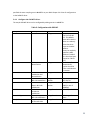
Table 1 summarizes the hardware requirements for Sora.
11
Table 1. Hardware requirements for the Microsoft research Software Radio
CPU/Freq
Memory
PCIe-x8/x16 slot
Hard Disk
Radio hardware
quad-core/2.66GHz (or above)
1GB or above
1
100M of free space
Microsoft Research Software Radio Control
Board (RCB)
Compatible RF front-end boards
(currently, WARP RF daughter board or
USRP XCVR2450 board with respective RF
Adaptor Board)
12
Chapter 2.
Getting Started
2.1
Install Sora SDK
After you download the Sora SDK package, you can simply run SoraSDK.msi and follow the onscreen instructions to install software. The Sora SDK package contains the following components:
The Sora core driver for the RCB.
The HwTest driver - implementing user-mode extension.
UMXSDRab – an 802.11 SDR modem based on UMX Reflection
The sample SoftWiFi driver – a kernel-mode miniport driver implementing full functional
IEEE 802.11a/b/g.
Hardware Verification Tool – helping to test and configure the hardware.
DebugPlot – a graphic tool for real-time monitoring and debugging.
Software oscilloscopes for 802.11a/b/g.
Other samples and tools.
Section 2.5 shows a complete directory tree of the Sora SDK ver 1.7.
2.2
2.2.1
Install RCB Driver and HwTest Driver
Windows 7 Prerequisites
The Sora 64-bit Windows 7 drivers are test-signed by Microsoft Research Asia, so it requires
Test-Signing to be set ON before installed on the target Windows 7 platform. This should be
accomplished by BCDEDIT.EXE, a built-in tool in Windows 7 platform. Please follow the steps
listed below:
1. Run the Command Prompt as administrator
13
2. Execute bcdedit /set TESTSIGNING ON
3. Execute bcdedit for confirmation
4. Restart the system to take effect
14
Now, the target system is ready for installing 64-bit PCIE, HWTest and SDRMiniport test-signed
drivers.
2.2.2
Installation Progress
Before you install the RCB driver, please make sure that the RCB board is firmly plugged into
your motherboard and a RF front-end is properly connected to the RCB. Please follow the
instructions in "Sora Device Drivers Installation.pdf" to install and configure the RCB driver.
Then, you can install the HwTest driver. HwTest implements user-mode extension API that
allows applications to access the Sora radio resource. You can use Windows Device Manager
“Add Hardware Wizard” to install them. You should choose ‘manually add a new driver’ and
specify the driver files location. The binary of the HwTest driver is located at
%SORA_ROOT%\bin\hwtest\.
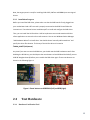
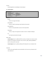
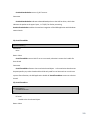
Any time if you want to reset the RCB driver, you should reset the RCB hardware as well. After
disabling the RCB driver, you should press the reset buttons on both RCB and the RAB (if you use
USRP RF daughter boards) before you re-enable the RCB driver again. These reset buttons are
shown in the following Figure 1.
Figure 1. Reset buttons on USRP RAB (left) and RCB (right).
2.3
2.3.1
Test Hardware
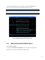
Hardware Verification Tool
15
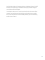
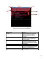
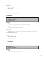
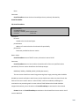
Sora SDK includes a handy tool for testing your hardware: the Hardware Verification Tool (HVT).
HVT allows you to visually verify your RF hardware and tune proper parameter settings (like
central frequency offset and Tx/Rx gains).
You need two Sora boxes to run HVT, one as the sender and the other as the receiver. Before
starting HVT, you should make sure both the RCB driver and the HwTest driver are enabled.
Once you start HVT ( HwVeri.exe is located at %SORA_ROOT%\bin), you will see the following
window, as shown in Figure 2.
16
Table 2 provides a reference to each element on the HVT main window.
u
t
s
r
q
p
a
o
n
b
c
d
e
m
l
f
g
k
h
i
j
Figure 2. The main window of HVT.
17
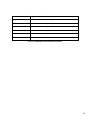
Table 2. HVT Reference.
Label
a
b
c
Name
Test method
selection
Start button
Dump button
d
Suggestion button
e
Auto calibration
button
DC value
Central Frequency
Offset
I/Q imbalance
f
g
h
i
q
Signal-to-Noise
Ratio (SNR)
Status bar
Log window
Save log button
Clear button
Save parameter
button
Load button
AGC
enable/disable
RxPa selection
r
s
t
Sampling rate
Central Frequency
Gain adjustment
u
Mode selection
j
k
l
m
n
o
p
Remark
Select test type (sine test/SNR test).
Start/stop a test.
Take a snapshot of the received signal and save it to a dump file. It
is only available when HVT is working in the receiver mode.
Open a what-to-do document. Only available when HVT is working
in the receiver mode.
Start an automatic central frequency offset (CFO) calibration.
Show the Direct Current value of the received signal.
Show the central frequency offset between the receiver and the
sender.
Show the I/Q imbalance of the received signal (amplitude and
phase). It is only available in the sine test mode.
Show the SNR of the currently received signal. It is only available in
the SNR test mode.
Show the current status message.
Show the full logs during the test.
Save the logs into a text file.
Clear the logs.
Save the parameters into a configuration file.
Load the parameters from a configuration file.
Check/uncheck to enable/disable AGC (Automatic Gain Control).
Select the value for RxPa. RxPa refers to the Low Noise Amplify
(LNA) at the receiving chain of USRP XCRV2450. It has three valid
settings: 0 or 0x1000 – 0dB; 0x2000 – 16dB; 0x3000 – 32dB.
Set the sampling rate of the RAB (40/44MHz).
Select the Central Frequency (channel) of the radio.
Drag to change gain setting. In the sender mode, it changes the Tx
gain; While in the receiver mode, it changes the Rx gain of the radio
chip.
Choose the sender or receiver mode of HVT.
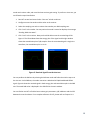
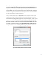
HVT can perform two tests between two Sora boxes: the sine test (single tone test) and the SNR
test (wide-band test). In the sine test, the sender transmits one single 1MHz sine waveform.
Using this waveform, the receiver can compute the Central Frequency Offset (CFO) between the
18
sender and receiver radio, and reveal the best receiver gain setting. To perform a since test, you
can follow the steps listed below:
1. Run HVT on two Sora boxes. Select “sine test” at both machines.
2. Configure one as the sender and the other as the receiver.
3. Select the sampling rate at the receiver that matches your RAB sampling rate.
4. Click “start” at the sender. You may notice the sender’s status bar displays the message
“Sending 1MHz sine wave”.
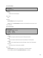
5. Click “start” at the receiver. Now you should be able to see the received signal like
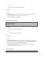
Figure 3. The left window shows the energy plot of the signal and the right window
shows the constellation plot of I/Q samples. Since the transmitted signal is single sine
waveform, the constellation plot is a circle.
Figure 3. Received signal from the sine test.
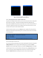
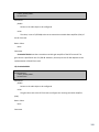
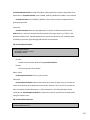
You can perform the SNR test by selecting the SNR test mode and follow the similar steps as in
the sine test. In the SNR test, the sender transmits a wide-band 16-QAM modulated OFDM
signal. Figure 4 shows the received signal in both energy plot and constellation plot in the SNR
test. The actual SNR value is displayed in the SNR field in the main window.
You can further use HVT to find the best receiver gain parameters, I/Q imbalance and the CFO
between the two Sora boxes. For a complete reference of HVT, please refer to Chapter 11.4.
19
Figure 4. Received signal from the SNR test.
2.3.2
Receiving frames from a commercial WiFi card
If you have only a single set of Sora machine, you can use it as the receiver and use a laptop with
WiFi interface as the sender. The laptop should support flexible WiFi configurations (e.g.,
Atheros NIC with MadWiFi driver) because you will need to set it to ad hoc mode with SSID “sdr”
at channel 3 (by default, the HwTest driver configures the RF front-end to channel 3). You will
also need a tool like iperf to send out broadcast packets.
At the Sora machine (receiver), you can use dut.exe to take a snapshot of the channel with the
following command sequence (text following “##” are comments and not meant to be included
in the command line).
dut start
dut centralfreq --value 2422
dut rxpa --value 0x2000
dut rxgain --value 0x1000
dut dump
## start the HwTest driver
## channel 3 in 2.4GHz band
## store a snapshot of channel signal in a dump file
The generated dump file is located at c:\, with the “.dmp” extension. You can easily identify
them by examining the file creation time.
You can use the software oscilloscope tools to view the stored signals. These tools are located at
%SORA_ROOT%\bin. If the source signal is 802.1b (DSSS) signal, you should use sdscope11b.exe to view the recorded signal. Otherwise, you should use sdscope-11a.exe to view OFDM
modulated signals. After you start the software oscilloscope tool (e.g. sdscope-11b.exe), you can
press ‘o’ to bring up an open file dialog window, from which you can select the newly stored
dump file. sdscope-11b decodes and displays the result in screen as shown inFigure 5.
20
To view dumped OFDM signals (802.11g rates of 6Mbps ~ 54Mbps) with sdscope-11a, you
should also specify the sampling rate of the RAB with following command lines,
sdscope-11a.exe -s40
## If your RAB’s sampling rate is 40MSps
or,
sdscope-11a.exe -s44
## If your RAB’s sampling rate is 44MSps
Figure 5. Displaying the dump file with sdscope-11b.
2.4
2.4.1
Build and Install SoftWiFi Driver
Build environment
You need to install Windows Driver Kit (WDK) before you can compile the sample SoftWiFi
miniport Driver. You can download WDK from Microsoft downloads.
21
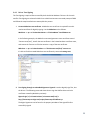
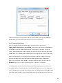
The installer of Sora SDK package has created four shortcuts to build command window in the
start-menu (located in Start\Programs\Microsoft Research Asia\ Software Radio Academic Kit
1.7). Before you can use them, you should configure the WDK path by adding an environment
variable, WINDDK_ROOT. This variable should point to the root path of the WDK. Environment
variables are configured using Windows Control Panel. Figure 6 shows a screen snapshot when
you add a new environment variable on Windows XP.
Then, you can click the menu item of “x64 Free Build” to open a command window. You can
type the command “bcz” to build the SoftWiFi driver (the sample SDR miniport driver), Sora
User-mode Extension (UMX) samples and other tools. All target files (like .exe, .dll, .lib, .sys, etc.)
are generated in the folder %SORA_ROOT%\target\ fre(chk)_wxp(win7)_x86\i386(amd64).
Because the sample SDR miniport driver can be built for both 64bit and 32bit OS, there’re dirs
files for both configuration. Remember to run %SORA_ROOT%\src\set_dirs_x86.cmd before
building the 32bit binaries and run %SORA_ROOT%\src\set_dirs_x64.cmd for 64 bit binaries.
Figure 6. Set WINDDK_ROOT environment variable.
22
2.4.2
Driver Test-Signing
The Test-Signing is required after successfully built the 64-bit Windows 7 drivers. All the tools
used for Test-Signing are released in WDK. Start a build environment command prompt of WDK
and follow the steps listed below to acoomplish the process.
1. Create a MakeCert test certificate. A MakeCert test certificate is required first and is
used as certificate for digitally signing. Use the MakeCert tool as follows:
MakeCert –r –pe –ss TestCertStoreName –n “CN=CertName” CertFileName.cer
In the following example, the MakeCert command generates a test certificate named
“Contoso.com(Test)”, installs the test certificate in the PrivateCertStore certificate store,
and creates the Testcert.cer file that contains a copy of the test certificate.
MakeCert –r –pe –ss PrivateCertStore –n “CN=Contoso.com(Test)” testcert.cer
It’s able to find the created MakeCert test certificate by command certmgr.msc.
2. Test-Signing through an embedded Signature. Signtool is used to digitally sign files, also
the drivers. The following command shows how to sign the HWTest driver with the
certificate created by MakeCert previously.
Signtool sign /v /s PrivateCertStore /n Contoso.com(Test) /t
http://timestamp.verisign.com/scripts/timestamp.dll HWTest.sys
The digital signatures can be found in the property windows of the signed file after
successfully signed.
23
There are still other ways to sign drivers. We just provide 1 here. Please refer the WDK help
documentation for more detail and the parameters for each releated tools.
2.4.3
Install SoftWiFi Driver
After you successfully build the SoftWiFi source, the driver binary is generated at
%SORA_ROOT%\target\fre(chk)_wxp_x86\i386, where you can also find the corresponding inf
file (sdr.inf). You can use “Add Hardware Wizard” to install them on Windows. You should
choose “manually add a new driver” and specify the driver files location. Since the HwTest and
SoftWiFi drivers are contending the hardware resources through the RCB driver, they cannot be
enabled simultaneously. You should disable the HwTest driver before enabling the SoftWiFi
driver. The SoftWiFi driver can be configured into DSSS mode (802.11b) or OFDM mode
(802.11a/g). The default mode is OFDM. To change to a different mode, you can modify the
ModMode registry entry in sdr.inf by specifying value of “802.11a” or “802.11b”.
The SoftWiFi driver exposes an Ethernet interface to the operating system. You can try to use
the SoftWiFi driver to communicate with a commercial WiFi card in real-time. You should make
sure the SoftWiFi driver is configured in a proper mode, i.e. DSSS (802.11b) or OFDM (802.11a/g)
(The default mode is OFDM). If you are using OFDM mode, you should also make sure you have
24
specified the same sampling rate in sdr.inf file as your RAB. Chapter 2.4.4 lists all configurations
to the SoftWiFi driver.
2.4.4
Configure the SoftWiFi driver
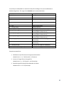
The sample SoftWiFi driver can be configured by editing entries in sdr.inf file.
Table 3. Configuration with SDR.INF.
Entry Name
NetworkAddress
Description
MAC address
Type
String
BSSID
Basic service set
identification
String
ModMode
Protocol of
modulation and
demodulation
Data rate in Mbps in
802.11a modulation
Data rate in 100
kbps in 802.11b
modulation
Modulation option
in 802.11b
modulation
Preamble type in
802.11b modulation
sample rate in MHz
of the radio PCB
String
11ADataRate
DataRate
ModSelect
PreambleType
SampleRate
String of decimal
number
String of hexnumber
String of number
String of number
String of number
Value
The default value is
"02-50-F2-00-0001". This default
value will make the
driver to randomly
select last three
bytes as the MAC
address.
A user can explicitly
specifies a MAC
address if needed
(the last three bytes
cannot be “00-0001”)
The driver will
automatically
replace the value
from a valid beacon
it receives.
802.11a / 802.11b
6 / 9 / 12/ 18 / 24 /
36 / 48 / 54
0x0A / 0x14 / 0x37 /
0x6E (in unit of
100Kbps)
0 for CCK, 1 for PBCC
0 for long, 1 for
short
40 / 44MSps
25
2.5
Directory Structure
The directory structure shown here assumes the Sora SDK is installed at d:\SORASDK1.7
D:\SORASDK1.7
│
│
│
│
AcademicKit-LA.pdf
MSR-LA.pdf
Sample Code-LA.pdf
Readme.htm
Agreement to purchase the academic kit
MSR License agreement
MSR License agreement for the sample source code
The ReadMe file
├─bin
| | dbgplot.exe
│ │ dut.exe
│ │ dot11config.exe
│ │ demod11.exe
│ │ HwVeri.exe
| | umxsdrab.exe
│ │ UMXDot11.exe
│ │ sdscope-11a.exe
│ │ sdscope-11b.exe
│ │ SrView.exe
DbgPlot tool. Refer to Chapter 11.5 for more
information.
Hardware diagnosis tool. Run dut without any command
line parameter for help.
SDR miniport driver configuration tool. See Chapter 9.1
for command line reference. Source code provided
in %SORA_ROOT%\src\driver\SDRMiniport\dot11config
Command line tool to demodulates 802.11a(b) dump
files and displays statistics about data frames. Source
code provided in %SORA_ROOT%\src\bb\demod11
A helpful tool to test and configure Sora hardware
components. Refer to Chapter 11.4 for detail.
User-mode SDR modem for both 802.11ab. It utilizes the
new UMX reflection mechanism. Refer to Chapter 8. For
details. Source code provided
in %SORA_ROOT%\src\umxsdr
User mode 802.11 decoder based on UMX. It has a full
featured 802.11a/b/g decoder. It is also able to
modulate a frame and send it through UMX. Refer to
Chapter 7.4 for detail. Source code provided
in %SORA_ROOT%\src\bb\UMXDot11
User mode utility which demodulates 802.11a frames
from dump file and displays intermediate results in GUI.
Refer to Chapter 10.2 for detail.
User mode utility which demodulates 802.11b
framesfrom dump file and displays intermediate results
in GUI. Refer to Chapter 10.2 for detail.
A simple Sora dump file viewer. See Chapter 10.3 for
detail.
26
│ │ IntFiltr.reg
│ │ IntFiltr.sys
│ │ IntFiltrCmd.exe
│ ├─Config
Interrupt-Affinity Filter registry setting
Interrupt-Affinity Filter driver
Interrupt-Affinity Filter utility
Configuration file used by sdscope-11b
│ ├─ProtocolRunInfo
Configuration file used by sdscope-11b
│ ├─HWTest
Test driver used by the diagnosis tool
│ └─PCIE
Radio Control Board driver
├─build
├─doc
Sora manual and hardware/driver installation guide
├─inc
Software radio framework header files
├─lib
└─src
├─bb
Software radio framework library files
Sora sample code
Baseband library sample
│ ├─Brick11b
802.11b source code, BRICK version
│ ├─dot11a
802.11a source code
│ ├─dot11b
802.11b source code
│ ├─UMXDot11
├─inc
UMX extension, a full featured user mode 802.11 a/b/g
decoder.
Sample tools to modulate/demodulate 802.11a/b frames
Header files used by the 802.11 a/b sample driver
├─kmsdr
Miniport driver sample
│ ├─ll
Link layer
│ ├─mac
Mac layer
│ ├─phy
Physical layer
│ └─demod11
│ └─SDRMiniport
│
├─dot11config
Miniport driver configuration tool
│
├─NDIS5
NDIS5 miniport driver
│
└─NDIS6
├─umxsdr
NDIS6 miniport driver
User mode SDR modem for both 802.11a/b.
└─util
Common utilities used by the 802.11 a/b sample driver
27
Chapter 3.
Sora Fundamentals
3.1
Architecture
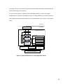
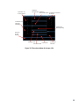
The overall system architecture of Sora is illustrated in Figure 7. The RCB interconnects RF frontends to the PC. The RCB talks to the PC using the PCI-E interface, and with read/write digital
signal samples from/to PC memory using direct memory access (DMA). It connects to the RF
front-end boards with the Sora Fast Radio Link (SoraFRL). SoraFRL defines the necessary
protocol for the RCB to control the RF boards. Any Sora compatible RF boards should implement
SoraFRL. For more information on SoraFRL, please refer to the “Sora Fast Radio Link
Specification”.
Commodity PC
Multi-core CPU
APP
APP
Digital Samples
@Multiple Gbps
APP
APP
RCB
Mem
Sora
Sora
APP
APP
RF
RF
RF
A/D
D/A RF
High throughput
low latency PCIe bus
Software Radio Stack
Figure 7. Sora System Architecture.
Figure 8 shows the Sora software architecture. The RCB driver manages the RCB and RF frontend hardware resources and provides APIs to the SDR miniport driver to send/receive digital
waveform samples. The SDR miniport driver usually exposes an Ethernet interface to the
operating system, so that all network applications can seamlessly use it for communication. In
Sora SDK, a sample SDR miniport driver, named SoftWiFi, is provided, which implements the
28
802.11a/b/g protocol. Alternatively, one can write user-mode SDR application programs that
interact with RCB/RF hardware through Sora User-Mode Extension API (UMX API). Sora SDK
provides a set of highly optimized UMX API to facilitate high performance and low latency DSP
implementation in user-mode, including exclusive thread library, zero-copy sample transport
and integration with network stack. This new UMX framework allows programmers to
implement sophisticated user-mode SDR drivers, and greatly reduces the development efforts.
We provide a sample UMX application that implements a full featured 802.11a/b/g receiver
entirely in user-mode.
User Mode
Sora User-mode
Application
Sora User Mode
Extension
Net
App
Net App
TCP/
IP
Kernel Mode
Sora HWTest Driver
TCP/IP
Sora SDR Miniport Driver
Sora Core API
Radio Control
Board Driver
Net App
Radio Manager
Sora Core API
Tx/Rx Resource
Manager
Radio Control Board(RCB)
PCIe Bus
Figure 8. Sora Software Architecture.
Figure 9 shows the architecture of a typical Sora SDR miniport driver. It usually exposes an
Ethernet interface to the operating system based on the Windows NDIS framework. A SDR
miniport driver should implement the lower three layers, i.e. the link layer, MAC and the
physical layer. The link layer performs the frame conversion and encapsulation. For example, in
the sample SoftWiFi driver, the link layer converts the Ethernet frames to 802.11 frames and
back before and receiving. The MAC layer is basically a finite state machine (FSM) that handles
media access protocols. A set of FSM APIs are provided in Sora SDK to facilitate the MAC
programming. The Physical layer (PHY) contains all implementation of the baseband signal
29
processing. The basic routines that need to be implemented are modulation, demodulation and
channel monitoring (carrier sensing).
For ease of cross-reference, a global context, called SDR_CONTEXT, is used in the sample
SoftWiFi driver to pass data across different layers. This SDR_CONTEXT also contains pointers to
other useful data structures and is used as the sole parameter for many routines in the SoftWiFi
driver.
User Mode
Kernel Mode
TCP/IP
SDR Application Driver
NDIS Wrapper
downlink
uplink
SDR_CONTEXT
Link Layer
Core Library
MAC FSM utility
MAC Layer
Signal Process lib
Physical Layer
(Base band
processing)
Radio Control
Board Driver
Radio Manager
Radio Control Board(RCB)
ethread lib
Sora Core API
Tx/Rx Resource
Manager
PCIe Bus
Figure 9. Typical Architecture of a Sora application Driver.
30
3.2
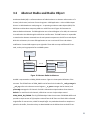
Abstract Radio and Radio Object
An Abstract Radio (AR) is a software abstract of radio hardware. An abstract radio contains a Tx
channel, a Rx channel, and a set of control registers. A SDR application – either a SDR miniport
driver or a UMX-based user-mode program – is operating on abstract radio objects (ARO). The
RCB driver and hardware map every ARO to a real RF front-end. Figure 10 illustrates the
Abstract Radio architecture. If a SDR application sets a Control Register of an ARO, the command
is transferred to the RAB through the RCB driver and firmware. The RAB firmware is responsible
to translate the abstract command into the real operation sequence to the RF front-end chipset.
With this architecture, the same SDR application can ran on various RF front-end without
modification. Current RCB supports up to eight ARs. These ARs can map to different RF frontends, or they can be grouped to form a MIMO system.
SDR Application
RF Adaptor
Abstract Radio
Abstract Control
Registers
Rx Channel
Tx Channel
Sora FRL
Abstract Control
Commands
Radio Specific
Control
Operations
RF RX Channel
RF TX Channel
Figure 10. Abstract Radio Architecture.
An ARO is represented as a SORA_RADIO structure. Figure 11 shows partial definition of the
structure. The full definition of SORA_RADIO can be found in the header file _radio_manager.h.
__ctrl_reg refers to the abstract control registers, _rx_queue manages the Rx channel, and
pTxResMgr manages the TX channel. Each AR is allocated a unique hardware ID as shown in
RadioID. To read from the Rx channel, a SDR driver can use a helper object named
SORA_RADIO_RX_STREAM. The RX_STREAM object hides the structure of RCB DMA buffer and
provides a simple stream of I/Q samples received from the RF front-end. Each ARO is allocated
single buffer for transmission, called TX sample buffer. Any modulated waveform samples are
placed in this buffer, from where they are downloaded into the RCB and sent to the RF front-
31
end. The TX sample buffer is initialized at the beginning and is a shared resource. Therefore,
when the SDR driver uses multiple threads for modulation, the access to the TX sample buffer
from different threads should be properly coordinated by __TxBufLock.
The RCB hardware may also send PnP events to software. These PnP events may be passed to a
SDR driver as well. In particular, two PnP events should be monitored for a SDR driver. They are:
1)
Power management notification. This event is defined as PnPEvent in a SORA_RADIO
object. The SDR driver is encouraged to monitor the event to handle unexpected
disconnection or power outage of the RF radio board.
2)
Force release event. This event is actually generated by the RCB driver when it detects
an abnormal behavior of RCB, or if it is being unloaded. When receiving this event,
the SDR driver should release the resource immediately. The event is shown as
ForceReleaseEvent in the SORA_RADIO definition.
/*
SORA_RADIO defines the basic abstract to a hardware radio.
A Sora radio contains mainly three parts:
1) A Control channel - control registers
2) A Rx channel - Rx queues, further wrapped as rx_stream
3) A Tx channel - Tx buffer, further with Tx resources.
*/
typedef struct __SORA_RADIO
{
LIST_ENTRY
RadiosList;
// control registers
__HW_REGISTER_FILE
__ctrl_reg;
// RX Channel
__RX_QUEUE_MANAGER __rx_queue;
// Reference to shared Tx Resource manager
PTX_RM
pTxResMgr;
ULONG
ULONG
__radio_no; //radio index
RadioID; //unique radio id
__SORA_RADIO_STATUS
__status; // radio status
ULONG
__uRxGain;
ULONG
__uTxGain;
KSPIN_LOCK
LONG
KEVENT
KEVENT
__HWOpLock;//DMA upload and TX lock
__Lock;
ForceReleaseEvent;
PnPEvent;
/* Context - usually linked to a PHY bond on the radio */
PVOID
__pContextExt;
32
// RX_STREAM to access Rx queue DMA Buf
SORA_RADIO_RX_STREAM
__RxStream;
ULONG
volatile BOOLEAN
__fCanWork;
__fRxEnabled;
// TX Channel - Tx Sample Buffer
PTXSAMPLE
__TxSampleBufVa;
PHYSICAL_ADDRESS
__TxSampleBufPa;
ULONG
__TxSampleBufSize;
LONG
__TxBufLock; // Lock to access the Tx sample buffer
//FAST_MUTEX
__ModSampleBufMutex;
} SORA_RADIO, *PSORA_RADIO, **PPSORA_RADIO, __SORA_RADIO, *__PSORA_RADIO;
Figure 11. Definition of the RADIO Object.
3.2.1
Radio Allocation and Release
The SDR driver should allocate abstract radios before accessing the radio resources, e.g., TX
channel, RX channel, or control registers. Abstract radios should also be released to the system
when no longer being used. Function SoraAllocateRadioFromDevice is used to allocate one or
more radios. Prepare a linked list to hold the returned SORA_RADIO objects before calling the
function. A name tag is provided by the caller to track the radio usage.
The SDR driver should call SoraReleaseRadios to release the allocated radio objects.
3.2.2
Radio Configuration and Start
After allocating a radio, the SDR driver should call SoraRadioInitialize to allocate TX and RX
resources for the radio object. After initialization, the SDR driver can call SoraRadioStart to
enable the abstract radio on the RCB. The function call also provides the Tx/Rx gain settings.
3.2.3
Radio example
Figure 12 shows a code piece that illustrates the allocation and initialization of a SORA_RADIO
object. You can find the full function in sdr_phy_main.c in the SDK.
HRESULT
SdrPhyInitialize( PPHY pPhy, PSDR_CONTEXT SDRContext, ULONG ulRadioNum )
{
HRESULT
hRes
= S_OK;
LIST_ENTRY* pRadiosHead = &pPhy->RadiosHead;
…
hRes = SoraAllocateRadioFromRCBDevice (
pRadiosHead,
ulRadioNum,
NIC_DRIVER_NAME);
If ( FAILED (hRes ) )
{
DbgPrint("[Error]SoraAllocateRadioFromRCBDevice failed\n");
33
break;
}
// Successfully allocate radio resource..
hRes = SoraRadioInitialize(
RadioInPHY(pPhy, RADIO_RECV), // Get the radio in PHY list
NULL, // reserved
SAMPLE_BUFFER_SIZE, // buffer size for TX
RX_BUFFER_SIZE);
FAILED_BREAK(hRes);
// Start radio
hRes = SoraRadioStart(
RadioInPHY(pPhy, RADIO_RECV),
SORA_RADIO_DEFAULT_RX_GAIN,
SORA_RADIO_DEFAULT_TX_GAIN,
NULL);
FAILED_BREAK(hRes);
…
return hRes;
}
Figure 12. Radio allocation and initialization.
3.3
Transfer and Transmission
Before sending out a waveform, a SDR driver should first download the waveform samples onto
the onboard memory of the RCB. Then, the SDR driver can issue another command to instruct
the RCB to emit the waveform through the RF front-end. The download operation is referred as
transfer, and we denote transmission (or simply TX) the behavior the send out waveform. The
benefits of this two-phase operation are two-folds. First, the RCB’s on-board memory naturally
absorbs the potential burstiness of the CPU processing and the PCIe-Bus communication,
thereby ensuring the correctness of the waveform transmission. Second, the RCB memory can
also be used to store pre-modulated signals, providing additional flexibility.
3.3.1
PACKET_BASE object
A SDR driver uses a PACKET_BASE object to allocate TX resources of an abstract radio object.
The PACKET_BASE object also contains a pointer to the original packet data. Figure 13 shows the
definition of the PACKET_BASE object, which can also be found in _packet_base.h.
34
typedef struct __PACKET_BASE
{
PMDL
pMdl;
// memory descriptors for original packet data
PTX_DESC
pTxDesc;
// Refers to TX channel of an Abstract Radio
LONG
fStatus;
ULONG
PacketSize;
ULONG
Reserved1; //for customized attachment
ULONG
Reserved2; //for customized attachment
ULONG
Reserved3; //for customized attachment
ULONG
Reserved4; //for customized attachment
PVOID
pReserved;
} PACKET_BASE;
Figure 13. Definition of PACKET_BASE ojbect.
A PACKET_BASE object has a pointer to a Memory Descriptor List (MDL) that describes the data
in the original packet. MDL is a common data structure in the Windows kernel to describe a
memory buffer. For more information of the MDL, the reader may refer to WDK references.
The fStatus field tracks the packet’s current status. The SDR application driver should check this
status before conducting operations on it. The status can be one of following:
PACKET_NOT_MOD: The modulated waveform of the packet has not been generated.
PACKET_TF_FAIL: The Transfer operation failed.
PACKET_CAN_TX: The Transfer operation succeeded. So the modulated waveform is not
in the RCB Waveform Cache and is ready for Transmission.
PACKET_TX_PEND: The modulated waveform is being transmitted.
PACKET_TX_DONE: The Transmission is done.
If a PACKET_BASE object is in the PACKET_TF_FAIL state, the SDR driver should not attempt to
transmit it.
3.3.2
Modulation
A SDR driver should call SoraPacketGetTxResource to bind a PACKET_BASE object to the TX
channel for a radio. SoraPacketGetTxResource will initialize the status to PACKET_NOT_MOD.
Then, the SDR driver can call SoraPacketGetTxSampleBuffer to obtain a sample buffer to hold
the waveform generated. The structure of this modulation sample buffer is shown in Figure 14.
It is basically an array of complex I/Q samples. Each I and Q component is 8-bit. The sample with
the smallest address is transmitted first by the RF front-end board.
35
re0
im0
re1
im1
rei
imi
Rei+1 imi+1
Figure 14. Structure of the TX sample buffer.
Once the SDR driver gets the modulation sample buffer, it should immediately generate
waveform samples from the packet data (modulation). The SDR application driver should call
SoraPacketSetSignalLength to specify the size of the buffer that is actually filled with the
waveform samples. The size MUST be a multiple of 128 bytes. Therefore, some padding may be
needed to ensure this.
3.3.3
Transfer and Transmission
A SDR driver calls SORA_HW_TX_TRANSFER to download the waveform samples from the Tx
sample buffer to the RCB’s memory. After the transfer operation, the SDR driver can call
SORA_HW_BEGIN_TX to instruct the RCB to send out the waveform. After the transmission, the
SDR application driver should call SoraPacketFreeTxResource to unbind the PACKET_BASE
object from the radio’s TX channel.
3.3.4
Example
Figure 15 shows a code excerpt for an SDR application driver to bind packets to the radio TX
channel and call PHY layer functions to modulate the packet data to waveform samples. The full
code can be found in sdr_mac_send.c. Figure 16 shows an excerpt where an SDR application
driver instructs the RCB to transmit a waveform already stored in the RCB’s memory. The full
code can be found in sdr_mac_tx.c.
VOID SdrMacSendThread ( IN PVOID pVoid )
{
NTSTATUS Status;
HRESULT hRes;
LARGE_INTEGER Delay;
PDLCB pTCB = NULL;
PSDR_CONTEXT pSdrContext =
SORA_THREAD_CONTEXT_PTR(SDR_CONTEXT, pVoid);
PMAC pMac = (PMAC)pSdrContext->Mac;
PPHY pPhy = (PPHY)pSdrContext->Phy;
PSEND_QUEUE_MANAGER
pSendQueueManager = GET_SEND_QUEUE_MANAGER(pMac);
PSORA_RADIO
pRadio
= NULL;
// Thread start
…
Delay.QuadPart = -10 * 1000 * 10;
36
do
{
…
pRadio = RadioInPHY(pPhy, RADIO_SEND);
do
{
// Try to dequeue a pending packet and do modulation
SafeDequeue(pSendQueueManager, SendSrcWaitList, pTCB, DLCB);
if (!pTCB)
{
break;
}
if (!DLCB_CONTAIN_VALID_PACKET(pTCB)) // invalid packet, pass through the pipeline
{
SafeEnqueue(pSendQueueManager, SendSymWaitList, pTCB);
InterlockedIncrement(&pSendQueueManager->nSymPacket);
InterlockedDecrement(&pSendQueueManager->nSrcPacket);
continue;
}
// Allocate Tx Channel Resource for a packet
if (IS_PACKET_NO_RES(&pTCB->PacketBase))
{
hRes = SoraPacketGetTxResource(pRadio, &pTCB->PacketBase);
if (FAILED(hRes))
{
InterlockedIncrement(&pSendQueueManager->nSymPacket);
InterlockedDecrement(&pSendQueueManager->nSrcPacket);
SafeEnqueue(pSendQueueManager, SendSymWaitList, pTCB); // let it go
DbgPrint("[Transfer][Error] insufficient TX resource \n");
break;
}
}
else
{
KeBugCheck(BUGCODE_ID_DRIVER); //src packet should not own TX resource.
}
// Call PHY Modulation Routine
hRes = (*pPhy->FnPHY_Mod)(pPhy, &(pTCB->PacketBase));
// Transfer operation
hRes = SORA_HW_TX_TRANSFER( pRadio, &pTCB->PacketBase);
SoraPacketAssert(&pTCB->PacketBase, pRadio); //for verification.
if (FAILED(hRes))
{
SoraPacketPrint(&pTCB->PacketBase);
SoraPacketFreeTxResource(pRadio, &pTCB->PacketBase);
InterlockedIncrement(&pPhy->HwErrorNum);
}
SafeEnqueue(pSendQueueManager, SendSymWaitList, pTCB);
InterlockedIncrement(&pSendQueueManager->nSymPacket);
InterlockedDecrement(&pSendQueueManager->nSrcPacket);
//both case: let the packet go.
} while (TRUE);
}while(!IS_SORA_THREAD_NEED_TERMINATE(pVoid));
// Thread cleanup
…
}
37
Figure 15. Modulation and transfer.
VOID
SdrMacTx(IN PFSM_BASE StateMachine)
{
HRESULT
hRes
= S_OK;
PSDR_CONTEXT pSDRContext = SoraFSMGetContext(StateMachine);
PMP_ADAPTER
pAdapter
= (PMP_ADAPTER)pSDRContext->Nic;
PMAC
pMac = (PMAC)pSDRContext->Mac;
PPHY
pPhy = (PPHY)pSDRContext->Phy;
PSEND_QUEUE_MANAGER
pSendQueueManager = GET_SEND_QUEUE_MANAGER(pMac);
PSORA_RADIO pRadio = RadioInPHY(pPhy, RADIO_SEND);
PDLCB
pTCB = NULL;
do
{
SafeDequeue(pSendQueueManager, SendSymWaitList, pTCB, DLCB);
if (!pTCB)
{
break;
}
if (pTCB->PacketBase.fStatus == PACKET_TF_FAIL) //The packet can't be TX out, so complete it.
{
DbgPrint("[TX][Error] I can't tx it out because transfer fail, make it TXDone to complete\n");
// skip the packet
…
break;
}
pMac->fTxNeedACK = (pTCB->PacketType == PACKET_NEED_ACK);
pTCB->RetryCount++;
// Start transimission
hRes = SORA_HW_BEGIN_TX(pRadio, &pTCB->PacketBase);
if (FAILED(hRes))
{
DbgPrint("[TX][Error] TX hardware error , ret=%08x\n", hRes);
SoraHwPrintDbgRegs(pRadio);
InterlockedIncrement(&pPhy->HwErrorNum);
}
if ( !IS_MAC_EXPECT_ACK(pMac) || pTCB->RetryCount > TX_RETRY_TIMEOUT)
{
pTCB->bSendOK = (pTCB->RetryCount <= TX_RETRY_TIMEOUT);
// if retry is not so big, assume it is sent out successufully.
SoraPacketFreeTxResource(pRadio, &pTCB->PacketBase);
SoraPacketSetTXDone(&pTCB->PacketBase);
InterlockedIncrement(&pSendQueueManager->nCompletePacket);
InterlockedDecrement(&pSendQueueManager->nSymPacket);
SafeEnqueue(pSendQueueManager, SendCompleteList, pTCB);
//MarkModulatedSlotAsTxDone(pSendQueueManager); //dequeue the packet from send queue
SDR_MAC_INDICATE_PACKET_SENT_COMPLETE(pMac); //indicate to complete NDIS_PACKET
MAC_DISLIKE_ACK(pMac); // we don't need ACK any more.
}
else
{
SafeJumpQueue(pSendQueueManager, SendSymWaitList, pTCB);
//wait for ack to retry or complete
}
38
} while (FALSE);
SoraFSMGotoState(StateMachine, Dot11_MAC_CS);
return;
}
Figure 16. Waveform transmission and cleanup.
3.4
Reception
The RX channel of a radio is enabled by SORA_HW_ENABLE_RX. The SDR driver can read the RX
channel through an RX_STREAM object. The SDR driver can obtain a RX_STREAM object by
calling SoraRadioGetRxStream. The RX channel of a radio is organized as a stream of signal
blocks. Each signal block contains an array of 28 complex I/Q samples. The I or Q component are
both 16-bit long. Figure 17 shows the structure of a signal block. Function
SoraRadioReadRxStream loads a signal block into memory. It is blocking function that will not
return until a full signal block is delivered from the RCB (or timeout). The pbTouched flag is set
when the returned signal block is the last block in the RX channel, ie. the most recently received
signal block. The SDR driver can use SoraRadioGetRxStreamPos to obtain the current position of
the RX channel, and use SoraRadioSetRxStreamPos to change the current position of the RX
channel.
39
RX_DESC (16 bytes)
RX_BLOCK
I0
Q0
I1
Q1
SignalBlock
I 27
Q 27
16 bits
16 bits
Figure 17. Structure of a signal block.
3.4.1
Example
Figure 18 shows sample code to read from an RX_STREAM object. The full code can be found in
bbb_spd.c.
HRESULT BB11BSpd(PBB11B_SPD_CONTEXT pSpdContext, PSORA_RADIO_RX_STREAM
pRxStream)
{
// ...
FLAG touched;
ULONG PeekBlockCount = 0;
HRESULT hr
= S_OK;
SignalBlock block;
do
{
// ...
while (TRUE)
{
hr = SoraRadioReadRxStream(pRxStream, &touched, block);
FAILED_BREAK(hr);
// Estimate and update DC offset
// ...
PeekBlockCount++;
// Measure energy
// ...
if (energyLevel != EL_NOISE)
{
if (pSpdContext->b_gainLevel == 0 && energyLevel == EL_HIGH)
pSpdContext->b_gainLevelNext = 1;
else if (pSpdContext->b_gainLevel == 1 && energyLevel == EL_LOW)
pSpdContext->b_gainLevelNext = 0;
40
pSpdContext->b_evalEnergy = BlockEnergySum[0];
hr = BB11B_OK_POWER_DETECTED;
break;
}
if (touched && PeekBlockCount > pSpdContext->b_minDescCount)
{
hr = BB11B_CHANNEL_CLEAN;
break;
}
if (PeekBlockCount >= pSpdContext->b_maxDescCount)
{
hr = BB11B_E_PD_LAG;
break;
}
}
} while(FALSE);
// ...
return hr;
}
Figure 18. Example code to read from RX_STREAM.
41
Chapter 4.
MAC Programming
Sora provides a utility library to program a Finite State Machine (FSM). An FSM is commonly
used in the MAC and other protocol implementations. For example, Figure 19 shows a simplified
MAC state-machine of 802.11 that contains three states: carrier sense, transmission (TX) and
reception (RX).
le
D
x
R
Rx
e/
on
D led
Tx Fai
P
De owe
tec r
ted
on
e/
Fa
i
Carrier Sense
d
an
g e
i n re
nd el F
Pe nn
Tx ha
C
d
Channel Free
Tx
Figure 19. A simplified MAC state machine of 802.11.
4.1
State Machine declaration and
initialization
The SDR driver declares an FSM through SORA_BEGIN_DECLARE_FSM_STATES,
SORA_END_DECLARE_FSM_STATES, and SORA_DECLARE_STATE. After that, the SDR driver
should further declare an FSM type using SORA_DECLARE_FSM_TYPE. An FSM instance can
then be declared for this FSM type. Each state of an FSM is associated with a state handler. At
initialization, the SDR driver should assign these handers to an FSM instance using
SORA_FSM_ADD_HANDLER.
42
In Sora, a state machine may usually run in an exclusive thread that provides real-time support.
The SDR driver uses SORA_FSM_CONFIG to assign a parameter to the FSM instance, which will
be passed to each state handler. This parameter is usually a pointer to SDR_CONTEXT. During
initialization, one should also specify the initial state on which the FSM starts using
SoraFSMSetInitialState.
Figure 20 shows an excerpt from sdr_mac.h to declare the simplified 802.11 MAC FSM. Figure
21 shows sample code from sdr_mac_main.c to initialize an FSM instance declared as a member
of the PMAC object.
// Declare MAC FSM states for 802.11
SORA_BEGIN_DECLARE_FSM_STATES(Dot11)
SORA_DECLARE_STATE(Dot11_MAC_CS)
SORA_DECLARE_STATE(Dot11_MAC_TX)
SORA_DECLARE_STATE(Dot11_MAC_RX)
SORA_END_DECLARE_FSM_STATES(Dot11)
// Declare a FSM structure type for 802.11
SORA_DECLARE_FSM_TYPE(DOT11FSM, Dot11)
Figure 20. Example to declare an 802.11 MAC state machine.
VOID
SdrMacInitStateMachine(IN PMAC pMac, IN PSDR_CONTEXT SDRContext)
{
// Associate the real state handlers to the FSM
SORA_FSM_ADD_HANDLER(pMac->StateMachine, Dot11_MAC_CS, SdrMacCs);
SORA_FSM_ADD_HANDLER(pMac->StateMachine, Dot11_MAC_TX, SdrMacTx);
SORA_FSM_ADD_HANDLER(pMac->StateMachine, Dot11_MAC_RX, SdrMacRx);
SORA_FSM_CONFIG (pMac->StateMachine, SDRContext, 0);
// Set the initial start state
SoraFSMSetInitialState ((PFSM_BASE)&pMac->StateMachine, Dot11_MAC_CS);
}
Figure 21. Initializing an FSM.
4.2
FSM Start, Stop, and State Transition
To start an FSM, the SDR driver should call SoraFSMStart, which starts the state machine in an
exclusive thread.
43
A call of SoraFSMStop from any state handler terminates the FSM. SoraFSMGotoState is called
before exiting the current state handler to transit to other states. The state handler of the new
state will be invoked by the FSM thread.
4.2.1
Example
Figure 22 shows an example state handler from sdr_mac_cs.c for carrier sense. It enters
different states based on the result of the PHY sensing function.
VOID
SdrMacCs(IN PFSM_BASE StateMachine)
{
HRESULT hRes
= S_OK;
//Get SDR context initialized by SORA_FSM_CONFIG;
PSDR_CONTEXT pSDRContext = (PSDR_CONTEXT)SoraFSMGetContext(StateMachine);
// Get all references from SDR context
PMP_ADAPTER pAdapter = (PMP_ADAPTER)pSDRContext->Nic; //initialized by SdrContextBind;
PMAC pMac = (PMAC)pSDRContext->Mac; //initialized by SdrContextBind;
PPHY pPhy = (PPHY)pSDRContext->Phy; //initialized by SdrContextBind;
PSORA_RADIO pRadio = NULL;
…
pRadio = RadioInPHY(pPhy, RADIO_RECEIVE);
if(!SoraRadioCheckRxState(pRadio))
{
DbgPrint("[MAC_CS] enable Rx for the first time\n");
SORA_HW_ENABLE_RX(pRadio);
}
if (pPhy->HwErrorNum > HW_ERROR_THRESHHOLD)
{
DbgPrint("[Error] Reset MAC send \n");
InterlockedExchange(&pPhy->HwErrorNum, 0);
//SdrMacResetSend(pMac);
}
if(pMac->fDumpMode)
{
_Dump(pMac, pRadio);
}
hRes = PhyDot11BCs(pPhy, RADIO_SEND);
if (hRes == E_FETCH_SIGNAL_HW_TIMEOUT)
{
DbgPrint("[MAC_CS][Error] E_FETCH_SIGNAL_HW_TIMEOUT \n");
}
switch (hRes)
{
case BB11B_CHANNEL_CLEAN:
if (IS_MAC_EXPECT_ACK(pMac))
{
hRes = __ExpectAck(pPhy);
if (hRes != BB11B_OK_POWER_DETECTED)
44
{
DbgPrint("[MAC_CS][Error] Ack detect fail, we don't need ACK anymore \n");
MAC_DISLIKE_ACK(pMac);
}
else
{
SoraFSMGotoState(StateMachine, Dot11_MAC_RX);
return;
}
}
DbgPrint("[MAC_CS] channel clean, goto tx \n");
SoraFSMGotoState(StateMachine, Dot11_MAC_TX);
return;
case BB11B_OK_POWER_DETECTED:
SoraFSMGotoState(StateMachine, Dot11_MAC_RX);
return;
case E_FETCH_SIGNAL_HW_TIMEOUT: //Hardware error
SoraFSMGotoState(StateMachine, Dot11_MAC_TX);
DbgPrint("[Error] E_FETCH_SIGNAL_HW_TIMEOUT \n");
//InterlockedIncrement(&pMac->pPhy->HwErrorNum);
break;
default:
DbgPrint("[MAC_CS] CS return %x\n", hRes);
break;
}
}
Figure 22. An example state handler for Carrier Sense.
45
Chapter 5.
Real-Time Support
5.1
Using Sora thread
Sora supports real-time behavior via exclusive threading. An exclusive thread (or ethread) is a
non-interruptible thread running on a multi-core system. In previous versions, an exclusive
thread is bound to a dedicated CPU core and the programmer should manually assign CPU cores.
Since Sora SDK version 1.5, the core assignment is performed by the library that dynamically
allocates CPU cores to ethreads.
The SDR driver should allocate an ethread object by calling SoraThreadAlloc. Then, the SDR
driver can call SoraThreadStart to start the ethread. SoraThreadStart takes three parameters: a
valid ethread handle, a user-defined thread routine, and a user-defined parameter passed to the
thread routine. If the return value of the thread routine is FALSE, the ethread will be terminated;
otherwise, the routine will be called from the Sora core library after it re-computes the best core
allocation and reassigns each ethread to a proper core. Since the ethreads are scheduled in a
cooperative way, the ethread routine must return periodically (usually when critical tasks are
done). Note that the dynamic scheduling of ethread imposes minimal overhead.
To terminate an ethread, one should call SoraThreadStop. It should be note it is prohibitive to
call any Sora Thread API from the ethread routine; otherwise, a deadlock will occur. To exit from
the thread, a user-defined routine should return with a FALSE value.
Comments: For user mode applications, the corresponding thread APIs are SoraUThreadAlloc,
SoraUThreadStart, SoraUThreadStop and SoraUThreadFree.
Figure 23 shows code excerpts from sdr_phy_main.c to initialize and start a Sora thread that
performs Viterbi decoding.
HRESULT
SdrPhyInitialize(
46
IN PPHY
pPhy,
IN PSDR_CONTEXT SDRContext,
IN ULONG
ulRadioNum)
{
…
if (pPhy->PHYMode == DOT_11_A) {
hRes = NDIS_STATUS_FAILURE;
pPhy->Thread = SoraThreadAlloc();
if (pPhy->Thread)
if (SoraThreadStart(pPhy->Thread, viterbi_proc, &pPhy->BBContextFor11A.RxContext))
hRes = NDIS_STATUS_SUCCESS;
if (hRes != NDIS_STATUS_SUCCESS)
if (pPhy->Thread) {
SoraThreadFree(pPhy->Thread);
pPhy->Thread = NULL;
}
}
…
}
BOOLEAN viterbi_proc(PVOID pVoid) {
BB11ARxViterbiWorker(pVoid);
return *((PBB11A_RX_CONTEXT)pVoid)->ri_pbWorkIndicator;
}
Figure 23. Using Sora thread.
Figure 24 shows the sample code of a Viterbi work routine from arx_bg1.c. The function calls
different Viterbi decoding modules based on the data rate. It starts by checking if there is work
to do. If not, the routine will immediately return. Otherwise, it will accept the work by clearing
the flag and perform the decoding task. After decoding, the routine returns to the state waiting
for a new task.
void BB11ARxViterbiWorker(PVOID pContext)
{
PBB11A_RX_CONTEXT pRxContextA = (PBB11A_RX_CONTEXT)pContext;
if (BB11A_VITERBIRUN_WAIT_EVENT(pRxContextA))
{
BB11A_VITERBIRUN_CLEAR_EVENT(pRxContextA);
pRxContextA->bCRCCorrect = FALSE;
switch (pRxContextA->bRate & 0x7)
{
case 0x3:
VitDesCRC6(pRxContextA);
break;
case 0x7:
VitDesCRC9(pRxContextA);
break;
case 0x2:
VitDesCRC12(pRxContextA);
break;
47
case 0x6:
VitDesCRC18(pRxContextA);
break;
case 0x1:
VitDesCRC24(pRxContextA);
break;
case 0x5:
VitDesCRC36(pRxContextA);
break;
case 0x0:
VitDesCRC48(pRxContextA);
break;
case 0x4:
VitDesCRC54(pRxContextA);
break;
}
_mm_mfence();
BB11A_VITERBIDONE_SET_EVENT(pRxContextA);
}
}
Figure 24. Example ethread routine.
5.2
Interrupt affinity
With ethread, the SDR application driver can prevent the task from being preempted by other
threads. But the task may still be interrupted by hardware. Although most hardware interrupt
handlers are very light-weight, some may still require a significant amount of time to finish (e.g.,
disk access) and thus cause a real-time task to miss deadlines. To address this issue, one could
set the interrupt affinity for all hardware devices to avoid sending interrupts to the reserved
core. On Windows 7, the interrupt affinity can be configured via the registry. But there is no
native support on Windows XP. The Sora SDK includes a tool, called interrupt filter, which can
configure the interrupt affinity of hardware devices. The tool can be found in %SDR_ROOT%\bin
folder.
5.2.1
Installing and Configuring Interrupt Filter
To install the interrupt filter driver, first copy intfiltr.sys to Windows system driver folder (e.g.,
c:\windows\system32\drivers). Then, add the registry entries specified in intfiltr.reg, and, finally,
reboot the machine to enable the interrupt filter driver.
D:\SoraSDK\bin>IntFiltrCmd.exe
48
-a :
Add interrupt affinity set filter driver
-r :
Remove interrupt affinity set filter driver
-m affinity mask :
Specify the affinity mask
Figure 25. Help page of intfiltrcmd.exe.
You can configure the interrupt affinity using intFiltrCmd.exe. Type intfiltrcmd, and you can see
the help page shown in Figure 25. The default interrupt affinity is 0xFFFFFFFF, meaning all cores
can be interrupted. You can turn off the bits corresponding to the reserved cores and specify the
new affinity using command
Intfiltrcmd –a –m <core affinity that allows to be interrupted>
To remove the affinity (or reset to default), run
Intfiltrcmd –r
49
Chapter 6.
Signal Cache
One key design choice for the Sora system is to provide a large on-board memory on the RCB.
This on-board memory can serve as a cache for pre-generated signals. The SDR driver can call
SoraInitSignalCache to initialize a SIGNAL_CACHE structure. After initialization, a portion of the
RCB memory is allocated to the signal cache and the SDR driver can store signals in it. The cache
is organized into a number of equal size slots.
SoraInsertSignal adds a signal to a cache entry that is indicated by an 8-byte hash key. The signal
can be later retrieved using this hash key by calling SoraGetSignal. If the signal exists in the
cache, SoraGetSignal returns a TX_DESC of the signal, which can be passed to
SORA_HW_FAST_TX to send out the stored signal.
The SDR driver must clean up the cache before it is unloaded or the cache is no longer used.
SoraCleanSignalCache will release all resources allocated.
6.1
Example
In the Sora 802.11 sample driver, a signal cache is used to store ACK frames to corresponding
senders. It defines an ACK_CACHE_MAN structure that is inherited from the SIGNAL_CACHE.
Figure 26 shows the initialization function of the ACK cache from sdr_phy_ack_cache.c. The
function tries to allocate a SIGNAL_CACHE from the RCB onboard memory.
HRESULT SdrPhyInitAckCache(
OUT PACK_CACHE_MAN pAckCacheMan,
IN PDEVICE_OBJECT pDeviceObj,
IN PPHY pOwnerPhy,
IN PSORA_RADIO pRadio,
IN ULONG MaxAckSize,
IN ULONG MaxAckNum
)
{
HRESULT hr;
PHYSICAL_ADDRESS
PHYSICAL_ADDRESS
PhysicalAddress
= {0, 0};
PhysicalAddressLow = {0, 0};
50
PHYSICAL_ADDRESS
PhysicalAddressHigh = {0x80000000, 0};
NdisZeroMemory(pAckCacheMan, sizeof (ACK_CACHE_MAN)); //constructor
NdisInitializeEvent(&pAckCacheMan->RemoveEvent);
NdisAllocateSpinLock(&pAckCacheMan->ReqQueueLock);
pAckCacheMan->pOwnerPhy = pOwnerPhy;
do {
hr = SoraInitSignalCache (&pAckCacheMan->AckCache,
pRadio,
MaxAckSize,
MaxAckNum);
FAILED_BREAK(hr);
pAckCacheMan->pAckModulateBuffer
= MmAllocateContiguousMemorySpecifyCache(
MaxAckSize ,
PhysicalAddressLow,
PhysicalAddressHigh,
PhysicalAddress,
MmNonCached
);
if (pAckCacheMan->pAckModulateBuffer == NULL)
{
hr = E_NOT_ENOUGH_RESOURCE;
break;
}
pAckCacheMan->AckModulateBufferPA =
MmGetPhysicalAddress((PVOID)pAckCacheMan->pAckModulateBuffer);
pAckCacheMan->AckModulateBufferSize = MaxAckSize;
…
}while(FALSE);
MP_INC_REF(pAckCacheMan);
if (FAILED(hr))
{
SdrPhyCleanupAckCache(pAckCacheMan);
}
return hr;
}
Figure 26. ACK_CACHE_MAN initialization.
When MAC detects that a required ACK frame is not in the cache, it will queue a request, wake
up a worker thread that does the modulation, and insert the generated waveform in the ACK
Cache. The key to identify the frame is the MAC address of the destination. Figure 27 shows the
sample code from sdr_phy_ack_cache.c.
VOID AckCacheMakeThread(
IN PDEVICE_OBJECT DeviceObject,
IN PVOID Context )
{
51
PACK_CACHE_MAN pAckCacheMan = (PACK_CACHE_MAN)Context;
MAC_ADDRESS MacAddr;
PHY_FRAME_KEY Key;
ULONG Length = 0;
HRESULT hr;
UNREFERENCED_PARAMETER(DeviceObject);
MP_INC_REF(pAckCacheMan);
do
{
int i;
__Dequeue(pAckCacheMan, &MacAddr);
Key.QuadKey.u.HighPart = 0;
Key.QuadKey.u.LowPart = 0;
for (i = 0; i < MAC_ADDRESS_LENGTH; i++)
{
Key.KeyBytes[i] = MacAddr.Address[i];
}
Length = SdrPhyModulateACK(
MacAddr,
pAckCacheMan->pAckModulateBuffer);
hr = SoraInsertSignal (
&pAckCacheMan->PhyAckCache,
pAckCacheMan->pAckModulateBuffer,
&pAckCacheMan->AckModulateBufferPA,
Length,
Key);
if (hr == E_TX_TRANSFER_FAIL)
{
DbgPrint("[TEMP1] Ack insert cache failed, return 0x%08x\n", hr);
InterlockedIncrement(&pAckCacheMan->pOwnerPhy->HwErrorNum);
}
else
{
DbgPrint("[TEMP1] Ack insert cache succ, return 0x%08x\n", hr);
}
}while(InterlockedDecrement(&pAckCacheMan->PendingReqNum) != 0);
MP_DEC_REF(pAckCacheMan);
return;
}
Figure 27. Modulate an ACK and insert the waveform in the signal cache.
52
Chapter 7.
User-Mode Extension
Sora provides a new programming model, called User-Mode eXtension (UMX), which allows
user-mode applications to access the radio resources. With UMX APIs, developers can write
baseband processing in user-mode, and therefore the programming and debugging efforts are
greatly reduced.
7.1
UMX Initialization and Configuration
UMX is based on the HWTest driver (see also Chapter 11. ), as shown in Figure 28.
Figure 28. Architecture of Sora UMX.
The UMX application initializes UMX library with SoraUInitUserExtension. The function needs
the device name of the HWTest driver, which is “\\.\HWTest”. HWTest will allocate an abstract
radio from the RCB, and the UMX application can configure the radio parameters using the
corresponding APIs. After the radio is properly configured, the UMX application can start the
radio by calling SoraURadioStart. Before exiting, the SDR application should call
SoraUCleanUserExtension to clean up the resource that has been allocated.
53
Figure 29 shows the sample code that initializes and configures UMX.
void RadioConfig()
{
SoraURadioStart(TARGET_RADIO);
SoraURadioSetRxPA (TARGET_RADIO, SORA_RADIO_DEFAULT_RX_PA);
SoraURadioSetRxGain (TARGET_RADIO, SORA_RADIO_DEFAULT_RX_GAIN);
SoraURadioSetTxGain (TARGET_RADIO, SORA_RADIO_DEFAULT_TX_GAIN);
SoraURadioSetCentralFreq (TARGET_RADIO, 2422 * 1000);//central frequency: 2422MHz
SoraURadioSetFreqOffset (TARGET_RADIO, -5 * 1000 * 1000); //frequency offset: -5MHz
SoraURadioSetSampleRate (TARGET_RADIO, 40); //sample rate: 40MHz
}
int __cdecl main(int argc, char *argv[])
{
BOOLEAN isTx = FALSE;
// Initialize Sora user mode extension
BOOLEAN succ = SoraUInitUserExtension("\\\\.\\HWTest");
if (!succ)
{
printf("Error: fail to find a Sora UMX capable device!\n");
return -1;
}
RadioConfig();
…
SoraUCleanUserExtension();
return 0;
}
Figure 29. Sample code to initialize and configure UMX.
7.2
Reception
To access the RX channel of a radio object, the UMX application should first call
SoraURadioMapRxSampleBuf to obtain a pointer to the receiving buffer as well as the buffer
size. Then, the UMX application can get a RX_STREAM from the receiving buffer using
SoraURadioAllocRxStream, from which it can read I/Q samples. To read a signal block, the UMX
application needs to call SoraRadioReadRxStream. Before exiting, the UMX application should
call SoraURadioReleaseRxStream to release a RX_STREAM and SoraURadioUnmapRxSampleBuf
to release the memory mapped to the RX buffer of a radio.
Figure 30 shows an example to receive I/Q samples using UMX.
54
void RxRoutine ()
{
PVOID pRxBuf = NULL;
ULONG nRxBufSize = 0;
HRESULT hr;
…
SORA_RADIO_RX_STREAM SampleStream;
//
// Map Rx Buffer
//
hr = SoraURadioMapRxSampleBuf (
TARGET_RADIO, // radio id
& pRxBuf, // mapped buffer pointer
& nRxBufSize // size of mapped buffer
);
if ( FAILED (hr) ) {
printf ( "Error: Fail to map Rx buffer!\n" );
return;
}
printf ( "Mapped Rx buffer at %08x size %d\n", pRxBuf, nRxBufSize );
// Generate a sample stream from mapped Rx buffer
SoraURadioAllocRxStream( &SampleStream,
TARGET_RADIO,
(PUCHAR)pRxBuf,
nRxBufSize );
// start reading the sample stream and compute the energy
FLAG fReachEnd;
int index = 0;
SignalBlock block;
…
for (;;)
{
hr = SoraRadioReadRxStream(
& SampleStream,
// current scan point
& fReachEnd, // indicate if end of stream reached (you must wait for hardware)
block);
if (FAILED(hr))
{
printf("stream ended, hr=%08x\n", hr);
break;
}
QueryPerformanceCounter(&End);
if (End.QuadPart - Start.QuadPart > Freq.QuadPart / 2)
{
Start = End;
// almost 1s
// compute the energy
vcs* pSamples = &block[0];
// single block contains 28 samples or 7 vector cs
vi sum;
set_zero (sum);
// this is an approximated way to calc energy
for (int i=0; i<7; i++ ) {
55
vi re, im;
vcs s = pSamples[i];
s = shift_right (s, 3);
conj_mul ( re, im, s, s ); // (a+bj) * (a-bj)
sum = add (sum, re );
}
sum = hadd (sum); // get a sum of the all element on the vector
int energy = sum[0];
printf("
\r"); //clean the line.
printf ( "%d --> Energy %10d \r", index++, energy / 1000);
}
}
SoraURadioReleaseRxStream(&SampleStream, TARGET_RADIO);
if (pRxBuf) {
hr = SoraURadioUnmapRxSampleBuf (TARGET_RADIO, pRxBuf);
}
printf("Unmap hr:%08x\n", hr);
}
Figure 30. Sample routine for receiving using UMX.
7.3
Transmission
To transmit waveform using UMX, the UMX application should allocate the Tx sample buffer to
store the modulated samples. It calls SoraUAllocBuffer to allocate a Tx sample buffer. After
filling the buffer with I/Q samples, the UMX application should call SoraURadioTransferEx to
store the samples onto RCB memory and also allocate other TX resources for the signal. The
stored signal can be later transmitted using SoraURadioTx. SoraURadioTx can be called
multiple times for a stored signal, and SoraURadioTxFree will release all TX resources allocated
for the signal.
Figure 31 shows the sample routine for signal transmitting with UMX. After allocating the
modulation buffer, it calls a user-defined function PrepareSamples to fill the buffer with I/Q
samples, which in this implementation is simply load from a sample file.
void TxRoutine ( char* fname )
{
// try to load the samples
HRESULT hr;
PVOID SampleBuffer = NULL;
ULONG SampleBufferSize = 4096;
ULONG TxID = 0;
do
{
56
SampleBuffer = SoraUAllocBuffer (SampleBufferSize);
printf("alloc Tx Sample buffer ret: %08x\n", SampleBuffer);
If (!SampleBuffer)
break;
ULONG TxID;
ULONG SigLength = PrepareSamples(fname, (char*)SampleBuffer, SampleBufferSize);
if (SigLength == 0)
{
printf("file access violation\n");
break;
}
//
// First Allocate Tx Resource
// The size should be a multiple of 128
//
ALIGN_WITH_RCB_BUFFER_PADDING_ZERO(SampleBuffer, SigLength);
hr = SoraURadioTransferEx (TARGET_RADIO, SampleBuffer, SigLength, &TxID);
printf("tx resource allocated, hr=%08x, id=%d, length=%d\n", hr, TxID, SigLength);
if (SUCCEEDED(hr))
{
//
// Tx to the radio
//
hr = SoraURadioTx(TARGET_RADIO, TxID);
printf("tx return %08x\n", hr);
hr = SoraURadioTxFree (TARGET_RADIO, TxID);
printf("tx resource release return %08x\n", hr);
}
FAILED_BREAK(hr);
} while (FALSE);
if (SampleBuffer)
SoraUReleaseBuffer (SampleBuffer);
}
Figure 31. A sample routine to send with UMX.
7.4
Sample: UMXDot11
UMXDot11 is a simple 802.11 decoder based on UMX. UMXDot11 can generate (modulate) and
send, as well as receive and demodulate frames using UMX. You can find the source code at
$SORA_ROOT$\src\bb\UMXDot11. UMXDot11 relies on the SoftWiFi
modulation/demodulation library. UMXDot11 is configured through a file named umxdot11.ini.
Both “.exe” and “.ini” files should be under the same folder. Figure 32 shows a sample ini file.
The file defines the modulation method (802.11a OFDM or 802.11b DSSS), the data rate, and a
frame length. It also specifies the sampling rate of your RAB.
57
Command “umxdot11 rx” will launch umxdot11 in the receiving mode. Based on the
configuration, the umxdot11 searches OFDM or DSSS signals. However, it tries to demodulate
and decode frame with any valid rate.
Command “umxdot11 tx” will put umxdot11 in sending mode. It will continuously send a
random generated frame with the modulation method and the size specified in the
configuration file.
Note that you should use command “dut start” to enable the HwTest driver as well as the
UMX library.
;; Protocol:
802.11a / 802.11b
;;
;; Configuration for 802.11b / 802.11b.brick
;; Data Rate:
1000/2000/5500/11000
;;
;; Configuration for 802.11a
;; Data Rate:
6000/9000/12000/18000/24000/36000/48000/54000
;;
;; Sample Rate: 40 | 44
;;
[Modulation]
Protocol = 802.11a
DataRate = 6000
PayloadLength = 1000
[Hardware]
SampleRate = 44
Figure 32. A sample umxdot11.ini.
58
Chapter 8.
UMX Reflection
Since Sora ver 1.6, a new mechanism, called UMX reflection, is supported. UMX reflection allows
a user-mode SDR application (SDR modem) to be seamlessly integrated into Window’s network
stack. Therefore, any network application can use the SDR modem to communicate in a wireless
network. Figure 33 shows the architecture of UMX reflection. The HwTest driver acts as a virtual
Ethernet card to the operating system. When a frame arrives at the virtual NIC interface, the
HwTest driver will reflect the frame data to user-mode, where the UMX SDR modem can
modulate and send the signal through Sora hardware platform. On the other hand, when the
UMX SDR modem demodulate a frame, it can insert the frame inside the reception queue of
HwTest driver, which then will deliver it to upper layer in the network protocol stack.
SDR Modem/MAC
Net App
User mode
TCP/IP
Kernel mode
HwTest
Driver
Send packet queue
Virtual NIC
Receive packet queue
Figure 33. Sora UMX Reflection.
8.1
UMX Reflection Operations
Before a SDR modem can get a frame sent to the virtual NIC interface, it should can
SoraUEnableGetTxPacket first. To get a queue in the virtual NIC’s sending queue, the SDR
modem should call SoraUGetTxPacket. The function will return the address of frame data and a
59
handle to the frame. The SDR application should keep the handle until it finishs processing on
the frame data. Then, it should return the handle to the HwTest driver by calling
SoraUCompleteTxPacket.
To insert a received frame into to the reception queue of the HwTest driver, the SDR application
should call SoraUIndicateRxPacket.
8.2
UMXSDRab – a user-mode SDR modem
UMXSDRab is a new UMX reflection SDR modem application. It supports both 802.11a/b
protocol and has an interactive interface to configure and monitor the status of the modem. The
source code of UMXSDRab can be found \\%SORA_ROOT%\src\umxsdr. Figure 34 shows a
screen snapshot of the interactive console of the UMXSDRab. Table 5 summaries the keyboard
commands supported in the interactive console window.
UMXSDRab can work in both client and ad hoc mode. When it is in client mode, it will
automatically search and associate to the first AP that beacons with a SSID starting with “SDR”.
Currently, only the very basic association and authentication mode is supported. So please make
sure your access point is working in open association mode and without any security feature
enabled. When in ad hoc mode, UMXSDRab automatically creates an ad hoc network named
“SDRAdhoc” and uses a default BSSID. You may let a laptop with a commercial NIC or another
Sora node to join this ad hoc network. UMXSDRab also implements a simple automatic gain
control algorithm to track the best gain setting to an associated AP.
Note that this auto-configuration algorithm just works “as is”. It is not guaranteed to work in
any circusmtence. When you find the algorithm stucks somehow, you can always turn off/on
the auto-configurate by pressing “a” key. Then, you can manually configure the modem, like
receiving gain or the association process.
Table 4 summarizes the command line parameters of UMXSDRab.
60
Figure 34. The interactive console of UMXSDRab.
Parameter name
-s [40|44]
-f freq
-r rate
-b
-o [0|1]
-h
Comments
Specify the sampling rate of the underlying
hardware. It should be either 40MHz or
44MHz. Please refer to your hardware
specification.
Specify the central frequency in, unit of MHz.
For example, channel 3 in 2.4GHz band is
centered at 2422MHz.
Specify the initial modulation (sending) rate.
The default uses the lowest rate. You may
change this parameter later in the interactive
console window.
Specify the 802.11b PHY is in use.
Specify the mode of the console window. If
one is set, the status window is not displayed.
This option is for debug purpose only.
Display the usage.
Table 4. Command line of the UMXSDRab.
61
a
Toggle the auto configuration.
[
Increase the modulation (sending) data rate.
]
Decrease the modulation (sending) date rate.
+
Force to increate the rx gain.
-
Force to descrease the rx gain.
c
Associate to AP, only valid in client mode.
p
Switch umxsdrab mode between client and adhoc.
Table 5. Commands for the interactive console.
62
Chapter 9.
Vector1 Library
Vector1 is a template library for SIMD programming since Sora SDK 1.1. Vector1 library provides
new vector data types and vector operations to accelerate PHY signal processing. Vector1
provides a general vector abstraction that is rather independent from the real processor
architecture. Therefore, it improves the portability of algorithms implemented using SIMD
instructions. When porting to a new SIMD processor, only a new implementation of Vector1
library is needed, while the algorithm implementations can remain unchanged (or with only
minor modification). Currently, Vector1 is implemented based on C++ SSE4 intrinsic functions,
which are supported in most modern C++ compiler. The implementation of Vector1 can be
found in the header file vector128.h.
9.1
Data type
Vector1 defines vector data type which contains an array of elements. An element can be of
various types, from integer, float, to complex values. The element type is typedef-ed as
elem_type in the vector type, for example vb::elem_type is defined as “Signed Byte”. Table 6
summarizes the vector types supported in the Vector1 library. It also summarizes the size of
each element and the number of elements in one vector type. For example, a vb variable
contains a vector of sixteen 8-bit long integers (a byte) and a vub presents a vector contains
sixteen unsigned bytes. Note that a vector type should be 16-byte aligned.
Vector Type
vb/vub
vs/vus
vi/vui
vq/vuq
vf
vcb/vcub
vcs/vcus
vci/vcui
Element Type
Signed /Unsigned Byte
Signed /Unsigned Short
Signed /Unsigned Integer
Signed/Unsigned Quad Word
Float
Complex Signed / Unsigned Byte
Complex Signed / Unsigned Short
Complex Signed / Unsigned Integer
Element Size
8b
16b
32b
64b
32b
16b
32b
64b
No. of Elements
16
8
4
2
4
8
4
2
63
vcq/vcuq
vcf
Complex Signed / Unsigned Quad Word 128b
Complex Float
64b
1
2
Table 6. Vector1 Data Types.
9.2
Basic Operations
The Vector1 library defines many operations on the vector types. The most common operations
are arithmetic operations on vector types, including abs, abs0, add, conj, conj0, conj_mul,
conj_mul_shift, conjre, mul_high, mul_j, mul_low, mul_shift, pairwise_muladd, hadd4,
saturated_hadd4, hadd, saturated_hadd, saturated_add, saturated_pack, saturated_sub, and
sign. For example, you can perform an “add” operation on two variables of the same vector
type. Each element in the resulting vector is the sum of the corresponding elements from two
vectors. Figure 35 shows sample code to remove the DC component from incoming samples
using Vector1.
Void RemoveDC (SignalBlock & block, vcs &dc) {
For (int i=0; i<7; i++) {
block[i] = sub(block[i], dc);
}
}
Figure 35 Removing the DC component with Vector1.
There are also logic operations, including and, andnot, or, comparison operations, including
hmax, hmin, is_great, is_less, and smax, shift operations, like shift_left, shift_right, and
element data manipulation, including comprise, extract, flip, interleave_high, interleave_low,
pack, permutate, permutate_high, permutate_low.
One can also use set_all, set_all_bits, set_zero or assignment operator to initialize a vector.
9.3
Rep utility
Vector1 further supports longer vector operations through the Rep utility. Using the Rep utility,
one can perform SIMD operations on an array of vector data and optimized for exectution speed.
The operations are defined as static member functions in the template class “rep”, including
64
vmemcpy, vsqrnorm, vshift_right, vshift_left, vsum. An integer template argument of the class
specialize the size of arrays. For example, the code snippet below copies consequent 11 vector
data from a memory buffer (pointed by “pSpreadSig”) to another location (indicated by “pbuf” ).
rep<11>::vmemcpy(pbuf, pSpreadSig );
Figure 36 Removing the DC component with Vector1.
9.4
Vector1 References
The following sections explain each operation defined in current Vector1 Library. For the sake of
simplicity, we use the following format:
In the Vector type line, we define the list of vector types. We use T to refer any vector
type in the list.
In the prototype line, we define the prototype of the operation. The symbol T may refer
to any vector type defined in the Vector type line.
For example, we define abs operations as follows:
Vector type: T = vb/s/i/q
Prototype: T abs (const T & a);
This means abs operation can be applied to a vb, vs, vi, or vq type. The prototype will take a
constant reference to a variable of any of above vector type, and return a same vector type as
the parameter.
9.4.1
abs
Vector type: T = vb/s/i/q
Prototype: T abs (const T & a);
Description: approximately compute the element-wise absolute value of a vector, based on
“xor” operation.
9.4.2
abs0
Vector type: T = vb/s/i/q
65
Prototype: T abs0 (const T & a);
Description: compute the actual element-wise absolute value of a vector.
9.4.3
add
Vector type: T = vb/s/i/q/f/ub/us/ui/uq/cb/cs/ci/cq/cf/cub/cus/cui/cuq
Prototype: T add(const T & a, const T & b);
Description: compute the sum of two vectors
9.4.4
and
Vector type: T = vb/s/i/f/ub/us/ui/cb/cs/ci/cf/cub/cus/cui
Prototype: T and(const T & a, const T & b);
Description: compute the logic bit-wise and of two vectors
9.4.5
andnot
Vector type: T = vb/s/i/f/ub/us/ui/cb/cs/ci/cf/cub/cus/cui
Prototype: T andnot(const T & a, const T & b);
Description: compute the logic bit-wise and of the logic not of vector a and vector b. andnot
(a,b) = (not(a) and b).
9.4.6
average
Vector type: T = vub/us/cub/cus
Prototype: T average(const T & a, const T &b);
Description: Element-wise average of two operand vectors.
9.4.7
comprise
Prototype: void comprise(vci & r1, vci& r2, const vi& re, const vi& im);
Description: Make two complex vectors from two real number vectors. One real number vector
defines the real part and the other defines the imaginary part. The resulted complex vector r1
contains the first two complex numbers, and r2 gets the second two complex numbers.
66
9.4.8
conj
Prototype: vcs conj(const vcs & a);
Description: compute an approximate conjugate of each complex number in a vector, using the
“xor” operator for sign reversion. It is not accurate but has better performance.
9.4.9
conj0
Prototype: vcs conj0(const vcs & a);
Description: Compute the accurate conjugate of each complex number in a vector.
9.4.10 conj_mul
Prototype: void conj_mul(vi& re, vi& im, const vcs& a, const vcs& b);
Description: Multiply the first source vector by the conjugate of the second source vector. re
gets all real parts of the product, and im gets all imaginary parts.
9.4.11 conj_mul_shift
Prototype: vcs conj_mul_shift(const vcs& a, const vcs& b, int nbits_right);
Description: Multiply the first operand by the conjugate of the second source, right shift the
results by nbits_right bits, and keep the low 16-bit of the results.
9.4.12 conjre
Prototype: vcs conjre(const vcs& a);
Description: Invert the sign of the real part of each complex numbers.
9.4.13 extract
Vector type: T = vb/s/i/q/ub/us/ui/uq
Prototype: typename T::elem_type extract(const T& a);
Description: Extract element from a vector type, similar to the index operator. The index is 0based and starts from the lowest address.
9.4.14 Flip
Vector type: T = vcs/vcus
67
Prototype: T flip(const T& a);
Description: Swap the real and imaginary parts of each complex number
9.4.15 hadd
Vecotr type: T = vcs/vi/vui
Prototype: T hadd (const T&a);
Description: hadd returns a vector, each element of which contains the sum of all elements in
the input parameter.
9.4.16 hmax
Vector type: T = vb/s/ub/us
Prototype: T hmax(const T& a);
Description: Copy the largest element in the source vector to all elements of a vector128 type
9.4.17 hmin
Vector type: T = vb/s/ub/us
Prototype: T hmin(const T& a);
Description: Copy the smallest element in the source vector to all elements of a vector128 type
9.4.18 insert
Vector type: T = vs/cs
Prototype: template<int ndx> T insert(const T& a, T::elem_type b)
Description: Inserts an element into a vector at the index position “ndx”.
This can be expressed with the following equations:
r0 := (ndx == 0) ? b : a0
r1 := (ndx == 1) ? b : a1
...
68
r0... and a0... are the sequentially ordered elements of return value r and parameter a. r0 and a0
are the least significant bits.
9.4.19 interleave_high
Vector type: T = vb/s/i/q/ub/us/ui/uq/cb/cs/ci/cub/cus/cui
Prototype: T interleave_high(const T& a, const T& b);
Description: Interleave the elements in the higher half of the 2 source vectors to a resulting
vector. The first source operand will be interleaved to the even indices, and the second source
to the odd indices.
9.4.20 interleave_low
Vector type: T = vb/s/i/q/ub/us/ui/uq/cb/cs/ci/cub/cus/cui
Prototype: T interleave_low(const T& a, const T& b);
Description: Interleave the elements in the lower half of the 2 source vectors to a resulting
vector. The first source operand will be interleaved to the even indices, and the second source
to the odd indices.
9.4.21 is_great
Vector type: T = vb/s/i/f
Prototype: T is_great(const T& a, const T& b);
Description: Element-wise greater than (>) test for two vectors. The result is a vector of the
same type, with all-1 element for true test and all-0 for false test.
9.4.22 is_less
Vector type: T = vb/s/i/f
Prototype: T is_less(const T& a, const T& b);
Description: Element-wise less than (<) test for two vectors. The result is a vector of the same
type, with all-1 element for true test and all-0 for false test.
9.4.23 load
69
Vector type: T = vb/s/i/q/ub/us/ui/uq/cb/cs/ci/cq/cub/cus/cui/cuq
Prototype: void load(T& r, void* p);
Description: Load 128-bit vector from the address p, which is not necessarily 16-byte aligned
9.4.24 move_mask
Vector type: T=vb/vs/vi
Prototype: int move_mask (const T& a);
int move_mask (const vs&a, const vs&b);
int move_mask (const vi&a, const vi&b);
int move_mask (const vi&a, const vi&b, const vi&c, const vi&d);
Description: Creates a K-bit mask from the most significant bits of each element in the vector
parameters. K is the number of the elements in the parameter list. The following table shows
the value of K in different settings.
T = vb
int move_mask (const T& a)
int move_mask (const T&a,
const T&b)
int move_mask (const T&a,
const T&b, const T&c, const
T&d)
T = vs
T = vi
16
N/A
8
16
4
8
N/A
N/A
16
9.4.25 mul_high
Prototype: vs mul_high(const vs& a, const vs& b);
Description: Element-wise multiplication, keeping only the higher half of the product.
9.4.26 mul_j
Prototype: vcs mul_j(const vcs& a);
Description: Multiply a complex vector by the imaginary unit.
9.4.27 mul_low
Vector type: T = vs/i
70
Prototype: T mul_low(const T& a, const T& b);
Description: Element-wise multiplication, keeping only the lower half of the product
9.4.28 mul_shift
Prototype: vcs mul_shift(const vcs& a, const vcs& b, int nbits_right);
Description: Multiply and keep the low part product after right-shifting, i.e., return a * b >>
nbits_right
9.4.29 or
Vector type: T = vb/s/i/q/ub/us/ui/uq/cb/cs/ci/cq/cub/cus/cui/cuq
Prototype: T or(const T& a, const T& b);
Description: Bitwise OR
9.4.30 pack
Prototype: vs pack(const vi& a, const vi& b);
Description: Pack elements in the two operand vectors into returned vector, keeping only the
low 16-bit for each element.
9.4.31 pairwise_muladd
Prototype: vi pairwise_muladd(const vs& a, const vs& b);
Description: Add the element-wise multiplication product pair-wise. i.e.,
result[0] := (a[0] * b[0]) + (a[1] * b[1])
result [1] := (a[2] * b[2]) + (a[3] * b[3])
result [2] := (a[4] * b[4]) + (a[5] * b[5])
result [3] := (a[6] * b[6]) + (a[7] * b[7])
9.4.32 permutate
Vector type: T = vcs/i/ui
71
Prototype: template<int a0, int a1, int a2, int a3> T permutate(const T& a);
template<int n> T permutate(const T& a);
Description: Permute four elements in a vector.
Template parameter n: each 2-bit field (from LSB) selects the content of one element location
(from low address) in the destination operand. i.e.,
r[0] := a[n(1:0)]
r[1] := a[n(3:2)]
r[2] := a[n(5:4)]
r[3] := a[n(7:6)]
Template parameter a0 ~ a3: selects the contents of one element location in the destination
operand. ie.
r[0] := a[a0]
r[1] := a[a1]
r[2] := a[a2]
r[3] := a[a3]
9.4.33 permutate16
Vector type: T = vb/ub
Prototype: T permutate(const T& a, const T& mask);
Description: Permutate 16 byte-element in a 128-bit vector.
The return value can be expressed by the following equations:
r0 = (mask0 & 0x80) ? 0 : SELECT(a, mask0 & 0x0f)
r1 = (mask1 & 0x80) ? 0 : SELECT(a, mask1 & 0x0f)
72
...
r15 = (mask15 & 0x80) ? 0 : SELECT(a, mask15 & 0x0f)
r0-r15 and mask0-mask15 are the sequentially ordered 8-bit components of return value r and
parameter mask. r0 and mask0 are the least significant 8 bits.
SELECT(a, n) extracts the nth 8-bit parameter from a. The 0th 8-bit parameter is the least
significant 8-bits.
mask provides the mapping of bytes from parameter a to bytes in the result. If the byte in mask
has its highest bit set, the corresponding byte in the result will be set to zero.
9.4.34 permutate_high
Vector type: T = vs/cs/us/ucs
Prototype: template<int a0, int a1, int a2, int a3> T permutate_high(const T& a);
template<int n> T permutate_high(const T& a);
Description: Permute 4 elements in the higher half vector.
The definitions of the template parameters are similar to permutate_low.
9.4.35 permutate_low
Vector type: T = vs/cs/us/ucs
Prototype: template<int a0, int a1, int a2, int a3> T permutate_low(const T& a);
template<int n> T permutate_low(const T& a);
Description: Permutate 4 elements in the lower half vector.
The definitions of template parameters are similar to permutate_low.
9.4.36 hadd4
Vector type: T = vcs/i
Prototype: T hadd4(const T& a0, const T& a1, const T& a2, const T& a3);
73
Description: Take for vector operands and perform horizontal addition to each vector. The
return vector contains the result for each operand vector.
Input: {A00, A01, A02, A03}, {A10, A11, A12, A13}, {A20, A21, A22, A23}, {A30, A31, A32, A33}
Output: {R0, R1, R2, R3},
R0 = A00+A01+ A02+ A03
R1= A10+A11+A12+A13
R2= A20+A21+A22+A23
R3= A30+A31+A32+A33
9.4.37 saturated_hadd4
Prototype: vcs saturated_hadd4(const vcs& a0, const vcs& a1, const vcs& a2, const vcs& a3);
Description: Take for vector operands and perform saturated horizontal addition to each vector.
The return vector contains the result for each operand vector.
Input: {A00, A01, A02, A03}, {A10, A11, A12, A13}, {A20, A21, A22, A23}, {A30, A31, A32, A33}
Output: {R0, R1, R2, R3},
R0 =saturated_add (A00, A01, A02, A03)
R1= saturated_add (A10, A11, A12, A13)
R2= saturated_add (A20, A21, A22, A23)
R3= saturated_add(A30, A31, A32, A33)
9.4.38 hadd
Vector type: T = vcs/i/ui
Prototype: T hadd(const T& a);
Description: Peform a horizontal addition of all elements in the operand vector.
Obsoleted. Please use hadd instead.
9.4.39 saturated_hadd
Prototype: T saturated_hadd (const vcs& a);
74
Description: Perform a saturated horizontal addition of all elements in the operand vector.
Obsoleted. Please use saturated_hadd instead.
9.4.40 saturated_add
Vector type: T = vb/s/ub/us/cb/cs/cub/cus
Prototype: T saturated_add(const T& a, const T& b);
Description: Element-wise saturated add
9.4.41 saturated_pack
Vector type: T = vs/i/cs
Prototype: T saturated_pack(const T& a, const T& b);
Description: Saturated packs the 2 source vectors into one. The elements in the resulting vector
have half the length of the source elements.
9.4.42 saturated_sub
Vector type: T = vb/s/ub/us/cb/cs/cub/cus
Prototype: T saturated_sub(const T& a, const T& b);
Description: Element-wise saturated subtract
9.4.43 set_all
Vector type: T = vb/s/i/cs/q/f
Prototype: void set_all(T& x, typename T::elem_type a);
Description: Assign the same value to all elements in a vector
9.4.44 set_all_bits
Vector type: T = vb/s/i/q/f/ub/us/ui/uq/cb/cs/ci/cq/cf/cub/cus/cui/cuq
Prototype: void set_all_bits(T& a);
Description: Set all bits in a vector
75
9.4.45 set_zero
Vector type: T = vb/s/i/q/f/ub/us/ui/uq/cb/cs/ci/cq/cf/cub/cus/cui/cuq
Prototype: void set_zero(T& a);
Description: Clear all bits in a vector
9.4.46 shift_element_left
Vector type: T = vs/i/q/cs/ci/cq/us/ui/uq/cus/cui/cuq
Prototype: T shift_left(const T& a, int nbits);
Description: Shift the whole vector left by specified elements
9.4.47 shift_element_right
Vector type: T = vs/i/q/cs/ci/cq/us/ui/uq/cus/cui/cuq
Prototype: T shift_left(const T& a, int nbits);
Description: Shift the whole vector right by specified elements while shifting in zeros
9.4.48 shift_left
Vector type: T = vs/i/q/cs/ci/cq/us/ui/uq/cus/cui/cuq
Prototype: T shift_left(const T& a, int nbits);
Description: Element-wise arithmetic left shift
9.4.49 shift_right
Vector type: T = vs/i/cs/ci/us/ui/cus/cui/ub
Prototype: T shift_right(const T& a, int nbits);
Description: Element-wise arithmetic right shift
9.4.50 sign
Vector type: T = vb/s/i/q/cs
Prototype: T sign(const T& a, const T& b);
76
Description: Element-wise polarization on the first operand based on the second operand, ie.
r[n] := (b[n] < 0) ? -a[n] : ((b[n] == 0) ? 0 : a[n])
9.4.51 smax
Vector type: T = vs/cs/ub/cub/b/cb/us/cus
Prototype: T smax(const T& a, const T& b);
Description: Compute element-wise maximum
9.4.52 smin
Vector type: T = vs/cs/ub/cub/b/cb/us/cus
Prototype: T smin(const T& a, const T& b);
Description: Compute element-wise minimum
9.4.53 SquaredNorm
Prototype: vi SquaredNorm(const vcs&a)
Description: Compute the squared norm of a complex vector
9.4.54 store
Vector type: T = vb/s/i/q/ub/us/ui/uq/cb/cs/ci/cq/cub/cus/cui/cuq
Prototype: void store(void *p, const T& a);
Description: Store 128-bit vector to the address p, which is not necessarily 16-byte aligned
9.4.55 store_nt
Vector type: T = vb/s/i/q/ub/us/ui/uq/cb/cs/ci/cq/cub/cus/cui/cuq
Prototype: void store_nt(T *p, const T& a);
Description: Store 128-bit vector to the address p without polluting the caches
9.4.56 sub
Vector type: T = vb/s/i/q/f/ub/us/ui/uq/cb/cs/ci/cq/cf/cub/cus/cui/cuq
77
Prototype: T sub(const T & a, const T & b);
Description: Element-wise Subtract
9.4.57 unpack
Vector type: T = vb/s/i/ub/us/ui
Vector type: T = vs/i/q/us/ui/uq
Prototype: void unpack(TO& r1, TO& r2, const T& a);
Description: Unpack elements in source vector to 2 destination vectors. Each element will be
unpacked to a double-length field; r1 gets the unpacked elements in the lower half of the source
vector, r2 get elements in the higher half.
9.4.58 xor
Vector type: T = vb/s/i/q/ub/us/ui/uq/cb/cs/ci/cq/cub/cus/cui/cuq
Prototype: T xor(const T & a, const T & b);
Description: Bitwise XOR
9.4.59 rep<N>:: vmemcpy
Vector type: T = vb/s/i/q/ub/us/ui/uq/cb/cs/ci/cq/cub/cus/cui/cuq
Prototype: template<int N> void rep<N>::vmemcpy(T * pdst, T * psrc);
Description: Copy consequent N elements in psrc buffer to pdst buffer.
9.4.60 rep<N>:: vshift_left
Vector type: T = vb/s/i/q/ub/us/ui/uq/cb/cs/ci/cq/cub/cus/cui/cuq
Prototype: template<int N> void rep<N>::vshift_left (T * psrc, int nbits);
Description: Shift consequent N elements in psrc buffer to the left by “nbits” bits, and store to
original buffer separately.
9.4.61 rep<N>::vshift_right
Vector type: T = vb/s/i/q/ub/us/ui/uq/cb/cs/ci/cq/cub/cus/cui/cuq
78
Prototype: template<int N> void rep<N>::vshift_right (T * psrc, int nbits);
Description: Shift consequent N elements in psrc buffer to the right by “nbits” bits, and store to
original buffer separately.
9.4.62 rep<N>:: vsqrnorm
Prototype: template<int N> void rep<N>::vsqrnorm (vi * pdst, vi * psrc);
Description: Compute the squared norm of consequent N elements in psrc buffer, and store to
pdst buffer separately.
9.4.63 rep<N>:: vsum
Vector type: T = vb/s/i/q/ub/us/ui/uq/cb/cs/ci/cq/cub/cus/cui/cuq
Prototype: template<int N> void rep<N>::vsum (T& r, T * psrc);
Description: Compute the sum of consequent N elements in psrc buffer, and store to the
variable r.
79
Chapter 10.
The Sample SoftWiFi Driver
Since version 1.1, Sora SDK package includes the SoftWiFi sample SDR driver. SoftWiFi
implements the IEEE 802.11a/b/g standards. The driver follows the Windows NDIS 5 framework
and exposes a virtual Ethernet interface to the operating system. All applications can run on
SoftWiFi without modification.
The SoftWiFi driver can be found in folder %SORA_ROOT%\src\driver. The files in sub-folder
SDRMiniport implements the NDIS driver framework as well as the device I/O control to the
driver. Sub-folder ll contains the link layer implementation, whose main function is frame
format converting, i.e. from Ethernet to 802.11, and vice versa. Folder mac contains the
implementation of the MAC state machine; while folder phy contains the implementation of the
physical layer. It calls the baseband signal processing routines defined in folder
%SORA_ROOT%\src\bb.
The architecture of the SoftWiFi driver is shown in Figure 37. The Link Layer receives frames
from NDIS and converts them to 802.11 frames (see sdr_ll_send.c). The converted frames are
stored in a frame queue. A sending thread monitors the queue and calls PHY functions to
modulate the frame into waveform (see sdr_mac_send.c), which is then transferred to the RCB.
The MAC state machine implemented in this sample driver is shown in Chapter 4, Figure 19. The
state machine is initialized to the carrier sense state. It continuously calls the PHY function
FnPHY_Cs to read incoming samples and computes the energy. If it senses a frame, the state
machine goes to the RX state. Otherwise, it will continuously sense the channel. Carrier sense is
implemented in sdr_mac_cs.c and sdr_phy_cs.c. In the RX state, MAC calls the PHY function
FnPHY_Rx to demodulate the received signal. The RX functions are implemented in
sdr_mac_rx.c and sdr_phy_rx.c. For 802.11a/g, an additional thread is created for Viterbi
decoding, whose implementation is in arx_bg1.c. The demodulated/decoded frame is put into a
80
receiving queue. Another thread monitors this receiving queue, and indicates the correctly
received frames to NDIS.
The initialization routines of the link layer, MAC and PHY are in sdr_ll_main.c, sdr_mac_main.c,
and sdr_phy_main.c.
NDIS Wrapper
Sample SDR driver
Sample Link Layer
Recv thrd
Send thrd
PHY Tx
Send Frame
Queue
Complete
Queue
FSM thrd
Recv Frame
Queue
Frame Indication/
Completion
MAC FSM
Tx Queue
Decoder
thrd
PHY Rx
ACK Cache
Rx Stream
RCB (HW)
Figure 37. Software Architecture of SoftWiFi.
A novice is encouraged to learn the NDIS programming model before working on the SoftWiFi
sample driver and you can find much information about NDIS at MSDN web site
(http://msdn.microsoft.com).
10.1 Configuring the SoftWiFi driver
You can use the dot11config.exe tool to configure the SoftWiFi driver. The table below shows a
summary of command line parameters for dot11config.exe.
-r | --datarate [Kbps]
Transmission data rate, i.e., 1000 for 1Mbps,
5500 for 5.5Mbps, 6000 for 6Mbps, etc.
81
-c | --channel [channel NO.]
-f | --freqoffset [Hz]
Channel 1:2412MHz, 2:2417MHz, 3:2422MHz
..., 15: 2482MHz, 36:5180MHz, 40:5200MHz ...
Set frequency offset, can be negative. Real
central frequency is channel frequency plus
this frequency offset value.
-a | --setmacaddr
Set MAC address for SDR miniport driver.
-p | --preamble [0/1]
-s | --spdmax [blocks]
-t | --spdthd [energy]
0/1 for long/short preamble for 11b
set 802.11b power detection block timeout
set energy threshold for 802.11b power
detection
set energy threshold for 802.11b power
detection
set energy threshold for 802.11b power
detection
Set radio RX gain preset0 to gain value in
1/256 db, i.e., 0x1000
Set radio RX gain preset1 to gain value in
1/256 db, i.e., 0x2400
Set radio RX gain to gain value in 1/256 db, i.e.,
0x1000
Set radio RX PA. This value is RF front-end
dependent.
For USRP XCVR2450 receives only values of 0,
0x1000, 0x2000, 0x3000. 0, 0x1000 – 0dB;
0x2000 – 16dB; 0x3000 – 32dB.
* Note that it is preferred to use high RxPa
instead of high RxGain.
Set radio TX gain to gain value in 1/256 db, i.e.,
0x1000
set shift bits after downsampling (for 11b only)
Dump RX signals into file which will be saved
at c:\. The dump file name is automatically
generated based on the timestamp.
Show 802.11 adapter running status
Display Debug registers (reserved)
--spdthd_lh [energy]
--spdthd_hl [energy]
--rxgain_preset0 [gain value]
--rxgain_preset1 [gain value]
-R | --rxgain [gain value]
--rxpa [power level]
-T | --txgain [gain value]
-S | --shift [bits]
-d | --dump
-i | --info
-g | --regs
10.2 Offline Wrapper
Sora SDK ver 1.5 also provides an offline wrapper for SoftWiFi baseband library. The source code
of the wrapper application, named demode11, is located at %SORA_ROOT%\src\bb\exe. It is
82
very handy to use demode11 to read from a dump file to debug or test your modifications to
baseband algorithms. The usage of the demod11 tool is summarized below.
-a | --802.11a
-b | --802.11b
specify 802.11a mode
specify 802.11b mode
-m | --mod
-c | --conv
To modulate
specify converting mode
-d | --demod
specify demodulation
-k | --ack
-f | --file [file name]
-o | --out [file name]
-t | --spdthd [energy]
specify ack test mode
specify signal file
specify output file(mod/conv only)
set energy threshold for 802.11b power
detection(802.11b demod only)
set energy threshold for 802.11b power
detection(802.11b demod only)
set energy threshold for 802.11b power
detection(802.11b demod only)
set shift bits after downsampling(802.11b
demod only)
start processing from startDescCount(802.11b
demod only)
bit rate in unit of Kbps for modulation
Specify the sampling rate at RAB (40/44MHz)
--spdthd_lh [energy]
--spdthd_hl [energy]
-S | --shiftright [bits]
-s
-r | --bitrate [bit rate]
-p | --samplerate [sampling rate]
Example command lines:
1. Modulate an input file and store the generated waveform
demod11.exe –a –m –f d:\frame.bin –o d:\frame.tx
2. Convert a Tx signal file to a Rx signal file
demod11.exe –a –c –f d:\frame.tx –o d:\frame.dmp
3. Read a Rx signal file (dump file) and decode the frames
demod11.exe –a –d –f d:\frame.dmp
83
Chapter 11.
Tools and Utilities
11.1 dut tool
11.1.1 Using dut to configure the HwTest driver
dut is the configuration tool for the HwTest driver. The command dut start will enable the driver
as well as the UMX library. You can use dut to configure radio parameters. For example, run
dut txgain --value 0x1000
to set the transmission gain. Or, you can set the receiving gain with
dut rxgain --value 0x1000.
Or you can set the central frequency of the radio with
dut centralfreq --value 2414.
You can also use “dut dump” to take a snapshot of the channel and store the dump file at root
of disk C. You can use the software oscilloscope to load the dump file and check the signal.
11.1.2 Using dut to transmit a signal
To transmit a signal, you can first prepare the waveform in a Tx signal file. The Tx signal file is
simply an array of I/Q samples (each I or Q component is of 8-bit). The total file size should be
less than 2MB. The following command line transfers the signal to the RCB memory,
dut transfer –-file d:\frame.tx.
You can use “dut info” to check the id of all signals stored on RCB and run “dut tx –-sid 0x01” to
transfer the cached waveform (assuming the id of the frame.tx returned is 0x01). You may
optionally specify a repeat number for the tx command. For example,
dut tx --sid 0x01 --value 100
tells the hwtest driver to transmit the signal 0x01 for 100 times. You can use “dut stoptx” to
cancel a repeating transmission. When transmission is complete, you can remove the signal
from the RCB memory using
84
dut txdone --sid 0x01.
11.1.3 Dut usage summary
start
stop
Enable the radio hardware.
Disable the radio hardware.
tx
Transmit a signal
txdone
Remove a stored signal from the RCB memory
dump
Dump the radio Rx channel
txgain
Set Tx Gain
rxgain
Set Rx Gain
rxpa
info
Set RX PA. With USRP XCVR2450 can only be 0, 0x1000, 0x2000,
0x3000
Get driver and RCB information
transfer
Transfer a signal to the RCB memory
centralfreq
Set the radio central frequency (in MHz)
freqoffset
Set the radio frequency compensation (in Hz), i.e, -5Hz
stoptx
Stop Tx
samplerate
fwver
Change sample rate. No effective to USRP XCVR2450 or WARP RF
daughter board
Display the firmware version
--value
Specify a number value to the command
--sid
Specify a signal ID
--file
Specify a file name
11.2 Oscilloscope
Sora SDK ver 1.5 releases software oscilloscope applications for both 802.11b DSSS and
802.11a/g OFDM signals. You can find them, sdscope-11b and sdscope-11a at %SORAROOT%\bin. Figure 38 and Figure 39 show the graphic interface and the annotation of each view
on the windows. The following table summarizes the basic operations for the scope applications.
85
You can press “o” to open a dump file and start/stop the processing with the space key. You can
also set a “processing point” by clicking on the overview panel.
Sdscope-11a also allows you to specify the sampling rate of the dump file with command line,
sdscope-11a –s[40|44].
Key
Function
o/O
Open a dump file
Space
Start or Pause the processing
s/S
Rotate the sampling rate (sdscope-11a only)
Left Arrow/Right Arrow
Speedup or Slow down
Up Arrow/Down Arrow
Scale up/down of amplitude
11.3 SrView
SrView is a simple but handly GUI tool to view a Sora dump file. It can cut a portion of dumped
signal and store it to a separate file for further analysis. You can use Menu item File/open to
load a dump file. The window displays the energy of each recorded samples. You can use “uparrow” and “down-arrow” to zoom-out and zoom-in, or use the scroll-bar at the bottom of
window to view the different portion of the signal. You may select a portion of the signal – you
click on the window to set a start marker and shift-click to set an end marker. You can save the
selection into a separate file for later processing. Figure 38 shows a snapshot of Srview.
86
Figure 38. The main window of SrView.
87
Constellation view
of raw I/Q samples
Amplitude of
raw I/Q samples Amplitude of
Constellation of decimated
decimated I/Q samples
I/Q samples
Constellation view
after barker
despreading
Amplitude after
barker despreading
Overview of
the whole
waveform
Demapper results
Descramble results
Frame content
Frame header
information
Figure 39. The main window of sdscope-11b.
88
Constellation view of
raw I/Q samples
Energy and autocorrelation
view
Symbol view
Information
panel
Channel view
Constellation of
symbols
Overview panel
Constellation view of
raw I/Q samples
Decoded bytes
CRC
Energy and
autocorrelation view
Symbol view
Information
panel
Channel view
Constellation
of symbols
Overview panel
Decoded bytes
CRC
Figure 40. The main window of sdscope-11a.
89
11.4 Hardware Verification Tool
The Hardware Verification Tool (HVT) is a helpful tool to test and configure Sora hardware
components. HVT supports two types of tests: the sine test (single tone test) and the SNR test
(wide-band test). To use HVT, you need two Sora boxes: one works as sender and the other is a
receiver.
In the sine test, the sender transmits a 1MHz sine signal; the receiver captures and analyzes the
received signal. Based on this simple test, HVT can compute many useful radio related
parameters, such as frequency offset between the two machines, I/Q imbalance, the direct
current (DC) value and the best receiver gain setting.
In the SNR test, the sender transmits a wide-band 16QAM-modulated OFDM signal. The receiver
can demodulate the signal and compute the wide-band signal-to-noise ratio (SNR). The SNR
value is one key parameter to assess channel quality.
Figure 2 (at page 22) shows the main window of HVT. A summary of all elements on the window
can also be found in
90
Table 2 (at page 18). HVT is based on UMX APIs. Please make sure the RCB driver and the
HwTest driver are properly installed.
11.4.1 The Sine Wave Test
a) Start the test.
Set up two Sora boxes. Place the two antennas about one meter apart.
Select sine test on both boxes.
Choose one box as the sender (select send) and the other as the receiver (select
receive).
Click start button (b) at the sender. You will see the sender’s status bar (j) showing
“Sending 1MHz sine wave”. If a failure occurs, the error message will be shown in the
log window (k).
Select a proper Tx gain (t) setting at the sender (for example 15dB).
Choose the same sampling rate (r) as your RAB at the receiver.
Click start button (b) at the receiver to capture the signal. You will see the waveform
displayed on two popup windows, as shown in the first row of Table 7. If failures occur,
the error messages will be shown in the log window (k).
By default, the receiver gain is automatically adjusted (The AGC box (p) is checked). But
the user can disable the AGC and adjust the receiver gain manually by unchecking the
box.
The user can also start a central frequency offset (CFO) calibration by clicking the auto
calibration button (e). The tool will automatically compute the frequency offset
between the sender and receiver and adjust the receiver’s frequency setting to match
the sender’s. The calibration result will be shown in the log window (k).
The calibration results (parameters) can be stored in a file and the user can late
configure the RF front-end based on these values. Figure 41 shows a sample
configuration file.
[Parameter]
freqOffset=8064
txgain=0xb80
rxgain=0x1800
rxpa=0x1000
centralFreq=2422
sampleRate=40
91
[Calibration]
freqOffsetLineSlope=-0.894473
freqOffsetLineIntercept=121178
Figure 41. A sample configuration file after calibration.
b) Diagnosis
The user can use the sine test to pin-point several hardware related issues. Table 7 summarizes
some typical graphs and their explanations. This table can be displayed anytime when the user
clicks the suggestion button (d) at the receiver.
Table 7. Typical graphs shown in the sine test and their descriptions.
Overview
Constellation
Description
Normal signal.
The overview window displays the energy
level of the received signal. Since the sine
wave is sent in burst, the overview window
will show this on-off pattern.
The constellation view of the sine wave is a
circle.
No signal received.
The receiver receives no signal. Please try the
following actions to solve this problem:
1. Check if the hardware are connected
properly;
2. Check if the drivers are installed properly;
3. Move the antennas closer;
4. Increase txgain at the sender side;
5. Increase rxgain and rxpa, or enable AGC at
the receiver side;
6. Try to reset the hardware and
disable/enable drivers.
92
Saturated signal.
The received signal has been saturated. Please
try the following actions:
1. Decrease the rxpa and rxgain or enable
AGC at the receiver;
2. Decrease the txgain at the sender side;
3. Move the antennas further away.
11.4.2 The SNR Test
a) Start a test
Set up two Sora boxes. Place the two antennas about one meter apart.
Select snr test on both boxes.
Choose one box as the sender (select send) and the other as the receiver (select
receive).
Click start button (b) at the sender. You will see the sender’s status bar (j) showing
“Sending 16QAM wave”. If a failure occurs, the error message will be shown in the log
window (k).
Select a proper Tx gain (t) setting at the sender (for example 15dB).
Choose the same sampling rate (r) as your RAB at the receiver.
Click start button (b) at the receiver to capture the signal. You will see the waveform
displayed on two popup windows, as shown in the first row of Table 8. If failures occur,
the error messages will be shown in the log window (k).
The SNR value, DC, as well as the frequency offset are computed and displayed on the
corresponding fields in the window.
b) Diagnosis
The user can use the SNR test to pin-point several hardware related issues. Table 8 summarizes
some typical graphs and their explanations. This table can be displayed anytime when the user
clicks the suggestion button (d) at the receiver.
93
Table 8. Typical graphs shown in the SNR test and their descriptions.
Overview
Constellation
Description
Channel quality is high.
The 16QAM constellation graph is
clearly displayed.
No signal.
The receiver receives no signal.
Please try the following actions to
solve this problem:
1. Check if the hardware are
connected properly;
2. Check if the drivers are installed
properly;
3. Move the antennas closer;
4. Increase txgain at the sender
side;
5. Increase rxgain and rxpa or
enable AGC at the receiver side;
6. Try to reset the hardware and
disable/enable drivers.
Channel quality is poor.
The 16QAM constellation graph can
hardly be observed. Please try the
following actions to solve this
problem:
1. Adjust the radio parameters,
e.g. adjusting frequency offset,
gain. You can find proper values
using the sine test;
2. Reset hardware and
disable/enable the drivers;
3. Use better antennas or use a
cable connection.
94
No frame detected.
The receiver receives signals but no
valid frame is detected.
Please try the following actions to
solve this problem:
1. Make sure no other interfering
sources exist;
2. Increase txgain at the sender
side;
3. Increase rxpa and rxgain or
enable AGC at the receiver
side;
4. Move the antennas closer;
5. Adjust frequency offset. You
can find proper values using the
sine test;
6. Reset hardware and
disable/enable the drivers.
11.4.3 Misc functions
a) Save/Load calibrated parameters
Click save button (n) in the parameters group to save calibrated parameters in a file. A saved file
can be loaded by clicking the load button (o) in the parameters group. In log window (k), the
loaded parameters are displayed.
b) Save/Clear logs
Click save button (l) to save the messages in the log window to a file. Click clear button (m) to
clear the messages in the log window.
c) Dump
HVT can also save a snapshot of received signal in a dump file for further analysis. To make a
dump, HVT must run in the receiving mode. Clicking dump button (c) will save the signal to a file.
95
11.5 DbgPlot
DbgPlot is a versatile tools that allows programs to dynamic generate graphics in real-time. It is
a powerful tool for real-time monitoring and debugging DSP programs. Please refer to the
separated debug plot manual for complete information
(http://research.microsoft.com/apps/pubs/?id=160801).
96
Chapter 12.
Reference
12.1 Kernel Mode API
1) SoraAllocateRadioFromRCBDevice
HRESULT
SoraAllocateRadioFromRCBDevice(
IN OUT PLIST_ENTRY
pRadiosHead,
IN ULONG
nRadio,
IN PCWSTR
UserName
);
Parameters
pRadiosHead
Pointer to a list head the returned radio objects are linked to.
nRadio
Number of the radios to allocate.
UserName
Pointer to a Unicode string specifying a tag for the allocated radios. Each allocation code
path should use an identical tag to help system to identify the code path.
Return Value
SoraAllocateRadioFromRCBDevice returns E_DEVICE_NOT_FOUND if the RCB device cannot
be found; it returns E_NOT_ENOUGH_FREE_RADIOS if there are not enough available radios
to allocate. Otherwise, it returns S_OK and the allocated radios are linked to pRadiosHead.
Comments
SoraAllocateRadioFromRCBDevice allocates one or more radios from the RCB device.
The allocated radios are linked to the list specified by pRadiosHead. Otherwise,
pRadiosHead will point to an empty list.
97
The allocated radios should be released using SoraReleaseRadios.
Requirements
IRQL: PASSIVE_LEVEL
Headers: Include sora.h
See Also
SoraReleaseRadios, SoraRadioInitialize, SoraStartRadio.
2) SoraReleaseRadios
VOID
SoraReleaseRadios(
IN LIST_ENTRY *pRadiosHead
);
Parameters
pRadiosHead
Pointer to the radio list.
Return Value
None
Comments
SoraReleaseRadios releases radio objects allocated by SoraAllocateRadioFromRCBDevice.
Requirements
IRQL: PASSIVE_LEVEL
Headers: Include sora.h
See Also
SoraAllocateRadioFromRCBDevice, SoraRadioInitialize, SoraRadioStart.
3) SoraRadioInitialize
HRESULT
SoraRadioInitialize(
IN OUT PSORA_RADIO
IN PVOID
IN ULONG
IN ULONG
);
pRadio,
pReserved,
nTxSampleBufSize,
nRxSampleBufSize
Parameters
pRadio
98
Pointer to a radio object.
pReserved
Reserved.
nTxSampleBufSize
The size of the buffer that holds the transmission digital samples. Each radio object is
assigned to a unique Tx sample buffer.
nRxSampleBufSize
The size of the buffer that holds the received digital samples. The RCB will fill the Rx
sample buffer with latest received samples. The size must be a multiple of 4K.
Return Value
SoraRadioInitialize returns E_NOT_ENOUGH_CONTINUOUS_PHY_MEM if not enough
memory is available. It returns S_OK if succeeds.
Comments
SoraRadioInitialize initializes a radio object and allocates the Tx and Rx sample buffers. Any
allocated radio object should be first initialized before use.
Requirements
IRQL: PASSIVE_LEVEL
Headers: Include Sora.h
See also
SoraRadioStart
4) SoraRadioStart
HRESULT
SoraRadioStart (
IN OUT PSORA_RADIO
ULONG
ULONG
PSORA_RADIO_CONFIG
);
pRadio,
RxGain,
TxGain,
pConfig
Parameters
99
pRadio
Pointer to the radio object to be enabled.
RxGain
Reception gain in units of 1/256 dB, e.g. a value of 0x200 means 2dB.
TxGain
Transmission gain in units of 1/256 dB, e.g. a value of 0x200 means 2dB.
pConfig
Pointer to a reserved configuration structure.
Return Value
SoraRadioStart returns S_OK if the radio hardware is enabled successfully. It returns
E_RADIO_NOT_CONFIGURED if the radio object is not properly initialized and
E_REG_WRITE_FAIL if hardware fails.
Comments
SoraRadioStart enables the RF front-end and sets the gain control parameters.
The SDR driver may change the gain setting later using SoraHwSetTXVGA1 and
SoraHwSetRXVGA1. The SDR driver can get the current gain setting using SORA_RADIO
_GET_RX_GAIN and SORA_RADIO_ GET_TX_GAIN.
Requirements
IRQL: PASSIVE_LEVEL
Headers: Include Sora.h
See also
SoraHwSetTXVGA1, SoraHwSetRXVGA1, SoraHwSetCentralFreq.
5) SoraRadioGetRxStream
__inline
PSORA_RADIO_RX_STREAM
SoraRadioGetRxStream (
PSORA_RADIO pRadio
);
100
Parameters
pRadio
Pointer to a radio object.
Return Value
SoraRadioGetRxStream returns the pointer of RX_STREAM associated with the radio object.
Comments
When a radio object is initialized, an RX_STREAM object is also created and associated to
the radio object. A SDR driver should use the RX_STREAM object to read the radio’s Rx
sample buffer.
Requirements
IRQL: <= DISPATCH_LEVEL
Headers: Include Sora.h
See Also
SoraRadioReadRxStream
6) SoraRadioReadRxStream
HRESULT
SoraRadioReadRxStream (
PSORA_RADIO_RX_STREAM pRxStream,
FLAG *
pbTouched,
SignalBlock&
block
);
Parameters
pRxStream
Pointer of the RX_STREAM object.
pbTouched
Pointer to a flag that receives the indication of the emptiness of the RX channel.
block
Signal block just read.
Return Value
101
The return value is S_OK if a signal block is succeeded read. Otherwise, the return value is
E_FETCH_SIGNAL_HW_TIMEOUT if no new signal blocks are available in a timeout period. This
may indicate an error in hardware.
Comments
This function gets a new signal block from the RX_STREAM object. pbTouched points to a
flag variable that receives the indication whether or not the returned signal block is the last one
in the RX channel. If the flag is set, the RX channel of the radio is empty.
This function can also be called in user-mode.
Requirements
Headers: Include soradsp.h
See Also
SoraRadioGetRxStream
7) SoraRadioGetRxStreamPos
PRX_BLOCK
SoraRadioGetRxStreamPos (
PSORA_RADIO_RX_STREAM pRxStream
);
Parameters
pRxStream
Pointer of RX_STREAM object.
Return Value
The current position of the RX_STREAM object.
Comments
This function returns the current position of the RX_STREAM.
This function can also be called in user-mode.
Requirements
Headers: Include _rx_stream.h
See Also
102
SoraRadioReadRxStream
8) SoraInitSignalCache
HRESULT
SoraInitSignalCache(
OUT PSIGNAL_CACHE
IN PSORA_RADIO
IN ULONG
IN ULONG
);
pCache,
pRadio,
uSize,
uMaxEntryNum
Parameters
pCache
Pointer to a signal cache object to be initalized.
pRadio
Pointer to the radio object that allocates the signal cache.
uSize
The size, in bytes, of each entry in the signal cache. The size must be a multiple of
128byte.
uMaxEntryNum
The maximum number of entries in the signal cache.
Return Value
SoraInitSignalCache returns S_OK if succeeded. It returns E_NO_FREE_TX_SLOT if there is
not enough onboard memory associated to the radio object. It returns E_INVALID_SIGNAL_SIZE
if the specified size is not a multiple of 128.
Comments
A signal cache allocates a portion of RCB onboard memory to store pre-computed signals.
These cached signals can be transmitted for multiple times later using SORA_HW_FAST_TX.
Requirements
IRQL: If the cache object is non-paged, SoraInitSignalCache can be called at IRQL <=
DISPATCH_LEVEL; Otherwise it must be called at PASSIVE_LEVEL.
Headers: Include sora.h
103
See Also
SoraCleanSignalCache, SoraGetSignal, SoraInsertSignal.
9) SoraInsertSignal
HRESULT
SoraInsertSignal(
IN PSIGNAL_CACHE
IN PCOMPLEX8
IN PHYSICAL_ADDRESS
IN ULONG
IN CACHE_KEY
);
pCache,
pSampleBuffer,
*pSampleBufferPa,
uSampleSize,
Key
Parameters
pCache
Pointer to the signal cache object.
pSampleBuffer
Pointer to a buffer containing the signal samples to be inserted.
pSampleBufferPa
Pointer to the physical address structure of the sample buffer.
uSampleSize
The size, in bytes, of the signal to be inserted. It must be a multiple of 128 bytes.
Key
An 8-byte key associated to the signal.
Return Value
SoraInsertSignal returns E_SIGNAL_EXISTS if a same key is already in the cache. [Kun: what
happens next? The signal is overwrote or not?] It returns E_NOT_ENOUGH_RESOURCE if
there is no free entries in the cache.
SoraInsertSignal returns E_INVALID_SIGNAL_SIZE if uSampleSize is not a multiple of 128.
Comments
The size of the signal should be less than the buffer size of a cache entry; Otherwise it will
cause a fatal error.
104
Requirements
IRQL : <= DPC_LEVEL
Headers: sora.h
See Also
SoraGetSignal, SORA_HW_FAST_TX.
10) SoraGetSignal
PTX_DESC
SORAAPI
SoraGetSignal (
IN PSIGNAL_CACHE pCache,
IN CACHE_KEY Key
);
Parameters
pCache
Pointer to the signal cache object from which to retrieve a signal.
Key
The 8-byte key associated to a cache entry.
Return Value
SoraGetSignal returns a TX descriptor of the stored signal; otherwise, it returns NULL if the
key cannot be found in the cache.
Requirements
IRQL: <= DISPATCH_LEVEL
Headers: Include sora.h
See Also
SoraInsertSignal
11) SoraCleanSignalCache
void
SoraCleanSignalCache (
IN PSIGNAL_CACHE pCache
);
Parameters
pCache
Pointer to the signal cache to be cleaned.
105
Return Value
None.
Comments
The SDR application should call SoraCleanSignalCache to free the RCB onboard memory.
12) SoraHwSetSampleClock
VOID
SoraHwSetSampleClock (
PSORA_RADIO pRadio,
ULONG
Hz
);
Parameters
pRadio
Pointer to the radio object to be configured.
Hz
The desired sampling rate, in unit of Hz.
Return Value
None.
Comments
The sampling clock depends on the implementation of the RF front-end board. This function
only provides a hint to the hardware and can be silently ignored by the hardware component.
13) SoraHwSetCentralFreq
VOID
SoraHwSetCentralFreq (
PSORA_RADIO pRadio,
ULONG kHzCoarse,
LONG HzFine
);
Parameters
pRadio
Pointer to the radio object to be configured.
kHzCoarse
The coarse part (KHz) of the desired central frequency.
106
HzFine
The fine part (Hz) of the desired central frequency.
Return Value
None.
Comments
SoraHwSetCentralFreq sets the central frequency of the RF front-end. The desired central
frequency is split into the coarse part (kHz) and the fine part (Hz), and
Central freq = kHzCoarse * 1000 + HzFine.
14) SoraHwSetFreqCompensation
VOID
SoraHwSetFreqCompensation (
PSORA_RADIO pRadio,
LONG
lFreq
);
Parameters
pRadio
Pointer to the radio object to be configured.
lFreq
The frequency, in Hz, to be compensated.
Return Value
None
Comments
SoraHwSetFreqCompensation sets the central frequency compensation. The true frequency
that the RF front-end works on is the sum of the frequency sets by SoraHwSetCentralFreq and
the compensation value specified by SoraHwSetFreqCompensation.
SoraHwSetFreqCompensation provides a convenient way to synchronize the central
frequency between the sender and the receiver.
15) SoraHwSetTXVGA1
VOID
107
SoraHwSetTXVGA1 (
PSORA_RADIO pRadio,
ULONG uGain
);
Parameters
pRadio
Pointer to the radio object to be configured.
uGain
The value, in unit of 1/256 dB, to be set to transmission Variable Gain Amplifier (VGA) of
the RF front-end.
Return Value
None
Comments
SoraHwSetTXVGA1 sets the transmission variable gain amplifier of the RF front-end. The
gain control is specified in unit of 1/256 dB. However, the true precision of VGA depends on the
implementation of the RF front-end.
16) SoraHwSetRXPA
VOID
SoraHwSetRXPA (
PSORA_RADIO pRadio,
ULONG uGain
);
Parameters
pRadio
Pointer to the radio object to be configured.
uGain
The gain value sent to the RF front-end to configure the receiving Low Noise Amplifier
(LNA).
Return Value
None
Comments
108
SoraHwSetRXPA writes a value to the virtual control register of the RF front-end to provide
a hint to configure LNA on the reception path. The value depends on the implementation of the
RF front-end board. For USRP XCVR2450 board, there can be three effective configurations: 0 (or
0x1000) means 0dB, 0x2000 means 16dB, and 0x3000 means 32dB.
SoraHwSetRXVGA1
VOID
SoraHwSetRXVGA1(
PSORA_RADIO pRadio,
ULONG uGain
);
Parameters
pRadio
Pointer to the radio object to be configured.
uGain
The value, in unit of 1/256 dB, to be set to the reception Variable Gain Amplifier (VGA)
of the RF front-end.
Return Value
None
Comments
SoraHwSetRXVGA1 sets the reception variable gain amplifier of the RF front-end. The gain
control is specified in unit of 1/256 dB. However, the true precision of VGA depends on the
implementation of the RF front-end.
17) SORA_HW_TX_TRANSFER
HRESULT
SORA_HW_TX_TRANSFER (
IN PSORA_RADIO pRadio,
IN PPACKET_BASE pPacket
);
Parameters
pRadio
Pointer to the radio object that the modulated signal of a frame is transferred to.
pPacket
Pointer to the packet base object.
109
Return Value
SORA_HW_TX_TRANSFER returns S_OK on success.
Comments
SORA_HW_TX_TRANSFER downloads the modulated signals of a frame from the shared TX
sample buffer to the memory location on RCB as indicated in the packet base object.
18) SORA_HW _TX
HRESULT
SORA_HW _TX (
PSORA_RADIO pRadio,
PPACKET_BASE pPacket
);
Parameters
pRadio
Pointer to the radio object to send the signal.
pPacket
Pointer to the packet base object.
Return Value
SORA_HW _TX returns S_OK on success.
Comments
SORA_HW _TX indicates the hardware to send out the signal at the memory location on the
RCB as indicated in the packet base object. The function will be blocked until the signal has been
transmitted out. The signal should be previously transferred onto the RCB memory using
SORA_HW_TX_TRANSFER.
19) SORA_HW_FAST_TX
HRESULT
SORA_HW_FAST_TX (
PSORA_RADIO pRadio,
PTX_DESC pTxDesc
);
Parameters
pRadio
Pointer to the radio object to send the signal.
110
pTxDesc
Pointer to the TX descriptor.
Return Value
SORA_HW_FAST_TX returns S_OK on success.
Comments
SORA_HW_FAST_TX indicates the hardware to send out the signal at the memory location
on the RCB as indicated in the Tx Descriptor. A Tx Descriptor is normally obtained after querying
an entry of a signal cache.
20) SORA_HW_ENABLE_RX
VOID
SORA_HW_ENABLE_RX (
PSORA_RADIO pRadio
);
Parameters
pRadio
Pointer to the radio object whose RX channel is to be enabled.
Return Value
None.
Comments
SORA_HW_ENABLE_RX enables the RX channel of a radio object. Once the RX channel is
enabled, the hardware starts to fill the RX sample buffer via DMA operations.
21) SORA_HW_STOP_RX
VOID
SORA_HW_STOP_RX (
PSORA_RADIO pRadio
);
Parameters
pRadio
Pointer to the radio object whose RX channel is to be disabled.
Return Value
None.
111
Comments
SORA_HW_STOP_RX disables the RX channel of a radio object. Once the RX channel is
disabled, the DMA operations are stopped.
22) SoraPacketGetTxSampleBuffer
VOID
SORAAPI
SoraPacketGetTxSampleBuffer(
IN PPACKET_BASE pPacket,
OUT PTXSAMPLE *ppBuf,
OUT PULONG
pBufSize
);
Parameters
pPacket
Pointer to the packet base object.
ppBuf
Pointer to a sample buffer pointer.
pBufSize
Pointer to an unsigned variable that receives the sample buffer size.
Return Value
None.
Comments
SoraPacketGetTxSampleBuffer obtains and locks the shared TX sample buffer from the
radio that is associated to the packet object. After calling this function, the SDR driver can fill the
TX sample buffer with the modulated signal samples.
23) SoraPacketSetSignalLength
VOID
SORAAPI
SoraPacketSetSignalLength (
IN OUT PPACKET_BASE pPacket,
IN ULONG
uLen
);
Parameters
pPacket
Pointer to the packet base object.
uLen
The length, in bytes, of the modulated signal.
112
Return Value
None.
Comments
SoraPacketSetSignalLength specifies the actual bytes that have been occupied by the
modulated signal of a data frame. The SDR driver should call this function right after it stores the
modulated waveform in the TX sample buffer.
24) SoraPacketSetTXDone
__inline
void
SoraPacketSetTXDone (
IN OUT PPACKET_BASE pPacket
);
Parameters
pPacket
Pointer to the packet base object.
Return Value
None.
Comments
SoraPacketSetTXDone sets the status of a packet base object to PACKET_TX_DONE. The
function also frees the RCB memory that the signal has previously been transferred.
25) SoraThreadAlloc
HANDLE
SoraThreadAlloc ();
Parameters
None.
Return Value
SoraThreadAlloc returns NULL if an error occurred; otherwise it returns the handle of a Sora
thread.
Comments
113
SoraThreadAlloc allocates a Sora exclusive thread object. A Sora exclusive thread cannot be
preempted by any other thread and should be only used for real-time tasks on a multi-core
system. After allocation, the SDR application should call SoraThreadStart to start an exclusive
thread.
Requirements
IRQL: <= DISPATCH_LEVEL
Headers: Include thread_if.h
See Also
SoraThreadFree
26) SoraThreadFree
VOID
SoraThreadFree (
IN HANDLE hThread
);
Parameters
hThread
Handle to the Sora thread object.
Return Value
None.
Comments
SoraThreadFree release the Sora thread object that is previously allocated by
SoraThreadAlloc.
Requirements
IRQL: PASSIVE_LEVEL
Headers: Include thread_if.h
See Also
SoraThreadAlloc
27) SoraThreadStart
BOOLEAN
SoraThreadStart (
114
IN HANDLE hThread,
IN PSORA_UTHREAD_PROC pUserRoutine,
IN PVOID
pParameter
);
Parameters
hThread
Handle to the Sora thread object.
pUserRoutine
Address of a routine that the Sora thread calls periodically.
pParameter
Parameter provided to the user routine.
Return Value
SoraThreadStart returns TRUE if success; otherwise it returns FALSE.
Comments
SoraThreadStart starts a Sora exclusive thread that will call the user specified routine
periodically. The user routine should have the follow prototype
BOOLEAN (*PSORA_UTHREAD_PROC) ( PVOID pParameter ) ;
The user routine should not contain long processing loops. Large processing tasks should be
divided into several small pieces and the user routine should return when one piece of work has
finished. If the user routine returns a value of TRUE, it will be immediately called again to
continue the rest processing work. A return value of FALSE indicates the thread should be
stopped. Alternatively, other thread can call SoraThreadStop to terminate this Sora thread.
Caution: Never call SoraThreadStop to terminate a Sora thread from its user routine. It will
cause a dead-lock.
Requirements
IRQL: PASSIVE_LEVEL
115
Headers: Include thread_if.h
See Also
SoraThreadStop
28) SoraThreadStop
VOID
SoraThreadStop(
IN HANDLE hThread
);
Parameters
hThread
Handle of the Sora thread object.
Return Value
None.
Comments
SoraThreadStop stops the running Sora thread.
Caution: Never call SoraThreadStop to terminate a Sora thread from its user routine. It will
cause a dead-lock.
Requirements
IRQL: PASSIVE_LEVEL
Headers: Include thread_if.h
See Also
SoraThreadStart
12.2 UMX API
29) SoraUInitUserExtension
116
BOOLEAN
SoraUInitUserExtension (
const char * szDevName
);
Parameters
szDevName
Pointer to the name of device supporting UMX API.
Return Value
SoraUInitUserExtension returns true if the initialization succeeds; otherwise, it returns false.
Comments
SoraUInitUserExtension initializes the user-mode extension. The device name should be
“\\.\HWTest”.
30) SoraUCleanUserExtension
VOID
SoraUCleanUserExtension ();
Parameters
None.
Return Value
None.
Comments
SoraUCleanUserExtension cleans the resources allocated when initialing the user-mode
extension.
31) SoraURadioStart
HRESULT
SoraRadioStart (
IN ULONG
);
uRadioID
Parameters
uRadioID
The ID referring to the radio object.
117
Return Value
SoraURadioStart returns S_OK if the radio hardware is enabled successfully.
Comments
SoraURadioStart enables the RF front-end and initializes the gain control parameters.
32) SoraURadioSetSampleRate
HRESULT
SoraURadioSetSampleRate(
IN ULONG uRadioID,
IN ULONG MHz
);
Parameters
uRadioID
The ID referring to the radio object.
MHz
The desired sampling rate, in unit of MHz.
Return Value
SoraURadioSetSampleRate returns S_OK if the sample rate is successfully set.
Comments
The sampling clock depends on the implementation of the RF front-end board. This function
only provides a hint to the hardware and can be silently ignored by the hardware component.
33) SoraURadioSetCentralFreq
HRESULT
SoraURadioSetCentralFreq (
ULONG uRadioID,
ULONG KHz
);
Parameters
uRadioID
The ID referring to the radio object.
KHz
The KHz of the desired central frequency.
Return Value
118
SoraURadioSetCentralFreq returns S_OK if the central frequency is successfully set.
Comments
SoraURadioSetCentralFreq sets the central frequency of the RF front-end.
34) SoraURadioSetFreqOffset
HRESULT
SoraURadioSetFreqOffset(
ULONG uRadioID,
LONG lFreq
);
Parameters
uRadioID
The ID referring to the radio object.
lFreq
The frequency offset, in Hz, to be set.
Return Value
SoraURadioSetFreqOffset returns S_OK if the frequency offset is successfully set.
Comments
SoraURadioSetFreqOffset sets the frequency offset. The true frequency that the RF frontend works on is the sum of the frequency sets by SoraURadioSetCentralFreq and the offset
value specified by SoraURadioSetFreqOffset.
SoraURadioSetFreqOffset provides a convenient way to synchronize the central frequency
between the sender and the receiver.
35) SoraURadioSetTxGain
HRESULT
SoraURadioSetTxGain (
ULONG uRadioID,
ULONG uGain
);
Parameters
uRadioID
The ID referring to the radio object.
119
uGain
The value, in unit of 1/256 dB, to be set to transmission Variable Gain Amplifier (VGA) of
the RF front-end.
Return Value
SoraURadioSetTxGain returns S_OK if the Tx Gain is successfully set.
Comments
SoraURadioSetTxGain sets the transmission variable gain amplifier of the RF front-end. The
gain control is specified in unit of 1/256 dB. However, the true precision of VGA depends on the
implementation of the RF front-end.
36) SoraURadioSetRxPA
HRESULT
SoraURadioSetRxPA (
ULONG uRadioID,
ULONG RxPa
);
Parameters
uRadioID
The ID referring to the radio object.
RxPa
The gain value sent to the RF front-end to configure the receiving Low Noise Amplifier
(LNA).
Return Value
SoraURadioSetRxPA returns S_OK if the Rx PA is successfully set.
Comments
SoraURadioSetRxPA writes a value to the virtual control register of the RF front-end to
provide a hint to configure LNA on the reception path. The value depends on the
implementation of the RF front-end board. For USRP XCVR2450 board, there can be three
120
effective configurations: 0 (or 0x1000) means 0dB, 0x2000 means 16dB, and 0x3000 means
32dB.
37) SoraURadioSetRxGain
HRESULT
SoraURadioSetRxGain (
ULONG uRadioID,
ULONG uGain
);
Parameters
uRadioID
The ID referring to the radio object.
uGain
The value, in unit of 1/256 dB, to be set to the reception Variable Gain Amplifier (VGA)
of the RF front-end.
Return Value
SoraURadioSetRxGain returns S_OK if the Rx Gain is successfully set.
Comments
SoraURadioSetRxGain sets the reception variable gain amplifier of the RF front-end. The
gain control is specified in unit of 1/256 dB. However, the true precision of VGA depends on
the implementation of the RF front-end.
38) SoraURadioMapTxSampleBuf
HRESULT
SoraURadioMapTxSampleBuf (
IN ULONG
uRadioID,
OUT PVOID *ppBuf,
OUT PULONG puSize
);
Parameters
uRadioID
The ID referring to the radio object.
ppBuf
Address of a pointer variable that receives the pointer to the mapped TX sample buffer
of the radio.
121
puSize
Address of an unsigned long variable that receives the size of the mapped TX sample
buffer.
Return Value
SoraURadioMapTxSampleBuf returns S_OK if success.
Comments
SoraURadioMapTxSampleBuf maps the TX sample buffer of the radio object into the usermode space. The radio object is specified by RadioID. The function needs to be called only once
during the initialization phase of a SDR application. The SDR application then can directly output
digital samples to the TX sample buffer via this mapped address.
39) SoraURadioTransfer
HRESULT
SoraURadioTransfer (
IN ULONG uRadioID,
IN ULONG uSignalLen,
OUT PULONG pTxID
);
Parameters
uRadioID
The ID referring to the radio object.
uSignalLen
The signal length stored in Tx sample buffer.
pTxID
Address of an ULONG variable that receives the TxID of transferred signal.
Return Value
SoraURadioTransfer returns S_OK if success.
Comments
SoraURadioTransfer allocates a block of RCB memory and transfers the modulated signal in
the TX sample buffer to that memory block. The returned TxID can be later used in
SoraURadioTx to transfer the signal or used in SoraURadioTxFree to remove the signal from
RCB memory.
122
40) SoraURadioTx
HRESULT
SoraURadioTx (
IN ULONG uRadioID,
IN ULONG TxID
);
Parameters
uRadioID
The ID referring to the radio object.
TxID
TX ID of a signal to be transmitted.
Return Value
SoraURadioTx returns S_OK if success.
Comments
SoraURadioTx instructs the hardware to send out the signal indicated by the TX ID. The
signal should have been transferred to the RCB memory using SoraURadioTransfer.
41) SoraURadioTxFree
HRESULT
SoraURadioTxFree (
IN ULONG uRadioID,
IN ULONG TxID
);
Parameters
uRadioID
The ID referring to the radio object.
TxID
TX ID of a signal to be freed.
Return Value
SoraURadioTxFree returns S_OK if success.
Comments
SoraURadioTxFree frees the memory block on RCB that holds the signal indicated by the
TxID. After SoraURadioTxFree, the TX ID is no longer valid.
123
42) SoraURadioUnmapTxSampleBuf
HRESULT
SoraURadioUnmapTxSampleBuf (
IN ULONG uRadioID,
IN PVOID pMappedBuf
);
Parameters
uRadioID
The ID referring to the radio object.
pMappedBuf
Pointer to the mapped TX sample buffer.
Return Value
SoraURadioUnmapTxSampleBuf returns S_OK if success.
Comments
SoraURadioUnmapTxSampleBuf releases the mapped TX sample buffer. The user-mode
address, as pointed by pMappedBuf, is no longer valid. pMappedBuf should contain a valid
address that is returned by SoraURadioMapTxSampleBuf.
43) SoraURadioMapRxSampleBuf
HRESULT
SoraURadioMapRxSampleBuf (
ULONG
uRadioID,
OUT PVOID
*ppBuf,
OUT PULONG puSize
);
Parameters
uRadioID
The ID referring to the radio object.
ppBuf
Address of a pointer variable that receives the pointer to the mapped RX sample buffer
of the radio.
puSize
Address of an unsigned long variable that receives the size of the mapped RX sample
buffer.
124
Return Value
SoraURadioMapRxSampleBuf returns S_OK if success.
Comments
SoraURadioMapRxSampleBuf maps the RX sample buffer of the radio object into the usermode space. The radio object is specified by uRadioID. SoraURadioMapRxSampleBuf needs to
be called only once during the initialization phase of a SDR application. The SDR application then
can directly read digital samples from the RX sample buffer via this mapped address.
44) SoraURadioUnmapRxSampleBuf
HRESULT
SoraURadioUnmapRxSampleBuf (
ULONG
uRadioID,
OUT PVOID
pMappedBuf,
);
Parameters
uRadioID
The ID referring to the radio object.
pMappedBuf
Pointer to the mapped RX sample buffer.
Return Value
SoraURadioUnmapRxSampleBuf returns S_OK if success.
Comments
SoraURadioUnmapRxSampleBuf releases the mapped RX sample buffer. The user-mode
address, as pointed by pMappedBuf, is no longer valid. pMappedBuf should contain a valid
address that is returned by SoraURadioMapRxSampleBuf.
45) SoraURadioAllocRxStream
HRESULT
SORAAPI
SoraURadioAllocRxStream (
OUT PSORA_RADIO_RX_STREAM
IN ULONG
IN PUCHAR
IN ULONG
);
pRxStream,
uRadioID,
pMappedRxBuf,
uSize
Parameters
125
pRxStream
Pointer to a RX_STREAM object.
uRadioID
The ID referring to the radio object.
pMappedRxBuf
Pointer to the mapped RX sample buffer.
uSize
Size, in bytes, of the mapped RX sample buffer.
Return Value
SoraURadioAllocRxStream returns S_OK if success. It returns E_RADIO_NOT_CONFIGURED
if the radio object is not properly initialized. It returns E_FAIL if the radio object cannot allocate
a new RX_STREAM object.
Comments
SoraURadioAllocRxStream retrieves a RX_STREAM object from the mapped RX sample
buffer of the radio object. A SDR application should use SoraRadioReadRxStream with the
RX_STREAM object to read received digital samples, instead of directly accessing the RX sample
buffer of a radio. pMappedRxBuf should contain a valid address that is returned by
SoraURadioMapRxSampleBuf.
46) SoraRadioReadRxStream
HRESULT
SoraRadioReadRxStream (
PSORA_RADIO_RX_STREAM pRxStream,
FLAG *
pbTouched,
SignalBlock&
block
);
Parameters
pRxStream
Pointer of the RX_STREAM object.
pbTouched
Pointer to a flag that receives the indication of the emptiness of the RX channel.
block
Signal block just read.
126
Return Value
The return value is S_OK if a signal block is succeeded read. Otherwise, the return value is
E_FETCH_SIGNAL_HW_TIMEOUT if no new signal blocks are available in a timeout period. This
may indicate an error in hardware.
Comments
This function gets a new signal block from the RX_STREAM object. pbTouched points to a
flag variable that receives the indication whether or not the returned signal block is the last one
in the RX channel. If the flag is set, the RX channel of the radio is empty.
This function can also be called in kernal-mode.
Requirements
Headers: Include soradsp.h
47) SoraRadioGetRxStreamPos
PRX_BLOCK
SoraRadioGetRxStreamPos (
PSORA_RADIO_RX_STREAM pRxStream
);
Parameters
pRxStream
Pointer of RX_STREAM object.
Return Value
The current position of the RX_STREAM object.
Comments
This function returns the current position of the RX_STREAM.
This function can also be called in user-mode.
Requirements
Headers: Include _rx_stream.h
See Also
SoraRadioReadRxStream
127
48) SoraURadioReleaseRxStream
VOID
SORAAPI
SoraURadioReleaseRxStream (
IN PSORA_RADIO_RX_STREAM pRxStream,
IN ULONG
uRadioID,
);
Parameters
pRxStream
Pointer to a RX_STREAM object.
uRadioID
The ID referring to the radio object.
Return Value
None.
Comments
SoraURadioReleaseRxStream releases the RX_STREAM object that allocated from
SoraURadioAllocRxStream. Once SoraURadioReleaseRxStream is called, the RX_STREAM is not
valid anymore.
49) SoraUAcquireTxBufLock
HRESULT
SoraUAcquireTxBufLock (
ULONG uRadioID
);
Parameters
uRadioID
ID of the radio object whose TX buffer is to be locked.
Return Value
SoraUAcquireTxBufLock returns S_OK is success.
Comments
SoraUAcquireTxBufLock acquires the shared TX buffer lock of the radio object. After
acquiring the lock, the application has exclusive access to the TX sample buffer of the radio. A
SDR application should release the lock after it has transferred the modulated signal to the RCB
memory, so that other SDR applications can use the TX buffer to output and transfer their
signals.
128
50) SoraUReleaseTxBufLock.
VOID
SoraUReleaseTxBufLock (
ULONG uRadioID
);
Parameters
uRadioID
ID of the radio object whose TX buffer lock is to be released.
Return Value
None.
Comments
SoraUReleaseTxBufLock releases the shared TX buffer lock of the radio object. The SDR
application should previously obtain the TX buffer lock by SoraUAcquireTxBufLock.
51) SoraUWriteRadioRegister
HRESULT
SoraUWriteRadioRegister (
IN ULONG uRadioID,
IN ULONG uAddr,
IN ULONG uValue
);
Parameters
uRadioID
ID of the radio object to be configured.
uAddr
Address of the register on the RF front-end board.
uValue
Value to be written to the radio register.
Return Value
SoraUWriteRadioRegister returns S_OK if success.
Comments
SoraUWriteRadioRegister writes to a value to a virtual register on the RF front-end board.
The definition of the register and the value depends on the RF front-end implementation. This
function allows the SDR application to access the extended registers of a RF front-end board.
129
52) SoraUReadRadioRegister
HRESULT
SoraUReadRadioRegister (
IN ULONG uRadioID,
IN ULONG uAddr,
IN ULONG * puVal
);
Parameters
uRadioID
ID of the radio object to be configured.
uAddr
Address of the register on the RF front-end board.
uValue
Address of an unsigned long variable that receives the register value.
Return Value
SoraUReadRadioRegister returns S_OK if success.
Comments
SoraUReadRadioRegister reads the value in a virtual register on the RF front-end board. The
definition of the register and the value depends on the RF front-end implementation. This
function allows the SDR application to access the extended registers of a RF front-end board.
53) SoraUIndicateRxPacket
HRESULT
SoraUIndicateRxPacket (
IN UCHAR* pPktBuf,
IN ULONG uPktLength
);
Parameters
pPktBuf
Pointer to the buffer containing a data packet.
uPktLength
Size of the data packet, in bytes.
Return Value
130
SoraUIndicateRxPacket returns S_OK if success.
Comments
SoraUIndicateRxPacket indicates a demodulated packet to the HwTest driver, which then
indicates the packet to the upper layers, i.e. TCP/IP, for further processing.
SoraUIndicateRxPacket enables the seamless integration of the SDR application with Windows
network stack.
54) SoraUThreadAlloc
HANDLE
SoraUThreadAlloc ();
Parameters
None
Return Value
SoraUThreadAlloc returns NULL if an error occurred; otherwise it returns the handle of a
Sora thread.
Comments
SoraUThreadAlloc allocates a Sora exclusive thread object. A Sora exclusive thread cannot
be preempted by any other thread and should be only used for real-time tasks on a multi-core
system. After allocation, the SDR application should call SoraUThreadStart to start an exclusive
thread.
55) SoraUThreadFree
VOID
SoraUThreadFree (
IN HANDLE hThread
);
Parameters
hThread
Handle to the Sora thread object.
Return Value
131
None.
Comments
SoraUThreadFree release the Sora thread object that is previously allocated by
SoraUThreadAlloc.
56) SoraUThreadStart
BOOLEAN
SoraUThreadStart (
IN HANDLE hThread,
IN PSORA_UTHREAD_PROC pUserRoutine,
IN PVOID
pParameter
);
Parameters
hThread
Handle to the Sora thread object.
pUserRoutine
Address of a routine that the Sora thread calls periodically.
pParameter
Parameter provided to the user routine.
Return Value
SoraUThreadStart returns TRUE if success; otherwise it returns FALSE.
Comments
SoraUThreadStart starts a Sora exclusive thread that will call the user specified routine
periodically. The user routine should have the follow prototype
BOOLEAN (*PSORA_UTHREAD_PROC) ( PVOID pParameter ) ;
The user routine should not contain long processing loops. Large processing tasks should be
divided into several small pieces and the user routine should return when one piece of work has
finished. If the user routine returns a value of TRUE, it will be immediately called again to
continue the rest processing work. A return value of FALSE indicates the thread should be
stopped. Alternatively, other thread can call SoraUThreadStop to terminate this Sora thread.
Caution: Never call SoraUThreadStop to terminate a Sora thread from its user routine. It will
cause a dead-lock.
132
57) SoraUThreadStop
VOID
SoraUThreadStop(
IN HANDLE hThread
);
Parameters
hThread
Handle of the Sora thread object.
Return Value
None.
Comments
SoraUThreadStop stops the running Sora thread.
Caution: Never call SoraUThreadStop to terminate a Sora thread from its user routine. It will
cause a dead-lock.
58) SoraUGetTxPacket
HRESULT
SoraUGetTxPacket(
OUT PACKET_HANDLE * phPacket,
OUT VOID ** ppAddr,
OUT UINT * puLength,
IN DWORD
dwTimeout
);
Parameters
phPacket
Address of a pointer variable that receives the TX data packet handle.
ppAddr
Address of a pointer variable that receives the start address of a TX data packet.
puLength
Address of an unsigned integer that receives the length, in bytes, of the TX data packet.
dwTimeout
The timeout interval, in milliseconds, or INFINITE.
Return Value
SoraUGetTxPacket returns S_OK if a TX data packet is successfully obtained.
It returns ERROR_CANCELLED if SoraUEnableGetTxPacket is not called or
133
SoraUDisableGetTxPacket is called to disable the SDR application to obtain a data packet from
hwtest driver. SoraUGetTxPacket returns ERROR_INVALID_HANDLE if the UMX is not initialized.
SoraUGetTxPacket returns ERROR_TIMEOUT if the timeout interval has elapsed without
getting a data packet.
Comments
SoraUGetTxPacket allows the SDR application to retrieve an Ethernet packet from the
HWTest driver, which has received these data packets from upper layers, e.g. TCP/IP, in the
Windows network stack. The SDR application can convert the packet format, modulate signal,
and finally transmit the signal through RCB and RF front-end boards.
59) SoraUCompleteTxPacket
HRESULT
SoraUCompleteTxPacket (
IN PACKET_HANDLE hPacket,
IN HRESULT hResult
);
Parameters
hPacket
Handle to a data packet obtained using SoraUGetTxPacket.
hResult
The resulting status of the packet.
Return Value
SoraUCompleteTxPacket returns S_OK if success.
Comments
SoraUCompleteTxPacket indicates the hwtest driver (then all upper layers in the network
stack) the completion of the data packet transmission. hResult is set to S_OK if the packet has
been successfully handled. Otherwise, a S_FAIL should be set. The SDR application should
eventually call SoraUCompleteTxPacket to release the resource associated to the data packet
along the network stack.
60) SoraUEnableGetTxPacket
HRESULT
SoraUEnableGetTxPacket ();
134
Parameters
None
Return Value
SoraUEnableGetTxPacket returns S_OK if success.
Comments
SoraUEnableGetTxPacket should be called before calling SoraUGetTxPacket.
61) SoraUDisableGetTxPacket
HRESULT
SoraUDisableGetTxPacket ();
Parameters
None
Return Value
SoraUDisableGetTxPacket returns S_OK if the function succeeds.
Comments
SoraUDisableGetTxPacket releases all blocking calls to SoraUGetTxPacket and disables its
function. Subsequent calls to SoraUGetTxPacket will return ERROR_CANCELLED.
62) SoraUAllocBuffer
PVOID
SoraUAllocBuffer (
IN ULONG Size
);
Parameters
Size
The size of buffer required.
Return Value
This function returns the address of buffer if succeeded.
Otherwise, NULL is returned.
Comments
135
SoraUAllocBuffer allocates the required kernel buffer and is usually used for modulation.
User is able to store the modulated signal in the address returned by SoraUAllocBuffer and
invoke SoraURadioTransferEx subsequently to transfer it. Kernel buffer is a limited rare
resource. Once the buffer is obtained, hold and reuse it unless you don’t need it anymore.
Frequent allocation and release is not recommended and might fail.
63) SoraUReleaseBuffer
VOID
SoraUReleaseBuffer (
IN PVOID Buff
);
Parameters
Buff
Specify the buffer address to release, which is always returned by previous
SoraUAllocBuffer.
Return Value
None
Comments
SoraUReleaseBuffer releases the kernel buffer allocated by SoraUAllocBuffer.
64) SoraURadioTransferEx
VOID
SoraURadioTransferEx (
IN ULONG RadioNo,
IN PVOID SampleBuffer,
IN ULONG SampleSize,
OUT PULONG TxID
);
Parameters
RadioNo
The ID referring to the radio object.
SampleBuffer
The buffer address that stores the signal for transferring.
136
SampleSize
The signal length stored in SampleBuffer.
pTxID
Address of an ULONG variable that receives the TxID of transferred signal.
Return Value
SoraURadioTransfer returns S_OK if success.
Comments
SoraURadioTransferEx allocates a block of RCB memory and transfers the modulated signal
to that memory block. The returned TxID can be later used in SoraURadioTx to transfer the
signal or used in SoraURadioTxFree to remove the signal from RCB memory. The main
difference between SoraURadioTransfer and SoraURadioTransferEx is the parameter buffer
address. SoraURadioTransferEx provides more flexibilities and programmers are now able to
modulate more that one singal concurrently, store to different modulation buffer allocated from
SoraUAllocBuffer and finally transfer the modulation buffer to RCB by SoraURadioTransferEx.
12.3 Sora Time API
65) ExistTSC
bool
ExistTSC();
Parameters
None
Return value
true if suporting, false otherwise
Comments
137
Determine whether current CPU support Time Stamp Counter (TSC) instructions
66) SoraSetTimestampMethod
int
SoraSetTimestampMethod (PTIMESTAMPINFO pInfo, int use_tsc );
Parameters
pInfo
pointer to the TIMESTAMPINFO object
use_tsc
true means use TSC, false means not
Return value
original method of TIMESTAMPINFO object
Comments
Set the method of TIMESTAMPINFO object to specified method
67) InitializeTimestampInfo
void
InitializeTimestampInfo ( PTIMESTAMPINFO pInfo, bool use_tsc = true );
Parameters
pInfo
pointer to the TIMESTAMPINFO object
use_tsc
true means use TSC, false means not
Return value
none
Comments
138
Intialize TIMESTAMPINFO object
68) SoraGetCPUTimestamp
ULONGLONG
SoraGetCPUTimestamp (PTIMESTAMPINFO pTSInfo);
Parameters
pTSInfo
pointer to the TIMESTAMPINFO object
Return value
current timestamp
Comments
Get current timestamp by the method specified by TIMESTAMPINFO object
69) SoraGetTimeofDay
ULONGLONG
SoraGetTimeofDay (PTIMESTAMPINFO pTSInfo);
Parameters
pTSInfo
pointer to the TIMESTAMPINFO object
Return value
the number of us has passed since last reboot
Comments
Get the number of us has passed since last reboot
70) SoraParseTime
bool
SoraParseTime ( PSORATIMEOFDAYINFO info, ULONGLONG us );
Parameters
info
pointer to the SORATIMEOFDAYINFO object
139
us
the microseond value
Return value
true
Comments
Parse the microseond value into hh:mm:ss.us format stored in SORATIMEOFDAYINFO object
71) SoraTimeElapsed
ULONGLONG
SoraTimeElapsed ( ULONGLONG ts, PTIMESTAMPINFO tsinfo )
Parameters
info
pointer to the SORATIMEOFDAYINFO object
us
the microseonds value
Return value
nanoseconds value
Comments
Convert ticks value to nanoseconds. Ticks value is difference between two timestamp
returned by SoraGetCPUTimestamp functions
72) SoraStallWait
void
SoraStallWait ( PTIMESTAMPINFO pTSInfo, ULONGLONG waitns )
Parameters
pTSInfo
pointer to the TIMESTAMPINFO object
waitns
140
the nanoseconds value
Return value
none
Comments
Spinlock specified nanoseconds
141