1
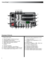
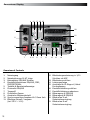
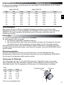
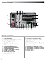
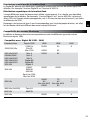
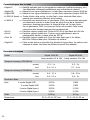
USER MANUAL GEBRAUCHSANLEITUNG MANUEL D’UTILISATION EN DE FR Digital 1200 RX 230V – 10256 110V – 10255 Digital 2400 RX 230V – 10258 110V – 10257 Elinchrom S.A Digital RX 01.02.2011 ENG (73256) Printed in Switzerland Table of contents Introduction 3 Declaration of conformity, disposal and recycling, CE marking 4 Safety notice and precaution 4 Before you start 5 Control Panel 6 Functions 7, 8 fuses 9 Flashheads 10 Flashheads compatibility 11 Flashheads Technical Data 12 Wireless Remote Control and Flash Triggering Troubleshooting 13 Guarantee 39 P.S: Technical data subject to change. The listed values are guide values which may vary due to tolerances in components used. 2 Introduction The Elinchrom Digital RX is manufactured by Elinchrom S.A. CH -1020 Renens/Switzerland Dear Photographer, Thank you for buying your Digital RX flash generator. All Elinchrom products are manufactured using the most advanced technology. Carefully selected components are used to ensure the highest quality and the equipment is submitted to many controls both during and after manufacture. We trust that it will give you many years of reliable EN service. All Digital RX flash units are manufactured for the studio and location use of professional photographers. Only by observance of the information given, can you secure your warranty, prevent possible damage and increase the life of this equipment. Digital RX Flash Generator The quality of light and exceptional performance is the result of long research, application of demanding principles, the long experience of ELINCHROM in lighting products for the studio and the utilization of the latest technology in this area. Totally integrated to the range of the ELINCHROM flashes, the Digital RX Flash generator maintain the traditional look and function that is ELINCHROM. FCC Class B Compliance Statement Note: This equipement has been tested and found to comply with the limits for a class B digital device, pursuant to Part 15 of the FCC Rules and meets all requirements of the Canadian Interference-Causing Equipement Regulations. These limits are designed to provide reasonable protection against harmful interference in a residential installation. This equipement generates, uses, and can radiate radio frequency energy and, if not installed and used in accordance with the instruction manual, may cause harmful interference to radio communications. However, there is no guarantee that interference will not occur in a particular installation. If this equipement does not cause harmful interferences to radio or television reception, which can be determined by turning the equipement off and on, the user is encouraged to correct the interferences by one or more of the following measures: - Reorient or relocate the receiving antenna. - Increase the separation between the equipement and receiver. - Connect the equipement into an outlet on a circuit different from that to which the receiver is connected. - Consult the dealer or an experienced radio/TV technician for help. Elinchrom S.A. is not responsible for any radio or television interference caused by unauthorised modifications of this equipement or the substitution or attachment of connecting cables and equipement other than those specified by Elinchrom S.A. The correction of interference caused by such unauthorised modification, substitution or attachment will be the responsibility of the user. 3 Declaration of conformity This device complies with Part 15 of the FCC Rules. Operation is subject to the following two conditions: 1. This device may not cause harmful interference. 2. This device must accept any interference received, including interference that may cause undesired operation. Product name: Professional Studio Flash Generator Trade name: ELINCHROM Model number(s): Digital RX Name of responsible party: Elinchrom S.A Av. De Longemalle 11 1020 Renens / Switzerland Phone : +41 21 637 26 77 Fax: +41 21 637 26 81 We, Elinchrom S.A., hereby declare that the equipement bearing the trade name and model number specified above was tested conforming to the applicable FCC rules, and that all the necessary steps have been taken and are in force to assure that the production units of the same equipement will continue to comply with the Comissions requirements. Disposal and recycling This device has been manufactured to the highest possible degree from materials which can be recycled or disposed of in a manner that is not enviromentally damaging. The device may be taken back after use to be recycled, provided that is returned in a condition that is the result of normal use. Any components not reclaimed will be disposed of in a environmentally acceptable manner. If you have any question on disposal, please contact your local office or your local ELINCHROM agent (check our website for a list of all ELINCHROM agents world wide). CE marking The shipped version of this device complies with the requirements of ECC directives 89/336/ECC «Electromagnetic compatibility» and 73/23/ECC «Low voltage directive». Notational Conventions The meaning of the symbols and fonts used in this manual are as follows: ! i Pay particular attention to text marked with this symbol. Failure to observe this warning endangers your life, destroys the device, or may damage other equipement Supplementary information, remarks, and tips follow this symbol. Text which follows this symbol describes activities that must be performed in the order shown. «Quotation marks» indicate names of chapters or terms 4 Before you start ! User Safety Information • Keep flash units out of reach whenever possible. • Switch off when not in use and disconnect flashheads. • Do not use in restricted areas (like hospitals, etc.) • Do not use near flammable/explosive material. • It must be protected from dripping water and from extremely dusty conditions • The unit must ALWAYS be plugged into an EARTHED electrical socket. • This equipment should be used only in a dry environment • If the unit has been exposed to very cold conditions, sudden exposure to warm or humid air may cause condensation => the unit should acclimate for some time to prevent condensation. • There is high voltage and can be high currents, so please apply all the usual safety precautions when handling the unit, changing fuses, modelling lamps etc. • Do not open the unit. In the event of damage or apparent failure, contact a repair service or any Elinchrom agent or email: [email protected] • Always switch off the unit before connecting or disconnecting flashheads • Check always if flashhead connections are plugged in and locked correctly EN Flash Tubes and Modelling lamps • Flash tubes and modelling lamps in use are very hot! • Never touch a flash tube or lamp before the unit cooled down and is disconnected from the mains. • Do not fire flashes from short distance (less than 1m) directed to a person and avoid looking into the flashlight! • Keep generally distance to operating units. ! • • • • • • • Always switch off the unit before connecting or disconnecting flashheads! The head connector must always be locked correctly before any use. Never store liquids or drinks on the power pack panel or closed to the unit! Flash systems store electrical energy in capacitors by applying high voltage. For your safety, never open or disassemble your flashes. Only an authorised service engineer should open or attempt to repair the units. Internal defect charge capacitors may explode whilst the unit is in use, neve switch on a not proper working flash unit. 5 Control Panel 4 16 17 18 19 20 1 21 2 15 3 10 7 9 11 6 5 8 12 13 14 Overview of Controls 1. 2. 3. 4. 5. 6. 7. 8. 9. 10. 11. 6 Mains inlet socket Fuse AC supply (16 AT, slow blow) Illuminated mains switch Modelling control (on/off free or prop) Open flash and charge indicator Slave cell on/off Handle Photocell receptor Acoustic recharging signal (Beep) Synchro-sockets, Amphenol + jack 3.5 mm Charge speed (slow charge 230 V = 10 A) 12. Decrease power adjustment in 1/10 f-stops, with ADF 13. Increase power adjustment in 1/10 f-stops 14. Power display 15. Socket for remote or USB - Multi Link 16. Increase modelling power 17. Decrease modelling power 18. Lamphead (on/off) outlet A 19. Lamphead (on/off) outlet B 20. Socket outlet A (with security catch) 21. Socket outlet B (with security catch) Operating Instructions Before connecting the digital RX for the first time, make sure that your mains supply and the rating set on the equipment (electrical specification plate) are compatible to 110V or 230V. • • • • • • • • Connect lampheads ensuring that lamphead touches (18-19) are Off. Connect the mains cord in the inlet socket (1) Select charging rate (11) (" " slow position), only when the mains supply is too limited. Select modelling lamp setting (4) Connect the synchro lead (10) Check that the photocell’s switch (6) is in the required position. Use the touch buttons (12 - 13) to select the desired power. The open flash (5) will light up, indicating that the unit is ready for operation. EN Fonctions On/Off Switch (1) By pressing this touch button the Digital RX is switched on or off. This unit is protected by a thermal circuit breaker to avoid overheating. Should this occur, the unit turns off automatically and cannot be operated! After a break for cooling, the flash is ready again for operation. Digital Power Display (14) The actual flash power is displayed in a f-stop compatible format. The power range is 6 f-stops. The digital display, provides continuous power indication of the flash and modelling lamp. The controls cover a continuous output range from full power 1/1 to 1/32th in 1/10th f-stop steps. During charging or discharging the display "flashes". In case of overheating or malfunction, the display shows "ER" for error. Digital Power Regulation (12 and 13) The power control provides simultaneous and continuously variable adjustment of the modelling lamp and the flash power in step of 1/10 f-stop. The display, provides digital power information, in f-stop from 3.5 to 8.5 for the "Digital 2400 RX" and 2.5 to 7.5 for the "Digital 1200 RX". Modelling Lamp Controls (4-16-17) • Proportional: The modelling lamp will be adjusted automatically in proportion, when the flash power is set to another value with touch button 12 or 13. • Free: To set flash- and modelling lamp values individually. • Modelling Lamp off Note: There is an additional ON/OFF switch for the modelling lamp at the flashhead! The flashhead control button A/B must be switched on for the selected flashhead. 7 Slow Charge (3) The green LED indicates that the slow charge function is selected. This position is recommended if the mains line capacity is limited for the standard fastcharge mode. Open Flash (5) When the green LED is illuminated the flash may be released manually. The release is blocked during charging, but not when the unit discharges. The integrated discharge system is protected by a thermic cut out. In order to restrict the heating of the unit, we suggest to release a flash with the green touch (5) "READY" after each strong reduction of power (more the 2f-stop). This allows to release the excess of energy in the flash tube. You will gain time and extend the life span of your power packs. Photocell On/Off (6) The Photocell (8) is activated when the green LED (4) is illuminated. When switched on, the pack can be remotely triggered by another flash unit! The Digital RX photocell is specially designed to work under ambiant light situation in your studio, direct light or other strong lights may reduce the sensitivity of the cell. In difficult situations e.g. blinding, sunlight or obstacles, the additional cell with 5 m cord (extensions available) solves most problems. Charge Ready Beep (9) Press this touch (9) to activate the acoustic signal Once recycled, an acoustic signal (beep) indicates that the power pack is ready. Synchronisation Socket Standard / Elinchrom Amphenol socket or 3.5 mm mini-jack (10). N.B. Do not link ELINCHROM power packs via sync cable to other brands. ELINCHROM uses low voltage (5V) for security reasons. Other systems may have higher voltages and could cause damages. Flashheads Control button These buttons switches on the flashhead sockets. 8 Relation of power range between the outlets Guide aperture is based on the " Digital S or Digital SE " lamphead and the 50° reflector, distance 1 m/3.3 ft and film ISO 100/21 DIN. Digital 1200 RX Digital 2400 RX Scale Ws f-stop Scale Ws f-stop Power 7.5 1200 (128) 8.5 2400 (180) 1/1 6.5 600 (90) 7.5 1200 (128) 1/2 5.5 300 (64) 6.5 600 (90) 1/4 4.5 150 (45) 5.5 300 (64) 1/8 3.5 75 (32) 4.5 150 (45) 1/16 2.5 37.5 (22) 3.5 75 (32) 1/32 EN Main Supply While the MAINS SWITCH (3) is switched OFF (not illuminated), firmly push in the plug of the original ELINCHROM mains cord (1). Fuse Standard type 5 x 20 mm, 16 AT (tempered). Before exchanging a blown fuse, switch off the unit and remove mains cable. Depress and turn the fuse holder anti-clockwise 1/8th and remove it. If the new fuse blows immediately upon reconnection return the pack to an ELINCHROM service centre for a check-up. (N.B. Check correct value of the fuse: 16 AT). Overvoltage security This unit is protected by security device. Should the unit not work properly, due to a defective power component, the security would instantly stop the charge. The power pack requires a check up at a technical Elinchrom service. Fuses for flashheads Use only FAST BLOW FUSES, type 5 x 20 mm corresponding to the label on each flashhead. Different modelling lamps require corresponding fuses. Slow blow fuses will not protect the modelling lamp. The fast blow fuse will protect the triac of the modelling lamp circuit, the lamp and therefore the flash tube. Fuse W 110V 240V 200 2 AF 2 AF 250 5 AF 2.5 AF 300 5 AF 2.5 AF 650 10 AF 5 AF Modelling Lamp switch Fuse Only use recommended fuse 9 Flashheads When plugging in a lamphead connector, first push in the front part, then firmly press in the whole plug, the rear part being secured by the locking spring. 2 ! Do NOT plug in or unplug lampcords while the green leds on output A and B are ON (illuminated) 1 Socket Halogen modelling lamp Use only the recommended modelling lamp, the Digital S and Digital SE heads are fitted with a 300 W halogen modelling lamp. For 230 V code 23022. Protective Pyrex Dome For use with standard halogen lamp GX 6.35 socket. Transparent, matt or yellow (400° K colour correction), can be fitted to all lampheads, except R heads for which clear or matt security filters are available. Easy attachment of the protective dome: • Disconnect the lamphead from the pack • Loosen the 3 screws of the lamphead reflector • Fit the clips underneath the screw heads and tighten the screws • Put the dome in place and hook the springs into the airvent holes. Protective dome Safety Precautions ! 10 • The flashheads cannot be insulated against humidity and dust. • Do NOT plug in or unplug lampcords while the green leds on output A and B are ON (illuminated). • Never store liquids or drinks on the power pack panel or closed to the unit! • Do not use near flammable/explosive material (min. 1m distance of any object) • For your safety, use only Elinchrom flashheads. • Do not open the unit. In the event of damage or apparent failure, contact a repair service or any Elinchrom agent or email: [email protected] Symmetrical power distribution The Digital RX power packs deliver symmetrical power distribution when the same type of flashhead is used for both power pack outlets. For example 2x Digital S or 2x A 3000 N head. Asymmetrical power distribution It is possible to set asymmetrical power distribution by using two different heads like 1x Digital S and 1x A3000N head. Instead of a 50% - 50% split, this head combination splits into 75% for the A-head and 25% for the S-head. This is 1,5 f-stops more flash power for this A-head. Note: The A-heads are used for action freezing photography; therefore the flash tube is made differently to any other EL-flashhead. A-tubes draw power very rapidly, with the effect that 25% power is left for the S-head types. EN Flashhead Compatibilty Below is a table, listing lampheads made since 1980, which are adaptable and indicating the equivalent in the current series. Compatible with: Digital RX 1200 - 2400 Maximum Power From 1992 1988 1986 1980 1500/2000 Ws S1500 N Chic S2 Mini 1500 S2000 S2 S A2000 A2 2400 Ws/2000* 2400Ws/2000* 2400 Ws/2000* 2400 Ws/2000* 2400 Ws/2000* 3000 Ws Mini A Mini R Mini S Digital SE Digital RE Digital S R2000 R2 R3000 S3000N A3000N Spot Lite 3000 Box Lite 3000 S3000 A3000 S4000 A4 Box Lite 4000 R4000 T4 A4 Box Lite 4000 R4 T A X8000 X8 X 3000 Ws 4000 Ws 4800 Ws (2x2400) Twin X4 6000 Ws X6000N 8000 Ws 11 Flashead Types • Digital S => Ultimate stability for digital and multishot imaging. The heavy duty electrodes resist heat stress. • Digital SE => Suitable for universal use and standard multishot imaging. The flash tube can be used up to 3000 ws • Digital SEE => This head covers all universal studio us and comes with a long life Swiss Made flash tube up to 2400 ws. • A 3000 N Speed => Unique super short flash duration with a single, twin electrode flash tube to ensure even light distribution. • X 6000 N => The flat twin interlocking flash tubes bring a focusable light source to high power users. Cabled into a single 6000 ws power source the flash duration is halved. Cabled into 2x 3000 ws power packs faster discharges may be cycled quicker. • Mini S => Priced to budget with 250 w modelling lamp and a 2400 ws flash tube. • Mini A => Priced to budget for action freezing purposes with 250 w modelling lamp. • Twin X4 => Priced to budget with 2x U-type flash tubes, 2x cables up to 2400 ws for light banks and softboxes • Digital R => This linear flashhead creates sharp linear shadows and spreads light evenly. The integral support can fit filters and barndoors. Technical Data Units Digital 1200 RX Digital 2400 RX f-stop variation 22 to 128 f-stop variation 32 to 180 Charge Speed (mains 230V/60Hz) normal 0.3 - 1 s 0.5 - 2 s 0.4 - 2.1 s 0.7 - 3.4 s normal 0.6 - 1.7 s 0.6 - 3.8 s slow 0.6 - 2.2 s 0.8 - 5 s slow Charge Speed (mains 115V/60Hz) Flash Duration With Weight Dimensions 12 1 flashhead Digital S/SE 1/1200 1/600 2 flashheads Digital S/SE 1/1900 1/950 1 flashhead Digital type A 1/2200 1/1100 2 flashheads Digital type A 1/3400 1/1700 4.45 kg 6.5 kg 21.5 x 13.5 x 23.3 cm 21.5 x 13.5 x 32 cm Wireless Remote Control and Flash Triggering The charge socket is as well the interface for the EL-Skyport Trigger and Remote System. With the EL-Skyport RX Trigger Set 19358, the Digital RX can be triggered wireless, up to approximatly 100 m distance. Apart from triggering, the Transmitter offers modelling lamp on/off settings and flash power control in 1/10th steps. EN By using the EL-Skyport Computer Remote / Trigger Set 19359, all Digital RX functions can be controlled and operated with a Mac° or Windows° computer. For details of the most advanced wireless system please visit : www.elinchrom.com/products/RX Multi Remote/EL-Skyport Troubleshooting 1. The mains switch (3) is ON, but not illuminated • switch OFF the unit and change the mains fuse (2) • Use only time-lag fuse (16 AT), corresponding to the Digital RX pack 2. The switch (3) is lit, the green led of the open flash (5) is illuminated and the touch A or B (18 - 19) is activated but does not flash • the flashtube in the flashhead may be faulty • If replacing the lamphead does not solve the problem, the cause could be a component failure => please return the unit to an authorised Elinchrom service. 3. The ON/OFF switch (3) is lit but the open flash signal (5) is not lit • Temporary break for overheating, caused by fast flash sequences or ventilation slots obturated • Fan cooling defective => the unit turns off automatically and cannot be fired any more. After a break for cooling, the flash is ready again for operation. • If after several minutes of break for cooling the ready signal (5) is not lit, the cause could be a component failure. However, high voltage may remain on the capacitor circuits. ! • For your safety, never open your power pack. • Do not attempt to repair the unit yourself. • Please send the unit to your elinchrom agent 13 Inhalt Einleitung 15 CE Konformitätserklärung / Entsorgung 16 Vor dem Start /Sicherheits- und Gebrauchshinweise 17 Digitales Display / Anschlüsse 18 Funktionen 19 Blitzleistungsanzeige des Displays 20 Stromanschluss / Sicherungen 21 Blitzköpfe / Leistungsverteilung 22 Kompatible Blitzköpfe 23 Technische Daten 24 Synchronisation, Funkfernauslösung 25 Elinchrom Zubehör 38 Garantie 39 VERMERK: Toleranzen der technischen Daten für Bauelemente und Messwerte entsprechen den IEC und EC Normen. Technische Änderungen vorbehalten. Die Werte können durch Bauelemente Toleranzen schwanken und sind als Richtwerte zu verstehen und nicht im rechtlichen Sinne als zugesicherte Eigenschaften. Keine Haftung für Druckfehler. 14 Einleitung Lieber Photograph, Die hervorragende Lichtqualität und die technische Leistung der Digital RX 1200/ 2400 Blitzgeneratoren beruhen auf einer 45 jährigen Erfahrung auf dem Gebiet der Blitzelektronik und der Herstellung von Blitzanlagen. Elinchrom Blitzlichtprodukte entsprechen den gültigen elektrischen Normen. DE ELINCHROM verwendet für seine Produkte nur hochwertige und geprüfte Baukomponenten. Auch während der Produktion unterliegen alle Geräte einer strengen Kontrolle. Die Endkontrolle sichert die Einhaltung des Qualitätsstandards und garantiert eine einwandfreie Funktion. Wir hoffen, dass Sie mit diesem Gerät sehr zufrieden sein werden. Um einwandfreie Ergebnisse zu bekommen und die zuverlässige Funktion für lange Zeit zu sichern, sind nachstehende Gebrauchsanweisungen und Vorsichtsmaßnahmen zu befolgen. Digital RX 1200/ 2400 Blitzgeneratoren werde von ELINCA S.A. Renens / Schweiz hergestellt. Wir danken Ihnen für Ihr Vertrauen. FCC Class B Compliance Statement Note: This equipement has been tested and found to comply with the limits for a class B digital device, pursuant to Part 15 of the FCC Rules and meets all requirements of the Canadian Interference-Causing Equipement Regulations. These limits are designed to provide reasonable protection against harmful interference in a residential installation. This equipement generates, uses, and can radiate radio frequency energy and, if not installed and used in accordance with the instruction manual, may cause harmful interference to radio communications. However, there is no guarantee that interference will not occur in a particular installation. If this equipement does not cause harmful interferences to radio or television reception, which can be determined by turning the equipement off and on, the user is encouraged to correct the interferences by one or more of the following measures: - Reorient or relocate the receiving antenna. - Increase the separation between the equipement and receiver. - Connect the equipement into an outlet on a circuit different from that to which the receiver is connected. - Consult the dealer or an experienced radio/TV technician for help. Elinchrom S.A. is not responsible for any radio or television interference caused by unauthorised modifications of this equipement or the substitution or attachment of connecting cables and equipement other than those specified by Elinchrom S.A. The correction of interference caused by such unauthorised modification, substitution or attachment will be the responsibility of the user. 15 Konformitätserklärung Dieses Gerät entspricht Paragraph 15 der FCC Normen, die folgende Punkte beinhalten: 1 Dieses Gerät verursacht keine Interferenzen die nicht den Normen entsprechen. 2 Dieses Gerät akzeptiert jegliche Interferenzen, auch die, die eventuell Störungen verursachen können. Produktname: Professionelles Studioblitzgerät Marktname: ELINCHROM Modellnummer(n): Digital RX Verantwortliche Firma: Elinchrom S.A Av. De Longemalle 11 1020 Renens / Switzerland Phone : +41 21 637 26 77 Fax: +41 21 637 2681 ELINCHROM S.A. erklärt hiermit unter seinem Marktnamen, dass die Geräte mit den genannten Modellnummern nach den einschlägigen EWG, DIN, IEC und FCC Normen geprüft und getestet wurden und allen Vorschriften entsprechen. Alle notwendigen Prüfungen werden durchgeführt um die Einhaltung und Sicherheit auch während der Serienproduktion zu garantieren. Entsorgung und Recycling Dieses Gerät wurde weitestgehend aus Materialien hergestellt, die umweltschonend entsorgt und einem fachgerechten Recycling zugeführt werden können. Nach seinem Gebrauch wird das Gerät zurückgenommen, um es einer Wiederverwendung bzw. wertstofflichen Verwertung zuzuführen, soweit es in einem Zustand zurückgegeben wird, der dem bestimmungsgemäßen Gebrauch entspricht. Nicht verwertbare Geräteteile werden sachgemäß entsorgt. Dieses Studioblitzgerät entspricht den Anforderungen der EWG Richtlinie 89/336/EWG Elektromagnetische Verträglichkeit” und 73/23/EWG “Niederspannungsrichtlinie”. Zeichenerklärung 16 ! In diesem Handbuch werden folgende Darstellungsmittel verwendet. kennzeichnet Hinweise, bei deren Nichtbeachtung Ihre Gesundheit, die Funktionsfähigkeit Ihres Gerätes oder die Sicherheit Ihrer Daten gefährdet. i Dieses Zeichen kennzeichnet zusätzliche Informationen bzw. Tipps. “Anführungszeichen” kennzeichnen Kapitelnamen und Begriffe, die hervorgehoben werden sollen. Kursive Schrift kennzeichnet Bedienelemente, Baugruppen oder Menüpunkte. Hinweise zur Sicherheit und Gebrauch vor dem Start • Seien Sie sich bewusst welche Gefahren und Unannehmlichkeiten es Personen und Kindern bereiten kann. • Lassen Sie niemals Kinder unbeaufsichtigt mit Blitzanlagen allein!! • Der Stromkreis, Steckdose an dem der Generator angeschlossen wird muss geerdet sein! • Wenn das Gerät starken Temperaturschwankungen ausgesetzt war, muss es akklimatisieren bevor es eingeschaltet wird. • Dieses Gerät nicht in verbotenen oder explosiven Bereichen verwenden. • Blitzanlagen nur mit Genehmigung der Zuständigen, in Krankenhäusern, Museen, Fabriken, DE etc. verwenden. • Halten Sie brennbare / explosive Materialien vom Generator und vom Blitzkopf fern! • Digital RX Generatoren wurden für den internen Studioeinsatz entwickelt und dürfen nur in trockener Umgebung verwendet werden. • Darauf achten das keine Getränke auf dem Gerät abgestellt werden oder Flüssigkeiten in das Gerät eindringen. • Generatoren die nicht im Gebrauch sind, ausschalten und Netzkabel und Blitzköpfe entfernen. • Immer erst den Generator abschalten bevor Blitzlampen angeschlossen oder entfernt werden. • Blitzkopfanschlüsse fest mit dem Generator verbinden und einrasten, erst dann den Generator einschalten. • Achtung Hochspannung, Stromschlaggefahr!! • Berühren Sie niemals die Blitzbuchsen / Kontakte mit den Fingern oder Werkzeugen! • Öffnen Sie niemals das Generatorgehäuse um Reparaturen oder Modifikationen durchzuführen! • Gefährliche elektrische Restspannungen haben u. U. gravierende Konsequenzen. • Nur der Elinchrom Service ist autorisiert, Arbeiten im und am Generator durchzuführen. Blitzköpfe, Blitzröhren und Pilotlicht • Blitzröhren und Pilotlicht werden bei Gebrauch sehr heiß. • Schauen Sie niemals direkt in das Blitzlicht! • Der Blitzkopf muss vom Generator getrennt werden und abkühlen, bevor eine Sicherung / Halogenlampe gewechselt wird. • Niemals Blitze aus geringem Abstand auf Personen auslösen. Der Mindestabstand sollte ca. 2 m betragen, abhängig von der eingestellten Blitzleistung. • Grundsätzlich Abstand zu anderen elektronischen Geräten halten die in Funktion sind. ! Zu Ihrer Sicherheit! Immer erst den Generator abschalten bevor Blitzlampen angeschlossen oder entfernt werden. Niemals Generatoren öffnen! Geladene Nur autorisierte Elinchrom Kundendienste dürfen das Gerät öffnen, reparieren oder Blitzröhren wechseln. Defekte interne Kondensatoren können mit einem lauten Knall explodieren! 17 Generatoren Display 4 16 17 18 19 20 1 21 2 15 3 10 7 9 11 6 5 8 12 13 14 Overview of Controls 1.Netzeingang 2. Netzabsicherung 16 AT, träge 3. Beleuchteter EIN/AUS Schalter 4. Einstelllichtfunktionen EIN/AUS, FREI, PROPORTIONAL 5. Testblitz & Bereitschaftsanzeige 6. Photozelle EIN/AUS 7.Tragegriff 8. Photozellen Sensor 9. Akustische Blitzbereitschaft 10. Synchronanschluss Amphenol & 3.5mm Jack 11. Blitzfolge Schnell / Langsam (bei 230 V – 10 A) 18 12. Blitzleistungsreduzierung in 1/10 Schritten mit ADF 13. Blitzleistung erhöhen 14.Leistungsanzeige 15. Anschluss für EL-Skyport / Kabel Fernbedienung 16. Einstelllichtleistung erhöhen 17. Einstelllichtleistung reduzieren 18. Blitzausgang A EIN/AUS 19. Blitzausgang B EIN/AUS 20. Blitzbuchse A mit Sicherheitsverrieglung 21. Blitzbuchse B mit Sicherheitsverrieglung Inbetriebnahme Vor dem ersten einschalten darauf achten das die Stromversorgung 110 V oder 230 V mit der Gerätebetriebsspannung übereinstimmt. Information darüber finden Sie auf dem Datenaufkleber an der Unterseite des Gerätes. • Ein/Aus Schalter muss auf Position AUS stehen. • Einen Blitzkopf anschließen und den Blitzlampenstecker fest verriegeln. Der Stecker muss einrasten. • Das Synchronkabel oder die EL Skyport Funkauslösung mit Generator und Kamera verbinden. • Alle Verbindungen nochmals prüfen. DE • Netzkabel anschließen und dann das Gerät einschalten, der Digital RX ist jetzt betriebsbereit. Funktionen EIN / AUS Schalter (beleuchtet) Leistungsanzeige Digitale Anzeige der Leistungseinstellung in blendenähnlichen Leistungsschritten. 6 Blendenwerte sind einstellbar, von 3.5 bis 8.5 für den Digital RX 2400 und 2.5 bis 7.5 bei dem Digital RX 1200 in 1/10 Blendenstufen. Wenn der Generator lädt oder entladen wird, blinkt diese Anzeige. Falls das Gerät überhitzt, oder Fehlerhaft ist, erscheint „ER“ für ERROR / FEHLER in der Anzeige. Taster für die Blitzleistungseinstellung Kontinuierliche Leistungseinstellung in 1/10 Leistungsschritten von 1/32 bis 1/1 in 1/10 Blendenstufen. Automatische Leistungsanpassung, wen die Blitzleistung reduziert wird. Pilotlichtfunktionen • Proportional / PROP: Das Einstellich passt sich in Proportion zur Blitzleistung an. • Frei / FREE: Individuelle Einstellung von Blitz- und Einstelllicht • Einstelllicht AUS Zusätzlich kann das Einstelllicht am Blitzkopf direkt EIN /AUS geschaltet werden. Die Blitzkopftaster an den Blitzkopfanschlüssen A / B müssen eingeschaltet werden um den Blitzkopf zu aktivieren. 19 Langsam Ladung: Diese Einstellung empfiehlt sich wenn die Stromversorgung nicht ausreichend ist, oder mehrere Generatoren im Studio betrieben werden. Test Blitz Mit diesem Taster kann ein Blitz manuell Ausgelöst werden. Während der Aufladung ist der Taster gesperrt, wird die Leistung reduziert, kann auch manuell die Leistung abgeblitzt werden, was sich empfiehlt bei Reduzierungen über 2 Blendenwerten um die Entladeelektronik nicht zu überhitzen. Photozelle EIN /AUS Bei eingeschalteter Photozelle blitzt der Generator simultan sobald ein Blitzimpuls registriert wird. Die Empfindlichkeit der Photozelle ist auf Studiobetrieb abgestimmt. Vermeiden Sie grelles Einstelllicht oder direkte Sonne auf den Photozellen Sensor, was die Empfindlichkeit reduzieren kann. Akustische Ladebereitschaft Wenn diese Funktion eingeschaltet ist, erscheint ein BEEP-Ton nach dem Ladevorgang und signalisiert die Blitzbereitschaft. Synchronisation Für die Synchronisation stehen 2 Synchronbuchsen mit Kameraschonender 5 V Synchronspannung zur Verfügung: • Elinchrom Standard Amphenol • 3.5 mm Mini Jack HINWEIS: Verbinden Sie niemals die Elinchrom Synchronbuchsen mit anderen Blitzfabrikaten. Spannungsunterschiede können defekte hervorrufen. Blitzausgangstaster Die Blitzausgangsbuchsen A und B können EIN / AUS geschaltet werden, was sowohl Blitz und Einstelllicht des Blitzkopfes abschaltet. 20 Relation zwischen Blitzleistungsanzeige und der Blitzleistung in Joule Die Blendenwerte basieren auf Messungen mit dem Digital S und SE Blitzkopf mit 50° Reflektor, 1 m Distanz und 100 ISO. Digital 1200 RX Digital 2400 RX Scale Ws f-stop Scale Ws f-stop Power 7.5 1200 (128) 8.5 2400 (180) 1/1 6.5 600 (90) 7.5 1200 (128) 1/2 5.5 300 (64) 6.5 600 (90) 1/4 4.5 150 (45) 5.5 300 (64) 1/8 3.5 75 (32) 4.5 150 (45) 1/16 2.5 37.5 (22) 3.5 75 (32) 1/32 DE Stromversorgung Bitte immer nur das von Elinchrom gelieferte Netzkabel verwenden und auf die richtige Netzspannung achten. Vor dem anschließen des Netzkabels, den Generator vorher abschalten! VORSICHT: Vor dem Einschalten die Blitzköpfe an den Generator anschließen und alle Verbindungen prüfen. Sicherungen Nur original Sicherungen 5 x 20 mm, 16 AT verwenden. Vor dem wechseln einer Sicherung; 1. den Generator abschalten, Netzkabel entfernen, 2. Den Sicherungshalter leicht nach unten drücken und gegen den Uhrzeigersinn mit einer 1/8 Umdrehung den Sicherungshalter herausschrauben und die Sicherung wechseln. Sollte die Sicherung sofort nach dem Einschalten wieder durchbrennen, überprüfen Sie ob die korrekte Sicherung verwendet wurde, sonst muss der Generator von einem ELINCHROM Service geprüft werden. Überspannungsschutz Sollte die Leistungselektronik nicht korrekt funktionieren, wird die Ladeelektronik der Kondensatoren unterbrochen. Der Generator muss dann von einem qualifizierten ELINCHROM Service geprüft und gegebenenfalls repariert werden. Sicherungen für Blitzköpfe Nur Sicherungen des Typs 5 x 20 mm FLINK verwenden. Träge Sicherungen verursachen unter umständen das, dass Einstelllicht explodiert und die Blitzröhre und der Lampen Triac beschädigt werden. Nur die angegebenen Sicherungen und Halogenlampen verwenden. Fuse W 110V 240V 200 2 AF 2 AF 250 5 AF 2.5 AF 300 5 AF 2.5 AF 650 10 AF 5 AF Only use recommended fuse Einstelllichtschalter Sicherung 21 Blitzköpfe Wenn Blitzköpfe angeschlossen werden... 1. Generator Abschalten 2. Erst den vorderen Teil des Blitzsteckers in die Blitzbuchse einführen 3. Dann den hinteren Teil des Blitzsteckers herunterdrücken, bis der Stecker einrastet. 4. Prüfen ob alle Verbindungen korrekt sind, dann den Generator einschalten. ! 2 1 Socket Halogen Einstelllicht Bitte nur die von Elinchrom verwendeten 300 W / GX 6.35 Halogenlampen in den 230 V oder 110 V Versionen verwenden! Auf die korrekte Absicherung achten. Schutzglasglocken Alle Blitzköpfe für Generatoren mit der Standard Halogenlampe GX 6.35 können mit Schutzglasglocken nachgerüstet werden. Folgende Versionen sind verfügbar: • Schutzglasglocke transparent-klar inkl. Befestigungsset // 24925 • Schutzglasglocke matt-gefrostet inkl. Befestigungsset // 24926 • Schutzglasglocke 400 Kelvin warm-ton inkl. Befestigungsset // 24927 Einfache Montage der Glasglocke • Blitzkopf vom Generator trennen Schutzglasglocken • die drei Schrauben des Innenreflektors lösen • die Befestigungsklipps unter die gelöste Innenreflektor Schraube schieben danach wieder fest verschrauben • die Glasglocke aufsetzen und die Federklipps mit den Lüftungslöchern des Schutzglases verbinden. Für Ihre Sicherheit ! 22 • Die Blitzköpfe müssen vor Feuchtigkeit und Staub geschützt werden! • Immer erst den Generator abschalten, bevor Blitzköpfe gewechselt / hinzugefügt werden! • Niemals Getränke etc. auf dem Generator abstellen!! • Blitzköpfe immer mit ausreichend Abstand zu brennbaren Materialien aufstellen! • Verwenden Sie nur original Elinchrom Blitzköpfe! Andere Hersteller verwenden die gleichen Blitzstecker, die aber anders Konfiguriert sind! ACHTUNG EXPLOSIONSGEFAHR!! • Niemals den Blitzkopf oder den Generator öffnen, nur dem Elinchrom Service ist dies gestattet. Symmetrische Blitzleistung Die Blitzleistung der Blitzausgangsbuchsen ist symmetrisch verteilt, wenn jeweils Blitzköpfe des gleichen Typs verwendet werden. Asymmetrische Blitzleistung Eine asymmetrische Leistungsverteilung ist dennoch möglich, wenn Beispielsweise zwei unterschiedliche Blitzköpfe verwendet werden, wie z.B. Digital S und der A 3000N Blitzkopf verwendet werden. Diese Kombination verteilt die Leistung auf ca. 75% für den A-Blitzkopf und 25% für den S-Blitzkopf, mit ca. 1.5 Blenden Leistungsunterschied. Bemerkung: A-Blitzköpfe sind mit einer speziellen Blitzröhre ausgestattet und reduzieren die Blitzdauer um Bewegungen einzufrieren. DE Blitzkopfkompatibilität In der Tabelle unten sind die Blitzköpfe aufgeführt, die Elinchrom seit ca. 1980 produziert hat und die mit Digital RX Generatoren kompatibel sind. Compatible with: Digital RX 1200 - 2400 Maximum Power From 1992 1988 1986 1980 1500/2000 Ws S1500 N Chic S2 Mini 1500 S2000 S2 S A2000 A2 2400 Ws/2000* 2400Ws/2000* 2400 Ws/2000* 2400 Ws/2000* 2400 Ws/2000* 3000 Ws Mini A Mini R Mini S Digital SE Digital RE Digital S R2000 R2 R3000 S3000N A3000N Spot Lite 3000 Box Lite 3000 S3000 A3000 S4000 A4 Box Lite 4000 R4000 T4 A4 Box Lite 4000 R4 T A X8000 X8 X 3000 Ws 4000 Ws 4800 Ws (2x2400) Twin X4 6000 Ws X6000N 8000 Ws Blitzkopfversionen • Digital S => Farb- und Blitzstabilität des Digital S entspricht den höchsten Standards für die digitale Photographie. Die bis 4000 J belastbare Röhre ermöglicht große Blitzserien. Hitze und sonstiger Dauerstress verarbeitet der Digital S souverän. Schutzglasglocken sind optional erhältlich. 23 • Digital SE • Digital SEE • A 3000 N Speed • X 6000 N • Mini A / Mini S • Twin X4 • Digital RE => Der Digital SE Blitzkopf ist für analoge und digitale Photographie bestens geeignet. Die Blitzröhre verträgt bis 3000 Joule. Schutzglasglocken sind optional erhältlich => Der preisgünstige Blitzkopf bewältigt universelle Aufgaben in der digitalen Photographie und kann bis maximal 2400 J belastet werden. Schutzglasglocken sind optional erhältlich. => Die feine schnelle Art! Eine Einzelblitzröhre mit einer DoppelElektrode halbiert die Blitzdauer. Perfekt um Bewegungen einzufrieren. Schutzglasglocken optional erhältlich => Die spezielle Doppel-Blitzröhre halbiert die Blitzdauer, wenn das Doppelkabel an einem Generator angeschlossen wird. Wird das Doppelkabel an zwei EL Generatoren 3000 J angeschlossen, sind maximal 6000 J Belastung möglich. Schutzglasglocken sind optional erhältlich => Die preiswerten Einsteiger Blitzköpfe mit Gebläsekühlung, Aluminium Gehäuse und E27 Lampensockel entsprechen den Elinchrom Standards. Blitzröhre, Blitzlampenkabel und Kühlgebläse sind identisch zu anderen Blitzköpfen. Der Mini A reduziert die Blitzdauer um ca. 45 % => Doppel-Kabel und Blitzröhren an einem Generator adaptiert, reduzieren die Blitzdauer um 50 %. Wird der Twin X 4 an zwei Generatoren angeschlossen, sind max. 4800 Joule möglich. Der preiswerte, mit U-Blitzröhren ausgestattete Twin X 4 erzielt gute Ergebnisse mit Softboxen und Lichtwannen. => Ideal für lineare Schattenbildung, oder verlaufende Hintergründe. Mit Mattfolien können große Flächen gleichmäßig beleuchtet werden. Exzellente Ergebnisse erzielt man bei Sonnenlichteffekten durch Fenster und Jalousien. Der Stativadapter mit integrierter Schirmhalterung ermöglicht eine präzise Ausrichtung Technische Daten Generatoren Digital 1200 RX Blende / 1m / ISO 100 / Reflector 48° 128 Digital 2400 RX 180 Blitzfolge / 230 V 0.3 - 1 s 0.5 - 2 s Langsam Schnell 0.4 - 2.1 s 0.7 - 3.4 s Schnell 0.6 - 1.7 s 0.6 - 3.8 s Langsam 0.6 - 2.2 s 0.8 - 5 s 1/1200 1/600 Blitzfolge / 115 V Blitzdauer Blitzdauer t 0.5 mit 1x Digital S / SE Blitzdauer t 0.5 mit 2x Digital S / SE 1/1900 1/950 Blitzdauer t 0.5 mit 1x A-Action Blitzk. 1/2200 1/1100 Blitzdauer t 0.5 mit 2x A-Action Blitzk. 1/3400 1/1700 4.45 kg 6.5 kg 21.5 x 13.5 x 23.3 cm 21.5 x 13.5 x 32 cm Gewicht Dimensionen * Ausführliche Technische Daten finden Sie im Elinchrom Systemkatalog und auf www.elinchrom.com. 24 EL-Skyport Fernbedienung und Auslösung Digital RX Generatoren verfügen seitlich über eine Einsteckbuchse für das EL-Skyport Tranceiver RX Empfängermodul. Mit dem EL-Skyport Set 19358 kann der Generator über den ELS Transmitter ausgelöst und in der Leistung verstellt werden. Mit dem EL-Skyport Computer Remote & Auslöse Set 19359 und der frei verfügbaren EL-Skyport Software können alle Funktionen mit dem Computer eingestellt werden. Aktuelle Informationen finden Sie unter www.elinchrom.com. DE Fehlerbehebung Der EIN / AUS Schalter ist eingeschaltet, aber leuchtet nicht: • Generator abschalten und die Netzsicherung austauschen. • Bitte nur Sicherungen des Typs 16 A T (Träge) verwenden. Der Generator ist eingeschaltet, die Blitzbereitschaft leuchtet und die A und B Blitzbuchsen sind eingeschaltet, aber der Blitz kann nicht ausgelöst werden: • Eventuell ist die Blitzröhre defekt. • Probieren Sie einen anderen Blitzkopf, sollte das Problem weiterhin bestehen, muss der Generator von einem Elinchrom Servicepartner kontrolliert werden. Der EIN / AUS Schalter leuchtet, aber die Blitzbereitschaft ist nicht aktiv: • Temporäre Unterbrechung bedingt durch Überhitzung, verursacht durch starke Benutzung oder eventuell ein defekter Lüfter. • Defektes Kühlgebläse; bei Überhitzung schaltet das Gerät ab, nach einer Abkühlphase, kann wieder mit dem Gerät gearbeitet werden. • Falls nach 10 – 15 Minuten das Gerät immer noch nicht funktioniert, liegt eventuell ein Komponentenfehler vor. Vorsicht, niemals das Gerät öffnen!! Lebensgefährliche Hochspannung kann in den Kondensatoren gespeichert sein. Nur dem Elinchrom Service Partner ist es gestattet Reparaturen vorzunehmen Spannungen! ! Zu Ihrer Sicherheit • Niemals den Generator öffnen, im Geräteinneren ist lebensgefährliche HOCHSPANNUNG • Falls das Gerät nicht einwandfrei funktioniert, sofort abschalten! • Defekte Kondensatoren können explodieren, was einen lauten Knall verursacht, zudem können geringfügig Chemikalien auslaufen! Sofort Jegliche Stromversorgung abschalten und eventuell mit Schutzhandschuhen den Generator in eine Plastikbox stellen. • Jegliche Reparaturen und sonstige Eingriffe sind nur dem Elinchrom Service Partnern gestattet. 25 Table of contents Introduction 27 Déclaration de conformité, recyclage, marquage CE 28 Notice de sécurité et précautions 29 Interface d’utilisation 30 Mise en marche 31 Fonctions 31 Relation de gamme de puissance entre les sorties 33 Fusibles 33 Torches 34 Distribution de la lumière flash 35 Caractéristiques des torches 36 Données techniques 36 Déclenchement sans fil (wireless) 37 Dépannage 37 Accessoires Elinchrom 38 Garantie 39 P.S: Les informations contenues dans ce manuel peuvent faire l’objet de modifications sans préavis. 26 Introduction Le Digital RX d’Elinchrom est fabriqué par Elinchrom S.A. à Renens / Suisse. Cher(s) photographe(s),Nous vous remercions de votre achat. Toute la gamme Elinchrom est fabriquée avec du matériel de très haute qualité et a subi de nombreux contrôles et essais pendant et après le processus de fabrication. Nous espérons qu’il vous donnera entière satisfaction. Vous obtiendrez les meilleurs résultats en suivant nos conseils de prudence et d’utilisation. FR Générateur Digital RX La qualité de la lumière et les performances exceptionnelles sont le résultat de recherches poussées dans la physique du flash, de l’application de principes éprouvés, de l’expérience ELINCHROM dans le domaine de l’éclairage de studio et de l’utilisation de composants issus des dernières technologies. Totalement intégré à la vaste gamme des flashes ELINCHROM, le Digital RX hérite des principales fonctionnalités et caractéristiques des produits ayant fait la réputation de la marque ELINCHROM. FCC Class B Compliance Statement Note: Cet équipement a fait l’objet de tests et a été déclaré conforme aux limites auxquelles sont soumis les appareils numériques de la Classe B, conformément à la section 15 de la réglementation FCC, il n’émet pas de bruits radioélectriques dépassant les limites prescrites dans le règlement sur le brouillage édicté par le ministère des communications du Canada. Ces limites ont été fixées afin d’apporter une protection raisonnable contre les perturbations pouvant survenir sur une installation domestique. Cet équipement, peut émettre de l’énergie de fréquences radio et pourrait, s’il n’est pas installé et utilisé en conformité avec les instructions, perturber la réception des ondes radio. Cependant, il n’est pas garanti qu’une installation domestique ne sera pas dérangée par des interférences. Si cet équipement provoque des interférences lors de réception d’ondes radio/TV, vérifiable en mettant l’équipement hors tension puis sous tension, l’utilisateur est invité à prendre une ou plusieurs des mesures suivantes pour tenter de supprimer cet inconvénient : • Réorienter ou déplacer l’antenne réceptrice de la radio/TV. • Augmenter la distance qui sépare l’équipement perturbateur du récepteur radio/TV. • Brancher l’équipement dans une prise de courant d’un circuit différent de celui sur lequel le récepteur est raccordé. • Demander l’aide du revendeur ou d’un technicien expérimenté en radio/ TV. Elinchrom S.A ne peut être tenu pour responsable des perturbations radioélectriques, du remplacement ou du branchement de câbles de raccordement et d’équipements autres que ceux qui sont mentionnés et fournis par Elinchrom S.A. La substitution ou un raccordement non autorisé relèvera de la seule responsabilité de l’utilisateur. 27 Déclaration de conformité Cet appareil est conforme aux règles FCC, paragraphe 15. Son exploitation est soumise aux deux conditions suivantes: 1. Cet appareil ne doit pas provoquer d’interférences nuisibles. 2. Cet appareil doit supporter les interférences extérieures, notamment celles susceptibles d’engendrer un dysfonctionnement. Nom du produit : Digital studio unit Marque : ELINCHROM Référence : Digital RX Responsable : Elinchrom S.A Av. De Longemalle 11 1020 Renens / Switzerland Téléphone : +41 21 637 26 77 Fax: +41 21 637 2681 Nous, Elinchrom S.A, certifions par la présente que l’équipement de marque et de référence telles que spécifiées ci-dessus a été testé conformément aux règles FCC en vigueur, selon les normes et mesures précises et que toutes les démarches nécessaires ont été effectuées et sont mises en œuvre pour garantir que l’unité de production de ce produit continuera à satisfaire les exigences requises. Elimination et recyclage Ce symbole apposé sur le produit ou sur son emballage, indique que ce produit ne doit pas être jeté avec les déchets ménagers ordinaires. Cet appareil a été presque entièrement fabriqué à partir de matériaux dont l’élimination est respectueuse de l’environnement et dont le recyclage peut être assuré de manière appropriée. En fin de vie, l’appareil sera remis dans un centre de collecte et de tris de déchets électriques ou repris par le fabricant qui le recyclera ou en récupérera les matières premières. Les composants non récupérables seront éliminés en bonne et due forme de la manière la plus appropriée. Marquage CE La version de ce flash est conforme aux spécifications et exigences des directives CEE 89/336/EEC “Compatibilité électromagnétique” et 73/23/EEC “Directives basse tension”. Symboles Les symboles suivants sont utilisés dans ce manuel : ! i 28 Signale les instructions à respecter impérativement pour une utilisation sans risque des unités autonomes “Digital RX”. Votre sécurité et celle de votre appareil sont en jeu! Précède des informations et des conseils complémentaires. “Entre guillemets” sert à identifier ou mettre en évidence des titres, des repères, abréviations et concepts. Avant de commencer! • Les flashes doivent être hors de portée des enfants et des personnes non familières à cet équipement. • Eteindre le générateur lorsqu’il est inutilisé, débrancher les lampes (torches) et remettre les bouchons de protection. • Ne pas utiliser en zone restreinte (hôpital, etc.) • Ne pas utiliser en zone inflammable ou à risque d’explosion. • Dans des conditions humides, protéger votre générateur et vos torches! • Le Digital RX doit toujours être raccordé à la terre. • Eviter les problèmes de condensation. • L’unité contient de la haute tension, prenez donc vos précautions lorsque vous changez fusibles, ampoules, etc. • Ne jamais ouvrir l’appareil! En cas de problèmes, apporter votre Ranger RX à votre revendeur Elinchrom. • Le Digital RX doit toujours être éteint lors de changement de torches. • Controler que les torches soient correctement connectées au générateur. FR Tube flash et lampe pilote • Le tube flash et l’ampoule sont brûlants! • Déconnecter le flash du secteur et attendre quelques minutes avant de remplacer le tube flash. • Ne pas déclencher le flash si une personne se trouve à moins d’un mètre de la torche. • Ne pas utiliser ce flash à proximité de matériaux ou produits inflammables. ! • Le Digital RX doit toujours être éteint lors de changement de torches! • Les torches doivent être correctement connectées au générateur, le système de fixation à bayonnettes doit être bien verrouillé! • Les boissons ou tout autre liquide, ne doivent en aucun cas être entreposés à proximité de l’unité. • De la haute tension est stockée dans les condensateurs du Digital RX. • Seul un technicien Elinchrom est autorisé à ouvrir l’appareil. • En cas de problèmes, prenez contact avec l’agent Elinchrom de votre pays. • Le Digital RX doit être hors de portée des enfants et des personnes non formée à son utilisation. 29 Interface d’utilisation 4 16 17 18 19 20 1 21 2 15 3 10 7 9 11 6 5 8 12 13 14 Eléments de commande 1. 2. 3. 4. Prise d’alimentation Fusible principal 16 AT (fusion retardée) Interrupteur principal lumineux Sélecteur d’éclairage pilote (on/off free or prop) 5. Déclenchement manuel et témoin de fin de charge 6. Cellule photoéléctrique on/off 7. Poignée de transport escamotable 8. Cellule photoélectrique 9. Indicateur sonore de fin de charge 10. Prise de synchronisation 11. Sélecteur de charge lente (pour installation 10 A) 30 12. Diminution de puissance du flash 13. Augmentation de puissance du flash (6 diaph.) 14. Affichage digital 15. Prise de contrôle à distance (EL-skyport) 16. Augmentation de puissance de la pilote 17. Diminution de puissance de la pilote 18. Touche de mise en service de la sortie A 19. Touche de mise en service de la sortie B 20. Sortie de torche A 21. Sortie de torche B Mise en marche Avant de raccorder le générateur au réseau, vérifiez que la prise soit pourvue d’un contact de terre et que le voltage de votre réseau soit identique à celui inscrit sur l’étiquette d’identification, qui est située sur la plaque de fond du générateur. Assurez-vous que les fusibles qui protègent votre réseau de distribution aient un ampérage suffisant (minimum 16A). • Brancher le cordon secteur sur le générateur et ensuite au réseau. • Raccorder les torches, en s’assurant que l’interrupteur (3) est sur ”OFF”. • Enclencher le générateur au moyen de l’interrupteur (3). • Raccorder le cordon de synchronisation sur l’une des prises (10). • Si vous utilisez plusieurs générateurs ou plusieurs unités, contrôler que la cellule (6) soit sur FR ”ON”. • Enclencher les sorties flashes et pilotes en appuyant sur les touches A et/ou B (18 et 19). • L’indicateur de charge (5) s’illuminera. Votre Digital RX est prêt à l’emploi. Fonctions Interrupteur principal (3) Le générateur est sous tension lorsque le voyant rouge est illuminé. Remarque : si le témoin vert de disponibilité (5) reste éteint, il indique une anomalie de fonctionnement (voir page 15). Affichage numérique (14) L’énergie du flash (puissance) est exprimée de manière digitale en diaphragmes et dixièmes. Le réglage s’échelonne sur 6 diaphragmes, de la pleine puissance à 1/32e par pas de 1/10e. L’affichage indique en permanence la valeur du flash et de manière furtive celle de la lampe de mise au point (pilote), uniquement lors d’une action sur les touches concernées. Lors d’une charge ou décharge, l’afficheur clignote pour signaler que le flash n’ est pas disponible. Il clignote aussi en cas de surchauffe ou de disfonctionnement, l’afficheur indique dans ce cas «ER» pour erreur. Réglage de la puissance du flash (12 et 13) En appuyant sur les touches 12 ou 13, vous augmentez ou diminuez la puissance du flashe par pas de 1/10e de diaphragme. Le système permet un réglage de 3.5 à 8.5 pour le Digital 1200 RX et de 2.5 à 7.5 pour le Digital 2400 RX. Réglage de la lampe pilote (16, 4 et 17) La touche de sélection de réglage pilote (4) permet trois différents modes: • • • Proportionnel: la lampe pilote sera automatiquement et proportionnellement ajustée lorsque la puissance du flashe sera modifiée. Free: la puissance de la lampe pilote sera ajustable indépendemment de la puissance du flash. Désactivation de lampe pilote. Remarque: les touches de sorties ”A et/ou B” (18 et 19) doivent être activées pour permettre le réglage de la lampe pilote. 31 Charge lente (11) Si vous sélectionnez cette fonction, la led verte (3) sera allumée. Le temps de recharge du Digital RX sera plus long. Cette position est recommandée si la puissance de votre réseau électrique est limitée. Témoin de disponibilité et test (5) Lorsque la led verte (5) est illuminée, votre générateur est prêt à l’emploi. Afin de limiter l’échauffement de l’appareil, nous vous conseillons de déclencher le flash à l’aide de la touche verte (5) «TEST» et ceci après chaque réduction importante de puissance (dès deux diaphragmes), de manière à libérer le surplus d’énergie dans le tube flash.Vous gagnerez du temps et vous augmenterez la longévité des composants de vos appareils. Cellule photoélectrique On/Off (6) La cellule de déclenchement (8) est très utile lors de l’utilisation de plusieurs flashes, car elle évite les liaisons câblées entre les différentes unités. Le choix de la mise en service ou de l’arrêt se fait par la touche (6). Lorsque la cellule est activée le témoin vert est illuminé. Lors d’un éclair produit par un autre flash la cellule réagit instantanément et déclenche le flash. Dans des situations difficiles (obstacle, forte lumière du jour, etc.), une cellule supplémentaire avec 5 m de câble résoudra vos problèmes. Code: 11081. Indication sonore de charge (9) Activez cette option (led verte illuminée) si vous souhaitez être averti par un «beep» lorsque votre Digital RX est rechargé. Prises de synchronisation (10) Raccorder le câble sur la prise Amphénol ou sur le jack de 3.5 mm (10). Pour des raisons de sécurité, la tension présente sur les prises de synchronisation est de 5 Volts. Une interconnexion par câble avec du matériel autre qu’ Elinchrom pourrait causer des dommages à votre installation. Touches de mise en service des torches (18 et 19) Ces touches permettent l’activation ou la désactivation des torches (tube flash et pilote). 32 Relation de gamme de puissance entre les sorties Les informations suivantes sont basées sur les torches «Digital S or Digital SE» avec un réflecteur de 50° à une distance de 1m, 100 ISO. Digital 1200 RX Digital 2400 RX Réglage Ws f-stop Réglage Ws f-stop Puissance 7.5 1200 (128) 8.5 2400 (180) 1/1 6.5 600 (90) 7.5 1200 (128) 1/2 5.5 300 (64) 6.5 600 (90) 1/4 4.5 150 (45) 5.5 300 (64) 1/8 3.5 75 (32) 4.5 150 (45) 1/16 2.5 37.5 (22) 3.5 75 (32) 1/32 FR Fusible principal Il est de type standard 5 x 20 mm, 16 AT temporisé. En cas de fusion, basculer l’interrupteur (3), débrancher le cordon secteur et retirer le porte-fusible en exerçant une pression et une rotation de 30 degrés dans le sens inverse des aiguilles d’une montre. Si la destruction se produit de nouveau, faites contrôler ce matériel par un service ELINCHROM. Dispositif de sécurité Ce matériel est protégé par un dispositif de sécurité interne. En cas d’anomalie de fonctionnement, due par exemple à la défaillance d’un élément de puissance, le dispositif interne de protection réagit instantanément et empêche toute recharge des condensateurs. Dès lors, le générateur nécessite un vérification technique par un service ELINCHROM. Fusible de la torche Utiliser uniquement un fusible 5 x 20 mm de type rapide (AF) et de la valeur qui est préconisée par ELINCHROM, en fonction de la lampe utilisée (voir l’étiquette sur la torche). L’emploi du fusible recommandé, par sa rapidité de fusion, protège efficacement l’élément électronique de contrôle. Il protège aussi le tube éclair de la destruction, en évitant l’explosion de l’enveloppe en quartz de la lampe halogène, qui pourrait survenir lors d’une surpression consécutive à la rupture du filament. Fusible W 110V 240V 200 2 AF 2 AF 250 5 AF 2.5 AF 300 5 AF 2.5 AF 650 10 AF 5 AF Interrupteur de la pilote Fusible Utiliser uniquement les fusibles indiqués! 33 Torches Pour assurer une connexion correcte de la torche, il faut introduire d’abord l’avant de la fiche dans l’embase et presser fermement. 2 ! 1 Ne pas mettre ou retirer les fiches lorsque les «leds» vertes sont illuminées Socket Lampe pilote Utiliser uniquement les lampes conseillées, les torches Digital S et Digital SE sont équipées d’origine avec la lampe halogène de 300W (code 23022). Cloche de sécurité en Pyrex Elle est conseillée uniquement lors de l’utilisation de lampes halogènes avec base GX 6.35, sans façonneurs de types «soft» ou grilles (protection contre les éclats de verre) et spécialement pour des prises de vues de personnes ou d’objets rares. Mise en place de la cloche: • Déconnecter la torche du Digital RX • Desserrer les trois vis du réflecteur • Engager les languettes des clips de fixation dessous les têtes de vis et resserrer ces dernières • Mettre en place la cloche et amarrer les trois crochets dans les trous d’aération. Cloche de sécurité Précautions de sécurité ! 34 • • • • • Le tube flash et l’ampoule sont brûlants! Ne pas utiliser ce flash à proximité de matériaux ou produits inflammables. Le Digital RX doit toujours être éteint lors de changement de torches! Les torches doivent être protégées de l’humidité et de la poussière. Les boissons ou tout autre liquide, ne doivent en aucun cas être entreposés à proximité de l’unité. • Pour la sécurité de votre Digital RX et de la vôtre, ne raccorder que des torches Elinchrom sur votre générateur! • Seul un technicien Elinchrom est autorisé à ouvrir l’appareil. • En cas de problèmes, prenez contact avec l’agent Elinchrom de votre pays. Distribution symétrique de la lumière flash Le Digital RX permet une distribution symétrique lorsque deux torches de même types sont utilisées. Par exemple 2 torches Digital S ou 2 torches A 3000 N. Distribution asymétrique de la lumière flash Lorsque différents types de lampes sont utilisés conjointement, il en résulte une répartition asymétrique de la lumière. Par exemple: 1 torche Digital S et 1 torche A3000N. La torche A libère 75% de l’énergie totale emmagasinée, soit 1.5 f-stop de plus que la torche S, qui libère la différence de 25%. Remarque: les torches de type A sont recommandées pour la photographie d’action; en effet, le tube flashe utilisé est différent des autre torches Elinchrom. FR Compatibilité des torches Elinchrom Le tableau ci-dessous donne les correspondances entre les différents types de torches Elinchrom depuis 1980. Compatible avec: Digital RX 1200 - 2400 Puissance Max. Depuis 1992 1988 1986 1980 1500/2000 Ws S1500 N Chic S2 Mini 1500 S2000 S2 S A2000 A2 2400 Ws/2000* 2400Ws/2000* 2400 Ws/2000* 2400 Ws/2000* 2400 Ws/2000* 3000 Ws Mini A Mini R Mini S Digital SE Digital RE Digital S R2000 R2 R3000 S3000N A3000N Spot Lite 3000 Box Lite 3000 S3000 A3000 S4000 A4 Box Lite 4000 R4000 T4 A4 Box Lite 4000 R4 T A X8000 X8 X 3000 Ws 4000 Ws 4800 Ws (2x2400) Twin X4 6000 Ws X6000N 8000 Ws 35 Caractéristiques des torches • Digital S => Stabilité optimale pour la photographie numérique (multishot imaging, etc.). Les éléctrodes résisteront parfaitement aux contraintes de chaleur! • Digital SE => Adapté à tous types d’utilisations. Le tube flash supportera jusqu’a 3000 Ws. • Digital SEE => Adapté à tous types d’utilisations. Le tube flash supportera jusqu’a 2400 Ws. • A 3000 N Speed => Durée d’éclair ultra courte. Le tube flash, «twin electrode flash tube», garantit une excellente diffusion de la lumière. • X 6000 N => Lorsqu’elle est raccordée sur un générateur 6000, les deux tubes imbriqués se comportent comme un tube unique du point de vue de la répartition lumineuse. Avantage important: la vitesse d’éclair est 2x plus courte. Sur un générateur 3000, la vitesse de l’éclair est normale. Cette torche répond aux plus hautes exigences des professionnels. • Mini S => Excellent rapport qualité-prix. Pilote de 250 W et tube flash de 2400 Ws. • Mini A => Excellent rapport qualité-prix. Torche conçue spécialement pour la photographie d’action. Lampe pilote de 250 W. • Twin X4 => Excellent rapport qualité-prix. Avec 2x tubes flash type U, 2x câbles, 4800 Ws! Solution idéal pour l’utilisation de softbox. • Digital R => Cette torche donne une lumière très dirigée de type solaire, les ombres sont intenses et nettes. Les filtres de diffusion peuvent être adaptés. Données techniques Unités Digital 1200 RX f-stop variation 22 à 128 Digital 2400 RX f-stop variation 32 à 180 Temps de recharge (230V/60Hz) normal 0.3 - 1 s 0.5 - 2 s 0.4 - 2.1 s 0.7 - 3.4 s normal 0.6 - 1.7 s 0.6 - 3.8 s lent 0.6 - 2.2 s 0.8 - 5 s lent Temps de recharge (115V/60Hz) Durée de l’éclair Avec Poids Dimensions 36 1 torche Digital S/SE 1/1200 1/600 2 torche Digital S/SE 1/1900 1/950 1 torche Digital type A 1/2200 1/1100 2 torche Digital type A 1/3400 1/1700 4.45 kg 6.5 kg 21.5 x 13.5 x 23.3 cm 21.5 x 13.5 x 32 cm Wireless Remote Control and Flash Triggering Toutes les unités RX, Style RX, Digital RX, Ranger RX Speed/AS, sont équipées de la prise spéciale EL- Skyport. Avec le set «EL- Skyport RX Trigger Set» (19358), les unités RX peuvent être déclenchées sans fil, d’une distance maximale d’environ 100 m. De plus, l’émetteur offre la possibilité de commander la lampe pilote (on/off) et la puissance du flash (par pas de 1/10e). En utilisant le set «EL- Skyport Computer Remote / Trigger Set» (19359), toutes les fonctions des unités RX peuvent être contrôlées depuis un Mac° ou un PC° FR Pour plus d’informations sur ces produits, nous vous invitons à visiter notre site internet: www.elinchrom.com Dépannage 1. L’interrupteur principal (3) est enclenché mais ne s’illumine pas. • Eteindre le Digital RX, retirer la prise et changer le fusible principal (2) • Utiliser uniquement un fusible de 16 AT (temporisé), valeur indispensable pour les générateurs Digital RX. 2. L’interrupteur (3) est illuminé, la led verte d’open flash (5) est illuminée et les touches A ou B (18 - 19) sont activées. • Le tube flashe de la torche est peut-être endommagé. • Si le changement du tube flash ne donne aucun résultat, retourner votre matériel à votre revendeur Elinchrom. 3. L’interrupteur (3) est illuminé mais la led verte de disponibilité (5) est éteinte. • Surchauffe du ventilateur => laisser refroidir l’appareil une dizaine de minutes. • Le dispositif de surveillance contre la surchauffe a peut être déconnecté le système de charge de manière à limiter les dommages, laisser refroidir l’appareil une dizaine de minutes. Si après ce temps de repos la led de la touche (5) ne s’allume pas, une défectuosité interne est survenue; confiez-le à un service Elinchrom. ! • Pour votre sécurité, n’ouvrez jamais votre Digital RX • Ne pas tenter soi-même une réparation! • En cas de problèmes, merci de retourner votre générateur à votre revendeur Elinchrom. 37 warranty - en / de / fr / it / sp This ELINCHROM product will be repaired free of charge by the vending agent if during a period of 24 months from date of purchase its working order is impaired through a manufacturing or material defect. The faulty product should be immediately sent to the authorized dealer or ELINCHROM agent. This guarantee is not valid for equipment which has been misused, dismantled, modified, or repaired by persons not belonging to the ELINCHROM distribution network. It does not cover flash tubes, lamps and the normal ageing of capacitors. No responsibilities can be accepted for damage, resulting from unsatisfactory operation of the equipment, such as wasted film or other expenses. Dieses ELINCHROM Produkt wird durch den Verkäufer des Gerätes kostenlos repariert, falls sich innerhalb von 24 Monaten ab Verkaufsdatum durch Fabrikations oder Materialfehler verursachte Mängel auftreten. Senden Sie das Gerät sofort an den zuständigen Händler oder ELINCHROM Vertreter. Der Garantieanspruch entfällt, wenn das Gerät unsachgemäss behandelt oder durch unberechtigte, Personen demontiert, umgebaut oder repariert wurde. Ausgeschlossen von dieser Garantie sind Blitzröhren, Lampen, das normale Altern von Kondensatoren sowie Schäden die durch ein defektes Gerät entstehen könnten, z.B. Filmverlust, Reise-und andere Kosten. Cet appareil ELINCHROM sera gratuitement remis en état par son vendeur en cas de mauvais fonctionnement imputable à un défaut de fabrication ou de composants apparu dans un délai de 24 mois à partir de la date d’achat. L’appareil doit être envoyé dès que possible à l’adresse du vendeur ou de l’agent ELINCHROM autorisé. Cette garantie n’est plus valable pour les appareils soumis à un usage non approprié démontés, modifiés ou réparés par des personnes n’appartenant pas au réseau de distribution ELINCHROM. Sont exclus de cette garantie les tubes-éclairs, les lampes pilotes et le vieillissement des condensateurs. ELINCHROM n’est pas responsable de dommages résultant d’un fonctionnemement défectueux de l’appareil (perte de film, manque à gagner ou autres frais). Questo prodotto ELINCHROM sarà riparato gratuitamente da un agente della casa produttrice se durante un periodo di 24 mesi dalla data dell’acquisto il suo funzionamento è danneggiato da un difetto di fabbricazione o di materiale. Il prodotto difettoso dovrà essere inviato immediatamente a un centro autorizzato o ad un rappresentante ELINCHROM. Questa garanzia non si applica ad apparecchiature usate in modo non conforme, che sono state smontate, su cui hanno operato o che sono state riparate da personale non appartenente alla rete di distribuzione ELINCHROM. Parimenti essa non copre lampadine per flash, lampade e il normale ammortamento dei condensatori. Non ci si assume la responsabilità di danni derivanti da un funzionamento insoddisfacente dell’apparecchio come pellicole rovinate o spese similari. Este aparato ELINCHROM será reparado gratuitamente por el vendedor en caso de mal funcionamiento, imputable a un defecto de fabricación o de material, surgido durante los 24 meses siguientes a la fecha de compra. El aparato detectuoso deberá ser enviado rápidamente al comerciante o al agente ELINCHROM. Esta garantía no es válida para los aparatos sometidos a un uso anormal, desmontados, modificados a reparados por personas que no pertenecen a la red de distribución ELINCHROM. Esta garantía no incluye los tubos de destello, los capacitores y el envejecimiento normal de las bombillas de luz de modelado, así como también cualquier daño que pueda resultar del funcionamiento defectuoso del aparato (pérdida de film, gastos de desplazamiento, pérdida de ganancias, etc.). This ELINCHROM product will be repaired free of charge by the vending agent if during a period of 24 months from date of purchase its working order is impaired through a manufacturing or material defect. The faulty product should be immediately sent to the authorized dealer or Elinchrom agent. This guarantee is not valid for equipment which has been misused, dismantled, modified or repaired by persons not belonging to the Elinchrom distribution network. It does not cover flash tubes, lamps and the normal ageing of capacitors. No responsibilities can be accepted for damage resulting from unsatisfactoıy operation of the equipment, such as wasted film or other expenses. i Please „register“ your Elinchrom product online, under www.elinchrom.com > Downloads > Product Registration In case you cannot register your Elinchrom unit via internet, please fill in the Guarantee card and post it to Elinchrom. Please return this registratioin card directly to Diese Registrierkarte bitte direkt zurücksenden an Veuillez retourner cette carte d’enregistrement directement à Vi preghiamo di far pervenire questa cartolina di iscrizione direttamente a Por favor envie esta carta de registro directamente Elinchrom model Elinchrom modèle Elinchrom modell Modello di Elinchrom Modelo de Elinchrom : : : : : Date of purchase Datum des Kaufs La date d’achat La data di acquisto La fecha de la compra : : : : : Your full name and address Ihr voller Name und redet an Votre nom complet et adresse Il suo nome pieno ed indirizza Su nombre y apellidos y dirige : : : : : : : : : : Elinchrom sa P.O. Box 458 Avenue de Longemalle 11 CH-1020 Renens Switzerland N° Dealer Händler Négociant Il distributore El comerciante : : : : : Starter Compacts BX 250 Ri 20460.1 BX 500 Ri 20461.1 Multivoltage - Skyport integrated D-Lite it 2 20483.1 D-Lite it 4 20484.2 Multivoltage EL-Skyport Transmitter Eco 19349 Style RX 300 230 V: 20625 110 V: 20725 Style RX 600 Flash Heads, for Powerpacks also compatible with Ranger RX & Ranger Quadra with adapter 10265 230 V: 20627 110 V: 20727 EL-Skyport Transceiver Adapter 19374 Ranger S Head Adapter cable 20100 11095 Pro Flash Head Ranger RX Speed Ranger RX Speed AS Style RX 1200 230 V: 20626 110 V: 20726 EL-Skyport RX Trigger Set 19358 EL-Skyport Computer Remote / Trigger Set 19359 EL-Skyport Transmitter Speed 19350 Entry Level Flash Heads Battery Flash System Professional RX Compacts Entry Pro Compacts Ranger A Head H.D. Pro Flash Heads Mini A Speed Digital SEE Digital SE Digital S A 3000 N Speed 230V : 20104 110V : 20103 230V : 20172 110V : 20173 230V : 20174 110V : 20175 230V : 20150 110V : 20149 230V : 20168 110V : 20167 Grid Reflector 18 cm 60° 26144 Background Reflector High Perfomance Reflector 26 cm 48° 26137 Ringflash 1500 20493 26165 Varistar Reflector 24 cm 90° 26164 Reflector 16 cm 90° 26143 EL Tr Ra 192 Power Flash Hea Mini S Compact Reflector 21 cm 65° 26140 EL-Skyport Computer Remote / Trigger Set 19359 20101 230V : 20106 110V : 20105 Standard Reflector 21cm 50° 26141 10267 Maxi Spot Reflector 40 cm 29° 26149 Twin X4 Maxi Lite Reflector 40 cm 43° 26147 So 70 Varistar Set 105 26385 Varistar Set 85 26386 Grid 21 cm 30° 26052 20° 26053 12° 26054 8° 26055 Colour Gels 21 cm Grid 18 cm 30° 26100 20° 26101 12° 26102 Bayonet Reflector Support Set 26243 22061 Defle Set o 26310 Polarizing Filter 21 cm 26244 Barndoor set 21 cm 26037 Colour Gels 21 cm 26243 Rotalux Square 70 x 70 cm Standard 26178 Hooded diffuser 26322 RotaGrid 26117 Rotalux Deep Indirect 150 cm Standard 26188 Hooded diffuser 26771 EL Octa 190 cm 26158 Rotalux Square 100 x 100 cm Standard 26179 Hooded diffuser 26323 EL Quadra 145 x 145 cm 26156 Rotalux Recta 90 x 110 cm Standard 26176 Hooded diffuser 26319 RotaGrid 26111 Rotalux Recta 60 x 80 cm Standard 26175 Hooded diffuser 26318 RotaGrid 26110 EL Recta 72 x 175 cm 26154 EL Strip 33 x 175 cm 26160 S ingle unit s d o not i n cl u d e Ref l ect o r s - P ro d u c t ra n g e a n d s pe c i f i c a t i o n s s u bj e c t t o c h a n g e . N o g u a ra n te e f o r mi sp ri n ts. Rotalux Strip 35 x 90 cm Standard 26180 Hooded diffuser 26324 Stand / Umbrella Set To Go 20564 2 stands, 85-235 cm 2 Umbrellas (silver + translucent) & Carrying bag Rotalux Strip 50 x 130 cm Standard 26181 Hooded diffuser 26325 Stand Set 30162 2 stands, 85-235 cm & Carrying bag Stand Set A 30161 3 stands, 85-235 cm & Carrying bag Ro St Ho Power Pack System Ranger RX Digital RX 2400 Ranger Quadra AS 10263 L-Skyport RX rigger Set 19358 Car Battery Charger anger Snappy RQ 13.5 cm 11093 288 26145 Digital RX 1200 10261.1 230V: 10258 110V: 10257 EL-Skyport Transmitter Speed 19350 EL-Skyport Transmitter Eco 19349 EL-Skyport RX Trigger Set 19358 RQ grid 18 cm RQ Portalite Square 40 cm 26151 26056 Ranger Quadra Head RQ Portalite Octa 26600 RQ Ringflash ECO S: 20107 // A(speed): 20110 20492 Digital 1500 AS 230 V: 10256 110 V: 10255 RQ Ringflash 20495 Classic 3000 Digital 3000 AS 230 V 10248 110 V 10247 230 V 10226 110 V 10225 230 V 10254 110 V 10253 EL-Skyport Computer Remote / Trigger Set 19359 RQ Ranger Snappy 19286 ads Adapt. Cable RQ EL Flasheads 11097 EL-Skyport Universal Speed Set 19357 Adapter cable RQ - Ranger S/A Heads 11036 RQ Extension Cable 5 m / 11003 RQ Extension Cable 10 m / 11004 Effect Lights Diffusing, filter holder & protection cap 25100 Grid 18 cm 30° 26100 20° 26101 12° 26102 EL reflector adapter RQ Flashhead cable 2.5m 11000 5m 11001 10m 11002 26339 X 6000 N Digital RE oftlite White* cm 82° 26169 Ringflash 3000 230V : 20170 110V : 20169 230V : 20182 110V : 20183 Softlite Silver* Softlite Silver* Softlite White* 55° 26166 44 cm 80° 26168 70 cm 64° 26167 44 cm Each Softlite reflectors incudes a deflector set Snoot with Snoot grid 15° 26061 Diffuser Tissu For 70 cm Softlite: 26235 For 44 cm Softlite: 26232 Mini Spot Lite with filter holder, lens & Gobos set 26420 Zoom Spot 18°-36° 26481 Fresnel Spot SPP 6000 230V & 110V : 20494 Fibre Optic Kit Kit with two glass cables 26430 Kit with one glass cables 26431 Set of 5 Gobos Ø 52 mm 26418 Snoot Grid set 3 26427 Zoom Spot Accessory Set 26484 ectors of 4: Gold-Silver-Translucent-Frost 14 cm Budget Umbrella Silver 83 cm 26350 0 otalux Octa 100 cm tandard 26183 ooded diffuser 26326 Rotalux Octa 135 cm Standard 26184 Hooded diffuser 26327 Stand Set 2x 52-190cm 31050 Stand 52-190cm 31048 Rotalux Octa 175 cm Standard 26186 Hooded diffuser 26320 Boom Arm 63-156cm 31049 Rotalux Deep Octa 70 cm Standard 26187 Hooded diffuser 26770 Tripod Air Set 102-264 cm 31051 2x Tripod 102-264 cm, 1x EL-Carrying bag 33222 Rotalux Deep Octa 100 cm Standard 26185 Hooded diffuser 26328 Elinchrom Case For 3 compacts 33209 For Digital RX & Ranger RX 33215 Pro Umbrella White 85 cm 26372 Pro Umbrella White 105 cm 26375 Budget Umbrella Translucent Pro Umbrella Translucent Pro Umbrella Translucent 83 cm 26351 85 cm 26371 105 cm 26374 EL-Ranger Quadra travelling case For 1 generator, 2 batteries, 2 heads cables, s 33215 Vacuum Grip Ø120mm 22900 Pro Umbrella Gold 105 cm 26377 Pro Umbrella Silver 105 cm 26361 EL Multi-Table Complete 19228 Additional tray 19226 Pro Umbrella Silver/Gold 105 cm 26378 Pro Umbrella Bronze 105 cm 26379 Pro Umbrella Blue 105 cm 26380 Polystand 31045