1
s
SITRANS TW
7NG3242
Ausgabe/Edition 04/2013
Betriebsanleitung
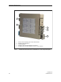
4-Leiter-Tragschienengerät
Deutsch. . . . . . . . . . . . . . . . . . . . . . . . . . . . . . . . . . . . . . . . . . . . . . . . . . . . . . . . . . . Seite 5
Instruction Manual
4-wire mounting rail device
English . . . . . . . . . . . . . . . . . . . . . . . . . . . . . . . . . . . . . . . . . . . . . . . . . . . . . . . . . . Page 75
SITRANS TW
A5E00054075-05
1
2
SITRANS TW
A5E00054075-05
Inhaltsverzeichnis
1 Technische Beschreibung . . . . . . . . . . . . . . . . . . . . . . . . . . . . . . . . . . . . . . . 7
1.1 Anwendungsbereich . . . . . . . . . . . . . . . . . . . . . . . . . . . . . . . . . . . . . . . . . . . . . . . . . . . . 7
1.2 Produktmerkmale. . . . . . . . . . . . . . . . . . . . . . . . . . . . . . . . . . . . . . . . . . . . . . . . . . . . . . . 8
1.3 Aufbau und Arbeitsweise . . . . . . . . . . . . . . . . . . . . . . . . . . . . . . . . . . . . . . . . . . . . . . . . . 9
1.3.1 Aufbau . . . . . . . . . . . . . . . . . . . . . . . . . . . . . . . . . . . . . . . . . . . . . . . . . . . . . . . . . . . 9
1.3.2 Hardware-Typschild . . . . . . . . . . . . . . . . . . . . . . . . . . . . . . . . . . . . . . . . . . . . . . . . 11
1.3.3 Arbeitsweise . . . . . . . . . . . . . . . . . . . . . . . . . . . . . . . . . . . . . . . . . . . . . . . . . . . . . . 11
2 Systemeinbindung . . . . . . . . . . . . . . . . . . . . . . . . . . . . . . . . . . . . . . . . . . . . 13
2.1 Systemkonfiguration . . . . . . . . . . . . . . . . . . . . . . . . . . . . . . . . . . . . . . . . . . . . . . . . . . . 13
2.2 Bediensoftware SIMATIC PDM . . . . . . . . . . . . . . . . . . . . . . . . . . . . . . . . . . . . . . . . . . . 14
3 Hardware-Funktionen . . . . . . . . . . . . . . . . . . . . . . . . . . . . . . . . . . . . . . . . . 15
3.1 Betriebsanzeige . . . . . . . . . . . . . . . . . . . . . . . . . . . . . . . . . . . . . . . . . . . . . . . . . . . . . . .
3.2 Prüfbuchse für Ausgangssignal . . . . . . . . . . . . . . . . . . . . . . . . . . . . . . . . . . . . . . . . . . .
3.3 Sensorfehler- / Grenzwertmelder. . . . . . . . . . . . . . . . . . . . . . . . . . . . . . . . . . . . . . . . . .
3.4 Anschluss HART-Kommunikation . . . . . . . . . . . . . . . . . . . . . . . . . . . . . . . . . . . . . . . . .
3.5 Änderung der Hardware . . . . . . . . . . . . . . . . . . . . . . . . . . . . . . . . . . . . . . . . . . . . . . . .
3.5.1 Öffnen und Schließen des Messumformers . . . . . . . . . . . . . . . . . . . . . . . . . . . . . .
3.5.2 Typschild herausnehmen und einlegen . . . . . . . . . . . . . . . . . . . . . . . . . . . . . . . . .
3.5.3 Umstellung Stromausgang auf Spannungsausgang . . . . . . . . . . . . . . . . . . . . . . .
3.5.4 HART-Schreibschutz . . . . . . . . . . . . . . . . . . . . . . . . . . . . . . . . . . . . . . . . . . . . . . .
3.6 Externe Vergleichsstellenkompensation mit Vergleichsstellenklemme 7NG3092-8AV .
3.6.1 Einsatz und Verwendung . . . . . . . . . . . . . . . . . . . . . . . . . . . . . . . . . . . . . . . . . . . .
3.6.2 Anschluss und Verdrahtung . . . . . . . . . . . . . . . . . . . . . . . . . . . . . . . . . . . . . . . . . .
3.6.3 Softwareparametrierung . . . . . . . . . . . . . . . . . . . . . . . . . . . . . . . . . . . . . . . . . . . . .
3.6.4 Bestellung . . . . . . . . . . . . . . . . . . . . . . . . . . . . . . . . . . . . . . . . . . . . . . . . . . . . . . . .
3.7 Strom-/Spannungsmessung über U/I-Eingangsstecker 7NG3092-8AW . . . . . . . . . . . .
3.7.1 Einsatz und Verwendung . . . . . . . . . . . . . . . . . . . . . . . . . . . . . . . . . . . . . . . . . . . .
3.7.2 Anschluss und Verdrahtung . . . . . . . . . . . . . . . . . . . . . . . . . . . . . . . . . . . . . . . . . .
3.7.3 Interner Aufbau . . . . . . . . . . . . . . . . . . . . . . . . . . . . . . . . . . . . . . . . . . . . . . . . . . . .
3.7.4 Softwareparametrierung . . . . . . . . . . . . . . . . . . . . . . . . . . . . . . . . . . . . . . . . . . . . .
3.7.5 Bestellung . . . . . . . . . . . . . . . . . . . . . . . . . . . . . . . . . . . . . . . . . . . . . . . . . . . . . . . .
15
15
16
16
17
17
18
18
19
20
20
20
21
21
21
21
22
22
23
24
4 Funktionen / Bedienung über HART . . . . . . . . . . . . . . . . . . . . . . . . . . . . . . 25
4.1 Betriebsdaten. . . . . . . . . . . . . . . . . . . . . . . . . . . . . . . . . . . . . . . . . . . . . . . . . . . . . . . . .
4.2 Parametrierbare Funktionen . . . . . . . . . . . . . . . . . . . . . . . . . . . . . . . . . . . . . . . . . . . . .
4.2.1 Leitungsbruchüberwachung und Kurzschlussprüfung . . . . . . . . . . . . . . . . . . . . . .
4.2.2 Abgleich Leitungswiderstände . . . . . . . . . . . . . . . . . . . . . . . . . . . . . . . . . . . . . . . .
4.2.3 Messen Leitungswiderstände . . . . . . . . . . . . . . . . . . . . . . . . . . . . . . . . . . . . . . . . .
4.2.4 Messwertoffset . . . . . . . . . . . . . . . . . . . . . . . . . . . . . . . . . . . . . . . . . . . . . . . . . . . .
4.2.5 Skalierungsfaktor . . . . . . . . . . . . . . . . . . . . . . . . . . . . . . . . . . . . . . . . . . . . . . . . . .
4.2.6 Referenzauswahl bei Messung mittels Thermoelement . . . . . . . . . . . . . . . . . . . . .
4.2.7 Differenzschaltung / Mittelwertschaltung . . . . . . . . . . . . . . . . . . . . . . . . . . . . . . . .
4.2.8 Netzfrequenzfilter / Messfrequenz . . . . . . . . . . . . . . . . . . . . . . . . . . . . . . . . . . . . .
4.2.9 Elektrische Dämpfung. . . . . . . . . . . . . . . . . . . . . . . . . . . . . . . . . . . . . . . . . . . . . . .
SITRANS TW
A5E00054075-05
25
27
27
27
27
27
27
28
28
28
28
1
4.2.10 Stromgeber / Spannungsgeber. . . . . . . . . . . . . . . . . . . . . . . . . . . . . . . . . . . . . . .
4.2.11 Alarmstrom / Alarmspannung . . . . . . . . . . . . . . . . . . . . . . . . . . . . . . . . . . . . . . . .
4.2.12 Sensorabgleich . . . . . . . . . . . . . . . . . . . . . . . . . . . . . . . . . . . . . . . . . . . . . . . . . . .
4.2.13 Stromgeberabgleich / Spannungsgeberabgleich . . . . . . . . . . . . . . . . . . . . . . . . .
4.2.14 Sonderkennlinie . . . . . . . . . . . . . . . . . . . . . . . . . . . . . . . . . . . . . . . . . . . . . . . . . .
4.2.15 Werkkalibrierung. . . . . . . . . . . . . . . . . . . . . . . . . . . . . . . . . . . . . . . . . . . . . . . . . .
4.2.16 Diagnosefunktionen . . . . . . . . . . . . . . . . . . . . . . . . . . . . . . . . . . . . . . . . . . . . . . .
4.2.17 Testfunktionen . . . . . . . . . . . . . . . . . . . . . . . . . . . . . . . . . . . . . . . . . . . . . . . . . . .
4.2.18 Simulation . . . . . . . . . . . . . . . . . . . . . . . . . . . . . . . . . . . . . . . . . . . . . . . . . . . . . . .
4.2.19 Parametriervarianten . . . . . . . . . . . . . . . . . . . . . . . . . . . . . . . . . . . . . . . . . . . . . .
4.3 Tipps zur HART-Communicator-Bedienung . . . . . . . . . . . . . . . . . . . . . . . . . . . . . . . . .
4.3.1 Hotkey-Taste . . . . . . . . . . . . . . . . . . . . . . . . . . . . . . . . . . . . . . . . . . . . . . . . . . . . .
29
29
30
31
32
34
34
39
39
41
42
42
5 Technische Daten . . . . . . . . . . . . . . . . . . . . . . . . . . . . . . . . . . . . . . . . . . . . 43
5.1 Fühlerarten / Messbereich / Digitale Genauigkeit / Leitungswiderstand . . . . . . . . . . . . 47
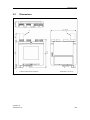
5.2 Maße . . . . . . . . . . . . . . . . . . . . . . . . . . . . . . . . . . . . . . . . . . . . . . . . . . . . . . . . . . . . . . . 49
6 Installation und Inbetriebnahme. . . . . . . . . . . . . . . . . . . . . . . . . . . . . . . . . . 51
6.1 Montage. . . . . . . . . . . . . . . . . . . . . . . . . . . . . . . . . . . . . . . . . . . . . . . . . . . . . . . . . . . . .
6.2 Einbau und Ausbau . . . . . . . . . . . . . . . . . . . . . . . . . . . . . . . . . . . . . . . . . . . . . . . . . . . .
6.3 Elektrischer Anschluss. . . . . . . . . . . . . . . . . . . . . . . . . . . . . . . . . . . . . . . . . . . . . . . . . .
6.4 Sensoreingangsbeschaltung . . . . . . . . . . . . . . . . . . . . . . . . . . . . . . . . . . . . . . . . . . . . .
6.4.1 Allgemeines . . . . . . . . . . . . . . . . . . . . . . . . . . . . . . . . . . . . . . . . . . . . . . . . . . . . . .
6.4.2 Sensoreingangsbeschaltungen . . . . . . . . . . . . . . . . . . . . . . . . . . . . . . . . . . . . . . .
6.5 Inbetriebnahme . . . . . . . . . . . . . . . . . . . . . . . . . . . . . . . . . . . . . . . . . . . . . . . . . . . . . . .
6.6 Auslieferungszustand der Betriebsdaten . . . . . . . . . . . . . . . . . . . . . . . . . . . . . . . . . . . .
6.6.1 Betriebsdaten gemäß werksseitigiger Grundeinstellung (Grundgerät). . . . . . . . . .
6.6.2 Werksseitig eingestellte kundenspezifische Betriebsdaten . . . . . . . . . . . . . . . . . .
51
51
52
55
55
56
57
58
58
58
7 Pflege und Wartung . . . . . . . . . . . . . . . . . . . . . . . . . . . . . . . . . . . . . . . . . . . 59
8 Bestelldaten . . . . . . . . . . . . . . . . . . . . . . . . . . . . . . . . . . . . . . . . . . . . . . . . . 61
8.1 Liste der parametrierbaren Betriebsdaten . . . . . . . . . . . . . . . . . . . . . . . . . . . . . . . . . . . 63
8.1.1 Liste der Betriebsdaten, Sonderbereiche . . . . . . . . . . . . . . . . . . . . . . . . . . . . . . . . 65
8.2 Ersatzteile . . . . . . . . . . . . . . . . . . . . . . . . . . . . . . . . . . . . . . . . . . . . . . . . . . . . . . . . . . . 66
9 Zertifikate . . . . . . . . . . . . . . . . . . . . . . . . . . . . . . . . . . . . . . . . . . . . . . . . . . . 67
10 Anhang. . . . . . . . . . . . . . . . . . . . . . . . . . . . . . . . . . . . . . . . . . . . . . . . . . . . 69
10.1 Technische Unterstützung . . . . . . . . . . . . . . . . . . . . . . . . . . . . . . . . . . . . . . . . . . . . . . 71
2
SITRANS TW
A5E00054075-05
Klassifizierung der Sicherheitshinweise
Dieses Handbuch enthält Hinweise, die Sie zu Ihrer persönlichen Sicherheit sowie zur Vermeidung von Sachschäden beachten müssen. Die Hinweise sind durch ein Warndreieck hervorgehoben und je nach Gefährdungsgrad folgendermaßen dargestellt:
GEFAHR
bedeutet, dass Tod oder schwere Körperverletzung eintreten wird, wenn die entsprechenden Vorsichtsmaßnahmen nicht getroffen werden.
WARNUNG
bedeutet, dass Tod oder schwere Körperverletzung eintreten kann, wenn die entsprechenden Vorsichtsmaßnahmen nicht getroffen werden.
VORSICHT
mit Warndreieck bedeutet, dass eine leichte Körperverletzung eintreten kann,
wenn die entsprechenden Vorsichtsmassnahmen nicht getroffen werden.
VORSICHT
ohne Warndreieck bedeutet, dass ein Sachschaden eintreten kann, wenn die entsprechenden Vorsichtsmaßnahmen nicht getroffen werden.
ACHTUNG
bedeutet, dass ein unerwünschtes Ergebnis oder Zustand eintreten kann, wenn
der entsprechenden Hinweis nicht beachtet wird.
☞
HINWEIS
ist eine wichtige Information über das Produkt, die Handhabung des Produktes
oder den jeweiligen Teil der Dokumentation, auf den besonders aufmerksam
gemacht werden soll und deren Beachtung wegen eines möglichen Nutzens
empfohlen wird.
Copyright © Siemens AG 2013 All rights reserved
Haftungsausschluss
Weitergabe sowie Vervielfältigung dieser Anleitung,
Verwertung und Mitteilung ihres Inhalts ist nicht
gestattet, soweit nicht ausdrücklich zugestanden.
Zuwiderhandlungen verpflichten zu Schadenersatz. Alle
Rechte vorbehalten, insbesondere für den Fall der
Patenterteilung oder GM-Eintragung
Wir haben den Inhalt der Anleitung auf Übereinstimmung mit
der beschriebenen Hard-und Software geprüft. Dennoch
können Abweichungen nicht ausgeschlossen werden, so
dass wir für die vollständige Übereinstimmung keine Gewähr
übernehmen. Die Angaben in dieser Anleitung werden
regelmäßig überprüft, und notwendige Korrekturen sind in
den nachfolgenden Auflagen enthalten. Für
Verbesserungsvorschläge sind wir dankbar.
Siemens AG
Sector Industry
Sensors and Communication
D-76181 Karlsruhe
SITRANS TW
A5E00054075-05
© Siemens AG 2013
Technische Änderungen bleiben vorbehalten
3
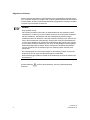
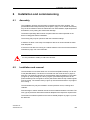
Allgemeine Hinweise
Dieses Gerät hat das Werk in sicherheitstechnisch einwandfreiem Zustand verlassen. Um diesen Zustand zu erhalten und um einen gefahrlosen Betrieb des Gerätes
sicherzustellen, sind die in dieser Betriebsanleitung gegebenen Hinweise und Warnvermerke vom Anwender zu beachten.
☞
HINWEIS
Sehr geehrter Kunde,
die Anleitung enthält aus Gründen der Übersichtlichkeit nicht sämtliche Detailinformationen zu allen Typen des Produkts und kann auch nicht jeden denkbaren
Fall der Aufstellung, des Betriebs oder der Instandhaltung berücksichtigen.
Außerdem weisen wir darauf hin, dass der Inhalt der Anleitung nicht Teil einer früheren oder bestehenden Vereinbarung, Zusage oder eines Rechtsverhältnisses
ist oder diese abändern soll. Sämtliche Verpflichtungen der Siemens AG ergeben
sich aus dem jeweiligen Kaufvertrag, der auch die vollständige und allein gültige
Gewährleistungsregelung enthält. Diese vertraglichen Gewährleistungsbestimmungen werden durch die Ausführungen der Anleitung weder erweitert noch
beschränkt.
Der Inhalt spiegelt den technischen Stand zur Drucklegung wieder. Technische
Änderungen sind im Zuge der Weiterentwicklung vorbehalten.
Diese Anleitung gilt sowohl für Geräte mit Ex-Zulassung als auch für Geräte ohne
Ex-Zulassung.
Zeichenerklärung
beachten“.
4
!
auf dem Gerät bedeutet, „Achtung, Betriebsanleitung
SITRANS TW
A5E00054075-05
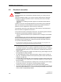
WARNUNG
Beim Betrieb elektrischer Geräte stehen zwangsläufig bestimmte Teile dieser
Geräte unter gefährlicher Spannung. Bei Nichtbeachten der Warnhinweise können deshalb schwere Körperverletzungen und/oder Sachschäden auftreten.
Der Stecker für die Stromversorgung des Gerätes darf niemals unter Spannung
gesteckt oder herausgezogen werden. Bei der Geräteinstallation ist ein in der
Nähe befindlicher und als zugehörig gekennzeichneter Netzschalter vorzusehen.
Weil das Gerät berührgefährliche Klemmen enthält, darf das Gerät nur in
geschlossenen Betriebsräumen, Gehäusen und Schränken, zu denen ausschließlich qualifiziertes Personal Zutritt hat, installiert werden.
Nur entsprechend qualifiziertes Personal darf an diesem Gerät oder in dessen
Nähe arbeiten.
Das Gerät ist in einem geschlossenen Schrank oder in einem geschlossenen
Gehäuse zu montieren, das bezüglich der mechanischen Festigkeit den Anforderungen der DIN EN 61010-1 oder einer anderen Produktsicherheitsnorm für elektrische Geräte entspricht. Ein Betrieb des Gerätes ohne Umgehäuse, wie z. B.
Schaltschrank, Verteilerkasten usw., ist nicht zulässig.
Dieses Personal muss gründlich mit dieser Betriebsanleitung vertraut sein.
Geräte der Zündschutzart Eigensicherheit verlieren ihre Zulassung, wenn sie an
anderen Stromkreisen betrieben werden, als es der EG-Baumusterprüfbescheinigung entspricht (vor allem zu beachten in Kapitel 6, Seite 51).
Der einwandfreie und sichere Betrieb dieses Gerätes setzt sachgemäßen Transport, fachgerechte Lagerung, Aufstellung und Montage sowie sorgfältige Bedienung voraus.
Das Gerät darf nicht bei geöffnetem Gehäuse betrieben werden.
Das Gerät darf nur zu den in dieser Betriebsanleitung vorgegebenen Zwecken
eingesetzt werden.
Sämtliche nicht explizit erlaubte Änderungen am Gerät bedürfen der ausdrücklichen Zustimmung des Herstellers.
VORSICHT
Elektrostatisch gefährdete Baugruppen können durch Spannungen zerstört werden, die weit unterhalb der Warnehmungsgrenze des Menschen liegen. Diese
Spannungen treten bereits auf, wenn Sie ein Bauelement oder elektrische
Anschlüsse einer Baugruppe berühren, ohne elektrostatisch entladen zu sein.
Der Schaden, der an einer Baugruppe auf Grund einer Überspannung auftritt,
kann meist nicht sofort erkannt werden, sondern macht sich erst nach längerer
Betriebszeit bemerkbar.
SITRANS TW
A5E00054075-05
5
Qualifiziertes Personal
sind Personen, die mit der Aufstellung, Montage, Inbetriebsetzung und Betrieb des
Produktes vertraut sind und über die ihrer Tätigkeit entsprechenden Qualifikationen
verfügen, wie z. B.:
•
•
•
•
Ausbildung oder Unterweisung bzw. Berechtigung, Stromkreise und Geräte bzw.
Systeme gemäß den Standards der Sicherheitstechnik für elektrische Stromkreise ein- und auszuschalten, zu erden, zu kennzeichnen und zu warten.
Ausbildung oder Unterweisung gemäß den Standards der Sicherheitstechnik in
Pflege und Gebrauch angemessener Sicherheitsausrüstung.
Schulung in Erster Hilfe.
Bei Geräten mit Explosionsschutz: Ausbildung oder Unterweisung bzw. Berechtigung, Arbeiten an elektrischen Kreisen für explosionsgefährdete Anlagen
durchzuführen.
Haftungsausschluss
Sämtliche Änderungen am Gerät, sofern sie nicht in der Anleitung ausdrücklich erwähnt werden, fallen in die Verantwortung des Anwenders.
Marken
SIMATIC®, SIPART®, SIREC®, SITRANS® sind eingetragene Marken der
Siemens AG
Die übrigen Bezeichnungen in dieser Anleitung können Marken sein, deren Benutzung durch Dritte für deren Zwecke die Rechte der Inhaber verletzen können.
6
SITRANS TW
A5E00054075-05
Technische Beschreibung
1
1.1
Technische Beschreibung
Anwendungsbereich
Der SITRANS TW, 4-Leiter-Tragschienengerät ist ein Messumformer mit universeller Eingangsschaltung zum Anschluss an folgende Fühler und Signalquellen:
•
•
•
•
•
Widerstandsthermometer
Thermoelemente
Widerstandsgeber / Potentiometer
mV-Geber
Als Sondervariante:
- V-Geber
- Stromquellen
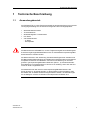
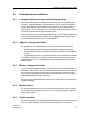
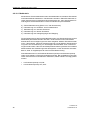
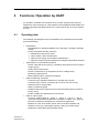
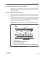
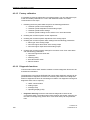
WARNUNG
Der Messumformer SITRANS TW, 4-Leiter-Tragschienengerät ist ein Wartengerät.
Er darf als zugehöriges Betriebsmittel immer nur außerhalb des explosionsgefährdeten Bereiches montiert werden.
Die Messumformer in der Ausführung „Zündschutzart Eigensicher“ besitzen eine
EG-Baumusterprüfbescheinigung und erfüllen die entsprechenden harmonisierten
europäischen Normen der CENELEC. Sie können zur Messung von Prozessgrößen in gas-explosionsgefährdeten Bereichen (Zone 1, 0) verwendet werden.
Eine Messung von Prozessgrößen in Zone 0 ist nur zulässig, wenn auch die Sensoren für Zone 0 zugelassen sind.
Der Messumformer darf auch für staub-explosionsgefährdete Bereiche der
Zonen 20 bzw. 21 eingesetzt werden. In diesen Fällen ist sicherzustellen, dass
die Geräte, die an diesen Stromkreis angeschlossen werden, die Anforderungen
für die Kategorie 1D bzw. 2D erfüllen und entsprechend zertifiziert sind.
SITRANS TW
A5E00054075-05
7
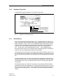
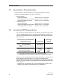
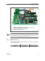
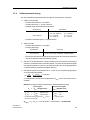
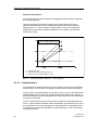
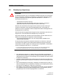
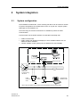
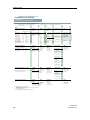
Technische Beschreibung
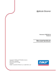
Warte
Feld
Zone 1
Zone 0
1 Messumformer
2 Feldgehäuse (bei Bedarf, handelsüblich)
*) Nur in Verbindung mit den vorgeschriebenen Schutzanforderungen für den Sensor
Bild 1
1.2
Produktmerkmale
•
•
•
•
•
•
•
•
•
•
•
•
•
8
Einsatzgebiete der Messumformer in Ex- und in Nicht-Ex-Ausführung
Messumformer in Vierleitertechnik mit HART-Schnittstelle
Gehäuse zur Montage auf Hutschiene 35 mm oder G-Schiene 32 mm
Schraub-Steckverbinder
galvanische Trennung aller Kreise
Ausgangssignal 0/4 ... 20 mA oder 0/2 ... 10 V
lieferbar in den Netzteilvarianten UH 230 V oder UH 24 V
Explosionsschutz [ Ex ia ] bzw. [ Ex ib ] für 7NG3242-1 zur Messung von
Prozessgrößen im Ex-Bereich bei entsprechender Geräteausführung (Gas- und
Staub-Ex)
temperaturlineare Kennlinie für alle Temperaturfühler
anwenderspezifische Kennlinien
automatische Korrektur von Nullpunkt und Messspanne
Überwachung des Fühlers und seiner Zuleitung auf Bruch und Kurzschluss
Sensorfehler und / oder Grenzwert über einen optionalen SensorfehlerGrenzwertmelder (Melderelais) ausgebbar
Hardware-Schreibschutz für HART-Kommunikation
SITRANS TW
A5E00054075-05
Technische Beschreibung
1.3
Aufbau und Arbeitsweise
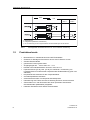
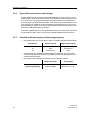
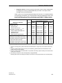
1.3.1
Aufbau
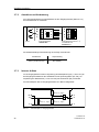
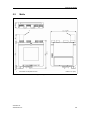
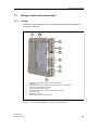
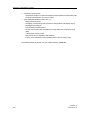
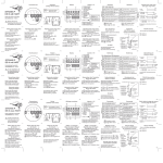
Der Aufbau des SITRANS TW, 4-Leiter-Tragschienengerät ist in Bild 2 und in
Bild 3, Seite 10 dargestellt.
.
1
2
3
4
5
6
7
8
9
Bild 2
SITRANS TW
A5E00054075-05
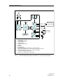
Zusätzliches Typschild bei explosionsgeschützter Geräteausführung
Typschild
Schraub-Steckverbinder für Ausgang und HART-Modem zur vor-Ort-Bedienung
Schraub-Steckverbinder für Relaisausgang
Prüfbuchse für Ausgangssignal Strom
Schraub-Steckverbinder für Hilfsenergie und Schutzleiteranschluss
Betriebsanzeige
Schraub-Steckverbinder
Entriegelung der Klarsichtabdeckung
Geräterückansicht Messumformer SITRANS TW, 4-Leiter-Tragschienengerät
9
Technische Beschreibung
1
2
3
4
5
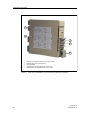
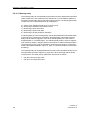
Bild 3
10
Schild für Anschlussbelegung der Schraub-Steckverbinder
Entriegelung der Gehäusefront
Hutschienenadapter
Entriegelung des Hutschienenadapters vom Gehäuse
Entriegelung des Hutschienenadapters von einer G- oder H-Schiene
Geräterückansicht Messumformer SITRANS TW, 4-Leiter-Tragschienengerät
SITRANS TW
A5E00054075-05
Technische Beschreibung
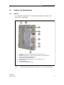
1.3.2
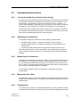
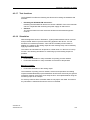
Hardware-Typschild
Folgendes Bild zeigt ein Beispiel für ein Hardware-Typschild.
D-76181 Karlsruhe
0044
a
Hardware-Ausgabestand
Firmware-Ausgabestand
HART-Document-Revision
Gerätetyp
Bild 4
1.3.3
Beispiel für Hardware-Typschild
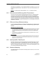
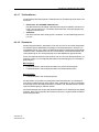
Arbeitsweise
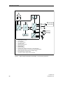
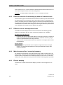
Das von einem Widerstandsgeber (Zwei-, Drei-, Vierleiterschaltung), Spannungsgeber, Stromgeber oder Thermoelement gelieferte Messsignal wird in einem AnalogDigital-Umsetzer (1, Bild 5, Seite 12) in ein digitales Signal umgewandelt. Dieses
wird in einem Microcontroller (2) ausgewertet, entsprechend der Sensorkennlinie
korrigiert und in einem Digital-Analog-Umsetzer (5) in einen Ausgangsstrom
(0/4 ... 20mA) oder in eine Ausgangsspannung (0/2 ... 10V) umgewandelt. Die
Sensorkennlinien sowie die zur Parametrierung des Messumformers notwendigen
Daten sind in einem nichtflüchtigen Speicher (3) hinterlegt.
Als Hilfsenergie (f) sind Wechsel- oder Gleichspannungen einsetzbar. Durch einen
Brückengleichrichter im Netzteil ist ein beliebiges Anklemmen der Hilfsenergie möglich. Ein Anschluss des Gerätes an Schutzleiter ist aus Sicherheitsgründen erforderlich.
Das HART-Modem bzw. ein HART-Communicator ermöglicht die Parametrierung
des Messumformers über ein Protokoll gemäß HART-Spezifikation. Über die HARTAusgangsklemmen (c) kann der Messumformer direkt an der Messstelle parametriert werden.
Die Betriebsanzeige (4) meldet den ungestörten oder gestörten Betriebszustand
des Messumformers. Ein Melderelais (7) ermöglicht die Signalisierung von Sensorfehlern und / oder Grenzwertüber- bzw. unterschreitungen. Über die Prüfbuchse (e)
kann bei Stromausgang der 0/4 ... 20mA-Strom mit einem Messgerät kontrolliert
werden.
SITRANS TW
A5E00054075-05
11
Technische Beschreibung
HART Modem/
Communicator
Ausgang
U oder I
Messgerät
0/4 - 20mA
Netz-
teil
1
2
3
4
5
6
7
a
b
c
d
e
f
Bild 5
12
Analog-Digital-Umsetzer
Microcontroller
nichtflüchtiger Speicher
Betriebsanzeige
Digital-Analog-Umsetzer
Netzteil
Melderelais
Sensoranschluss
Melderelaisausgang für Sensorfehler- / Grenzwertmelder
HART-Ausgangsklemmen zum Anschluss der Vorort-Parametrierung
Analoger Messausgang (Strom- bzw. Spannungsausgang)
Prüfbuchse (nur bei Stromausgang)
Anschluss von Hilfsenergie und Schutzleiter
Blockschaltbild Messumformer SITRANS TW, 4-Leiter-Tragschienengerät
SITRANS TW
A5E00054075-05
Systemeinbindung
2
2.1
Systemeinbindung
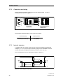
Systemkonfiguration
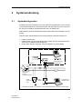
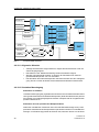
Der Messumformer SITRANS TW, 4-Leiter-Tragschienengerät kann in einer Vielzahl
von Systemkonfigurationen eingesetzt werden: als Stand-Alone-Version oder auch
als Teil einer komplexen Systemlandschaft, wie z.B. SIMATIC S7.
Dabei steht die gesamte Gerätefunktionalität mittels HART-Kommunikation zur Verfügung.
Über die HART-Schnittstelle kann die Kommunikation wahlweise erfolgen mit:
•
HART-Communicator
HART-Modem mit nachgeschaltetem PC / Laptop, auf dem die geeignete Software wie z.B. SIMATIC PDM verfügbar ist
einem HART-fähigen Leitsystem (wie z.B. SIMATIC S7 mit ET200M)
•
•
diese Verbindung
hier auftrennen!
Leitsystem
oder
Bürde 1)
Messumformer
Sitrans TW,
4-LeiterTragschienengerät
HARTModem
HARTCommunicator
PC/Laptop mit
SIMATIC PDM
oder
1)
Bild 6
SITRANS TW
A5E00054075-05
Bei Einsatz mit HART-Kommunikation muss der Bürdenwiderstand mindestens 230Ω betragen
Beispiele für mögliche Systemkonfigurationen
13
Systemeinbindung
2.2
Bediensoftware SIMATIC PDM
SIMATIC PDM ist ein Softwarepaket zur Projektierung, Parametrierung, Inbetriebnahme, Diagnose und Wartung des SITRANS TW, 4-Leiter-Tragschienengerät und
anderer Prozessgeräte.
SIMATIC PDM enthält eine einfache Prozessbeobachtung der Prozesswerte,
Alarme und Zustandsinformationen des Gerätes.
Es gibt zwei Versionen, die unter Windows NT oder Windows 95/98 laufen:
•
•
SIMATIC PDM (Stand alone)
SIMATIC PDM integriert
Weitere Informationen siehe Bedienhandbuch SIMATIC PDM oder Katalog FI01.
14
SITRANS TW
A5E00054075-05
Hardware-Funktionen
3
3.1
Hardware-Funktionen
Betriebsanzeige
Die grüne Betriebsanzeige (5, Bild 2, Seite 9) dient zur Signalisierung folgender
Betriebszustände:
•
•
•
fehlende Hilfsenergie:
ungestörter Betrieb:
gestörter Betrieb
− Diagnosealarm
→ Sensorfehler:
→ Hardware- / Firmwarefehler:
− Diagnosewarnung
→ Grenzwert über- / unterschritten:
→ Ausgangssättigungswarnung:
→ Messwert außerhalb Sensorlimits
Betriebsanzeige leuchtet nicht
Betriebsanzeige leuchtet
Betriebsanzeige blinkt
Blinkfrequenz = 1 Hz (Priorität 1)
Blinkfrequenz = 1 Hz (Priorität 1)
Blinkfrequenz = 5 Hz (Priorität 2)
Blinkfrequenz = 1 Hz (Priorität 3)
Blinkfrequenz = 1 Hz (Priorität 4)
Treten mehrere Fehler gleichzeitig auf, so erfolgt das Blinken entsprechend der
angegebenen Priorität (Priorität 1 = höchste Priorität)
3.2
Prüfbuchse für Ausgangssignal
•
•
•
SITRANS TW
A5E00054075-05
Die Prüfbuchse (6, Bild 2, Seite 9) dient bei Stromausgang zur Kontrolle des
0/4 bis 20-mA-Stromes mit einem Messgerät. Der Anschluss erfolgt über Prüfstecker 2 mm. Der Spannungsabfall am Strommesser darf dabei 0,3 V bei
23-mA-Ausgangsstrom nicht überschreiten.
Bei Spannungsausgang hat die Prüfbuchse keine Funktion.
Befindet sich der Analogausgang im Modus Stromausgang 0 bis 20mA oder im
Modus Spannungsausgang 0 bis 10 V, so ist für eine korrekte HARTKommunikation bei 0 mA bzw. bei 0 V die Prüfbuchse zu überbrücken. Ein entsprechender Kurzschlussstecker kann als Zubehörteil wie folgt bestellt werden:
− Bestellnummer des SITRANS TW um die Kurzangabe S01 erweitern oder
− Bestellung als Zubehörteil mit Bestellnummer 7NG3092-8AP
15
Hardware-Funktionen
3.3
Sensorfehler- / Grenzwertmelder
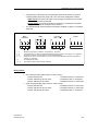
Der Sensorfehler- / Grenzwertmelder ist wie folgt parametrierbar (Anschlussbelegung des Relaisausganges siehe Bild 19, Seite 53).
•
•
3.4
Ruhestromprinzip
− Gerät ausgeschaltet:
− Gerät eingeschaltet und kein Fehler:
− Gerät eingeschaltet und Fehler:
Arbeitsstromprinzip
− Gerät ausgeschaltet:
− Gerät eingeschaltet und kein Fehler:
− Gerät eingeschaltet und Fehler:
Klemme 10 und 11 verbunden
Klemme 9 und 11 verbunden
Klemme 10 und 11 verbunden
Klemme 10 und 11 verbunden
Klemme 10 und 11 verbunden
Klemme 9 und 11 verbunden
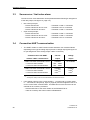
Anschluss HART-Kommunikation
•
Der Anschluss des HART-Modems bzw. des HART-Communicators ist je nach
Typ des Analogausganges (Strom- oder Spannungsausgang) wie folgt vorzunehmen (Anschlussbelegung des Analogausganges / HART-Anschlusses siehe
Bild 19, Seite 53:
Kommunikation mit HART-Modem
/ HART-Communicator
Stromausgang
ausgang
HART-Anschluss an Klemme 5 und 6
→ RBürde bei HART-Modem
→ RBürde bei HART-Communicator
möglich
230 bis 500 Ω
230 bis 650 Ω
nicht möglich
HART-Anschluss an Klemme 7 und 8
→ RBürde bei HART-Modem
→ RBürde bei HART-Communicator
möglich
keine1) 2)
keine1) 2)
möglich
keine1)
keine1)
1)
2)
•
16
Spannungs-
Es darf keine Bürde zwischen die Klemmen 7 und 8 angeschlossen werden.
Es muss eine Bürde (max. 650Ω) zwischen die Klemmen 5 und 6 angeschlossen werden.
Befindet sich der Analogausgang im Modus Stromausgang 0 .bis 20mA oder im
Modus Spannungsausgang 0 bis 10 V, so ist für eine korrekte HARTKommunikation bei 0 mA bzw. bei 0 V die Prüfbuchse (6, Bild 2, Seite 9) zu überbrücken. Ein entsprechender Kurzschlussstecker kann als Zubehörteil wie folgt
bestellt werden:
− Bestellnummer des SITRANS TW um die Kurzangabe S01 erweitern oder
− Bestellung als Zubehörteil mit Bestellnummer 7NG3092-8AP
SITRANS TW
A5E00054075-05
Hardware-Funktionen
3.5
Änderung der Hardware
WARNUNG
Die Baugruppe enthält elektrostatisch gefährdete Bauelemente. Vorsichtsmaßnahmen beachten!
ACHTUNG
Hardwareparametrierungen am Gerät müssen auf dem Hardware-Typschild mit
einem wasser- sowie wischfestem Filzstift dokumentiert werden. Das HardwareTypschild befindet sich unter dem austauschbaren Typschild mit den Betriebsdaten.
WARNUNG
Es dürfen nur Hardware-Änderungen vorgenommen werden, die auch in den folgenden Kapiteln beschrieben werden. Anderenfalls verlieren Ex-Geräte dadurch
ihre Ex-Zulassung.
3.5.1
Öffnen und Schließen des Messumformers
Stromversorgung ausschalten. Schraub-Steckverbinder (1-4, Bild 2, Seite 9) ziehen.
Hutschienenadapter (3, Bild 3, Seite 10) durch Drücken der Verriegelungszunge (4,
Bild 3, Seite 10) entriegeln und seitlich herausschieben. Klarsichtabdeckung für Typschild mit den Betriebsdaten gemäß Kapitel 3.5.2, Seite 18 herausziehen. Gehäusefront entriegeln (2, Bild 3, Seite 10), Frontteil abziehen und Baugruppe
herausziehen.
Das Schließen des Messumformers erfolgt in umgekehrter Reihenfolge. Dabei muss
gewährleistet werden, dass das Gehäuse sicher verschlossen wird und die Blende
einrastet. Es dürfen keine leitenden Teile lose im Gerät verbleiben.
SITRANS TW
A5E00054075-05
17
Hardware-Funktionen
3.5.2
Typschild herausnehmen und einlegen
Klarsichtabdeckung für Typschild mit den Betriebsdaten (7, Bild 2, Seite 9) an der
Stelle (9, Bild 2, Seite 9) mit einem kleinen Schraubendreher in Richtung Front anheben, bis sie auch auf der gegenüberliegenden Seite ausrastet, und herausziehen.
Das eingelegte Typschild ist austauschbar. Unter diesem Typschild befindet sich auf
dem Gehäuse ein Aufkleber mit den Grunddaten des Messumformers. Ein neues
Betriebsdatentypschild an der entsprechend markierten Stelle falzen und dann in die
Führung der Klarsichtabdeckung einlegen.
Nach dem Wiedereinschieben der Klarsichtabdeckung muss diese durch den Druck
auf die Stelle (9, Bild 2, Seite 9) und auf die gegenüberliegende Seite einrasten.
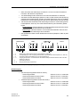
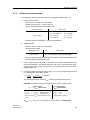
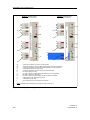
3.5.3
Umstellung Stromausgang auf Spannungsausgang
•
•
•
18
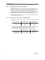
Die Steckbrücken X6, X7, X8 (Bild 7, Seite 19) gemäß folgender Tabelle setzen:
Steckbrücke
Stromausgang
Spannungsausgang
X6
X7
X8
offen
offen
geschlossen
geschlossen
geschlossen
offen
Anschließend über die Bediensoftware SIMATIC PDM bzw. über den HARTCommunicator die hardwareseitig eingestellte Art des Analogausganges auch
softwaremäßig einstellen
Beschriftung des Hardware-Typschildes gemäß folgender Tabelle
Geräte-Bestell-Nr.
Ausgangsart
Stromausgang
7NG3242-xxAxx
Ankreuzen von 20 mA
Spannungsausgang
7NG3242-xxBxx
Ankreuzen von 10 V
SITRANS TW
A5E00054075-05
Hardware-Funktionen
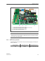
X6
X6
X7
X8
X9
Bild 7
☞
3.5.4
X7
X8
X9
Steckbrücke für Ausgangsart (Strom oder Spannung)
(In einigen Geräteausführungen kann X6 auch eine gebogene Steckbrücke sein)
Steckbrücke für Ausgangsart (Strom oder Spannung)
Steckbrücke für Ausgangsart (Strom oder Spannung)
Steckbrücke für HART-Schreibschutz
Hardware-Optionen des SITRANS TW, 4-Leiter-Tragschienengerät
HINWEIS
Durch eine Umschaltung von Stromausgang auf Spannungsausgang und umgekehrt ändert sich die Genauigkeit der Ausgangsstufe nicht.
HART-Schreibschutz
Über das Stecken der Brücke X9 (Bild 7) kann das Parametrieren des Messumformers unterbunden werden.
SITRANS TW
A5E00054075-05
Steckbrücke
Schreibschutz ein
Schreibschutz aus
X9
geschlossen
offen (Lieferzustand)
19
Hardware-Funktionen
3.6
Externe Vergleichsstellenkompensation mit Vergleichsstellenklemme 7NG3092-8AV
3.6.1
Einsatz und Verwendung
Sie dient bei Geräten mit der Bestellbezeichnung 7NG3242-****0 in der Messart
Thermoelement mit externer Vergleichsstellenkompensation als Vergleichsstellenklemme.
Die Grundgenauigkeit der Vergleichsstellenklemme beträgt 0,5 °C (PT100 DIN IEC
751, Grenzwertklasse B).
Für Anwendungsfälle mit verminderten Genauigkeitsanforderungen an die Vergleichsstellenmessung (≤ 3 °C) kann auch die interne Vergleichsstellenkompensation des Gerätes verwendet werden.
WARNUNG
Bei Geräten in der Ausführung "Zündschutzart Eigensicher" ist vor Inbetriebnahme
der Geräte sicherzustellen, dass die Vergleichsstellenklemme 7NG3092-8AV und
der Eingangsstecker fest im werksseitig mitgelieferten blauen Kabelgehäuse montiert sind.
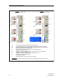
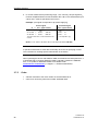
3.6.2
Anschluss und Verdrahtung
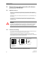
Die Vergleichsstellenklemme sowie das Thermoelement sind gemäß Bild 8 auf den
Eingangsstecker (Klemme 1-4) des SITRANS TW zu montieren.
Die in der Anschaltungsart Thermoelement mit externer Vergleichsstellenkompensation notwendige Verdrahtung der Klemmen 3 und 4 (Kapitel 6.4.2, Seite 56) entfällt.
Sie ist bereits innerhalb der Vergleichsstellenklemme realisiert.
PT100 DIN IEC 751
Eingangsstecker
(Klemme 1-4)
von SITRANS TW
7NG3242-****0
Bild 8
20
1
1
2
2
3
3
4
4
Vergleichsstellenklemme
7NG3092-8AV
Anschluss an Klemme 2
+
Anschluss an Klemme 3
Thermoelement
Anschluss Vergleichsstellenklemme und Thermoelement
SITRANS TW
A5E00054075-05
Hardware-Funktionen
3.6.3
Softwareparametrierung
In der Parametriersoftware (HART-Communicator oder SIMATIC PDM) ist als Typ
der Vergleichsstellenkompensation "externer PT100" zu wählen.
3.6.4
Bestellung
•
•
Bestellnummer des SITRANS TW um die Kurzangabe S02 erweitern oder
Bestellung als Zubehörteil mit Bestellnummer 7NG3092-8AV
3.7
Strom-/Spannungsmessung über U/I-Eingangsstecker
7NG3092-8AW
3.7.1
Einsatz und Verwendung
Sie dient bei Geräten mit der Bestellbezeichnung 7NG3242-0***0 als Messvorsatz
für:
•
•
Spannungsmessung im Messbereich:
Strommessung im Messbereich:
-1,2 bis 10 V DC oder
-12 bis 100 mA DC
Die Grundgenauigkeit des U/I-Eingangssteckers beträgt: 0,1 %.
Die minimale Messspanne beträgt bei:
•
•
Spannungsmessung (Messbereich -1,2 bis 10 V): 0,05 V
Strommessung (Messbereich -12 bis 100 mA):
0,41 mA
WARNUNG
Der U/I-Eingangsstecker darf in explosionsgefährdeten Bereichen nicht eingesetzt
werden.
SITRANS TW
A5E00054075-05
21
Hardware-Funktionen
3.7.2
Anschluss und Verdrahtung
-12..100mA -1,2..10V
Der U/I-Eingangsstecker ist gemäß Bild 9 auf den Eingangsstecker (Klemme 1-4)
des SITRANS TW zu montieren.
U+
A
B
C
UI+
I-
Sensor
Bild 9
4
4
3
3
2
1
2
1
U/I-Eingangsstecker
7NG3092-8AV
Eingangsstecker (Klemme 1-4)
von SITRANS TW
7NG3242-0***0
Anschluss U/I-Eingangsstecker an SITRANS TW
Die hardwaremäßige Parametrierung ist wie folgt vorzunehmen:
3.7.3
Messbereich
Jumperstellung
Spannung (-1,2 bis 10 V)
Strom (-12 bis 100 mA)
A-B
B-C (default)
Interner Aufbau
Im U/I-Eingangsstecker wird zur Anpassung der Messspannungen (-1,2 bis 10 V) an
den Eingangsmessbereich des SITRANS TW ein Spannungsteiler (R1, R2), zur
Anpassung der Messströme (-12 bis 100 mA) ein Stromshunt (R3) verwendet.
Der Stromlaufplan des U/I-Eingangssteckers ist in Bild 10 dargestellt.
U+
4
R1
996k / 0.1%, 25ppm
A
B
C
UI+
R3
10R / 0.1%, 15ppm
22
2
R2
100k / 0.1%, 15ppm
IBild 10
3
1
Stromlaufplan U/I-Eingangsstecker
SITRANS TW
A5E00054075-05
Hardware-Funktionen
3.7.4
Softwareparametrierung
Bei der Parametrierung des Steckers ist folgende Reihenfolge zu beachten:
1. HART-Communicator
− Auswahl Sensorklasse = mV-Geber
− Auswahl Sensortyp = -120 bis 1000 mV
− Eingabe folgender Sonderkennlinienpaare:
Messbereich
Wertepaare
-1,2 bis 10 V
-12 bis 100 mA
X1 = -109,4891 mV
X2 = 912, 4088 mV
Y1 = -1,2000 V
Y2 = 10,0000 V
X1 = -120 mV
X2 = 1000 mV
Y1 = -12 mA
Y2 = 100 mA
− Auswahl Linearisierungsart = Sonderkennlinie
2. SIMATIC PDM
− Auswahl Sensorklasse = mV-Geber
− Auswahl Sensortyp:
Messbereich
-1,2 bis 10 V
-12 bis 100 mA
Sensortyp
-1,2 bis 10 V (mit U/I-Stecker (7NG3092-8AW)
-12 bis 100 mA (mit U/I-Stecker 7NG3092-8AW)
− Die entsprechenden Sonderkennlinienpaare sowie die Linearisierungsart wer-
den durch SIMATIC PDM automatisch gesetzt.
3. Soll der U/I-Eingangsstecker in Zusammenhang mit einer anderen ("kundenspezifischen") Sonderkennlinie verwendet werden, so ist bei der Kennlinieneingabe
der Spannungsteiler R1, R2 bzw. der Stromshunt R3 des U/I-Eingangssteckers
zu berücksichtigen (siehe Stromlaufplan Bild 10).
4. Bei Spannungsmessung (Messbereich -1,2 bis 10 V) sind alle Eingangssignale
Xi mit dem Spannungsteiler:
100 kW
R2
=
= 0,09124087
R =
996 kW + 100 kW
T R1+R2
zu multiplizieren. Die Kennlinieneingabewerte XSKL,i sind in der Einheit mV anzugeben.
Beispiel: (V-Signal entspricht physikalisch Sauerstoffgehalt [%O2])
Xi
->
X1: 1 V
X2: 7 V
Xn: 8 V
->
->
->
Sensorsignal
XSKL,i (Eingabewerte)
XSKL,1:
XSKL,2:
XSKL,n:
91,2409 mV
638,6861 mV
729,9270 mV
Die Eingabe der Eingangswerte XSKL,i muss in
der Einheit mV erfolgen.
linearisiertes Signal
YSKL,i (Eingabewerte)
YSKL,1:
YSKL,2:
YSKL,n:
3**
21**
35**
** entspricht [%O2]
(XSKL,1 = X1 x RT = 1 V x 0,09124087 = 0,09124087 V = 91,2409 mV)
SITRANS TW
A5E00054075-05
23
Hardware-Funktionen
5. Bei Strommessung (Messbereich -12 bis 100 mA) sind alle Eingangssignale Xi
mit dem Stromshunt RS = R3 = 10 Ω zu multiplizieren. Die Kennlinieneingabewerte XSKL,i sind in der Einheit mV anzugeben.
Beispiel: (mA-Signal entspricht physikalisch Höhenstand [m])
Xi
->
X1: 10 mA ->
X2: 70 mA ->
Xn: 80 mA ->
Sensorsignal
XSKL,i (Eingabewerte)
XSKL,1:
XSKL,2:
XSKL,n:
100 mV
700 mV
800 mV
Die Eingabe der Eingangswerte XSKL,i muss in
der Einheit mV erfolgen.
linearisiertes Signal
YSKL,i (Eingabewerte)
YSKL,1:
YSKL,2:
YSKL,n:
1**
5**
7**
** entspricht [m]
(XSKL,1 = X1 x RS = 10 mA x 10 Ω = 10 mA x 10 V/A = 100 mV)
☞
HINWEIS
Bei Verwendung des U/I-Eingangsstecker wird geräteintern eine Sonderkennlinie
verwendet. Dadurch wird eine im Gerät bereits vorhandene Sonderkennlinie überschrieben.
Bei Bedienung des Gerätes mit SIMATIC PDM wird die PDM-Device Description
Rev. 2 des SITRANS TW benötigt. (In SIMATIC PDM 5.2 ist die PDM-DD Rev. 2
bereits enthalten. Für SIMATIC PDM ab V6.0 steht ein Update unter
www.siemens.de/sitranst (-> Support / -> Software Downloads) zur Verfügung.
3.7.5
Bestellung
•
•
24
Bestellnummer des SITRANS TW um die Kurzangabe S03 erweitern oder
Bestellung als Zubehörteil mit Bestellnummer 7NG3092-8AW
SITRANS TW
A5E00054075-05
Funktionen / Bedienung über HART
4
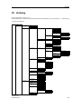
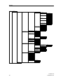
Funktionen / Bedienung über HART
Für die Bedienung über HART ist die Verwendung eines HART-Communicators
(Menüstruktur siehe Anhang) oder einer PC-Software wie SIMATIC PDM notwendig.
Die Bedienung dieser Werkzeuge entnehmen Sie bitte den zugehörigen Betriebsanleitungen bzw. Online-Hilfen.
4.1
Betriebsdaten
Folgende Betriebsdaten können zum Messumformer übertragen und vom Messumformer abgefragt werden:
•
•
•
•
SITRANS TW
A5E00054075-05
Identifikation
− Angaben zur Betriebssicherheit: Tag, Beschreibung, Nachricht, Montagenummer
− Geräteangaben (diese Angaben sind nur lesbar):
→ Hersteller und Produktname
→ Bestellnummer, Geräte-Seriennummer
→ Angaben zu Hilfsenergie und Hardware-Schreibschutz
→ Revisionsnummern (Universal-, Feldgeräte-, Software- und HardwareRevision)
Angaben zum Messverfahren
− Sensorklasse und Sensortyp (z.B. Widerstandsthermometer Pt100 oder
Thermoelement Typ B)
− Skalierungsfaktor des Sensors
− Sensorkennlinie (z.B. temperaturlinear oder spannungslinear)
− Messbereich und Messeinheit
− Netzfrequenzfilter / Messfrequenz
Angaben zur Messanschaltung
− Anschaltungsart (Standard-, Differenz- oder Mittelwertschaltung)
− Anschlussart / Sensorverbindung (Zwei-, Drei- oder Vierleiterschaltung)
− Widerstände zur Leitungskompensation
− Offset im Messsignal
− Zusatzangaben für die Vergleichsstelle bei Thermoelementen (intern, extern,
fest oder keine)
− Freigeben / Sperren von Drahtbruch- oder Kurzschlussprüfung
Angaben zum Ausgangssignal
− Strom- oder Spannungsausgang (0 ... 20mA, 4 ... 20mA, 0 ... 10V oder
2 ... 10V) in Verbindung mit Hardwareänderung nach Kapitel 3.5.3, Seite 18
− Filterzeitkonstante für Dämpfung zur Störungsunterdrückung
− Verhalten bei Leitungsbruch, Fühlerkurzschluss sowie bei Hardware- und
Firmware-Fehlern (z.B. Ausgangssignal aufsteuernd, zusteuernd oder letzten
Wert halten)
− Ausgangsgrenzwerte (Alarm- und Sättigungsgrenzen)
25
Funktionen / Bedienung über HART
•
•
Zertifikate und Zulassungen
− Information, ob der Messumformer im eigensicheren Betrieb betrieben werden darf oder nicht (diese Angabe ist nur lesbar)
weitere parametrierbare Funktionen sind u.a.:
− Schleppzeigerfunktionen
− Simulation von Messeingang, Elektroniktemperatur und Analogausgang
− Melderelaiseinstellungen
− Leitungswiderstandsmessung
− Sensortrimmfunktion mit wählbarem Trimmbereich innerhalb der Messbereichsgrenzen
− Trimmen des Analogausganges
− Selbsttestfunktion von Hardware und Firmware
− Factory Reset: Rücksetzen der Betriebsdaten in den Zustand der Werksauslieferung
Die Betriebsdaten werden in einem nichtflüchtigen Speicher (EEPROM) abgelegt.
26
SITRANS TW
A5E00054075-05
Funktionen / Bedienung über HART
4.2
Parametrierbare Funktionen
4.2.1
Leitungsbruchüberwachung und Kurzschlussprüfung
Eine messkanalbezogene Leitungsbruchüberwachung kann bei Widerstandsthermometern, Widerstandsgebern, Thermoelementen und mV-Gebern durchgeführt
werden. Bei Geräten zur Strommessung oder zur Messung von Spannungen > 1V
(Geräte-Bestellbezeichnung 7NG3242-xxxx[1-8]) ist eine Leitungsbruchprüfung
nicht möglich. Liegt ein Leitungsbruch vor, kann keine Referenztemperatur des internen Sensors (Elektroniktemperatur) ermittelt werden.
Eine messkanalbezogene Kurzschlussüberwachung ist nur bei Widerstandsthermometern und Widerstandsgebern möglich. Der Schwellwert für die Kurzschlussprüfung ist innerhalb der Messgrenzen frei parametrierbar.
4.2.2
Abgleich Leitungswiderstände
Ein Abgleich von Leitungswiderständen ist bei folgenden Messungen möglich:
•
Widerstandsthermometer oder Widerstandsgeber in Zweileiteranschaltung
• Widerstandsthermometer oder Widerstandsgeber zur Differenz- oder Mittelwertbildung
• Thermoelement mit externer Vergleichsstelle mit Pt100 in Zweileiteranschaltung
Der Abgleich erfolgt durch numerische Vorgabe des gemessenen Leitungswiderstandes (Summe von Hin- und Rückleiter) oder durch direkte Messung über die
Bediensoftware.
4.2.3
Messen Leitungswiderstände
Je nach Anschaltung (siehe Kapitel 6.4, Seite 55) können Leitungswiderstände an
Messkanal 1, Messkanal 2 oder der Leitungswiderstand zum externen Widerstandsthermometer (als Vergleichsstelle zu einem Thermoelement) gemessen werden.
Dazu sind die entsprechenden Messkanäle kurzzuschliessen und der Parameter zur
Leitungswiderstandsmessung zu aktivieren.
Die gemessenen Widerstandswerte werden in den Parametern für die Leitungskompensation abgelegt.
4.2.4
Messwertoffset
Für Anwendungsfälle, bei denen die zu messende Prozessgröße nicht unmittelbar
an der Messstelle gemessen werden kann, ist ein messkanalbezogenes Offsetverhalten parametrierbar.
4.2.5
Skalierungsfaktor
Der Skalierungsfaktor dient zur Kennlinienanpassung bei Serien- oder Parallelschaltung von Widerstandsthermometern und Thermoelementen. Er ist mit deren
SITRANS TW
A5E00054075-05
27
Funktionen / Bedienung über HART
Grundreihe zu multiplizieren. Für den Skalierungsfaktor sind Werte von 0,1 bis 10,0
bei Widerstandsthermometern, sowie Werte von 1 bis 10 bei Thermoelemeten einstellbar.
Beispiel: 3 x Pt500 parallel: Skalierungsfaktor = 5/3 = 1,67 (Basis ist Pt100)
4.2.6
Referenzauswahl bei Messung mittels Thermoelement
Es können die Anschlussart des Widerstandsthermometers zur Vergleichsstellenmessung für Thermoelemente ausgewählt werden: Benutzen des eingebauten
Pt100 oder eines externen Pt100, der erforderlich wird, wenn die Messstelle vom
SITRANS TW entfernt liegt. Eine externe Vergleichsstellenklemme ist als Zubehörteil unter der Bestellnummer 7NG3092-8AV lieferbar. Information zur Verwendung
sowie zum Anschluss der Vergleichsstellenklemme an den SITRANS TW finden Sie
im Kapitel 3.6, Seite 20.
4.2.7
Differenzschaltung / Mittelwertschaltung
In den Anschaltungen Differenz- und Mittelwertschaltung gibt es im Vergleich zu den
anderen Anschaltungen (Standard-, Summen-, Parallelschaltung) folgende Besonderheiten:
Messanfang und Messende setzen:
•
•
Zuerst sind Messanfang und Messende für die beiden Einzelsensoren einzugeben. Messanfang und Messende sind dabei für beide Sensoren gleich. Unterschiedliche Messbereiche für die Einzelsensoren können nicht parametriert
werden.
Anschließend sind Messanfang und Messende für die Differenz bzw. für den
Mittelwert zu parametrieren.
Sensortrimmen:
•
4.2.8
Der Sensortrimm wird an den jeweiligen Messbereichsgrenzen der beiden Einzelsensoren durchgeführt. Die parametrierte Differenz bzw. der parametrierte
Mittelwert sind nicht trimmbar.
Netzfrequenzfilter / Messfrequenz
Mit diesem Filter kann eine Störungsunterdrückung der Netzfrequenzen von 50Hz
oder 60Hz eingestellt werden. Als Spezialfunktion sind auch 10Hz wählbar. Das
gewählte Netzfrequenzfilter ist gleichbedeutend mit der verwendeten Messfrequenz.
Wird das 10Hz-Netzfrequenzfilter verwendet, so sind höhere Genauigkeiten zu Lasten verringerter Messgeschwindigkeit möglich.
4.2.9
Elektrische Dämpfung
Die Filterzeitkonstante der elektrischen Dämpfung kann im Bereich von 0 bis 100s
eingestellt werden.
28
SITRANS TW
A5E00054075-05
Funktionen / Bedienung über HART
4.2.10 Stromgeber / Spannungsgeber
Der Messumformer kann zu Testzwecken in einen Konstantstrom- bzw. in einen
Konstantspannungsbetrieb geschaltet werden. In diesem Fall entspricht der Ausgangsstrom bzw. die Ausgangsspannung nicht mehr der Prozessgröße.
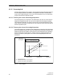
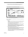
4.2.11
Alarmstrom / Alarmspannung
Über diese Funktion kann die Größe des unteren und des oberen Alarmstromes bzw.
der unteren und oberen Alarmspannung eingestellt werden. Beide signalisieren
einen Sensorfehler oder einen Hardware- / Firmwarefehler.
Die Höhe des oberen und unteren Alarmstromes / Alarmspannung sowie die obere
und untere Grenze des linearen Aussteuerbereiches sind in den vorgegebenen
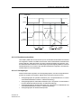
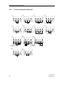
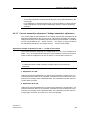
Grenzen des Stromaussteuerbereiches / Spannungsaussteuerbereiches frei wählbar. Bild 11 zeigt dies am Beispiel des 4 ... 20mA-Stromausganges.
Die spezifizierten Genauigkeiten des Ausgangssignals gelten nur für die jeweiligen
Nennbereiche.
Messbereich
1.
2.
3.
4.
5.
6.
7.
Bild 11
SITRANS TW
A5E00054075-05
linearer Aussteuerbereich
untere Grenze des Aussteuerbereichs (Defaultwert)
obere Grenze des Aussteuerbereichs (Defaultwert)
unterer Alarmstromwert (Defaultwert)
oberer Alarmstromwert (Defaultwert)
Empfohlener Einstellbereich für unteren Alarmstrombereich und untere Aussteuerungsbereichsgrenze
Empfohlener Einstellbereich für oberen Alarmstrombereich und obere Aussteuerungsbereichsgrenze
Stromgrenzen bei Ausgangssignal 4 ... 20mA
29
Funktionen / Bedienung über HART
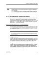
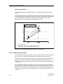
4.2.12 Sensorabgleich
Mit dem Sensorabgleich ist es möglich, die Kennlinie des angeschlossenen Sensors
an zwei Abgleichpunkten einzustellen. Die Ergebnisse sind dann korrekte Messwerte an den Abgleichpunkten. Durch einen Sensorabgleich kann der Fehleranteil
aufgrund der Kennlinie reduziert werden.
4.2.12.1 Trimmung des unteren Sensorabgleichpunktes
Die Prozessgröße (z.B. Temperatur oder Widerstand), bei dem der untere Sensorabgleich durchgeführt werden soll, wird an den Messumformereingang angelegt.
Über SIMATIC PDM oder den HART-Communicator ist dem Messumformer mitzuteilen, diesen Prozesswert zu übernehmen. Dies stellt eine Offset-Verschiebung der
Kennlinie (B, Bild 12) dar.
4.2.12.2 Trimmung des oberen Sensorabgleichpunktes
Die Prozessgröße (z.B. Temperatur oder Widerstand), bei dem der obere Sensorabgleich durchgeführt werden soll, wird an den Messumformereingang angelegt. Über
SIMATIC PDM oder den HART-Communicator ist dem Messumformer mitzuteilen,
diesen Prozesswert zu übernehmen. Hierdurch wird eine Steigungskorrektur der
Kennlinie (C, Bild 12) durchgeführt. Der untere Sensorabgleichpunkt wird nicht
beeinflusst.
gemessene
Prozessgröße
1.: A → B: Parallelverschiebung
2.: B → C: Steigungsänderung
unterer
Abgleichpunkt
oberer
Abgleichpunkt
vorgegebener
Prozesswert
A: Ausgangskennlinie
B: Kennlinie nach unterem Sensorabgleich
C: Kennlinie nach oberem Sensorabgleich
Bild 12
30
Sensorabgleich
SITRANS TW
A5E00054075-05
Funktionen / Bedienung über HART
☞
HINWEIS
− Der Sensorabgleich wird nach jeder Parametrierung des Sensortyps automa-
tisch rückgesetzt.
− In der Anschaltungsart Differenz- oder Mittelwertbildung (Kapitel 6.4, Seite 55)
kann der Sensorabgleich sowohl für Messkanal 1 als auch für Messkanal 2
durchgeführt werden.
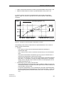
4.2.13 Stromgeberabgleich / Spannungsgeberabgleich
Der vom Messumformer ausgegebene Strom bzw. die vom Messumformer ausgegebene Spannung kann unabhängig vom Prozesskreis abgeglichen werden. Diese
Funktion ist zur Kompensation von Ungenauigkeiten in der dem Messumformer
nachgeschalteten Verarbeitungskette geeignet. Der Abgleich ist nur bei 0/4 ... 20 mA
bzw. bei 0/2 ... 10 V möglich. Bild 13, Seite 32 zeigt das Prinzip des Abgleichs am
Beispiel des 4 ... 20 mA Stromausganges.
Anwendungsbeispiel: Abgleich des 4 ... 20 mA-Stromausgangs
Der Strom soll als Spannungsabfall von 1 V bis 5 V an einem Widerstand von 250Ω
± 5 % gemessen werden. Um die Toleranz des Widerstandes auszugleichen stellen
Sie den Stromgeber so ein, dass der Spannungsabfall bei 4mA genau 1 V und bei
20 mA genau 5 V entspricht.
ACHTUNG
Ein verwendetes Multimeter muss eine höhere Klassengenauigkeit als der Messumformer aufweisen.
1. Abgleich bei 4 mA:
Über den Menüpunkt D/A-Abgleich weisen Sie den Messumformer an, 4 mA auszugeben. Auf dem Spannungsmessgerät lesen Sie den gemessenen Wert ab, errechnen daraus den Stromwert und geben diesen z.B. über SIMATIC PDM ein. Der
Messumformer verwendet diesen Wert zur Offsetkorrektur des Stromes.
2. Abgleich bei 20 mA:
Über den Menüpunkt D/A-Abgleich weisen Sie den Messumformer an, 20 mA auszugeben. Auf dem Spannungsmessgerät lesen Sie den gemessenen Wert ab,
errechnen daraus den Stromwert und geben diesen z.B. über SIMATIC PDM ein.
Der Messumformer verwendet diesen Wert zur Steigungskorrektur des Stromes. Der
Wert für 4 mA wird hierbei nicht verändert.
SITRANS TW
A5E00054075-05
31
Funktionen / Bedienung über HART
Skalierter D/A-Abgleich:
Dieser Messumformer bietet zusätzlich die Möglichkeit eines skalierten Abgleichs
des Analogausganges.
Über den Menüpunkt DA-Abgleich skaliert kann nach Eingabe der kundenspezifischen Skalierung (für oben aufgeführtes Beispiel gilt: unterer skalierter
Abgleichpunkt = 1V, oberer skalierter Abgleichpunkt = 5V) die vom Messgerät
abgelesenen Werte direkt in SIMATIC PDM bzw. in den HART-Communicator
eingetragen werden.
1.: A → B: Parallelverschiebung
2.: B → C: Steigungsänderung
A: Ausgangskennlinie
B: Kennlinie nach Stromgeberabgleich 4 mA
C: Kennlinie nach Stromgeberabgleich 20 mA
Bild 13
Stromgeberabgleich: Beispiel 4 ... 20mA-Ausgang
4.2.14 Sonderkennlinie
Der SITRANS TW bietet die Möglichkeit eine Vielzahl von Sensoren an das Gerät
anzuschließen, für die bereits eine gültige Sensorkennlinie im Gerät hinterlegt ist.
Dennoch gibt es Anwendungsfälle von Sensoren (z.B. Cu100), für die dieses Gerät
standardmäßig keine Korrektur der Nichtlinearität der Sensorkennlinie anbietet. In
diesen Fall besteht jedoch die Möglichkeit eine kundenspezifische Sonderkennlinie
im Gerät zu hinterlegen.
Für die kundenspezifische Kennlinienkorrektur benötigt das Gerät Wertepaare (XWerte, Y-Werte). Diese Wertepaare bilden Stützstellen, zwischen denen durch lineare Interpolation aus einer Eingangskennlinie die gewünschte Ausgangskennlinie
erzeugt wird. Die Anzahl der Stützstellen ist dabei abhängig von der verwendeten
Parametriersoftware.
32
SITRANS TW
A5E00054075-05
Funktionen / Bedienung über HART
•
HART-Communicator: maximale Anzahl parametrierbarer Stützstellen = 20
SIMATIC PDM: maximale Anzahl parametrierbarer Stützstellen = 50
•
Für die Sonderkennlinie ist eine kundenspezifische Einheit parametrierbar. Bild 14
zeigt das Prinzip der kundenspezifischen Kennlinienkorrektur.
Y-Werte
(Sonder)
Sonderkennlinie: Eingang: Widerstand (Dimension = Ω)
Ausgang: Sonder (Dimension = beliebig)
Wertepaare
X1, Y1
X2, Y2
X3, Y3
Lineare Interpolation
zwischen den Wertepaaren
: Paar 1
: Paar 2
: Paar 3
X9, Y9
: Paar 9
X10, Y10 : Paar 10
X-Werte
(Widerstand)
Bild 14
Prinzip kundenspezifische Kennlinienkorrektur
Bei der Parametrierung der kundenspezifischen Sonderkennlinie sind folgende Hinweise zu beachten:
•
•
SITRANS TW
A5E00054075-05
Allgemein:
− Vor Beginn der Kennlinieneingabe muss die Anzahl der Wertepaare festgelegt
werden.
− Die X-Werte müssen bei der Kennlinieneingabe monoton steigend, die YWerte monoton steigend oder monoton fallend sein.
− Die Linearisierungsart Sonderkennlinie kann nur aktiviert werden, wenn eine
gültige Sonderkennlinie im Gerät gespeichert ist.
− Wird die Linearisierungsart auf Sonderkennlinie gesetzt, so ist die DefaultKennlinieneinheit bei Widerstands-, Strom- und Spannungsmessung ´**´. Die
Defaulteinstellung kann verändert werden, doch die Messwerte werden weiterhin mit der Default-Kennlinieneinheit ´**´ angezeigt.
Kennlinieneingabe über HART-Communicator:
− Wurde die Kennlinieneingabe bereits über SIMATIC PDM vorgenommen und
mehr als 20 Wertepaare eingegeben, so sind mit dem HART-Communicator
aus dem Gerät nur die ersten 20 Wertepaare lesbar.
− Soll während der Offline-Parametrierung eine Sonderkennlinie eingegeben
werden, so sind vor Beginn der Offline-Parametrierung (Menüpunkt „3 Individuelle Bearbeitung“) im Menüpunkt „1 Alle markieren“ alle Gerätevariablen
zum „Senden“ zu aktivieren.
33
Funktionen / Bedienung über HART
4.2.15 Werkkalibrierung
Es ist möglich, die Kalibrierung des Messumformers in seinen Werksauslieferungszustand rückzusetzen. Der Umfang der wiederherstellbaren Parameter ist menügeführt über SIMATIC PDM oder den HART-Communicator in fünf Stufen zu wählen:
1. Rücksetzen der Werksgrunddaten, ausgenommen sind folgende Parameter:
→
→
→
→
kundenspezifischer Sensorabgleich
kundenspezifischer Abgleich des Analogausganges
kundenspezifische Alarmeinstellungen
kundenspezifische Einstellungen für den Sensorfehler- / Grenzwertmelder
2. Rücksetzen des kundenspezifischen Sensorabgleichs
3. Rücksetzen des kundenspezifischen Abgleichs des Analogausganges
4. Rücksetzen der kundenspezifischen Alarmeinstellungen mit folgenden Parametern:
→ Alarmtyp des Analogausganges
→ unterer und oberer Alarmwert des Analogausganges
→ unteres und oberes Ausgangslimit des Analogausganges
5. Rücksetzen der kundenspezifischen Einstellungen für den Sensorfehler- /
Grenzwertmelder mit folgenden Parametern:
→
→
→
→
→
unteres und oberes Grenzwertlimit
Hysterese
Schaltverzögerung
Grenzwertmeldermodus
Melderaktivierung
4.2.16 Diagnosefunktionen
Die Kommunikation mit einer HART-Schnittstelle ermöglicht es zahlreiche Diagnosefunktionen zu aktivieren und auszuwerten.
Das Diagnosekonzept des SITRANS TW sieht vor, dass bei Diagnosefunktionen, die
der Überwachung von Grenzwerten dienen, eine Diagnosewarnung und bei Diagnosefunktionen, die der Überwachung von Fehlerzuständen dienen, ein Diagnosealarm parametrierbar sind. Diagnosewarnung und Diagnosealarm können
ausgegeben werden über:
→
→
→
→
•
34
HART-Kommunikation
Analogausgang
Melderelais
Betriebsanzeige (LED)
Diagnosewarnung: Das Gerät übermittelt das eingetretene Diagnoseereignis
über HART. Der Analogausgangswert bleibt unverändert. Eine Warnung über
das eingebaute Melderelais (Sensorfehler- / Grenzwertmelder) ist parametrierbar.
SITRANS TW
A5E00054075-05
Funktionen / Bedienung über HART
•
Diagnosealarm: Das Gerät geht in den Zustand Alarmstrom / Alarmspannung.
Zusätzlich wird das Diagnoseereignis über HART zur Verfügung gestellt. Die
Ausgabe über das Melderelais ist parametrierbar.
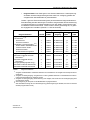
Tabelle 1 gibt eine Zusammenstellung aller parametrierbaren Diagnosefunktionen.
Standardmäßig sind alle Warnungen und Alarme ausgeschaltet. Die Parametrierung
von Diagnosewarnung und Diagnosealarm ist mit dem HART-Communicator oder
mit SIMATIC PDM vorzunehmen. Treten mehrere Fehler gleichzeitig auf, so gelten
die angegebenen Prioritäten (Priorität 1 = höchste Priorität)
Diagnosefunktion
Diagnosealarm
Sensorfehler 1) 2)
Sensorbruch
Sensorkurzschluss
Hardware-/ Firmware-Fehler 1) 3)
RAM-/ ROM-/ EEPROM-Fehler
Checksummen-Fehler
Elektronik-Fehler
Sonderkennlinie eingeben!
Diagnosewarnung
Messwert unterhalb unterem
Grenzwert 1)
Messwert überhalb oberem
Grenzwert 1)
Ausgangssättigungswarnung 1)
Messwert unterhalb Sensorlimit
Messwert überhalb Sensorlimit
Tabelle 1
1)
2)
3)
4)
5)
Priorität
Ausgabe der Diagnosefunktion über
AnalogMeldeHART
ausgang
relais 4)
LED
1
1
Status
Status
auf Alarmwert
auf Alarmwert
ja
ja
f = 1Hz
f = 1Hz
1
1
1
1
Status
Status
Status
Status
auf Alarmwert
auf Alarmwert
auf Alarmwert
auf Alarmwert
ja
ja
ja
nein
f = 1Hz
f = 1Hz
f = 1Hz
f = 1Hz
2
Status
unverändert
ja
f = 5Hz 5)
2
Status
unverändert
ja
f = 5Hz 5)
3
4
4
Status
Status
Status
unverändert
unverändert
unverändert
ja
nein
nein
f = 1Hz 5)
f = 1Hz
f = 1Hz
Diagnosefunktionen
Ausgabe auf Melderelais: wahlweises Aktivieren und Deaktivieren der Ausgabe im Menüpunkt Grenzwertmodus
Ausgabe auf Analogausgang: Ausgabe kann nur über globales Aktivieren und Deaktivieren der Bruchund Kurzschlusserkennung gesteuert werden
Ausgabe auf Analogausgang: Parametrierung nicht möglich; bei Fehler wird der Analogausgang stets
auf Alarmwert gesetzt
Zeitverzögerung für Ansprechen des Melderelais ist programmierbar
Start des Blinken erfolgt mit einer Zeitverzögerung (Zeitverzögerung ist dieselbe, die auch für das Melderelais programmiert wurde)
SITRANS TW
A5E00054075-05
35
Funktionen / Bedienung über HART
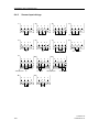
4.2.16.1 Melderelais
Mit einfachen Grenzwertbausteinen kann das Melderelais verschiedene Grenzwerte
und Fehlerzustände überwachen. Die Bausteine werden in SIMATIC PDM oder im
HART-Communicator im Menüpunkt Grenzwertmodus ein- oder ausgeschaltet. Es
sind folgende Grenzwertbausteine in allen Kombinationen parametrierbar:
a) Sensorfehlererkennung (Bruch und / oder Kurzschluss)
b) Überwachung von Hardware- und Firmwarefehlern
c) Überwachung von unterem Grenzwert
d) Überwachung von oberem Grenzwert
e) Überwachung des Analogausganges auf Sättigung
Für die Parametrierung der Grenzwertbausteine kann eine Schaltverzögerung tv des
Melderelais parametriert werden. Bei Über-/ Unterschreiten eines Grenzwertes
bewirkt diese eine Verzögerung bis der Alarm ausgelöst. Wird der Grenzwert wieder
unter- / überschritten, tritt keine Schaltverzögerung auf. Mit Hilfe der Schaltverzögerung kann eine Unterdrückung von kurzzeitigen Grenzwertüber- bzw. unterschreitungen erzielt werden. Über eine ebenfalls parametrierbare Hysterese ist ein stabiles
Meldeverhalten bei Schwankungen der Messgrößen um den Grenzwert erreichbar.
Bild 15, Seite 37 zeigt Beispiele für eine Grenzwertüberwachung.
Das Melderelais kann in die Zustände Ruhestromprinzip und Arbeitsstromprinzip
(siehe auch Kapitel 6.3, Seite 52) parametriert werden. Bei der Bedienung über den
HART-Communicator muss dabei der Parameter „Relais schließt“ wie folgt gesetzt
werden:
•
•
36
bei Ruhestromprinzip auf „EIN“
bei Arbeitsstromprinzip auf „AUS“
SITRANS TW
A5E00054075-05
Funktionen / Bedienung über HART
Melderelais
aktiv
passiv
Temperaturverlauf
oberer
Grenzwert
unterer
Grenzwert
Beispiel 1
Bild 15
Beispiel 2
Beispiel 3
Beispiele für Grenzwertüberwachung (Hysterese = 0)
4.2.16.2 Betriebsstundenzähler
Über HART (PDM oder Communicator) kann ein Betriebsstundenzähler der Elektronik ausgelesen werden. Der Zähler wird mit der ersten Inbetriebnahme des Messumformers aktiviert. Wird das Gerät von seiner Versorgungsspannung getrennt, wird
der Zählerstand automatisch im nichtflüchtigen Speicher abgelegt. Mit dem nächsten
Wiederanlauf kann es somit auf den aktuellen Zählerstand zugreifen. Der Betriebsstundenzähler ist nicht rücksetzbar.
4.2.16.3 Schleppzeiger
Dieses Gerät bietet insgesamt vier Schleppzeigerpaare, mit denen folgende Messgrößen auf negative und positive Spitzenwerte überwacht werden können:
•
•
Schleppzeigerpaar für primären Messwert (z.B. Temperaturdifferenz T1-T2 bei
zwei Widerstandsthermometern in Differenzschaltung)
Schleppzeigerpaar für sekundären Messwert (z.B. Temperatur von Messkanal 1
bei zwei Widerstandsthermometern in Differenzschaltung)
Schleppzeigerpaar für tertiären Messwert (z.B. Temperatur von Messkanal 2 bei
zwei Widerstandsthermometern in Differenzschaltung)
Schleppzeigerpaar für Elektroniktemperatur
SITRANS TW
A5E00054075-05
37
•
•
Funktionen / Bedienung über HART
Pro Messgröße speichert ein rücksetzbarer Schleppzeiger langfristig die maximalen
und minimalen Spitzenwerte im nichtflüchtigen Speicher. Damit bleiben die Werte
auch nach einem Wiederanlauf des Gerätes verfügbar. Die Schleppzeiger werden
auch während der Simulation (siehe Kapitel 4.2.18, Seite 39) aktualisiert. Bild 16
zeigt das Prinzip eines Schleppzeigerverlaufs.
oberer Schleppzeigerwert
Temperaturverlauf
unterer Schleppzeigerwert
Bild 16
Prinzipielle Darstellung von Schleppzeigern am Beispiel Temperatur
Ein Rücksetzen der Schleppzeiger erfolgt:
•
•
automatisch, nachdem ein anderer Sensortyp parametriert wurde
auf Anforderung des Anwenders
ACHTUNG
Nach Umparametrieren der Anschaltungsart und der Komplettierung der Installationsarbeiten sind die Schleppzeiger vom Kunden rückzusetzen.
38
SITRANS TW
A5E00054075-05
Funktionen / Bedienung über HART
4.2.17 Testfunktionen
Der SITRANS TW bietet folgende Testfunktionen zur Überprüfung seiner Hard- und
Firmware:
•
•
Rücksetzen der SITRANS TW-Elektronik:
Das Rücksetzen der SITRANS TW-Elektronik bewirkt ein RESET des Microcontroller, was mit einem Aus- und wieder Einschalten der Versorgungsspannung
verglichen werden kann.
Selbsttest:
Der Microcontroller führt umfangreiche Hardware- und Firmwarediagnoseroutinen aus.
4.2.18 Simulation
Mit der Diagnosefunktion „Simulation“ kann man ohne einen am Gerät anliegenden
Prozesswert (Quasi-)Messdaten empfangen und weiterverarbeiten. Einzelne Prozessabläufe können so im „kalten“ Zustand durchfahren und damit Prozesszustände
simuliert werden. Außerdem können durch Aufschalten von Simulationswerten die
Leitungsführung für den Analogausgang sowie das Melderelais geprüft werden.
Der zu simulierende Wert kann als Festwert oder in Form einer Rampenfunktion vorgegeben werden. Es sind folgende Simulationen für Messeingang und Analogausgang möglich:
Messeingang:
•
•
Festwertsimulation oder Rampensimulation für primäre Prozessgröße
Festwertsimulation oder Rampensimulation für Elektroniktemperatur
Messausgang:
•
Festwertsimulation des Analogausganges
Die Simulation von primärer Prozessgröße, Elektroniktemperatur und Analogausgang wird in Parametrierung und Funktion gleich gehandhabt, so dass im folgenden
nur die allgemeinen Simulationsverfahren „Festwert“ und „Rampenfunktion“ am Beispiel des Messeinganges erläutert werden.
Aus Sicherheitsgründen werden alle Simulationsdaten nur im Arbeitsspeicher (RAM)
gehalten. Nach einem Neustart des Gerätes ist eine evtl. eingeschaltete Simulation
wieder ausgeschaltet.
SITRANS TW
A5E00054075-05
39
Funktionen / Bedienung über HART
Messkanal 1
Messkanal 2
Messwertberechnung
T Elektronik
Messen
Simulieren
primärer
Messwert
sekundärer
Messwert
z.B.
tertiärer
Messwert
T Elektronik
Werte
I konstant
Werte primärer
Messwert
Rampe
Werte
T Elektronik
Bild 17
Festwert
Prinzipschaltbild Simulation
4.2.18.1 Allgemeine Hinweise
•
•
•
•
Solange die Simulation eingeschaltet ist, reagiert der Messumformer nicht auf
Sensoreingangssignale.
Bei Differenz- bzw. Mittelwertschaltung ist keine Simulation möglich.
Werden Thermolemente simuliert, so wird für die Simulation eine feste Vergleichsstellentemperatur von 0°C verwendet.
Die Simulation der Elektroniktemperatur hat keinen Einfluss auf den Analogausgang. Sie ist nur über die HART-Kommunikationsschnittstelle zu beobachten.
4.2.18.2 Simulation Messeingang
Simulation als Festwert
Unter Berücksichtigung der physikalischen Einheit können für beide Simulationsstrecken (primärer Messwert und Elektroniktemperatur) feste Simulationswerte parametriert werden. Der Analogausgangswert stellt sich entsprechend der Vorgabe für den
primären Messwert ein.
Simulation mit einer periodischen Rampenfunktion
Neben den einstellbaren Festwerten kann für beide Simulationswege auch je eine
periodisch wiederkehrende Rampenfunktion parametriert werden. Ein einstellbarer
Anfangs- und Endwert legt jeweils die Grenzen fest, zwischen denen sich die Simu-
40
SITRANS TW
A5E00054075-05
Funktionen / Bedienung über HART
lationswerte mit steigender und fallender Tendenz bewegen. Mit der ebenfalls einstellbaren Schrittzahl kann die Schrittweite berechnet werden.
Schrittweite =
Endwert – Anfangswert
Schrittzahl
Die Dauer zwischen zwei aufeinanderfolgenden Simulationswerten wird durch die
Schrittdauer festgelegt.
Bei der Simulation für den primären Messwert folgt der Analogausgang den simulierten Werten.
4.2.19 Parametriervarianten
4.2.19.1 „Offline-Parametrierung“
Es besteht die Möglichkeit über SIMATIC PDM oder über den HART-Communicator
eine Geräteparametrierung durchzuführen, ohne dass ein Gerät an die Bediensoftware angeschlossen werden muss. Mit dieser Art der Parametrierung („Offline-Parametrierung“) kann man geräteunabhängig Datensätze erzeugen, diese abspeichern
und in einzelne Geräte hinterlegen. Bei der „Offline-Parametrierung“ sind folgende
Hinweise zu berücksichtigen:
•
•
Beim Senden der Datensätze in das angeschlossene Gerät ist darauf zu achten,
dass dieses alle Hardware-Voraussetzungen erfüllt. (z.B. Ist ein Grenzwertmelder im Gerät vorhanden? Ist das Gerät zum Messen von Strömen geeignet?).
Wird dies nicht beachtet, so kommt es zu Parametrierfehlern.
Dieses Gerät erlaubt, bis auf den Parameter Linearisierungsart, eine „OfflineKonfiguration“ aller Geräteparameter. Die Linearisierungsart ist nur „online“
parametrierbar. Für die Linearisierungsart setzt die Gerätefirmware nach Empfang des „Offline“-Parametrierdatensatzes jedoch einen Standardwert. Bei
Bedienung des Gerätes mit SIMATIC PDM gilt diese Einschränkung nicht.
Jedoch wird hierfür die PDM-Device Description Rev. 2 benötigt.
(In SIMATIC PDM 5.2 ist die PDM-DD Rev. 2 bereits enthalten).
Für SIMATIC PDM ab V6.0 steht ein Update unter www.siemens.de/sitranst
(-> Support / -> Software Downloads) zur Verfügung.
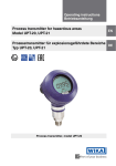
4.2.19.2 „Klonen“
Sollen viele Messumformer mit ein und den selben Parametrierdaten installiert werden, so ist das „Geräteklonen“ eine einfache Möglichkeit den Einstellaufwand zu
begrenzen.
Folgende Vorgehensweise wird beim „Geräteklonen“ empfohlen:
1. Parametrieren des Referenz-Messumformers entsprechend der gewünschten
Messaufgabe.
2. Auslesen, eventuelles Bearbeiten und Sichern des Datensatzes vom ReferenzMessumformer
3. Senden des Referenz-Datensatzes in weitere Messumformer
SITRANS TW
A5E00054075-05
41
Funktionen / Bedienung über HART
•
HART-Communicator: Besonderheit beim „Klonen“ mit Sonderkennlinie:
− Wurde vor dem Auslesen des Referenzdatensatzes eine Sonderkennlinie eingegeben, so ist vor dem Senden des Datensatzes in weitere Geräte der
HART-Communicator aus- und wieder einzuschalten.
4.3
Tipps zur HART-Communicator-Bedienung
4.3.1
Hotkey-Taste
Mit Hilfe der Hotkey-Taste F7 des HART-Communicators kann in ein kundenspezifisches Handheldmenü gewechselt werden. In diesem sind z.B. häufig genutzte Funktionen zu einer Menügruppe zusammenfassbar. Standardmäßig ist in diesem Menü
bereits die Funktion „Nullpunkt / Spanne einstellen“ enthalten. Weitere Menüpunkte
können nach Belieben hinzugefügt werden.
Eine ausführliche Beschreibung der Hotkey-Taste ist der Dokumentation zum
HART-Communicator zu entnehmen.
42
SITRANS TW
A5E00054075-05
Technische Daten
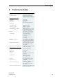
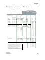
5
Technische Daten
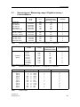
Eingang
Wählbare Filter zur Unterdrückung
von Netzfrequenzen
50 Hz, 60 Hz, zusätzlich 10 Hz
für spezielle Anwendungen
(Netzfrequenzfilter sind gleichbedeutend mit der Messfrequenz)
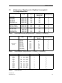
Widerstandsthermometer
Messgröße
Temperatur
Messbereich
parametrierbar
Messspanne
min. 25 °C
(45 °F) x 1/Skalierungsfaktor
Eingangstyp
• nach DIN IEC 751
Pt100 (DIN IEC 751)
• nach JIS C 1604-81
Pt100 (JIS C1604-81)
• nach DIN 43760
Ni100 (DIN 43760)
• Sondertyp (RRTD 500 )
Vielfache oder Teile der angegebenen Grundwerte sind parametrierbar (z. B. Pt500, Ni120)
Kennlinie
temperaturlinear, widerstandslinear oder kundenspezifisch
Schaltungsart
• Standardschaltung
• Summen- oder Parallelschaltung
• Mittelwert- oder Differenzschaltung
Anschluss
2-, 3- oder 4-Leiter-Schaltung
Messbereichsgrenzen
je nach angeschlossenem Thermometertyp (definierter Bereich
des Widerstandsthermometers)
Fühlerbruchüberwachung
Überwachung aller Anschlüsse
auf Leitungsbruch (Funktion
abschaltbar)
Fühlerkurzschlussüberwachung
Ansprechschwelle parametrierbar
(Funktion abschaltbar)
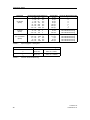
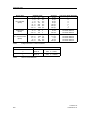
Widerstandsgeber, Potentiometer
Messgröße
Ohmscher Widerstand
Messbereich
parametrierbar
Messspanne
min. 10 Kennlinie
widerstandslinear oder kundenspezifisch
Schaltungsart
• Standardschaltung
• Differenzschaltung
• Mittelwertschaltung
Anschluss
2-, 3- oder 4-Leiter-Schaltung
Eingangsbereich
0 ... 6000 ;
bei Mittelwert- und Differenzschaltung: 0 ... 3000 Fühlerbruchüberwachung
Überwachung aller Anschlüsse
auf Leitungsbruch (Funktion
abschaltbar)
Fühlerkurzschlussüberwachung
Ansprechschwelle parametrierbar
(Funktion abschaltbar)
SITRANS TW
A5E00054075-05
43
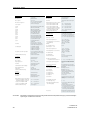
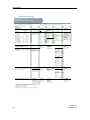
Technische Daten
A-, mA-Geber
Thermoelemente
Messgröße
Temperatur
Messgröße
Gleichspannung
Messbereich
parametrierbar
Messbereich
parametrierbar
Messspanne
min. 50 °C
(90 °F) x 1/Skalierungsfaktor
Kennlinie
stromlinear oder kundenspezifisch
Messbereichsgrenzen
je nach angeschlossenem
Thermoelementetyp
Eingangsbereich/min. Messspanne
• Geräte mit 7NG3242-xxxx4
• Geräte mit 7NG3242-xxxx5
• Geräte mit 7NG3242-xxxx6
• Geräte mit 7NG3242-xxxx7 oder
7NG3242-xxxx0 mit U/I-Stecker
• Geräte mit 7NG3242-xxxx8
Fühlerbruchüberwachung
Thermopaar
Typ B:
Pt30%Rh/Pt6%Rh (DIN IEC 584)
Typ C:
W5%-Re (ASTM 988)
W3%-Re (ASTM 988)
NiCr/CuNi (DIN IEC 584)
Typ D:
Typ E:
Typ J:
Fe/CuNi (DIN IEC 584)
NiCr/Ni (DIN IEC 584)
Fe-CuNi (DIN 43710)
Typ K:
Typ L:
Typ N:
NiCrSi-NiSi (DIN IEC 584)
Pt13%Rh/Pt (DIN IEC 584)
Pt10%Rh/Pt (DIN IEC 584)
Typ R:
Typ S:
Typ T:
Typ U:
Kennlinie
Ausgang
Ausgangssignal
Strom 0/4 ... 20 mA
-0,5 ... +23,0 mA,
stufenlos einstellbar
Sondertyp
(-10 mV UTC 100 mV)
• Ausfallsignal (bei Sensorfehler)
(gemäß NE43)
-0,5 ... +23,0 mA,
stufenlos einstellbar
• Bürde
650 • Leerlaufspannung
30 V
• Standardschaltung
• Summenschaltung
• Mittelwertschaltung
• Differenzschaltung
keine, geräteinterne Messung,
externe Messung oder vorgegebener Festwert
Fühlerbruchüberwachung
Funktion abschaltbar
mV-Geber
Messgröße
Gleichspannung
Messbereich
parametrierbar
Messspanne
min. 4 mV
Eingangsbereich
-120 ... +1000 mV
Kennlinie
spannungslinear oder
kundenspezifisch
Überlastbarkeit der Eingänge
max. ± 3,5 V
Eingangswiderstand
1 M
Fühlerstrom
etwa 180 A
Fühlerbruchüberwachung
Funktion abschaltbar
Spannung 0/2 ... 10 V
• Übersteuerungsbereich
-0,25 ... +10,75 V,
stufenlos einstellbar
• Ausfallsignal (bei Sensorfehler)
-0,25 ... +10,75 V,
stufenlos einstellbar
• Lastwiderstand
1 k
• Lastkapazität
10 nF
• Kurzschlussstrom
100 mA (nicht dauerhaft
kurzschlussfest)
• Elektrische Dämpfung
- einstellbare Zeitkonstante T63
Messgröße
Gleichspannung
Messbereich
parametrierbar
Kennlinie
spannungslinear oder
kundenspezifisch
stufenlos einstellbar innerhalb
des gesamten Aussteuerbereiches
Sensorfehler-/Grenzwertsignalisierung
durch Betriebsanzeige, Relaisausgang bzw. HART-Schnittstelle
Betriebsanzeige
• Grenzwert über-/unterschritten
• Sensorfehler
Relaisausgang
Blinksignal
Blinkfrequenz 5 Hz
Blinkfrequenz 1 Hz
wahlweise als Arbeits-/Ruhestromschaltung mit 1 Wechsler
150 W, 625 VA
DC 125 V, AC 250 V
DC 2,5 A
Signalisierung von Fühler- oder
Leitungsbruch und Fühlerkurzschluss
• Schaltleistung
• Schaltspannung
• Schaltstrom
Sensorfehler
Eingangsbereich/min. Messspanne
• Geräte mit 7NG3242-xxxx1 oder
7NG3242-xxxx0 mit U/I-Stecker
-1,2 ... +10 V/0,04 V
• Geräte mit 7NG3242-xxxx2
-12 ... +100 V/0,4 V
• Geräte mit 7NG3242-xxxx3
-120 ... +140 V/4,0 V
Fühlerbruchüberwachung
nicht möglich
0 ... 100 s, in Schritten von 0,1 s
• Stromgeber/Spannungsgeber
V-Geber
44
eingeprägter Gleichstrom
0/4 ... 20 mA, umrangierbar auf
eingeprägte Gleichspannung
0/2 ... 10 V mittels Steckbrücken
• Übersteuerungsbereich
Vergleichsstellenkompensation
ACHTUNG:
-120 ... +1000 mA/4 mA
nicht möglich
Cu/CuNi (DIN IEC 584)
Cu/CuNi (DIN 43710)
temperaturlinear, spannungslinear oder kundenspezifisch
Schaltungsart
-12 ... +100 A/0,4 A
-120 ... +1000 A/4 A
-1,2 ... +10 mA/0,04 mA
-12 ... +100 mA/0,4 mA
Grenzwertüberwachung
• Schaltverzögerung
0 ... 10 s
• Überwachungsfunktionen der
Grenzwertgruppe
• Sensorfehler (Bruch und/oder
Kurzschluss)
• unterer/oberer Grenzwert
• Fenster (Kombination von unterem und oberem Grenzwert)
• Grenzwert- und Sensorfehlererkennung sind kombinierbar
• Hysterese
beliebig parametrierbar zwischen
0 und 100 % des Messbereiches
Bei Geräten mit Explosionsschutz sind die gemäß EG-Baumusterprüfbescheinigung maximal zulässigen
Spannungen und Ströme zu beachten
SITRANS TW
A5E00054075-05
Technische Daten
Hilfsenergie
Universalnetzteil
Einsatzbedingungen
UH 115/230 V oder UH 24 V
Toleranzbereich Hilfsenergie
• bei Netzteil UH 115/230
DC 80 ... 300 V; AC 90 ... 250 V
• bei Netzteil UH 24
DC 18 ... 80 V; AC 20,4 ... 55,2 V
(jeweils unterbrechungssicher bis 20 ms im gesamten
Toleranzbereich)
Toleranzbereich Netzfrequenz
47 ... 63 Hz
Leistungsaufnahme bei
• AC 230 V
• DC 230 V
• AC 24 V
• DC 24 V
5 VA
5W
5 VA
5W
Arbeitsspannung zwischen allen
galvanisch getrennten Kreisen
Montageort (bei Geräten mit
Explosionsschutz)
• Messumformer
außerhalb des explosionsgefährdeten Bereiches
• Aufnehmer
innerhalb des explosionsgefährdeten Bereiches Zone 1 (in
Verbindung mit den vorgeschriebenen Schutzanforderungen für
den Sensor auch in Zone 0)
Umgebungsbedingungen
Zulässige Umgebungstemperatur
-25 ... +70 °C (-13 ... +158 °F)
Zulässige Lagerungstemperatur
-40 ... +85 °C (-40 ... +185 °F)
Klimaklasse
Galvanische Trennung
Galvanisch getrennte Kreise
Einbaubedingungen
Eingang, Ausgang, Hilfsenergie
und Sensorfehler-/Grenzwertmelderausgang sind voneinander
galvanisch getrennt. Die HARTSchnittstelle ist mit dem Ausgang
galvanisch verbunden.
Die Spannung Ueff zwischen zwei
beliebigen Anschlussklemmen
darf 300 V nicht überschreiten
• Relative Luftfeuchte
Gewicht
etwa 0,24 kg (0.53 lb)
Gehäusewerkstoff
PBT, glasfaserverstärkt
Schutzklasse nach IEC 529
IP20
Schutzklasse nach VDE 0100
Schutzklasse I
Montageart
Hutschiene 35 mm (1.38 inch)
(DIN EN 50022) oder G-Schiene
32 mm (1.26 inch)
(DIN EN 50035)
Elektrischer Anschluss/Prozessanschluss
Schraub-Steckverbinder,
max. 2,5 mm² (0.01 inch²)
Messgenauigkeit
Messabweichung
• Fehler der internen Vergleichsstelle
3 °C ± 0,1 °C / 10 °C
( 5.4 °F ± 0,18 °F / 18 °F)
• Fehler externe Vergleichsstellenklemme 7NG3092-8AV
0,5 °C ± 0,1 °C / 10 °C
( 0.9 °F ± 0.18 °F / 18 °F)
• digitaler Ausgang
siehe „Digitale Abweichung“
• analoger Ausgang IAN bzw. UAN
0,05 % der Messspanne zuzüglich digitale Abweichung
Einflusseffekte (bezogen auf den
digitalen Ausgang)
gegenüber der max. Messspanne:
• Temperaturdrift
0,08 %/10 °C ( 0,08 %/18 °F)
0,2 % im Bereich -10 ... +60 °C
(14 ... 140 °F)
• Langzeitdrift
0,1 % / Jahr
Einflusseffekte bezogen auf den
analogen Ausgang IAN bzw. UAN
gegenüber der Messspanne:
• Temperaturdrift
0,08 % / 10 °C ( 0,08 %/18 °F)
0,2 % im Bereich -10 ... +60 °C
(14 ... 140 °F)
• Versorgungsspannung
0,05 % / 10 V
• Bürde bei Stromausgang
0,05 % bei Änderung von 50 auf 650 • Last bei Spannungsausgang
0,1 % bei Änderung des Laststromes von 0 mA auf 10 mA
• Langzeitdrift (Messanfang, Messspanne)
0,03 % / Monat
Einstellzeit (T63 ohne elektrische
Dämpfung)
0,2 s
Elektromagnetische
Verträglichkeit
gemäß EN 61326 und
NAMUR NE21
5 ... 95 %, keine Betauung
Konstruktiver Aufbau
Parametrierschnittstelle
Protokoll
HART, Version 5.9
Bürde bei Anschluss eines
• HART-Communicators
230 ... 650 • HART-Modems
230 ... 500 Software für PC/Laptop
SIMATIC PDM ab V5.1
Zertifikate und Zulassungen
ATEX
EN 60079-0 : 2009;
EN 60079-11 : 2007;
EN 61241 : 2006
Eigensicherheit nach EN 60079-11
für 7NG3242-.A.../-.B...
II (1) G [Ex ia Ga] IIC bzw.
II (1) D [Ex ia Da] IIIC
EG-Baumusterprüfbescheinigung
TÜV 01 ATEX 1675
Weitere Zertifikate
GOST, NEPSI
SITRANS TW
A5E00054075-05
45
Technische Daten
Digitale Abweichung
Thermoelemente
Widerstandsthermometer
Messbereich
Digitale Abweichung1)
°C (°F)
°C (°F)
Typ B
0 ... +1820
(+32 ... +3308)
3 (5.4)
Typ C
0 ... +2300
(+32 ... +4172)
2 (3.6)
Typ D
0 ... +2300
(+32 ... +4172)
1 (1.8)
Typ E
-200 ... +1000
(-328 ... +1832)
1 (1.8)
Typ J
-210 ... +1200
(-346 ... +2192)
1 (1.8)
Typ K
-200 ... +1372
(-328 ... +2502)
1 (1.8)
Typ L
-200 ... +900
(-328 ... +1652)
2 (3.6)
Typ N
-200 ... +1300
(-328 ... +2372)
1 (1.8)
3,0 (5.4)
Typ R
-50 ... +1760
(-58 ... +3200)
2 (3.6)
50
0,6 (1.1)
Typ S
-50 ... +1760
(-58 ... +3200)
2 (3.6)
-200 ... +649
(-328 ... +1200)
100
0,3 (0.5)
Typ T
-200 ... +400
(-328 ... +752)
1 (1.8)
Typ U
-60 ... +250
(-76 ... +482)
50
0,3 (0.5)
-200 ... +600
(-328 ... +1112)
2 (3.6)
• Ni50
• Ni100
-60 ... +250
(-76 ... +482)
100
0,3 (0.5)
• Ni120
-60 ... +250
(-76 ... +482)
100
0,3 (0.5)
• Ni1000
-60 ... +250
(-76 ... +482)
100
0,3 (0.5)
Eingang
Messbereich
max. zul.
Leitungswiderstand
Digitale Abweichung
°C (°F)
°C (°F)
-200 ... +850
(-328 ... +1562)
20
3,0 (5.4)
• Pt50
-200 ... +850
(-328 ... +1562)
50
0,6 (1.1)
• Pt100
-200 ... +850
(-328 ... +1562)
100
0,3 (0.5)
• Pt200
-200 ... +850
(-328 ... +1562)
100
0,6 (1.1)
• Pt500
-200 ... +850
(-328 ... +1562)
100
1,0 (1.8)
• Pt1000
-200 ... +850
(-328 ... +1562)
100
1,0 (1.8)
• Pt10
-200 ... +649
(-328 ... +1200)
20
• Pt50
-200 ... +649
(-328 ... +1200)
• Pt100
DIN IEC 751
• Pt10
Eingang
JIS C 1604-81
DIN 43760
1)
Genauigkeitsangabe bezieht sich auf den größten Fehler im gesamten Messbereich
Spannungsgeber / Stromgeber
Eingang
Messbereich
Digitale Abweichung
mV-Geber (linear)
mV
V
-1 ... +16
35
-3 ... +32
20
-7 ... +65
20
Widerstandsgeber
Eingang
Widerstand
(linear)
ACHTUNG:
46
Messbereich
max. zul.
Leitungswiderstand
Digitale
Abweichung
-15 ... +131
50
-31 ... +262
100
-63 ... +525
200
0 ... 24
5
0,08
-120 ... +1000
300
0 ... 47
15
0,06
V
mV
0 ... 94
30
0,06
-1,2 ... +10
3
0 ... 188
50
0,08
-12 ... +100
30
0 ... 375
100
0,1
-120 ... +140
300
0 ... 750
100
0,2
0 ... 1500
75
1,0
-12 ... 100 A
0,05
0 ... 3000
100
1,0
-120 ... +1000 A
0,5
0 ... 6000
100
2,0
-1,2 ... +10 mA
5
-12 ... + 100 mA
50
-120 ... +1000 mA
500
V-Geber (linear)
A/mA-Geber (linear) A/mA
A
Bei Geräten mit Explosionsschutz sind die gemäß EG-Baumusterprüfbescheinigung maximal zulässigen
Spannungen und Ströme zu beachten
SITRANS TW
A5E00054075-05
Technische Daten
5.1
Fühlerarten / Messbereich / Digitale Genauigkeit /
Leitungswiderstand
Sensortyp
Messbereich
in °C
Genauigkeit
in °C
maximal zulässiger
Leitungswiderstand in Ohm
Strom für
Brucherkennung
Pt10 DIN IEC
Pt50 DIN IEC
Pt100 DIN IEC
Pt200 DIN IEC
Pt500 DIN IEC
Pt1000 DIN IEC 751
-200 bis 850
-200 bis 850
-200 bis 850
-200 bis 850
-200 bis 850
-200 bis 850
3,00
0,60
0,30
0,60
1,00
1,00
20
50
100
100
100
100
I1
I1
I1
I1
I2
I2
Pt10 JIS C 1604-81
Pt50 JIS C 1604-81
Pt100 JIS C 1604-81
-200 bis 649
-200 bis 649
-200 bis 649
3,00
0,60
0,30
20
50
100
I1
I1
I1
-60 bis 250
-60 bis 250
-60 bis 250
-60 bis 250
0,30
0,30
0,30
0,30
50
100
100
100
I1
I1
I1
I2
Ni50 DIN 43760
Ni100 DIN 43760
Ni120 DIN 43760
Ni1000 DIN 43760
Tabelle 2
Widerstandsthermometer (Leitungswiderstand = 1 x Hinleitung + 1 x Rückleitung)
Sensortyp
Widerstand
(linear)
Messbereich in
Ohm
Genauigkeit
in Ohm
maximal zulässiger
Leitungswiderstand
in Ohm
Strom für
Brucherkennung
0,08
0,06
0,06
0,08
0,10
0,20
1,00
1,00
2,00
5
15
30
50
100
100
75
100
100
I1
I1
I1
I1
I1
I1
I1
I2
I2
0 bis 24
0 bis 47
0 bis 94
0 bis 188
0 bis 375
0 bis 750
0 bis 1500
0 bis 3000
0 bis 6000*)
*) nicht bei Differenz- oder Mittelwertschaltung
Tabelle 3
Widerstandsgeber (Leitungswiderstand = 1 x Hinleitung + 1 x Rückleitung)
Sensortyp
Typ B
Typ C
Typ D
Typ E
Typ J
Typ K
Typ L
Typ N
Typ R
Typ S
Typ T
Typ U
Messbereich in °C
0
0
0
-200
-210
-200
-200
-200
-50
-50
-200
-200
bis
bis
bis
bis
bis
bis
bis
bis
bis
bis
bis
bis
1820
2300
2300
1000
1200
1372
900
1300
1760
1760
400
600
Genauigkeit in °C*)
Strom für Brucherkennung
3
2
1
1
1
1
2
1
2
2
1
2
I2
I2
I2
I2
I2
I2
I2
I2
I2
I2
I2
I2
*) Genauigkeitsangabe bezieht sich auf den größten Fehler im gesamten Messbereich
Tabelle 4
Thermoelemente
SITRANS TW
A5E00054075-05
47
Technische Daten
Sensortyp
mV-Geber
(linear)
V-Geber
(linear)
µA- / mA-Geber
(linear)
Tabelle 5
Eingestellter Eingangsbereich
-1
-3
-7
-15
-31
-63
-120
48
Strom für Brucherkennung
16
32
65
131
262
525
1000
mV
mV
mV
mV
mV
mV
mV
35
20
20
50
100
200
300
-1,2 bis
-12 bis
-120 bis
10
100
140
V
V
V
3 mV
30 mV
300 mV
keine Brucherkennung
keine Brucherkennung
keine Brucherkennung
-12
-120
-1,2
-12
-120
100
1000
10
100
1000
µA
µA
mA
mA
mA
0,05
0,5
5
50
500
keine Brucherkennung
keine Brucherkennung
keine Brucherkennung
keine Brucherkennung
keine Brucherkennung
bis
bis
bis
bis
bis
µV
µV
µV
µV
µV
µV
µV
µA
µA
µA
µA
µA
I2
I2
I2
I2
I2
I2
I2
Spannungsgeber / Stromgeber
Strom für Brucherkennung
Tabelle 6
bis
bis
bis
bis
bis
bis
bis
Genauigkeit
Grenzen für Brucherkennung
I1
I1
Bruch ein
Bruch aus
2000 bis 3100Ω
1800 bis 2700Ω
I2
I2
Bruch ein
Bruch aus
10000 bis 13000Ω
9000 bis 12000Ω
Grenzen für Brucherkennung
SITRANS TW
A5E00054075-05
Technische Daten
Maße
(1.05)
5.2
1
(4.49)
(0.47)
(5.32)
(4.43)
(1.5)
1
1
Bild 18
bei Geräten mit Explosionsschutz
Maße in mm (inch)
SITRANS TW, 4-Leiter-Tragschienengerät
SITRANS TW
A5E00054075-05
49
Technische Daten
50
SITRANS TW
A5E00054075-05
Installation und Inbetriebnahme
6
6.1
Installation und Inbetriebnahme
Montage
Die Einbaustelle soll gut zugänglich und erschütterungsfrei sein. Die zulässigen
Umgebungstemperaturen (weitere Informationen siehe Kapitel 5, Seite 43) dürfen
nicht überschritten werden. Schützen Sie den Messumformer vor Wärmestrahlung,
schnellen Temperaturschwankungen, starker Verschmutzung und mechanischer
Beschädigung.
Vor der Montage sollten Sie die gewünschten Betriebsdaten mit den auf den Typschildern des Gerätes angebrachten Werten vergleichen.
Ein Öffnen des Gehäuses ist nur zur Änderung der Hardwareeinstellungen zulässig.
Zur besseren Wärmeabfuhr ist ein Abstand von ca. 5 mm zu benachbarten Geräten
empfehlenswert.
Werden mehrere Geräte gleichzeitig in einem geschlossenen Schrank eingesetzt, so
sind die in den Fußnoten auf der Seite 47 vermerkten Hinweise und Empfehlungen
zu beachten.
WARNUNG
Es sind keine Änderungen oder Erweiterungen an den Geräten zulässig!
6.2
Einbau und Ausbau
Die Befestigung des Messumformers erfolgt wahlweise auf einer Hutschiene 35mm
(DIN EN50022) oder einer G-Schiene 32 mm (DIN EN50035). Das Gerät wird
gemäß (Bild 3, Seite 10) von der Schiene gelöst. Das Befestigungselement für den
Messumformer (Hutschienenadapter) ist abnehmbar (3, Bild 3, Seite 10). Nach Drücken der Entriegelung (4, Bild 3, Seite 10) kann das Befestigungselement seitlich
aus seiner Führung herausgeschoben werden. Es kann wahlweise in die obere oder
untere Führung am Gehäuse eingeschoben werden. Die Entriegelung (5, Bild 3,
Seite 10) muss dabei am unteren bzw. am oberen Rand des Gehäuses sein.
Der Messumformer darf nur in geschlossenen Betriebsräumen, Gehäusen und
Schränken installiert werden.
Für die Montage der Messumformer im Feld sind Feldgehäuse bzw. Schaltschränke
zu verwenden. Baugröße, Schutzart und Werkstoff sind den jeweiligen Anforderungen anzupassen.
Die in den technischen Daten (Kapitel 5, Seite 43) spezifizierten Umgebungsbedingungen sind einzuhalten.
SITRANS TW
A5E00054075-05
51
Installation und Inbetriebnahme
6.3
Elektrischer Anschluss
WARNUNG
Die Bestimmungen der für Ihr Land gültigen Prüfbescheinigung sind zu beachten.
Bei der elektrischen Installation sind die für Ihr Land gültigen nationalen Bestimmungen und Gesetze für explosionsgefährdete Bereiche zu beachten. In
Deutschland sind dies z.B.:
-
die Betriebssicherheitsverordnung
die Bestimmung über das Errichten elektrischer Anlagen in explosionsgefährdeten Bereichen DIN EN 60079-14 (früher VDE 0165)
Zwischen den Anschlüssen des eigensicheren Kreises und den nicht eigensicheren Anschlüssen muss durch Montageabstand oder Trennwände ein
Abstand von 50mm eingehalten werden (mitgeliefertes blaues Kabelgehäuse für
Eingangsstecker verwenden).
Das Potential des Eingangskreises bezogen auf den Schutzleiter muss auf 50 V
begrenzt sein, wenn das Gerät mit Netzspannung versorgt wird.
Das Gerät erfordert den Anschluss eines Schutzleiters. Bei der elektrischen Installation des Schutzleiters ist folgendes zu berücksichtigen:
- Der Schutzleiteranschluss kann bei nicht sachgemäßer Installation eine
Gefahrenquelle darstellen.
Für den Einsatz im Ex-Bereich sind beim Anschluss von Sensoren, Leitungen
und Geräten die Angaben der EG-Baumusterprüfbescheinigung zu beachten.
Insbesondere sind die Angaben für zulässige externe Kapazitäten, Induktivitäten
sowie die zulässigen Werte für Um *) zu beachten.
*) Um ist nach EN 50020 die höchste Spannung (AC oder DC), die an die nichteigensicheren
Anschlussteile angelegt werden kann, ohne die Eigensicherheit zu beeinträchtigen.
•
•
•
•
52
Der elektrische Anschluss (1-4, Bild 2, Seite 9) erfolgt über vier abziehbare
Schraub-Steckverbinder. Der maximale Leitungsquerschnitt beträgt 2,5mm². Die
Abisolierlänge darf maximal 10 mm betragen. Es ist Volldraht oder Litze mit Aderendhülse zu verwenden.
Leitungen mit berührgefährlichen Spannungen und Leitungen mit berührungefährlichen Spannungen sind getrennt voneinander zu führen oder doppelt zu isolieren.
Die Anschlussbelegung für Eingang, Ausgänge und Hilfsenergie ist in Bild 19,
Seite 53 dargestellt. Die verschiedenen Varianten für die Eingangsbeschaltung
des Sensors sind Kapitel 6.4, Seite 55 zu entnehmen.
Bei Geräten in der Ausführung „Zündschutzart Eigensicher“ ist nach Abschluss
der Installationsarbeiten das blaue Kabelgehäuse zur Zugentlastung der Eingangsleitungen fest auf dem Eingangsstecker zu montieren.
SITRANS TW
A5E00054075-05
Installation und Inbetriebnahme
•
•
•
•
•
Beim Anschluss der Hilfsenergie an Klemme 13 und 14 ist keine Polarität zu
beachten. Das Gerät ist verpolsicher.
Aus Sicherheitsgründen ist Klemme 12 mit dem Schutzleiter zu verbinden.
Der Stecker für die Hilfsenergie (Klemme 12 bis 14) darf niemals unter Spannung
gesteckt oder herausgezogen werden. Das Gerät muss durch einen in der Nähe
befindlichen und als zugehörig gekennzeichneten Netzschalter gesichert werden
Alle Schraub-Steckverbinder sind werksseitig mechanisch verwechslungssicher
kodiert (Bild 20, Seite 54). Durch die Steckerkodierung wird weiterhin gewährleistet:
− Eingangskreis: Falsches Stecken von Schraub-Steckverbinder für Ex-Stromkreise und Nicht-Ex-Stromkreise wird verhindert.
− Hilfsenergie: Falsches Stecken von Schraub-Steckverbinder mit nicht zum
Gerät passender Hilfsenergie wird verhindert.
Die spezifizierten Daten für den elektrischen Anschluss (Kapitel 5, Seite 43) sind
einzuhalten.
Netzanschluss
GWM
Sensor
Relaisausgang
1-4
5-6
7-8
9 - 11
12
13 - 14
Bild 19
: Messeingang (Beschaltungsvarianten siehe Kapitel 6.4, Seite 55)
: Analogausgang (U- oder I-Ausgang parametrierbar über Steckbrücken siehe Kapitel 3.5.3, Seite 18)
: Anschluss HART-Kommunikation zur Vor-Ort-Parametrierung
: Ausgang Sensorfehler- / Grenzwertmelder als Relaiskontakt (Parametriervarianten siehe unten bzw.
Kapitel 3.3, Seite 16)
: Schutzleiteranschluss
: Eingang Hilfsenergie (verpolsicher)
Anschlussplan Eingang, Ausgänge, Hilfsenergie
Relaisausgang:
•
•
SITRANS TW
A5E00054075-05
Ruhestromprinzip (Relais öffnet bei Fehler):
− Gerät ausgeschaltet
− Gerät eingeschaltet und kein Fehler
− Gerät eingeschaltet und Fehler
Arbeitsstromprinzip (Relais schließt bei Fehler):
− Gerät ausgeschaltet
− Gerät eingeschaltet und kein Fehler
− Gerät eingeschaltet und Fehler
: Klemme 10 und 11 verbunden
: Klemme 9 und 11 verbunden
: Klemme 10 und 11 verbunden
: Klemme 10 und 11 verbunden
: Klemme 10 und 11 verbunden
: Klemme 9 und 11 verbunden
53
Installation und Inbetriebnahme
Beispiel: 7NG3242-0Bxxx
(UH = 24V, Nicht-Ex-Gerät)
Beispiel: 7NG3242-1Axxx
(UH = 230V, Ex-Gerät)
A1
A2
B
C
D
E
F
G
H
J
K
L
Schraub-Steckverbinder für Eingang bei Nicht-Ex-Geräten
Schraub-Steckverbinder (blau) in Kabelgehäuse (blau) für Eingang bei Ex-Geräten
Schraub-Steckverbinder für Ausgang sowie für HART-Modem zur Vor-Ort-Bedienung
Schraub-Steckverbinder für Relaisausgang
Schraub-Steckverbinder für Hilfsenergie und Schutzleiteranschluss
Stiftleiste im Gerät für Eingang
Stiftleiste im Gerät für Ausgang sowie für HART-Modem zur Vor-Ort-Bedienung
Stiftleiste im Gerät für Relaisausgang
Stiftleiste im Gerät für Hilfsenergie und Schutzleiteranschluss
Kodierprofil im Schraub-Steckverbinder
Kodierreiter in Stiftleiste
Blaue Markierung des Ex-Anschlusses bei Ex-Geräten
Anmerkung: Anschlussbelegung der einzelnen Schraub-Steckverbinder siehe Bild 19, Seite 53
Bild 20
54
Kodierung der Schraub-Steckverbinder
SITRANS TW
A5E00054075-05
Installation und Inbetriebnahme
WARNUNG
Bei Geräten in der Ausführung „Zündschutzart Eigensicher“ ist vor Inbetriebnahme der Geräte sicherzustellen, dass das werksseitig mitgelieferte blaue
Kabelgehäuse auf dem Eingangsstecker fest montiert ist.
HINWEIS
Aus EMV-Gründen gilt für das Verlegen der Anschlusskabel und Signalkabel
allgemein:
-
Signalkabel getrennt von Kabeln mit Spannungen >60V verlegen.
Kabel mit verdrillten Adern verwenden.
Nähe von großen elektrischen Anlagen vermeiden, oder geschirmte Kabel
verwenden.
6.4
Sensoreingangsbeschaltung
6.4.1
Allgemeines
Folgende Informationen beziehen sich auf das Kapitel 6.4.2, Seite 56
•
•
•
Messkanal 1: Messgröße zwischen den Klemmen 2 und 3 am Eingangsstecker
Messkanal 2: Messgröße zwischen den Klemmen:
→ 3 und 4 am Eingangsstecker bei Anschaltung Nr. 4
→ 1 und 4 am Eingangsstecker bei Anschaltung Nr. 6 und Nr. 7
Bei Differenz- und Mittelwertschaltung wird die Messwertberechnung über die
Messart festgelegt. Ansonsten wird der Messwert über Messkanal 1 bestimmt.
Für die Messart wird folgende Kodierung verwendet.
Messart
Einkanalig
Differenzschaltung 1
Differenzschaltung 2
Mittelwert
•
SITRANS TW
A5E00054075-05
Messwertberechnung
Messkanal 1
Messkanal 1 – Messkanal 2
Messkanal 2 – Messkanal 1
½ x (Messkanal 1 + Messkanal 2)
Die in den Anschaltungen eingezeichneten Kurzschlussbrücken sind anlagenseitig vor Ort herzustellen.
55
Installation und Inbetriebnahme
6.4.2
Sensoreingangsbeschaltungen
1
2
4
3
2
3
4
1
3
R, RTD
2
1
2
3
+
-
2
+
-
TC
3
4
1
3
Pt100
10
4
2
1
4
1
3
2
1
R2, RTD2 R1, RTD1
8
TC
9
2
7
4
1
3
R, RTD
6
3
4
R, RTD
5
4
4
2
1
-
+ TC1
-
+ TC2
4
3
2
1
- +
-120 ... 1000mV
11
4
3
2
1
4
3
2
1
Pt100
4
-
+
U-
I+
+ -
TC
7NG3092-8AV
-1,2 ... 10V
12
7NG3092-8AW
I+
-
-12 ... 100mA
13
4
3
2
- +
56
U+
1
1
4
3
2
-
1
+
SITRANS TW
A5E00054075-05
Installation und Inbetriebnahme
Sensoreingangsbeschaltungen für Geräte mit Bestellnummer: 7NG3242-xxxx0
Widerstandsthermometer, Widerstandsgeber, Potentiometer
1
Zweileiterschaltung: Widerstand zur Leitungskompensation parametrierbar
2
Dreileiterschaltung
3
Vierleiterschaltung
4
Differenz- / Mittelwertschaltung: 2 Widerstände zur Leitungskompensation
parametrierbar
Thermoelemente
5
Ermittlung der Vergleichstemperatur mit eingebautem Pt100 oder mit fester
Referenztemperatur
6
Ermittlung der Vergleichstemperatur mit externem Pt100, Widerstand zur
Leitungskompensation programmierbar
Differenz- / Mittelwertschaltung mit interner Vergleichstemperatur
7
mV-Geber
8
Zweileiterschaltung
mit Zubehörteilen
9
Ermittlung der Vergleichstemperatur mit Vergleichsstellenklemme
7NG3092-8AV
10
Spannungsmessung -1,2 bis 10 V mit U/I-Eingangsstecker 7NG3092-8AV
11
Strommessung -12 bis 100 mA mit U/I-Eingangsstecker 7NG3092-8AW
Sensoreingangsbeschaltungen für Geräte mit Bestellnummer: 7NG3242-xxxx[1-3]
V-Geber
12
Zweileiterschaltung
Sensoreingangsbeschaltungen für Geräte mit Bestellnummer: 7NG3242-xxxx[4-8]
µA- / mA-Geber
13
Tabelle 7
6.5
Zweileiterschaltung
Sensoreingangsbeschaltungen
Inbetriebnahme
Die Software-Betriebsdaten des Messumformers müssen gemäß den Anforderungen der aktuellen Messaufgabe eingestellt sein und mit den Angaben auf dem Software-Typschild übereinstimmen. Stimmen die Software-Betriebsdaten nicht mit den
Angaben auf dem Software-Typschild überein, so ist das Typschild zu korrigieren
oder durch ein neues zu ersetzten (Kapitel 3.5.2, Seite 18).
Die Hardware-Betriebsdaten müssen ebenfalls mit den Angaben auf dem HardwareTypschild übereinstimmen. Werden Änderungen an der Hardware-Parametrierung
vorgenommen (Umschalten von Strom- auf Spannungsausgang oder umgekehrt),
so ist der aktuelle Stand auf dem Hardware-Typschild zu dokumentieren (siehe
Kapitel 3.5.3, Seite 18).
SITRANS TW
A5E00054075-05
57
Installation und Inbetriebnahme
Wird die Hilfsenergie eingeschaltet, ist der Messumformer nach ca. 5 Sekunden in
Betrieb.
WARNUNG
– Bei Geräten in der Ausführung „Zündschutzart Eigensicher“ gilt: Es dürfen nur
eigensichere Stromkreise an den Messumformereingang angeschlossen werden.
– Bei nicht sachgerechter Einspeisung ist die „Zündschutzart Eigensicher“ nicht
mehr wirksam (siehe auch Warnung auf Seite 52).
6.6
Auslieferungszustand der Betriebsdaten
Die Grundbetriebsdaten sowie die Angaben über Hardware-Optionen befinden sich
auf dem fest angebrachten Hardware-Typschild (7a, Bild 2, Seite 9) unter dem austauschbaren Software-Typschild (7, Bild 2, Seite 9).
Der Auslieferungszustand des Typschildes mit den Software-Betriebsdaten (7, Bild
2, Seite 9) richtet sich danach ob Grundgeräte oder kundenspezifisch eingestellte
Geräte bestellt werden. Der Messumformer wird je nach Bestellung folgendermaßen
geliefert:
6.6.1
Betriebsdaten gemäß werksseitigiger Grundeinstellung
(Grundgerät)
Von der Voreinstellung abweichende Betriebsdaten sind vor der Inbetriebnahme des
Messumformers vom Kunden an die jeweilige Messaufgabe anzupassen.
Ein austauschbares Blanko-Typschild (7, Bild 2, Seite 9) dient zum manuellen Eintragen der eingegebenen Betriebsdaten oder kann durch ein vom Anwender ausgedrucktes ersetzt werden.
6.6.2
Werksseitig eingestellte kundenspezifische Betriebsdaten
Das Gerät ist nach Einbau und elektrischem Anschluss für die jeweilige Messaufgabe betriebsbereit. Die eingestellten Betriebsdaten sind auf dem Software-Typschild (7, Bild 2, Seite 9) dokumentiert.
58
SITRANS TW
A5E00054075-05
Pflege und Wartung
7
Pflege und Wartung
Der Messumformer ist wartungsfrei. Eine trockene Reinigung ist zulässig.
SITRANS TW
A5E00054075-05
59
Pflege und Wartung
60
SITRANS TW
A5E00054075-05
Bestelldaten
8
Bestelldaten
Temperaturmessung
Messumformer für Tragschienenmontage
SITRANS TW
Vierleitertechnik, Universal, HART
Bestell-Nr.
Auswahl- und Bestelldaten
Universal-Messumformer SITRANS TW
} 7 NG 3 2 4 2 - 77777
für Tragschienenmontage, in 4-Leiter-Technik
(Betriebsanleitung separat bestellen)
Explosionsschutz
• Ohne
• Für Eingänge [Ex ia] bzw. [Ex ib]
}
}
Hilfsenergie
• UC 115/230 V
• UC 24 V
}
}
Ausgangssignal
• 0/4 ... 20 mA (umsteckbar auf 0/2 ... 10 V)
• 0/2 ... 10 V (umsteckbar auf 0/4 ... 20 mA)
Sensorfehler-/Grenzwertmelder
• Ohne (Nachrüstung nicht möglich)
• Relais mit Umschaltkontakt
Eingang für
• Temperaturaufnehmer, Widerstandsgeber
und mV-Geber mit Messbereich
DC -120 ... +1000 mV und mit U/I-Stecker
• Spannungseingang (V-Geber) 1)
Messbereich:
- DC -1,2 ... +10 V
- DC -12 ... +100 V (nicht Ex-Version)
- DC -120 ... +140 V (nicht Ex-Version)
• Stromeingang (A-, mA-Geber) 1)
Messbereich:
- DC -12 ... +100 A
- DC -120 ... +1000 A
- DC -1,2 ... +10 mA
- DC -12 ... +100 mA
- DC -120 ... +1000 mA
0
1
A
B
}
A
B
}
} A5E00364512
mit Dokumentation in deutsch, englisch,
französisch, spanisch, italienisch, portugiesisch und Parametriersoftware
SIPROM T
Betriebsanleitung für SITRANS TW
Deutsch/englisch
Italienisch/französisch/spanisch
} A5E00054075
} A5E00064515
Vergleichsstellenklemme
} 7NG3092-8AV
U/I-Stecker
(DC -1,2 ... +10 V bzw. -12 ... +100 mA)
} 7NG3092-8AW
siehe Kapitel 8
mit RS232-Schnittstelle
} 7MF4997-1DA
mit USB-Schnittstelle
} 7MF4997-1DB
1
2
3
4
5
6
7
8
Kurzangabe
Betriebsdaten wunschgemäß einstellen
(siehe „Liste der parametrierbaren Betriebsdaten“)
Hinweis:
im Klartext angeben: „siehe Kurzangaben“
Messstellenbeschreibung (max. 16 Zeichen)
Gerätefronttext (max. 32 Zeichen)
HART-TAG (max. 8 Zeichen)
Mit Prüfprotokoll
Mit Kurzschlussstecker zur
HART-Kommunikation bei 0 mA bzw. 0 V
Mit Stecker für externe Vergleichsstellenkompensation
Mit U/I-Stecker
(DC -1,2 ... +10 V bzw. -12 ... +100 mA)
Y01
1)
Bestell-Nr.
HART-Modem
0
Weitere Ausführungen
Bestellnummer mit „-Z“ ergänzen, Kurzangabe
hinzufügen und gegebenenfalls weitere Kurzangaben (siehe „Liste der parametrierbaren
Betriebsdaten“) angeben.
Typschildbeschriftung anstatt Deutsch
(nur in Verbindung mit Kurzangabe Y01)
• Italienisch
• Englisch
• Französisch
• Spanisch
CD für Temperaturmessgeräte
Bediensoftware SIMATIC PDM
0
1
}
Auswahl- und Bestelldaten
Zubehör
Y23
Y24
Y25
P01
S01
S02
S03
S72
S76
S77
S78
Bei Ex-Geräten Maximalwerte beachten!
} Ab Lager lieferbar.
SITRANS TW
A5E00054075-05
61
Bestelldaten
ACHTUNG
Messumformer die mit Spannungseingang (V-Geber) oder Stromeingang (µA-, mAGeber) bestellt werden, können nur in dem im Bestellschema angegebenen Messbereich eingesetzt werden. Es ist keine Sensorfehler-Überwachung möglich.
WARNUNG
Bei Messumformern mit Spannungs- oder Stromeingang und mit Explosionsschutz
sind die gemäß EG-Baumusterprüfbescheinigung maximal zulässigen Spannungen
und Ströme zu beachten.
62
SITRANS TW
A5E00054075-05
Bestelldaten
8.1
Liste der parametrierbaren Betriebsdaten
(Kurzangaben A _ _ bis K _ _)
Temperaturmessung
Messumformer für Tragschienenmontage
SITRANS TW
Vierleitertechnik, Universal, HART
■ Liste der parametrierbaren Betriebsdaten (Kurzangaben A 7 7 + B 7 7 ... E 7 7)
Bestell-Nr. mit Kurzangabe: 7NG3242 - 7 7 7 7 7 -Z Y01
Betriebsdaten gemäß Voreinstellung
Kurzangaben: A 7 7 ... E 7 7
777
+
777
777
+
+
777
+
777
Aufnehmer
Thermoelemente
Typ
Temperaturbereich
Anschaltung
B: Pt30%Rh/Pt6%Rh
C:W5%Re
D:W3%Re
E:NiCr/CuNi
J:Fe/CuNi (IEC)
K:NiCr/Ni
0 ... 1820 ºC
0 ... 2300 ºC
0 ... 2300 ºC
-200 ... +1000 ºC
-210 ... +1200 ºC
-200 ... +1372 ºC
A0
A0
A0
A0
A0
A0
0 Standard
1 Summe n 1) n = 2
2
...
3
n = 10
4 Differenz 2) Diff1
5
Diff2
B 0 1 keine
B 0 2 intern
. . . Festwert
B10
B31
B32
L: Fe/CuNi (DIN)
N:NiCrSi/NiSi
R:Pt13%Rh/Pt
S:Pt10%Rh/Pt
T:Cu/CuNi (IEC)
U:Cu/CuNi (DIN)
-200 ... +900 ºC
-200 ... +1300 ºC
-50 ... +1760 ºC
-50 ... +1760 ºC
-200 ... +400 ºC
-200 ... +600 ºC
A0
A0
A0
A0
A1
A1
6 Mittelwert 2) MW
7
8
9
0
1
B41
Widerstandsthermometer
(max. zul. Leitungswiderstände siehe
„Technische Daten“)
Pt100 (DIN IEC)
Pt100 (JIS)
Ni100 (DIN)
-200 ... +850 ºC
-200 ... +649 ºC
-60 ... +250 ºC
Widerstandsgeber, Potentiometer
Vergleichsstellenkompensation
Anschaltung
A 2 0 Standard
A 2 1 Summe n 4) n = 2
A2 2
...
n = 10
Parallel n 5) n = 0,1
n= 0,2
n= 0,5
Sonderwert 6) 7)
2)
Differenz
Diff1
Diff2
Mittelwert 2) MW
70 ºC
Sonderwert 7)
Messung extern
(über Pt100
DIN IEC 751) 7)
C00
C10
C20
C22
C25
C26
C27
Y10
Y11
Anschluss
Leitungswiderst. 3)
B 0 1 2-Leiter-Schaltung C 3 2
B 0 2 3-Leiter-Schaltung C 3 3
. . . 4-Leiter-Schaltung C 3 4
B10
B21
B22
B25
Y00
B51
B52
B61
Anschaltung
(max. zulässige Leitungswiderstände siehe A 3 0 Standard
„Technische Daten“)
Differenz 2) Diff1
Diff2
Mittelwert 2) MW
0 ºC
20 ºC
50 ºC
60 ºC
Messbereiche
Anschluss
0
D00
10 D10
20 D20
50 D50
Sonderwert 7) Y 2 0
Leitungswiderst. 3)
B 0 1 2-Leiter-Schaltung C 3 2
B 5 1 3-Leiter-Schaltung C 3 3
B 5 2 4-Leiter-Schaltung C 3 4
B61
0
10 20 50 -30 ... +60 °C
-20 ... +20 °C
0 ... 40 °C
0 ... 60 °C
0 ... 80 °C
0 ... 100 °C
0 ... 120 °C
0 ... 150 °C
0 ... 200 °C
0 ... 250 °C
0 ... 300 °C
0 ... 350 °C
0 ... 400 °C
0 ... 450 °C
0 ... 500 °C
0 ... 600 °C
0 ... 700 °C
0 ... 800 °C
0 ... 900 °C
0 ... 1000 °C
0 ... 1200 °C
0 ... 1400 °C
0 ... 1600 °C
0 ... 1800 °C
50 ... 100 °C
50 ... 150 °C
100 ... 200 °C
100 ... 300 °C
100 ... 400 °C
200 ... 300 °C
200 ... 400 °C
200 ... 500 °C
300 ... 600 °C
500 ... 1000 °C
600 ... 1200 °C
800 ... 1600 °C
Sonderbeich 7)
E00
E01
E02
E03
E04
E05
E06
E07
E08
E09
E10
E11
E12
E13
E14
E15
E16
E17
E18
E19
E20
E21
E22
E23
E24
E25
E26
E27
E28
E29
E30
E31
E32
E33
E34
E35
Y30
Messbereiche
D00
D10
D20
D50
0 ... 100 0 ... 200 0 ... 500 0 ... 1000 E40
E41
E42
E43
Sonderwert 7) Y 2 0 0 ... 2500 E44
0 ... 5000 8)
E45
0 ... 6000 8)
E46
Sonderbereich 7) Y 3 1
mV-, V-Geber sowie A-, mA-Geber 9)
1)
2)
3)
4)
5)
6)
7)
8)
9)
10)
A 4 0 Messbereich bei Bestell-Nr.
n = Anzahl der in Reihe anzuschließenden Thermoelemente
Bedeutung der Anschaltungsart siehe „Sensoreingangsbeschaltung“
Leitungswiderstand von Messkanal 1 und Messkanal 2, max. zul. Leitungswiderstand siehe „Technische Daten“ (nur bei C32, nicht bei C33 und C34)
n = Anzahl der in Reihe anzuschließenden Widerstandsthermometer
1/n = Anzahl der parallel anzuschließenden Widerstandsthermometer
Kombination aus Reihen- und Parallelschaltung der anzuschließenden
Widerstandsthermometer
Betriebsdaten, siehe „Betriebsdaten für Sonderangaben“
Dieser Bereich gilt nicht bei Mittelwertbildung und Differenzschaltung
Bei Geräten mit Explosionsschutz sind die gemäß EG Baumusterprüfbescheinigung max. zulässigen Ströme und Spannungen zu beachten.
Ohne Leitungsbrucherkennung
SITRANS TW
A5E00054075-05
E50
7NG 3242 - 7 7 7 7 7 -Z Y01
0
1
2
3
-120 ... +1000 mV
-1,2 ... +10 V 10)
-12 ... +100 V 10)
-120 ... +140 V 10)
4
5
6
7
8
-12 ... +100 A 10)
-120 ... +1000 A 10)
-1,2 ... +10 mA 10)
-12 ... +100 mA 10)
-120 ... +1000 mA 10)
Sonderbereich 7) Y 3 2
63
Bestelldaten
©Se e s G 0
Temperaturmessung
Messumformer für Tragschienenmontage
SITRANS TW
Vierleitertechnik, Universal, HART
■ Liste der parametrierbaren Betriebsdaten (Kurzangaben F 7 7 ... K 7 7)
Bestell-Nr. mit Kurzangabe: 7NG3242 - 7 7 7 7 7 -Z Y01
Betriebsdaten gemäß Voreinstellung
Kurzangaben: F 7 7 ... K 7 7
777
+
777
+
777
+
777
+
777
777
+
Aufnehmer
Thermoelemente
Typ
Temperaturbereich
B: Pt30%Rh/
C:W5%Re
D:W3%Re
E:NiCr/CuNi
J:Fe/CuNi (IEC)
K:NiCr/Ni
0 ... 1820 ºC
0 ... 2300 ºC
0 ... 2300 ºC
-200 ... +1000 ºC
-210 ... +1200 ºC
-200 ... +1372 ºC
A0
A0
A0
A0
A0
A0
0
1
2
3
4
5
L: Fe/CuNi (DIN)
N:NiCrSi/NiSi
R:Pt13%Rh/Pt
S:Pt10%Rh/Pt
T:Cu/CuNi (IEC)
U:Cu/CuNi (DIN)
-200 ... +900 ºC
-200 ... +1300 ºC
-50 ... +1760 ºC
-50 ... +1760 ºC
-200 ... +400 ºC
-200 ... +600 ºC
A0
A0
A0
A0
A1
A1
6
7
8
9
0
1
Widerstandsthermometer
(max. zul. Leitungswiderstände siehe
„Technische Daten“)
Pt100 (DIN IEC)
Pt100 (JIS)
Ni100 (DIN)
-200 ... +850 ºC
-200 ... +649 ºC
-60 ... +250 ºC
Kennlinie
Filterzeit 1)
temperatur- F 0 0
linear
spannungs- F 1 0
linear
0s
0,1 s
0,2 s
0,5 s
1s
2s
G0
G0
G0
G0
G0
G0
0
1
2
3
4
5
5s
10 s
20 s
50 s
100 s
Sonderzeit5)
G0
G0
G0
G0
G1
Y5
6
7
8
9
0
0
Filterzeit 1)
Wie bei
ThermoeleA 2 0 temperatur- F 0 0 mente
A 2 1 linear
Kennlinie
Ausgangssignal u.
Netzfilter 2)
Ausfallsignal
Grenzwertmelder 3)
GrenzwertK00
überachung
unwirksam
aufsteuernd
J 0 0 (jedoch Senzusteuernd
J 0 1 sorfehlersignaletzten Wert
J 0 2 lisierung mit
Ruhestromhalten
0 ... 20 mA /
prinzip)
0 ... 10 V
keine ÜberJ03
mit Netzfilter:
wachung
wirksam 5)
Y70
50 Hz
H 1 0 Sicherheitswert 5) Y 6 0
60 Hz
H1 1
10 Hz
H1 2
4 ... 20 mA /
2 ... 10 V
mit Netzfilter:
50 Hz
H0 0
60 Hz
H0 1
10 Hz 4)
H0 2
bei Leitungsbruch/Fehler:
Ausgangssignal u.
Netzfilter 2)
Wie bei Thermoelemente
Ausfallsignal
A 2 2 widerstands- F 2 0
linear
Grenzwertmelder 3)
Wie bei Thermoelemente
bei Leitungsbruch/Fehler:
aufsteuernd
J0
zusteuernd
J0
letzten Wert
J0
halten
keine Überwa- J 0
chung
Sicherheitswert 5) Y 6
bei Leitungsbruch oder Kurzschluss/Fehler:
aufsteuernd
J1
zusteuernd
J1
letzten Wert
J1
halten
keine Überwa- J 1
chung
Sicherheitswert 5) Y 6
Widerstandsgeber, Potentiometer
(max. zulässige Leitungswiderstände
siehe „Technische Daten“)
Filterzeit 1)
A 3 0 widerstands- F 2 0 Wie bei
Thermoelelinear
mente
Kennlinie
Ausgangssignal u.
Netzfilter 2)
Wie bei Thermoelemente
1)
2)
3)
4)
5)
64
Filterzeit 1)
aufnehmer- F 3 0 Wie bei
Thermoeleproportional
mente
A 4 0 Kennlinie
Ausgangssignal u.
Netzfilter 2)
Wie bei Thermoelemente
3
0
0
1
2
3
1
Ausfallsignal
bei Leitungsbruch/Fehler:
aufsteuernd
zusteuernd
letzten Wert
halten
J00
J01
J02
keine Überwachung
J03
Sicherheitswert 5) Y
mV-, V-Geber sowie A-, mA-Geber
0
1
2
Grenzwertmelder 3)
Wie bei Thermoelemente
60
Grenzwertmelder 3)
Wie bei Thermoelemente
Softwarefilter zur Glättung des Messergebnisses
Filter zur Unterdrückung von Netzstörungen auf dem Messsignal
falls Melderelais vorhanden
für spezielle Anwendungen
Betriebsdaten, siehe „Betriebsdaten für Sonderangaben“
SITRANS TW
A5E00054075-05
Bestelldaten
8.1.1
Liste der Betriebsdaten, Sonderbereiche
Temperaturmessung
Messumformer für Tragschienenmontage
SITRANS TW
Vierleitertechnik, Universal, HART
■ Betriebsdaten für Sonderangaben
Kurzangabe
Erforderlicher
Klartext
Möglichkeiten
Y00
N=,
Faktor N zur Multiplikation mit der
Grundreihe von Widerstandsthermometern
Wertebereich: 0,10 bis 10,00
1. Beispiel: 3 x Pt500 parallel:
N = 5/3 = 1,667;
2. Beispiel: Ni120: N = 1,2
Y10
TV=,
Temperatur TV der festen
Vergleichsstellentemperatur
D=
Einheit; Wertebereich: C, K, F, R
Y11
RL=,
Leitungswiderstand RL in zur Kompensation der Vergleichsstellenleitung des
externen Pt100 DIN IEC 751
Wertebereich: 0,00 bis 100,00
Y20
RL1=,
RL2=,
Leitungswiderstände RL von Messkanal 1
(RL1) und Messkanal 2 (RL2) in , wenn
das Widerstandsthermometer bzw. der
Widerstandsgeber in Zweileiterschaltung
geschaltet ist
Wertebereich je nach Sensortyp:
0,00 bis 100,00
Y30
MA=,
ME=,
Messanfang MA bzw. Messende ME für
Thermoelemente bzw. Widerstandsthermometer
(Wertebereich je nach Sensortyp)
D=
Einheit (Wertebereich: C, K, F, R)
Y31
MA=,
ME=,
Messanfang MA bzw. Messende ME für
Widerstandsgeber bzw. Potentiometer in Wertebereich: 0,00 bis 6000,00
Y32
MA=,
ME=,
Messanfang MA bzw. Messende ME für
mV-, V-, μA- bzw. mA-Geber
Wertebereich je nach Sensortyp:
-120,00 bis 1000,00
D=
Einheit (mV als MV angeben, V als V,
μA als UA, mA als MA)
T63=,
Einstellzeit T63 des Softwarefilters in s
Wertebereich: 0,0 bis 100,0
Y50
Sicherheitswert S des Messausganges in
mA bzw. in V entsprechend der eingestellten Ausgangsart. Wertebereich
bei Stromausgang: -0,50 bis 23,00
bei Spannungsausgang: -0,25 bis 10,75
Y60
S= ,
Sicherheitswert S bei Leitungsbruch des
Sensors
Y61
S=,
Sicherheitswert S bei Leitungsbruch oder
Kurzschluss des Sensors
Y70
UG=,
unterer Grenzwert (Einheit wie durch
Messbereich vorgegeben)
OG=,
oberer Grenzwert (Einheit wie durch Messbereich vorgegeben)
SITRANS TW
A5E00054075-05
H=,
Hysterese (Einheit wie durch Messbereich
vorgegeben)
K=
Kombination aus Grenzwertfunktion und
eingestellter Sensorfehlererkennung ein/ausschalten; J=ein; N=aus (Standard: J)
A=
Relaisausgangstyp: A=Arbeitsstromprinzip; R=Ruhestromprinzip (Standard: R)
T=,
Schaltverzögerung T des Relaisausganges in s
Wertebereich: 0,0 bis 10,0 (Standard: 0,0)
65
Bestelldaten
8.2
Ersatzteile
Benennung
Bestellnummer
für Geräte in Ex- und Nicht-Ex-Ausführung
1 x Gehäusebefestigungselement
7NG3092-8AG
1 x Klarsichtabdeckung für Typschild
7NG3092-8AN
1 x Schraub-Steckverbinder 3-polig (Klemmen 9 – 11)
7NG3092-8AR
1 x Schraub-Steckverbinder 3-polig (Klemmen 12 – 14)
7NG3092-8AA
1 x Schraub-Steckverbinder 4-polig (Klemmen 5 – 8)
7NG3092-8AB
25 x Steckbrücke 2-polig zur Auswahl der Art des Ausgangssignals bzw. für
7NG3092-8AH
HART-Schreibschutz
1 x Kurzschlussstecker für Stromprüfbuchse
7NG3092-8AP
1 x Kodierprofil für Schraub-Steckverbinder für 6 Kodierstellen
7NG3092-8AJ
1 x Kodierreiter für Stiftleiste für 6 Kodierstellen
7NG3092-8AK
12 x Blindstück für Stiftleiste
7NG3092-8AL
für Geräte in Ex-Ausführung
1 x Gehäuse-Front (Ex)
7NG3092-8AE
1 x Schraub-Steckverbinder 4-polig (Farbe blau, Klemmen 1 – 4)
7NG3092-8AC
1 x Kabelgehäuse für Schraub-Steckverbinder 4-polig (Farbe blau)
7NG3092-8AF
für Geräte in Nicht-Ex-Ausführung
66
1 x Gehäuse-Tubus (nicht Ex)
7NG3092-8AM
1 x Gehäuse-Front (nicht Ex)
7NG3092-8AD
1 x Schraub-Steckverbinder 4-polig (Farbe grau, Klemmen 1 – 4)
7NG3092-8AS
SITRANS TW
A5E00054075-05
Zertifikate
9
Zertifikate
Die Zertifikate sowie die EG-Baumusterprüfbescheinigung finden Sie auf der
separat bestellbaren CD "SITRANS T - Temperature transmitters",
Bestellnummer A5E00364512 und im Internet:
www.siemens.com/processinstrumentation/certificates
SITRANS TW
A5E00054075-05
67
Zertifikate
68
SITRANS TW
A5E00054075-05
Anhang
10 Anhang
HART Communicator, HART Rev. 5.9
Online-Bedienstruktur am Beispiel: Widerstandsthermometer, Standardschaltung, 2-Leiter-Anschluss, 4 ... 20mA-Ausgang
*) Anzeige der Messwerte
2 Online
1 MW *)
2 Konfigurieren
1 Prozeßvariablen *)
2 Diagnose/Service
1
2
3
4
1
MW
% MB
Offset1
AAusg
Diagnose
1 Schleppzeiger
1 Schleppz. Eingang
2 Schleppz. El Temp
2 Betr.St.Zähler El
3 Status
1
2
3
4
5
6
7
1 El Temp max
2 El Temp min
3 Rücksetzen
1 Summen-Status
3 Hardw/Firmw-Status
4 Diag Warn-Status
5 Simulation-Status
1 Simulation
1 Analogausgang
2 Eingänge
1 Max (PV&S1&S2)
2 Min (PV&S1&S2)
3 Min&Max (PV&S1&S2)
1 Max
2 Min
3 Max&Min
Sensor-Fehler
Hardw/Firmw-Fehl
Diagnosewarnung
Simulationsmodus
Sensorbruch
Sensorkurzschluß
2 Sensor-Status
2 Simulation/Test
Eingang max
Eingang min
Eingang S1 max
Eingang S1 min
Eingang S2 max
Eingang S2 min
Rücksetzen
1
2
3
4
1
Sensor Simu
El Temp Simu
4 mA
20 mA
Anderer Wert
Ende
Eingang
2 El Temp
1
2
3
1
2
3
Eingang FEST
Eingang RAMPE
Eingang AUS
El Temp FEST
El Temp RAMPE
El Temp AUS
3 Anzeige Prozeßvar.
4 Alle Simus AUS
2 Test
3 Grenzwertmelder
4 Ueberwachen
5 Messen L-Widerst
6 Abgleich
1
2
3
4
5
Unt Limit
Ob Limit
Hysterese
Schaltverzöger.
Grenzwertmodus
6
1
2
3
Melder-Aktivierung
Grenze
Sensorschluß 1
Sensorbruch 1
1 Sensorabgleich
2 Anl Ausg Abgleich
7 Reset Werksparam
8 Alle Meßwerte
3 Kurz-Setup
1 Auto Setup
2 Linearis.art
3 Einheit
4 Npkt/Spanne einst.
1
2
3
4
5
1
2
3
1 Selbsttest
2 Rücksetzen
Sensorfehler
HW/Firmw-Fehler
MW<Unt Grenzwert
MW>Ob Grenzwert
AAusg-Sätt.-Warn
Schaltverzöger.
Relais schließt
Grenzwertmelder
1
2
1
2
Unt Sensorabgleich
Ob Sensorabgleich
D/A Abgl
D/A Abgl skaliert
Werkseinstellung
Sensorabgleich
DAU- Abgleich
Alarme
GW-Melder
MW
El Temp
AAusg
1 Linear z.Eingang
2 Linear Temperatur
°C
°F
°Rk
K
1 MA
2 ME
3 USL
4 OSL
5 Kleinste Spanne
6 Prozeßvorgabe
1 4 mA
2 20 mA
3 Verlassen
5 Dämpfung
6 Meß-Kennz. (TAG)
SITRANS TW
A5E00054075-05
69
Anhang
2 Online
1 Meßwert
2 Konfigurieren
4 Komplett-Setup
1 Sensorparameter
1 Prozeßsensor
1 Offset Sensor 1
2 Sensor Setup
1 HINWEIS>>
2 Sensorklasse
3 Sensortyp
4 Einheit
5 Anschaltung
6 Sensorverbindung
3 Sensorinformation
2 Signalparameter
2 El Temp Sensor
1 Prozeßvariablen
2 Npkt/Spanne einst.
3 Dämpfung
4 Linearis.art
5 Sonderkennlinie
6 Meßfrequenz
3 Ausgangsparameter 1 Analogausgang
1
1
2
3
4
1
2
3
4
5
6
El Temp
MW
% MB
Offset 1
AAusg
MA
ME
USL
ODL
Kleinste Spanne
Prozeßvorgabe
Linear z.Eingang
Linear Temperatur
1 Eingabe Kennlinie
2 Anzeige Kennlinie
50 Hz
60 Hz
10 Hz
1 AAusg
2 % MB
3 Alarme
7
8
9
1
2
3
4
5
6
7
Widerst-Geber
Widerst-Thermom
mV-Geber
Thermoelement
Pt100, a=385
Pt100, a=392
Ni100
Sonder WiderstTher
°C
°F
°Rk
K
Standardschaltung
Differenz(S1-S2)
Differenz(S2-S1)
Mittelwert
Zwei-Leiter
Drei-Leiter
Vier-Leiter
Skalierungsfaktor
Leit.Widerstand 1
Messen L-Widerst
Sensorklasse
Sensorverbindung
Anschaltung
Sensortyp
USL
OSL
Kleinste Spanne
4 mA
20 mA
Verlassen
1 AAusg-Alarm-Typ
Oben
Unten
Letzten Wert halten
2 Unt Alarmwert
3 Ob Alarmwert
4 Unt AAusg.Limit
5 Ob AAusg.Limit
6 AAusg-Typ
7 AAusg-Modus
2 HART Ausgang
4 Geräteinformation
1
2
3
4
5
6
7
8
9
Meß-Kennz. (TAG)
Hersteller
Modell
Akt Bestell-Nr
Geräte-Serien-Nr
MM/TT/JJ
Schreibschutz
Beschreibung
Nachricht
Montage-Nr
Explosionsschutz
Hilfsenergie
Revisionsnummern
mA
Volt
4..20 mA
0..20 mA
1 Aufrufadresse
2 Anz Aufruf-Präam
3 Anz Antwort-Präam
1
2
3
4
Universal Rev.
Feldgeräte Rev.
Software Rev.
Hardware Rev.
5 Überblick
70
SITRANS TW
A5E00054075-05
Anhang
10.1 $Technische
Unterstützung
7HFKQLVFKH8QWHUVW¾W]XQJ
7HFKQLFDO6XSSRUW
6LHHUUHLFKHQGHQ7HFKQLFDO6XSSRUWI¾UDOOH,$XQG'73URGXNWH
Ⴠ EHUGDV,QWHUQHWPLWGHP6
6XSSRUW5HTXHVW
6XSSRUWUHTXHVWKWWSZZZVLHPHQVGHDXWRPDWLRQVXSSRUWUHTXHVW
Ⴠ (PDLOPDLOWRVXSSRUWDXWRPDWLRQ#VLHPHQVFRP
Ⴠ 7HOHIRQ
Ⴠ )D[
:HLWHUH,QIRUPDWLRQHQ]XXQVHUHP7HFKQLFDO6XSSRUWILQGHQ6LHLP,QWHUQHWXQWHU
7HFKQLFDOVXSSRUWKWWSZZZVLHPHQVGHDXWRPDWLRQFVLVHUYLFH
6HUYLFH6XSSRUWLP,QWHUQHW
=XV¦W]OLFK]XXQVHUHP'RNXPHQWDWLRQV$QJHERWELHWHQZLU,KQHQLP,QWHUQHWXQVHU
NRPSOHWWHV:LVVHQRQOLQHDQ
6HUYLFHV6XSSRUWKWWSZZZVLHPHQVGHDXWRPDWLRQVHUYLFHVXSSRUW
'RUWILQGHQ6LH
Ⴠ $NWXHOOH3URGXNW,QIRUPDWLRQHQ)$4V'RZQORDGV7LSSVXQG7ULFNV
Ⴠ 'HU1HZVOHWWHUYHUVRUJW6LHVW¦QGLJPLWGHQDNWXHOOVWHQ,QIRUPDWLRQHQ]X,KUHQ
3URGXNWHQ
Ⴠ 'HU.QRZOHGJH0DQDJHUILQGHWGLHULFKWLJHQ'RNXPHQWHI¾U6LH
Ⴠ ,P)RUXPWDXVFKHQ$QZHQGHUXQG6SH]LDOLVWHQZHOWZHLW,KUH(UIDKUXQJHQDXV
Ⴠ )LQGHQ6LH,KUHQ$QVSUHFKSDUWQHUI¾U,QGXVWU\$XWRPDWLRQXQG'ULYH7HFKQRORJLHVYRU
2UW¾EHUXQVHUH$QVSUHFKSDUWQHU'DWHQEDQN
Ⴠ ,QIRUPDWLRQHQ¾EHU9RU2UW6HUYLFH5HSDUDWXUHQ(UVDW]WHLOHXQGYLHOHVPHKUVWHKWI¾U
6LHXQWHUGHP%HUJULII/HLVWXQJHQEHUHLW
:HLWHUH8QWHUVW¾W]XQJ
%HL)UDJHQ]XU1XW]XQJGHULP+DQGEXFKEHVFKULHEHQHQ3URGXNWHGLH6LHKLHUQLFKW
EHDQWZRUWHWILQGHQZHQGHQ6LHVLFKELWWHDQ,KUHQ6LHPHQV$QVSUHFKSDUWQHULQGHQI¾U6LH
]XVW¦QGLJHQ9HUWUHWXQJHQXQG*HVFK¦IWVVWHOOHQ
,KUHQ$QVSUHFKSDUWQHUILQGHQ6LHXQWHU
3DUWQHUKWWSZZZDXWRPDWLRQVLHPHQVFRPSDUWQHU
'HQ:HJZHLVHU]XP$QJHERWDQWHFKQLVFKHQ'RNXPHQWDWLRQHQI¾UGLHHLQ]HOQHQ3URGXNWH
XQG6\VWHPHILQGHQ6LHXQWHU
$QOHLWXQJHQXQG+DQGE¾FKHU
KWWSZZZVLHPHQVGHSUR]HVVLQVWUXPHQWLHUXQJGRNXPHQWDWLRQ
SITRANS TW
A5E00054075-05
71
Anhang
72
SITRANS TW
A5E00054075-05
Contents
1 Technical Description. . . . . . . . . . . . . . . . . . . . . . . . . . . . . . . . . . . . . . . . . . .81
1.1 Application Range . . . . . . . . . . . . . . . . . . . . . . . . . . . . . . . . . . . . . . . . . . . . . . . . . . . . .
1.2 Product features . . . . . . . . . . . . . . . . . . . . . . . . . . . . . . . . . . . . . . . . . . . . . . . . . . . . . .
1.3 Design and functional principle . . . . . . . . . . . . . . . . . . . . . . . . . . . . . . . . . . . . . . . . . . .
1.3.1 Design. . . . . . . . . . . . . . . . . . . . . . . . . . . . . . . . . . . . . . . . . . . . . . . . . . . . . . . . . . .
1.3.2 Hardware rating plate . . . . . . . . . . . . . . . . . . . . . . . . . . . . . . . . . . . . . . . . . . . . . . .
1.3.3 Function principle . . . . . . . . . . . . . . . . . . . . . . . . . . . . . . . . . . . . . . . . . . . . . . . . . .
81
82
83
83
85
85
2 System integration . . . . . . . . . . . . . . . . . . . . . . . . . . . . . . . . . . . . . . . . . . . . .87
2.1 System configuration . . . . . . . . . . . . . . . . . . . . . . . . . . . . . . . . . . . . . . . . . . . . . . . . . . . 87
2.2 Operating software SIMATIC PDM . . . . . . . . . . . . . . . . . . . . . . . . . . . . . . . . . . . . . . . . 88
3 Hardware functions . . . . . . . . . . . . . . . . . . . . . . . . . . . . . . . . . . . . . . . . . . . .89
3.1 Operating display. . . . . . . . . . . . . . . . . . . . . . . . . . . . . . . . . . . . . . . . . . . . . . . . . . . . . .
3.2 Test jack for output signal . . . . . . . . . . . . . . . . . . . . . . . . . . . . . . . . . . . . . . . . . . . . . . .
3.3 Sensor error / limit value alarm . . . . . . . . . . . . . . . . . . . . . . . . . . . . . . . . . . . . . . . . . . .
3.4 Connection HART communication. . . . . . . . . . . . . . . . . . . . . . . . . . . . . . . . . . . . . . . . .
3.5 Hardware modification . . . . . . . . . . . . . . . . . . . . . . . . . . . . . . . . . . . . . . . . . . . . . . . . . .
3.5.1 Opening and closing the transmitter . . . . . . . . . . . . . . . . . . . . . . . . . . . . . . . . . . . .
3.5.2 Removing and inserting the rating plate . . . . . . . . . . . . . . . . . . . . . . . . . . . . . . . . .
3.5.3 Switching over current output to voltage output . . . . . . . . . . . . . . . . . . . . . . . . . . .
3.5.4 HART write protection. . . . . . . . . . . . . . . . . . . . . . . . . . . . . . . . . . . . . . . . . . . . . . .
3.6 External reference point compensation with reference point terminal 7NG3092-8AV. .
3.6.1 Application and use . . . . . . . . . . . . . . . . . . . . . . . . . . . . . . . . . . . . . . . . . . . . . . . .
3.6.2 Connection and wiring . . . . . . . . . . . . . . . . . . . . . . . . . . . . . . . . . . . . . . . . . . . . . .
3.6.3 Software parameterization . . . . . . . . . . . . . . . . . . . . . . . . . . . . . . . . . . . . . . . . . . .
3.6.4 Order. . . . . . . . . . . . . . . . . . . . . . . . . . . . . . . . . . . . . . . . . . . . . . . . . . . . . . . . . . . .
3.7 Current/voltage measurement by U/I input plug 7NG3092-8AW. . . . . . . . . . . . . . . . . .
3.7.1 Application and use . . . . . . . . . . . . . . . . . . . . . . . . . . . . . . . . . . . . . . . . . . . . . . . .
3.7.2 Connection and wiring . . . . . . . . . . . . . . . . . . . . . . . . . . . . . . . . . . . . . . . . . . . . . .
3.7.3 Internal structure. . . . . . . . . . . . . . . . . . . . . . . . . . . . . . . . . . . . . . . . . . . . . . . . . . .
3.7.4 Software parameterization . . . . . . . . . . . . . . . . . . . . . . . . . . . . . . . . . . . . . . . . . . .
3.7.5 Order. . . . . . . . . . . . . . . . . . . . . . . . . . . . . . . . . . . . . . . . . . . . . . . . . . . . . . . . . . . .
89
89
90
90
91
91
92
92
93
94
94
94
95
95
95
95
96
96
97
98
4 Functions / Operation by HART . . . . . . . . . . . . . . . . . . . . . . . . . . . . . . . . . . .99
4.1 Operating data . . . . . . . . . . . . . . . . . . . . . . . . . . . . . . . . . . . . . . . . . . . . . . . . . . . . . . . . 99
4.2 Parameterizable functions . . . . . . . . . . . . . . . . . . . . . . . . . . . . . . . . . . . . . . . . . . . . . . 101
4.2.1 Line break monitoring and short-circuit testing . . . . . . . . . . . . . . . . . . . . . . . . . . . 101
4.2.2 Adjusting line resistances . . . . . . . . . . . . . . . . . . . . . . . . . . . . . . . . . . . . . . . . . . . 101
4.2.3 Measuring line resistances . . . . . . . . . . . . . . . . . . . . . . . . . . . . . . . . . . . . . . . . . . 101
4.2.4 Measured value offset . . . . . . . . . . . . . . . . . . . . . . . . . . . . . . . . . . . . . . . . . . . . . 101
4.2.5 Scaling factor . . . . . . . . . . . . . . . . . . . . . . . . . . . . . . . . . . . . . . . . . . . . . . . . . . . . 101
4.2.6 Reference selection for measuring by means of a thermocouple. . . . . . . . . . . . . 102
4.2.7 Difference circuit / average value circuit . . . . . . . . . . . . . . . . . . . . . . . . . . . . . . . . 102
4.2.8 Mains frequency filter / measuring frequency . . . . . . . . . . . . . . . . . . . . . . . . . . . . 102
4.2.9 Electric damping . . . . . . . . . . . . . . . . . . . . . . . . . . . . . . . . . . . . . . . . . . . . . . . . . . 102
SITRANS TW
A5E00054075-05
75
4.2.10 Current transmitter / voltage transmitter . . . . . . . . . . . . . . . . . . . . . . . . . . . . . . .
4.2.11 Alarm current / alarm voltage . . . . . . . . . . . . . . . . . . . . . . . . . . . . . . . . . . . . . . .
4.2.12 Sensor adjustment . . . . . . . . . . . . . . . . . . . . . . . . . . . . . . . . . . . . . . . . . . . . . . .
4.2.13 Current transmitter adjustment / Voltage transmitter adjustment . . . . . . . . . . . .
4.2.14 Special characteristic . . . . . . . . . . . . . . . . . . . . . . . . . . . . . . . . . . . . . . . . . . . . .
4.2.15 Factory calibration . . . . . . . . . . . . . . . . . . . . . . . . . . . . . . . . . . . . . . . . . . . . . . .
4.2.16 Diagnostic functions . . . . . . . . . . . . . . . . . . . . . . . . . . . . . . . . . . . . . . . . . . . . . .
4.2.17 Test functions . . . . . . . . . . . . . . . . . . . . . . . . . . . . . . . . . . . . . . . . . . . . . . . . . . .
4.2.18 Simulation . . . . . . . . . . . . . . . . . . . . . . . . . . . . . . . . . . . . . . . . . . . . . . . . . . . . . .
4.2.19 Parameterization behavior . . . . . . . . . . . . . . . . . . . . . . . . . . . . . . . . . . . . . . . . .
4.3 Tips for HART communicator operation . . . . . . . . . . . . . . . . . . . . . . . . . . . . . . . . . . .
4.3.1 Hotkey. . . . . . . . . . . . . . . . . . . . . . . . . . . . . . . . . . . . . . . . . . . . . . . . . . . . . . . . . .
103
103
104
105
106
108
108
113
113
115
116
116
5 Technical data . . . . . . . . . . . . . . . . . . . . . . . . . . . . . . . . . . . . . . . . . . . . . . .117
5.1 Sensor types / Measuring range / Digital accuracy / Line resistance . . . . . . . . . . . . . 121
5.2 Dimensions . . . . . . . . . . . . . . . . . . . . . . . . . . . . . . . . . . . . . . . . . . . . . . . . . . . . . . . . . 123
6 Installation and commissioning . . . . . . . . . . . . . . . . . . . . . . . . . . . . . . . . . .125
6.1 Assembly . . . . . . . . . . . . . . . . . . . . . . . . . . . . . . . . . . . . . . . . . . . . . . . . . . . . . . . . . . .
6.2 Installation and removal. . . . . . . . . . . . . . . . . . . . . . . . . . . . . . . . . . . . . . . . . . . . . . . .
6.3 Electrical connection . . . . . . . . . . . . . . . . . . . . . . . . . . . . . . . . . . . . . . . . . . . . . . . . . .
6.4 Sensor input wiring . . . . . . . . . . . . . . . . . . . . . . . . . . . . . . . . . . . . . . . . . . . . . . . . . . .
6.4.1 General . . . . . . . . . . . . . . . . . . . . . . . . . . . . . . . . . . . . . . . . . . . . . . . . . . . . . . . . .
6.4.2 Sensor input wirings . . . . . . . . . . . . . . . . . . . . . . . . . . . . . . . . . . . . . . . . . . . . . . .
6.5 Commissioning . . . . . . . . . . . . . . . . . . . . . . . . . . . . . . . . . . . . . . . . . . . . . . . . . . . . . .
6.6 As-delivered state of the operating data . . . . . . . . . . . . . . . . . . . . . . . . . . . . . . . . . . .
6.6.1 Operating data according to ex-factory basic setting (standard device). . . . . . . .
6.6.2 Factory set customer-specific operating data . . . . . . . . . . . . . . . . . . . . . . . . . . . .
125
125
126
129
129
130
131
132
132
132
7 Service and maintenance . . . . . . . . . . . . . . . . . . . . . . . . . . . . . . . . . . . . . .133
8 Ordering data . . . . . . . . . . . . . . . . . . . . . . . . . . . . . . . . . . . . . . . . . . . . . . . .135
8.1 List of parameterizable operating data . . . . . . . . . . . . . . . . . . . . . . . . . . . . . . . . . . . . 137
8.1.1 List of operating data, special ranges . . . . . . . . . . . . . . . . . . . . . . . . . . . . . . . . . . 139
8.2 Spare parts . . . . . . . . . . . . . . . . . . . . . . . . . . . . . . . . . . . . . . . . . . . . . . . . . . . . . . . . . 140
9 Certificates . . . . . . . . . . . . . . . . . . . . . . . . . . . . . . . . . . . . . . . . . . . . . . . . . .141
10 Appendix . . . . . . . . . . . . . . . . . . . . . . . . . . . . . . . . . . . . . . . . . . . . . . . . . .143
10.1 Technical support . . . . . . . . . . . . . . . . . . . . . . . . . . . . . . . . . . . . . . . . . . . . . . . . . . . 145
76
SITRANS TW
A5E00054075-05
Classification of Safety–Related Notices
This manual contains notices which you should observe to ensure your own personal safety,
as well as to protect the product and connected equipment. These notices are highlighted in
the manual by a warning triangle and are marked as follows according to the level of danger:
DANGER
indicates an immenently hazardous situation which, if not avoided, will result in
death or serious inury.
WARNING
indicates a potentially hazardous situation which, if not avoided, could result in
death or serious injury.
CAUTION
with a warning triangle means that failure to take the necessary safety precautions
can cause minor injury.
CAUTION
without a warning triangle means that failure to take the necessary safety precautions can cause material damage.
ATTENTION
means that an undesirable result or condition may occur when the appropriate
instruction is not observed.
NOTE
highlights important information on the product, using the product, or part of the
documentation that is of particular importance and that will be of benefit to the
user.
Copyright © Siemens AG 2013 All rights reserved
Exclusion of liability
Passing on and reproduction of this manual and use
and disclosure of its contents are prohibited unless
expressly permitted. Offenders will be liable for
damages. All rights reversed especially in the event of a
patent award or utility model registration.
We have examined the document for compliance with the
described hardware and software. Nevertheless, deviations
cannot be ruled out totally so that we provide no guarantee
for full correctness. The data in this document are checked
regularly and the subsequent editions will contain the
necessary corrections. We are grateful for any suggested
improvements.
Siemens AG
Sector Industry
Sensors and Communication
D-76181 Karlsruhe
SITRANS TW
A5E00054075-05
© Siemens AG 2013
Subject to technical modifications
77
General Notes
This device has left the factory in a perfect condition as regards safety. The notes
and warnings in these Operating Instructions must be observed by the user if this
state is to be maintained and hazard-free operation of the device assured.
NOTE
For reasons of clarity the manual does not contain detailed information about all
types of products and cannot take into account every conceivable case of
installation, operation or maintenance.
May we also draw your attention to the fact that the contents of the manual are
not part of a previous or existing agreement, approval or legal relationship or an
amendment thereof. All obligations of the Siemens AG result from the contract of
purchase which also contains the full and solely valid warranty agreement. These
contractual warranty conditions are neither extended nor restricted by the
contents of the manual.
The contents reflect the technical state at the time of going to print. Subject to
technical modifications in the course of further development.
This module is applicable for both devices with Ex license and devices without Ex
license.
Explanation of symbols
instructions”.
78
!
on the device means “Attention, observe the operating
SITRANS TW
A5E00054075-05
WARNING
When operating electrical equipment, certain parts of this equipment automatically carry dangerous voltages. Failure to observe these instructions could therefore lead to serious injury and / or material damage.
The device’s power supply plug may never be plugged in or removed when the
power is switched on. An appropriately labeled mains switch must be provided
close by when the device is installed.
Because the device contains terminals which it is dangerous to touch, the device
may only be installed in closed operations room, housings and cabinets to which
only qualified personnel has access.
This device is to be installed within a closed housing which, in regard to its
mechanical strength, conforms with the requirements of DIN EN 61010-1 or
another production safety standard for electrical devices. Operation of this device
is not permitted outside of an enclosure such as a switching cabinet or junction
box for example.
Only appropriately qualified personnel may work on or in the vicinity of this
device.
This personnel must be completely familiar with these operating instructions.
Devices with intrinsically safe type of protection lose their license when they are
operated on other circuits than those specified by the EC type examination
certificate (to be noted especially in chapter 6, page 125).
The perfect and safe operation of this equipment is conditional upon proper transport, proper storage, installation and assembly as well as on careful operation
and commissioning.
The device may not be operated with the housing open.
The equipment may only be used for the purposes specified in this instruction
manual.
All modifications to the device which are not explicitly allowed require the express
approval of the manufacturer.
CAUTION
Modules which are sensitive to electrostatic charge may be destroyed by voltages
which are far below the human level of perception. These voltages occur already
when you touch a component or electrical connections of a module without first
discharging yourself electrostatically. The damage incurred by a module as a
result of an overvoltage is not usually immediately perceptible but only becomes
noticeable after a long time in operation.
SITRANS TW
A5E00054075-05
79
Qualified Personnel
are persons familiar with the installation, assembly, commissioning and operation of
the product and who have the appropriate qualifications for their activities such as:
•
•
•
•
training or instruction or authorization to switch on/off, ground, label and maintain
circuits and devices or systems in accordance with the latest safety standards for
electrical circuits.
training or instruction according to the standards of safety engineering in the care
and use of suitable safety equipment.
training in first aid
For devices with explosion protection: training or instruction or authorization to
perform work on electrical circuits for systems where there is a risk of explosion.
Excluded Liability
The user is responsible for all changes made on the device, provided that these are
not explicitly mentioned in the manual.
Trademarks
SIMATIC®, SIPART®, SIREC®, SITRANS® are registered trademarks of
Siemens AG
Third parties using for their own purposes any other names in this document which
refer to trademarks might infringe upon the rights of the trademark owners.
80
SITRANS TW
A5E00054075-05
Technical Description
1
1.1
Technical Description
Application Range
The SITRANS TW 4-wire mounting rail device is a transmitter with universal input
circuit for connecting to the following sensors and signal sources.
•
•
•
•
•
Resistance thermometers
Thermocouples
Resistance transmitters/potentiometers
mV transmitter
As special version:
- V-transmitters
- Current sources
WARNING
The SITRANS TW, 4-wire mounting rail transmitter is a control stand instrument. It
may only be mounted as an integrated component outside the hazardous area.
The transmitters with ”intrinsically safe type of protection” have EC test certification
and comply with the appropriate harmonized European standards of the
CENELEC. They can be used for measuring process variables in areas where
there is a potential gas explosion hazard (zone 1, 0). Measuring of process
variables in zone 0 is only permitted if the sensors are also approved for zone 0.
The transmitter may also be used for zone 20 and 21 areas where there is a
potential dust explosion hazard. In these cases the devices which are connected
to this circuit must meet the requirements of category 1D or 2D and be certified
accordingly.
SITRANS TW
A5E00054075-05
81
Technical Description
Control station
Field
Zone
Zone 0
1 Transmitter
2 Field housing (if required, commercially available)
*) Only in connection with the prescribed protection requirements for the sensor
Figure 1
1.2
Product features
•
•
•
•
•
•
•
•
•
•
•
•
•
82
Areas of application of the transmitters in Ex and non-Ex versions
Transmitters in four-wire technique with HART interface
Housing for mounting on 35 mm DIN rail or 32 mm G-rail.
Screw-type connector
Electrical isolation of all circuits
Output signal 0/4 ... 20 mA or 0/2 ... 10 V
Available with power supply units UH 230 V or UH 24 V
Explosion protection [ Ex ia ] or [ Ex ib ] for 7NG3242-1 for measuring process
variables in the Ex area with the appropriate device version (gas and dust Ex)
Temperature linear characteristic for all temperature sensors
User-specific characteristics
Automatic correction of zero point and span
Monitoring of the sensor and its supply cable for break and short-circuit
Sensor error and / or limit value can be output by an optional sensor errorlimit
value alarm (alarm relay)
Hardware write protection for HART communication
SITRANS TW
A5E00054075-05
Technical Description
1.3
Design and functional principle
1.3.1
Design
The design of the SITRANS TW 4-wire mounting rail device is shown in figure 2
and figure 3, page 84.
1
2
3
4
5
6
7
8
9
Figure 2
SITRANS TW
A5E00054075-05
Additional rating plate for explosion-proof device version
Rating plate
Screw-type connector for output and HART modem for on-site operation.
Screw-type connector for relay output
Test jack for output signal current
Screw-type connector for auxiliary power and PE connection
Operating display
Screw-type connector
Release catch for the transparent cover
Front view of SITRANS TW, 4-wire mounting rail device
83
Technical Description
1
2
3
4
5
Figure 3
84
Plate for pin assignment of the screw-type connector
Release catch for the housing front
DIN rail adapter
Releasing the DIN rail adapter from the housing
Releasing the DIN rail adapter from a G or H rail
Rear view of SITRANS TW, 4-wire mounting rail device transmitter
SITRANS TW
A5E00054075-05
Technical Description
1.3.2
Hardware rating plate
The following figure shows an example of a hardware rating plate.
D-76181 Karlsruhe
0044
a
Hardware version
Firmware version
HART document revision
Device type
Figure 4
1.3.3
Example of a hardware rating plate
Function principle
The measuring signal supplied by a resistance transmitter (two, three or four-wire
circuit), voltage transmitter, current transmitter or thermocouple is converted into a
digital signal in an analog-digital converter (1, figure 5, page 86). This is evaluated in
a microcontroller (2) corrected according to the sensor characteristic and converted
into an output current (0/4 ... 20 mA) or an output voltage (0/2 ...10V) in a digital-analog converter (5). The sensor characteristics and the data necessary for parameterization of the transmitter are stored in a non-volatile memory (3).
AC and DC voltages can be used as a power supply (f). A bridge rectifier in the power
supply unit allows the power supply to be connected without paying attention to the
polarity. The device must be connected to a PE conductor for safety reasons.
The HART modem or a HART communicator enables parameterization of the
transmitter by a protocol according to the HART specification. The transmitter can be
parameterized directly at the measuring point by the HART output terminals (c).
The operating display (4) signals the undisturbed or disturbed operating state of the
transmitter. A message relay (7) enables signaling of sensor errors and / or dropping
below or exceeding of the limit value. The 0/4 ... 20 mA current can be checked with
a measuring instrument through the test jack(s) at current output.
SITRANS TW
A5E00054075-05
85
Technical Description
HART modem/
Communicator
Output
U or I
Power
Measuring
instrument
0/4 - 20mA
supply
1
2
3
4
5
6
7
a
b
c
d
e
f
analog-digital converter
microcontroller
non-volatile memory
operating display
digital-analog converter
power supply unit
message relay
sensor connection
message relay output for sensor error / limit value alarm
HART output terminals for connecting on-size parameterization
analog measuring output (current or voltage output)
test socket (only for current output)
connection of power supply and PE conductor
Figure 5
86
Block diagram SITRANS TW transmitter, 4-wire mounting rail device
SITRANS TW
A5E00054075-05
System integration
2
2.1
System integration
System configuration
The SITRANS TW transmitter, 4-wire mounting rail device can be used in a number
of system configurations as a stand-alone version or as part of a complex system
landscape such as SIMATIC S7.
The whole range of functions of the device is available by means of HART
communication.
Communication via the HART interface can take place optionally with:
•
HART-Communicator
HART modem with following PC/laptop on which suitable software such as
SIMATIC PDM is available
a HART-capable control system (such as SIMATIC S7 with ET200M)
•
•
Disconnect here!
Control system
or
Load 1)
Transmitter
Sitrans TW,
4-wiremounting
rail device
HART
modem
HART
Communicator
PC/laptop with
SIMATIC PDM
or
1)
When using with HART communication, the load resistance must be at least 230Ω
Figure 6
SITRANS TW
A5E00054075-05
Examples for possible system configurations
87
System integration
2.2
Operating software SIMATIC PDM
SIMATIC PDM is a software package for configuring, parameterizing, commissioning, diagnosing and maintaining the SITRANS TW, 4-wire mounting rail device and
other process devices.
SIMATIC PDM contains a simple process monitoring of the process values, alarms
and status signals of the device.
There are two versions which run under Windows NT or Windows 95/98.
•
•
SIMATIC PDM (stand-alone)
SIMATIC PDM integrated
See the SIMATIC PDM operating manual or the FI01 catalog for further information.
88
SITRANS TW
A5E00054075-05
Hardware functions
3
3.1
Hardware functions
Operating display
The green operating indicator (5, figure 2, page 83) signals the following
operatingstates:
•
no power supply
: operating indicator does not light
•
faultless operation
: operating indicator lights
•
faulty operation
: operating indicator flashes
− Diagnostic alarm:
→ sensor error
→ hardware- / firmware error
: flashing frequency = 1Hz (priority 1)
: flashing frequency = 1Hz (priority 1)
− Diagnostic warning
→ limit value exceeded /
dropped below
→ output saturation warning
→ measured value outside
sensor limits
: flashing frequency = 5Hz (priority 2)
: flashing frequency = 1Hz (priority 3)
: flashing frequency = 1Hz (priority 4)
If several errors occur simultaneously, flashing follows the given order of priority
(priority 1 = highest priority)
3.2
Test jack for output signal
•
•
•
SITRANS TW
A5E00054075-05
The test socket (6, figure 2, page 83) is used to check the 0/4 ... 20 mA current
with a measuring instrument at current output. The connection is made by 2 mm
test jack plugs. The voltage drop at the ammeter may not exceed 0.3V at 23 mA
output current.
The test jack has no function for voltage output.
If the analog output is in the current output 0 ... 20 mA mode or current output
0 ... 10V mode, the test jack must be bridged at 0 mA or at 0V for correct HART
communication. A suitable short-circuit connector can be ordered as an accessory as follows:
− Add the suffix S01 to the order number of the SITRANS TW or
− order as accessory with order number 7NG3092-8AP
89
Hardware functions
3.3
Sensor error / limit value alarm
The sensor error / limit value alarm can be parameterized as follows (pin assignment
of the relay output, see figure 19, page 127).
•
•
3.4
Idle current principle
− Device switched off
− Device switched on and no error
− Device switched on and error
Open circuit principle:
− Device switched off
− Device switched on and no error
− Device switched on and error
: Terminals 10 and 11 connected
: Terminals 10 and 11 connected
: Terminals 9 and 11 connected
Connection HART communication
•
The HART modem or HART Communicator should be conn ected as follows
depending on the type of analog output (current or voltage output) (see figure 19
for pin assignment of the analog output / HART connection).
Communication with HART
Current
Voltage
modem / HART communicator
output
output
HART connection at terminal 5 and 6
→ Rload for HART modem
→ Rload for HART Communicator
available
230 ... 500Ω
230 ... 650Ω
not available
HART connection at terminal 7 and 8
→ Rload for HART modem
→ Rload for HART Communicator
available
none1) 2)
none1) 2)
available
none1)
none1)
1)
2)
•
90
: Terminals 10 and 11 connected
: Terminals 9 and 11 connected
: Terminals 10 and 11 connected
No load may be connected between terminals 7 and 8.
A load (max. 650Ω) must be connected between the terminals 5 and 6.
If the analog output is in the current output 0 ... 20 mA mode or current output
0 ... 10V mode, the test jack (6, figure 2, page 83) must be bridged at 0 mA or at
0V for correct HART communication. A suitable short-circuit connector can be
ordered as an accessory as follows:
− Add the suffix S01 to the order number of the SITRANS TW or
− order as accessory with order number 7NG3092-8AP
SITRANS TW
A5E00054075-05
Hardware functions
3.5
Hardware modification
WARNING
The module contains components which are vulnerable to static. Observe the
safety precautions!
ATTENTION
Hardware parameterizations on the device must be documented on the hardware
rating plate with a waterproof and smear-proof felt-tipped pen. The hardware
rating plate is located under the replaceable rating plate with the operating data.
WARNING
Only hardware modifications may be made which are also described in the
following chapters. Otherwise Ex devices lose their Ex license.
3.5.1
Opening and closing the transmitter
Switch off the power supply. Pull out the screw-type connector (1-4, figure 2,
page 83). Re lease the DINrail adapter (3, figure 3, page 84) by pressing the locking
catch (4, figure 3, page 84) and pushing to the side. Pull out the transparent cover
for the type plate with the operating data as described in chapter 3.5.2, page 92.
Release the front of the housing (2, figure 3, page 84), pull off the front and pull out
the module.
The transmitter is closed in reverse order. You must ensure that the housing is
sealed properly and the panel snaps in place. No conductive parts may be left loose
inside the device.
SITRANS TW
A5E00054075-05
91
Hardware functions
3.5.2
Removing and inserting the rating plate
Lift the transparent cover for the rating plate with the operating data (7, figure 2,
page 83) at the position (9, figure 2) with a small screwdriver towards the front until
it snaps out on the opposite side and pull it out. The inserted rating plate is
exchangeable. There is a label carrying the basic data of the transmitter underneath
this rating plate on the housing. Fold a new operating data rating plate in the
appropriate marked place and then insert it in the grooves in the transparent cover.
After pushing the transparent cover back in, it must snap in when pressing at position
(9, figure 2) and the opposite side.
3.5.3
Switching over current output to voltage output
•
•
•
92
Set the plug-in jumpers X6, X7, X8 (figure 7, page 93) according to the following
table:
plug-in jumper
Current output
Voltage output
X6
X7
X8
open
open
closed
closed
closed
open
Then set the type of analog output set in the hardware in the software as well with
the operating software SIMATIC PDM or with the HART communicator.
Label the hardware rating plate according to the following table
Device order no.
Output type
Current output
7NG3242-xxAxx
Mark 20mA
Voltage output
7NG3242-xxBxx
Mark 10V
SITRANS TW
A5E00054075-05
Hardware functions
X6
X6
X7
X8
X9
plug-in jumper for output type (current or voltage)
(X6 may also be a bent plug-in jumper in some versions of the device)
plug-in jumper for output type (current or voltage)
plug-in jumper for output type (current or voltage)
plug-in jumper for HART write protection
X7
X8
X9
Figure 7
Hardware options of the SITRANS TW, 4-wire mounting rail device
NOTE
Switching from the current output to voltage output and vice versa does not affect
the accuracy of the output stage.
3.5.4
HART write protection
Parameterization of the transmitter can be prevented by plugging in the bridge X9
(figure 7, page 93).
SITRANS TW
A5E00054075-05
plug-in jumper
write protection on
write protection off
X9
closed
open (as-delivered state)
93
Hardware functions
3.6
External reference point compensation with reference
point terminal 7NG3092-8AV
3.6.1
Application and use
This serves as a reference point terminal in devices with the order designation
7NG3242-****0 in the thermocouple measuring mode with external reference point
compensation.
The basic accuracy of the reference point terminal is 0.5 °C (PT100 DIN IEC 751,
limit class B).
For applications with reduced accuracy requirements of the reference point
measurement (≤ 3 °C) the internal reference point compensation of the device
can also be used.
WARNING
In devices with "intrinsically safe" type of protection, make sure that the reference
point teminal 7NG3092-8AV and the input plug are mounted firmly in the blue
cable housing enclosed ex-factory before putting the devices into operation.
3.6.2
Connection and wiring
The reference point terminal and the thermocouple must be mounted on the input
plug (terminal 1-4) of the SITRANS TW as shown in figure 8.
The wiring of terminals 3 and 4 (chapter 6.4.2, page 130) in the circuit type
thermocouple with external thermocouple with external compensation is omitted. It is
already implemented in the reference point terminal.
PT100 DIN IEC 751
1
1
2
2
3
3
4
4
Input plug
(Terminal 1-4)
from SITRANS TW
7NG3242-****0
Figure 8
94
Reference point terminal
7NG3092-8AV
Connection
to Klemme
terminal22
Anschluss an
+
Anschluss an
Connection
toKlemme
terminal3 3
Thermocouple
Connection of reference point terminal and thermocouple
SITRANS TW
A5E00054075-05
Hardware functions
3.6.3
Software parameterization
“External PT100” should be selected in the parameterization software (HART-Communicator or SIMATIC PDM) as the type of reference point compensation.
3.6.4
Order
•
•
Add code S02 or 23 to the order number of the SITRANS TW
Order as accessory under order number 7NG3092-8AV
3.7
Current/voltage measurement by U/I input plug
7NG3092-8AW
3.7.1
Application and use
It serves in devices with the ordering designation 7NG3242-0***0 as a measuring
set for:
•
•
voltage measurement in the measuring range:
current measurement in the measuring range:
-1.2 to 10 V DC or
-12 to 100 mA DC
The basic accuracy of the U/I input plug is: 0,1 %.
The minimum span is for:
•
•
voltage measurement (measuring range -1.2 to 10 V):
current measurement (measuring range -12 to 100 mA):
0.05 V
0.41 mA
WARNING
The U/I input plug may not be used in hazardous (explosive) areas.
SITRANS TW
A5E00054075-05
95
Hardware functions
3.7.2
Connection and wiring
-12..100mA -1,2..10V
The U/I input plug must be mounted on the input plug (terminal 1-4) of the
SITRANS TW as shown in figure 9.
U+
A
B
C
UI+
I-
Sensor
Figure 9
4
4
3
3
2
1
2
1
U/I input plug
7NG3092-8AV
Input plug (terminal 1-4)
from SITRANS TW
7NG3242-0***0
Connection of U/I input plug to SITRANS TW
The hardware parameterization must be done as follows:
3.7.3
Measuring range
Jumper position
Voltage (-1.2 to 10 V)
current (-12 to 100 mA)
A-B
B-C (default)
Internal structure
A voltage divider (R1, R2) is used in the U/I input plug to adapt the measuring
voltages (-1.2 to 10 V) to the input measuring range of the SITRANS TW and a
current shunt (R3) to adapt the measuring currents (-12 to 100 mA).
The circuit diagram of the U/I input plug is shown in figure 10.
U+
4
R1
996k / 0.1%, 25ppm
A
B
C
UI+
R3
10R / 0.1%, 15ppm
I-
3
2
R2
100k / 0.1%, 15ppm
1
Figure 10 Circuit diagram U/I input plug
96
SITRANS TW
A5E00054075-05
Hardware functions
3.7.4
Software parameterization
The following order must be observed for the parameterization of the plug:
1. HART-Communicator
− Selection sensor class = mV transmitter
− Selection sensor type = -120 to 1000 mV
− Input of following special characteristic pairs:
Measuring range
Value pairs
-1.2 to 10 V
-12 to 100 mA
X1 = -109.4891 mV
X2 = 912. 4088 mV
Y1 = -1.2000 V
Y2 = 10.0000 V
X1 = -120 mV
X2 = 1000 mV
Y1 = -12 mA
Y2 = 100 mA
− Selection type of linearization = special characteristic
2. SIMATIC PDM
− Selection sensor class = mV transmitter
− Selection sensor type:
Measuring range
-1.2 to 10 V
-12 to 100 mA
Sensor type
-1.2 to 10 V (with U/I plug (7NG3092-8AW)
-12 to 100 mA (with U/I plug 7NG3092-8AW)
− The corresponding special characteristic pairs and the type of linearization are
set automatically by SIMATIC PDM.
3. If the U/I input plug is o be used in connection with another (“customer-specific”)
special characteristic, the voltage divider R1, R2 or the current shunt R3 of the
U/I input plug must be taken into account in the characteristic input (see circuit
diagram figure 10).
4. In voltage measurement (measuring range –1.2 to 10 V), all input signals Xi must
be multiplied with the voltage divider:
100 kW
R2
= 0,09124087
=
R =
996 kW + 100 kW
T R1+R2
The characteristic input values XSKL,i must be specified in the unit mV.
Example: (V-signal corresponds to the physical oxygen content [%O2])
Xi
X1: 1 V
X2: 7 V
Xn: 8 V
->
->
->
->
Sensor signal
XSKL,i (input values)
XSKL,1:
XSKL,2:
XSKL,n:
91.2409 mV
638.6861 mV
729.9270 mV
The input values XSKL,i must be entered in the
unit mV.
Linearized signal
YSKL,i (input values)
YSKL,1:
YSKL,2:
YSKL,n:
3**
21**
35**
** corresponds to [%O2]
(XSKL,1 = X1 x RT = 1 V x 0.09124087 = 0.09124087 V = 91.2409 mV)
SITRANS TW
A5E00054075-05
97
Hardware functions
5. In current measurement (measuring range -12 to 100 mA), all input signals Xi
must be multiplied with the current shunt RS = R3 = 10 Ω. The characteristic input
values XSKL,i must be specified in the unit mV.
Example: (mA signal corresponds to physical height [m])
Xi
->
Sensor signal
XSKL,i (input values)
X1: 10 mA ->
X2: 70 mA ->
Xn: 80 mA ->
XSKL,1:
XSKL,2:
XSKL,n:
100 mV
700 mV
800 mV
The input values XSKL,i must be entered in the
unit mV.
Linearized signal
YSKL,i (input values)
YSKL,1:
YSKL,2:
YSKL,n:
1**
5**
7**
** corresponds to [m]
(XSKL,1 = X1 x RS = 10 mA x 10 Ω = 10 mA x 10 V/A = 100 mV)
NOTE
A special characteristic is used device-internally when the U/I input plug is used.
This overwrites an existing special characteristic in the device.
When operating the device with SIMATIC PDM, the PDM-Device Description Rev. 2
of SITRANS TW is required. (SIMATIC PDM 5.2 already contains the PDM-DD
Rev. 2. An update for SIMATIC PDM 6.0 is available under
www.siemens.com/sitranst (-> Support / -> Software Downloads).
3.7.5
Order
•
•
98
Add the code S03 to the order number of the SITRANS TW or
order as an accessory with order number 7NG3092-8AW
SITRANS TW
A5E00054075-05
Functions / Operation by HART
4
Functions / Operation by HART
For operation via HART it is necessary to use a HART Communicator (see the
appendix for menu structure) or a PC software such as SIMATIC PDM. Please consult the appropriate operating instructions or online help to find out how to operate
this tool.
4.1
Operating data
The following operating data can be transmitted to the transmitter and requested
from the transmitter.
•
•
•
•
SITRANS TW
A5E00054075-05
Identification
− Specifications on operating reliability: Day, description, message, assembly
number
− Device data (these data are read only)
→ Manufacturer and product name
→ Order number, device serialnumber
→ Data of power supply and hardware writeprotection
→ Revision number (universal, field device, software and hardware revision)
Specifications on the measuring method:
− Sensor class and sensor type (e.g. resistance thermometer Pt100 or thermocouple type B)
− Scaling factor of the sensor
− Sensor characteristic (e.g. temperature linear or voltage linear)
− Measuring range and unit
− Mains frequency filter / measuring frequency
Data of measuring connection
− Connection type (standard, difference or average value circuit)
− Connection type / sensor connection (two, three or four-wire circuit)
− Resistors for line compensation
− Offset in measuring signal
− Additional data for the reference point in thermocouples (internal, external,
fixed or none)
− Enable / disable wire break and short-circuit test
Data for output signal
− Current or voltage output (0 ... 20mA, 4 ... 20mA, 0 ... 10V or 2 ... 10V) in
connection with hardware modification according to chapter 3.5.3, page 92
− Filter time constant for dampening for interference suppression
− Behavior in event of line break, sensor short-circuit and hardware and
firmware errors (e.g. output signal opening, closing or hold last value).
− Output limit values (alarm and saturation limits)
99
Functions / Operation by HART
•
•
Certificates and licenses
− Information whether or not the transmitter may be operated in intrinsically safe
mode (this specification can only be read).
Other parameterizable functions are e.g.:
− Slave pointer functions
− Simulation of measuring input, electronics temperature and analog output
− Message relay settings
− Line resistance measurement
− Sensor trim function with selectable trim range within the measuring range
limits
− Trimming the analog output
− Self-test function of hardware and firmware
− Factory reset: Resetting of the operating data to the ex-factory state.
The operating data are stored in a non-volatile memory (EEPROM).
100
SITRANS TW
A5E00054075-05
Functions / Operation by HART
4.2
Parameterizable functions
4.2.1
Line break monitoring and short-circuit testing
A measuring channel-related line break monitoring can be carried out for resistance
thermometers, resistance transmitters, thermocouples and mV transmitters. Line
break testing is not possible in devices for measuring current or voltages > 1V
(device order designation 7NG3242-xxxx[1-8]). If there is a line break, no reference
temperature of the internal sensor (electronic temperature) can be determined.
A measuring channel-related short-circuit monitoring is only possible in resistance
thermometers and resistance transmitters. The threshold value for the short-circuit
test is freely parameterizable within the measuring limits.
4.2.2
Adjusting line resistances
It is possible to adjust line resistances for the following measurements:
•
Resistance thermometer or resistance transmitter in two-wire circuit
• Resistance thermometer or resistance transmitter for forming difference or
average value
• Thermocouple with external reference point with Pt100 in two-wire circuit
Adjustment takes place by numeric specification of the measured line resistance
(sum of supply and return conductor) or by measuring directly with the operating
software.
4.2.3
Measuring line resistances
Depending on the interface module (see chapter 6.4, page 129) line resistances can
be measured on the measuring channel 1, measuring channel 2 or the line resistance to the external resistance thermometer (as a reference point to a thermocouple). To do this, the appropriate measuring channels must be short-circuited and the
line resistance measuring parameters activated.
The measured resistance values are stored in the parameters for the line
compensation.
4.2.4
Measured value offset
For application in which the process variable to be measured cannot be measured
directly at the measuring point, a measuring channel-related offset behavior can be
parameterized.
4.2.5
Scaling factor
The scaling factor serves for characteristic adaptation in series or parallel circuiting
of resistance thermometers and thermocouples. It should be multiplied by their basic
SITRANS TW
A5E00054075-05
101
Functions / Operation by HART
series. Values of 0.1 to 10.0 for resistance thermometers as well as values from 1 to
10 for thermocouples can be set for the scaling factor.
Example: 3 x Pt500 parallel: Scaling factor = 5/3 = 1.67 (basis is Pt100)
4.2.6
Reference selection for measuring by means of a thermocouple
The connection type of the resistance thermometer for reference point measurement
for thermocouples can be selected. Use of the built-in Pt100 or an external Pt100
which is necessary when the measuring point is remote from the SITRANS T3K PA.
An external reference point terminal is available as an accessory under order number
7NG3092-8AV. Information about using and connecting the reference point terminal
on the SITRANS TW can be found in chapter 3.6, page 94.
4.2.7
Difference circuit / average value circuit
The difference and average value circuit connection have the following special
features in comparison with the other connections (standard, sum, parallel):
Set start of scale and full scale
•
•
First enter the start of scale and full scale for the two single sensors. The start of
scale and full scale are identical for both sensors. Different measuring ranges
cannot be parameterized for the single sensors.
Then the start of scale and full scale for the difference or average value must be
parameterized.
Sensor trimming
•
4.2.8
The sensor trim is performed at the respective range limits of the two single
sensors. The parameterized difference or the parameterized average value
cannot be trimmed.
Mains frequency filter / measuring frequency
An interference suppression of the mains frequencies of 50Hz or 60Hz can be set
with this filter. 10 Hz can also be selected as a special function. The selected mains
frequency filter is equivalent to the measuring frequency used. If the 10 Hz mains
frequency is used, greater accuracy at the cost of lower measuring speed is possible.
4.2.9
Electric damping
The filter time constant of the electric damping can be set in the range from 0 to
100 s.
102
SITRANS TW
A5E00054075-05
Functions / Operation by HART
4.2.10 Current transmitter / voltage transmitter
The transmitter can be switched to constant current or constant voltage operation for
test purposes. In this case the output current or output voltage no longer correspond
to the process variable.
4.2.11
Alarm current / alarm voltage
With this function the value of the lower and upper alarm current or the lower and
upper alarm voltage can be set. Both signal a sensor error or a hardware / firmware
error.
The value of the upper and lower alarm current / alarm voltage and the upper and
lower limit of the linear modulation range are freely selectable within the given limits
of the current modulation range / voltage modulation range. Figure 11, page 103
shows this by an example of the 4 ... 20mA current output.
The specified accuracy of the output signal only applies for the respective rated
ranges.
Measuring range
1.
2.
3.
4.
5.
6.
7.
linear modulation range
lower limit of the modulation range (default value)
upper limit of the modulation range (default value)
lower alarm current value (default value)
upper alarm current value (default value)
recommended setting range for lower alarm current range and lower modulationrange limit
recommended setting range for upper alarm current range and upper modulationrange limit
Figure 11 Current limits in output signal 4 ... 20mA
SITRANS TW
A5E00054075-05
103
Functions / Operation by HART
4.2.12 Sensor adjustment
With the sensor adjustment it is possible to set the characteristic of the sensor at two
adjustment points. The results are then correct measured values at the adjustment
points. The error percentage on the basis of the characteristic can be reduced by
adjusting the sensor.
4.2.12.1 Trimming the lower sensor adjustment point
The process variable (e.g. temperature or resistance) at which the lower sensoradjustment is made, is applied to the transmitter input. With SIMATIC PDM or the
HART Communicator you instruct the transmitter to accept this process value. This
represents an offset shift of the characteristic (B, figure 12, page 104).
4.2.12.2 Trimming the upper sensor adjustment point
The process variable (e.g. temperature or resistance) at which the upper sensor
adjustment is made, is applied to the transmitter input. With SIMATIC PDM or the
HART Communicator you instruct the transmitter to accept this process value. This
makes a slope correction to the characteristic (C, figure 12). The lower sensor adjustment point is not affected.
measuredprocess
variable
1.: A → B: Parallel shift
2.: B → C: Change in slope
Lower adjustment
point
upper
adjustment point
given
process value
A: Output characteristic
B: Characteristic after lower sensor adjustment
C: Characteristic after upper sensor adjustment
Figure 12 Sensor adjustment
104
SITRANS TW
A5E00054075-05
Functions / Operation by HART
NOTE
− The sensor adjustment is reset automatically after every parameterization of the
sensor type.
− In the difference or average forming type of circuit (chapter 6.4, page 129) the
sensor adjustment can be made for measuring channel 1 and for measuring
channel 2.
4.2.13 Current transmitter adjustment / Voltage transmitter adjustment
The current output by the transmitter or the voltage output by the transmitter can be
adjusted independently of the process circuit. This function is suitable for compensating inaccuracies in the operating sequence following the transmitter. The adjustment is only possible at 0/4 ... 20 mA or at 0/2 ... 10 V. Figure 13, page 106 shows
the adjustment principle by an example of the 4 ... 20 mA current output.
Application example: Adjustment of the 4 ... 20 mA current output
The current should be measured as a voltage drop of 1 V to 5 V on a resistance of
250Ω ± 5 %. To compensate the tolerance of the resistance, set the current transmitter so that the voltage drop at 4mA is exactly 1V and at 20mA exactly 5 V.
ATTENTION
A multimeter which is used must have a higher class accuracy than the
transmitter.
1. Adjustment at 4 mA:
Under menu item D/A adjustment you instruct the transmitter to output 4mA. You
read the measured value on the voltmeter, calculate the current value from it and
enter this, for example, via the SIMATIC PDM. The transmitter uses this value for
current offset correction.
2. Adjustment at 20 mA:
Under menu item D/A adjustment you instruct the transmitter to output 20mA. You
read the measured value on the voltmeter, calculate the current value from it and
enter this, for example, via the SIMATIC PDM. The transmitter uses this value for
current slope correction. The value for 4 mA is not changed.
SITRANS TW
A5E00054075-05
105
Functions / Operation by HART
Scaled D/A adjustment:
This transmitter offers the additional option of a scaled adjustment of the analog
output.
Scaled under menu item DA adjustment the values read by the measuring instrument
can be entered directly in SIMATIC PDM or in the HART communicator after entering
the customerspecific scaling (for the example above it applies: lower scaled
adjustmentpoint = 1V, upper scaled adjustment point = 5 V).
1.: A → B: Parallel shift
2.: B → C: Change in slope
A: Output characteristic
B: Characteristic after current transmitter adjustment 4 mA
C: Characteristic after current transmitter adjustment 20 mA
Figure 13 Current transmitter adjustment Example 4 ... 20mA output
4.2.14 Special characteristic
The SITRANS TW offers the option of connecting a large number of sensors to the
device for which a valid sensor characteristic is already stored in the device.
However, there are applications of sensors (e.g. Cu100) for which this device does
not offer correction of a non-linear sensor characteristic as a standard function.
However, in this case it is possible to store a customer-specific special characteristic
in the device.
For the customer-specific characteristic correction, the device requires the value
pairs (X-values, Y-values). These value pairs form vertex points between which the
desired output characteristic is generated by linear interpolation from an input characteristic. The number of vertex points depends here on the parameterization software used.
106
SITRANS TW
A5E00054075-05
Functions / Operation by HART
•
HART communicator Maximum number of parameterizable vertex points = 20
SIMATIC PDM: Maximum number of parameterizable vertex points = 50
•
A customer-specific unit can be parameterized for the special characteristic
figure 14, page 107 shows the principle of the customer-specific characteristic
correction
Y values
(special)
Special characteristic Input Resistance (dimension = Ω)
Output Special (dimension = any)
value pairs
X1, Y1
X2, Y2
X3, Y3
Linear interpolation
between the value pairs
: pair 1
: pair 2
: pair 3
X9, Y9
: pair 9
X10, Y10 : pair 10
X values
(resistance)
Figure 14 Principle of customer-specific characteristic correction
The following notes must be observed for the parameterization of the customerspecific special characteristic:
•
•
SITRANS TW
A5E00054075-05
General:
− The number of value pairs must be determined before starting the
characteristic input.
− The X values must increase or decrease monotonously in the characteristic
input.
− The special characteristic linearization type may only be activated when a
valid special characteristic is stored in the device.
− If the type of linearization is set to special characteristic, the default characteristic unit is ‘**’ in resistance, current and voltage measurement. The default
setting can be changed but the measured values are still displayed with the
default characteristic unit ‘**’.
Characteristic input by HART communicator:
− If the characteristic has already been input by SIMATIC PDM and more than
20 value pairs entered, only the first 20 value pairs can be read from the device
with the HART communicator.
− If a special characteristic is to be entered during the offline parameterization,
all device variables must be activated to “Send” in the menu item “1 Select all”
before beginning offline parameterization (menu item “3 Individual processing”).
107
Functions / Operation by HART
4.2.15 Factory calibration
It is possible to reset the transmitter to its exfactorystate. You can select the scope
of the recoverable parameters in a menu with SIMATIC PDM or the HART
communicator in five steps:
1. Resetting the factory basic data except for the following parameters:
→
→
→
→
customer-specific sensor adjustment
customer-specific adjustment of the analog output
customer-specific alarm settings
customer-specific settings for the sensor error / limit value alarm
2. resetting the customer-specific sensor adjustment
3. resetting the customer-specific adjustment of the analog output
4. resetting the customer-specific alarm settings with the following parameters:
→ alarm type of the analog output
→ lower and upper alarm value of the analog output
→ lower and upper output limit of the analog output
5. resetting the customer-specific settings for the sensor error / limit value alarm
with the following parameters:
→
→
→
→
→
lower and upper limit value limit
Hysteresis
switching delay
limit value alarm mode
alarm activation
4.2.16 Diagnostic functions
Communication with a HART interface enables numerous diagnostic functions to be
activated and evaluated.
The diagnostic concept of the SITRANS TW is such that a diagnostic warning can be
parameterized for diagnostic functions for monitoring limit values and a diagnostic
alarm for diagnostic functions for monitoring error states. The diagnostic warning and
diagnostic alarm can be output by:
→
→
→
→
•
108
HART communication
Analog output
message relay
Operating display (LED)
Diagnostic warning The device transmits the diagnostic event that has
occurred via HART. The analog output value remains unchanged. A warning via
the built-in message relay (sensor error / limit value alarm) can be parameterized.
SITRANS TW
A5E00054075-05
Functions / Operation by HART
•
Diagnostic alarm: The device goes into the alarm current / alarm voltage state.
The diagnostic event is provided additionally via HART. The output via the
message relay is parameterizable.
Table 1 gives a list of all parameterizable diagnostic functions. The standard setting
for all warnings and alarms is off. The diagnostic warning and diagnostic alarm must
be parameterized with the HART communicator or with SIMATIC PDM. If several
errors occur simultaneously, the given priorities apply (priority 1 = highest priority)
Diagnostic function
Diagnostic alarm:
Sensor error 1) 2)
Sensor break
Sensor short-circuit
Hardware / firmware error 1) 3)
RAM / ROM / EEPROM error
Checksum error
Electronic error
Enter special characteristic!
Diagnostic warning
Measured value below lower limit 1)
Measured value above upper limit 1)
Output saturation warning1)
Measured value below sensor limit
Measured value above sensor limit
Table 1
1)
2)
3)
4)
5)
Priority
Output of diagnostic function via
Analogoutput Message
HART
relay 4)
LED
1
1
Status
Status
to alarm value
to alarm value
yes
yes
f = 1Hz
f = 1Hz
1
1
1
1
Status
Status
Status
Status
to alarm value
to alarm value
to alarm value
to alarm value
yes
yes
yes
no
f = 1Hz
f = 1Hz
f = 1Hz
f = 1Hz
2
2
3
4
4
Status
Status
Status
Status
Status
unchanged
unchanged
unchanged
unchanged
unchanged
yes
yes
yes
no
no
f = 5Hz 5)
f = 5Hz 5)
f = 1Hz 5)
f = 1Hz
f = 1Hz
Diagnostic functions
Output to message relay optional activation and deactivation of output in the Limit value mode menu
item
Output to analog output Output can only be controlled by global activation and deactivation of the
break and short-circuit detection
Output to analog output Parameterization not possible, the analog output is always set to alarm value
in the event of an error
Time delay for response of the message relay is programmable
Flashing starts with a time delay (time delay is the same as was programmed for the message relay)
SITRANS TW
A5E00054075-05
109
Functions / Operation by HART
4.2.16.1 Message relay
The message relay can monitor different limit values and error states with simple limit
value components. The components are switched on or off in SIMATIC PDM or in
the HART communicator in the Limit value mode menu item. The following limit value
components can be parameterized in all combinations.
a)
b)
c)
d)
e)
Sensor error detection (break and / or short-circuit)
Monitoring of hardware and firmware errors
Monitoring of lower limit value
Monitoring of upper limit value
Monitoring of analog output for saturation
A switching delay tv of the message relay can be parameterized for parameterization
of the limit value components. Exceeding / dropping below a limit value causes a
delay until the alarm is triggered. There is no switching delay if the limit value is
dropped below of / exceeded again. The switching delay helps to achieve suppression of brief exceeding / dropping below of limit values. A stable message behavior
can be achieved in the event of fluctuations around the limit value by a hysteresis
which is also parameterizable. Figure 15, page 111 shows examples of a limit value
monitoring.
The message relay can be parameterized in the idle current principle and open circuit
principle states (see also chapter 6.3, page 126). When operating with the HART
communicator, the “Relay closes” parameter must be set as follows:
•
•
110
with idle current principle “ON”
with open circuit principle “OFF”
SITRANS TW
A5E00054075-05
Functions / Operation by HART
message relay
active
passive
temperature curve
upper
limit value
lower
limit value
Example 1
Example 2
Example 3
Figure 15 Examples for limit value monitoring (hysteresis = 0)
4.2.16.2 Operating hours counter
An electronic operating hours counter can be read out via HART (PDM or Communicator). The counter is activated the first time the transmitter is started. If the device
is disconnected from its power supply the counter reading is stored automatically in
the non-volatile memory. It can therefore access the latest counter reading the next
time it is restarted. The operating hours counter cannot be reset.
4.2.16.3 Slave pointer
This device offers four pairs of slave pointers altogether with which the following
measuring variables and positive peak values can be monitored:
•
•
Slave pointer pair for primary measured value (e.g. temperature difference T1T2 in two resistance thermometers in difference circuit)
Slave pointer pair for secondary measured value (e.g. temperature of measuring
channel 1 in two resistance thermometers in difference circuit)
Slave pointer pair for tertiary measured value (e.g. temperature of measuring
channel 2 for two resistance thermometers in difference circuit)
Slave pointer pair for electronics temperature
SITRANS TW
A5E00054075-05
111
•
•
Functions / Operation by HART
Per measured value a resettable slave pointer saves the maximum and minimum
peak values long-term in the non-volatile memory The values are then reavailable
after restarting the device. The slave pointers are also updated during the simulation
(see chapter 4.2.18, page 113). Figure 16, page 112 shows the principle of a slave
pointer curve.
upper slave pointer value
temperature curve
lower slave pointer value
Figure 16 Principle display of slave pointers using temperature as an example
Resetting of the slave pointer takes place:
•
•
automatically after another sensor type has been parameterized
at the user’s request
ATTENTION
After reparameterization of the type of connection and completion of the
installation work, the customer must reset the slave pointers.
112
SITRANS TW
A5E00054075-05
Functions / Operation by HART
4.2.17 Test functions
The SITRANS TW offers the following test functions for testing the hardware and
firmware:
•
•
Resetting the SITRANS TW electronics:
Resetting the SITRANS TW electronics causes a RESET of the microcontroller
which is comparable with switching the power supply off and back on.
Self test:
The microcontroller executes extensive hardware and firmware diagnostic
routines.
4.2.18 Simulation
With the diagnostic function “Simulation”, (quasi) measured data can be received
and processed without a process value being applied to the device. You can
therefore run individual processes “cold” and thus simulate process states. In
addition, the cables for the analog output and the message relay can be tested by
applying simulation values.
The value to be simulated can be preset as a fixed value or in the form of a ramp
function. The following simulations for measuring input and analog output are
possible:
Measuring input:
•
•
Fixed value simulation or ramp simulation for primary process variable
Fixed value simulation or ramp simulation for electronics temperature
Measuring output:
•
Fixed value simulation of the analog output
The simulation of primary process variable, electronics temperature and analog
output is handled identically in parameterization and function so that only the general
simulation methods “fixed value” and “ramp function” are explained below using the
measuring input as an example.
For security reasons all the simulation data are only kept in the RAM. This means
any simulation is switched off when the device is restarted.
SITRANS TW
A5E00054075-05
113
Functions / Operation by HART
Measuring channel 1
Measured value calculation
Measuring channel 2
T electronics
Measuring
Simulation
primary
measured value
secondary
measured value
e.g.
tertiary
measured value
T electronics
values
I constant
Values primary
Measured value
values
T electronics
Figure 17
Set value
Ramp
Principle circuit diagram simulation
4.2.18.1 General information
•
•
•
•
As long as the simulation is switched on, the transmitter does not react to sensor
input signals.
No simulation is possible in difference or average circuit.
If thermocouples are simulated, a fixed reference point temperature of 0°C is
used for the simulation.
Simulation of the electronics temperature has no influence on the analog output.
It can only be observed through the HART communication interface.
4.2.18.2 Simulation of measuring input
Simulation as a fixed value
Under consideration of the physical unit, fixed simulation values can be parameterized for both simulation lines (primary measured value and electronics temperature).
The analog output value is set according to the value defaulted for the primary measured value.
Simulation with a periodic ramp function
In addition to the adjustable fixed values a periodically recurring ramp function can
also be parameterized for both simulation paths. A settable start and end value
determines the respective limits between which the simulation values move with a
114
SITRANS TW
A5E00054075-05
Functions / Operation by HART
rising and falling tendency. The step width can also be calculated with the settable
number of steps.
Step width =
end value – start value
Number of steps
The time between two consecutive simulation values is determined by the step
duration.
In the simulation for the primary measured value, the analog output follows the
simulated values.
4.2.19 Parameterization behavior
4.2.19.1 “Offline parameterization”
It is possible to parameterize the device with SIMATIC PDM or the HART
communicator without a device being connected to the operating software. With this
type of parameterization (”offline parameterization”) device-independent data can be
created, saved and stored in individual devices. The following instructions must be
observed for the “offline parameterization”.
•
•
When sending the data records to the connected device, make sure that these
meet all hardware requirements. (e.g. Is there a limit value alarm in the device?
Is the device suitable for measuring currents?). Failure to observe this could lead
to parameterization errors.
This device allows “offline configuration” of all device parameters except the
linearization type parameter. The linearization type can only be parametrized
“online”. However, for the linearization type the device firmware sets a standard
value after receiving the “offline” parameterization datarecord. This restriction
does not apply when operating the device with SIMATIC PDM. However, the
PDM-Device Description Rev. 2 is required. (SIMATIC PDM 5.2 already contains
the PDM-DD Rev. 2). An update for SIMATIC PDM 6.0 is available under
www.siemens.com/sitranst (-> Support / -> Software Downloads).
4.2.19.2 “Cloning”
If several transmitters with the same parameterization data are to be installed,
“device cloning” is a simple way of cutting down on setting work.
The following procedure is recommended for “device cloning”.
1. Parameterization of the reference transmitter according to the desired measuring
task.
2. Reading out and possibly editing and saving the data record by the reference
transmitter
3. Sending the reference data record to other transmitters
SITRANS TW
A5E00054075-05
115
Functions / Operation by HART
•
HART communicator Special feature when “cloning” with special characteristic
− If a special characteristic was entered before reading out the reference data
record, the HART Communi cator must be switched off and back on before
sending the data record to other devices.
4.3
Tips for HART communicator operation
4.3.1
Hotkey
Using the hotkey F7 of the HART communicator you can switch to a customerspecific hand-held menu. This enables frequently used functions to be combined in
one menu group. This menu already contains the “Set zero / span” function as a
standard. Other menu items can be added as you wish.
A detailed description of the hotkey can be found in the HART communicator documentation.
116
SITRANS TW
A5E00054075-05
Technical data
5
Technical data
Input
Selectable filters to suppress the
line frequency
50 Hz, 60 Hz, also 10 Hz for special applications (line frequency
filter is similar with measuring frequency)
Resistance thermometer
Measured variable
Temperature
Measuring range
Parameterizable
Measuring span
min. 25 °C (45 °F) x 1/scaling factor
Sensor type
• Acc. to IEC 751
Pt100 (IEC 751)
• Acc. to JIS C 1604-81
Pt100 (JIS C1604-81)
• to DIN 43760
Ni100 (DIN 43760)
• Special type (RRTD 500 )
Multiples or parts of the defined
characteristic values can be
parameterized (e.g. Pt500, Ni120)
Characteristic curve
Temperature-linear, resistancelinear or customer-specific
Type of connection
• Normal connection
• Sum or parallel connection
• Mean-value or differential connection
Interface
2, 3 or 4-wire circuit
Measuring range limits
Depending on type of connected
thermometer (defined range of
resistance thermometer)
Sensor breakage monitoring
Monitoring of all connections for
open-circuit (function can be
switched off)
Sensor short-circuit monitoring
Parameterizable response threshold (function can be switched off)
Resistance-based sensor, potentiometer
Measured variable
Actual resistance
Measuring range
Parameterizable
Measuring span
min. 10 Characteristic curve
Resistance-linear or customerspecific
Type of connection
• Normal connection
• Differential connection
• Mean-value connection
Interface
2, 3 or 4-wire circuit
Input range
0 ... 6000 ;
with mean-value and difference
circuits: 0 ... 3000 Sensor breakage monitoring
Monitoring of all connections for
open-circuit (function can be
switched off)
Sensor short-circuit monitoring
Parameterizable response threshold (function can be switched off)
SITRANS TW
A5E00054075-05
117
Technical data
A-, mA sources
Thermocouples
Measured variable
Temperature
Measured variable
DC voltage
Measuring range
Parameterizable
Measuring range
Parameterizable
Measuring span
min. 50 °C (90 °F) x 1/scaling factor
Characteristic curve
Current-linear or customer-specific
Input range/min. span
Measuring range limits
Depend. on type of thermocouple
element
• Devices with 7NG3242-xxxx4
-12 ... +100 A/0.4 A
Thermocouple element
Type B: Pt30 %Rh/Pt6 %Rh
(DIN IEC 584)
• Devices with 7NG3242-xxxx5
-120 ... +1000 A/4 A
• Devices with 7NG3242-xxxx6
-1.2 ... +10 mA/0.04 mA
Type C: W5 %-Re (ASTM 988)
-12 ... +100 mA/0.4 mA
Type D: W3 %-Re (ASTM 988)
• Devices with 7NG3242-xxxx7 or
7NG3242-xxxx0 with U/I plug
Type E: NiCr/CuNi (DIN IEC 584)
• Devices with 7NG3242-xxxx8
-120 ... +1000 mA/4 mA
Type J: Fe/CuNi (DIN IEC 584)
Sensor breakage monitoring
Not possible
Type K: NiCr/Ni (DIN IEC 584)
Output
Type L: Fe-CuNi (DIN 43710)
Output signal
Type N: NiCrSi-NiSi (DIN IEC 584)
Type R: Pt13 %Rh/Pt
(DIN IEC 584)
• Overrange
-0.5 ... +23.0 mA, continuously
adjustable
Type T: Cu/CuNi (DIN IEC 584)
• Output range following sensor
fault (conforming to NE43)
-0.5 ... +23.0 mA, continuously
adjustable
• Load
650 • No-load voltage
30 V
Special type
(-10 mV UTC 100 mV)
Characteristic curve
Temperature-linear, voltage-linear
or customer-specific
Type of connection
• Normal connection
• Averaging connection
• Mean-value connection
• Differential connection
Sensor breakage monitoring
Current 0/4 ... 20 mA
Type S: Pt10 %Rh/Pt
(DIN IEC 584)
Type U: Cu/CuNi (DIN 43710)
Cold junction compensation
Load-independent direct current
0/4 ... 20 mA, can be switched to
load-independent DC voltage 0/2
... 10 V using plug-in jumpers
None, internal measurement,
external measurement or predefined fixed value
Function can be switched off
mV sensors
Measured variable
DC voltage
Measuring range
Parameterizable
Measuring span
min. 4 mV
Input range
-120 ... +1000mV
Characteristic curve
Voltage-linear or customer-specific
Voltage 0/2 ... 10 V
• Overrange
-0.25 ... +10.75 V, continuously
adjustable
• Output range following sensor
fault
-0.25 ... +10.75 V, continuously
adjustable
• Load resistance
1 k
• Load capacitance
10 nF
• Short-circuit current
100 mA (not permanently shortcircuit-proof)
• Electrical damping
- adjustable time constant T63
0 ... 100 s, in steps of 0.1 s
• Current source/voltage source
Continuously adjustable within
the total operating range
Sensor fault/limit signalling
By operation indicator, relay output or HART interface
Operation indicator
Flashing signal
• Limit violation
Flashing frequency 5 Hz
Overload capacity of inputs
max. ± 3.5 V
• Sensor fault monitoring
Flashing frequency 1 Hz
Input resistance
1 M
Relay outputs
Sensor current
Approx. 180 A
Either as NO or NC contact with
1 changeover contact
Sensor breakage monitoring
Function can be switched off
V sources
Measured variable
DC voltage
Measuring range
Parameterizable
Characteristic curve
Voltage-linear or customer-specific
Input range/min. span
• Devices with 7NG3242-xxxx1 or
7NG3242-xxxx0 with U/I plug
-1.2 ... + 10 V/0.04 V
• Devices with 7NG3242-xxxx2
-12 ... +100 V/0.4 V
• Devices with 7NG3242-xxxx3
-120 ... +140 V/4.0 V
Sensor breakage monitoring
Not possible
CAUTION:
118
• Switching capacity
150 W, 625 VA
• Switching voltage
125 V DC, 250 V AC
• Switching current
2.5 A DC
Sensor fault monitoring
Signalling of sensor or line breakage and sensor short-circuit
Limit monitoring
• Operating delay
0 ... 10 s
• Monitoring functions of limit
module
• Sensor fault (breakage and/or
short-circuit)
• Lower and upper limit
• Window (combination of lower
and upper limits)
• Limit and sensor fault detection
can be combined
• Hysteresis
Parameterizable between 0 and
100 % of measuring range
For devices with explosion protection the maximum permitted voltages and currents according to the
EC-Type-Examination Certificate have to be observed.
SITRANS TW
A5E00054075-05
Technical data
Certificates and approvals
Auxiliary power
Universal power supply unit
115/230 V AC/DC or 24 V AC/DC
ATEX
EN 60079-0 : 2009
EN 60079-11 : 2007
EN 61241 : 2006
Intrinsic safety to EN 60079-11
for 7NG3242-.A.../.B...
II (1) G [Ex ia Ga] IIC resp.
II (1) D [Ex ia Da] IIIC
EC type-examination certificate
TÜV (German Technical Inspectorate) 01 ATEX 1675
Other certificates
GOST, NEPSI
Tolerance range for power supply
• With 115/230 V AC/DC PSU
80 ... 300 V DC; 90 ... 250 V AC
• With 24 V AC/DC PSU
18 ... 80 V DC; 20.4 ... 55.2 V AC
(in each case interruption-resistant up to 20 ms in the complete
tolerance range)
Tolerance range for mains frequency
47 ... 63 Hz
Power consumption with
Conditions of use
• 230 V AC
5 VA
Installation conditions
• 230 V DC
5W
• 24 V AC
5 VA
Location (for devices with explosion
protection)
• 24 V DC
5W
Electrically isolated
Electrically isolated circuits
Input, output, power supply and
sensor fault/limit monitoring output are electrically isolated from
one another. The HART interface
is electrically connected to the
output.
Working voltage between all electrically isolated circuits
The voltage Urms between any
two terminals must not exceed
300 V
Measuring accuracy
• Transmitters
Outside the potentially explosive
atmosphere
• Sensor
Within the potentially explosive
atmosphere zone 1 (also in
zone 0 in conjunction with the
prescribed protection requirements for the sensor)
Ambient conditions
Permissible ambient temperature
-25 ... +70 °C (-13 ... +158 °F)
Permissible storage temperature
-40 ... +85 °C (-40 ... +185 °F)
Climatic class
• Relative humidity
Accuracy
• Error in the internal cold junction
3 °C ± 0.1 °C / 10 °C
( 5.4 °F ± 0.18 °F / 18 °F)
• Error of external cold junction terminal 7NG3092-8AV
0.5 °C ± 0.1 °C / 10 °C
( 0.9 °F ± 0.18 °F / 18 °F)
• Digital output
See "Digital error"
• Analog output IAN or UAN
0.05 % of the span plus digital
error
Influencing effects (referred to the
digital output)
Compared to the max. span:
• Temperature drift
0.08 % / 10 °C ( 0.08 % /18 °F)
0.2 % in the range
-10 ... +60 °C (14 ... 140 °F)
• Long-term drift
0.1 % / year
Protocol
Influencing effects referred to the
analog output IAN or UAN
Compared to the span:
Load with connection of
• Temperature drift
0.08 % / 10°C ( 0.08 % / 18 °F)
0.2 % in the range
-10 ... +60 °C (14 ... 140 °F)
• Power supply
0.05 % / 10 V
• Load with current output
0.05 % on change from 50 to
650 • Load with voltage output
0.1 % on change in the load
current from 0 mA to 10 mA
• Long-term drift (start-of-scale value, span)
0.03 % / month
Response time (T63 without electrical damping)
0.2 s
Electromagnetic compatibility
According to EN 61 326 and
NAMUR NE21
SITRANS TW
A5E00054075-05
5 ... 95 %, no condensation
Design
Weight
Approx. 0.24 kg (0.53 lb)
Enclosure material
PBT, glass-fibre reinforced
Degree of protection to IEC 529
IP20
Degree of protection to VDE 0100
Protection class I
Type of installation
35-mm DIN rail (1.38 inch)
(EN 50022) or 32-mm G-type rail
(1.26 inch) (EN 50035)
Electrical connection / process con- Screw plug connectors, max.
nection
2.5 mm² (0.01 inch²)
Parameterization interface
HART, version 5.9
• HART communicator
230 ... 650 • HART modem
230 ... 500 Software for PC/laptop
SIMATIC PDM version V5.1 and
later
119
Technical data
Thermocouples
Digital error
Measuring range
Digital error 1)
°C / (°F)
°C (°F)
Type B
0 ... +1820
(+32 ... +3308)
3 (5.4)
°C / (°F)
Type C
0 ... +2300
(+32 ... +4172)
2 (3.6)
20
3.0 (5.4)
Type D
0 ... +2300
(+32 ... +4172)
1 (1.8)
-200 ... +850
(-328 ... +1562)
50
0.6 (1.1)
Type E
-200 ... +1000
(-328 ... +1832)
1 (1.8)
• Pt100
-200 ... +850
(-328 ... +1562)
100
0.3 (0.5)
Type J
-210 ... +1200
(-346 ... +2192)
1 (1.8)
• Pt200
-200 ... +850
(-328 ... +1562)
100
0.6 (1.1)
Type K
-200 ... +1372
(-328 ... +2501)
1 (1.8)
• Pt500
-200 ... +850
(-328 ... +1562)
100
1.0 (1.8)
Type L
-200 ... +900
(-328 ... +1652)
2 (3.6)
• Pt1000
-200 ... +850
(-328 ... +1562)
100
1.0 (1.8)
Type N
-200 ... +1300
(-328 ... +2372)
1 (1.8)
Type R
-200 ... +649
(-328 ... +1200)
20
3.0 (5.4)
-50 ... +1760
(-58 ... +3200)
2 (3.6)
• Pt10
Type S
-200 ... +649
(-328 ... +1200)
50
0.6 (1.1)
-50 ... +1760
(-58 ... +3200)
2 (3.6)
• Pt50
Type T
-200 ... +649
(-328 ... +1200)
100
0.3 (0.5)
-200 ... +400
(-328 ... +752)
1 (1.8)
• Pt100
Type U
-200 ... +600
(-328 ... +1112)
2 (3.6)
• Ni50
-60 ... +250
(-76 ... +482)
50
0.3 (0.5)
• Ni100
-60 ... +250
(-76 ... +482)
100
0.3 (0.5)
• Ni120
-60 ... +250
(-76 ... +482)
100
0.3 (0.5)
• Ni1000
-60 ... +250
(-76 ... +482)
100
0.3 (0.5)
Resistance thermometer
Input
Input
Measuring range
Max. permissi- Digital error
ble line resistance
°C / (°F)
:
• Pt10
-200 ... +850
(-328 ... +1562)
• Pt50
IEC 751
JIS C 1604-81
DIN 43760
1)
Accuracy data refer to the largest error in the complete measuring range
Voltage/current sources
Input
Measuring range
Digital error
mV sources (linear)
mV
PV
-1 ... +16
35
-3 ... +32
20
-7 ... +65
20
-15 ... +131
50
-31 ... +262
100
-63 ... +525
200
-120 ... +1000
300
V
mV
Resistance-based sensors
Input
Resistance
(linear)
CAUTION:
120
Measuring
range
Max. permissible line resistance
Digital error
:
:
:
0 ... 24
5
0.08
0 ... 47
15
0.06
-1.2 ... +10
3
0 ... 94
30
0.06
-12 ... +100
30
0 ... 188
50
0.08
-120 ... +140
300
0 ... 375
100
0.1
PA/mA
PA
0 ... 750
100
0.2
-12 ... +100 PA
0.05
0 ... 1500
75
1.0
-120 ... +1000 PA
0.5
0 ... 3000
100
1.0
-1.2 ... +10 mA
5
0 ... 6000
100
2.0
-12 ... + 100 mA
50
-120 ... +1000 mA
500
V sources (linear)
PA/mA sources
(linear)
For devices with explosion protection the maximum permitted voltages and currents according to the
EC-Type-Examination Certificate have to be observed.
SITRANS TW
A5E00054075-05
Technical data
5.1
Sensor types / Measuring range / Digital accuracy /
Line resistance
Sensor type
Measuring
range
in °C
Accuracy
in °C
maximum
permissible line
resistance in ohms
Current for break
detection
Pt10 DIN-IEC
Pt50 DIN-IEC
Pt100 DIN IEC
Pt200 DIN IEC
Pt500 DIN IEC
Pt1000 DIN IEC 751
-200 to 850
-200 to 850
-200 to 850
-200 to 850
-200 to 850
-200 to 850
3.00
0.60
0.30
0.60
1.00
1.00
20
50
100
100
100
100
I1
I1
I1
I1
I2
I2
Pt10 JIS C 1604-81
Pt50 JIS C 1604-81
Pt100 JIS C 1604-81
-200 to 649
-200 to 649
-200 to 649
3.00
0.60
0.30
20
50
100
I1
I1
I1
-60 to 250
-60 to 250
-60 to 250
-60 to 250
0.30
0.30
0.30
0.30
50
100
100
100
I1
I1
I1
I2
Ni50 DIN 43760
Ni100 DIN 43760
Ni120 DIN 43760
Ni1000 DIN 43760
Table 2
Resistance thermometer (line resistance = 1 x supply line + 1 x return line)
Sensor type
resistance
(linear)
Measuring range
in ohms
Accuracy
in ohms
maximum
permissible line
resistance in ohms
Current for
break detection
0.08
0.06
0.06
0.08
0.10
0.20
1.00
1.00
2.00
5
15
30
50
100
100
75
100
100
I1
I1
I1
I1
I1
I1
I1
I2
I2
0 to 24
0 to 47
0 to 94
0 to 188
0 to 375
0 to 750
0 to 1500
0 to 3000
0 to 6000*)
*) not for difference or average circuit
Table 3
Resistance thermometer (line resistance = 1 x supply line + 1 x return line)
Sensor type
Type B
Type C
Type D
Type E
Type J
Type K
Type L
Type N
Type R
Type S
Type T
Type U
Measuring range in °C
0
0
0
-200
-210
-200
-200
-200
-50
-50
-200
-200
to
to
to
to
to
to
to
to
to
to
to
to
1820
2300
2300
1000
1200
1372
900
1300
1760
1760
400
600
Accuracy in °C*)
Current for break detection
3
2
1
1
1
1
2
1
2
2
1
2
I2
I2
I2
I2
I2
I2
I2
I2
I2
I2
I2
I2
*) The accuracy specification refers to the greatest error over the whole measuring range
Table 4
Thermocouples
SITRANS TW
A5E00054075-05
121
Technical data
Sensor type
mV transmitter
(linear)
V-transmitter
(linear)
µA- / mA transmitter
(linear)
Table 5
Setinput range
-1
-3
-7
-15
-31
-63
-120
to
to
to
to
to
to
to
122
Current for break detection
16
32
65
131
262
525
1000
mV
mV
mV
mV
mV
mV
mV
35
20
20
50
100
200
300
-1,2 to
-12 to
-120 to
10
100
140
V
V
V
3 mV
30 mV
300 mV
No break detection
No break detection
No break detection
-12
-120
-1,2
-12
-120
100
1000
10
100
1000
µA
µA
mA
mA
mA
0,05
0,5
5
50
500
No break detection
No break detection
No break detection
No break detection
No break detection
to
to
to
to
to
µV
µV
µV
µV
µV
µV
µV
µA
µA
µA
µA
µA
I2
I2
I2
I2
I2
I2
I2
Voltage transmitter / current transmitter
Current for break detection
Table 6
Accuracy
Limits for break detection
I1
I1
Break on
Break off
2000
1800
to 3100Ω
to 2700Ω
I2
I2
Break on
Break off
10000
9000
to 13000Ω
to 12000Ω
Limits for break detection
SITRANS TW
A5E00054075-05
Technical data
Dimensions
(1.05)
5.2
(4.49)
1
(0.47)
(5.32)
(4.43)
(1.5)
1
1
Figure 18
in devices with explosion protection
dimensions in mm (inch)
SITRANS TW, 4-wire mounting rail device
SITRANS TW
A5E00054075-05
123
Technical data
124
SITRANS TW
A5E00054075-05
Installation and commissioning
6
6.1
Installation and commissioning
Assembly
The installation location must be easily accessible and free from vibration. The
permissible ambient temperatures (see Chapter 5, page 117 for further information)
may not be exceeded. Protect the transmitter from heat radiation, rapid temperature
fluctuations, heavy soiling and mechanical damage.
The desired operating data must be compared with the values specified on the
device’s rating plate before installation.
The housing may only be opened to alter the hardware settings.
A distance of about 5 mm away from adjacent devices is recommended for better
heat dissipation.
If more than one device is running in a cabinet read the notes and recommendations
indicated on page 119 in the footnotes.
WARNING
It is not permitted to modify or add to the devices!
6.2
Installation and removal
The transmitter can be fixed either to a 35 mm DIN rail (DIN EN 5022) or a 32 mm
G-rail (DIN EN 50035). The device is removed from the rail as shown in (figure 3,
page 84). The fastening element for the transmitter (DIN rail adapter) is removable
(3, figure 3). After pressing the catch (4, figure 3) the fastening element can be
pushed sideways out of its guide. It can be pushed into either the top or bottom guide
on the housing. The release catch (5, figure 3) must be at the bottom or top edge of
the housing.
The transmitter may only be installed in closed operation rooms, housings and
cabinets.
Field housings or switch cabinets must be used to install transmitters in the field. The
size, type of protection and material must be adapted to the respective requirements.
The ambient conditions specified in the technical data (Chapter 5, page 117) must
be observed.
SITRANS TW
A5E00054075-05
125
Installation and commissioning
6.3
Electrical connection
WARNING
The specifications of the examination certificate valid in your country must be
observed.
Laws and regulations valid in your country must be observed for the electrical
installation in explosion hazardous areas. In Germany these are for example:
-
Working reliability
Regulations for installing electrical equipment in hazardous areas DIN EN
60079-14.
A distance of 50 mm must be kept between the connections of the intrinsically
safe circuit and the non intrinsicallysafe connections by isolated assembly or
partitions (use the supplied blue cable housing for input plug).
The potential of the input circuit related to the PE conductor must be limited to
50V if the device is supplied from the mains.
A PE conductor must be connected to the device. The following points should be
considered in the electrical installation of the PE conductor:
- The PE conductor terminal may be a potential source of danger if not installed
properly.
The specifications of the EC test certificate must be observed when connecting
sensors, leads and devices for use in Ex areas. The specifications regarding
permissible external capacitances, inductances and the permissible values for
Um*) must be observed in particular.
*) Um is the maximum voltage (AC or DC) which, according to EN 50020, may be applied to nonintrinsically safe connecting parts without affecting the intrinsic safety.
•
•
•
•
•
•
•
126
The electrical connection (1-4, figure 2, page 83) is made by four removable
screw-type connectors. The maximum cable cross section is 2.5mm². The wires
may not be stripped more than 10 mm. Solid wire or strands with end ferrules
must be used.
Cables carrying dangerous voltages and cables carrying safe voltages must be
laid separately or doubly insulated.
The pin assignment for input, outputs and power supply is shown in figure 19,
page 127. The different versions for the input wiring of the sensor are shown in
Chapter 6.4, page 129.
In devices with “intrinsically safe” type of protection, the blue cable housing must
be mounted tight on the input plug on completing installation as a strain relief for
the input cables.
There is no need to pay attention to polarity when connecting the power supply
to terminals 13 and 14. The device is reverse polarity protected.
Terminal 12 must be connected to the PE conductor for safety reasons.
The power supply plug (terminal 12 to 14) may never be plugged in or removed
when the power is switched on. The device must be protected by a mains switch
close by which is appropriately labeled.
SITRANS TW
A5E00054075-05
Installation and commissioning
•
•
All screw-type connectors are mechanically coded at the factory to prevent
confusing them (figure 20, page 128). The connector coding also ensures:
− Input circuit: Incorrect connection of screw-type connectors for Ex circuits
and non-Ex circuits is prevented.
− Power supply: Incorrect connection of screw-type connectors to a power
supply not suitable for the device is prevented.
The specified data for the electrical connection (Chapter 5, page 117) must be
observed.
Mains
connection
GWM
Sensor
Relay output
1-4
5-6
7-8
9 - 11
12
13 - 14
Figure 19
: Measuring input (wiring variations, see Chapter 6.4, page 129)
: Analog output (U or I output can be parameterized by plug-in jumpers, see Chapter 3.5.3, page 92)
: Connection of HART communication for on-site parameterization
: Output sensor error / limit value alarm as a relay contact (parameterization behavior see below or
Chapter 3.3, page 90)
: PE conductor connection
: Input power supply (reverse polarity protected)
Wiring diagram input, outputs, power supply
Relay output:
•
•
SITRANS TW
A5E00054075-05
Idle current principle (relay opens in case of error)
− Device switched off
: Terminals 10 and 11 connected
− Device switched on and no error
: Terminals 9 and 11 connected
− Device switched on and error
: Terminals 10 and 11 connected
Open circuit principle (relay closes in case of error)
− Device switched off
: Terminals 10 and 11 connected
− Device switched on and no error
: Terminals 10 and 11 connected
− Device switched on and error
: Terminals 9 and 11 connected
127
Installation and commissioning
Example: 7NG3242-0Bxxx
(UH = 24V, non-Ex device)
Rating plate text on front of device
A1
A2
B
C
D
E
F
G
H
J
K
L
Rating plate text on front of device
Example: 7NG3242-1Axxx
(UH = 230V, Ex device)
screw-type connector for input in non-Ex devices
screw-type connector (blue) in cable housing (blue) for input in Ex devices
screw-type connector for output and HART modem for on-site operation.
screw-type connector for relay output
screw-type connector for power supply and PE connection
pin strip in device for input
pin strip in device for output and HART modem for on-site operation.
pin strip in device for relay output
pin strip in device for power supply and PE conductor connection
coding profile in the screw-type connector
coding tab in the pin strip
blue marking of the Ex connection in Ex devices
Note: pin assignment of individual screw-type connectors, see fig. 16
Figure 20
128
Coding of the screw-type connectors
SITRANS TW
A5E00054075-05
Installation and commissioning
WARNING
In devices with “intrinsically safe” type of protection, make sure the blue cable
housing delivered ex-factory is firmly mounted on the input plug before
commissioning the devices.
NOTE
It applies generally for laying connecting cables and signals names for EMC
reasons:
-
Lay signal cables separately from cables with voltages of > 60V
Use cables with twisted wires
Avoid the vicinity of large electrical installations or use screened cables
6.4
Sensor input wiring
6.4.1
General
The following information refers to Chapter 6.4.2, page 130.
•
•
•
Measuring channel 1: Measuring variable between terminals 2 and 3 on the
input plug
Measuring channel 2: Measuring variable between the terminals
→ 3 and 4 on the input plug in connection no. 4
→ 1 and 4 on the input plug in connection nos. 6 and 7
In difference and average circuits, the measured value calculation is determined
by the type of measurement. Otherwise the measured value is determined by
measuring channel 1. The following coding is used for the type of measurement.
Measuring type
single-channel
difference circuit 1
difference circuit 2
average value
•
SITRANS TW
A5E00054075-05
Measured value calculation
Measuring channel 1
measuring channel 2 – measuring channel 1
measuring channel 2 – measuring channel 1
½ x (measuring channel 1 + measuring channel 2)
The short-circuit bridges drawn in the connections must be inserted on site on
the systemside.
129
Installation and commissioning
6.4.2
Sensor input wirings
1
2
4
3
2
3
4
1
3
R, RTD
2
1
2
3
+
-
2
+
-
TC
3
4
1
3
Pt100
10
4
2
1
4
1
3
2
1
R2, RTD2 R1, RTD1
8
TC
9
2
7
4
1
3
R, RTD
6
3
4
R, RTD
5
4
4
2
1
-
+ TC1
-
+ TC2
4
3
2
1
- +
-120 ... 1000mV
11
4
3
2
1
4
3
2
1
Pt100
4
-
+
U-
I+
+ -
TC
7NG3092-8AV
-1,2 ... 10V
12
7NG3092-8AW
I+
-
-12 ... 100mA
13
4
3
2
- +
130
U+
1
1
4
3
2
-
1
+
SITRANS TW
A5E00054075-05
Installation and commissioning
Sensor interfaces for devices with order number: 7NG3242-xxxx0
Resistance thermometer, resistance transmitter, potentiometer
1
Two-wire circuit Resistance for line compensation is parameterizable
2
Three-wire circuit
3
Four-wire circuit
4
Difference/average value circuit: 2 resistors parameterizable for line
compensation
Thermocouples
5
Determining the comparative temperature with built-in Pt100 or with fixed
reference temperature
6
Determining the comparative temperature with external Pt100, resistance for
line compensation is programmable
7
Difference / average circuit with internal comparative temperature
mV transmitter
8
Two-wire circuit
with accessories
9
Determining the reference temperature with reference point terminal
7NG3092-8AV
10
Voltage measurement -1.2 to 10 V with U/I input plug 7NG3092-8AV
11
Current measurement -12 to 100 mA with U/I input plug 7NG3092-8AV
Sensor input wirings for devices with order number: 7NG3242-xxxx[1-3]
V transmitter
12
Two-wire circuit
Sensor input wirings for devices with order number: 7NG3242-xxxx[4-8]
µA- / mA transmitter
13
Table 7
6.5
Two-wire circuit
Sensor interfaces
Commissioning
The software operating data of the transmitter must be set to meet the requirements
of the current measuring job and must correspond to specifications on the software
rating plate. If the software operating data do not match the data on the software
rating plate, the rating plate must be corrected or replaced by a new one (Chapter
3.5.2, page 92).
The hardware operating data must also match the data on the hardware rating plate.
If changes are made to the hardware parameterization (switching over from current
to voltage or vice versa), the current state on the hardware rating plate must be
documented (see Chapter 3.5.3, page 92).
SITRANS TW
A5E00054075-05
131
Installation and commissioning
The transmitter is in operation after approx. 5 seconds when the power supply is
switched on.
WARNING
– The following applies for devices with “intrinsically safe” type of protection:
Only intrinsically safe circuits can be connected to the transmitter input.
– The “intrinsically safe” protection type is no longer effective in the case of
improper feeding (see also warnings on page 126).
6.6
As-delivered state of the operating data
The basic operating data and the specifications for hardware options are on a
permanently attached hardware rating plate (7a, figure 2, page 83) under the
replaceable software rating plate (7, figure 2, page 83).
The as-delivered state of the rating plate with the software operating data (7, figure 2,
page 83) depends on whether standard devices or customized devices are ordered.
The transmitter is delivered as follows depending on the order:
6.6.1
Operating data according to ex-factory basic setting
(standard device)
Operating data deviating from the presetting must be adapted to the respective
measuring job by the customer before commissioning the transmitter.
A replaceable blank rating plate (7, figure 2, page 83) is used for manual entry of the
entered operating data or can be replaced by one the user has printed.
6.6.2
Factory set customer-specific operating data
The device is ready for operation for the respective measuring job after installation
and electrical connection The set operating data are documented on the software
ratingplate (7, figure 2, page 83).
132
SITRANS TW
A5E00054075-05
Service and maintenance
7
Service and maintenance
The transmitter is maintenance free. Dry cleaning is permitted.
SITRANS TW
A5E00054075-05
133
Service and maintenance
134
SITRANS TW
A5E00054075-05
Ordering data
8
Ordering data
Temperature Measurement
Transmitters for rail mounting
SITRANS TW
four-wire system, universal, HART
Selection and Ordering data
SITRANS TW universal transmitter
for rail mounting, in four-wire system
(order instruction manual separately)
}
}
Power supply
115/230 V AC/DC
24 V AC/DC
}
}
Input for
Temperature sensor, resistance-based sensor and mV sensor with measuring range
-120 ... +1000 mV DC and with U/I plug
Voltage input (V sources) 1)
Measuring range:
• -1.2 ... +10 V DC
• -12 ... +100 V DC (not Ex version)
• -120 ... +140 V DC (not Ex version)
Current input (A, mA sources) 1)
Measuring range:
• -12 ... +100 A DC
• -120 ... +1000 A DC
• -1.2 ... +10 mA DC
• -12 ... +100 mA DC
• -120 ... +1000 mA DC
A
B
A
B
}
0
1
}
} A5E00054075
} A5E00064515
Cold junction terminal
} 7NG3092-8AV
U/I plug
(-1.2 ... +10 V DC pr -12 ... +100 mA)
} 7NG3092-8AW
SIMATIC PDM operating software
0
see Chapter 8
With RS232 interface
} 7MF4997-1DA
With USB interface
} 7MF4997-1DB
1
2
3
4
5
6
7
8
Order code
Customer-specific setting of operating data
(see "List of parameterizable operating
data")
Note:
specify in plain text: „see Order code“
Meas. point description (max. 16 char.)
Text on front of device (max. 32 char.)
HART tag (max. 8 characters)
With test report
With shorting plug to HART communication for
0 mA or 0 V
With plug for external cold junction compensation
With U/I plug
(-1.2 ... +10 V DC or -12 ... +100 mA)
Y01
1)
Instruction Manual for SITRANS TW
German/English
French/Italian/Spanish
HART modem
Further designs
Please add "-Z" to Order No. and specify
Order code(s) (see "List of parameterizable
operating data").
Language of rating plate
(together with Y01 order code only)
Italian
English
French
Spanish
} A5E00364512
With documentation in German, English,
French, Spanish, Italian, Portuguese and
SIPROM T parameterization software
0
1
Output signal
0/4 ... 20 mA (can be switched to 0/2 ... 10 V) }
0/2 ... 10 V (can be switched to 0/4 ... 20 mA)
Order No.
Accessories
CD for measuring instruments for
temperature
Explosion protection
Without
For inputs [Ex ia] or [Ex ib]
Sensor fault/limit monitor
Without (retrofitting not possible)
Relay with changeover contact
Selection and Ordering data
Order No.
} 7 NG 3 2 4 2 - 77777
Y23
Y24
Y25
P01
S01
S02
S03
S72
S76
S77
S78
Observe max. values with Ex version.
} Available ex stock.
SITRANS TW
A5E00054075-05
135
Ordering data
ATTENTION
Transmitters ordered with voltage input (V-transmitter) or current input (µA-, mA
transmitter) can only be used in the measuring range specified in the ordering
scheme. No sensor error monitoring is possible.
WARNING
In transmitters with voltage or current input and with explosion protection, the
maximum permissible voltages and currents according to the EC type-examination
certificate must be observed.
136
SITRANS TW
A5E00054075-05
Ordering data
8.1
List of parameterizable operating data
(Order codes A _ _ to K _ _)
Temperature Measurement
Transmitters for rail mounting
SITRANS TW
four-wire system, universal, HART
■ List of parameterizable operating data (Order codes A 7 7 + B 7 7 ... E 7 7)
Order No. with Order code: 7NG3242 - 7 7 7 7 7 -Z Y01
Operating data acc. to default setting
Order codes: A 7 7 ... E 7 7
777
+
777
777
+
+
777
+
777
Sensor
Thermocouples
Type
Temperature range
Connection
B: Pt30 %Rh/Pt6 %Rh
C:W5 %Re
D:W3 %Re
E:NiCr/CuNi
J:Fe/CuNi (IEC)
K:NiCr/Ni
0 ... 1820 °C
0 ... 2300 °C
0 ... 2300 °C
-200 ... +1000 °C
-210 ... +1200 °C
-200 ... +1372 °C
A0
A0
A0
A0
A0
A0
0 Standard
1 Sum n 1)
n=2
2
...
3
n = 10
4 Difference 2) Diff1
5
Diff2
B 0 1 None
B 0 2 Internal
. . . Fixed val.
B10
B31
B32
L: Fe/CuNi (DIN)
N:NiCrSi/NiSi
R:Pt13 %Rh/Pt
S:Pt10 %Rh/Pt
T:Cu/CuNi (IEC)
U:Cu/CuNi (DIN)
-200 ... +900 °C
-200 ... +1300 °C
-50 ... +1760 °C
-50 ... +1760 °C
-200 ... +400 °C
-200 ... +600 °C
A0
A0
A0
A0
A1
A1
6 Mean-val. 2) MW
7
8
9
0
1
B41
Resistance thermometer
(or max. permissible line resistance see
„Technical specifications“)
Pt100 (DIN IEC)
Pt100 (JIS)
Ni100 (DIN)
-200 ... +850 °C
-200 ... +649 °C
-60 ... +250 °C
Resistance-based sensors, potentiometers
(or max. permissible line resistance see
„Technical specifications“)
Cold junction
compensation
Connection
A 2 0 Standard
A 2 1 Sum n 4)
A2 2
n=2
...
n = 10
Parallel n 5) n = 0.1
n= 0.2
n= 0.5
Special value 6) 7)
Difference 2) Diff1
Diff2
Mean-val. 2) MW
70 °C
Special value 7)
External meas.
(through Pt100
DIN IEC 751) 7)
C00
C10
C20
C22
C25
C26
C27
Y10
Y11
Connection
B 0 1 2-wire-system
B 0 2 3-wire-system
. . . 4-wire-system
B10
B21
B22
B25
Y00
B51
B52
B61
Connection
A 3 0 Standard
Difference 2) Diff1
Diff2
Mean val.2) MW
0 °C
20 °C
50 °C
60 °C
Measuring
ranges
Line resistance 3)
C32 0
C 3 3 10 C 3 4 20 50 Special val.7)
Connection
B 0 1 2-wire-system
B 5 1 3-wire-system
B 5 2 4-wire-system
B61
D00
D10
D20
D50
Y20
Line resistance 3)
C32 0
C 3 3 10 C 3 4 20 50 -30 ... +60 °C
-20 ... +20 °C
0 ... 40 °C
0 ... 60 °C
0 ... 80 °C
0 ... 100 °C
0 ... 120 °C
0 ... 150 °C
0 ... 200 °C
0 ... 250 °C
0 ... 300 °C
0 ... 350 °C
0 ... 400 °C
0 ... 450 °C
0 ... 500 °C
0 ... 600 °C
0 ... 700 °C
0 ... 800 °C
0 ... 900 °C
0 ... 1000 °C
0 ... 1200 °C
0 ... 1400 °C
0 ... 1600 °C
0 ... 1800 °C
50 ... 100 °C
50 ... 150 °C
100 ... 200 °C
100 ... 300 °C
100 ... 400 °C
200 ... 300 °C
200 ... 400 °C
200 ... 500 °C
300 ... 600 °C
500 ... 1000 °C
600 ... 1200 °C
800 ... 1600 °C
Special range 7)
Measuring
ranges
D00
D10
D20
D50
0 ... 100 0 ... 200 0 ... 500 0 ... 1000 Special val. 7) Y 2 0 0 ... 2500 0 ... 5000 8)
0 ... 6000 8)
Special range 7)
mV, V and A, mA sensors 9)
1)
2)
3)
4)
5)
6)
7)
8)
9)
10)
A 4 0 Meas. range with Order No.
n = number of thermocouple elements to be connected in series
See „Circuit diagrams“ for meaning of type circuit
Line resistance of channels 1 and 2, for max. permissible line resistance see
„Technical specifications“ (only with C32, not with C33 and C34)
n = number of resistance thermometers to be connected in series
1/n = number of resistance thermometers to be connected in parallel
Combination of series and parallel connection of resistance thermometers
Operating data: see „Special operating data“
This range does not apply to mean-value and difference circuits.
The max. permissible currents and voltages according to EC type-exemination
certificate must be observed in devices with explosion protection.
Without detection of line breakage
SITRANS TW
A5E00054075-05
E00
E01
E02
E03
E04
E05
E06
E07
E08
E09
E10
E11
E12
E13
E14
E15
E16
E17
E18
E19
E20
E21
E22
E23
E24
E25
E26
E27
E28
E29
E30
E31
E32
E33
E34
E35
Y30
E40
E41
E42
E43
E44
E45
E46
Y31
E50
7NG 3242 - 7 7 7 7 7 -Z Y01
0
1
2
3
-120 ... +1000 mV
-1,2 ... +10 V 10)
-12 ... +100 V 10)
-120 ... +140 V 10)
4
5
6
7
8
-12 ... +100 A 10)
-120 ... +1000 A 10)
-1,2 ... +10 mA 10)
-12 ... +100 mA 10)
-120 ... +1000 mA 10)
Special range 7)
Y32
137
Ordering data
Temperature Measurement
Transmitters for rail mounting
SITRANS TW
four-wire system, universal, HART
■ List of parameterizable operating data (Order codes F 7 7 ... K 7 7)
Order No. with Order code: 7NG3242 - 7 7 7 7 7 -Z Y01
Operating data according to default setting
Order codes: F 7 7 ... K 7 7
777
+
777
+
777
+
777
+
777
Sensor
Thermocouple elements
Type
Temperature range
B: Pt30 %Rh/
C:W5 %Re
D:W3 %Re
E:NiCr/CuNi
J:Fe/CuNi (IEC)
K:NiCr/Ni
0 ... 1820 °C
0 ... 2300 °C
0 ... 2300 °C
-200 ... +1000 °C
-210 ... +1200 °C
-200 ... +1372 °C
A0
A0
A0
A0
A0
A0
0
1
2
3
4
5
L: Fe/CuNi (DIN)
N:NiCrSi/NiSi
R:Pt13 %Rh/Pt
S:Pt10 %Rh/Pt
T:Cu/CuNi (IEC)
U:Cu/CuNi (DIN)
-200 ... +900 °C
-200 ... +1300 °C
-50 ... +1760 °C
-50 ... +1760 °C
-200 ... +400 °C
-200 ... +600 °C
A0
A0
A0
A0
A1
A1
6
7
8
9
0
1
Resistance thermometer
(max. permissible line resistances see
„Technical specifications“)
Pt100 (DIN IEC)
Pt100 (JIS)
-200 ... +850 °C
-200 ... +649 °C
Ni100 (DIN)
-60 ... +250 °C
Voltage
measurement
Filter
time1)
Temperature- F 0 0
linear
VoltageF10
linear
0s
0.1 s
0.2 s
0.5 s
1s
2s
G0
G0
G0
G0
G0
G0
0
1
2
3
4
5
4 ... 20 mA/
with line break2 ... 10 V
age/fault:
with line filter:
50 Hz
H 0 0 to full scale
60 Hz
H 0 1 to start of scale
10 Hz 4)
H 0 2 hold last value
5s
10 s
20 s
50 s
100 s
Special
time 5)
G0
G0
G0
G0
G1
Y5
6
7
8
9
0
0
0 ... 20 mA/
0 ... 10 V
no monitoring
with line filter:
50 Hz
H 1 0 Safety value 5)
60 Hz
H1 1
10 Hz
H1 2
Voltage
measurement
Filter
time1)
same as for
A 2 0 Temperature- F 0 0 thermocouple elelinear
A2 1
ments
A 2 2 Resistance- F 2 0
linear
Output signal and line
filter 2)
Output signal and line
filter 2)
same as for
thermocouple elements
Failure signal
Limit
monitor 3)
Limit monitor- K 0 0
ing ineffective
(but sensor
J 0 0 fault signalling
J 0 1 with closedJ 0 2 circuit operation)
J03
Y60
Y70
Limit
monitor 3)
same as for
thermocouple
elements
Failure signal
with line breakage/fault:
to full scale
to start of scale
hold last value
Effective 5)
J00
J01
J02
no monitoring
J03
Safety value 5)
Y60
with line breakage or short-circuit/fault:
to full scale
J10
to start of scale J 1 1
hold last value J 1 2
Resistance-based sensors, potentiometers
Filter
time1)
same as for
(max. permissible line resistances see A 3 0 Resistance- F 2 0 thermocouple elelinear
„Technical specifications“)
ments
mV, V and A, mA sources
1)
2)
3)
4)
5)
138
Voltage
measurement
A 4 0 Voltage
measurement
Filter
time1)
same as for
Source pro- F 3 0 thermocouple eleportional
ments
Output signal and line
filter 2)
same as for
thermocouple elements
Output signal and line
filter 2)
same as for
thermocouple elements
no monitoring
J13
Safety value 5)
Y61
Limit
monitor 3)
same as for
thermocouple
elements
Failure signal
with line breakage/fault:
to full scale
to start of scale
hold last value
J00
J01
J02
no monitoring
J03
Safety value 5)
Y60
Limit
monitor 3)
same as for
thermocouple
elements
Software filter to smooth the result
Filter to suppress line disturbances on the measured signal.
If signalling relay present
for special appliciations
Operating data: see „Special operating data“
SITRANS TW
A5E00054075-05
Ordering data
8.1.1
List of operating data, special ranges
Temperature Measurement
Transmitters for rail mounting
SITRANS TW
four-wire system, universal, HART
■ Special operating data
Order
code
Plain text
required
Options
Y00
N=.
Y10
TV=.
D=
RL=.
Factor N for multiplication with the characteristic values of resistance thermometers
Range of values: 0.10 to 10.00
1. Example: 3 x Pt500 parallel:
N = 5/3 = 1.667;
2. Example: Ni120: N = 1.2
Temperature TV of the fixed cold junction
Dimension; range of values: C, K, F, R
Line resistance RL in for compensation of
cold junction line of external Pt100
DIN IEC 751
Range of values: 0.00 to 100.00
Line resistances RL of channel 1 (RL1) and
channel 2 (RL2) in if the resistance thermometer or the resistance-based sensor is
connected in a two-wire system
Range of values depending on type of sensor: 0.00 to 100.00
Start-of-scale value MA and full-scale value
ME for thermocouples and resistance thermometers
(Range of values depending on type of sensor)
Dimension, range of values: C, K, F, R)
Start-of-scale value MA and full-scale value
ME for resistance-based sensors or potentiometers in Range of values: 0.00 to 6,000.00
Start-of-scale value MA and full-scale value
ME for mV, V, μA and mA sources
Range of values depending on type of sensor: -120.00 to 1,000.00
Dimension (mV entered as MV, V as V,
μA as UA, mA as MA)
Response time T63 of software filter in s
Range of values: 0.0 to 100.0
Safety value S of signal output in mA or in V
corresponding to the set type of output.
Range of values
- with current output: -0.50 to 23.00
- with voltage output: -0.25 to 10.75
Safety value S with line breakage of sensor
Safety value S with line breakage or shortcircuit of sensor
Lower limit value (dimension as defined by
measuring range)
Upper limit value (dimension as defined by
measuring range)
Hysteresis (dimension as defined by measuring range)
Switch on/off combination of limit function
and sensor fault detection; J=on; N=off
(standard: J)
Type of relay output: A=open-circuit operation; R=closed-circuit operation (standard: R)
Switching delay T of relay output in s
Range of values: 0.0 to 10.0 (standard: 0.0)
Y11
Y20
RL1=.
RL2=.
Y30
MA=.
ME=.
Y31
D=
MA=.
ME=.
Y32
MA=.
ME=.
Y50
T63=.
Y60
Y61
S= .
S=.
Y70
UG=.
D=
OG=.
H=.
K=
A=
T=.
SITRANS TW
A5E00054075-05
139
Ordering data
8.2
Spare parts
Designation
Order number
for Ex and non-Ex device versions
1 x housing fixing element
7NG3092-8AG
1 x transparent cover for type plate
7NG3092-8AN
1 screw-type connector, 3-pin (terminals 9-11)
7NG3092-8AR
1 screw-type connector, 3-pin (terminals 12-14)
7NG3092-8AA
1 screw-type connector, 4-pin (terminals 5-8)
7NG3092-8AB
25 x plug-in jumper for selecting type of output signal or for HART write
7NG3092-8AH
protection
1 x short-circuit plug for current test jack
7NG3092-8AP
1 x coding profile for screw-type connector for 6 coding positions
7NG3092-8AJ
1 x coding tab for pin strip for 6 coding positions
7NG3092-8AK
12 x dummy parts for pin strip
7NG3092-8AL
for Ex device versions
1 x housing front (Ex)
7NG3092-8AE
1 screw-type connector, 4-pin (color blue, terminals 1-4)
7NG3092-8AC
1 x cable housing for screw-type connector 4-pin (color blue)
7NG3092-8AF
for non-Ex device versions
1 x housing tube (non-Ex)
7NG3092-8AM
1 x housing front (non-Ex)
7NG3092-8AD
1 screw-type connector, 4-pin (color gray, terminals 1-4)
7NG3092-8AS
140
SITRANS TW
A5E00054075-05
Certificates
9
Certificates
You can find the certificates and the EC declaration of conformity on the
"SITRANS T - Temperature transmitters" CD (available separately, Order No.
A5E00364512), and on the Internet:
www.siemens.com/processinstrumentation/certificates
SITRANS TW
A5E00054075-05
141
Certificates
142
SITRANS TW
A5E00054075-05
Appendix
10 Appendix
HART Communicator, HART Rev. 5.9
Online operating structure by example of: resistance thermometer, standard circuit, 2-wire connection, 4 ... 20mA output
*) Display of measured values
2 Online
1 MV *)
2 Configuration
1 Process variables *)
2 Diagnostics/Service
1
2
3
4
1
MV
% MR
Offset1
AOut
Diagnosis
1 Slave pointer
1 Slave point. Input
1
2
3
4
5
6
7
Input max.
Input min
Input S1 max
Input S1 min
Input S2 max
Input S2 min
Resetting
2 Slave point. E1 temp 1 El temp max
2 El temp min
3 Resetting
2 Op. hrs. counter El
3 Status
1 Total status
3 Hardw/Firmw status
4 Diag warn status
5 Simulation status
1 Simulation
1 Analog output
2 Inputs
1 Max
2 Min.
3 Max&Min
Sensor error
Hardw/Firmw error
Diagnostic warning
Simulation mode
Sensor break
Sensor short-circuit
2 Sensor status
2 Simulation/Test
1 Max (PV&S1&S2)
2 Min (PV&S1&S2)
3 Min&Max (PV&S1&S2)
1
2
3
4
1
Sensor simu
El temp simu
4 mA
20 mA
Other value
End
Input
2 E1 temp
1
2
3
1
2
3
Input FIXED
Input RAMP
Input OFF
El temp FIXED
El temp RAMP
El temp OFF
3 Display process var.
4 All simus OFF
2 Test
3 Limit value alarms
4 Monitor
5 Measure ln resistance
6 Calibration
1
2
3
4
5
Low limit
High limit
Hysteresis
Switching delay
Limit value mode
6
1
2
3
Alarm activation
Limit
Sensor short-circuit 1
Sensor break 1
1 Sensor adjustment
2 Sys out adjust
3 Brief setup
7 Reset factory param 1
2
3
4
5
8 All measured values 1
2
3
1 Auto setup
2 Lineariz. type
1
2
3 Unit
4 Set zero/span
1
2
3
4
5
6
1 Self test
2 Resetting
Sensor error
Hardw/Firmw error
MV<lower limit value
MV>upper limit value
AOut sat warn
Switching delay
Relay closes
Limit value alarms
1
2
1
2
Low sensor adjustm
Upper sensor adjustm
D/A adjust
D/A adjust scaled
Factory setting
Sensor adjustment
DAU adjustment
Alarms
LV alarm
MV
E1 temp
AOut
Linear to input
Linear temperature
°C
°F
°Rk
K
MA
ME
USL
OSL
Smallest span
Process preset
1 4 mA
2 20 mA
3 Exit
5 Damping
6 TAG
SITRANS TW
A5E00054075-05
143
Appendix
2 Online
1 Measured val.
2 Configuration
4 Complete setup
1 Sensor parameter
1 Process sensor
1 Offset sensor 1
2 Sensor setup
1 NOTE>>
2 Sensor class
3 Sensor type
4 Unit
5 Interface module
6 Sensor connection
3 Sensor information
2 Signal parameter
2 E1 temp sensor
1 Process variables
2 Set zero/span
3 Damping
4 Lineariz. type
5 Special
characteristic
6 Measuring
frequency
3 Output parameter
1 Analog output
1
1
2
3
4
1
2
3
4
5
6
E1 temp
MV
% MR
Offset 1
AOut
MA
ME
USL
ODL
Smallest span
Process preset
Resist transmitter
Resist thermom
mV transmitter
Thermocouple
Pt100, a=385
Pt100, a=392
Ni100
Special resist ther
°C
°F
°Rk
K
Standard interface
module
Difference(S1-S2)
Difference(S2-S1)
Average value
Two-wire
Three-wire
Four-wire
7 Scaling factor
8 Line resistance 1
9 Measure ln
resistance
1 Sensor class
2 Sensor connection
3 Interface module
4 Sensor type
5 USL
6 OSL
7 Smallest span
4 mA
20 mA
Exit
Linear to input
Linear temperature
1 Input characteristic
2 Display characteristic
50 Hz
60 Hz
10 Hz
1 AOut
2 % MR
3 Alarms
1 AOut alarm type
top
bottom
Hold last value
2 Low alarm value
3 Upper alarm value
4 Low AOut limit
5 Up AOut limit
6 AOut type
7 AOut mode
2 HART output
4 Device information
1
2
3
4
5
6
7
8
9
mA
Volt
4..20 mA
0..20 mA
1 Call address
2 Num. call pream.
3 Num. reply pream.
TAG
Manufacturer
Model
Curr. order no.:
Device serial no.
MM/DD/YY
Write protection
Description
Message
Assembly no.
Explosion protection
Power supply
Revision numbers
1
2
3
4
Universal rev.
Field devices rev.
Software Rev.
Hardware Rev.
5 Overview
144
SITRANS TW
A5E00054075-05
Appendix
10.2 $Technical
support
7HFKQLFDOVXSSRUW
7HFKQLFDO6XSSRUW
<RXFDQFRQWDFW7HFKQLFDO6XSSRUWIRUDOO,$DQG'7SURGXFWV
Ⴠ 9LDWKH,QWHUQHWXVLQJWKH6
6XSSRUW5HTXHVW
6XSSRUWUHTXHVWKWWSZZZVLHPHQVFRPDXWRPDWLRQVXSSRUWUHTXHVW
Ⴠ (PDLOPDLOWRVXSSRUWDXWRPDWLRQ#VLHPHQVFRP
Ⴠ 3KRQH
Ⴠ )D[
)XUWKHULQIRUPDWLRQDERXWRXUWHFKQLFDOVXSSRUWLVDYDLODEOHLQWKH,QWHUQHWDW
7HFKQLFDO6XSSRUWKWWSZZZVLHPHQVFRPDXWRPDWLRQFVLVHUYLFH
6HUYLFH6XSSRUWRQWKH,QWHUQHW
,QDGGLWLRQWRRXUGRFXPHQWDWLRQZHRIIHUDFRPSUHKHQVLYHNQRZOHGJHEDVHRQOLQHRQWKH
,QWHUQHWDW
6HUYLFHV6XSSRUWKWWSZZZVLHPHQVFRPDXWRPDWLRQVHUYLFHVXSSRUW
7KHUH\RXZLOOILQG
Ⴠ 7KHODWHVWSURGXFWLQIRUPDWLRQ)$4VGRZQORDGVWLSVDQGWULFNV
Ⴠ 2XUQHZVOHWWHUSURYLGLQJ\RXZLWKWKHODWHVWLQIRUPDWLRQDERXW\RXUSURGXFWV
Ⴠ $.QRZOHGJH0DQDJHUWRILQGWKHULJKWGRFXPHQWVIRU\RX
Ⴠ 2XUEXOOHWLQERDUGZKHUHXVHUVDQGVSHFLDOLVWVVKDUHWKHLUNQRZOHGJHZRUOGZLGH
Ⴠ <RXFDQILQG\RXUORFDOFRQWDFWSDUWQHUIRU,QGXVWU\$XWRPDWLRQDQG'ULYHV7HFKQRORJLHV
LQRXUSDUWQHUGDWDEDVH
Ⴠ ,QIRUPDWLRQDERXWILHOGVHUYLFHUHSDLUVVSDUHSDUWVDQGORWVPRUHXQGHU6HUYLFHV
$GGLWLRQDO6XSSRUW
3OHDVHFRQWDFW\RXUORFDO6LHPHQVUHSUHVHQWDWLYHDQGRIILFHVLI\RXKDYHDQ\TXHVWLRQV
DERXWWKHSURGXFWVGHVFULEHGLQWKLVPDQXDODQGGRQRWILQGWKHULJKWDQVZHUV
)LQG\RXUFRQWDFWSDUWQHUDW
3DUWQHUKWWSZZZDXWRPDWLRQVLHPHQVFRPSDUWQHU
$VLJQSRVWWRWKHGRFXPHQWDWLRQRIWKHYDULRXVSURGXFWVDQGV\VWHPVLVDYDLODEOHDW
,QVWUXFWLRQVDQG0DQXDOVKWWSZZZVLHPHQVFRPSURFHVVLQVWUXPHQWDWLRQGRFXPHQWDWLRQ
SITRANS TW
A5E00054075-05
145
Appendix
146
SITRANS TW
A5E00054075-05