1
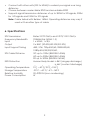
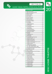
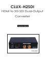
CLUX-H2SDI HDMI to 3G SDI Dual-Output Converter Operation Manual CLUX-H2SDI Disclaimers The information in this manual has been carefully checked and is believed to be accurate. Cypress Technology assumes no responsibility for any infringements of patents or other rights of third parties which may result from its use. Cypress Technology assumes no responsibility for any inaccuracies that may be contained in this document. Cypress also makes no commitment to update or to keep current the information contained in this document. Cypress Technology reserves the right to make improvements to this document and/or product at any time and without notice. Copyright Notice No part of this document may be reproduced, transmitted, transcribed, stored in a retrieval system, or any of its part translated into any language or computer file, in any form or by any means - electronic, mechanical, magnetic, optical, chemical, manual, or otherwise - without express written permission and consent from Cypress Technology. © Copyright 2009 by Cypress Technology. All Rights Reserved. Version 1.0 October 2009 Trademark Acknowledgments All products or service names mentioned in this document may be trademarks of the companies with which they are associated. Safety Precautions Please read all instructions before attempting to unpack or install or operate this equipment, and before connecting the power supply. Please keep the following in mind as you unpack and install this equipment: Always follow basic safety precautions to reduce the risk of fire, electrical shock and injury to persons. To prevent fire or shock hazard, do not expose the unit to rain, moisture or install this product near water. Never spill liquid of any kind on or into this product. Never push an object of any kind into this product through module openings or empty slots, as you may damage parts. Do not attach the power supply cabling to building surfaces. Do not allow anything to rest on the power cabling or allow it to be abused by persons walking on it. To protect the equipment from overheating, do not block the slots and openings in the module housing that provide ventilation. Revision History Version No Date V1 20101004 Summary of Change Preliminary Release Table of Contents 1. 2. 3. 4. 5. 6. 7. Introduction................................................................................... 1 Applications.................................................................................. 1 Package Contents....................................................................... 1 System Requirements................................................................... 1 Features......................................................................................... 1 Specifications............................................................................... 2 Operation Controls and Functions.............................................. 3 7.1 Front Panel..................................................................... 3 7.2 Rear Panel..................................................................... 5 8. LED Signal Chart............................................................................ 6 9. Connection and Installation . ..................................................... 8 10.Acronyms...................................................................................... 9 1. Introduction The HDMI™ to 3G SDI converter allows HDMI signals to be shown on SDI displays while ensuring high bit rates of 2.970 Gbit/s to give you high resolution signal without any loss. For professionals this means that it is now easier to convert your high def HDMI signal with audio to 3G SDI for long distance transmission and display your work on two 3G SDI display. Also, a 2CH L/R audio input allows DVI signal with 2CH audio to be converted to SDI in order to be shown on SDI displays. Furthermore, the device has a built-in default EDID and a recordable EDID that guaranty image display compatibility with source equipment. 2. Applications • • • • HDMI signal display on SDI display(s) Extending HDMI signal over 100M away to two SDI display DVI signal with audio display on SDI display(s) Cascade HDMI signal over SDI cable 3. Package Contents • HDMI™ to 3G SDI converter • 5V/2.6A Power Adaptor • Operation Manual 4. System Requirements • Input HDMI/DVI (with audio signal) source equipment with connection cable(s). • Output SDI display(s) or SDI to HDMI converter(s) with connection cable(s). 5. Features • • • • • • Supports HDMI timing: 480i, 576i, 720p50/60, 1080p 24/25/30, 1080i 50/60, 1080p 50/60 Operation at 2.970Gbit/s, 2.970/1.001Gbit/s, 1.485Gbit/s, 1.485/1.001Gbit/s and 270Mbits/s Simultaneous display HDMI source on two SDI displays When a DVI signal goes through HDMI, the R/L audio can be sent with it to the 3G SDI output Integrated audio embedded up to 8 channel PCM 48kHz for HDMI or 2CH for DVI audio Auto video mode detection (3G/SD/HD) 1 • • • Connect with other units (SDI to HDMI) to extend your signal over long distances Choose between a selectable EDID and recordable EDID Supports signal transmission distances of up to 300M for SD signals, 200M for HD signals and 100M for 3G signals Note: Cable tested with Belden 1694A. Operating distances may vary if used w ith another type of cable 6. Specifications SDI Transmission Rates 2.970 Gbit/s and 2.970/1.001 Gbit/s Frequency Bandwidth 225MHz/link (HDMI 1.3) Input 1 x HDMI, 1 x R/L Output 2 x BNC (SD-SDI/HD-SDI/3G-SDI) Input Support Timing 480i, 576i, 720p@50/60,1080i@50/60, 1080p@24/25/30/50/60, SDI Cable Distance 3G up to 100M (BELDEN 1694A) HD up to 200M (BELDEN 1694A) SD up to 300M (BELDEN 1694A) ESD Protection Human Body Model: ± 8kV (air-gap discharge) : ± 4kV (contact discharge) Operating Temperature 0°C ~ 40°C/ 32°F ~104°F Storage Temperature -20°C ~ 60°C/ -4°F ~140°F Relative Humidity 20~90% RH (non-condensing) Power Consumption W 2 7. Operation Controls and Functions 7.1 Front Panel 3 4 6 7 1 ① 2 5 8 9 EDID Update button: Use this function only when the image does not display after trying to switch the EDID/HD/3G EDID swtich. EDID procedures as below. DVD Player HDMI CLUX-H2SDI SDI SDI Monitor A.Please make sure the DVD is set on “auto mode” in output timing's setting. If the image display properly, stop using this function but if no image display after the connection. go to step B. Adjust to SDI accept Timing DVD Player (HDMI Cable) HDMI TV/Monitor B. Connect HDMI source directly (without connecting to CLUX-H2SDI ) to HDMI monitor or TV to see if the image display and make sure the source's output timing is supporting SDI or CLUXH2SDI's timing. If yes, go to step C. If no, please change a different monitor or TV and adjust the timing until the image display. 3 CLUX-H2SDI 1.Switch the dip switch to EDID update postion 2.Pressed on the EDID update button consistently (HDMI Cable) HDMI TV/Monitor C.Connect the HDMI monitor or TV to the input port of CLUX-H2SDI and then set the dip switch to EDID update position. Press the EDID update button consistently until the Video Lock LED illuminate. In this step the device will updating the monitor/TV’s EDID to replace the default setting. DVD Player HDMI CLUX-H2SDI SDI SDI Monitor D.Finally, connect the HDMI source to the input port of CLUX-H2SDI and output connect to SDI monitor which should allow image display. 2. EDID Switch: Switching this switch to use the built-in or to update the EDID. Default EDID as below: 3G EDIDNative Mode 1080p@60 HD EDIDNative Mode 1080i@60 EDID update / SD EDIDNative Mode720p@60 3. EDID Update LED: This red LED will illuminate when EDID is being updating. Detail in Section “EDID Update”. 4. Video Lock LED: This yellow LED will illuminate when the input HDMI has received the signal and locked it. 5. HDMI/DVI LED: This green LED will illuminate when the input source is HDMI signal and will not illuminate when the input is DVI signal. 6. 3G LED: This red LED illuminate when the input HDMI signal is 1080p@50/60. 7. HD LED: This yellow LED illuminate when the input HDMI signal is 1080p@24/25/30, 1080i@50/60 or 720p@50/60. 8. SD LED: This green LED illuminate when the input HDMI signal is 480i/576i. 9. 3G SDI Out 1 & 2: Connect output SDI display up to 2 for mirror displays or with SDI to HDMI converter to cascade the signal as long as desired. 4 7.2 Rear Panel 1 2 3 4 5 1. HDMI In: This slot is to connect with the input source equipment such as DVD or Blue-Ray player with connection cable for input video and audio signal transmitting. Or it can also be connect with DVI source equipment for video signal transmitting. 2. Audio Switch: Switch this switch to allowing the audio to be send from HDMI or R/L. 3. Audio Switch: Switching this switch allowing the audio to be send from HDMI or R/L. 4. Audio In R/L: These slots are to connect with audio source equipment such as DVD or Blue-Ray player with output R/L RCA jack. 5. Power LED: This LED will illuminate in RED when the power is connected the AC supply. 6. DC 5V: Plug the 5V DC power supply into this unit and connect the adaptor to AC wall outlet. 5 8. LED Signal Chart System Operation LED Signal Status No. EDID EDID Singal LED EDID Video HDMI Switch key 3G HD SD Update /Lock /DVI Description 1 3G Not Pressed ● ● ● Input timing is 3G, HDMI mode 2 3G Not Pressed ● ● ● Input timing is HD, HDMI mode 3 3G Not Pressed ● ● ● Input timing is SD, HDMI mode 4 3G Not Pressed ● ● ● ● Input timing no support , HDMI mode 5 3G Not Pressed ● ● ● ● Input timing is 3G, DVI mode 6 3G Not Pressed ● ● ● ● Input timing is HD, DVI mode 7 3G Not Pressed ● ● ● ● Input timing is SD, DVI mode 8 3G Not Pressed ● ● ● ● ● Input timing no support , DVI mode 9 HD Not Pressed ● ● ● Input timing is 3G, HDMI mode 10 HD Not Pressed ● ● ● Input timing is HD, HDMI mode 11 HD Not Pressed ● ● ● Input timing is SD, HDMI mode 12 HD Not Pressed ● ● ● ● Input timing no support , HDMI mode 13 HD Not Pressed ● ● ● ● Input timing is 3G, DVI mode 14 HD Not Pressed ● ● ● ● Input timing is HD, DVI mode 15 HD Not Pressed ● ● ● ● Input timing is SD, DVI mode 16 HD Not Pressed ● ● ● ● ● Input timing no support , DVI mode 17 Update Not Pressed ● ● ● Input timing is 3G, HDMI mode 18 Update Not Pressed ● ● ● Input timing is HD, HDMI mode 19 Update Not Pressed ● ● ● Input timing is SD, HDMI mode 20 Update Not Pressed ● ● ● ● Input timing no support , HDMI mode 21 Update Not Pressed ● ● ● ● Input timing is 3G, DVI mode 22 Update Not Pressed ● ● ● ● Input timing is HD, DVI mode 23 Update Not Pressed ● ● ● ● Input timing is SD, DVI mode 24 Update Not Pressed ● ● ● ● ● Input timing no support , DVI mode 25 Update Not Pressed ● ● ● ● ● ● No input signal or No connect Note: 1. "" signal represent LED illuminate whereas "●" signal represent not. 2.Only a part of HDMI timing may be convert into SDI signal and therefore, default EDID setting selection provides source player with reference and propriety output timing. 6 3.EDID switch mode / Default EDID setting: 3G 1080p@60 HD 1080i@60 Update / SD 720p@60 4.Due to HDMI’s default timing are mainly set on 480p but SDI does not support such timing therefore, it is possible that the image will not dis play. To avoid such event, it is suggested to set the source input equip ment’s output timing on the “AUTO mode” for the source equipment to send the EDID native timing of the display. 5.Only No. 4,5,12,16,20 & 24 needs to do EDID update. Detail informa tion please refers to “EDID Update button”. EDID Update LED Confirm Status No. EDID EDID Singal LED EDID Video HDMI Switch key 3G HD SD Update /Lock /DVI Description 1 Update Pressed On ● ● 3G Native, HDMI mode, Read OK 2 Update Pressed On ● ● HD Native, HDMI mode, Read OK 3 Update Pressed On ● ● SD Native, HDMI mode, Read OK 4 Update Pressed On ● ● ● No support timing, HDMI mode, Read OK 5 Update Pressed On ● ● ● 3G Native, DVI mode, Read OK (Note4) 6 Update Pressed On ● ● ● HD Native, DVI mode, Read OK (Note4) 7 Update Pressed On ● ● ● SD Native, DVI mode, Read OK (Note4) 8 Update Pressed On ● ● ● ● EDID format error (Note5) 9 Update Pressed On ● ● ● ● ● No connection or connection error Note: 1. "" signal represent LED illuminate whereas "●" signal represent not and "" is blinking light. 2. Only when the EDID button is being pressed on consistently the EDID update will progress and when the update is complete the Video Lock LED will illuminate. If the button is not pressed the LED will illuminate according to “System Operation LED Signal Status”. 3. HDMI source sending output resolution is base on receiver side’s display monitor/TV’s EDID but different sources may have different handling progress. The EDID update function is made to solve compatibility issue. 4. When EDID read DVI mode the system will check if the EDID’s native mode support SDI timing. If yes, the display will show according to No. 5,6 & 7. If not, the system will automatically copy default DVI’s EDID (Native 3G) mode and show as No.5 Format 5. EDID format error includes: Header error, Checksum error and EDID error under this condition the default EDID or the updated will not be change. 7 9. Connection and Installation DVD 100M~300M Blu Ray 100M/300M CLUX-SDI2HC Sony SDI Monitor HDMI Monitor / TV 8 A Acronyms Acronym Complete Term 3G Bandwidth 2.97Gbit/s ≈ 3G SDI Serial Digital Interface 9 10 11 CYPRESSTECHNOLOGYCO.,LTD. Home page: http://www.cypress.com.tw MPM-CLUXH2SDI