1
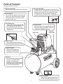
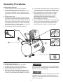
Owner’s Manual
®
AIR COMPRESSOR
20-gallon
1.5 HP
Oil-Free, Direct Drive
Model No. 921.166430
CAUTION:
Before using this product,
read this manual and follow
all its Safety Rules and
Operating Instructions.
•
•
•
•
•
•
Safety Instructions
Installation & Operation
Maintenance & Storage
Troubleshooting Guide
Parts List
Español, p. 10
Sears, Roebuck and Co., Hoffman Estates, IL 60179 U.S.A.
www.sears.com
02/26/2009
Part No. E103737
Table of Contents
Page
Warranty . . . . . . . . . . . . . . . . . . . . . . . . . . . . . . . . . . . . . . . . . . . . . . . . . . . . . . . . . . . . . . See Below
Safety Symbols . . . . . . . . . . . . . . . . . . . . . . . . . . . . . . . . . . . . . . . . . . . . . . . . . . . . . . . . . . 1
Important Safety Instructions & Guidelines . . . . . . . . . . . . . . . . . . . . . . . . . . . . . . . . . . . . . 1
Specifications . . . . . . . . . . . . . . . . . . . . . . . . . . . . . . . . . . . . . . . . . . . . . . . . . . . . . . . . . . . 2
Glossary . . . . . . . . . . . . . . . . . . . . . . . . . . . . . . . . . . . . . . . . . . . . . . . . . . . . . . . . . . . . . . . 2
Duty Cycle . . . . . . . . . . . . . . . . . . . . . . . . . . . . . . . . . . . . . . . . . . . . . . . . . . . . . . . . . . . . . . 2
Parts & Features . . . . . . . . . . . . . . . . . . . . . . . . . . . . . . . . . . . . . . . . . . . . . . . . . . . . . . . . . 3
Installation & Assembly . . . . . . . . . . . . . . . . . . . . . . . . . . . . . . . . . . . . . . . . . . . . . . . . . . . . 4
Operating Procedures . . . . . . . . . . . . . . . . . . . . . . . . . . . . . . . . . . . . . . . . . . . . . . . . . . . . . 5
Maintenance . . . . . . . . . . . . . . . . . . . . . . . . . . . . . . . . . . . . . . . . . . . . . . . . . . . . . . . . . . . . 6
Storage . . . . . . . . . . . . . . . . . . . . . . . . . . . . . . . . . . . . . . . . . . . . . . . . . . . . . . . . . . . . . . . .
6
Troubleshooting Guide . . . . . . . . . . . . . . . . . . . . . . . . . . . . . . . . . . . . . . . . . . . . . . . . . . . . 7
Exploded View . . . . . . . . . . . . . . . . . . . . . . . . . . . . . . . . . . . . . . . . . . . . . . . . . . . . . . . . . . . 8
Parts List . . . . . . . . . . . . . . . . . . . . . . . . . . . . . . . . . . . . . . . . . . . . . . . . . . . . . . . . . . . . . . . 9
Español . . . . . . . . . . . . . . . . . . . . . . . . . . . . . . . . . . . . . . . . . . . . . . . . . . . . . . . . . . . . . . . . 11
ONE YEAR FULL WARRANTY ON CRAFTSMAN AIR COMPRESSOR
If this Craftsman Air Compressor fails due to manufacturer’s defects in material or workmanship
within one year of the date of purchase, RETURN IT TO THE NEAREST SEARS STORE OR
SERVICE CENTER IN THE UNITED STATES and it will be replaced or repaired (at our option),
free of charge.
If this Air Compressor is used for commercial or rental purposes, this warranty applies for only 90
days from the date of purchase. This warranty gives you specific legal rights and you may also
have other rights which vary from state to state.
Sears, Roebuck and Co., Hoffman Estates, IL 60179
Safety Symbols
The information listed below should be read and understood by the operator. This information is given to protect the
user while operating and storing the air compressor. We utilize the symbols below to allow the reader to recognize important
information about their safety.
CAUTION
DANGER
Indicates an imminently hazardous situation which, if not
avoided, will result in death or serious injury.
Indicates a potentially hazardous situation which, if not
avoided, may result in minor or moderate injury.
CAUTION
WARNING
When used without the safety alert symbol indicates a
potentially hazardous situation which, if not avoided, may
result in property damage.
Indicates a potentially hazardous situation which, if not
avoided, could result in death or serious injury
Important Safety Instructions and Guidelines
• Save all instructions
WARNING
Improper operation or maintenance of this product could result in serious injury and/or property damage. Read and
understand all of the warnings and safety instructions provided before using this equipment.
CAUTION
The air compressor should be operated on a dedicated 15 amp circuit. If the circuit does
not have 15 free amps available, a larger circuit must be used. Always use more air
hose before utilizing extension cords. All extension cords used must be 12 gauge with a
maximum length of 25 ft. The circuit fuse type must be a time delay. Low voltage could
cause damage to the motor.
Risk of Moving Parts
If the air compressor is in operation, all guards and covers should be attached or
installed correctly. If any guard or cover has been damaged, do not operate the
equipment until the proper personnel has correctly repaired the equipment. The power
cord should be free of any moving parts, twisting and/or crimping while in use and while
in storage.
Risk of Burns
There are surfaces on your air compressor that while in operation and thereafter can
cause serious burns if touched. The equipment should be allowed time to cool before
any maintenance is attempted. Items such as the compressor pump and the outlet tube
are normally hot during and after operation.
Risk of Falling
Operation of the air compressor should always be in a position that is stable. Never use
the air compressor on a rooftop or elevated position that could allow the unit to fall or
be tipped over. Use additional air hose for elevated jobs.
Risk from Flying Objects
Always wear ANSI Z87.1 approved safety glasses with side shields when the air
compressor is in use. Turn off the air compressor and drain the air tank before
performing any type of maintenance or disassembly of the hoses or fittings. Never point
any nozzle or sprayer toward any part of the body or at other people or animals.
1
Important Safety Instructions & Guidelines
Risk of Breathing
Avoid using the air compressor in confined areas. Always have adequate space
(12 inches) on all sides of the air compressor. Also keep children, pets, and others out of
the area of operation. This air compressor does not provide breathable air for anyone or
any auxiliary breathing device. Spraying material will always need to be in another area
away from the air compressor to not allow intake air to damage the air compressor filter.
Risk of
Electrical Shock
Never utilize the air compressor in the rain or wet conditions. Any electrical issues or
repairs should be performed by authorized personnel such as an electrician and should
comply with all national and local electrical codes. The air compressor should also have
the proper three prong grounding plug, correct voltage, and adequate fuse protection.
Risk of
Explosion or Fire
Never operate the compressor near combustible materials, gasoline or solvent vapors.
If spraying flammable materials, locate the air compressor at least 20 feet away from the
spray area. Never operate the air compressor indoors or in a confined area.
Risk of Bursting
Always drain the air compressor tank daily or after each use. If the tank develops a leak,
then replace the air compressor. Never use the air compressor after a leak has been
found or try to make any modifications to the tank. Never modify the air compressor’s
factory settings which control the tank pressure or any other function.
Specifications
Pump . . . . . . . . . . . . . . . . . . . . . . . . . Oil-Free Direct Drive
Motor . . . . . . . . . . . . . . . . . . . . . . . . . . . . . . . . . . . . 1.5 HP
Bore . . . . . . . . . . . . . . . . . . . . . . . . . . . . . . . . . . . . . . . 2.28˝
Stroke . . . . . . . . . . . . . . . . . . . . . . . . . . . . . . . . . . . . . 0.87˝
Voltage Single Phase . . . . . . . . . . . . . . . . . . . . . . 120 VAC
Minimum Circuit Requirement . . . . . . . . . . . . . . 15.0 Amps
Air Tank Capacity . . . . . . . . . . . . . . . . . . . . . . . 20 Gallons
Cut-in Pressure . . . . . . . . . . . . . . . . . . . . . . . . . . . . 120 PSI
Cut-out Pressure . . . . . . . . . . . . . . . . . . . . . . . . . . . 150 PSI
SCFM @ 90 PSI . . . . . . . . . . . . . . . . . . . . . . . . . . . . . . 3.8
SCFM @ 40 PSI . . . . . . . . . . . . . . . . . . . . . . . . . . . . . . 5.1
Glossary
CFM: Cubic feet per minute.
SCFM: Standard cubic feet per minute; a unit of measure
for air delivery.
PSIG: Pounds per square inch gauge; a unit of measure
for pressure.
ASME: American Society of Mechanical Engineers.
California Code: Unit may comply with California Code
462 (l) (2)/ (M) (2).
Cut-In Pressure: The air compressor will automatically
start to refill the tank when the pressure drops
below the prescribed minimum.
Cut-Out Pressure: The point at which the motor stops
when the tank has reached maximum air
pressure.
Code Certification: Products that bear one or more of
the following marks: UL, ULc, ETL, CSA, have
been evaluated by OSHA-certified independent
safety laboratories and meet the applicable
Underwriters Laboratories Standards for Safety.
Duty Cycle
This is a 50% duty cycle air compressor. Do not run the air compressor more than 30 minutes of one hour. Doing so
could damage the air compressor.
2
Parts & Features
See figures below for reference
Tank Pressure Gauge
Indicates the reserve air pressure in the tank.
Pressure Relief Valve
The pressure relief valve located on the side of the
pressure switch, is designed to automatically release
compressed air when the air compressor reaches cut-out pressure. The released air should only
escape momentarily and the valve should then close.
Pressure Switch
This controls the power to the motor and also the cut-in/cut-out pressure settings.
This switch serves as the Auto-On/Off
positions for the unit.
Tank Safety Valve
Used to allow excess tank pressure
to escape into the atmosphere. This
valve should only open when the
tank pressure is above the maximum
rated pressure.
Air Intake Filter
Provides clean air to the pump and must always be kept free of debris. Check on a daily basis or before each use.
Outlet Tube
Pressure
Relief Tube
Quick Connect
Offers a quick release feature for attaching and removing the air hose.
Regulator Gauge
Indicates the outgoing air
pressure to the tool and is
controlled by the regulator.
Regulator
The air pressure coming from the
air tank is controlled by the
regulator. To increase the
pressure turn the knob clockwise
and to decrease the pressure turn
the knob counterclockwise.
Tank Drain Valve
Used to drain condensation from the air tank. Located at bottom of tank.
3
Installation & Assembly
WARNING
The air compressor should be turned off, unplugged from
the power source, the air bled from the tank and the unit
allowed time to cool before any maintenance is performed.
Personal injuries could occur from moving parts, electrical
sources, compressed air or hot surfaces. The quick connect
assembly must be attached before use. Failure to assemble
correctly could result in leaks and possible injury. If unsure
of assembly instructions or you experience difficulty in the
assembly please call your local service department for
further information.
Improper installation of the grounding plug will result in a
risk of electric shock. If repair or replacement of the cord
or plug is necessary, do not connect the grounding wire to
either flat blade terminal. The wire with insulation having an
outer surface that is green with or without yellow stripes is
the grounding wire. Check with a qualified electrician or
serviceman if the grounding instructions are not completely
understood, or if in doubt as to whether the product is
properly grounded. Do not modify the plug provided.
If it will not fit the outlet, have the proper outlet installed
by a qualified electrician.
Getting Started - Location of the Air Compressor
The air compressor should always be located in a clean,
dry and well ventilated environment. The unit should have
at minimum, 12 inches of space on each side. The air filter
intake should be free of any debris or obstructions.
Check the air filter on a daily basis to make sure it is clean
and in working order.
This product is for use on a circuit having a nominal rating
of 120 volts and is factory-equipped with a specific electric
cord and plug to permit connection to a proper electric
circuit. Make sure the product is connected to an outlet
having the same configuration as the plug. An adapter
should not be used with this product. If the product must
be reconnected for use on a different type of electric circuit,
qualified service personnel should make the reconnection.
WARNING
Extension Cords
Use only a 3-wire extension cord that has a 3-blade
grounding plug and a 3-slot receptacle that will accept the
plug on the product. Make sure your extension cord is in
good condition. When using an extension cord, be sure to
use one heavy enough to carry the current your product will
draw. Cords must not exceed 25 feet and No. 12 AWG size
must be used. An undersized cord will cause a drop in line
voltage resulting in loss of power and overheating.
Risk Of Fire Or Explosion
This product incorporates snap action switch contacts and
a universal electric motor which tend to produce arcs and
sparking and therefore should not be exposed to flammable
liquids or vapors. This product is not intended for installation
or use in a commercial garage or shop environment.
WARNING
Grounding Instructions
This product should be grounded. In the event of an electrical
short circuit, grounding reduces the risk of electric shock by
providing an escape wire for the electric current.
This product is equipped with a cord having a grounding
wire with an appropriate grounding plug. (See the figure
below.) The plug must be plugged into an outlet that is
properly installed and grounded in accordance with all local
codes and ordinances. Check with a qualified electrician or
service personnel if these instructions are not completely
understood or if in doubt as to whether the tool is properly
grounded.
Break In Procedures
No break in procedure is required by the user.
This product is factory tested to ensure proper operation and
performance.
Plug
Grounded
Outlet
Grounding Pin
4
Operating Procedures
Daily Start-Up Procedures
1. Set the Auto-On/Off switch to the Off position.
2. Inspect the air compressor, air hose, and any accessories/tools being used for damage or obstruction.
If any of these mentioned items are in need of repair/
replacement, contact your local authorized dealer before use.
3. Close the drain valve.
4. Connect the air hose to the quick connect socket on
the regulator assembly by inserting the quick connect
plug on the air hose into the quick connect socket. The
quick connect socket collar will snap forward and lock
the plug into place providing an air tight seal between
the socket and plug. To release the air hose push the
collar back on the quick connect socket.
5. Plug the power cord into the proper receptacle.
6. Turn the Auto-On/Off switch to the On-Auto position and
the compressor will start and build air pressure in the
tank to cut-out pressure and then shut off automatically.
7. Adjust the regulator to a PSI setting that is needed for
your application and be sure it is within the safety
standards required to perform the task. If using a
pneumatic tool, the manufacturer should have
recommendations in the manual for that particular
tool on operating PSI settings.
8. The air compressor is now ready for use. The following
inflation and cleaning accessories packaged with this
unit should only be operated at maximum pressure
of 90PSI: Blow gun, adapter and inflation needle.
6
4
AU
TO
OFF
!
1
OFF
5
7
3
Daily Shut-Down Procedures
1. Set the Auto-On/Off switch to the Off position.
2. Unplug the power cord from the receptacle.
3. Set the outlet pressure to zero on the regulator.
4. Remove any air tools or accessories.
5. Open the drain valve allowing air to bleed from the
tank. After all of the air has bled from the tank, close
the drain valve to prevent debris buildup in the valve.
CAUTION
When draining the tank, always use ear and eye protection.
Drain the tank in a suitable location; condensation will be
present in most cases of draining.
WARNING
Water that remains in the tank during storage will corrode
and weaken the air tank which could cause the tank to
rupture. To avoid serious injury, be sure to drain the tank
after each use or daily.
5
Maintenance
NOTE: Any service procedure not covered in the
maintenance schedule should be performed by qualified
service personnel.
Maintenance Schedule
Items to Check/Change
WARNING
The air compressor should be turned off, unplugged from
the power source, air bled from the tank and allowed
time to cool before any maintenance is performed.
Before each use
or daily
Check Tank Safety Valve
X
Overall Unit Visual Check
X
Drain Tank
X
Check Power Cord for Damage
X
WARNING
Do not attempt to remove or adjust the safety valve.
CAUTION
To ensure efficient operation and longer life of the air
compressor unit, a routine maintenance schedule should
be followed. The following schedule is geared toward a
consumer whose compressor is used in a normal working
environment on a daily basis.
Check the safety valve by performing these three steps:
1. Plug the compressor in and run until shut-off pressure
is reached.
2. Wearing safety glasses, pull out on the safety valve ring
to release pressure from the tank.
3. The safety valve should close automatically at
approximately at 40-50 PSI. If the safety valve does not
allow air to be released when you pull out on the ring, or
does not close automatically, it must be replaced.
CAUTION
This compressor is equipped with an automatic reset
thermal overload protector which will shut off motor if it
becomes overheated. If the thermal overload protector is
actuated, the motor must be allowed to cool down before
start-up is possible.
NOTE: The motor will automatically restart without warning if the unit is left plugged in to an outlet with the AutoOn/Off switch in the on position
Storage
For storing the air compressor, be sure to do the following:
1. Turn the unit off and unplug the power cord from the
receptacle.
2. Remove all air hoses, accessories, and air tools from
the air compressor.
3. Perform the daily maintenance schedule.
4. Open the drain valve to bleed all air from the tank.
5. Close the drain valve.
6. Store the air compressor in a clean and dry location.
6
Troubleshooting Guide
The air compressor should be turned off and unplugged from the power source before any maintenance
WARNING is performed as well as the air bled from the tank and the unit allowed time to cool. Personal injuries
could occur from moving parts, electrical sources, compressed air, or hot surfaces.
PROBLEM
POSSIBLE CORRECTION
Air leaks at the check valve or at the pressure relief valve.
A defective check valve results in a constant air leak at the pressure relief
valve when there is pressure in the tank and the compressor is shut off.
Drain the tank, then remove and clean or replace the check valve.
Air leaks between head and cylinder.
Be sure of proper torque on head bolts. If leak remains, contact a service
technician.
Air leak from safety valve.
Operate the safety valve manually by pulling on the ring. If the valve continues to leak when in the closed position, it should be replaced.
Pressure reading on the regulated
pressure gauge drops when an accessory
is used.
If there is an excessive amount of pressure drop when the accessory is
used, replace the regulator.
NOTE
Adjust the regulated pressure under flow conditions (while accessory is
being used). It is normal for the gauge to show minimal pressure loss during initial use of the tool.
Excessive tank pressure.
Move the Auto-On/Off switch to the Off position. If the unit doesn’t shut
off, unplug it from the power source and contact a service technician.
Motor will not start.
Make sure the Thermal Overload Switch on the back of the motor is
pushed in.
Make sure power cord is plugged in and the switch is on. Inspect for the
proper size fuse in your circuit box. If the fuse was tripped, reset it and
restart the unit. If repeated tripping occurs, replace the check valve or
contact a service technician.
Thermal overload protector cuts
out repeatedly.
1. Lack of ventilation, room temperature too high. Move to cooler
environment.
2. Excessive air usage, compressor too small for this application. Lower
rate of consumption.
Excessive moisture in the discharge air.
Remove the water in the tank by draining after each use. High humidity
environments will cause excessive condensation. Utilize water filters on
your air line.
NOTE
Water condensation is not caused by compressor malfunction. Be sure
the compressor’s air output is greater than your tool’s air consumption
rate.
Air leaks from the tank body or tank welds.
Never drill into, weld or otherwise modify the air tank or it will weaken.
The tank can rupture or explode. Compressor cannot be repaired.
Discontinue use of the air compressor.
7
Air Compressor Model 921.166430
Exploded View
5
32
6
7
33
34
9
10
11
13
4
2
12
15
22
27
28
29
31
24
3
8
14
1
16
23
17
21
25
26
30
35
47
65
39
62
40
43
42
46
18
38
37
36
20
19
61
64
63
41
60
59
45
44
58
57
56
48
52
49
8
51
50
53
54
55
Air Compressor Model 921.166430
Parts List
Ref.
No.
1
2
3
4
5
6
7
8
9
10
11
12
13
14
15
16
17
18
19
20
21
22
23
24
25
26
27
28
29
30
31
32
33
34
35
36
37
38
Kit
No.
3
3
3
2
2
2
2
2
2
2
2
2
1
1
1
1
1
1
1
1
1
1
Part
Number
Description
E100300 Shroud, F2, Full, Rear
Air Filter, Cap
Air Filter, Element
Air Filter, Base
Screw, M6 x 1 x 35, SHCS
Head, F2
O-Ring, Head
Screw, M3 x 0.4 x 5mm, HFHS
Retainer, Outlet Valve
Valve, Outlet
Plate, Valve
Valve, Inlet
Retainer, Inlet Valve
Screw, M3 x 0.4 x 5mm, HFHS
O-Ring, Cylinder
Cylinder, Steel, Coated
Motor, Oil Free, 1.5 hp
Screw, M6 x 1 x 35, SHCS
Eccentric
Screw, M5, 0.8 x 25mm, SHCS
Bearing, C & U
Screw, M5 x 0.8 x 16mm, SHCS
Cap, Piston
Ring, Piston
Piston
Nut, M5 x 0.8
E100297 Fan, F2
Washer, Flat, M5
Washer, Lock, M5
Screw, M5 x 0.8 x 15mm,
Left Hand Threads
E100296 Shroud, F2, Full, Front
Elbow, 13mm Flare
Nut, 13mm Flare
E103636 Tube, Outlet, Copper with Fins
(Includes #33)
E103641 Shroud, Manifold, Sears F220H
E103637 Tube, Relief, Aluminum
E102612 Valve, Safety, 165 psi
E103744 Gauge, 2”, 150psi Red Line,
250psi max, Back Inlet
Quantity
Ref.
No.
Kit
No.
39
40
41
42
43
1
1
1
1
4
1
1
1
1
1
1
1
1
1
1
1
1
1
1
1
1
1
1
1
1
1
1
1
1
44
45
46
47
48
49
50
51
52
53
54
55
56
57
58
59
60
61
62
63
64
65
1
1
1
1
1
4
4
Part
Number
Description
Quantity
E102750 Switch, Pressure, 150psi Cut Out
Nipple, 1/4” mnpt x 40 mm
E100898 Valve, Check, 90 degree, Right
E103638 Hose, Manifold
E103744 Gauge, 2”, 150psi Red Line,
250psi max, Back Inlet
Elbow, 1/4 mnpt x 1/4 fnpt, 45 degree
E101951 Manifold
E100307 Coupler, Quick Connect
E103639 Handle, Sears F220H
Tank, Asm
Screw, M6 x 1 x 20mm, SHC
E100305 Isolator
E101717 Drain, 1/4 Turn
Nut, Lock, M10 x 1.25
Wheel, Sears, 8 in
Bolt, M10 x 1.25 x 35mm, HH
Hubcap, Sears, Black
Screw, M6 x 1 x 16, SHCS
Washer, Lock, M6
Washer, Flat, M6
Bolt, M8 x 1.25 x 25
Washer, Lock, M8
Washer, Flat, M8
Screw, M6 x 1 x 12, HFHS
Nut, M8 x 1.25
Screw, M8 x 1.25 x 15, HFH
Power Cord
1
1
1
1
1
1
1
2
1
1
2
2
1
2
2
2
2
2
2
2
4
4
4
6
4
4
1
Note: Any part/kit number field without a number is not available. Descriptions
are provided for reference only. The Kit # column represents that the part being
offered is available in a kit. One of each part per kit will be offered.
Kit number and parts that are included are as follows:
Kit No. Part No.
Description
Reference No.
1
1
1
1
2
3
4
1
9
E103495
E103497
E100794
E102369
Piston Kit
Valve Plat Kit
Air Filter Kit
Wheel Kit (one wheel only)
16, 18-26
7-15
2-4
53, 55
Manual de
®
AIR COMPRESSOR
75.7 litros
1.5 HP
De impulsión directa,
Sin aceite
Model No. 921.166430
PRECAUCIÓN: Antes de usar
el producto, lea este manual y siga
sus reglas e instrucciones
de seguridad.
• Instrucciones y pautas de seguridad importantes
• Instalación y operación
• Mantenimiento y Almacenamiento
• Diagnóstico y corrección de fallas
• Lista de las piezas
Sears, Roebuck and Co., Hoffman Estates, IL 60179 U.S.A.
www.sears.com
02/26/2009
Part No. E103737
Contenido
Página
Garantía
esta página
Símbolos de seguridad . . . . . . . . . . . . . . . . . . . . . . . . . . . . . . . . . . . . . . . . . . . . . . . . . . . . . . . 13
Important Safety Instructions & Guidelines . . . . . . . . . . . . . . . . . . . . . . . . . . . . . . . . . . . . . 13
Especificaciones . . . . . . . . . . . . . . . . . . . . . . . . . . . . . . . . . . . . . . . . . . . . . . . . . . . . . . . . . . . . 14
Glosario
. . . . . . . . . . . . . . . . . . . . . . . . . . . . . . . . . . . . . . . . . . . . . . . . . . . . . . . . . . . . . . . . 14
Ciclo de trabajo . . . . . . . . . . . . . . . . . . . . . . . . . . . . . . . . . . . . . . . . . . . . . . . . . . . . . . . . . . . . 14
Partes y características . . . . . . . . . . . . . . . . . . . . . . . . . . . . . . . . . . . . . . . . . . . . . . . . . . . . . . . 15
Instalación y ensamblaje . . . . . . . . . . . . . . . . . . . . . . . . . . . . . . . . . . . . . . . . . . . . . . . . . . . . . . 16
Procedimientos de operación . . . . . . . . . . . . . . . . . . . . . . . . . . . . . . . . . . . . . . . . . . . . . . . . . . . 17
Mantenimiento . . . . . . . . . . . . . . . . . . . . . . . . . . . . . . . . . . . . . . . . . . . . . . . . . . . . . . . . . . . . . 18
Almacenamiento . . . . . . . . . . . . . . . . . . . . . . . . . . . . . . . . . . . . . . . . . . . . . . . . . . . . . . . . . . . . 18
Diagnóstico y corrección de fallas . . . . . . . . . . . . . . . . . . . . . . . . . . . . . . . . . . . . . . . . . . . . . . . . 19
Vista esquemática . . . . . . . . . . . . . . . . . . . . . . . . . . . . . . . . . . . . . . . . . . . . . . . . . . . . . . . . . . 20
Lista de las piezas . . . . . . . . . . . . . . . . . . . . . . . . . . . . . . . . . . . . . . . . . . . . . . . . . . . . . . . . . . 21
GARANTÍA COMPLETA DURANTE UN AÑO DEL COMPRESOR DE AIRE CRAFTSMAN
Si este compresor de aire Craftsman fallase debido a defectos en materiales y mano de obra
dentro de un año a partir de la fecha de compra, DEVOLVERLO AL ESTABLECIMIENTO O
CENTRO DE SERVICIO SEARS MÁS CERCANO EN LOS ESTADOS UNIDOS y éste será
reemplazado o reparado (a nuestra opción), gratuitamente.
Si este compresor de aire se utiliza para fines comerciales o de alquiler, esta garantía es válida
solo durante 90 días a partir de la fecha de compra. Esta garantía brinda al comprador original
del producto derechos legales específicos; el comprador original también podría tener otros
derechos, los cuales varían de un estado a otro.
Sears, Roebuck and Co., Hoffman Estates, IL 60179
Símbolos comunes de seguridad
El operador debe leer y entender la información descrita a continuación. Esta información se ofrece para proteger al
usuario al operar y almacenar el compresor de aire. Los símbolos siguientes son los que se utilizan para indicar al lector
información que es importante para su seguridad.
PRECAUCIÓN
PELIGRO
Indica una situación de riesgo inminente que, al no
protegerse, provocará lesiones graves o la muerte.
Indica una situación potencialmente peligrosa que, de no
evitarse, podría provocar lesiones menores o moderadas.
PRECAUCIÓN
ADVERTENCIA
Cuando no aparezca sin el símbolo de alerta de seguridad, ésto
quiere decir que hay una situación potencialmente peligrosa
que, al no protegerse, podría causar daños materiales.
Indica una situación potencialmente peligrosa que, al no
protegerse, podría provocar lesiones graves o la muerte.
Instrucciones y pautas de seguridad importantes
• Guarde todas las instrucciones
ADVERTENCIA
La operación y el mantenimiento inadecuados de este producto pueden provocar lesiones graves y daños materiales. Antes de utilizar este equipo,
lea y entienda las advertencias e instrucciones de seguridad aquí contenidas.
PRECAUCIÓN
Riesgo por partes en
movimiento
Riesgo de quemaduras
Riesgo de caída
Riesgo de lanzamiento
de objetos
El compresor de aire se debe operar desde un circuito especial de 15 amperios.
Si el circuito no dispone de una capacidad de 15 amperios, se debe usar un circuito
de mayor capacidad. Si es necesario, antes de emplear una extensión eléctrica, añada
una manguera de aire más larga. Las extensiones eléctricas deben ser de calibre 12
y tener una longitud máxima de 7,6 metros. El fusible del circuito debe ser de acción
retardada. Un voltaje demasiado bajo puede dañar el motor.
Al operar el compresor, todos los protectores y cubiertas deben estar fijados e
instalados correctamente. Si alguno de los protectores o cubiertas está dañado, no
opere el equipo hasta que personal calificado repare el problema. El cable de corriente
debe mantenerse alejado de las partes móviles del equipo y no debe torcerse ni
prensarse durante su empleo, ni al almacenarse.
En su compresor hay superficies que, al ser tocadas durante y después de su
operación, pueden causar quemaduras graves. Antes de darle mantenimiento al
equipo, se debe dejar enfriar. Por lo normal, durante y después de su operación,
ciertas partes como la bomba del compresor y el tubo de salida estarán calientes.
El compresor siempre debe ser operado en una posición estable. Nunca utilice el
compresor sobre un techo o en una posición elevada ya que podría caer o
volcarse. Al trabajar en posiciones elevadas, utilice una manguera de aire más larga.
Al emplear el compresor, siempre utilice anteojos de seguridad con protectores
laterales que cumplan con la norma ANSI Z87.1. Antes de llevar a cabo cualquier clase
de mantenimiento y antes de desconectar las mangueras y los acopladores, apague
el compresor y drene el tanque de aire. Nunca apunte la boquilla o el rociador hacia
ninguna parte de su cuerpo, ni él de otros seres.
13
Instrucciones y pautas de seguridad importantes
Riesgo para la
respiración
Evite utilizar el compresor de aire en áreas encerradas. Siempre tenga un espacio
libre adecuado (30 cm.) en todos los lados del compresor. También mantenga fuera
del área de operación a las mascotas, niños y otras personas. Este compresor de aire
no provee aire que pueda ser respirado ni empleado con un dispositivo respiratorio
auxiliar. El material de rociado siempre deberá estar en otra zona, alejado del compresor
de aire, para evitar que el aire aspirado dañe al filtro del compresor.
Riesgo de
descargas eléctricas
Nunca utilice el compresor de aire bajo lluvia o en lugares mojados. Los problemas
eléctricos deben ser reparados por personal autorizado, tal como sería un electricista,
y deben cumplir con las normas eléctricas nacionales y locales. El compresor también
debe tener la clavija apropiada de tres terminales para hacer tierra y contar con
un suministro eléctrico que sea del voltaje correcto y con un fusible de protección
adecuado.
Riesgo de
explosión y fuego
Nunca opere el compresor cerca de materiales combustibles, gasolina ni vapores
de solventes. Si está rociando materiales inflamables, coloque el compresor a una
distancia de cuando menos 6 metros del área de rociado. Nunca opere el compresor
de aire en interiores o en lugares cerrados.
Riesgo de estallido
Drene el compresor diariamente o después de cada utilización. Si el tanque tiene una
fuga, reemplace el compresor. Nunca utilice el compresor si se ha detectado una fuga,
ni trate de modificar el tanque. Nunca modifique los ajustes de fábrica del compresor
que controlan la presión del tanque y demás funciones.
Especificaciones
Bomba . . . . . . . . . . . . . . . . . . . . . Sin aceite, De impulsión
directa
Motor . . . . . . . . . . . . . . . . . . . . . . . . . . . 1.5 HP (Universal)
Diámetro . . . . . . . . . . . . . . . . . . . . . . . . . . . . . . . . . 58 mm
Carrera . . . . . . . . . . . . . . . . . . . . . . . . . . . . . . . . . . 22 mm
Voltaje monofásico . . . . . . . . . . . . . . . . . . . . . . . . 120 VAC
Capacidad mínima del circuito . . . . . . . . . . . . . . . . . 15.0 A
Capacidad del tanque de aire . . . . . . . . . . . . . . . 75.7 litros
Presión de arranque . . . . . . . . . . . . . 827.4 KPa / 120 PSI
Presión de parada . . . . . . . . . . . . . . 1034.2 KPa / 150 PSI
Pies cúbicos por minuto (SCFM) a 90 LPPC . . . . . . . . . . . . . . . . . . . . 3.8
Pies cúbicos por minuto (SCFM) a 40 LPPC . . . . . . . . . . . . . . . . . . . . 5.1
Glosario
CFM: Pies cúbicos por minuto.
Presión de arranque: El compresor arranca automáticamente cuando la presión baja a menos del mínimo
prescrito.
Presión de parada: El motor se para cuando el tanque
alcance la presión máxima de aire.
Certificación de código: Los productos que tienen
alguna o varias de las siguientes marcas han sido
evaluados por laboratorios de seguridad
independientes certificados por OSHA, y cumplen
con las normas de seguridad de Underwriters
Laboratories: UL, , ETL, CSA.
SCFM: Pies cúbicos estándar por minuto; unidad de medición de suministro del aire.
PSIG: Libras por pulgada cuadrada sobre la presión
atmosférica; unidad de medición de presión.
ASME: Sociedad estadounidense de ingenieros mecánicos.
Código de California: La unidad puede cumplir con el
código de California 462 (l) (2)/ (M) (2).
Ciclo de trabajo
Este compresor tiene un ciclo de trabajo de 50%. Nunca opere el compresor por más de 30 minutos cada hora.
Ya que al hacerlo, podría dañarlo.
14
Partes y características
Como referencia, vea las figuras abajo.
Manómetro de presión del tanque
Válvula de alivio de presión
Indica la presión de la reserva de aire del tanque.
Esta válvula, que se encuentra en el costado del interruptor de presión, está diseñada para liberar aire comprimido de manera automática cuando el
compresor llegue a la presión de parada. El aire sólo deberá escapar durante un instante, cerrándose la válvula se cerrará en seguida.
Interruptor de presión
Controla el suministro eléctrico en el motor y
también los ajustes de presión de arranque y
presión de parada. Este interruptor sirve como
posición de autoencendido y apagado (Auto-On/
Off) de la unidad.
Válvula de seguridad del tanque
Permite que el exceso de presión en el tanque escape hacia el medio ambiente. Esta válvula sólo se abrirá cuando la resión en el tanque esté por encima de la presión máxima nominal del modelo.
Filtro del aire
Suministra aire limpio a la bomba. Siempre
debe conservarlo limpio. Revíselo iariamente o antes de cada uso.
Tubo de
alivio de
presión
Tubo de salida
Conector de acoplamiento rápido
Permite conectar y desconectar pidamente
la manguera del aire.
Manómetro de presión de salida
Indica la presión de salida del aire que entra en la herramienta, la cual que es controlada por el regulador.
Regulador
La presión del aire que sale del tanque es controlada por el
regulador. Para aumentar la presión, gire la perilla en dirección de las manecillas; para disminuirla, gire la perilla en dirección contraria a las manecillas.
Válvula de drenaje
Sirve para drenar la condensación
acumulada en el fondo del tanque. Se encuentra en la parte inferior del tanque.
15
Instalación y ensamblaje
ADVERTENCIA
Antes de darle cualquier tipo de mantenimiento al compresor
de aire, se debe apagar y desconectar de la fuente de
alimentación eléctrica, además de purgar el aire del tanque
y darle suficiente tiempo para enfriarse. Existe el riesgo
de que las partes móviles, las fuentes eléctricas, el aire
comprimido y las superficies calientes provoquen lesiones.
El ensamblaje de conexión rápida debe estar instalado
antes de usar el compresor. Un ensamblaje inadecuado
puede ser causa de fugas y posiblemente de lesiones.
En caso de dudas sobre las instrucciones de montaje o
dificultad en el montaje, por favor llamar al departamento
de servicio local para mayor información.
Una conexión a tierra inadecuada puede provocar una
descarga eléctrica. Si necesita reparar o cambiar el cable o
la clavija, no conecte el alambre de tierra con ninguna de las
terminales planas. El alambre de tierra es de color verde,
con o sin franjas amarillas. Si no entiende completamente
las instrucciones de conexión a tierra, o si tiene dudas sobre
la correcta puesta a tierra de la herramienta, hable con un
electricista o agente de servicio calificado. No modifique la
clavija que viene con el equipo; si no puede enchufarla en
el tomacorriente, llame a un electricista calificado para que
le instale el tomacorriente adecuado.
Este producto está diseñado para trabajar en un circuito
con un voltaje nominal de 120 voltios y está equipado en
la fábrica con un cable y clavija que permiten su conexión
a un circuito eléctrico apropiado. Asegúrese de que el
producto esté conectado a un tomacorriente con la misma
configuración que la clavija. No se debe usar un adaptador
con este equipo. Si debe conectar el equipo con un circuito
eléctrico de diferente tipo, consiga la ayuda de personal
calificado para realizar la reconexión.
Cables de extensión
Sólo utilice un cable de extensión de tres alambres con
una clavija con extensión a tierra de tres terminales que
pueda enchufarse en un tomacorriente de tres orificios.
Asegúrese de que su cable de extensión esté en buenas
condiciones. Si utiliza un cable de extensión, compruebe
que sea de la capacidad de la corriente que requiere su
equipo. Las extensiones no deben ser de más de 25 pies
(7,6 m) de largo y deben tener cable de calibre 12 AWG.
Un cable más delgado provocará una caída en el voltaje
de la línea, lo que provocaría una pérdida de potencia y
sobrecalentamiento.
Primer paso: Ubicación del compresor del aire
El compresor del aire siempre debe estar en un medio
ambiente limpio, seco y bien ventilado. La unidad debe
tener por lo menos 30 cm de espacio libre en cada lado.
La toma del filtro del aire debe estar limpia y sin ningún
tipo de obstrucción. Examinar el filtro de aire diariamente
para verificar que esté limpio y en buenas condiciones de
funcionamiento.
ADVERTENCIA
Riesgo de incendio o explosión
Este producto incorpora un interruptor con contactos de
transición brusca y un motor eléctrico universal que tienden
a producir arcos y chisporroteo. Por lo tanto, no se lo debe
exponer a líquidos o vapores inflamables. Este producto
no está previsto para uso o instalación en un entorno de
garaje o taller comercial.
ADVERTENCIA
Procedimiento inicial de preparación
No se requiere un procedimiento inicial de preparación.
Este producto ha sido probado en la fábrica para asegurar
su operación y rendimiento adecuados.
Instrucciones de conexión a tierra
Este producto se debe conectar a tierra. En el caso de
que haya un cortocircuito, la conexión a tierra reduce el
riesgo de descargas eléctricas al ofrecer una ruta de
escape para la corriente eléctrica. Este producto cuenta
con un cable que tiene un alambre de tierra y una clavija
con terminal de tierra (ver la figura a continuación). La
clavija debe enchufarse en un tomacorriente instalado y
puesto a tierra según las normas locales. Hable con un
electricista o agente de servicio calificado si no entiende
completamente estas instrucciones, o si tiene dudas
sobre la correcta puesta a tierra de la herramienta.
Plug
Grounded
Outlet
Grounding Pin
16
Procedimientos de operación
Procedimiento diario de arranque
1. Ponga el interruptor Auto-On/Off en la posición de
apagado (Off).
2. Verifique que el compresor del aire, la manguera de aire y todos los
accesorios/herramientas utilizados, no tengan daños ni obstrucción.
En caso de dudas sobre las instrucciones de montaje o dificultad en el
montaje, por favor llamar al departamento de servicio local para mayor
información.
3. Cierre la válvula de drenaje.
4. Enchufe la manguera del aire dentro del conector de acoplamiento
rápido de la unidad del regulador, insertando la clavija de conexión
rápida en la manguera del aire, dentro del conector de acoplamiento
rápido. El collarín del conector de acoplamiento rápido saltará hacia
adelante, sujetando la clavija y hará una junta entre el conector y la
clavija. Para desconectar la manguera del aire, empuje hacia atrás
el collarín del conector de acoplamiento rápido.
5. Enchufe el cable de corriente en un tomacorriente apropiado.
6. Mueva el interruptor Auto-On/Off a la posición de encendido
(Auto-On); el compresor deberá arrancar, acumulando la presión
del aire en el tanque hasta llegar a la presión de apagado, momento
en el cual se apagará de manera automática.
7. Ajustar el regulador a un valor de bar (psi) que sea necesario para
el uso previsto y verificar que esté dentro de los estándares de
seguridad requeridos para realizar la tarea. Si se utiliza una herramienta
neumática, el fabricante debe haber incluido en el manual de dicha
herramienta valores recomendados para la presión de servicio en bar
(psi).
8. Ahora el compresor de aire está listo para uso. Los accesorios para
inflado y limpieza que figuran a continuación, empacados con esta
unidad, se deben utilizar a una presión que no rebase 6.2 bar (90 psi):
Pistola sopladora, adaptador y aguja para inflado.
6
4
AU
TO
OFF
!
1
OFF
5
7
3
Procedimiento diario de apagado
1. Colocar la palanca de encendido/apagado (On/Off) en la posición apagado (Off)
2. Desconecte el cable del tomacorriente.
3. Ponga en cero el regulador de presión de salida.
4. Quite todas las herramientas o accesorios de aire.
5. Abra la válvula de drenaje permitiendo que escape el
aire del tanque. Cuando haya salido del tanque todo el
aire, cierre la válvula de drenaje para evitar que entre
suciedad.
PRECAUCIÓN
Al drenar el tanque utilice protección para oídos y ojos.
Drene el tanque en un lugar apropiado; en la mayoría de
las ocasiones al drenar saldrá condensación.
ADVERTENCIA
Si no drena el tanque al almacenarlo, en su interior
quedará agua que lo corroerá y debilitará, lo cual puede
provocar su ruptura. Para evitar lesiones graves, drene el
tanque diariamente o después de cada uso.
17
Mantenimiento
NOTA: Cualquier procedimiento de servicio que no
esté cubierto en el programa de mantenimiento que
sigue deberá ser efectuado el personal de servicio
calificado.
Programa para mantenimiento
Asuntos para verificar /cambiar
ADVERTENCIA
Antes de dar mantenimiento al equipo, se debe apagar
y desconectar del tomacorriente, así como purgar el
aire del tanque y permitir que la unidad se enfríe.
ADVERTENCIA
no intentar retirar o ajustar la válvula de seguridad
Antes de cada uso
o diariamente
Revisar la válvula de seguridad del tanque
X
Revisar visualmente el aspecto general
de la unidad
X
Drenar el tanque
X
Verificar que el cable eléctrico no esté
dañado
X
PRECAUCIÓN
A fin de asegurar una operación eficiente y una larga vida
del compresor, debe seguir un programa de mantenimiento
de rutina. El siguiente programa de mantenimiento está
enfocado al consumidor cuyo compresor es usado en un
medio ambiente normal y diariamente.
Revisar la válvula de seguridad mediante la ejecución de
los tres pasos siguientes:
1. Enchufar el compresor y hacerlo funcionar hasta que
alcance la presión de desconexión.
2. Con gafas de seguridad puestas, tirar del aro de la válvula de seguridad para aliviar la presión del tanque. Usar
la otra mano para desviar el aire o despojos expelidos a
alta velocidad para protegerse la cara.
3. La válvula de seguridad debe cerrarse automáticamente a una presión aproximada de 2.8 a 3.4 bar (40 a
50 psi). Si la válvula de seguridad no permite la salida
del aire al tirarse del aro, o no cierra automáticamente, es
preciso reemplazarla.
PRECAUCIÓN
Este compresor es equipado con un automático repone
protector térmico de sobrecarga que apagará el motor si
llega a ser recalentado. Si el protector térmico de sobrecarga es accionado, el motor debe ser permitido enfriarse
antes de puesta en marcha es posible.
La NOTA: El motor reiniciará automáticamente sin la advertencia si la unidad es dejada conectó a una salida con
el interruptor de en/de prendido
Almacenamiento
Para almacenar el compresor, asegúrese de hacer lo siguiente:
1. Apague la unidad y desconecte el cable eléctrico del
tomacorriente.
2. Quite del compresor las mangueras, accesorios y
herramientas de aire.
3. Lleve a cabo el programa de mantenimiento de rutina.
4. Abra la válvula de drenaje para drenar el aire del
tanque.
5. Cierre la válvula de drenaje.
6. Guarde el compresor en un lugar limpio y seco.
18
Diagnóstico y corrección de fallas
ADVERTENCIA
Antes de dar mantenimiento al equipo, se debe apagar y desconectar del tomacorriente, así
como purgar el aire del tanque y permitir que la unidad se enfríe. Las partes en movimiento,
las fuentes eléctricas, el aire comprimido y las superficies calientes pueden provocar lesiones.
PROBLEMA
POSIBLE CORRECCIÓN
Fuga de aire en la válvula de retención o
en la válvula de alivio.
Una válvula de retención defectuosa provoca una fuga de aire constante
en la válvula de alivio cuando esté apagado y el compresor tenga presión
de aire. Drene el tanque, quite y limpie o cambie la válvula de retención.
Fugas de aire entre la cabeza llame a un
técnico de servicio.
Compruebe que los pernos de la cabeza tengan un par apropiado. Si
continúa la fuga, el cilindro.
Fuga de aire en la válvula de seguridad.
Opere manualmente la válvula de seguridad jalando el anillo. Si el tanque
continúa teniendo una fuga estando la válvula en posición cerrada,
deberá cambiarla.
La presión indicada en el manómetro de
presión regulada bajará cuando se utiliza
un accesorio.
Si al utilizar un accesorio hay una disminución excesiva de presión,
cambie el regulador.
NOTE
Ajuste la presión regulada bajo condiciones de flujo (mientras se utiliza un
accesorio). Es normal que el manómetro indique una disminución de
presión mínima al comenzar a utilizar la herramienta.
Presión excesiva en el tanque.
Apague el interruptor de encendido (Off). Si la unidad no se apaga,
desconéctela del tomacorriente y comuníquese con un técnico de servicio.
El motor no arranca.
Asegúrese de que el interruptor de sobrecarga térmica que se encuentra
en la parte trasera del motor esté presionado.
Compruebe que el cable de corriente esté enchufado y que el interruptor esté encendido Compruebe que el fusible de la caja de circuitos sea
de la capacidad adecuada. Si se ha disparado, restablézcalo y vuelva a
arrancar la unidad. Si el fusible se dispara con frecuencia, reemplace la
válvula de retención o llame a un técnico de servicio
El protector contra sobrecarga térmica se
desconecta repetidamente.
1. Falta de ventilación, temperatura ambiente demasiado alta.
Desplazarlo a un entorno más fresco.
2. Uso excesivo de aire; compresor demasiado pequeño para este uso.
Reducir la tasa de consumo.
Humedad excesiva en el aire de salida.
Saque el agua del tanque drenándolo después de cada vez que se use.
En los medios ambientes de alta humedad habrá un exceso de condensación; instale filtros de agua en su línea de aire.
NOTE
La condensación no es provocada por una falla en el compresor.
Compruebe que la salida de aire del compresor sea mayor que el consumo del aire de su herramienta.
Fugas de aire en el cuerpo o la soldadura
del tanque.
Nunca taladre, suelde o modifique de ninguna manera el tanque, pues se
debilitará. El tanque podría romperse o explotar. El tanque no puede ser
reparado.
19
Compresor de aire – Modelo 921.166430
Vista esquemática
5
32
6
7
33
34
9
10
11
13
4
2
12
15
22
27
28
29
31
24
3
8
14
1
16
23
17
21
25
26
30
35
20
47
65
39
62
40
43
42
46
18
38
37
36
19
61
64
63
41
60
59
45
44
58
57
56
48
52
49
20
51
50
53
54
55
Compresor de aire – Modelo 921.166430
Lista de las piezas
# de
# de
referencia kit
1
2
3
4
5
6
7
8
9
10
11
12
13
14
15
16
17
18
19
20
21
22
23
24
25
26
27
28
29
30
31
32
33
34
35
36
37
38
3
3
3
2
2
2
2
2
2
2
2
2
1
1
1
1
1
1
1
1
1
1
# de
parte
descripción de parte
E100300 Guardera trasera completa F2
Tapa del filtro de aire
Elemento del filtro de aire
Base del filtro de aire
Tornillo M6 x 1 x 35, SHCS
Cabeza F2
Anillo tórico de la cabeza
Tornillo M3 x 0.4 x 5 mm, HFHS
Retenedor de la válvula de salida
Válvula de salida
Placa de válvula
Válvula de entrada
Retenedor de la válvula de entrada
Tornillo M3 x 0.4 x 5 mm, HFHS
Anillo tórico del cilindro
Cilindro de acero recubierto
Motor sin aceite, 1.5 hp
Tornillo M6 x 1 x 35, SHCS
Excéntrica
Tornillo M5 x 0.8 x 25mm, SHCS
Cojinete C y U
Tornillo M5 x 0.8 x 16mm, SHCS
Tapa del pistón
Anillo del pistón
Pistón
Tuerca M5 x 0.8
E100297 Ventilador F2
Arandela plana M5
Arandela de seguridad M5
Tornillo M5 x 0.8 x 15 mm,
roscas a izquierdas
E100296 Guardera delantera completa F2
Codo, 13 mm Ensanchado
Tuerca, 13 mm Ensanchada
E103636 Tubo de salida de cobre,
incluye #33
E103641 Caja, Colector, Sears F220H
E103637 Tubo de alivio de aluminio
E102612 Válvula de seguridad, 165 psi
E103744 Manómetro de 2 pulgadas, línea roja
a 150 psi, 250 psi, entrada trasera
# de
# de
referencia kit
cant.
39
1
1
1
1
4
1
1
1
1
1
1
1
1
1
1
1
1
1
1
1
1
1
1
1
1
1
1
1
1
1
1
1
1
40
41
42
43
44
45
46
47
48
49
50
51
52
53
54
55
56
57
58
59
60
61
62
63
64
65
4
4
# de
parte
descripción de parte
cant.
E102750 Interruptor de presión,
desconexión a 150
1
Boquilla, 1/4 pulg. mnpt x 40 mm
1
E100898 Válvula de retención, 90 grados, Derecha 1
E103638 Manguera del múltiple
1
E103744 Manómetro de 2 pulgadas, línea roja
a 150 psi, 250 psi, entrada trasera
1
Codo, 1/4 mnpt x 1/4 fnpt, 45 grados
1
E101951 Múltiple
1
E100307 Acoplador de conexión rápida
2
E103639 Mango, Sears F220H
1
Tanque ASME
1
Tornillo M6 x 1 x 20, SHCS
2
E100305 Aislador
2
E101717 Drenaje, 1/4 de vuelta
1
Tuerca de fijación M10 x 1.25
2
Rueda Sears de 8 pulgadas
2
Perno M10 x 1.25 x 35 mm, HH
2
Tapacubo Sears negro
2
Tornillo M6 x 1 x 16, SHCS
2
Arandela de seguridad M6
2
Arandela plana M6
2
Perno M8 x 1.25 x 25
4
Arandela de seguridad M8
4
Arandela plana M8
4
Tornillo M6 x 1 x 12, HFHS
6
Tuerca M8 x 1.25
4
Tornillo M8 x 1.25 x 15, HFH
4
Cable de alimentación
1
Nota: Cualquier campo para los números/juegos de piezas que no tengan un
número específico de pieza, indica que no está disponible. Las descripciones se
proveen solamente como referencias. La columna con el número de juego indica
que la pieza ofrecida está disponible como parte de un juego. Una de cada una
de las piezas está ofrecida.
Los números de los juegos y las piezas que están incluidos se describen
a continuación:
1
1
1
1
1
# de kit # de parte descripción de parte
1
2
3
4
21
E103495
E103497
E100794
E102369
Juego de pistón
Juego de placa de válvula
Juego de filtro de aire
Juego de rueda
(incluye sólo una rueda)
# de referencia
16, 18-26
7-15
2-4
53, 55
Get it fixed, at your home or ours!
Your Home
For repair – in your home – of all major brand appliances,
lawn and garden equipment, or heating and cooling systems,
no matter who made it, no matter who sold it!
For the replacement parts, accessories and
owner’s manuals that you need to do-it-yourself.
For Sears professional installation of home appliances
and items like garage door openers and water heaters.
1-800-4-MY-HOME®
(1-800-469-4663)
Call anytime, day or night (U.S.A. and Canada)
www.sears.com
www.sears.ca
Our Home
For repair of carry-in items like vacuums, lawn equipment,
and electronics, call or go on-line for the location of your nearest
Sears Parts & Repair Center.
1-800-488-1222
Call anytime, day or night (U.S.A. only)
www.sears.com
To purchase a protection agreement (U.S.A.)
or maintenance agreement (Canada) on a product serviced by Sears:
1-800-361-6665 (Canada)
1-800-827-6655 (U.S.A.)
Para pedir servicio de reparación
a domicilio, y para ordenar piezas:
®
1-888-SU-HOGAR
(1-888-784-6427)
Au Canada pour service en français:
MC
1-800-LE-FOYER
(1-800-553-6937)
www.sears.ca
® Registered Trademark/ ™ Trademark/ SMService Mark of Sears, Roebuck and Co.
® Marca Registrada/ ™ Marca de Fábrica/ SMMarca de Servicio de Sears, Roebuck and Co.
MC Marque de commerce/ MDMarque déposée de Sears, Roebuck and Co.
© Sears Brands, LLC