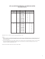
1
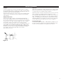
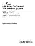
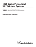
1600 Series Professional
UHF Wireless Systems
ATW-1661 UniPak™ Transmitter System
ATW-1662 Handheld Dynamic Microphone System
ATW-1663 Handheld Condenser Microphone System
Installation and Operation
Professional UHF Wireless Systems
Installation and Operation
This device complies with EN300 422-1, EN301 489-09
(EMC) and EN60065.
The ATW-R160, ATW-T161, ATW-T162 and ATW-T163 are
intended to be used in all countries of the European Union.
Please note :
Frequency usage is different for each country. Your AudioTechnica agent will have all the necessary details on the
available legal frequencies for your area.
CAUTION! Electrical shock can result from removal of the
receiver cover. Refer servicing to qualified service personnel.
No user-serviceable parts inside. Do not expose to rain or
moisture.
The circuits inside the receiver and transmitter have been
precisely adjusted for optimum performance and compliance with european regulations (R & TTE directive). Do not
attempt to open the receiver or transmitter. To do so will
void the warranty, and may cause improper operation.
Notice to individuals with implanted cardiac pacemakers
or AICD devices:
Any source of RF (radio frequency) energy may interfere with
normal functioning of the implanted device. All wireless
microphones have low-power transmitters (less than 0.05
watts output) which are unlikely to cause difficulty, especially if they are at least a few inches away. However, since a
“body-pack” mic transmitter typically is placed against the
body, we suggest attaching it at the belt, rather than in a shirt
pocket where it may be immediately adjacent to the medical
device. Note also that any medical-device disruption will
cease when the RF transmitting source is turned off. Please
contact your physician or medical-device provider if you have
any questions, or experience any problems with the use of
this or any other RF equipment.
Introduction
Thank you for choosing an Audio-Technica professional wireless
system. You have joined thousands of other satisfied customers
who have chosen our products because of their quality, performance and reliability. This Audio-Technica wireless microphone
system is the successful result of years of design and manufacturing experience.
Each 1600 Series wireless system provides a choice of PLL-synthesized UHF frequencies. Each wireless system includes a
receiver and either a body-pack or handheld transmitter.
Individual components are also available separately.
2
The ATW-R160 receiver features true diversity reception. Two
antennas feed two completely independent RF sections on
the same frequency; automatic logic circuitry continuously
compares and selects the superior received signal, providing
better sound quality and reducing the possibility of interference
and dropouts. Soft-touch controls provide convenient access
to a variety of functions, while an LCD information display
provides constant monitoring of system operation. The receiver
is half-width for a standard 1U 19" rack mount; rack-mount
adapters are included. Two receivers can be mounted side by
side, using an optional AT8616 joining-plate kit.
The versatile ATW-T161 UniPak™ body-pack transmitter has
both low- and high-impedance inputs plus a bias connection,
for use with dynamic and electret condenser microphones, as
well as Hi-Z instrument pickups.
The ATW-T162 handheld dynamic microphone/transmitter
features a hyper cardioid element created for professional livesound venues.
The ATW-T163 handheld condenser microphone/transmitter
features a cardioid element created for professional live-sound
venues and installations, such as use with inductive loop
systems.
Transmitters in the 1600 Series use two 1.5V AA batteries for
economical operation and wide availability.
Tone squelch system in the ATW-R160 receiver opens only
when a 1600 Series transmitter is detected, reducing the possibility of interference. As a result, 1600 Series transmitters and
receivers must be used together and should not be used with
components from other Audio-Technica wireless systems, or
with those of other manufacturers.
Please note that in multiple-system applications there must be
a transmitter-receiver combination set to a separate frequency
for each input desired (only one transmitter for each receiver).
Due to the wireless frequencies being within UHF TV frequency
bands, only certain operating frequencies may be useable in
a particular geographic area.
Please contact your National Radio Licensing Authority for
further information.
UK Users:
JFMG Limited
33-34 Alfred Place, London WC1E 7PD
TEL: 020 7299 8660 FAX: 020 7299 8661
e-mail: [email protected]
Receiver Installation
Location
For best operation the receiver should be at least 1 m above
the ground and at least 1 m away from a wall or metal surface
to minimise reflections. The transmitter should be at least 1 m
from the receiver, as shown in Figure A.
Keep antennas away from noise sources such as digital equipment, motors, automobiles and neon lights, as well as large
metal objects.
Output Connections
There are two audio outputs on the back panel: balanced
(32 mV) and unbalanced (52 mV). Use shielded audio cable for
the connection between the receiver and the mixer. If the input
of the mixer is a 1/4" jack, connect a cable from the 1/4" unbalanced audio output on the back of the receiver housing
to the mixer. If the input of the mixer is an XLR-type input, connect a cable from the balanced XLR-type audio output on the
back panel to the mixer. The two isolated audio outputs permit
simultaneous feeds to both unbalanced and balanced inputs.
For example, both a guitar amp and a mixer can be
driven by the receiver.
Antennas
Attach the included pair of UHF antennas to the antenna input
jacks. The antennas are normally positioned in the shape of a
“V” (both 45° from vertical) for best reception.
Antennas can be remotely located from the receiver. However,
due to signal loss in cables at UHF frequencies, use the
lowest-loss RF cables practical for any cable runs over 25 feet
(8 m ). RG8-type is a good choice. Use only copper-shielded
cable, not CATV-type foil-shielded wire. Audio-Technica offers
quality RF cables in four lengths, as well as remote antennas;
see the Optional System Accessories section on page 9.
Power Connections
Connect the supplied AT 220 ~ 240V, 50Hz AC adapter to the
DC power input on the back of the receiver. Operation of the
receiver is controlled by the front-panel Power switch.
Figure A
3
Receiver Controls and Functions
Front Panel Controls and Functions (Figure. B)
1. POWER SWITCH/INDICATOR: Press switch on, and the
"Power" indicator will light.
2. LCD WINDOW: Liquid Crystal Display indicates control
settings and operational readings. See Figure D for
examples.
3. TUNER OPERATION INDICATOR: Indicates which Tuner
(A or B) has the better reception and is in operation.
4. SET BUTTON: Activates access to Frequency/Scan
mode and sets or cancels selected function when used in
combination with CH SELECT/SCAN button (Item 5).5.
5. CH SELECT/SCAN BUTTON: Use in conjunction
with the SET button (Item 4) to select operation frequency
and scan function.
6. AF LEVEL CONTROL: Adjusts audio output level of both AF
Output jacks; maximum output is fully clockwise.
7. SQUELCH CONTROL: Adjusts level of noise-muting circuit
(preset at factory but can be adjusted as circumstances
warrant).
8. MOUNTING ADAPTERS: For mounting the receiver in any
standard 19" rack. Attach adapters to the receiver with the
screws supplied and remove the four receiver feet. (Use
optional AT8616 joining-plate kit to mount two ATW-R160
receivers side-by-side.)
9. PLL Lock indicator: This indicates Phased Lock Loop
frequency controlled oscillator has locked displayed
frequency.
Figure B
8
3
2
9
4
5
7
6
8
1
Rear Panel Controls and Functions (Figure C)
10. ANTENNA INPUT JACK: BNC-type antenna connector for
Tuner “B.” Attach the antenna directly, or extend it with a
low-loss antenna cable. See the “Antennas” section on
page 3 for more details.
11. ANTENNA INPUT JACK: Input for Tuner “A.” Attach the
antenna directly, or extend it with a low-loss antenna cable.
12. GROUND LIFT SWITCH: Disconnects the ground pin of the
balanced output jack (12) from ground. Normally, the switch
should be to the left (ground connected). If hum caused by
a ground loop occurs, slide switch to the right (ground
lifted).
13. BALANCED AUDIO OUTPUT JACK: XLRM-type connector.
A standard 2-conductor shielded cable can be used to
connect the receiver output to a balanced microphone-level
input on a mixer or integrated amplifier.
14. UNBALANCED AUDIO OUTPUT JACK: 1/4" phone jack. Can
be connected to an unbalanced aux-level input of a mixer,
guitar amp or tape recorder.
15. POWER INPUT JACK: Connect the DC plug from the
included AC adapter.
16. ATW-RA1 Rack-Mount Antenna kit mounting Holes: Mount
optional front-mount antenna kit ATW-RA1 on these holes.
Figure c
16
16
Power On/Off
To turn the receiver on, press the Power switch. The Power
light and the LCD window will come on after about 1-2
seconds. The operating channel number and frequency will be
displayed in the window after the power-up sequence. To turn
the receiver off, press the Power switch again.
How to Make Setting Changes
A. Select Frequency Manually
1. From the normal operating mode, press and hold the set
button until display flashes.
2. To select frequency, press CH SELECT/SCAN button once
at a time until desired channel is displayed (1 to 9, A to F).
3. (a) To select frequency, press and hold SET button until
display stops flashing.
(b) To cancel frequency selection, simply press the SET
button once. The receiver then returns to the normal
operation.
4
16
10
13
12 14
15
11
16
B. Select Open Frequency Scan Function
1. From the normal operating mode, press and hold the set
button until display flashes.
2. To select scan function, press and hold CH SELECT/SCAN
button, continue to hold until available frequency is
automatically displayed.
3. (a) To select frequency, press and hold SET button until
display stops flashing.
(b) To cancel frequency selection, simply press the SET
button once. The receiver then returns to the normal
operation without making any changes.
Figure D
ANT A
ANT B
AF
RF
CHANNEL
840.125 MHZ
Transmitter Setup
Battery Selection and Installation
Each transmitter uses two 1.5V AA batteries, not included.
Alkaline type is recommended. Always replace both batteries.
Make certain the transmitter power is Off before replacing
batteries.
UniPak™ Transmitter Battery Installation
1. Slide off the battery cover as shown in Figure E.
2. Observe correct polarity as marked inside the battery
compartment, and carefully insert two fresh 1.5V AA
alkaline batteries.
3. Replace the Battery cover (Figure.E)
Figure E
Microphone Guitar Trimmer
(GT)
Trimmer (MT)
Battery Condition Indicator
The Green Battery condition indicator(Figure I/ J) should light
strongly with a fresh battery. As the battery weakens, the
indicator will glow Red. When the Indicator becomes Red, there
is little life left in the battery. Replace it at once for continued
operation of the transmitter.
Battery Save Switch
ATW-T161 Transmitter features RF Lo / Hi Power switch
(Figure E). As supplied, the switch is set in the Lo (Low)
position for the maximum battery life. Hi(High) position can be
selected for maximum range (Note range decreases when the
switch is set at Lo position.)
Special Note: If accessing de-regulated frequencies between
863 to 865MHz(Ch. C to F), ATW-T161 must be set to RF
Low.
Figure I
Power Switch
OFF / ON
Figure J
Battery Condition
Indicator
Power Switch
ON / OFF
Channel Selector
Battery-Save Switch Battery Polarity
(under screwdriver clip)
Diagram
Input
Connector
Figure F
Antenna
Battery Condition
Indicator
UniPak Transmitter Input Connection
Handheld Transmitter Battery Installation
1. While holding the upper part of the transmitter body just
below the ball-screen, unscrew the lower body cover and
slide downward to remove and expose battery
compartment.
2. Be certain to observe correct polarity as marked inside
the battery compartment (Figure G) and carefully insert
two fresh 1.5V AA alkaline batteries. Make certain the
batteries are fully seated in the battery compartment.
3. Replace the lower body cover. Do not overtighten.
Figure G
Connect an audio input device (microphone or guitar cable)
to the audio input connector on the bottom of the transmitter.
A number of Audio-Technica professional microphones and
cables are available separately, pre-terminated with a UniPak
input connector (see “Optional System Accessories” on
page 9).
Transmitting Antenna
The UniPak transmitter includes a permanently-attached
flexible antenna. For best results, allow the antenna to hang
freely and full length from the bottom of the transmitter. If the
received signal is marginal, experiment with different transmitter positions on your body or instrument; or try repositioning
the receiver. Do not attempt to remove, replace or change
the length of the transmitting antenna.
The antenna for the ATW-T162 and ATW-T163 handheld
transmitters are located at the bottom of the units. For the
best results, hold the Microphone naturally around the
centre of the body.
Holding or otherwise covering antenna housing may affect
operating range.
Battery Polarity
Diagram
Figure H
Channel Selector
Gain Trimmer
Screwdriver
5
System Operation
Switch on the receiver. Do not switch on the transmitter yet.
Receiver Squelch
Selecting/Setting Frequency
It’s usually best to start by setting the receiver’s frequency to
determine there is no local interference on that frequency.
Then, always make certain to set the transmitter to the receiver’s exact frequency. The receiver’s Tone Lock system squelches the audio only, permitting any RF energy on the frequency to
show on the “RF” bar-meter.
The 1600 Series employs a Tone Lock squelch system that provides enhanced rejection of RF interference. The squelch control
on the front panel of the receiver is preset at the factory, but
can be adjusted if you are using the system in a high RF interference area. This adjustment can cause a reduction in the useable range of the wireless transmitter, so set the control to the
lowest position which reliably mutes the unwanted RF signals.
Receiver On…
The Power switch indicator and the LCD window will light up,
the normal-operation LCD display will appear after 1-2 seconds
(Figure D). If any of the bars show in the “RF” bar-graph meter,
there may be RF interference in the area. If this occurs, select
another frequency as explained below.
Input Level Adjustment
An input trimmer control (Trim) in the transmitters enables you
to maximize performance for a particular microphone or guitar
sensitivity, or to adjust for different acoustic input levels.
How to Make Setting Changes
A. Select Frequency Manually
1. From the normal operating mode, press and hold the set
button until display flashes.
2. To select frequency, press CH SELECT/SCAN button once
at a time until desired channel is displayed (1 to 9, A to F).
3. (a) To select frequency, press and hold SET button until
display stops flashing.
(b) To cancel frequency selection, simply press the SET
button once. The receiver then returns to the normal
operation.
B. Select Open Frequency Scan Function
1. From the normal operating mode, press and hold the set
button until display flashes.
2. To select scan function, press and hold CH SELECT/SCAN
button, continue to hold until available frequency is
automatically displayed.
3. (a) To select frequency, press and hold SET button until
display stops flashing.
(b) To cancel frequency selection, simply press the SET
button once. The receiver then returns to the normal
operation without making any changes.
Setting Transmitter Frequency
ATW-T161
Slide the Battery cover off and use screwdriver provided to set
the channel switch to the same channel selected on the receiver.
ATW-T162, ATW-T163
While holding the upper part of the transmitter body just below
the ball-screen, unscrew lower body cover, slide downward and
remove to expose battery compartment.
Use screwdriver provided to set the channel switch to the
same channel selected on the receiver.
6
CAUTION! The small trimmer controls are delicate; use
only the supplied screwdriver. Do not force the trimmers
beyond their normal 190 o range of rotation.
Return the screwdriver to its storage clip when not in use.
Setting Levels
Correct adjustment of transmitter audio input, receiver audio
output, and mixer/amplifier input and output levels is important
for optimum system performance.
Adjusting Input Level - UniPak Transmitter
Slide the battery cover off the top part of transmitter and
remove the screwdriver from its clip (Figure E). Gently turn the
"MT" (mic trimmer) and "GT" (guitar trimmer) control to their full
counterclockwise positions (marked “Lo”).
• Microphone: Adjusting input level
While speaking /singing into the microphone at typically-loud
levels, carefully turn the MT control clockwise while
watching the receiver’s AF Level indicator. Increase the Trim
control setting until the maximum audio output of the mic
lights about three or four units on the receiver's AF Level
indicator. Do not set the level too high. At normal audio levels,
only the first two or perhaps three units should light.
(When using a microphone, return the GT control setting to
minimum)
• Guitar/Instrument: Adjusting input level
While playing at typically-loud levels, carefully turn the GT
control clockwise while watching the receiver’s AF Peak
indicator. Increase the Trim control setting until the maximum
audio output of the mic lights about three or four units on the
receiver's AF Level indicator. Do not set the level too high.
After adjusting input level, return the screwdriver to its clip and
reinstall the battery cover. No further transmitter gain adjustments should be needed, as long as the input device and the
acoustic input level are not changed.
System Operation
Adjusting Input Level - Handheld Transmitter
Unscrew the lower body cover and slide it downward, exposing
the screwdriver and Trim control (Figure G and H). Remove the
screwdriver and gently turn the Trim control marked "VR" (variable resistor) to its full counterclockwise position.
While speaking /singing into the microphone at typically loud
levels, carefully turn the VR control clockwise while
watching the receiver’s AF Level indicator. Increase the VR control setting until the maximum audio output of the mic lights
three or four units on the receiver's AF Level indicator. Do not
set the level too high. At normal audio levels, only the first two
or three units should light.
(Continued)
RF Interference
Please note that wireless frequencies are shared with other
radio services. According to the National Communication
Authority, “Wireless microphone operations are unprotected
from interference from other licensed operations in the band. If
any interference is received by any Government or nonGovernment operation, the wireless microphone must cease
operation...”
If you need assistance with operation or frequency selection,
please contact your dealer.
Extensive wireless information is also available on the
Audio-Technica US Web site at www.audio-technica.com
Return the screwdriver to its clip and close and secure the
lower body. No further transmitter gain adjustments should
be needed, as long as the acoustic input does not change
significantly.
RF Power Adjustment
ATW-T161 RF power may be set to RF "Hi” (20 mW nominal) or
RF "Lo” (10 mW nominal) via battery save switch (Figure E).
The default setting is RF "Lo”. While the RF "Hi” setting normally provides maximum operating range, the RF "Lo” setting will
help extend battery life. The RF "Lo” setting may also be preferred in multi-channel systems, or when operating very close
to the receiver, to reduce the possibility of interference or
overload.
Special Note: If accessing de-regulated frequencies between
863 to 865MHz(Ch. C to F), ATW-T161 must be set to RF
Low.
Ten Tips to Obtain the Best Results
1. Use only fresh alkaline batteries. Do not use “general
purpose” (carbon-zinc) batteries.
6. The receiver and transmitter must be set to the same
frequency.
2. Position the receiver so that it has the fewest possible
obstructions between it and the normal location of the
transmitter. Line-of-sight is best.
7. A receiver cannot receive signals from two transmitters
at the same time.
3. The transmitter and the receiver should be as close
together as conveniently possible, but no closer than
three feet (1 m).
4. Avoid placing the receiver in a low or shielded location
where the transmitter and receiver antennas are not
visible to each other. If necessary, use remotely-located
receiver antennas.
5. Avoid placing the receiver near computers or other RF
generating equipment.
8. Do not obstruct the handheld transmitter’s antenna
(located at the base) or attached body-pack transmitter’s
antenna with your hands.
9. You need to change frequencies 1) when a strong
interference signal is received, 2) when audio quality is
poor due to weak RF, or 3) during multiple-system
operation in order to select an interference-free
frequency.
10. Turn the transmitter off when not in use. Remove the
batteries if the transmitter is not to be used for a period
of time.
7
Specifications†
OVERALL SYSTEM
UHF Operating Frequency *
Number of Channels
Frequency Stability
Modulation Mode
Normal Deviation
Operating Range
Operating Temperature Range
Frequency Response
ATW-R160 RECEIVER
Receiving System
Image Rejection
Signal-to-noise Ratio
Total Harmonic Distortion
Sensitivity
Intermediate Frequency
Audio Output
Unbalanced:
Balanced:
Output Connectors
Unbalanced:
Balanced:
Power Supply
Dimensions
Weight
Accessories Included
EX: 795.500 to 819.025 MHz
UK: 840.125 to 864.375 MHz
16
±0.005%, Phase Lock Loop frequency
control
FM
±10 kHz
100 m typical
41° F (5° C) to 113° F (45° C)
70 Hz to 15 kHz
Dual independent receivers, automaticswitching diversity
55 dB nominal
105 dB at 22.5 kHz deviation
(IEC-weighted), maximum modulation
36 kHz
≤1% (10 kHz deviation at 1 kHz)
15 dBµV (S/N 60 dB at 22.5 kHz deviation,
IEC-weighted)
65.75 MHz, 10 MHz
52 mV (at 1 kHz, ±5 kHz deviation,
10k ohm load)
32 mV (at 1 kHz, ±5 kHz deviation,
10k ohm load)
1
/4" TS (“mono”) phone jack
XLRM-type
12-18V DC, 500 mA external supply,
center positive.
210.0 mm)W x 49.0 mm H
x 195.0 mm D
2.4 lbs (1.1 kg)
Two flexible UHF antennas; rack-mount
adapters
ATW-T161 UNIPAK™ TRANSMITTER
RF Power Output **
According to National Regulations
Spurious Emissions
ETS 300 422-2
Dynamic Range
≥110 dB, A-weighted
Input Connections
High impedance, low impedance, bias
Batteries (not included)
Two 1.5V AA alkaline
Current Consumption
160 mA, typical
Battery Life
Approximately 6 hours (High); 8 hours
(Low), depending on battery type and
use pattern
Dimensions
65.0 mm W x 87.0 mm H x 24.0 mm D
Net Weight (without batteries)
90 grams
ATW-T162, ATW-T163 HANDHELD TRANSMITTER
RF Power Output**
According to National Regulations
Spurious Emissions
ETS 300 422-2
Dynamic Range
≥110 dB, A-weighted
Microphone Element
ATW-T162:
Dynamic Hyper-cardioid (unidirectional)
ATW-T163:
Condenser Cardioid (unidirectional)
Batteries (not included)
Two 1.5V AA alkaline
Current Consumption
170 mA, typical
Battery Life
Approximately 8 hours, depending on
battery type and use pattern
Dimensions
240.0 mm long, 48.0 mm diameter
Net Weight (without batteries)
240 grams
Accessory Included
AT8456a stand clamp
†
*
**
Carrier frequency, maximum deviation and output power depends on
government regulations.
Complies to the R & TTE Directive
Specifications are subject to change without notice.
0700
8
Optional System Accessories
WIRELESS ESSENTIALS™ MICROPHONES AND CABLES
All Wireless Essentials accessories are terminated for use with ATW-T1600
and other UniPak™ transmitters.
AT829cW
Miniature cardioid condenser lavalier microphone.
Includes clothing clip and windscreen.
MT830cW
Subminiature omnidirectional condenser lavalier
microphone. Includes clothing clip and windscreen.
MT830cW-TH “Theatre” model, same as MT830cW except beige colour
mic and cable for concealment.
AT831cW
Miniature cardioid condenser lavalier microphone.
Includes clothing clip and windscreen.
AT851cW
Surface-mount wide-range semi-cardioid condenser
microphone.
AT857AMLcW 19" gooseneck cardioid microphone.
Mounts to 5/8"-27 thread. Includes windscreen.
AT889cW
Headworn noise-cancelling condenser microphone.
Includes windscreen and cable clip.
ATM35cW
Cardioid condenser instrument microphone.
Includes AT8418 clip-on instrument mount.
ATM73cW
Headworn cardioid condenser microphone.
Includes windscreen.
ATM75cW
Headworn cardioid condenser microphone.
Includes windscreen.
PRO 8HEcW
Headworn hypercardioid dynamic microphone.
Includes windscreen and cable clip.
PRO 35xcW
Cardioid condenser instrument microphone.
Includes AT8418 clip-on instrument mount.
AT8319
Hi-Z instrument/guitar cable with 1/4" phone plug.
AT8317
Connecting cable for UniPak transmitter with an XLRF-type
input connector, for Lo-Z microphones with XLRM-type
output terminations.
RECEIVER ACCESSORIES
AT8616
Joining-plate kit allows rack-mounting two ATW-R160
receivers side-by-side in a single (1U) 19" rack space.
ATW-A20
Pair of UHF ground-plane antennas with 5/8"-27 thread for
mounting to microphone stands, etc. For use with
ATW-R160 receivers. Takes RF cables with BNC
connectors, not included; see RF Cables below.
ATW-A49
Pair of UHF wide-band directional LPDA (log periodic dipole
array) antennas provide enhanced signal pickup for UHF
wireless systems throughout a wide band range
(440-900 MHz). Each antenna paddle is matched to
50 ohms impedance with and integral hi-quality low -loss
BNC connector, 6dB gain. For permanent or temporary
installation; mounts to 5/8"-27 threads.
AEW-DA800EU UHF ( DA800: 795-820, DA860: 840-865 MHz) active
AEW-DA860UK unity-gain antenna distribution system provides two
“1-in, 4-out” RF channels; connects a pair of antennas to
as many as four diversity receivers. A cascade ouput is
provided as a directional coupler to drive additional
distribution amps. Includes four DC interconnect cables to
power up to four receivers, eight RF output cables and two
rack-mount adapters. Mounts in a single (1U) 19" rack
space. For use with ATW-R160 EX (ATW-DA800) and
ATW-R160 UK (AEW-DA860) receivers.
ATW-RA1
Rack-mount antenna kit brings antenna inputs to the front of
receiver for ease of setup, or when receiver is enclosed in a
metal rack. Includes a pair of extendable antennas. NOTE:
Two adapter kits are required when mounting two receivers
side-by-side in a single 19" rack space.
RF Cables
Low-loss design, 50 ohm impedance, with BNC-to-BNC
connectors:
AC12
RG58-type cable (12')
AC25
RG8-type cable (25')
AC50
RG8-type cable (50')
AC100 RG8-type cable (100')
TRANSMITTER ACCESSORIES
AT8114
Foam windscreen for handheld transmitter.
AT8141
Water-resistant pouch for UniPak transmitter.
AT8390
Shielded audio cable with 1/4" to 1/4" phone plugs.
Available in a variety of lengths.
(Also available with one straight and one 90° phone plug
as the AT8316.)
AT8456a
Stand clamp for handheld transmitter, 5/8"-27 threads.
9
Troubleshooting Guide
Receiver is not on (LCD window does not light).
• Receiver Power switch is not pressed in.
• Small DC power cord from included in-line power supply
is not plugged into jack on back of receiver.
• The power supply is not plugged into AC power
outlet.
• AC power is not present at the AC outlet.
Receiver is on (LCD window lights)
• No sound:
✓“RF” and "AF" level meters both show good signals.
• AF Level control on front of receiver not turned up
(clockwise). [See p. 4.]
Note: If the “AF” level meter shows a good signal on the
receiver when the transmitter is receiving audio input,
and the AF Level control is turned up, then the problem
is in connections to, or control settings on the mixer,
amplifier, etc.
✓Only “RF” level meter shows good signal; no “AF”
signal.
• No sound input to mic.
• ATW-T161 body-pack only: Wrong input trim selected
(“GT”or “MIC”). [See p. 5.]
Receiver is on (LCD window lights)
• No sound:
✓“RF” and “AF” level meters both show good signals.
• The transmitter audio level is too high
[See p. 4 & 5]
✓Neither the “RF” nor the “AF” level meter shows any
signal.
• Receiver antennas not connected.
• Transmitter is turned off.
• Transmitter is set to a different frequency.
• Transmitter batteries are dead or missing.
Receiver is on (LCD window lights)
• Distorted sound:
✓“RF” and/or “AF” level meters may show good signals.
• The transmitter audio level is too high.
[See p. 6 & 7.]
• Received RF level may be too low (only one or two bars).
• Batteries may be weak; check “BATT” condition
indicator.
[See p. 5]
10
Momentary loss of sound/noisy sound as transmitter is
moved around performing area.
• Transmitter and receiver antennas not in line-of-sight
(or perhaps too far apart). Adjust positions of units so
they are visible to each other/closer together.
If problem persists. use remote antennas located closer
to the transmitter location.
• Signal blockage or interference from large metal objects,
other wireless units located too close and/or on
incompatible frequencies, computer or lighting
equipment.
• Squelch setting may be set “tighter” than it needs to
be.
[See p. 6]
With transmitter on, received signal is noisy or contains
extraneous sounds.
• Batteries may be weak. Check “Battery condition
indicator and “RF” meter level.
• Local TV transmissions on this frequency.
• Nearby sources of RF interference, such as computers,
lighting equipment, etc.
• Two transmitters may be operating on the same
frequency. Locate and turn one off or change its
frequency.
• In multiple-system use, two (or more) incompatible
frequencies may have been selected. Refer to the
suggested multi-channel frequency combinations.
on supplement sheet,
ATW-1600 SERIES PROFESSIONAL UHF WIRELESS SYSTEM
FOR USE IN THE UK
Cannel
No.
Band
0
Co-ordinate
1
2
3
4
5
6
Shared
7
8
9
A
B
C
De-regulated
D
E
F
Frequency
(MHZ)
840.125
840.375
841.125
841.375
844.250
845.500
854.900
855.275
856.575
857.625
860.900
861.200
863.125
863.375
864.125
864.375
Group
1
O
O
O
O
O
O
O
O
2
O
O
O
O
O
O
O
O
O
Notes:
Frequencies listed in Group 1 should be used for Open Frequency Scan Function.
Please note that Band UK antenna colour code is grey
11
ATW-1600 SERIES PROFESSIONAL UHF WIRELESS SYSTEM
STATEMENT OF COMPLIANCE FOR USE IN THE UK
Usage :The ATW-T161 and ATW-T162 are intended to be used in all countries of the European Union.
Please note : Frequency usage is different for each country. Your Audio-Technica agent will have all the necessary
details on the available legal frequencies for your area.
Statement of Compliance :Audio-Technica hereby declares that the ATW-T161 and ATW-T162 are in compliance with the essential
requirements and other relevant provisions of Directive 1999/5/EC.
Audio-Technica vakuuttaa täten että ATW-T161, ATW-T162 tyyppinen laite on direktiivin 1999/5/EY oleellisten
vaatimusten ja sitä koskevien direktiivin muiden ehtojen mukainen.
Hierbij verklaart Audio-Technica dat het toestel ATW-T161, ATW-T162 in overeenstemming is met de essentiële
eisen en de andere relevante bepalingen van richtlijn 1999/5/EG
Bij deze verklaart Audio-Technica dat deze ATW-T161, ATW-T162 voldoet aan de essentiële eisen en aan de
overige relevante bepalingen van Richtlijn 1999/5/EC.
Par la présente Audio-Technica déclare que l'appareil ATW-T161, ATW-T162 est conforme aux exigences
essentielles et aux autres dispositions pertinentes de la directive 1999/5/CE
Par la présente, Audio-Technica déclare que ce ATW-T161, ATW-T162 est conforme aux exigences essentielles et
aux autres dispositions de la directive 1999/5/CE qui lui sont applicables
Härmed intygar Audio-Technica att denna ATW-T161, ATW-T162 står I överensstämmelse med de väsentliga
egenskapskrav och övriga relevanta bestämmelser som framgår av direktiv 1999/5/EG.
Undertegnede Audio-Technica erklærer herved, at følgende udstyr ATW-T161, ATW-T162 overholder de
væsentlige krav og øvrige relevante krav i direktiv 1999/5/EF
Hiermit erklärt Audio-Technica, dass sich dieser/diese/dieses ATW-T161, ATW-T162 in Übereinstimmung mit den
grundlegenden Anforderungen und den anderen relevanten Vorschriften der Richtlinie 1999/5/EG befindet".
(BMWi)
Hiermit erklärt Audio-Technica die Übereinstimmung des Gerätes ATW-T161, ATW-T162 mit den grundlegenden
Anforderungen und den anderen relevanten Festlegungen der Richtlinie 1999/5/EG. (Wien)
ΜΕ ΤΗΝ ΠΑΡΟYΣΑ Audio-Technica ∆ΗΛΩΝΕΙ ΟΤΙ ATW-T161, ATW-T162 ΣYΜΜΟΡΦΩΝΕΤΑΙ ΠΡΟΣ ΤΙΣ
ΟYΣΙΩ∆ΕΙΣ ΑΠΑΙΤΗΣΕΙΣ ΚΑΙ ΤΙΣ ΛΟΙΠΕΣ ΣXΕΤΙΚΕΣ ∆ΙΑΤΑΞΕΙΣ ΤΗΣ Ο∆ΗΓΙΑΣ 1999/5/ΕΚ
Con la presente Audio-Technica dichiara che ATW-T161, ATW-T162 è conforme ai requisiti essenziali ed alle altre
disposizioni pertinenti stabilite dalla direttiva 1999/5/CE.
Por medio de la presente Audio-Technica declara que el ATW-T161, ATW-T162 cumple con los requisitos
esenciales y cualesquiera otras disposiciones aplicables o exigibles de la Directiva 1999/5/CE
Audio-Technica declara que este ATW-T161, ATW-T162 está conforme com os requisitos essenciais e outras
disposições da Directiva 1999/5/CE
A full copy of the declaration of conformity with directive 1999/5/EC may be obtained from –
Audio-Technica Limited
Old Lane, Leeds, LS11 8AG
U.K
12
ATW-1600 SERIES PROFESSIONAL UHF WIRELESS SYSTEM
FOR USE IN THE EU
Band
A
B
Cannel
No.
0
1
2
3
4
5
6
7
8
9
A
B
C
D
E
F
Frequency
(MHZ)
795.500
796.000
797.900
800.975
802.025
807.500
809.500
814.500
799.400
801.100
801.425
804,825
805.150
813.700
817.425
819.025
Group
1
O
O
O
O
O
O
O
O
2
O
O
O
O
O
O
O
O
Operation of this system in France is restricted to Band A only.
Notes:
1. Above two bands are designed for general use in EU countries. Usable spectrum can change from country to
country. Please contact your authorized Audio-Technica distributor or National Radio Licencing Authority for
further information.
2. How to Choose band A or B as open frequency scan group:- prior to selecting Open frequency Scan function,
use manual frequency selection method and set a start frequency from band A (Group A scan) or start
frequency from band B (group B Scan).
Please note that Band EU antenna colour code is black
13
ATW-1600 SERIES PROFESSIONAL UHF WIRELESS SYSTEM
STATEMENT OF COMPLIANCE FOR USE IN THE EU
Usage :The ATW-T161 and ATW-T162 are intended to be used in all countries of the European Union.
Please note : Frequency usage is different for each country. Your Audio-Technica agent will have all the necessary
details on the available legal frequencies for your area.
Statement of Compliance :Audio-Technica hereby declares that the ATW-T161 and ATW-T162 are in compliance with the essential
requirements and other relevant provisions of Directive 1999/5/EC.
Audio-Technica vakuuttaa täten että ATW-T161, ATW-T162 tyyppinen laite on direktiivin 1999/5/EY oleellisten
vaatimusten ja sitä koskevien direktiivin muiden ehtojen mukainen.
Hierbij verklaart Audio-Technica dat het toestel ATW-T161, ATW-T162 in overeenstemming is met de essentiële
eisen en de andere relevante bepalingen van richtlijn 1999/5/EG
Bij deze verklaart Audio-Technica dat deze ATW-T161, ATW-T162 voldoet aan de essentiële eisen en aan de
overige relevante bepalingen van Richtlijn 1999/5/EC.
Par la présente Audio-Technica déclare que l'appareil ATW-T161, ATW-T162 est conforme aux exigences
essentielles et aux autres dispositions pertinentes de la directive 1999/5/CE
Par la présente, Audio-Technica déclare que ce ATW-T161, ATW-T162 est conforme aux exigences essentielles et
aux autres dispositions de la directive 1999/5/CE qui lui sont applicables
Härmed intygar Audio-Technica att denna ATW-T161, ATW-T162 står I överensstämmelse med de väsentliga
egenskapskrav och övriga relevanta bestämmelser som framgår av direktiv 1999/5/EG.
Undertegnede Audio-Technica erklærer herved, at følgende udstyr ATW-T161, ATW-T162 overholder de
væsentlige krav og øvrige relevante krav i direktiv 1999/5/EF
Hiermit erklärt Audio-Technica, dass sich dieser/diese/dieses ATW-T161, ATW-T162 in Übereinstimmung mit den
grundlegenden Anforderungen und den anderen relevanten Vorschriften der Richtlinie 1999/5/EG befindet".
(BMWi)
Hiermit erklärt Audio-Technica die Übereinstimmung des Gerätes ATW-T161, ATW-T162 mit den grundlegenden
Anforderungen und den anderen relevanten Festlegungen der Richtlinie 1999/5/EG. (Wien)
ΜΕ ΤΗΝ ΠΑΡΟYΣΑ Audio-Technica ∆ΗΛΩΝΕΙ ΟΤΙ ATW-T161, ATW-T162 ΣYΜΜΟΡΦΩΝΕΤΑΙ ΠΡΟΣ ΤΙΣ
ΟYΣΙΩ∆ΕΙΣ ΑΠΑΙΤΗΣΕΙΣ ΚΑΙ ΤΙΣ ΛΟΙΠΕΣ ΣXΕΤΙΚΕΣ ∆ΙΑΤΑΞΕΙΣ ΤΗΣ Ο∆ΗΓΙΑΣ 1999/5/ΕΚ
Con la presente Audio-Technica dichiara che ATW-T161, ATW-T162 è conforme ai requisiti essenziali ed alle altre
disposizioni pertinenti stabilite dalla direttiva 1999/5/CE.
Por medio de la presente Audio-Technica declara que el ATW-T161, ATW-T162 cumple con los requisitos
esenciales y cualesquiera otras disposiciones aplicables o exigibles de la Directiva 1999/5/CE
Audio-Technica declara que este ATW-T161, ATW-T162 está conforme com os requisitos essenciais e outras
disposições da Directiva 1999/5/CE
A full copy of the declaration of conformity with directive 1999/5/EC may be obtained from –
Audio-Technica Limited
Old Lane, Leeds, LS11 8AG
U.K
14
One-Year Limited Warranty
Audio-Technica microphones and accessories purchased in the EU are warranted for one year from date of purchase by Audio-Technica Limited to be
free of defects in materials and workmanship. In event of such defect, product will be repaired promptly without charge or, at our option, replaced
with a new product of equal or superior value if delivered to Audio-Technica Limited, prepaid together with the proof of purchase. Prior approval from
Audio-Technica Limited is required for return. This warranty excludes defects due to normal wear, abuse, shipping damage, or failure to use product
in accordance with instructions. This warranty is void in the event of unauthorized repair or modification.
For return approval and shipping information, contact the Service Department,
Audio-Technica Limited. Tel: +44 (0)113 277 1441
Outside the EU, please contact your local dealer for warranty details.
For future reference, please record your system information here:
Receiver
ATW-R160
S/N_____ _____ _____ _____ _____ _____ _____
Serial Number appears on the FCC label on the bottom of the receiver.
Transmitter
ATW-T161
S/N_____ _____ _____ _____ _____ _____ _____
Serial Number appears in a recess in the battery compartment of the transmitter..
ATW-T162
S/N_____ _____ _____ _____ _____ _____ _____
Serial Number appears in a recess in the battery compartment of the transmitter.
ATW-T162
S/N_____ _____ _____ _____ _____ _____ _____
Serial Number appears in a recess in the battery compartment of the transmitter.
Visit our Web Site!
www.audio-technica.co.uk
|
|
Audio-Technica Ltd. Email: [email protected] Web: www.audio-technica.co.uk
Audio-Technica Europe A Division of Audio Technica Ltd.
Email: [email protected] Web: www.audio-technica-europe.com
|
|
|
|
|
Technica House Royal London Industrial Estate Old Lane Leeds LS11 8AG
Tel: +44 (0)113 277 1441 Fax: +44 (0)113 270 4836
|
| UK