1
M3000 Portable Bar Code Reader
User's Guide
Copyright American Microsystems, Ltd. 1992, 1993. All rights reserved.
Acknowledgements
IBM, PC and PS/2 are registered trademarks of International Business Machines Corporation.
MS-DOS is a registered trademark of Microsoft Corporation.
FCC NOTICE
Warning: This equipment generates, uses and can radiate radio frequency energy and if not installed and used in
accordance with the instruction manual, may cause interference to radio communications. It has been tested and found to
comply with the limits for a Class A computing device pursuant to Subpart J of Part 15 FCC Rules, which are designed to
provide reasonable protection against such interference when operated in a commercial environment. Operation of this
equipment in a residential area is likely to cause interference in which case the user at his own expense will be required to
take whatever measures may be required to correct the interference.
Printed and bound in the United States of America.
2190 Regal Parkway Euless, TX 76040
(817) 571-9015 (800) 648-4452 FAX (817) 685-6232
Rev 2.19
Contents
Overview
ix
Introduction ....................................................................................................................................................ix
Portable Mode .................................................................................................................................................x
Non Portable Modes ........................................................................................................................................x
Communications..............................................................................................................................................x
Style Conventions Used in This Manual ........................................................................................................xi
Text: .................................................................................................................................................xi
Symbols:...........................................................................................................................................xi
Installation
1-1
Portable Mode Installation .......................................................................................................................... 1-1
Keyboard Wedge Installation ...................................................................................................................... 1-2
Serial Wedge Installation ............................................................................................................................ 1-3
RS-232 Serial Installation............................................................................................................................ 1-4
Modem Installation...................................................................................................................................... 1-5
Installing Input Devices............................................................................................................................... 1-5
Keyboard
2-1
Introduction ................................................................................................................................................. 2-1
Keyboard Layout......................................................................................................................................... 2-2
Other Key Combinations............................................................................................................................. 2-3
Function Reference
3-1
Introduction ................................................................................................................................................. 3-1
Arrow Keys ................................................................................................................................... 3-1
Calculator ...................................................................................................................................... 3-1
CLEAR.......................................................................................................................................... 3-2
ERASE .......................................................................................................................................... 3-2
HELP............................................................................................................................................. 3-4
INSREC ........................................................................................................................................ 3-5
RECALL ....................................................................................................................................... 3-5
SEARCH....................................................................................................................................... 3-5
STATUS........................................................................................................................................ 3-5
STORE .......................................................................................................................................... 3-6
TIME............................................................................................................................................. 3-6
Quick Start - Basic Operations
4-1
i
M3000 Portable Bar Code Reader User's Guide
Startup - Portable Mode............................................................................................................................... 4-1
Loading a Built-in Program into RAM........................................................................................................ 4-1
Using the INPUT Function.......................................................................................................................... 4-3
Selecting a Program..................................................................................................................................... 4-3
Creating a New Data File ............................................................................................................................ 4-3
Entering Data into a Data File ..................................................................................................................... 4-4
Using the Built-in CALC Function ............................................................................................................. 4-4
Exiting and Saving a Data File .................................................................................................................... 4-5
Edit/Review a Data File............................................................................................................................... 4-5
Automatic Input........................................................................................................................................... 4-7
Startup - Non Portable Mode....................................................................................................................... 4-7
Keyboard Wedge Mode............................................................................................................................... 4-8
Serial Wedge Mode ..................................................................................................................................... 4-8
RS-232 Serial Mode .................................................................................................................................... 4-9
Scanning Bar Codes .................................................................................................................................. 4-11
Wand Scanning.......................................................................................................................................... 4-11
Scanning with Trigger Type Lasers........................................................................................................... 4-11
Scanning with the MS941 Triggerless Laser............................................................................................. 4-13
CCD Scanning........................................................................................................................................... 4-14
Slot Reader (Badge Reader) ...................................................................................................................... 4-15
Programming
5-1
Introduction to Programming ...................................................................................................................... 5-1
Selecting Existing Programs........................................................................................................................ 5-1
Erasing a Program ....................................................................................................................................... 5-2
Exiting a Program........................................................................................................................................ 5-2
Programming Tutorial ................................................................................................................................. 5-3
Summary of Built-in Programs.................................................................................................................. 5-12
Programming Prompts - Start of Program ................................................................................................. 5-14
Creating a New Program ............................................................................................................. 5-14
SOF Text ..................................................................................................................................... 5-15
SOF Delay................................................................................................................................... 5-15
EOF Text..................................................................................................................................... 5-15
EOF Delay................................................................................................................................... 5-15
Use Receive Data Files Only?..................................................................................................... 5-16
Allow Append to End of File? .................................................................................................... 5-16
ii
Contents
Programming Prompts - Input Definition Sequence.................................................................................. 5-16
Header Input?.............................................................................................................................. 5-16
New Screen? ............................................................................................................................... 5-16
Input Type ................................................................................................................................... 5-17
Prompt......................................................................................................................................... 5-17
Stamp Commands ....................................................................................................................... 5-17
Exhibit Text................................................................................................................................. 5-18
Screen Usage Parameters ............................................................................................................ 5-18
Str Row ....................................................................................................................................... 5-19
Str Col ......................................................................................................................................... 5-19
End Row...................................................................................................................................... 5-19
End Col ....................................................................................................................................... 5-19
Data Input Parameters ................................................................................................................. 5-21
Input Size Max ............................................................................................................................ 5-21
Input Size Min............................................................................................................................. 5-21
Require Input?............................................................................................................................. 5-21
Auto Advance?............................................................................................................................ 5-21
Display Pattern ............................................................................................................................ 5-22
Input Mask .................................................................................................................................. 5-22
Shift Input Data to Upper Case ................................................................................................... 5-23
Input Source K, B, S, or X .......................................................................................................... 5-23
Bar Code Types........................................................................................................................... 5-23
Bar Code Append........................................................................................................................ 5-24
Bar Code Auto Advance ............................................................................................................. 5-24
Allow Duplicate Inputs ............................................................................................................... 5-24
Default Data ................................................................................................................................ 5-24
Lookup Tbl/File .......................................................................................................................... 5-25
Enable Input Transmit................................................................................................................. 5-25
Data Output Parameters .............................................................................................................. 5-25
Output Format V,L or R.............................................................................................................. 5-25
Prefix........................................................................................................................................... 5-25
Prefix Delay ................................................................................................................................ 5-26
Suffix........................................................................................................................................... 5-26
Suffix Delay ................................................................................................................................ 5-26
Setup Procedures
6-1
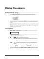
Introduction to Setup ................................................................................................................................... 6-1
Changing Setup ........................................................................................................................................... 6-1
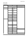
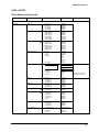
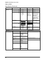
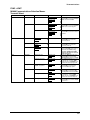
Setup Categories.......................................................................................................................................... 6-6
Date/Time...................................................................................................................................... 6-6
Non Portable Mode (Nonport. Mode) ........................................................................................... 6-7
Keyboard Wedge ............................................................................................................ 6-7
Serial Wedge................................................................................................................... 6-7
RS232 Serial ................................................................................................................... 6-7
Keyboard Wedge........................................................................................................................... 6-8
iii
M3000 Portable Bar Code Reader User's Guide
Type ................................................................................................................................ 6-8
Keyboard (Keybd) .......................................................................................................... 6-8
Output ............................................................................................................................. 6-8
Auto Caps ....................................................................................................................... 6-8
Caps Lock ....................................................................................................................... 6-9
Num Lock ....................................................................................................................... 6-9
Scan Set 3 ....................................................................................................................... 6-9
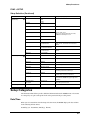
Serial Port...................................................................................................................................... 6-9
Protocol......................................................................................................................... 6-10
Output ........................................................................................................................... 6-10
Baud Rate...................................................................................................................... 6-10
Data Bits ....................................................................................................................... 6-10
Parity............................................................................................................................. 6-10
Stop Bits........................................................................................................................ 6-10
Character Delay ............................................................................................................ 6-11
Duplex........................................................................................................................... 6-11
Caps Lock ..................................................................................................................... 6-11
Num Lock ..................................................................................................................... 6-11
Serial Beep.................................................................................................................... 6-11
Auto Advance ............................................................................................................... 6-11
Bar Codes.................................................................................................................................... 6-12
CODE 39 ...................................................................................................................... 6-12
UPC............................................................................................................................... 6-12
EAN .............................................................................................................................. 6-13
UPC/EAN Addons (SUPPLEMENTS)......................................................................... 6-14
I 2 OF 5......................................................................................................................... 6-14
CODABAR................................................................................................................... 6-15
CODE 128 .................................................................................................................... 6-15
CODE 93 ...................................................................................................................... 6-16
MSI/Plessey .................................................................................................................. 6-16
Code 11......................................................................................................................... 6-17
Termination Character .................................................................................................. 6-17
Preamble ....................................................................................................................... 6-18
Postamble...................................................................................................................... 6-18
Bar Code Edit................................................................................................................ 6-18
Editing ............................................................................................................ 6-18
Lead Strip (Leading Strip) (0-30) ................................................................... 6-18
Trail Strip (Trailing Strip) (0-30) ................................................................... 6-18
Space Strip...................................................................................................... 6-18
iv
Contents
Code................................................................................................................ 6-19
Bar Code Beeper........................................................................................................... 6-19
Tone................................................................................................................ 6-19
Length............................................................................................................. 6-19
Laser/CCD Opts (Options) ........................................................................................... 6-19
Timeout........................................................................................................... 6-19
Trigger Off...................................................................................................... 6-19
Always Run .................................................................................................... 6-19
Read Delay (0.0 - 9.9 SEC) ............................................................................ 6-20
Other Options................................................................................................................ 6-20
Bar Code ID.................................................................................................... 6-20
Dupli Reads (Duplicate Reads) ...................................................................... 6-20
F1-F10 Keys ................................................................................................... 6-20
Special Keys ................................................................................................... 6-20
Transmit Setup ............................................................................................................................ 6-20
Data............................................................................................................................... 6-20
Mode ............................................................................................................................. 6-21
Dialing .......................................................................................................................... 6-21
Phone Number .............................................................................................................. 6-21
Protocol......................................................................................................................... 6-21
Output ........................................................................................................................... 6-21
Baud Rate...................................................................................................................... 6-21
Data Bits ....................................................................................................................... 6-22
Parity............................................................................................................................. 6-22
Stop Bits........................................................................................................................ 6-22
Character Delay (Char Delay)....................................................................................... 6-22
Duplex........................................................................................................................... 6-22
Modem TmOut ............................................................................................................. 6-22
Caps Lock ..................................................................................................................... 6-22
Num Lock ..................................................................................................................... 6-23
SOT Text (Start of Transmit)........................................................................................ 6-23
SOT Delay .................................................................................................................... 6-23
EOT Text (End of Transmit)......................................................................................... 6-23
EOT Delay .................................................................................................................... 6-24
Other Setup ................................................................................................................................. 6-24
Timeout......................................................................................................................... 6-24
Password ....................................................................................................................... 6-24
Auto Input (Automatic Input) ....................................................................................... 6-24
Auto Save...................................................................................................................... 6-24
v
M3000 Portable Bar Code Reader User's Guide
View Delay (0.0 to 9.9 Seconds) .................................................................................. 6-25
Overwrite ...................................................................................................................... 6-25
Halt On Err.................................................................................................................... 6-25
Wedge Kypad ............................................................................................................... 6-25
Reset Setups ................................................................................................................................ 6-25
Communications
7-1
Introduction ................................................................................................................................................. 7-1
Transmitting Files........................................................................................................................................ 7-1
Minimum System Requirements for M3000 Communication Software ..................................................... 7-4
FUNC + XMIT M3000 Communications Selection MenusTransmit Select ................................ 7-5
PCOM COMMUNICATION SOFTWARE................................................................................................ 7-6
Selecting a Protocol....................................................................................................................... 7-6
Auto Receive Mode....................................................................................................................... 7-6
SOFTCOM Keyboard Emulation Software................................................................................................. 7-7
SOFTCOM Kill Program .............................................................................................................. 7-7
Using SOFTCOM ......................................................................................................................... 7-8
SOFTCOM Configuration Program.............................................................................................. 7-8
MONITOR Communication Diagnostics Program ..................................................................................... 7-9
Advanced Operations
8-1
Creating and Using a Lookup Table............................................................................................................ 8-1
Lookup Table Definition............................................................................................................... 8-2
Creating and Using a Lookup File............................................................................................................... 8-2
Simple Lookup File ..................................................................................................................................... 8-2
Lookup File Definition ................................................................................................................................ 8-4
Lookup File with Display ............................................................................................................................ 8-4
Lookup File with a Partial Match ................................................................................................................ 8-5
Creating and Using an ASCII Data File ...................................................................................................... 8-5
Typical ASCII Data File Applications ........................................................................................................ 8-5
Creating the ASCII Data File ...................................................................................................................... 8-5
ASCII File Format Definitions .................................................................................................................... 8-6
Controlling How an ASCII Data File Is Used by the M3000...................................................................... 8-7
Importing an ASCII Data File ..................................................................................................................... 8-8
Other Advanced Options ............................................................................................................................. 8-9
Restricting Input to Downloaded ASCII Data Files Only ............................................................. 8-9
Creating Un-Editable Input Fields ................................................................................................ 8-9
New Input Source Type-RS-232 Serial......................................................................................... 8-9
Embedding the Data File Name in the Output ............................................................................ 8-10
vi
Contents
Embedding Header Information in Record Input Fields ............................................................. 8-10
Pause During FUNCTION TRANSMIT..................................................................................... 8-10
M3000 Programmer
9-1
Introduction ................................................................................................................................................. 9-1
Program Installation .................................................................................................................................... 9-1
Basic Elements of the M3000 Programmer................................................................................................. 9-2
Overview ..................................................................................................................................................... 9-3
Loading a File ............................................................................................................................... 9-3
Programming................................................................................................................................. 9-4
Portable Setup ............................................................................................................................... 9-8
Lookup File Editor ........................................................................................................................ 9-9
Data File Editor ........................................................................................................................... 9-11
Xmit Text Editor ......................................................................................................................... 9-12
Librarian...................................................................................................................................... 9-12
Communications ......................................................................................................................... 9-14
Conclusion................................................................................................................................................. 9-15
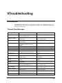
Troubleshooting
10-1
Introduction ............................................................................................................................................... 10-1
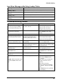
Transmit Error Messages ............................................................................................................ 10-1
Bar Code Data Errors .................................................................................................................. 10-2
Function Recall Errors ................................................................................................................ 10-2
Miscellaneous Errors................................................................................................................... 10-2
Allow Duplicates Error Messages............................................................................................... 10-3
Function Search Errors................................................................................................................ 10-4
Lookup/Data File Errors During FUNCTION TRANSMIT ....................................................... 10-4
Serial Input Error Messages ........................................................................................................ 10-4
Input Error Message while Using Lookup Tables....................................................................... 10-5
Troubleshooting Guide.............................................................................................................................. 10-5
Specifications
11-1
General Specifications............................................................................................................................... 11-1
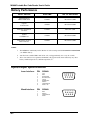
Battery Performance.................................................................................................................................. 11-2
Input/Output Specifications....................................................................................................................... 11-2
Maintenance
12-1
Introduction ............................................................................................................................................... 12-1
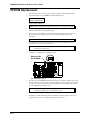
Battery Replacement ................................................................................................................................. 12-1
EPROM Replacement ............................................................................................................................... 12-2
Avoiding Damage...................................................................................................................................... 12-3
Electrical ..................................................................................................................................... 12-3
vii
M3000 Portable Bar Code Reader User's Guide
Mechanical .................................................................................................................................. 12-3
Cleaning ...................................................................................................................................... 12-3
Appendixes
A-1
APPENDIX A - BAR CODE FUNCTION & SPECIAL KEYS ............................................................... A-2
FUNCTION KEYS ...................................................................................................................... A-2
SPECIAL KEYS .......................................................................................................................... A-2
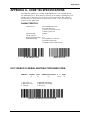
APPENDIX B - CODE 39 SPECIFICATIONS ......................................................................................... A-3
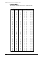
APPENDIX C - FULL ASCII EXTENSION TO CODE 39...................................................................... A-5
APPENDIX D - UPC SPECIFICATIONS................................................................................................. A-6
UPC VERSION E ........................................................................................................................ A-7
APPENDIX E - EAN SPECIFICATIONS................................................................................................. A-7
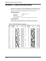
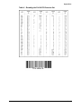
APPENDIX F - INTERLEAVED 2 of 5 SPECIFICATIONS ................................................................... A-8
APPENDIX G - CODABAR SPECIFICATIONS ................................................................................... A-10
APPENDIX H - CODE 128 SPECIFICATIONS..................................................................................... A-11
UCC-128 MOD 10 SERIAL SHIPPING CONTAINER CODE: .............................................. A-11
CHARACTER SET: .................................................................................................................. A-12
APPENDIX I - CODE 93 SPECIFICATIONS ........................................................................................ A-14
CHARACTERISTICS ............................................................................................................... A-14
CHARACTER SET ................................................................................................................... A-14
APPENDIX J - SOURCES OF BAR CODE STANDARDS................................................................... A-16
APPENDIX K - M3000 ASCII CHARACTER CHART........................................................................ A-18
APPENDIX L -NON-ASCII SPECIAL CHARACTER DEFINITIONS
FOR PC's AND PC TERMINALS........................................................................................................... A-19
NON-ASCII Delay Character Values * ..................................................................................... A-19
APPENDIX L - M3000 SPECIAL & FUNCTION KEYS FOR BAR CODES (Continued) .... A-20
APPENDIX M - M3000 SPECIAL CHARACTER DEFINITIONS FOREMBEDDED HEADER
INPUTS AND TRANSMIT PAUSE* ....................................................................................... A-20
Index............................................................................................................................................................. I-1
viii
Overview
Introduction
The Model 3000 Portable Bar Code Reader combines numerous features in a single, versatile unit.
The added productivity you get by using bar code technology can now be multiplied across a wide
array of applications. You can check current inventory in the stockroom, and track product sales
at the register. The unit can operate on a real-time network or multi-user system, and also transmit
transaction files by modem to your host computer. You do all this by configuring the M3000 in
one of the following modes:
•
•
Portable Mode
Non Portable Modes: Keyboard wedge, Serial wedge, and RS-232 Serial
In addition to these operating modes the M3000 features six built-in, ready-to-use programs, a
calculator function, and a real-time clock that displays date and time information. The M3000
features 64K of memory that is enhanced by data compression so that the apparent memory
available to the unit is 128K. The M3000 is fully programmable. The unit comes with a built-in
program generator that allows you to easily create custom programs. Simply enter the prompts
and data requirements and the M3000 creates the program for you. The programs you create can
be easily transferred to and from a personal computer.
Enhanced features include:
•
Lookup tables
•
Importing ASCII Lookup Files and Data files
•
RS-232 Serial Input
•
Transmit Pause
•
Header and File Name Output Options
•
Start & End of Transmit Text
•
Auto File Save Option
•
Programmable Bar Code Viewing Delay
•
Input Overwrite Option
You can scan virtually all industry standard bar code symbologies using wands, CCD scanners, 5volt laser scanners, and slot readers. You can also enter data directly from the keyboard and the
RS-232 Serial Port.
ix
M3000 Portable Bar Code Reader User's Guide
Portable Mode
The M3000 can go wherever you need to scan bar codes. Typically, this includes shop or
warehouse inventory and other asset management applications. In the portable mode the M3000
operates on a standard 8-volt Alkaline battery and can operate over 70 hours on a single battery.
A user selectable time-out feature saves battery life by shutting off the M3000 when the unit is not
in use. Just press ON to resume operation from where you were before the unit shut down. The
M3000 always saves the current operating status and contents of random access memory(RAM)
when power is turned off.
Non Portable Modes
The unit operates in three non portable modes; Keyboard Wedge, RS-232 Serial Wedge, and
RS232 Serial. In the wedge modes the M3000 sends bar code data directly to your PC or host
computer just as if you typed the information on the keyboard. When you combine the RS232
serial mode with SOFTCOM communications software (included with the M3000), the M3000
emulates a PC keyboard.
Communications
The M3000 can perform file transfers through a variety of interfaces:
•
Keyboard Wedge
•
RS-232 Serial Wedge for Serial ASCII Terminals
•
RS-232 Serial
•
Hayes Compatible Modem
The M3000 supports standard communication protocols such as XON/XOFF and XMODEM
(CRC16, Checksum), and can transmit serial data at speeds up to 38400 bps. The M3000 includes
four PC-based communications utilities:
•
PCOM
•
SOFTCOM - RS-232 keyboard emulation program
•
MONITOR - RS-232/keyboard communication diagnostic utility
•
M3000
- RS-232/Modem file transfer & programming program
PROGRAMMER
- RS-232/ Modem file transfer program
These programs provide the ability to use all the M3000 communication interfaces and to debug
your data output as well.
x
Overview
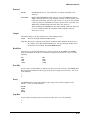
Style Conventions Used in This Manual
Every effort has been made to make the use of this manual as simple, and as intuitive as possible.
The following is a summary of style conventions that are used throughout the manual.
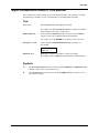
Text:
Normal Text
Standard body text used throughout the manual.
For example: The Model M3000 Portable Bar Code Reader combines
numerous features in a single, versatile unit.
Bold Normal Text
Used to indicate Actual Keys that the user presses on the M3000 to
complete a task, and to emphasize important information.
For example: Press the ENTER key to advance to the next record.
Monospace Text
Used to simulate actual M3000 LCD messages, prompts, etc.
For example:
Select Program
>Pgm P2
Bold Italic Text
References to chapters, appendixes or other text citations.
For example: Refer to Appendix A for information on Function Keys.
Symbols:
>
The Greater Than Cursor is used to indicate that the ENTER key or Up/Down Arrows
should be used to move to the next menu level.
➡
The Arrow Cursor is used to indicate that the Left/Right Arrows are used to select or
move between options.
xi
1Installation
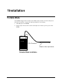
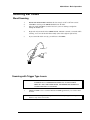
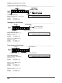
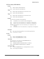
Portable Mode
Your M3000 is shipped with a standard 9-volt Alkaline battery installed. The unit is fully tested
and ready for operation. To prepare the unit for portable bar code scanning:
1.
Turn OFF power to the M3000.
2.
Plug the 9-pin connector from a wand or other input device into the 9-pin receptacle on the
M3000.
9-Pin Connector
Wand or other input device
Portable Mode Installation
1-1
M3000 Portable Bar Code Reader User's Guide
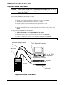
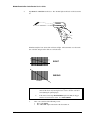
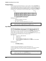
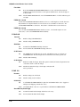
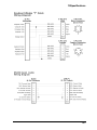
Keyboard Wedge Installation
Caution: TURN OFF POWER to the COMPUTER and M3000. Failure to remove
power while plugging and unplugging cables or the shunt, can permanently
damage the system.
To prepare the M3000 for Keyboard Wedge operation:
1.
TURN OFF POWER to the COMPUTER and to the M3000.
2.
Plug the 26-pin connector from the keyboard wedge Y-cable into the M3000.
3.
Unplug the keyboard connector from the back of the computer.
4.
Plug the keyboard connector into the keyboard receptacle of the Y-cable.
5.
Plug the remaining Y-cable connector into the keyboard port of the computer.
6.
Plug the 9-pin connector from a wand or other input device into the 9-pin receptacle on the
M3000.
To Temporarily use the M3000 in the Portable Mode:
1.
TURN OFF POWER to the COMPUTER and to the M3000.
2.
Unplug the 26-pin connector of the keyboard wedge Y-cable from the M3000.
3.
Connect the Shunt to the end of the connector you just unplugged from the M3000.
NOTE: The Shunt is the 26-pin male connector without an attached cable.
Keyboard Wedge Y-Cable
To PC Keyboard Connector
26-Pin
Connector
PC, XT, AT, PS-2,
or Compatible
Keyboard Din Connectors
Keyboard
9-Pin
Connector
Wand or other
input device
Keyboard Wedge Installation
1-2
1Installation
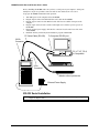
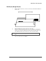
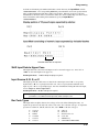
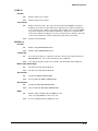
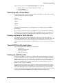
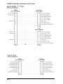
Serial Wedge Installation
The serial wedge connects between an RS-232 serial terminal and a host computer. Before
installing the serial wedge, make sure you have established communications between the terminal
and the host. Next, write down the existing communication parameters in use by the system. To
prepare the M3000 for serial wedge operation:
25-pin Connector from
the Serial Y-Cable
Terminal
Serial Cable to Host
Host Computer
25-Pin Connectors
Serial Wedge Y-Cable
26-Pin
Connector
Input device
Wand or other
9-Pin
Connector
External Power Supply
Serial Wedge Installation
1.
2.
3.
4.
5.
6.
7.
Turn OFF power to the terminal and to the M3000.
Unplug the serial cable from the terminal.
Plug the 26-pin connector from the serial wedge Y-cable into the M3000.
Plug the male 25-pin connector of the serial Y-cable into the connector labeled "Modem"
or "Main" on the back of the terminal.
Plug the female 25-pin connector from the serial Y-cable into the cable going to the host
computer (the cable you unplugged from the terminal.)
Plug the 9-pin connector from a wand or other input device into the 9-pin receptacle on
the M3000.
Plug the external power supply cable into the connector located on the lower left corner
of the M3000.
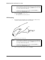
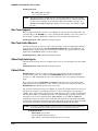
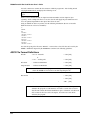
RS-232 Serial Installation
1-3
M3000 Portable Bar Code Reader User's Guide
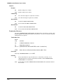
Prior to installing the M3000, make sure you have a serial port on your computer. Serial ports
usually have 25-pin or 9-pin male connectors and are often labeled Com 1 or Com 2.
To prepare the M3000 for RS-232 Serial operation:
1.
2.
3.
4.
5.
6.
Turn OFF power to the computer and to the M3000.
Plug the 26-pin connector from the RS-232 serial cable into the M3000.
Plug the 25-pin connector of the RS-232 serial cable into an available Com port on the
computer.
Plug the 9-pin connector from a wand or other input device into the 9-pin receptacle on
the M3000.
Plug the external power supply cable into the connector located on the lower left corner
of the M3000.
Install the memory resident keyboard emulation program, SOFTCOM.
PC Serial Cable (RS-232)
To Computer RS-232 port
26-Pin
Connector
PC, XT, AT, PS-2,
or Compatible
9-Pin
Connector
Wand or other input device
External Power Supply
RS-232 Serial Installation
NOTE: If your computer uses a 9-pin connector for the Com port, you need a 25-pin to 9-pin
adapter or adapter cable.
1-4
1Installation
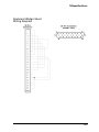
Modem Installation
The M3000 works with any Hayes compatible modem. To prepare the M3000 for modem
operation:
1.
Turn OFF power to the modem and to the M3000.
2.
Plug the 26-pin connector from the Modem Cable into the M3000.
3.
Plug the 25-pin connector from the Modem Cable into the modem connector.
4.
Plug the 9-pin connector from a wand or other input device into the 9-pin receptacle on the
M3000.
25-Pin Connector
Modem Cable
26-Pin
Connector
Modem
Modem Installation
Installing Input Devices
The M3000 accepts the following input devices:
•
Bar Code Input Devices
- Wands
- 5 Volt Laser Scanners
- Slot Reader (Badge Readers)
•
Serial Input Devices (Portable Mode Only)
To install a bar code input device, plug the male 9-pin connector of the scanner into the 9-pin
female connector of the M3000.
To install the Serial Input Device, use the RS-232 serial cable provided.
1-5
2Keyboard
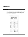
Introduction
The M3000 keyboard has been designed with separate alpha and numeric keys and a color code of
red, white, and blue for multiple keystroke combinations. The SHIFT key can be pressed with any
of the keys with blue headers to change the key operation to the character in blue. The FUNC key
can be pressed with any of the keys with red headers to perform all the M3000 functions. All
alpha keys can be changed to upper case by pressing the CAPS key. The following is a
description of all the keys on the M3000 keyboard.
2-1
M3000 Portable Bar Code Reader User's Guide
Keyboard Layout
æ
moves the cursor up through any M3000 menu or input field. The æ key is used to
view menu selections when the > prompt is displayed.
moves the cursor down through any M3000 menu or input field. The
view menu selections when the > prompt is displayed.
moves the cursor left through any M3000 menu or input field. The
view menu selections when the prompt is displayed.
moves the cursor right through any M3000 menu or input field. The
view menu selections when the prompt is displayed.
key is used to
key is used to
key is used to
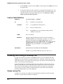
CALC
function allows you to make calculations while collecting data or programming the
M3000. See the Function Reference Chapter for detailed instructions on the operation
of the CALC keys.
CAPS
toggles between upper and lower case input of alphabetical characters.
CLEAR
function clears an entire input field.
DEL
deletes any character at the cursor position. If the cursor follows a string of characters,
the DEL key will delete the character to the left of the cursor position.
ENTER
accepts information in an input field and advances the cursor to the next input field.
ENTER also selects menu items in any of the M3000 menus.
ERASE
function erases a record or an entire file while in INPUT or PROGRAM mode.
ERASE also can be used from the main M3000 menu to erase data and lookup files .
EXIT
exits any operation being performed.
FUNC
is used with any of the M3000 keys with Red headers. This key allows you to select
any of the M3000 portable functions by pressing FUNC and the function to be selected.
The options are:
CALC
CLEAR
ERASE
HELP
INPUT
INSREC
PROG
RECALL
SEARCH
SETUP
STATUS
STORE
TIME
XMIT
HELP
function displays the field settings such as length, types of bar codes allowed or type of
characters allowed for the current input field.
INPUT
function is for data collection. The M3000 will prompt the operator for program
selection and then allow data entry into a new or existing data file. See the Quick Start
- Basic Operations Chapter for more information on collecting data.
INS
allows you to INSERT data at the cursor position, moving all existing data to the right.
The INSERT mode is indicated by a fast flashing cursor.
INSREC function inserts an empty record before the current record while in either the INPUT or
PROGRAM mode.
2-2
NO
enters an N for NO at any YES/NO prompt. The NO key will also enter an N in any
input field allowing alphanumeric data.
OFF
turns the M3000 unit OFF. When the unit is used as a keyboard wedge, the unit turns
itself ON and OFF with the computer.
2Keyboard
PROG
PROGRAM function allows the operator to custom write a new program or change
any existing program. See the Programming Chapter for further details on how to
program the M3000.
RECALL function will insert any input field (string of characters) that has been stored with the
STORE function after clearing the present input field. See the Function Reference
Chapter for more information about the RECALL function.
SEARCH function is used to search and find an input field that matches search text (string of
characters) while in the data collection INPUT mode. SEARCH can be called only
from a data collection input field. See the Function Reference Chapter for more
information about the SEARCH function.
SETUP
function is a series of menus to custom set the M3000 for portable options, in-line
reader options, and transmit options.
SHIFT
toggles the keys with Blue headers to the character on the blue background except
during non portable mode operation and at the Portable Mode Select
Function display. The SHIFT key toggles between the current non portable mode
and the Portable Mode Select Function display when viewing the main
menu. When using the option, Setup, Other Setup, Wedge Kypad (Wedge Keypad),
press the Exit key on the M3000 to return to the Portable Mode Select
Function display.
SPACE
is used to enter the space character.
STATUS function displays information specific to data or program files being viewed and also
information about the M3000 such as memory available and CAPS status. See the
Function Reference Chapter for a complete list of status information.
STORE
function stores the current input field data (string of characters) to be used with the
RECALL function. See the Function Reference Chapter for more information about
the STORE function.
TIME
function displays the M3000 setting for the Day Of Week, Month, Day, Year, Hour,
Minute, Second, and AM or PM.
XMIT
function is used to transmit files to and from the M3000. See the Communications
Chapter for more information on transmitting data.
YES
enters a Y for YES at any YES/NO prompt. The YES key will also enter a Y in any
input field allowing alphanumeric data.
Other Key Combinations
FUNC +
moves the cursor to the first input of the last record of a data or program file.
FUNC + æ moves the cursor to the first input of a data or program file.
FUNC +
moves the cursor to the first input in the next record of a data or program file.
FUNC +
moves the cursor to the first input in the previous record of a data or
program file
2-3
3Function Reference
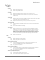
Introduction
The M3000 has several functions that simplify programming and data collection. These functions
and their operations are described in this chapter. To select a function, press and release the
FUNC key, and then press the desired function.
Arrow Keys
With the Function Key
The arrow keys can be used with the FUNC key to move the cursor to different location in a data
or program file. Below are the actions of each arrow key when used with the FUNC key:
Down Arrow
moves the cursor to the first input of the last record of a data or
program file.
Up Arrow
moves the cursor to the first input of a data or program file.
Right Arrow
moves the cursor to the first input in the next record of a data or
program file.
Left Arrow
moves the cursor to the first input in the previous record of a data or
program file
Calculator
The CALC function accesses a 4-Function Calculator and can be used while collecting data or
programming the M3000. The keys used for calculations are:
+
*
/
=
Addition
Subtraction
Multiplication
Division
Total
To use the calculator, press FUNC, then CALC. The M3000 prompts:
Calculator
0
Enter the numbers you want to calculate using the math symbols. Once the = key is pressed and a
total is displayed, you only need to enter a another number to start a new calculation or enter +, -,
*, or / to continue the calculation.
3-1
M3000 Portable Bar Code Reader User's Guide
To add 377 plus 795 minus 234, enter "377+795-234=".
EXAMPLE:
To multiply 17 times 24, enter "17*24=".
To divide 547 by 12, enter "547/12=".
To add 24 plus 95, then multiply by 17, enter "24+95*17=".
NOTE: You do not have to press the SHIFT key to use the calculator keys; the + - * / and +
will automatically be available. You may input up to 8 characters to the left of the
decimal and 6 characters to right of the decimal. To clear the calculator data input
press FUNC, then CLEAR or press the DEL key to erase one character at a time. The
ENTER key and Down Arrow key will also total a calculation.
To exit the calculator function, simply press the EXIT key.
CLEAR
The CLEAR function can be used while in data collection or programming mode to clear an entire
input field. Press FUNC, then CLEAR when you are in the input field you want to clear. If an
input field has been specified as INPUT REQUIRED, you must re-enter information in this field.
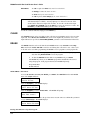
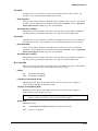
ERASE
The ERASE function can be used from the main M3000 menu to erase Data Files or Lookup
Files stored in the M3000. ERASE can also be used during data collection to erase a data record
or file and can be used while programming the M3000 to erase a program record or program file.
NOTES:
1.
You can only Erase a program by using FUNC PROG, selecting the program to
edit, then using FUNC ERASE to erase the program.
2.
To abort the ERASE function while in any M3000 mode, press EXIT.
The M3000 only allows you to ERASE a program that has NO data files stored
using that program. If the program has data, the M3000 will prompt:
Program Has Data
No Edit Allowed
MAIN MENU - DATA FILES
To erase all data files stored in your M3000, press FUNC, then ERASE from the main M3000
menu. The M3000 will show:
Erase Selection
>Data Files
Press the ENTER key. The M3000 displays:
Erase Selection
>All Data Files
Press the ENTER key to erase All Data Files. The M3000 will prompt:
Erase All Data
Are You Sure?
Press N or NO to abort and return to the previous menu. Press Y or Yes to confirm that you intend
to erase All Data Files. The M3000 displays:
All Data Files
Have Been Erased
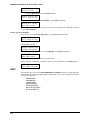
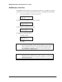
Erasing Data Files For a Specific Program
3-2
3Function Reference
If you choose to erase data files for a specific program, you may erase All Data Files for that
program or use the UP and Down Arrow keys to select individual data files for that program.
Press the Down Arrow from the
Erase Selection
>All Data Files
display.
The M3000 will prompt:
Erase Selection
>Pgm prgname
Press the ENTER key to erase Data Files for the displayed program. The M3000 will prompt:
Erase prgname
>All Data Files
Press N or NO to abort and return to the previous menu.
Press Y or Yes to erase All Data Files for the selected program. The M3000 will prompt:
Erase All Data
Are You Sure?
Press the Y or Yes a second time confirm that you intend to erase All Data Files for the selected
program.
The M3000 displays:
All Data Erased
For Pgm filname
Erasing Specific Data Files For a Program
To erase a Specific Data File for the selected program, press the Down Arrow from the
Erase prgname
>All Data Files
display.
Use the Up and Down Arrow keys to select a specific data file. Press ENTER when you have
selected the data file to be erased. The M3000 prompts:
Erase prgname
>File filename
To erase the displayed file, press ENTER. The M3000 prompts:
Erase filename
Are You Sure?
Press N or NO to abort and return to the previous menu.
Press Y or Yes to confirm that you intend to erase the selected data file.
The M3000 prompts:
File filename
Has Been Erased
MAIN MENU - LOOKUP FILES
To erase ALL lookup files stored in your M3000 or Individual Lookup Files, press FUNC,
then ERASE from the main M3000 menu. The M3000 will show:
3-3
M3000 Portable Bar Code Reader User's Guide
Erase Selection
>Data Files
Press the Down Arrow and the M3000 will show:
Erase Selection
>All LkUp Files
Press the ENTER key to erase All Lookup Files. The M3000 will prompt:
Erase All LkUp
Are You Sure?
Press N or NO to abort and return to the previous menu. Press Y or Yes to confirm that you intend
to erase All Lookup Files.
Erasing Specific Lookup Files
If you choose to erase Specific Lookup Files, press the Down Arrow from the
Erase Selection
>All LkUp Files
display.
The M3000 will prompt:
Erase Selection
>LkUp filename
Press the ENTER key to erase the selected Lookup File. The M3000 will prompt:
Erase filename
Are You Sure?
Press N or NO to abort and return to the previous menu.
Press Y or Yes to confirm that you intend to erase the selected lookup file. The M3000 prompts:
File filename
Has Been Erased
HELP
This function can be used in the M3000 PROGRAM and INPUT functions to view the input field
requirements. The following prompts and their requirements can be viewed for any input using the
arrow up and down keys.
Minimum Size
Maximum Size
Input Required
Input Mask Type
Serial Input Status
Bar Code Type Status
Bar Codes Allowed
3-4
3Function Reference
INSREC
This function is used to insert records in INPUT or PROGRAM mode. While collecting data,
press FUNC, then INSREC to insert an empty data record before the one being viewed. While
creating or editing an M3000 program, press FUNC, then INSREC to insert an empty program
record before the one being viewed.
RECALL
This function will insert any input field (string of characters) that has been stored with the M3000
STORE function. Press FUNC, then RECALL. This string of characters will be inserted in place
of any existing data in the current input field.
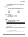
SEARCH
This function allows the operator to search for an input field with a string of characters that match
the SEARCH text. The SEARCH function can be used only in the M3000 INPUT function, data
collection mode. Press FUNC, then SEARCH. The M3000 will prompt:
Search Text
and request the operator to type or scan a string of characters to search. Search can be executed in
the following three ways:
•
ARROW UP
•
ARROW DOWN will search for any input field following the one being viewed that
matches the SEARCH string.
•
ENTER
will search for any input field previous to the one being viewed that
matches the SEARCH string.
will search the entire file for any input field that matches the
SEARCH string.
The M3000 will confirm only MATCH FOUND if the search text exactly matches an entire data
input field. The M3000 will prompt NO MATCH FOUND if no data input fields exactly match
the search string of characters.
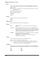
STATUS
This function is useful in both the INPUT and PROGRAM modes. It displays the following
information: The following status information can be viewed using the arrow up and down keys.
•
•
•
•
•
•
•
•
•
•
•
•
•
•
Number of bytes (memory) available for data or programs
Percentage of memory available for data or programs
Data or program record number being viewed and the total
number of records input in the data file or program file
Name of the current running program
Name of the current data file being edited
Number of program files stored in the M3000
Number of lookup files stored in the M3000
Number of data files stored in the M3000
Number of lookup files stored in the M3000
M3000 CAPS mode status
Battery power status
Recall buffer data
The M3000 firmware version number
Rom Checksum
3-5
M3000 Portable Bar Code Reader User's Guide
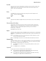
STORE
This option stores the current input field (string of characters) to be used with the RECALL
function. Press FUNC, then STORE. The information is stored in memory and can be recalled
using function recall (FUNC RECALL).
TIME
This function displays the M3000 setting for the day of week, month, day, year, hour, minute,
second, and AM or PM.
3-6
4Quick Start - Basic Operations
The only thing you need to scan your first bar code is the M3000, a scanning device, and a bar
code. For this quick start we'll begin by describing operation using a wand. Other types of
scanning devices include: laser scanners, CCD scanners, and slot readers. We'll talk about the use
of other scanners later. Let's assume that you have the M3000 with an installed wand.
We'll begin by operating the unit in the portable mode, load, and run one of the built-in programs.
After that we'll scan some bar codes, enter some data manually, and use the calculator function to
extend some quantities. Calculations made with the calculator can be easily stored and retrieved
back into your data files as you work.
Startup - Portable Mode
1.
Press ON to turn on the M3000.
If you have a new unit, the display should show the current date and time. You will do
much of your data collection in the portable mode. Press EXIT. The display shows:
Portable Mode
Select Function
2.
If your M3000 displays any other message, press EXIT until the display shows:
Portable Mode
Select Function
Loading a Built-in Program into RAM
Before you collect data in the input mode, you have to load a program from within the program
mode. When the M3000 is shipped, all 6 built-in programs are in Read Only Memory (ROM). To
use a program you must first load that program into Random Access Memory (RAM). Programs
that you use are much like a fill-in-the-blank questionnaire. The program shows you a prompt on
the display, and you respond by either scanning a bar code, or by entering the data manually on the
keypad.
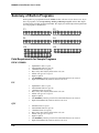
Built-in program P2 is used frequently by M3000 users for inventory data collection. It has a part
number field that is displayed as P/N, and, it has a quantity field that is displayed as Qty. To load a
built-in program into RAM:
4-1
M3000 Portable Bar Code Reader User's Guide
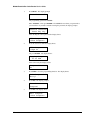
1.
Press PROG. The display prompts:
Enter Password
The programming password is M3000P.
Enter "M3000P". Then press ENTER. The M3000 does not show you passwords as
you enter them. If you make a mistake entering the password, the display prompts:
INVALID PASSWORD
Press Any Key
After entering the correct password the display shows:
Edit Program
>*New Program*
2.
Press the down arrow until the display shows:
Edit Program
>*Pgm P2
and press ENTER. The display shows:
Copying Program
P2 To RAM
After a brief delay the display shows:
Program Name
P2
3.
Press EXIT to leave the programming function. The display shows:
Exit Program
Entry?
4.
Press YES. The display prompts:
Save New
Program?
5.
Press YES. The display shows:
Edit Program
>*New Program*
4-2
4Quick Start - Basic Operations
6.
Press EXIT. The display shows:
Portable Mode
Select Function
Now that program P2 has been copied to RAM, it can be used to prompt you for data input.
Using the INPUT Function
Before you start inputting data you need to:
•
•
•
Select the INPUT function
Select a program
Create a new data file, or load an existing data file
Your display shows:
Portable Mode
Select Function
If that is not the message on your display, press EXIT until it is.
Selecting a Program
To select program P2 for inputting data:
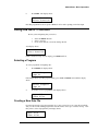
1.
Press INPUT, the display shows:
Select Program
>Pgm P2
If the display shows any other program listing, press an UP or DOWN arrow until the display
shows:
Select Program
>Pgm P2
2.
Press Enter to select program P2. The display shows:
Input File
>*New File*
Creating a New Data File
If you haven't already selected program P2, do so. Now you need to create a data file to hold the
data you collect while running program P2. Data file names can be up to 8 characters long. Now
that you have selected program P2 your display shows:
Input File
>*New File*
4-3
M3000 Portable Bar Code Reader User's Guide
To create a new data file:
1.
Press Enter. The display shows:
Enter File Name
_
At this point you can enter any data file name you like.
2.
Since this is a practice session, type: INV1
and press ENTER. The display shows:
P/N _
QTY
Entering the file name has placed you within program P2, and P2 is now prompting you for input
data.
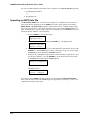
Entering Data into a Data File
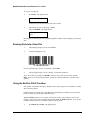
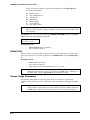
1.
The P/N input prompts you for a Part Number.
2.
Scan the following bar code.
0123456789
If you scanned the label correctly, you will hear a short BEEP.
3.
The Qty input prompts you for a quantity. To input the quantity 6:
Type "6" on the key pad and press ENTER. You have just recorded one record in data file
INV1. Next, let's scan another part number, and use the calculator function to calculate a large
quantity.
Using the Built-in CALC Function
Scan another value into the P/N input. With the cursor at the Qty input we can simulate a realistic
data collection problem.
For this problem, let's assume that a warehouse bin containing the part number you just scanned
holds 11 cartons of 12 items, plus 7 individual items.
With the M3000 you don't need a separate calculator or resort to pencil and paper to solve the
problem. You can access the calculator function from within the INPUT function. To access the
calculator function and enter calculation results into the Qty field:
1.
4-4
Press FUNC then CALC. The display shows:
4Quick Start - Basic Operations
Calculator
0
You need to enter the elements of the problem.
2.
Enter 11 * 12 + 7 =. The display shows:
Calculator
139
Next, you must store the result of the calculation.
3.
Press FUNC, then STORE.
4.
Press EXIT to return to the INPUT function. The display still shows the value of the last
part number you scanned and is prompting you for an entry in the Qty input. To retrieve
the results just calculated:
5.
Press FUNC, then RECALL. The RECALL function enters the calculation result in the
Qty input.
6.
Press ENTER to advance to the next record.
After collecting data you need to exit the INPUT function and save the contents of the data file.
Exiting and Saving a Data File
You can exit a data file, save the file, and resume data collection later on. To exit the data file:
1.
Press EXIT. The display shows:
Exit Data Entry?
2.
Press YES. The display prompts:
Save Data File?
3.
Press YES. The M3000 returns to the
Select Program
>Pgm P2
display.
The M3000 asked if you wanted to save the data file because this was the first time you had used
data file INV1. After you save a data file the first time, the M3000 automatically saves the
contents of the file when you press EXIT, and respond by pressing YES.
If other programs are in RAM you can use the Up and Down arrows to scroll through the available
programs.
4-5
M3000 Portable Bar Code Reader User's Guide
Edit/Review a Data File
The M3000 always links data files to the program that created them. To Edit/Review data files
you must first select the program that the data file is linked to. To Edit/Review data file INV1:
1.
Press the Up or Down arrow until the display shows:
Select Program
>Pgm P2
Press Enter to select Program P2. The display now shows:
Input File
>*New File*
Press the Down arrow until the display shows:
Input File
>File INV1
Press Enter to select Input file INV1.
3.
The display prompts:
Append To
End of File?
Press YES.
CAUTION: If you do not select Append the M3000 starts inputting data at the top of
the file and overwrites the contents of the data file that were entered earlier.
Unless you intend to overwrite or review previously entered data, always
select Append. If you intend to overwrite or review previously entered
data, press NO at the Append prompt.
NOTE:
4-6
If you do not select Append, you can still use the arrow keys to scroll
through data file records and view or edit as required. To resume data
collection, use the arrow keys to scroll to the end of file. Next, scan or enter
data as described earlier.
4Quick Start - Basic Operations
4.
Continue to scan bar codes and enter values for the P/N and Qty fields, as described in
Inputting Data into a Data File. When you are ready to stop collecting data:
5.
Press EXIT. The display shows:
Exit Data Entry?
_
6.
Press YES. The M3000 returns to the
Select Program
>Pgm P2
display. The contents of the data file were automatically saved when you
pressed YES.
7.
Press EXIT again to return to the Portable Mode Select Function
Input.
Automatic Input
The M3000 provides an automatic input feature. When Automatic Input is enabled all you need to
do to input data from the portable mode is press INPUT.
NOTE: Automatic Input uses the first program found in RAM. If no data file exists for
the active program, the M3000 creates a file named- FILE #1. If a data file, or
multiple data files exist for the active program, the M3000 uses the first file
created for that program.
The Automatic Input feature is enabled by a SETUP option and works when the following
conditions exist:
•
•
At least one program is loaded into RAM.
The SETUP Function option, Automatic Input is ON
Startup - Non Portable Mode
The M3000 supports three non portable modes; Keyboard Wedge, Serial Wedge, and RS-232.
Before you can use the M3000 in one of the non portable modes, first install the mode you intend
to use. See the Installation Chapter for the proper installation procedure.
During all non portable operations, the automatic time-out feature is disabled. When used in the
Keyboard Wedge mode, the M3000 receives power through the keyboard interface. If you intend
to operate for extended periods of time in the Serial Wedge or the RS-232 modes, use an external
power supply to conserve battery life.
During all wedge mode operations, the M3000 sends scanned data to the computer or host just as
if the information had been typed at the keyboard.
4-7
M3000 Portable Bar Code Reader User's Guide
Keyboard Wedge Mode
After installation, the M3000 is powered ON, and ready to accept scanned bar codes. To input
data into the computer:
Scan a bar code label. The M3000 beeps to signal a good read. Data from the input device is sent
to the computer just as if the data had been typed at the keyboard.
NOTE: During Keyboard Wedge operation, only data from a scanning device is sent to
the computer. The M3000 does not send out data entered on the keypad by
default, but can be enabled by using the Wedge Kypad option in setup.
Serial Wedge Mode
To operate the M3000 in the Serial Wedge Mode perform the following:
1.
Press ON. The display shows:
Portable Mode
Select Function
2.
Press SHIFT. The M3000 shows the current non portable mode. If the display does not
show:
Serial Wedge
you need to change the non portable mode setup. To change the non portable mode to
Serial Wedge, do the following:
a)
Press FUNC, then SETUP. The display shows:
Setup Selection
>Date/Time
b)
Press the Down arrow once. The display shows:
Setup Selection
>Nonport. Mode
c)
Press Enter to select the non portable mode setup option.
d)
Press the LEFT or RIGHT arrow key until the display shows:
Nonportable Mode
➨SERIAL WEDGE
4-8
4Quick Start - Basic Operations
e)
Press EXIT twice. The display shows:
Serial Wedge
The M3000 is setup for Serial Wedge operation and ready to send bar code data
to your computer.
3.
Scan a bar code label. The M3000 beeps to signal a good read. Data from the input
device is sent to the computer just as if the data had been typed at the terminal.
NOTE: During Serial Wedge operation, only data from a scanning device is
sent to the computer. The M3000 does not send out data entered on
the keypad by default, but can be enable by using the Wedge Kypad
option in setup.
RS-232 Serial Mode
When the M3000 operates in the RS-232 mode, bar code data is transmitted serially to the host
computer. If your computer software does not require keyboard emulation your M3000 is ready
for operation. If your system requires keyboard emulation, you should install the SOFTCOM
program that was shipped with the M3000.
Refer to Communications, for installation instructions. SOFTCOM requires an MS-DOS, PCDOS or other DOS compatible operating system, version 2.1 or higher.
To operate the M3000 in the RS-232 Serial Mode perform the following:
1.
Press ON. The display shows:
Portable Mode
Select Function
2.
Press SHIFT. The M3000 displays the current non portable mode. If the display does
not show:
RS232 Serial
you have to change the non portable mode setup. To change the non portable mode to
RS-232 Serial, do the following:
a)
Press FUNCTION, then SETUP. The display shows:
Setup Selection
>Date/Time
b)
Press the Down arrow once. The display shows:
Setup Selection
>Nonport. Mode
c)
Press Enter to select the non portable mode setup option.
4-9
M3000 Portable Bar Code Reader User's Guide
d)
Press the LEFT or RIGHT arrow key until the display shows:
Nonportable Mode
➨RS232 SERIAL
e)
Press EXIT twice. The display shows:
RS232 Serial
The M3000 is setup for RS-232 Serial operation and ready to send bar code data
to the host computer.
3.
Scan a bar code label. The M3000 beeps to signal a good read. Data from the input
device is sent to the host computer.
NOTE: During RS232 Serial operation, only data from a scanning device is
sent to the computer. The M3000 does not send out data entered on
the keypad by default, but can be enabled by using the Wedge Kypad
option in setup.
4-10
4Quick Start - Basic Operations
Scanning Bar Codes
Wand Scanning
1.
2.
3.
HOLD THE WAND LIKE A PENCIL, tilted at an angle of 10º to 30º from vertical.
TOUCH the wand tip to the WHITE SPACE before the label.
Move the wand QUICKLY across the label as if you were drawing a straight line
through the middle of it.
4.
Begin and end your stroke in the WHITE SPACE. Maintain a smooth, even stroke while
scanning. You can read labels bi-directionally (either left-to-right or right-to-left).
5.
If you scanned the label correctly, you will hear a short BEEP.
Scanning with Trigger Type Lasers
CAUTION:
1.
ALTHOUGH THE LIGHT EMITTED FROM CLASS II AND CLASS IIA
LASERS IS NOT CONSIDERED HAZARDOUS, AVOID STARING
DIRECTLY INTO THE LIGHT BEAM. EXTENDED EXPOSURE MAY
CAUSE DAMAGE TO YOUR EYES.
AIM the LASER at a bar code label. Hold the LASER approximately 3 to 6 inches from
the label.
NOTE: The maximum scanning distance depends on the label density. Typical scanning
distances vary from 3 to 18 inches.
4-11
M3000 Portable Bar Code Reader User's Guide
2.
SQUEEZE the TRIGGER on the laser. The "SCAN" light on the back of the laser turns
on.
Simultaneously the laser emits a thin red beam of light. The beam must cover the entire
bar code label and part of the white area on both sides.
RIGHT
123456
WRONG
123456
NOTES: 1.
2.
3.
4-12
If the laser has not read the label within approximately one second, it
turns off the beam. Try moving the laser closer to the bar code label
and adjusting the pointing angle.
If the Laser/CCD setup ALWAYS RUN option is OFF, the trigger
must be released between scans. See FUNC SETUP.
After a successful read the following occurs:
• The reader BEEPS.
• The "DECODE" light on the back of the laser turns on.
4Quick Start - Basic Operations
Scanning with the MS941 Triggerless Laser
The MS941 is a triggerless laser activated by a bar code or reflective object passing through its
beam. It can be set in its cradle for "hands-free" operation, or held in the hand.
See the following steps for scanning instructions:
1.
Point the LASER at a bar code label or, for hands-free scanning, bring the bar code to the
laser beam. The distance from the MS941 laser to the bar code should be approximately
1 to 5 inches.
CAUTION: ALTHOUGH THE LIGHT EMITTED FROM CLASS II LASERS IS NOT
CONSIDERED HAZARDOUS, AVOID STARING DIRECTLY INTO THE
LIGHT BEAM. EXTENDED EXPOSURE MAY CAUSE DAMAGE TO YOUR
EYES.
2.
The laser begins scanning as soon as the bar code is brought within 5 inches of the front
of the laser. The red light on the back of the LASER's handle stays on as long as it is
attempting a read. The laser beam must cover the entire bar code label and part of the
blank area on both sides. Examples of bar code scans are shown below:
RIGHT
123456
WRONG
123456
4-13
M3000 Portable Bar Code Reader User's Guide
NOTES: 1.
2.
3.
If a read does not occur immediately, try moving the laser closer to the bar code
label and adjusting the pointing angle. If the reader has not read the label within
the time period specified in the Laser/CCD Setup TIMEOUT option (the default
is 1 second), it will turn off the light beam.
For triggerless operation, refer to "Laser/CCD Setup ALWAYS RUN and
Laser/CCD Setup TRIGGER OFF" options.
After a successful read the following occurs:
• The decoder BEEPS.
• The red light on the back of the laser turns off.
CCD Scanning
1.
Place the CCD scanner on the label or close to it (within one inch). Make sure the bar
code label fits completely within the frame of the CCD opening.
2.
PRESS the button on the CCD scanner.
NOTES: 1.
2.
3.
4-14
If a read does not occur immediately, try moving the CCD closer to the bar code
label and adjusting the pointing angle. If the reader has not read the label within
the time period specified in the Laser/CCD Setup TIMEOUT option (the default
is 1 second), it will turn off the light beam.
For triggerless operation, refer to "Laser/CCD Setup ALWAYS RUN and
Laser/CCD Setup TRIGGER OFF" options.
After a successful read the following occurs the reader BEEPS.
4Quick Start - Basic Operations
Slot Reader (Badge Reader)
1.
Hold the CARD so that the bar code label is on the bottom and FACES the ARROW on
the slot reader.
2.
3.
Insert the CARD into the opening on either side of the reader.
Holding the CARD flat against the bottom of the reader, SLIDE the card through the
opening. You can slide the CARD bi-directionally (either left-to-right or right-to-left).
The CARD must maintain contact with the base of the reader while scanning.
NOTE: The center of the bar code must be positioned 0.5" from the bottom edge of the
card.
4.
After a successful read the reader BEEPS.
4-15
5Programming
Introduction to Programming
The M3000 Program Generator allows you to create and edit programs that prompt the operator
for input during data collection.
While you are learning the M3000 programming options, don't worry about selecting a wrong
input. You can always edit or delete a program if it is not exactly what you want. The M3000 has
been designed so that you cannot make a fatal programming error.
The Programming Form and Sample Program located after the Appendix will assist you in the
design and planning of new programs, and in the editing of built-in programs. Proper planning is
the key to trouble-free program design. Once you learn more about the programming options, you
will want to edit program files to meet your specific needs.
You cannot edit certain inputs of a program if the program has existing data files. The M3000
prevents the modification of the following options if the program has one or more data files:
Program Name
Header Input
Input Type
Stamp Commands
Input Maximum Size
Input Minimum Size
Input Required
Input Mask
The following information explains how to select a program, exit a program, select inputs for the
start of a program, and define inputs for each program record. A programming tutorial follows the
detailed explanations of program parameters.
Selecting Existing Programs
The M3000 is shipped with 6 built-in programs in Read Only Memory (ROM). To use a program
you must first load that program into Random Access Memory (RAM). Built-in program P2 is
used frequently by M3000 users for inventory data collection. It has a part number input that is
displayed as P/N, and, it has a quantity input that is displayed as Qty. To load a built-in program
into RAM:
Press PROG. The display prompts:
Enter Password
The programming password is M3000P.
1.
Enter "M3000P". Then press ENTER. This is a fixed password and cannot be changed.
The M3000 does not show you passwords as you enter them. If you make a mistake
entering the password, the display prompts:
INVALID PASSWORD
Press Any Key
After entering the correct password the display shows:
5-1
M3000 Bar Code Reader User's Guide
Edit Program
>*New Program*
2.
Press the down arrow to view a list of available programs. As you continue to press the
down arrow, program names appear on the display.
NOTE: Program names appear in the order of creation, or the order in which they were copied
from ROM into RAM. The names of built-in programs in ROM are preceded by an *
(asterisk). When you copy a program into RAM, the asterisk is removed from the
program name. If you have already loaded P2 from the Quick Start Chapter, select the
RAM copy of P2 which is not preceded by an *.
To select built-in program P2, press an up or down arrow until the display shows:
Edit Program
>*Pgm P2
and press ENTER. The display shows:
Copying Program
P2 To RAM
After the program has been copied to RAM, the display shows:
Program Name
P2
At this point you can begin editing the program.
Erasing a Program
To erase a program press FUNCT + ERASE while the program name is shown on the
display. For example, after you load program P2 the display shows:
Program Name
P2
To erase program P2 press FUNCT then ERASE. The M3000 prompts:
Erase File?
Press YES and the M3000 prompts:
Erase P2
Are You Sure?
Press YES again to confirm that you want to erase program P2. The M3000 displays:
File P2
Has Been Erased
Exiting a Program
To return to the Portable Mode Select Function display:
1.
5-2
Press EXIT to leave the programming function. The display shows:
5Programming
Exit Program
Entry?
2.
Press YES. The M3000 will verify the program you have created and display an error
message if any of the following have occurred:
• no inputs have been defined for the program
• no operator inputs have been defined for the program
• a loop has been created with no operator input.
3.
If you have just created a new program, the M3000 display prompts:
Save New
Program?
4.
Press YES. The display shows:
Edit Program
>*New Program*
5.
Press EXIT. The display shows:
Portable Mode
Select Function
Programming Tutorial
The information that follows explains the step-by-step procedures used to develop a practical
inventory program. This sample program uses many of the powerful, and some of the less obvious
features, that are built into the M3000, and is designed to be used with DOS on a PC. When a data
file created by this program is transmitted in the Keyboard Wedge Mode, or the RS232 Serial
Mode using SOFTCOM keyboard emulation software, the Start of File Text outputs a DOS C:
prompt and carriage return. The DOS Copy Con command creates a file named "datafile.dat". A
final carriage return follows the file name.
To ensure that SOFTCOM properly translates control codes from this program, make sure the
following settings have been made to the SOFTCOM using the SCONFIG.EXE Program:
Function Keys: Use Both
Special Keys: Use Both
Other SOFTCOM settings must match the settings of your M3000's Transmit Setup.
While using this tutorial, we recommend you refer to Sample Program Chart following the
Appendix. This chart outlines and summarizes the program you are about to create, and will help
you follow your progress through the creation of the program.
The name of this program is "EXAMPLE". "EXAMPLE" consists of 5 input definition sequences.
Of these five input definition sequences one is a Header, the remaining four are Record Inputs that
combine to create a loop.
Header:
User ID
Record Inputs: Item #
Qty
LOC
MM/DD/YY HH:MM
Date /Time Stamp (automatic input that the
operator does not see)
5-3
M3000 Bar Code Reader User's Guide
Creating/Naming the Program File
Enter Password
1.
Press PROG or (FUNC + PROG when at any display other than the Portable Mode
Select Function display) to enter the programming mode.
Enter "M3000P" and then press the ENTER key. The M3000 does not display
passwords as you enter them. This is a fixed password and cannot be changed.
After entering the correct password the display shows:
Edit Program
>*New Program*
2.
Press the ENTER key to create a new program file. The display shows:
Program Name
3.
Enter the name of the new program, "EXAMPLE", and press the ENTER key.
SOF (Start of File) Parameters
SOF Text
SOF Delay 0
1.
At the SOF Text prompt, enter "C: /0D COPY CON DATAFILE.DAT /0D" and press
the ENTER key.
2.
At the SOF Delay prompt, enter "0" and press the ENTER key.
EOF (End of File) Parameters
EOF Text
EOF Delay 0
1.
At the EOF Text prompt, enter "/F6 /0D".
2.
At the EOF Delay prompt, enter "0" and press the ENTER key.
Use Receive Data Files Only?
Use Receive Data
Files Only? N
Press the ENTER key to use any data file.
Input Definition # 1 (User ID)
1 Header Input?N
New Screen? Y
Next you will enter the Header Input Definition.
5-4
1.
Press Y or YES to create a Header Input Definition.
2.
Press Y or YES to create a new screen.
5Programming
Input Type
Input Type
D,S,Y,E or N: D
Press the ENTER key to accept the default Input Type, D.
Prompt
Prompt
Enter "USER ID" plus 10 spaces and press the ENTER key.
Comment:
Spaces are padded after the prompt to force the input data onto Row 1.
Screen Positioning
Str Row 0 Col 0
End Row 1 Col 15
1.
Press the ENTER key to accept the "0" default value for Str Row.
2.
Press the ENTER key to accept the "0" default value for Start Col.
3.
Press the ENTER key to accept the "1" default value for End Row.
4.
Press the ENTER key to accept the "15" default value for the End Col.
Comment:
These specifications allocate the entire area of Rows 0 and 1 to the User ID Input.
Input Size
Input Size
Max 250 Min 1
1.
Enter "9" for the maximum input character field size.
2.
Enter "9" for the minimum input character field size.
Comment:
This setting forces the entry of exactly 9 characters into the User ID Input.
Input Controls
Require Input? Y
Auto Advance? Y
1.
Press the ENTER key to accept the default value of Yes and require input at the
User ID Input.
2.
Press N or NO to turn off auto advance.
Display Pattern
Display Pattern
Press the SHIFT key, then enter the Display Pattern "_ _ _ - _ _ -_ _ _ _" and press the
ENTER key. These characters will display on Row 1 below the User ID prompt and are
used as a template for the User ID input data.
5-5
M3000 Bar Code Reader User's Guide
Input Mask
Input Mask
A
Enter the Input Mask characters "NNNFNNF" and press the ENTER key.
Comment:
This Input Mask designates that the 4th and 7th characters of the Display Pattern are
fixed on the display, are not overwritten by input data, and are not included during file
transmission. All other characters of the Display Pattern can be overwritten and are
numeric.
Upper Case?
Shift Input Data
To Upper Case? N
Press the ENTER key to accept the default value of NO, and accept the data in the case
the user enters.
Input Source
Input Source
K,B,S or X: B
Press K to accept only keyboard input data.
Default Data
Default Data
_
Press the ENTER key to bypass the entry of default data.
Lookup Tbl/File
Lookup Tbl/File
Press the ENTER key to bypass the use of lookup tables, or files.
Enable Input Transmit
Enable Input
Transmit? Y
Press the ENTER key to enable the transmission of input data.
Output Formatting
Output Format
V,L or R: V
Press the ENTER key to accept the default value of V for variable length output during
file transmission.
5-6
5Programming
Output Prefix
Prefix
Prefix Delay 0
1.
Enter "/22" and press the ENTER key.
2.
Press the ENTER key to accept the default value of 0 Prefix Delay.
Comment:
Hexadecimal value /22 inserts a double quotation mark before the User ID Input during
file transmission.
Output Suffix
Suffix /0D
Suffix Delay 0
1.
Enter "/22 /0D" for the Suffix value and press the ENTER key.
2.
Press the ENTER key to accept the default value of 0 Suffix Delay.
Comment:
The hexadecimal values /22 and /0D append closing double quotation marks and a
carriage return after the User ID Input during file transmission.
The display shows:
*End Of Program*
Add More Inputs?
Press the Y or YES key to add the next Input Definition.
Input Definition # 2 (Item #)
2 Header Input?N
New Screen? Y
Next you will enter the Header Input Definition.
1.
Press the ENTER key to accept the default value of no header.
2.
Press Y or YES to create a new screen.
Input Type
Input Type
D,S,Y,E or N: D
Press the ENTER key to accept the default Input Type, D.
Prompt
Prompt
Enter "Item # " plus 1 space and press the ENTER key.
5-7
M3000 Bar Code Reader User's Guide
Screen Positioning
Str Row 0 Col 0
End Row 1 Col 15
1.
Press the ENTER key to accept the "0" default value for Str Row.
2.
Press the ENTER key to accept the "0" default value for Start Col.
3.
Enter "0" to set the value for End Row.
4.
Press the ENTER key to accept the "15" default value for the End Col.
Comment:
These specifications allocate the entire area of Row 0 to the Item # Input.
Input Size
Input Size
Max 250 Min 1
1.
Enter "20" for the maximum input character field size.
2.
Enter "8" for the minimum input character field size.
Comment:
This setting allows the entry of from 8 to 20 characters into the Item # Input.
Input Controls
Require Input? Y
Auto Advance? Y
1.
Press the ENTER key to accept the default value of Yes and require input at the
Item # Input.
2.
Press Y or YES to accept the default and force the input to automatically advance when
the input maximum size has been reached.
Display Pattern
Display Pattern
1.
Press the SHIFT key, then enter the Display Pattern "_ _ _ _ _ _ _ _" and press the
ENTER key. These characters will display on Row 0 following the Item # prompt and
are used as a template for the Item # input data.
Input Mask
Input Mask
A
Enter the Input Mask character A and press the ENTER key.
Comment:
This Input Mask accepts only alphanumeric characters. The Display Pattern can be
overwritten and is not transmitted during file transmission.
5-8
5Programming
Upper Case?
Shift Input Data
To Upper Case? N
Enter Y or YES to shift all input data to Upper Case.
Input Source
Input Source
K B,S or X: B
Press the ENTER key to accept the default value of B and accept both keyboard and Bar
Code inputs.
Bar Code Types
Bar Code Types
X
Enter "ABC" and press the ENTER key to accept Code 39, UPC-A, and UPC-E Bar
Codes for this input.
Bar Code Append
Bar Code
Append? N
Press the ENTER key to accept the default value of N or NO and disable Bar Code
Append.
Bar Code Advance
Bar Code Auto
Advance? Y
Press the ENTER key to accept the default value of Y or YES and allow the program to
automatically advance to the next input on a good read.
Allow Duplicate Inputs?
Allow Duplicate
Inputs? Y
Press N or NO to prevent the inputting of duplicate Item # inputs. Press the ENTER key
to bypass Default Data.
Default Data
Default Data
_
Press the ENTER key to bypass the entry of default data.
Output Formatting
Output Format
V,L or R: V
Press "L" to specify Left justified, space filled output during file transmission.
5-9
M3000 Bar Code Reader User's Guide
Output Prefix
Prefix
Prefix Delay 0
1.
Enter "/22" and press the ENTER key.
2.
Press the ENTER key to accept the default value of 0 Prefix Delay.
Comment:
Hexadecimal value /22 inserts a double quotation mark before the Item # Input during
file transmission.
Output Suffix
Suffix /0D
Suffix Delay 0
1.
Enter "/22 ," for the Suffix value and press the ENTER key.
2.
Press the ENTER key to accept the default value of 0 Suffix Delay.
Comment:
The hexadecimal value /22 plus the "," inserts a double quotation mark followed by a
comma "," after the Item # Input during file transmission.
Input Definition Numbers 3 and 4 (Qty and LOC)
3 Record Input
New Screen? Y
So far during this tutorial we have given you specific instructions as to what you must enter to
create the program "EXAMPLE". We recommended you refer to Sample Program Chart
following the Appendix to help you follow your progress through the creation of the program.
This is a good time for you to see how much you have learned. Input Definitions 3 and 4 are
similar in structure to Input Definition 2 that you just completed.
For Input Definitions 3 and 4 you will refer to, and use the Sample Program Chart as the sole
source of program input data.
Follow the M3000 prompts and enter the program input data for Input Definitions 3 and 4 from the
Sample Program Chart to complete the program inputs. The Sample Program Chart provides all
the data you need to complete the two input definitions, and is similar to the process you will
follow later when you design your own programs using the Programming Form. If you make any
mistakes you can always use the arrow keys in combination with the DEL and INS keys to correct
those mistakes.
Input Definition # 5
5 Record Input
New Screen? Y
The final Input Definition is a Date/Time Stamp.
Press Y or YES to create a new screen.
5-10
5Programming
Input Type
Input Type
D,S,Y,E or N: D
Press S to create a Date/Time Stamp.
Stamp Commands
Stamp Commands
Enter "M//D//Y H:I" and press the ENTER key to produce a date/time stamp in the
following format:
MM/DD/YY HH:MM.
For example: one minute after Noon, on January 1, 1995 will output as:
01/01/95 12:01.
Comment:
This entry provides all the information the M3000 needs to properly format the
Date/Time Stamp. During data input the program stamps each input record with the
current month, day, year plus hour and minute. The stamp is not seen by the user.
Output Prefix
Prefix
Prefix Delay 0
1.
Enter "/22" and press the ENTER key.
2.
Press the ENTER key to accept the default value of 0 Prefix Delay.
Comment:
The hexadecimal value /22 inserts a double quotation mark before the Date/Time
Stamp Input during file transmission.
Output Suffix
Suffix /0D
Suffix Delay 0
1.
Enter "/22/0D" for the Suffix value and press the ENTER key.
2.
Press the ENTER key to accept the default value of 0 Suffix Delay.
Comment:
The hexadecimal values /22/0D insert a double quotation mark followed by a carriage
return after the Date/Time Stamp Input during file transmission.
End of Program
*End of Program*
Add More Inputs?
1.
Press the EXIT key followed by Y or YES to exit program entry.
2.
Press Y or YES to Save New Program and press the EXIT key again to return to the
Portable Mode Select Function display.
5-11
M3000 Bar Code Reader User's Guide
Summary of Built-in Programs
Six Programs are preprogrammed into the M3000 for data collection. If you choose to use any of
these six programs, refer to Programming, Loading an Existing Program earlier in this chapter
for instructions on loading programs into RAM. The display and detailed input field requirements
for each program are shown below.
P1
P2
I T E M
N U M B E R
P / N
Q T Y
P4
P3
P / N
Q T Y
L O C
P5
P / N
Q T Y
U O M
P6
P / N
Q T Y
D E S C R I P T I O N
Field Requirements for Sample Programs
ITEM NUMBER
•
•
•
•
•
•
•
•
Alphanumeric data accepted
250 maximum character capacity
1 minimum character capacity
Data can by entered by keyboard or bar code scan
All bar code types are accepted
Input is required
The ENTER key must be pressed if fewer than 250 characters are entered
Input field automatically advances after bar code scan
•
•
•
•
•
•
•
•
All numeric data accepted
250 maximum character capacity
1 minimum character capacity
Data can by entered by keyboard or bar code scan
All bar code types are accepted
Input is required
The ENTER key must be pressed if fewer than 250 characters are entered
Input field automatically advances after bar code scan
P/N
QTY
5-12
5Programming
LOC (Location)
•
•
•
•
•
•
•
•
•
Alphanumeric data accepted
250 maximum character capacity
1 minimum character capacity
Data can by entered by keyboard or bar code scan
All bar code types are accepted
Input is required
The ENTER key must be pressed if fewer than 250 characters are entered
Input field automatically advances after bar code scan
Input automatically defaults to the last entry in this field
from the previous record.
UOM (Unit of Measure)
•
•
•
•
•
•
•
•
•
All numeric data accepted
250 maximum character capacity
1 minimum character capacity
Data can by entered by keyboard or bar code scan
All bar code types are accepted
Input is required
The ENTER key must be pressed if fewer than 250 characters are entered
Input field automatically advances after bar code scan
Input automatically defaults to the last entry in this field from the previous
record.
•
•
•
•
•
•
•
•
Alphanumeric data accepted
250 maximum character capacity
1 minimum character capacity
Data can by entered by keyboard or bar code scan
All bar code types are accepted
Input is required
The ENTER key must be pressed if fewer than 250 characters are entered
Input field automatically advances after bar code scan
•
•
•
•
•
•
•
•
Alphanumeric data accepted
250 maximum character capacity
1 minimum character capacity
Data can by entered by keyboard or bar code scan
All bar code types are accepted
Input is required
The ENTER key must be pressed if fewer than 250 characters are entered
Input field automatically advances after bar code scan
DESCRIPTION
*P6 (No Prompt)
5-13
M3000 Bar Code Reader User's Guide
Programming Prompts - Start of Program
The M3000 prompts you through each step while creating a new program or editing an existing
program. The first group of inputs are only at the beginning of a M3000 program. These inputs
specify how the data files will be transmitted. The following information describes the field
requirements for each input parameter available at the beginning of a M3000 program and include:
•
•
•
•
•
•
•
Program Name
SOF Text
SOF Delay
EOF Text
EOF Delay
Use Receive Data Files Only
Allow Append to End of File
Creating a New Program
To create a new program:
1.
Press PROG. The display prompts:
Enter Password
The programming password is M3000P. This is a fixed password and cannot be changed.
Enter "M3000P". Then press the ENTER key. The M3000 does not show passwords as
you enter them. When you make a mistake entering the password, the display prompts:
INVALID PASSWORD
Press Any Key
After entering the correct password the display shows:
Edit Program
>*New Program*
2.
Press ENTER. The display shows:
Program Name
3.
Enter the name of the new program. The program name can be from 1 to 8 characters
long.
Program Name - Program filename. Enter the name you want assigned to this program.
Field Requirements:
•
•
•
Program Name required
1 to 8 characters allowed
alpha and numeric data is accepted
NOTE: All alpha characters are shifted to upper case. Duplicate program names are not
allowed. The M3000 allows a maximum of 250 programs.
5-14
5Programming
SOF Text
The start of file text can be any text or special characters that you want transmitted before each
data file is transmitted. This string of text or special characters can be used to send commands to
your computer so it will be ready for the data record transmission.
Field Requirements:
•
•
•
SOF Text is not required
0 to 250 characters allowed
alpha, numeric, and all other ASCII characters are accepted
NOTE: Any ASCII character may be input by a 3 character sequence of "/nn" (/nn is the HEX
value of the character). Since a / is the start of any HEX value, you must type "//" to
output a slash. PC function keys may be defined as /F0 through /F9. Function key F10
is defined as /F0. Refer to Appendix K and L for Special Character values.
SOF Delay
The start of file text transmit delay defines the amount of time delay that is inserted between each
character of the SOF Text during file transmission. This is used to slow down the data output rate
so that the M3000 does not generate a data overrun on the host computer during transmission,
especially when transmitting data by keyboard wedge. The time delay is in tenths of a second (0.0
- 9.9 seconds). Most systems do not need an SOF Delay.
Field Requirements:
•
•
•
SOF Delay is required
1 to 2 characters allowed
numeric data accepted (0-99)
EOF Text
The end of file text can be any text or special characters that you want transmitted after each data
file is transmitted. This string of text or special characters can be used to send commands to your
computer to exit your receiving program after data record transmission.
Field Requirements:
•
•
•
EOF Text is not required
1 to 250 characters allowed
alpha, numeric, and all other ASCII characters are accepted
NOTE: Any ASCII character may be input by a 3 character sequence of "/nn" (/nn is the HEX
value of the character). Since a / is the start of any HEX value, you must type "//" to
output a slash. PC function keys may be defined as /F0 through /F9. Function key F10
is defined as /F0. Refer to Appendix K and L for Special Character values.
EOF Delay
The end of file text transmit delay defines the amount of time delay that is inserted between each
character of the EOF Text during file transmission. This is used to slow down the data output rate
so the M3000 does not generate a data overrun on the host computer during transmission,
especially when transmitting data by keyboard wedge. The time delay is in tenths of a second (0.0
- 9.9 seconds). Most systems do not need an EOF Delay.
Field Requirements:
•
•
•
EOF Delay is required
1 to 2 characters allowed
numeric data accepted (0-99)
5-15
M3000 Bar Code Reader User's Guide
Use Receive Data Files Only?
You can choose to use Received Data Files Only. For more information on this advanced feature,
refer to Chapter 8, Advanced Operations.
Allow Append to End of File?
You can choose to append data to the end of received data files. For more information on this
advanced feature, refer to Chapter 8, Advanced Operations.
Programming Prompts - Input Definition Sequence
The M3000 Input Definition Sequence can define two categories of inputs:
1. Header Inputs - A Header Input is one that occurs ONLY at the beginning of data entry and
is not part of a loop. As long as you respond by entering Y or YES, the
M3000 creates new Header Inputs. When you respond by entering N or NO
to the Header Input prompt, the M3000 defines all subsequent Input
Definitions as Record Inputs.
2.
Record Inputs - A Record Input is all or part of a loop structure that will repeat itself and
continuously prompt for data.
NOTE: Once this input has been answered NO, all subsequent input definitions display:
RECORD INPUT instead of prompting for Header Input.
The following procedure explains the steps used to create an Input definition Sequence.
For Example: Suppose you want to create a program that prompts you for User ID, does a
MM/DD/YY Date Stamp and then loops on ITEM and QUANTITY.
Since the User ID and the Date Stamp are not part of a loop, they are Header
Inputs.
The ITEM and QUANTITY inputs are part of a Record Loop and are therefore
called Record Inputs.
Note that Header Inputs can only occur before a loop and not after.
Header Input?
A Header Input is one that occurs ONLY at the beginning of data entry and is not part of a loop
and can be selected by entering Y or YES.
A Record Input is all or part of a loop structure that will repeat itself and continuously prompt for
data, and can be selected by entering N or NO.
NOTE: Once this input has been answered NO, all subsequent input definitions display:
RECORD INPUT instead of prompting for Header Input.
Field Requirements: YES or NO (Y or N) input required.
New Screen?
A screen is defined as one or more inputs that are shown at the same time on the M3000's two row
by sixteen column display. Since it is possible to have more than one input per screen, the
program must designate whether the input is displayed on a new screen or not. To place the new
input definition on a screen by itself press Y or YES. If you want the input to be on a screen with
any previously defined inputs, press N or NO.
Field Requirements: YES or NO (Y or N) input required.
5-16
5Programming
Input Type
This defines the type of entry the M3000 requires for input during data entry.
The allowable Input Types are:
D
Data Input
-
requires standard data input from the keyboard or scanning device.
S
Stamp Input
-
records date & time information from the M3000's internal realtime
clock without the requirement for operator input.
Y
YES/NO
-
requires Y or YES, N or NO response from the user during input.
E
Exhibit
-
displays only a prompt (does not perform data input)
N
No Edit
-
data can be entered one time only, and once entered cannot be
edited, otherwise it is the same as a Data Input.
Field Requirements: Input of a D, S, Y, E, or N is required.
NOTE: If "Input Type" is set to 'N' and, "Use Receive Data Files Only" is set to 'Y', and "Auto
Advance" is set to 'Y' then the cursor automatically advances past any imported data and
stops in the next input that requires user input.
Prompt
The prompt is a sequence of characters that is displayed to identify an input, so the operator knows
what data is required. The data entry window follows immediately after the Prompt. Place a space
at the end of a Prompt to separate the Prompt from the data collection window.
If you want a Prompt on the top line and the data entry on the bottom line, add spaces to the end of
the Prompt until there is a total of sixteen Prompt characters as shown in the following example.
You will be prompted to enter a prompt only if the Input Type is D, Y, or N.
Enter Spaces after prompt text to force input data to the next row
Sample Prompt Text
P a r t
Enter Spaces Here
N u m b e r
.... To cause data to display Here
Field Requirements:
•
•
0 to 31 characters allowed
alpha, numeric, and all other ASCII characters are accepted
NOTE: Any ASCII character may be input by a 3 character sequence of "/nn" (/nn is the HEX
value of the character). Since a / is the start of any HEX value, you must type "//" to
output a slash. Refer to Appendix K for Special Character values.
Stamp Commands
Date and Time Stamp inputs embed commands in the program which read selected
information from the system clock/calendar into the data file. The data file is imprinted
with the information from the clock when the data is first collected. When reviewing
data, the data file will not be re-stamped. The date and time stamp input cannot be edited
during data collection and is entirely transparent to the operator running this program.
Additional characters can be intermixed with the Stamp Commands to provide formatted
5-17
M3000 Bar Code Reader User's Guide
output. You will be prompted to enter stamp commands only if the Input Type is S.
The Stamp Commands are:
M
D
Y
H
I
S
W
- Month (01-12)
- Day of Month (01-31)
- Year (00-99)
- Hour (00-23)
- Minute (00-59)
- Second (00-59)
- Day of Week (0-6)
NOTE: The output during transmission will be two numeric digits for all the commands except
W, Day of Week. The Day of Week is output as one numeric digit, 0 being Sunday and 6
being Saturday.
For Example: To create a date stamp that outputs MM/DD/YY HH:MM, Enter S, as the Input
Type and enter the following Stamp Commands:
Stamp Commands
M//D//Y H:I
Field Requirements:
•
•
Stamp Commands are not required
0 to 31 characters allowed
Exhibit Text
This is a sequence of characters that is displayed on the screen only and does no user input. Enter
the text to be displayed. You will be prompted to enter Exhibit Text, only if the Input Type is
E.
Field Requirements:
•
•
•
Exhibit Text is not required
0 to 31 characters allowed
alpha, numeric, and all other ASCII characters are accepted
NOTE: Any ASCII control character may be input by a 3 character sequence of "/nn" (/nn is the
HEX value of the character). Since a / is the start of any HEX value, you must type "//"
to output a slash. Refer to Appendix K for Special Character values.
Screen Usage Parameters
The following four parameters specify the portion of the screen used by the current input
definition. These parameters must be defined when using a Data Input, Yes/No Input, or Exhibit
Text.
NOTE: The M3000 prevents the operator from specifying a starting position greater than the
ending position. If the prompt text is greater than or equal to the window defined, the
M3000 displays only part of the prompt and allows one space for the input window.
5-18
5Programming
Str Row
Start row defines whether the first displayed character of the Input Prompt and data entry window
is displayed on Row 0 or Row 1. Row 0 is the top line of the two row display, and Row 1 is the
bottom line of the two row display.
Field Requirements:
•
•
Str Row is required
numeric data accepted (0-1)
Str Col
Start column defines the column location on the Start Row, of the first displayed character of the
Input Prompt and data entry window. The M3000 display uses 16 columns, numbered 0 to 15.
Field Requirements:
•
•
Str Col is required
numeric data accepted (0-15)
End Row
End Row defines whether the last displayed character of the Input Prompt and data entry window
is displayed on Row 0 or Row 1. Row 0 is the top line of the two row display, and Row 1 is the
bottom line of the two row display.
Field Requirements:
•
•
End Row is required
numeric data accepted (0-1)
End Col
End column defines the column location on the End Row, of the last displayed character of the
Input Prompt and data entry window. The M3000 display uses 16 columns, numbered 0 to 15.
Field Requirements:
•
•
End Col is required
numeric data accepted (0-15)
5-19
M3000 Bar Code Reader User's Guide
Single Input Using Entire Display_________________________________________
Screen Specifications:
Note: Use the Left and Right Arrow Keys to
scroll Input Data across the Input Window.
Prompt 1 = "Item Number" + Blank Space
New Screen = Yes
Str Row
= 0 Str Col = 0
End Row
= 0 End Col = 15
Two Inputs on One Screen ______________________________________________
Prompt 1
Input Window 1
Input Data Extends
Outside the Windows
Row 0
Row 1
Prompt 2
Screen Specifications:
Input Window 2
Note: Use the Left and Right Arrow Keys to
scroll Input Data across the Input Window.
Prompt 1 = "Item #" + Blank Space
New Screen = Yes
Str Row
= 0 Str Col = 0
End Row
= 0 End Col = 15
Prompt 2 = "Qty" + Blank Space
New Screen = No
Str Row
= 1 Str Col = 0
End Row
= 1 End Col = 9
Three Inputs on One Screen _____________________________________________
Prompt 1
Input Window 1
Row 0
Row 1
Prompt 2
Input Window 2
Screen Specifications:
Prompt 1 = "Item #" + Blank Space
New Screen = Yes
Str Row
= 0 Str Col = 0
End Row
= 0 End Col = 15
Prompt 2 = "Qty" + Blank Space
New Screen = No
Str Row
= 1 Str Col = 0
End Row
= 1 End Col = 7
Prompt 3 = "LOC" + Blank Space
New Screen = No
Str Row
= 1 Str Col = 9
End Row
= 1 End Col =15
5-20
Prompt 3
Input Window 3
Note: Use the Left and Right Arrow Keys to
scroll Input Data across the Input Window.
5Programming
Data Input Parameters
The parameters that follow establish the acceptable ranges of data input for the current field.
These parameters include:
Input Size Max?
Require Input?
Display Pattern
Shift Input Data to Upper Case?
Bar Code Types
Default Data
Lookup Tbl/File
Input Size Min?
Auto Advance?
Input Mask
Input Source
Bar Code Auto Advance
Bar Code Append
Input Size Max
Input Size Max specifies the maximum number of characters that can be entered into this field
while collecting data. It is a 3 digit field, 0 - 250 characters in length.
Field Requirements:
•
•
•
maximum input size must be specified
3 digit field
valid input size, 0-250 characters in length.
NOTE: The M3000 will prevent the operator from specifying a maximum input size less than
the minimum input size.
Input Size Min
Input Size Min specifies the minimum number of characters that can be entered into this field
while collecting data. It is a 3 digit field, 0 - 250 characters in length.
Field Requirements:
•
•
•
minimum input size must be specified
3 digit field
valid input size, 0-250 characters in length.
NOTE: The M3000 will prevent the operator from specifying a minimum input size greater
than the maximum input size.
Require Input?
Some inputs such as a quantity field, can require the operator to enter data before advancing to the
next input. Other inputs, such as a description field, can be optional. If you want the input field to
require data, enter Y or YES, otherwise enter N or NO.
Field Requirements: YES or NO (Y or N) input required
NOTE: If the Require Input is Y, the minimum size of the input must be satisfied before
advancing to the next input.
Auto Advance?
Sometimes you may want an input to advance to the next input without requiring the operator to
press the ENTER key. If you want this input to automatically advance to the next field when the
Input Size Max has been reached, enter Y.
Field Requirements: YES or NO (Y or N) input required
5-21
M3000 Bar Code Reader User's Guide
Display Pattern
Use this option when fill-in-the-blank inputs are required. When used with an Input Mask you
can specify whether display characters in the data entry window are overwritten during data entry,
or fixed and therefore not overwritten. For example, if you have a ten digit part number and you
want the pound sign # displayed in the Part Number Window, enter 10 pound signs (SHIFT O) as
the display pattern. Control characters entered in a display pattern, are displayed as solid boxes.
Col 15
Col 0
P a r t
N u m b e r
# # # # # # # # # #
Display pattern of 10 pound signs
Field Requirements:
•
•
•
a DISPLAY PATTERN is not required
0 to 32 characters allowed
alpha, numeric, and all other ASCII characters are accepted
NOTE: Any ASCII character may be input by a 3 character sequence of "/nn" (/nn is the HEX
value of the character). Since a / is the start of any HEX value, you must type "//" to
output a slash. Refer to Appendix K for Special Character values.
Input Mask
Input Mask defines what type of characters are allowed during data entry, and also defines the
usage of the Display Pattern if one is being used. Use the "FIXED" and "INCLUDE" mask
characters in conjunction with the Display Pattern to indicate Display Pattern characters
which will not be overwritten. The characters specified in the Input Mask as INCLUDE will be
included with the data during transmission. The characters specified as FIXED will not be
included with the data during transmission. Note that the last Input Mask character specified (A,
N, or D only) validates all remaining characters during data entry .
Mask Characters:
A
- Alphanumeric (HEX 20H-7EH)
N
- Numeric (0-9)
D
- Decimal (0-9,+,-,.)
F
- Fixed (the DISPLAY PATTERN character is FIXED)
I
- Include (the DISPLAY PATTERN character is FIXED and is INCLUDED
during transmit.)
Field Requirements:
•
•
Input Mask is required
1 to 32 characters allowed
To define an entire input as alphanumeric, specify the mask character "A".
To define an alphanumeric part number in which the second character must always be numeric,
specify the mask as "ANA". The second A specifies all following characters must be
alphanumeric.
NOTE: The Input Mask defines the character attributes for each input character for the first
32 characters of an input. The last Input Mask character specified (A, N, or D only)
validates all input characters beyond the 32nd character.
5-22
5Programming
To define an all numeric part number with dashes as fixed characters, the Input Mask could be
"NNNFNNFNNNN". The corresponding DISPLAY pattern should be used so the operator knows
where to input information. This input could be ###-##-####. When the operator is collecting
information, he will not be able to overwrite the dashes, the cursor actually skips over them. If you
want to include the dashes during file transmission, specify an Input Mask of
"NNNINNINNNN".
Note that these are not required.
Shift Input Data to Upper Case
This input allows the conversion of all input text to be converted to upper case. Press "Y" or
"YES" to convert all input text to upper case.
Field Requirements:
YES or NO (Y or N) input required.
Input Source K, B, S, or X
This input specifies the valid sources of data for the current input. Press "K" to accept only
keyboard data, "B" to accept keyboard or bar code, "S" to accept keyboard or RS-232 serial
input, or press "X" to accept all input types. For more information on using RS-232 serial input,
refer to Chapter 8, Advanced Operations.
Field Requirements: K, B, S or X input is required.
NOTE: Enabling RS-232 serial input reduces battery life. To achieve maximum battery
performance, select RS-232 serial input only when actually needed.
Bar Code Types
This input defines an alpha character for each type of bar code allowed during data entry. To
require the operator to read only Code 39 bar codes, enter "A" as the bar code type. To require the
operator to read UPC-A, UPC-E, and Code 128, enter "BCH" as the bar code types.
A
C
E
G
I
K
- Code 39
- UPC-E
- EAN-8
- Codabar
- Code 93
- Code 11
B
D
F
H
J
X
- UPC-A
- EAN-13
- Interleaved 2 of 5
- Code 128
- MSI/Plessey
- ALL BAR CODE TYPES
5-23
M3000 Bar Code Reader User's Guide
Field Requirements:
•
•
Bar Code Types is required
1 to 11 characters allowed
NOTE: This does not enable or disable any bar code decoders that have been selected in the
M3000 SETUP function. This only specifies which bar codes are allowed at this input.
If a bar code is scanned by the operator that is not an allowed Bar Code Type, the
M3000 will sound three long beeps, display an error message, and will not accept the
bar code.
Bar Code Append
Bar Code Append allows the operator to scan multiple bar codes into the current input field. The
operator must press the ENTER key, or scan a Carriage Return (ASCII 13 ) bar code to advance to
the next input. Scanning a Back Space (ASCII 8) bar code clears the current input field.
Field Requirements: YES or NO (Y or N) input required
Bar Code Auto Advance
This feature allows the operator to scan bar codes and advance to the next input without having to
press any keys on the keyboard. When Bar Code Auto Advance is specified YES or Y, the
M3000 appends a carriage return to the end of the bar code data. The operator must scan a valid
input before the M3000 will advance to the next input.
Field Requirements: YES or NO (Y or N) input required
Allow Duplicate Inputs
This feature allows the operator to scan duplicate bar codes (ar codes having the same data) during
input.
Field Requirements: YES or NO (Y or N) input required
Default Data
Default Data is a sequence of characters that appears automatically the first time an input is
presented for data entry. For example, if the Default Data input is specified as "100", the
operator sees "100" on this input for each record, and has the choice of accepting or changing the
input.
By specifying the @ as the Input Data, the M3000 defaults to the data or value that is in this
input's previous record. Subsequent records continue to use the most recently entered data as the
Default Data value until the operator enters a new value.
Any characters defined after the @, as in "@123", are used as the default on the first occurrence of
this input. For example, if you want the operator to see "123" in this input, you would type in
"@123". If the operator changed the characters in this input from "123" to "ABC", this input field
then defaults to "ABC" for each subsequent entry. If a default from previous entry is used on the
first input on a new screen, and menu option "Auto Advance" is set to ON, the M3000 will
automatically advance the cursor past the default data and stop in the next input when the number
of digits in the default data satisfies the input field requirements. If users need to change the default
they can use the cursor keys to enter the default data field and manually input the new value.
NOTE: If you want to default using the @ character as the first character of your default data,
specify the null character "/00" as the first character of the default data field.
Field Requirements:
• Default Data is not required
• 0 to 32 maximum characters allowed
• alpha, numeric, and all other ASCII characters are accepted
5-24
5Programming
NOTE: Any ASCII character may be input by a 3 character sequence of "/nn" (/nn is the HEX
value of the character). Since a / is the start of any HEX value, you must type "//" to
output a slash. Refer to Appendix K for Special Character values.
Auto Advance on Default Data
When you want to 'Default Data' in an input, you can force the cursor to automatically advance
past the default data and stop in the next input. To force auto advance on default data: Enter a /0D
(carriage return) after the last character of the default data.
NOTE: For this feature to be effective, the input must be defined as the first input of the display
after a "New Screen" has been created.
Lookup Tbl/File
This input allows the programmer of an M3000 program to define lookup parameters for Lookup
Tables, and Lookup Files. For more information on using this feature, refer to Chapter 8,
Advanced Operations.
Enable Input Transmit
You have the option of controlling which inputs are transmitted with a data file and which inputs
are not transmitted. By default this option is set to 'Yes' and the display shows:
Enable Input
Transmit? Y
When you want the user to collect data on an input field during FUNCTION INPUT, but you do
not want the input transmitted with the data file, change this setting to 'No'. This option can be
useful on 'Description' and 'Comment' fields where the optional information is helpful to the user,
but not needed by the central database. This option is also useful when using embedded header
inputs.
Data Output Parameters
The following five parameters control the formatting of the output data, and specifications for
control characters that are transmitted with the data file. The data output parameters include:
Enable Input Transmit
Prefix
Suffix
Output Format V, L or R
Prefix Delay
Suffix Delay
Output Format V,L or R
The Output Format defines how the data for this input will be formatted during data
transmission. The output formats available are:
V
Variable length format will transmit only the data entered by operator.
L
Left justified will transmit the data entered by the operator followed by the number of
spaces needed to create a field the size of the maximum input size that is defined for
this input (i.e. left justify, space fill).
R
Right justified will transmit the number of zeros needed followed by the data entered
by the operator to create a field the size of the maximum input size that is defined for
this input (i.e. right justify, zero fill).
Field Requirements: V, L or R is required
Prefix
Prefix is a string of characters output before the input field data during transmission. The Prefix is
used to specify delimiters between inputs and also define any special keys or data that must prefix
5-25
M3000 Bar Code Reader User's Guide
the input's data field, and can be used to specify transmit pauses, embedded header inputs, and the
data file name.
Field Requirements:
•
•
•
Prefix is not required
0 to 32 maximum characters allowed
alpha, numeric, and all other ASCII characters are accepted
NOTE: Any ASCII character may be input by a 3 character sequence of "/nn" (/nn is the HEX
value of the character). Since a / is the start of any HEX value, you must type "//" to
output a slash. Function keys may be defined as /F0 through /F9. Function key F10 is
defined as /F0. Refer to Appendix K and L for Special Character values.
Prefix Delay
The Prefix Delay defines the duration of the time delay that is inserted between the transmission
of each character of the Prefix. It is used to slow down the data output rate so the M3000 does
not cause a data overrun on the host computer during transmission, especially when transmitting
data by keyboard wedge. The time delay is incremented in tenths of a second. Most systems can
use a Prefix Delay of zero (0).
Field Requirements:
•
•
•
Prefix Delay is required
1 to 2 characters allowed
numeric data accepted (0-9)
Suffix
The Suffix is a string of characters output after the input field data has been sent during data
transmission. The Suffix is used to specify delimiters between fields and also to define any
special keys or data that must follow the input data, and can be used to specify transmit pauses,
embedded header inputs, and the data file name. The default suffix "/0D", outputs a Carriage
Return (ASCII 13).
Field Requirements:
•
•
•
Suffix is not required
0 to 32 characters allowed
alpha, numeric, and all other ASCII characters are accepted
NOTE: Any ASCII character may be input by a 3 character sequence of "/nn" (/nn is the HEX
value of the character). Since a / is the start of any HEX value, you must type "//" to
output a slash. Function keys may be defined as /F0 through /F9. Function key F10 is
defined as /F0. Refer to Appendix K and L for Special Character values.
Suffix Delay
The Suffix Delay defines the duration of the time delay that is inserted between the transmission
of each character of the Suffix. It is used to slow down the data output rate so the M3000 does
not cause a data overrun on the host computer during transmission, especially when transmitting
data by keyboard wedge. The time delay is incremented in tenths of a second. Most systems can
use a Suffix Delay of zero (0).
Field Requirements:
• Suffix Delay is required
• 1 to 2 characters allowed
• numeric data accepted (0-9)
5-26
6Setup Procedures
Introduction to Setup
The M3000 SETUP FUNCTION is used to configure all system-wide parameters such as:
•
•
•
•
•
Date & Time
Non-Portable Mode
Keyboard Wedge
Bar Code Reader
Communications
The following Setup Selection charts detail the M3000 setup options. Unless otherwise indicated,
defaults are marked by "*". Those defaults not marked by "*" are explained in the Description
column.
Upon EXIT from FUNCTION SETUP, all parameter changes take effect and remain in effect until
FUNCTION SETUP is re-entered and new changes are made. Setup parameters are not affected
by shutting off the M3000. The SETUP FUNCTION parameters are crucial to M3000 operation,
so SETUP can be password protected.
Changing Setup
To access Setup from the Portable mode just press SETUP. From Non Portable Modes, press
FUNC SETUP. The display shows:
Setup Selection
>Date/Time
Setup options are accessed by menus. Use the following keys to move from one menu level to
another, or from option to option within a menu:
Key
Function
↵
ENTER is used to select the current menu category.
Up or Down arrows are used to move through menu categories at the current level.
Left or Right arrows are used to cycle through, and select options at menu levels 3
and 4.
EXIT
Is used to return to the next higher menu level, and to leave the Setup Selection
Function.
For example: To change the Serial Port Baud Rate setting from the default 9600 to 2400, press the
following keys: SETUP
↵
EXIT EXIT
This means: Enter Setup by pressing SETUP, or FUNC then SETUP depending on the current
menu location, followed by 3 down arrows, ENTER, 2 down arrows, 2 left arrows and finally 2
EXIT key presses.
6-1
M3000 Bar Code Reader User's Guide
The cursor in the lower left corner of the display also indicates which key to press. The following
chart explains the meaning of the cursors that affect menus:
Cursor
>
➡
Function
The greater than cursor is used to indicate a menu category.
ENTER- selects the category.
Up/Down arrows- scroll through the categories.
The arrow cursor is used to indicate that the Left/Right arrow keys are used to scroll
between options.
Anytime you enter data instead of using arrow keys to select the data, you must press ENTER
before pressing EXIT or the data will not be saved.
6-2
6Setup Procedures
FUNC + SETUP
Setup Selection
> Menu Level 1
Date/Time
↵
➡ Menu Level 2
Set Date & Time
➡ Menu Level 3
(Use arrow keys to select digit to change
and press numeric key for new value.)
01/01/92 08:00
Nonport. Mode
↵
Nonportable Mode
KEYBOARD WEDGE *
SERIAL WEDGE
RS232 SERIAL
Keyboard Wedge
↵
Type
IBM AT *
PS/2 25, 30
PS/ OTHER
IBM PC/XT
Keybd
USA*
FRENCH
GERMAN
ITALIAN
UNIVERSAL
Output
SLOWEST
SLOW
FAST
FASTEST*
Auto Caps
ON*/OFF
Caps Lock
ON*/OFF
Num Lock
ON/OFF*
Scan Set #3
ON/OFF*
Protocol
NONE*
XON/OFF
Output
ASCII*
PCSCAN
Baud Rate
300
600
1200
2400
4800
9600*
19200
38400
7
8*
Serial Port
↵
Data Bits
Description (if required)
Parity
NONE*
ODD
EVEN
MARK
Stop Bits
1*
2
Char Delay
0ms - 99ms
Duplex
FULL*
HALF
Caps Lock
ON*/OFF
Num Lock
ON/OFF*
Serial Beep
ON*/OFF
Default = 1ms
6-3
M3000 Bar Code Reader User's Guide
Auto Advance
6-4
ON/OFF*
6Setup Procedures
FUNC + SETUP
Setup Selection (Continued)
> Menu Level 1
Bar Codes
> Menu Level 2
↵
➡
Menu Level 3
➡ Menu Level 4
Decoder
Full ASCII
Check Digit
Send Check
Concatenate
Decoder
Expand UPCE
Expand UPCA
UPCA #systm
UPCE #systm
UPCA Chkdig
UPCE Chkdig
ON*/OFF
ON/OFF*
ON/OFF*
ON/OFF*
ON/OFF*
ON*/OFF
ON/OFF*
ON/OFF*
ON*/OFF
ON*/OFF
ON*/OFF
ON*/OFF
Code 39
↵
UPC
↵
EAN
↵
Decoder
EAN8 Zrofil
EAN13 CCode
EAN8 CCode
EAN13 Chkdig
EAN8 Chkdig
ISBN # Cnvt
ON*/OFF
ON/OFF*
ON*/OFF
ON*/OFF
ON*/OFF
ON*/OFF
ON/OFF*
UPC/EAN Addons
↵
Decoder
2 Digit
5 Digit
Required
I 2 of 5
↵
ON/OFF*
ON*/OFF
ON*/OFF
OFF*
UPC
EAN
BOOKLD
ALL
ON/OFF*
ON*/OFF
NONE*
Send Space
Decoder
Check Digt
Description (if required)
USS
Send Check
Fixed Size
Fixed Size 1
Fixed Size 2
OPCC
ON/OFF*
ON/OFF*
2-60
2-60
Decoder
Start/Stop
CLSI Format
CLSI Chk Dig
Decoder
UCC Verify
Send Mod 10
ON*/OFF
ON/OFF*
ON/OFF*
ON/OFF*
ON*/OFF
ON/OFF*
ON*/OFF
Codabar
↵
Code 128
↵
Code 93
↵
Decoder
Concatenate
ON*/OFF
ON/OFF*
MSI/Plessey
↵
Decoder
2 Check Dig
Mod 11 Chk
Send Check 1
Send Check 2
ISBN
ON/OFF*
ON/OFF*
ON/OFF*
ON/OFF*
ON/OFF*
ON/OFF*
Code 11
↵
Decoder
2 Check Dig
Send Check 1
Send Check 2
ON/OFF*
ON/OFF*
ON/OFF*
ON/OFF*
Termination Char
↵
Termination Char
NONE, TAB, CR*,
LF, CR+LF,USER
00H - F9H
ON/OFF*
User Term
Override
Fixed Size 1 default = 6
Fixed Size 2 default = 0
6-5
M3000 Bar Code Reader User's Guide
FUNC + SETUP
Setup Selection (Continued)
> Menu Level 1
> Menu Level 2
Bar Codes
(Continued)
Preamble
Postamble
➡
Menu Level 3
➡ Menu Level 4
Description (if required)
↵
Enter Preamble
Send Delay
0-31 char.
0.0s - 9.9s
Default = 0
0-31 char.
0.0s - 9.9s
Default = 0
↵
Enter Postamble
Send Delay
Bar Code Edit
↵
Editing
Lead Strip
Trail Strip
Space Strip
Code
ON/OFF*
0 - 30, 0*
0 - 30, 0*
ON/OFF*
(See description)
Default = ALL
Editing affects ALL Bar
Code types if ON, or the
Bar Code selected at the
Code option, No Bar
Codes are affected if
Editing is OFF.
Valid Bar Codes are: Code
39, UPC-A, UPC-E, EAN13, EAN-8, I 2 OF 5,
CODABAR, CODE 128,
CODE 93, MSI, CODE 11,
OR ALL.
Bar Code Beeper
↵
Tone
LOW-HIGHEST &
NONE
SHORTESTLONGEST
Default = MEDIUM
Timeout
1 Sec - 9 Sec & OFF
Default = 1
Trigger Off
Always Run
Read Delay
Bar Code ID
Dupli Reads
F1-F10 Keys
Specl Keys
ON*/OFF
ON/OFF*
1.0s - 0.9s
Default = 1.0
Length
Laser/CCD Opts
Other Options
> Menu Level 1
Transmit Setup
↵
↵
➡ Menu Level 2
➡ Menu Level 3
Data
MENU*/SEND ALL
Mode
Dialing
MENU*
KBD WEDGE
SER WEDGE
RS232 PORT
MODEM
TONE*/PULSE
Phone Number
(Enter Dialing Text)
Protocol
NONE*
XON/XOFF
XMODEM
Output
ASCII*
PCSCAN
Baud Rate
300
600
1200
2400
4800
9600*
19200
38400
7 or 8*
Data Bits
6-6
↵
Default = SHORT
ON/OFF*
ON*/OFF
ON/OFF*
ON/OFF*
Description (if required)
Press ENTER to save dialing text.
6Setup Procedures
FUNC + SETUP
Setup Selection (Continued)
> Menu Level 1
Transmit Setup
(Continued)
Other Setup
↵
↵
↵
➡ Menu Level 2
➡ Menu Level 3
Parity
NONE*
ODD
EVEN
Stop Bits
1* or 2
Char Delay
0ms - 99ms
Duplex
FULL */HALF
Modem TmOut
ON/OFF*
Caps Lock
ON*/OFF
Num Lock
ON/OFF*
SOT Text
Not Required
0 - 250 characters
Alpha, numeric, and all other ASCII characters
allowed.
SOT Delay
0 - 9.9 seconds
1 - 2 characters allowed
Default - 0 Sec
EOT Text
Not Required
0 - 250 characters
Alpha, numeric, and all other ASCII characters
allowed.
EOT Delay
Default - 0 Sec
Timeout
0 - 9.9 seconds
1 - 2 characters allowed
1Min - 99 Min/OFF
Password
ON/OFF*
Setup Password = OK
Auto Input
ON/OFF*
Auto Save
ON/OFF*
Automatically saves the data file on EXIT.
View Delay
0.0 to 9.9 seconds
Default = 0.5 Sec
Overwrite
ON*/OFF
Enables and disables bar code and serial data
overwriting of data in the current input.
Halt On Err
ON/OFF*
Enables and disables the halting of M3000
operation when an error is encountered.
Wedge Kypad
ON/OFF*
Wedge Kypad enables and disables keypad output
directly from the M3000 during any wedge mode
operations.
Reset All Setups
To Default?
YES (to reset)
Enter YES to reset to defaults or press EXIT to
leave settings in current state.
Description (if required)
Default = 1 ms
Default = 4 Min 15 Sec
When set to "OFF" in Modem Receive mode,
M3000 waits indefinitely for a call.
Default = 5 Min
Reset Setups
Setup Categories
The information that follows provides additional information about the M3000 menus. The menus
are arranged by categories and options in the order presented in the preceding charts.
Date/Time
When you select Date/Time from the Setup Selection menu, the M3000 displays the date and time
in the following 24 hour format:
month/day/year hour:minute (mm/dd/yy, hh:mm)
6-7
M3000 Bar Code Reader User's Guide
All hours past noon must be entered in the range 13-23. When you press ENTER to select a time
change, the M3000 resets seconds to zero.
Non Portable Mode (Nonport. Mode)
Pressing the SHIFT key from the "Portable Mode Selection Function" display places the
M3000 in one of three non portable modes. The availability of the these modes is dependent on
the non portable mode selected with this option. The non portable modes designate how the
M3000 sends data to the personal computer, or host computer. Only bar code data is sent. Data is
not sent from the M3000 keypad. For information on Data File Transmissions, refer to
Transmission Setup.
The automatic shut-off feature is disabled during all non portable operations.
Keyboard Wedge
The default non portable mode is Keyboard Wedge. When the Keyboard Wedge Y-cable is
connected, the M3000 switches to the Keyboard Wedge mode automatically, regardless of the Non
Portable mode setting. During Keyboard Wedge operation the M3000 receives all its power from
the keyboard port, and does not use its internal battery. Keyboard Wedge setup options must
match your current computer configuration.
When connected as a Keyboard Wedge, the M3000 always turns ON and OFF with the computer.
Serial Wedge
When used as a Serial Wedge, the M3000 sends bar code data to the host computer just as if the
data were typed from the terminal keyboard. Serial Wedge operation is enabled by the following
conditions:
•
Connection of the Serial Y-cable
•
Serial Wedge selected as the Non Portable mode
•
M3000 Serial Port settings match comparable settings on the host computer.
•
The SHIFT key is pressed from the "Portable Mode Select Function" display
Pressing SHIFT again, returns you to the portable mode.
NOTE: During Serial Wedge and RS-232 Serial operation, the M3000 operates on either battery
power or the external power supply. We recommend you use the external power supply
that was shipped with your M3000, if you intend to operate in the serial modes for any
extended period of time. Extended use in these non portable modes without the external
power supply installed, reduces battery life.
RS232 Serial
When used in the RS232 Serial mode, the M3000 sends bar code data to any RS-232 Serial Port.
When using SOFTCOM keyboard emulation software with any DOS based computer, the RS-232
data appears just as if it were typed from the computer keyboard. RS232 Serial operation is
enabled by the following conditions:
•
Connection of the Serial cable
•
RS-232 Serial selected as the Non Portable mode
•
M3000 Serial Port settings match comparable settings on the receiving computer
•
Proper installation of SOFTCOM keyboard emulation software (if needed).
•
The SHIFT key is pressed from the "Portable Mode Select Function" display
Pressing SHIFT again, returns you to the portable mode.
6-8
6Setup Procedures
NOTE: During Serial Wedge and RS-232 Serial operation, the M3000 operates on either battery
power or the external power supply. We recommend you use the external power supply
that was shipped with your M3000, if you intend to operate in the serial modes for any
extended period of time. Extended use in these non portable modes without the external
power supply installed, reduces battery life.
Keyboard Wedge
This option defines the type of computer, the type of keyboard and proper keyboard/computer
output settings. The selections must be made properly for the data to transmit correctly.
NOTE: The UNIVERSAL keyboard setting below, can be used for all international keyboards.
Type
Defaults are indicated by (*). Select the type of computer that matches the computer you
connected to the M3000.
IBM AT (286, 386, and 486 processors)*
IBM PS/2 MODELS 25, 30, 56, 57, 90 (& some MODEL 70's)
IBM PS/2 MODELS 30-286, 50, 55, 60, 70 & 80
IBM PC/XT (8088 and 8086 processors)
Keyboard (Keybd)
Select from the following keyboard types.
USA*
FRENCH
GERMAN
ITALIAN
UNIVERSAL
NOTE: For all PC/XT computers, select UNIVERSAL as the KEYBOARD TYPE to ensure
proper upper/lower case transmission.
Output
This option sets the speed at which keyboard data is transmitted to the computer. Some computer
systems may require slower transmission speeds. The default setting is FASTEST.
SLOWEST
SLOW
FAST
FASTEST*
Auto Caps
With this option ON, the M3000 automatically transmits data in the correct upper and lower case,
whether the keyboard's settings are turned ON or OFF.
ON *
Enable Auto Caps.
OFF
Disable Auto Caps
NOTE: The Auto Caps option is NOT effective on some computers, such as XT's. Indications
that this option is NOT functioning include either the reversal of Upper/Lower Case text,
or the absence of data transmission from the M3000.
6-9
M3000 Bar Code Reader User's Guide
If the Auto Caps option is not operating properly on your system, take the following steps:
1.
Set Auto Caps to OFF.
2.
Set Num Lock to match your computer's Num Lock status.
3.
Set Caps Lock to match your computer's Caps Lock status.
or
1.
Set Auto Caps to OFF.
2.
Set Keyboard to UNIVERSAL
Caps Lock
Setting this function is necessary only if the Auto Caps option does not operate on your computer.
See Auto Caps option to determine whether the Caps Lock option setting is required.
To use this option, select either ON or OFF to match the computer keyboard's CAPS LOCK status.
ON *
Select ON when the computer keyboard's CAPS LOCK is turned ON. This setting
transmits lower case Alpha characters as Shifted characters.
OFF
Select OFF when the computer keyboard's CAPS LOCK is turned OFF. This setting
transmits upper case Alpha characters as Shifted characters.
Num Lock
Setting this function is necessary only if the Auto Caps option does not operate on your computer.
See Auto Caps option to determine whether the Num Lock option setting is required.
To use this option, select either ON or OFF to match the computer keyboard's NUM LOCK status.
ON
Select ON when the computer keyboard's NUM LOCK is turned ON.
OFF *
Select OFF when the computer keyboard's NUM LOCK is turned OFF.
Scan Set 3
This option is necessary ONLY for computers that use Scan Set 3(XWINDOW Terminals). You
may need to disable Auto Caps.
ON
Enable Scan Code Set 3.
OFF *
Disable Scan Code Set 3
Serial Port
The M3000's RS-232C serial port transmits bar code data to the attached computer's serial
interface. Serial Port settings must match the settings of the attached computer.
NOTE: Serial Port Setup is used for Non Portable and Serial Input modes only, and is not used to
control FUNC XMIT. Refer to Transmit Setup.
6-10
6Setup Procedures
Protocol
NONE*
No PROTOCOL is used. The serial buffer can contain a maximum of 128
characters.
XON/XOFF
Enables XON/XOFF PROTOCOL. When receiving, the M3000 transmits an
XOFF (control S) character to stop incoming serial data. This prevents the serial
buffer from overflowing. Once the reader is ready to accept more data, an XON
(control Q) character is transmitted to enable reception of more serial data. The
XOFF will be transmitted when the buffer fills to 128 characters.
When transmitting, the M3000 sends data until an XOFF (Control S) character is
received. It will not resume data transmission until an XON (Control Q)
character is received.
Output
The Output setting sets the data format for one of the following modes:
ASCII*
The mode used with standard ASCII terminals.
PCSCAN This mode is commonly used with "PC Terminals" that transmit PC SCAN Codes to
the computer, rather than standard ASCII Codes. Two operating systems that use PC
SCAN Codes are: PC-MOS, and CONCURRENT DOS.
Baud Rate
The baud rate sets the data transmission speed for the serial port on the M3000. The M3000's
baud rate must match the baud rate of the attached computer's serial interface. Select one of the
following:
300
1200
4800
19200
600
2400
9600*
38400
Data Bits
Sets the character length (number of data bits per character) for the serial data. The M3000's Data
Bits setting must match the data bits setting of the attached computer's serial interface. Select one
of the following:
7
8*
Parity
The M3000's Parity setting must match the parity setting of the attached computer's serial
interface. Select one of the following:
NONE*
EVEN
ODD
MARK
Stop Bits
Sets the number of Stop Bit characters for the serial data. Select one of the following:
1*
2
6-11
M3000 Bar Code Reader User's Guide
Character Delay
Character Delay (Char Delay) specifies the amount of delay that is inserted between each
transmitted character. This option slows the transmission rate to compensate for slow host
computers that require time to process each character.
Default setting = 1 millisecond
Programmable range: 0ms - 99 ms
Duplex
The Duplex setting determines whether data is sent from the M3000 to the Host only or to both the
Host and Terminal. The M3000's Duplex setting must match the duplex setting of the Terminal's
serial interface.
FULL* In the Full Duplex mode data is sent only to the Host. The host computer receives the
data and echoes it back to the terminal.
HALF
In the Half Duplex mode data is sent to both the Host and Terminal at the same time.
Caps Lock
Use this option to match the terminal keyboard's CAPS LOCK status.
ON *
Select ON when the terminal keyboard's CAPS LOCK is turned ON. This setting
transmits lower case Alpha characters as Shifted characters.
OFF
Select OFF when the terminal keyboard's CAPS LOCK is turned OFF. This setting
transmits upper case Alpha characters as Shifted characters.
Num Lock
Use this option to match the terminal keyboard's NUM LOCK status.
ON
Select ON when the terminal keyboard's NUM LOCK is turned ON.
OFF *
Select OFF when the terminal keyboard's NUM LOCK is turned OFF.
Serial Beep
ON*
Enables the 'Beep' tone. M3000 beeps after receipt of serial data string.
OFF
Disables the 'Serial Beep' tone.
Auto Advance
6-12
ON
Automatically advances to the next input after receipt of a serial data string.
OFF*
Does not automatically advance after receipt of a serial data string.
6Setup Procedures
Bar Codes
CODE 39
Decoder
ON*
Enable reading CODE 39 labels.
OFF
Disable reading CODE 39 labels.
Full ASCII
ON
Enable the Full ASCII extension to CODE 39. Decoder must be set ON.
OFF*
Disable the Full ASCII extension to CODE 39. This sets the reader to the standard
CODE 39 mode.
Check Digit
ON
Enable the Mod 43 Check Digit for CODE 39. When this option is enabled, only CODE
39 labels that contain a valid check digit will be read.
OFF*
Disable the Mod 43 Check Digit. Check digit verification is not performed.
Send Check Digit
ON
Transmit the Mod 43 Check Digit with the bar code data. Mod 43 Check Digit must be
set ON.
OFF*
Do not transmit the Mod 43 Check Digit.
Concatenate
ON
Enable Concatenate mode. The concatenate mode allows the M3000 to accumulate
multiple Code 39 bar codes in its buffer, then send them to the computer just like they
were a single bar code. When a Code 39 label containing a leading space is read, the
M3000 beeps twice and buffers the data without transmission. This process continues
until a Code 39 label without a leading space is read or 128 characters are buffered. A
Code 39 bar code label that only contains dashes (minus sign) will clear the buffer.
OFF*
Disable Concatenate mode.
UPC
Decoder
ON*
Enable reading UPC-A and UPC-E labels.
OFF
Disable reading UPC-A and UPC-E labels.
Expand UPC-E (to UPC-A)
ON
Convert all UPC-E labels to their UPC-A equivalents before transmission. After
conversion, the M3000 follows the UPC-A programming options.
OFF*
No conversions are performed.
Expand UPC-A (to EAN-13)
ON
Convert all UPC-A labels to an equivalent EAN-13 format by inserting a leading zero.
After conversion, the M3000 follows the EAN-13 programming options.
OFF*
No conversions are performed.
UPC-A # systm (Number System)
ON*
Transmit the UPC-A Number System character.
OFF
Do not transmit the UPC-A Number System character.
6-13
M3000 Bar Code Reader User's Guide
UPC-E # systm (Number System)
ON*
Transmit the UPC-E Number System character.
OFF
Do not transmit the UPC-E Number System character.
UPC-A Chkdig (Check Digit)
ON*
Transmit the UPC-A Check Digit character.
OFF
Do not transmit the UPC-A Check Digit character.
UPC-E Chkdig (Check Digit)
ON*
Transmit the UPC-E Check Digit character.
OFF
Do not transmit the UPC-E Check Digit character.
EAN
Decoder
ON*
Enable reading EAN-8 and EAN-13 labels.
OFF
Disable reading EAN-8 and EAN-13 labels.
EAN-8 Zrofil (to EAN-13)
ON
Add five leading zeroes to EAN-8 labels. After conversion, the M3000 follows the EAN13 programming options.
OFF*
No conversion is performed.
EAN-13 CCode (Country Code)
ON*
Transmit the EAN-13 Country Code.
OFF
Do not transmit the EAN-13 Country Code.
EAN-8 CCode (Country Code)
ON*
Transmit the EAN-8 Country Code.
OFF
Do not transmit the EAN-8 Country Code.
EAN-13 Chkdig (Check Digit)
ON*
Transmit the EAN-13 Check Digit character.
OFF
Do not transmit the EAN-13 Check Digit character.
EAN-8 Chkdig (Check Digit)
ON*
Transmit the EAN-8 Check Digit character.
OFF
Do not transmit the EAN-8 Check Digit character.
ISBN # Cnvt (Number Conversion)
ON
Convert 13 DIGIT BOOKLAND/EAN (978 prefix) to
its corresponding 10 DIGIT ISBN number.
EXAMPLE:
OFF*
6-14
BAR CODE DATA
=
9780806957906
ISBN OUTPUT DATA
=
0806957905
Do not convert Bookland/EAN to an ISBN number.
6Setup Procedures
UPC/EAN Addons (SUPPLEMENTS)
Decoder
ON
Enable reading UPC & EAN supplements.
OFF*
Disable reading UPC & EAN supplements.
ON*
Enable reading 2 digit supplements. Decoder must be set ON.
OFF
Disable reading 2 digit supplements.
ON*
Enable reading 5 digit supplements. Decoder must be set ON.
OFF
Disable reading 5 digit supplements.
2 Digit
5 Digit
Required
Specifies how the reader handles various supplements.
OFF *
UPC/EAN bar codes are read with or without valid supplements.
UPC
UPC bar codes are not read unless they are accompanied by a valid supplement.
EAN
EAN bar codes are not read unless they are accompanied by a valid supplement.
BOOKLD Bookland EAN bar codes are not read unless they are accompanied by a valid
supplement.
ALL
UPC/EAN bar codes are not read unless they are accompanied by a valid supplement.
Send Space
ON
Insert a space between the standard bar code data and the supplemental data.
OFF*
No separator space is inserted.
I 2 OF 5
Decoder
ON*
Enable reading INTERLEAVED 2 of 5 labels.
OFF
Disable reading INTERLEAVED 2 of 5 labels.
Check Digit
Specifies which type of check digit is used with INTERLEAVED 2 of 5:
NONE* NONE (no check digit required)
USS
UNIFORM SYMBOLOGY SPECIFICATION (3-1-3 MOD 10)
OPCC OPTICAL PRODUCT CODE COUNCIL (2-1-2 MOD 10)
Send Check ( Digit)
ON
Transmit the INTERLEAVED 2 of 5 check digit with the bar code data.
OFF*
The check digit is not transmitted.
6-15
M3000 Bar Code Reader User's Guide
Fixed Size
ON
Read only FIXED LENGTH INTERLEAVED 2 of 5 bar code labels that match the
lengths specified in the Fixed Size 1 and 2 options defined below. The check digit can
be ON or OFF.
OFF*
Disable FIXED LENGTH mode. Read all INTERLEAVED 2 of 5 labels without regard
to length.
FIXED Size 1 (2-60)
Sets the first valid FIXED LENGTH for Interleaved 2 of 5. Valid lengths are 2 to 60 characters.
By definition, the length of Interleaved 2 of 5 labels are an even number of characters. The
default FIXED LENGTH is 6 characters. Fixed Size 1 is disabled when set to 0 characters.
FIXED Size 2 (2-60)
Sets a second valid FIXED LENGTH for Interleaved 2 of 5. The default length is set to 0
characters (i.e. the second FIXED LENGTH is disabled).
CODABAR
Decoder
ON *
Enable reading CODABAR labels.
OFF
Disable reading CODABAR labels.
Start/Stop
ON
Transmit the CODABAR Start/Stop characters.
OFF *
Do not transmit the CODABAR Start/Stop characters.
CLSI Format
ON
The M3000 inserts a blank after the 1st, 5th, and 10th characters of a 14-character
CODABAR label. The label length does not include the start and stop characters.
OFF *
Disable CLSI formatting.
CLSI ChkDig
ON
Enable the CLSI check digit. When this option is enabled, all fourteen digit numeric bar
codes must contain a valid check digit.
OFF*
Disable the CLSI check digit. Check digit verification will
not be performed.
CODE 128
Decoder
ON *
Enable reading Code 128 labels.
OFF
Disable reading Code 128 labels.
UCC Verify
ON
A valid MOD 10 CHECK DIGIT is required on UCC-MOD 10 bar codes. (Applies to
20-digit serial shipping container bar codes.)
OFF *
UCC-MOD 10 bar codes are accepted without a valid MOD 10 CHECK DIGIT.
Send Mod 10 (Check Digit)
6-16
ON *
Transmit the Mod 10 Check Digit with the bar code entry.
OFF
Do not transmit the Mod 10 Check Digit
6Setup Procedures
CODE 93
Decoder
ON*
Enable reading Code 93 labels.
OFF
Disable reading Code 93 labels.
Concatenate
ON
Enable Concatenate mode. The concatenate mode allows the M3000 to concatenate
multiple Code 93 bar codes in its buffer, then send them to the computer just like they
were a single bar code. When a Code 93 label with a leading space is read, the M3000
beeps twice and buffers the data without transmission. This process continues until a
Code 93 label without a leading space is read or 128 characters are buffered. Any Code
93 bar code label that only contains dashes (minus sign) will clear the buffer.
OFF*
Disable Concatenate Mode
MSI/Plessey
Decoder
ON
Enable reading MSI/PLESSEY labels.
OFF *
Disable reading MSI/PLESSEY labels.
2 Check Dig
ON
Two valid check digits are required for each label. The first check digit is defined by
Mod 11 Chk below. The second check digit is always MOD 10.
OFF *
One valid check digit is required for each label. The check digit must be MOD 10.
Mod 11 Chk (Check Digit)
ON
The First check digit must be MOD 11.
OFF *
The First check digit must be MOD 10.
Send Check 1
ON
Transmit the FIRST CHECK DIGIT.
OFF *
Do not transmit the FIRST CHECK DIGIT.
Send Check 2
ON
Transmit the SECOND CHECK DIGIT.
OFF *
Do not transmit the SECOND CHECK DIGIT.
ON
Enable reading of Modified Plessey ISBN bar codes.
Only eleven digit ISBN bar codes are be read.
OFF*
Do not read Modified Plessey ISBN bar codes.
ISBN
6-17
M3000 Bar Code Reader User's Guide
Code 11
Decoder
ON
Enable reading Code 11 labels.
OFF *
Disable reading Code 11 labels.
2 Check Dig
ON
Two valid check digits are required for each label.
OFF *
One valid check digit is required for each label.
Send Check 1
ON
Transmit the FIRST CHECK DIGIT.
OFF *
Do not transmit the FIRST CHECK DIGIT.
Send Check 2
ON
Transmit the SECOND CHECK DIGIT.
OFF *
Do not transmit the SECOND CHECK DIGIT.
Termination Character
The optional TERMINATION CHARACTER is transmitted at the end of the bar code data. This
option is applicable only during non portable mode operation. You can select from the following
termination character options:
Termination Char
NONE
TAB
(ASCII 09)
CR*
(CARRIAGE RETURN, ASCII 13)
LF
(LINE FEED, ASCII 10)
CR + LF (CARRIAGE RETURN & LINE FEED, ASCII 13 & ASCII 10)
USER
Selects the user defined termination character (00H - F9H).
User Term
Valid only if Termination Char is set to USER.
Override
6-18
ON
If any control character or special character (i.e., function key, arrow key, etc.) is
embedded in the bar code data, the Preamble, Postamble, and the TERMINATION
CHARACTER are not transmitted.
OFF *
The Preamble, Postamble TERMINATION CHARACTER will be transmitted with all
bar code data.
6Setup Procedures
Preamble
Preamble refers to a user-defined set of characters transmitted before the bar code data. The
preamble is active only during Non Portable mode operation.
Enter Preamble
This set of user-defined characters is transmitted at the beginning of bar code data. To define this
preamble, enter the ASCII characters from the keypad and press ENTER. Refer to Appendix K,
M3000 ASCII Character Chart, for specific code definitions.
Send Delay (0.0 - 9.9 SEC)
This option specifies the amount of delay that occurs after the bar code preamble is transmitted.
The delay period is programmable from 0.0 to 9.9 seconds. The default is 0.0 seconds.
Postamble
Postamble refers to a user-defined set of characters transmitted after the bar code data and before
the termination character. The postamble is active only during Non Portable mode operation.
Enter Postamble
This set of user-defined characters is transmitted at the end of bar code data. To define this
postamble, enter the ASCII characters from the keypad and press ENTER. Refer to Appendix K,
M3000 ASCII Character Chart, for specific code definitions.
Send Delay (0.0 - 9.9 SEC)
This option specifies the amount of delay that occurs after the bar code postamble is transmitted.
The delay period is programmable from 0.0 to 9.9 seconds. The default is 0.0 seconds.
Bar Code Edit
Must be ON for any of the editing options below to be valid. Editing can apply to either ALL bar
code types or one Bar Code type. The default is ALL, Bar Code types.
Editing
ON
Enable Bar Code Editing.
OFF *
Disable Bar Code Editing.
Lead Strip (Leading Strip) (0-30)
Editing must be ON. Refers to the number (0-30) of bar code characters to be stripped, or
removed from the beginning of the Bar Code data.
Trail Strip (Trailing Strip) (0-30)
Editing must be ON. Refers to the number (0-30) of bar code characters to be stripped, or
removed from the end of the Bar Code data.
NOTE: If the total number of strip characters (both Leading and Trailing) is greater than the
number of characters of the bar code, no characters will be stripped.
Space Strip
Editing must be ON.
ON
Any LEADING & TRAILING SPACES are stripped from the data.
OFF *
No spaces are stripped.
6-19
M3000 Bar Code Reader User's Guide
Code
Editing must be ON. Refers to which bar code type Bar Code Edit enables. The choices are listed
below:
CODE 39
UPC-A
UPC-E
EAN-13
EAN-8
INTERLEAVED 2 of 5
CODABAR
CODE 128
CODE 93
MSI
CODE 11
ALL*
Bar Code Beeper
The following settings allow you to set the Tone or pitch, and the Length or duration of the beeps
emitted from the M3000 while scanning bar codes..
Tone
NONE
LOW
MEDIUM*
HIGH
Length
SHORTEST
SHORT*
LONG
LONGEST
Laser/CCD Opts (Options)
Timeout
If the LASER or CCD does not read a bar code within the designated time period, the device is
turned off. Select from OFF, or 1 to 9 seconds; the default is 1 second.
CAUTION: IF THE ABOVE OPTION IS SET TO OFF, IT WILL OVERRIDE THIS SAFETY
FEATURE.
OFF
1-9 Sec
Trigger Off
ON *
Releasing the trigger turns off the LASER or CCD.
OFF
The LASER or CCD continues to run until a successful read or until the Timeout period
lapses.
NOTE: To use "Blink Mode" with a CCD or laser, set this option OFF, and LASER/CCD Always
Run option ON. (Note that "Blink Mode" does not operate properly for lasers that
employ thermal shut-down.)
Always Run
6-20
ON
The Laser or CCD runs continuously as long as the trigger is pulled. The scanner is not
affected by the LASER/CCD Timeout and does not shut off after a "good read".
OFF *
The Laser or CCD runs only when the trigger is pulled. (The LASER/CCD Timeout
option remains in effect.)
6Setup Procedures
Read Delay (0.0 - 9.9 SEC)
Valid only if Always Run is ON. This option sets the delay period between successive reads of
the same bar code. This allows the removal of the bar code from the scan field without multiple
reads. The read delay can be set for 0.0 (no delay) to 9.9 seconds, in tenth of a second increments.
The default setting is 1.0 second.
Other Options
Bar Code ID
ON
Transmit the bar code identifier character at the beginning of the bar code data. There is
one space between the ID character and the bar code data. The following characters
identify Bar Code ID's:
A
B
C
D
E
F
OFF *
CODE 39
UPC-A
UPC-E
EAN-13
EAN-8
INTERLEAVED 2 of 5
G
H
I
J
K
CODABAR
CODE 128
CODE 93
MSI
CODE 11
Do not transmit Bar Code ID
Dupli Reads (Duplicate Reads)
ON *
Enable reading the same bar code multiple times.
OFF
Disable reading the same bar code twice in a row.
F1-F10 Keys
ON*
Enable reading of FUNCTION KEYS in place of ASCII characters.
OFF
Disable reading of FUNCTION KEYS.
Special Keys
ON*
Enable reading of SPECIAL KEYS in place of ASCII characters.
OFF
Disable reading of SPECIAL KEYS.
NOTE: See Appendix L Non-ASCII Special Character Definitions for FUNCTION KEY and
SPECIAL CHARACTER definitions.
Transmit Setup
The Transmit Setup allows you to specify the type of data the M3000 sends, the mode that
transmits the data, and presets features such as dialing type, phone number, and serial
communications parameters.
NOTE: Transmit Setup is used for FUNC XMIT only, and is not used for Non Portable Modes.
Data
Data options are MENU and SEND ALL. The default is MENU.
MENU*
Enables the "Upload Selection" menu in the Transmit Mode. This option allows you
to select specific data files for transmission.
SEND ALL Bypasses the "Upload Selection" menu, and transmits ALL data files stored in the
M3000.
6-21
M3000 Bar Code Reader User's Guide
Mode
Mode specifies which mode is automatically used when the M3000 transmits data and does not
require the operator to specify the transmission mode each time the M3000 transmits data, unless
MENU is enabled.
MENU* Requires you to manually select one of the following transmission modes each time the
M3000 transmits data.
KBD WEDGE (KEYBOARD WEDGE)
SER WEDGE (SERIAL WEDGE)
RS232 PORT
MODEM
Dialing
Sets the modem for one of the following telephone dial types:
TONE*
PULSE
Phone Number
Sets the destination phone number for modem communications.
Protocol
NONE*
No PROTOCOL is used. The serial buffer can contain a maximum of 128
characters.
XON/XOFF
Enables XON/XOFF PROTOCOL. When receiving, the M3000 transmits an
XOFF (control S) character to stop incoming serial data. This prevents the serial
buffer from overflowing. Once the reader is ready to accept more data, an XON
(control Q) character is transmitted to enable reception of more serial data. The
XOFF will be transmitted when the buffer fills to 128 characters.
XMODEM
Enable the XMODEM protocol. The M3000 automatically detects and supports
XMODEM CRC and XMODEM CHECK SUM.
XMODEM protocol is commonly used to ensure data integrity when
communicating over phone lines .
Output
The Output setting sets the data format for one of the following modes:
ASCII*
The mode used with standard ASCII terminals.
PCSCAN This mode is commonly used with "PC Terminals" that transmit PC SCAN Codes to
the computer, instead of standard ASCII Codes. Some operating systems that use
PCSCAN Codes are: PC-MOS, and CONCURRENT DOS.
Baud Rate
The baud rate sets the data transmission speed for the M3000 serial port. The M3000's baud rate
must match the baud rate of the attached computer's serial interface. Select one of the following:
300
1200
4800
19200
6-22
600
2400
9600*
38400
6Setup Procedures
Data Bits
This option sets the character length (number of data bits per character) for the serial data. The
M3000's Data Bits setting must match the data bits setting of the attached computer's serial
interface. Select one of the following:
7
8*
Parity
The M3000's Parity setting must match the parity setting of the attached computer's serial
interface. Select one of the following:
NONE*
ODD
EVEN
MARK
Stop Bits
This option sets the number of Stop Bit characters for the serial data. Select one of the following:
1*
2
Character Delay (Char Delay)
Character Delay (also known as inter character delay) specifies the amount of delay that the
M3000 inserts between each transmitted character. This option slows the transmission rate to
compensate for slow host computers that require more time to process each character.
Default setting = 1 millisecond
Programmable range: 0ms - 99ms
Duplex
The Duplex setting determines whether the M3000 sends data to the Host only, or to both the Host
and Terminal. The M3000's Duplex setting must match the duplex setting of the Terminal's serial
interface.
FULL* In the Full Duplex mode data is sent only to the Host. The host computer receives the
data and echoes it back to the terminal.
HALF
In the Half Duplex mode data is sent to both the Host and Terminal at the same time.
Modem TmOut
The Modem Time Out, when set to "ON" aborts the Transmit Receive mode after approximately 4
Min. 15 Sec, if a call is not received. The M3000 must be connected to a modem, and operating
in the Transmit Receive Mode for this feature to take effect.
ON
The M3000 aborts Transmit Receive after approximately 4 Min 15 Sec when a call is
not received.
OFF*
The M3000 waits for a call indefinitely.
Caps Lock
Use this option to match the terminal keyboard's CAPS LOCK status.
ON *
Select ON when the terminal keyboard's CAPS LOCK is turned ON. This setting
transmits lower case Alpha characters as Shifted characters.
OFF
Select OFF when the terminal keyboard's CAPS LOCK is turned OFF. This setting
transmits upper case Alpha characters as Shifted characters.
6-23
M3000 Bar Code Reader User's Guide
Num Lock
Use this option to match the terminal keyboard's NUM LOCK status.
ON
Select ON when the terminal keyboard's NUM LOCK is turned ON.
OFF *
Select OFF when the terminal keyboard's NUM LOCK is turned OFF.
SOT Text (Start of Transmit)
SOT Text (Start of Transmit) Text and special characters in the SOT field are transmitted before
any other data during FUNCTION TRANSMIT.
The start of transmit text can be any text or special characters that you want transmitted before any
data files are transmitted. This string of text or special characters can be used to send commands
to your computer so it will be ready for the data file transmission.
Field Requirements:
SOT is not required
0 to 250 characters allowed
Alpha, numeric, and all other ASCII characters are accepted.
NOTE: Any ASCII character may be input by a 3 character sequence of "/nn" (/nn is
the HEX value of the character). Since a / is the start of any HEX value, you
must type "//" to output a slash. PC function keys may be defined as /F0
through F9. Function key F10 is defined as /F0. Refer to M3000 User's
Guide, Appendix K and L for Special Character values.
SOT Delay
The start of transmit text transmit delay defines the amount of time delay that is inserted between
each character of the SOT Text during file transmission. This is used to slow down the data
output rate so that the M3000 does not generate a data overrun on the host computer during
transmission, especially when transmitting data by keyboard wedge. The time delay is in tenths of
a second (0.0 - 9.9 seconds). Most systems do not need an SOT Delay.
Field Requirements:
SOT Delay is required
1 to 2 characters allowed
Numeric data accepted (0 to 99), Default is 0.
EOT Text (End of Transmit)
EOT Text (End of Transmit) Text and special characters are the last characters transmitted at the
end of FUNCTION TRANSMIT. The end of transmit text can be any text or special characters
that you want transmitted at the end of FUNCTION TRANSMIT. This string of text or special
characters can be used to send commands that close the current data file.
Field Requirements:
EOT is not required
0 to 250 characters allowed
Alpha, numeric, and all other ASCII characters are accepted.
6-24
6Setup Procedures
NOTE: Any ASCII character may be input by a 3 character sequence of "/nn" (/nn is
the HEX value of the character). Since a / is the start of any HEX value, you
must type "//" to output a slash. PC function keys may be defined as /F0
through F9. Function key F10 is defined as /F0. Refer to M3000 User's
Guide, Appendix K and L for Special Character values.
EOT Delay
The end of transmit text transmit delay defines the amount of time delay that is inserted between
each character of the EOT Text during file transmission. This is used to slow down the data output
rate so that the M3000 does not generate a data overrun on the host computer during transmission,
especially when transmitting data by keyboard wedge. The time delay is in tenths of a second (0.0
- 9.9 seconds). Most systems do not need an EOT Delay.
Field Requirements:
EOT Delay is required
1 to 2 characters allowed
Numeric data accepted (0 to 99) Default is 0
Other Setup
Timeout
Sets the amount of time the M3000 remains ON after the last activity on the unit. Timeout is
disabled while operating in NON PORTABLE modes. Default Timeout is 5 minutes.
1-99 Minutes or OFF.
Password
ON
The SETUP mode password must be entered to access the SETUP mode. The SETUP
password is "OK". This is a fixed password and cannot be changed.
OFF*
Entry of the SETUP mode password is not required to access the SETUP mode.
Auto Input (Automatic Input)
When you select Automatic Input the M3000 automatically loads a program and data file any time
FUNC INPUT is selected.
Automatic Input uses the first program found in RAM. If no data file exists for the program, the
M3000 creates a file named- FILE #1. If a data file, or multiple data files exist for the active
program, the M3000 uses the first file created for that program.
ON
Enables Auto Input.
OFF*
Disables Auto Input.
ON
Automatically saves the data file when the user exits FUNCTION INPUT.
OFF*
Does not automatically save the data file on EXIT. User must respond to display
prompt:
Auto Save
Save Data File?
6-25
M3000 Bar Code Reader User's Guide
View Delay (0.0 to 9.9 Seconds)
View Delay sets the duration of the displayed characters for bar code data, serial data, and lookup
file entries.
Field Requirements:
Valid duration
-
0 to 9.9 Seconds
Default
-
0.5 Seconds
Overwrite
Enables and disables bar code data and serial data overwriting of input data in the current input.
ON*
Bar code data and serial data will automatically overwrite the contents of the current
input.
OFF
Current input data must be manually deleted before bar code or serial data can be entered
at the current input.
Halt On Err
Enables and dispables the halting of M3000 operation when an error is encountered.
ON
M3000 halts operation when an error condition occurs during operation, and displays the
appropriate error message until any key is pressed. Also, any error condition disables the
bar code reader input until any key is pressed.
OFF*
M3000 displays a brief error message when an error occurs, then re-displays the current
input without user intervention.
Wedge Kypad
Wedge Kypad (Wedge Keypad) enables and disables keypad output directly from the M3000
during any wedge mode operations.
ON
Keypad output is enabled.
OFF*
Keypad output is disabled.
Reset Setups
This option resets all setup options to System Default values.
6-26
7Communications
Introduction
The M3000 supports both on-line communications using the keyboard wedge and wedge
emulation using SOFTCOM keyboard emulation software, and file transfers that operate in
combination with a PC communications program such as PCOM and the M3000 Programmer.
All communications modes depend on properly operating components, including serial ports, cable
assemblies, and modems. Serial communication parameters must have exactly the same settings
on the M3000 and on the PC's or host's communication software.
Transmitting Files
The M3000 allows uploading of data files and uploading and downloading M3000 programs and
setup, and lookup files. This chapter explains the M3000 transmit upload, receive, and send
menus. The M3000 displays the current name being transmitted and the percentage of the file that
has been transmitted. You can abort any transmit or receive operation by pressing ANY key on the
keyboard.
If transmitting with the serial port, select XMIT before connecting the M3000 to any other device.
This will prevent any serial port transients from being interpreted as data characters when the
M3000 serial port powers up. Pressing any key on the M3000 during a file transmission will abort
the file transmission.
NOTE: The M3000 stores all system files in a compressed format. This includes programs, setup
files, lookup files and clone files. You can send them to a PC, but you cannot edit them.
All systems files are transmitted using the "Send Select" menus.
Attempts to view system files will be futile. Your display may show arrays of meaningless ASCII characters, or possibly HEX values depending on the editor in use. If you
attempt to edit a system file using a PC editor or file viewer, the system file may become
unusable.
Transmit Select
>Upload Data
Transmit Select>Upload Data gives you the choice of transmitting ALL DATA FILES or
transmitting individual program/data files from the M3000. ALL DATA FILES will transmit
every data file stored in your M3000. If you want to send data from a specific program, select the
program used to enter the data, then choose ALL DATA FILES for that program or select a
specific data file saved using that program. When either option is selected, the M3000 will prompt
you for one of the following configurations:
KEYBOARD WEDGE connects between the keyboard and personal computer.
SERAL WEDGE connects in-line between the host computer and any RS232 ASCII terminal.
7-1
M3000 Portable Bar Code Reader User's Guide
RS232 SERIAL connects to the RS232 port of a personal computer.
MODEM connects to a Hayes compatible modem.
NOTE: If the M3000 FUNC SETUP, "Transmit Select>Upload Data" has been preset to "All
Data Files", all data files in the M3000 will be transmitted and you will not be allowed to
select individual data files for transmission. The "Transmit Setup" can also be set to send
in a preset transmission mode (i.e. Keyboard Wedge, Serial Wedge...). When the
transmission mode is pre-selected, the M3000 will automatically transmit in the preset
mode.
Transmit Select
>Receive
Transmit Select >Receive allows you to receive ASCII files, System Files, and M3000 Clone
files.
Receive Select
>ASCII Files
Receive Select, >ASCII Files allows you to receive individual ASCII files from a computer
system. The RECEIVE option does NOT erase any target files UNLESS the file name is exactly
the same.
For example, if you receive a file named SAMPLE and already had a file with the same name, the
target file would be copied over by the source file.
With this option, the M3000 will prompt you for either RS232 SERIAL or MODEM mode. Once
a selection is made, the "Receive Waiting" message will appear. Once transmission has occurred
from the source M3000 or computer, a "Complete" message will appear. After the "Complete"
message, the M3000 processes each received file.
Receive Select
>System Files
Receive Select, >System Files allows you to receive individual M3000 system files from another
M3000, or computer system. System files include: programs, setup, lookup, and clone files
previously sent from an M3000. The RECEIVE option does NOT erase any target M3000 system
files UNLESS the file name is exactly the same.
For example, if you receive a program named SAMPLE and already had a program with the same
name, the target file would be copied over by the source file.
With this option, the M3000 will prompt you for either RS232 SERIAL or MODEM mode. Once
a selection is made, the "Receive Waiting" message will appear. Once transmission has occurred
from the source M3000 or computer, a "Complete" message will appear. After the "Complete"
message, the M3000 processes each received file. The new files will replace the old ones, and any
data files created by replaced programs will be erased.
Receive Select
>Clone
Receive Select, >Clone allows an M3000 to receive all system files including SETUP menu
selections and PROGRAMS, and LOOKUP files from a source M3000 or computer to your target
M3000. This option works with Send Select>Clone if you are transmitting from an M3000 to an
M3000.
The M3000 will prompt you to select either RS232 SERIAL or MODEM as the transmission
mode. Once a selection is made, the "Receive Waiting" message will appear. When a
transmission has occurred from the source M3000 or computer, a "Complete" message will appear.
After the "Complete" message, the M3000 processes each received PROGRAM, SETUP, or
LOOKUP file. The name of the file being processed will be displayed.
7-2
7Communications
NOTE: When Receive Select, >Clone is used, the M3000 will erase all previous SETUP menu
selections, PROGRAMS, LOOKUP and data files from the target M3000.
Send Select
>Programs
Send Select, >Programs functions the same as UPLOAD DATA, except you will be transmitting
your M3000 programs instead of data. With this option you have the choice of transmitting ALL
PROGRAM FILES or transmitting individual programs. Immediately following the selection of
either transmission mode, the M3000 will begin transmission.
Programs can be transmitted by RS232 Serial or by Modem.
Send Select
>Setup
Send Select, >Setup allows you to upload all your M3000 SETUP menu selections. Immediately
following the selection of either transmission mode, the M3000 will begin transmission.
The SETUP can be transmitted by RS232 SERIAL or MODEM.
Send Select
>Lookup Files
Send Select, >Lookup Files allows you to upload all your M3000 Lookup files. Immediately
following the selection of either transmission mode, the M3000 will begin transmission.
Lookup files can be transmitted by RS232 SERIAL or MODEM.
Send Select
>Clone
Send Select, >Clone actually "clones" an existing M3000. CLONE SEND transmits all M3000
system files including: SETUP menu selections, all PROGRAMS, and LOOKUP files saved in the
source M3000 to a target M3000 or computer. You will be prompted for transmission by either
RS232 SERIAL or MODEM. Once a selection is made, transmission will begin.
7-3
M3000 Portable Bar Code Reader User's Guide
Minimum System Requirements for M3000
Communication Software
The M3000 is shipped with a PORTABLE COMMUNICATIONS SOFTWARE DISK. This disk
contains three programs and associated files that are used for M3000 communications.
These programs include:
PCOM
SOFTCOM
MONITOR
A file transfer program.
A memory resident, keyboard emulation program using RS232 serial
communications.
A communications diagnostics program.
Requirements:
Computer
IBM PC, XT, AT, PS/2 and all true compatibles
Operating System
MS DOS 2.1 or higher
System Memory
Computer with at least 256K of memory
Disk Space
PCOM
SOFTCOM
MONITOR
< 120K
< 120K
< 100K
<2K
None
TSR Memory Overhead None
NOTE: Refer to the applicable documentation file supplied with each communications program
for installation instructions. For example, the installation instructions for PCOM are
located in the PCOM.DOC file.
7-4
7Communications
FUNC + XMIT
M3000 Communications Selection Menus
Transmit Select
> Menu Level 1
> Menu Level 2
Upload Data
All Data Files
↵
Pgm "Name"
> Menu Level 3
All Data Files
"Data File Name"
Receive
Send
↵
↵
> Menu Level 4
↵
↵
↵
Comments:
Keyboard Wedge
Serial Wedge
RS232 Serial
Modem
↵
Keyboard Wedge
Serial Wedge
RS232 Serial
Modem
↵
Keyboard Wedge
Serial Wedge
RS232 Serial
Modem
↵
↵
↵
↵
↵
↵
↵
↵
↵
↵
Select the XMIT mode then, press
the ENTER key to transmit All Data
Files stored in the M3000.
Select the XMIT mode, then press
the ENTER key to transmit All Data
Files for the selected program.
Select the XMIT mode, then press
the ENTER key to transmit selected
data file.
ASCII
RS232 Serial
Modem
↵
↵
Select the XMIT mode and press
the ENTER key to receive the
selected data file.
System Files
RS232 Serial
Modem
↵
↵
Clone
RS232 Serial
Modem
↵
↵
Programs
All Program Files
↵
RS232 Serial
Modem
↵
↵
"Program File Name"
↵
RS232 Serial
Modem
↵
Select the XMIT mode and press
the ENTER key to receive the
selected system file.
Select the Receive mode, and
press the ENTER key to receive a
clone file of the M3000 settings.
Caution: ERASES ALL M3000
memory, then writes all clone file
data into memory.
Select the XMIT mode, then press
the ENTER key to transmit All
Program Files stored in the M3000.
Use Up/Down Arrow keys to select
a program file. Select the XMIT
mode and press the ENTER key to
transmit the selected program file.
Select the XMIT mode, then press
the ENTER key to transmit the
current M3000 setup options.
↵
Setup
Transmits the current
M3000 setup options.
↵
RS232 Serial
Modem
↵
↵
Lookup Files
Clone
All LookupFiles
↵
RS232 Serial
Modem
↵
↵
"Lookup file Name"
↵
RS232 Serial
Modem
↵
↵
All Program Files
↵
RS232 Serial
Modem
↵
↵
Select the XMIT mode, then press
the ENTER key to transmit ALL
Lookup Files stored in the M3000.
Use Up/Down Arrow keys to select
a Lookup file. Select the XMIT
mode and press the ENTER key to
transmit the selected Lookup file.
Select the XMIT mode and press
the ENTER key to clone the M3000
system files.
7-5
M3000 Portable Bar Code Reader User's Guide
PCOM COMMUNICATION SOFTWARE
PCOM is a communications program that runs on any MS DOS compatible computer which allows
you to transfer files between a PC and your Model 3000 portable bar code reader. PCOM even
provides an automated unattended file reception mode (Auto Receive).
PCOM has five Menu Options. These are SETUP, SEND FILE, RECEIVE FILE AUTO
RECEIVE, and EXIT PROGRAM. Below is a description of each Menu Option.
SERIAL PORT SETUP. The Serial Port section of the SETUP menu defines the serial port
parameters. This setup procedure is used for both sending and receiving files.
SERIAL PORT defines which communication port will be used. PCOM supports two serial
ports:
NOTE: If you have a serial port board which allows you to set the interrupt and port addresses use
the following assignments for COM1 and COM2:
Interrupt
Port Address
COM1
COM2
IRQ4
3F8 Hex
IRQ3
2F8 Hex
BAUD RATE. This option defines the speed of the serial port. PCOM supports many data
transmission speeds: 300, 600, 1200, 2400, 4800, 9600, 19200, and 38400 bps.
NOTE: If you experience loss of data during serial communication, reduce the BAUD Rate.
DATA BITS. This option defines the number of data bits used during serial communication.
PCOM supports both 7 and 8 data bits.
STOP BITS This option defines the number of stop bits used during serial communication.
PCOM supports both 1 and 2 stop bits.
PARITY This option defines the type of parity used during serial communication. PCOM
supports three different parity settings: 1) NONE, 2) ODD, and 3) EVEN.
Selecting a Protocol
The Protocol Section of the SETUP contains options specific to the protocol used for file transfer.
PROTOCOL This option defines the protocol being used during file transfer. PCOM supports
three different protocols 1) NONE, 2) XON/XOFF, and 3) XMODEM.
NOTE: When using the XMODEM protocol, PCOM will support both XMODEM Checksum,
and XMODEM CRC.
XON/XOFF BEEP. This option is only applicable when the XON/XOFF protocol is being used.
This option indicates whether a beep will occur whenever a XOFF state occurs. This may occur
when the sender receives an XOFF from the receiver.
XMODEM RETRIES. This option is only applicable when the XMODEM protocol is being
used. This option defines how many times that the same block will be resent when an error occurs
before PCOM will abort the file transfer.
Auto Receive Mode
INTERFACE. This option defines the type of interface PCOM will be using for file transfers.
PCOM supports both a DIRECT connect, and Hayes compatible modem communications.
FILE MODE. This option defines how the files will be collected during the auto receive mode.
APPEND. In this mode, PCOM appends all received files to the same filename. The user
specifies the filename before entering the auto receive function.
7-6
7Communications
INCREMENT. In this mode, PCOM will create a new file for each received file. The user
specifies the filename, and a three digit starting extension. Each file will have the same filename,
but the extension will be incremented after each received file.
When sending or receiving files from the M3000, the interface must be directly connected by a
NULL Modem cable, or if the user wants to receive files from the M3000 via a modem, then the
AUTO RECEIVE function must be used.
The user is prompted for the filename to be sent or received. After the filename is entered, the file
transmission begins. During the file transfer, the user may abort the transfer by pressing the Escape
key at any time.
NOTE: Before sending or receiving files, make sure that all setup options are set correctly to
match the options of the M3000.
AUTO RECEIVE. The Auto Receive function provides the capability to receive files from the
M3000 in an unattended mode. The Auto Receive function will receive multiple files from the
M3000 without user intervention. PCOM will create a log file (LOG.TXT) that will provide
statistics of the file transfers. The auto receive function supports a DIRECT connection to the
M3000 by a NULL Modem cable, and also supports a HAYES compatible MODEM. When using
a modem, PCOM will automatically:
1.
Answer each incoming phone call automatically and switch to the connection speed
of the incoming call.
2.
Initiate a file transfer when using XMODEM, or wait for data in the other protocols.
3.
After the transfer is completed, Make an entry in the log file and go back to Step 1.
The File Mode option in the SETUP function determines how each file will be processed by
PCOM.
While in APPEND mode, PCOM will append each incoming file to the same filename.
While in INCREMENT mode, each file will be received in a separate filename. The user specifies
the filename, a three digit starting extension. Each file will have the same filename with a different
extension. After each file is received, the extension is incremented.
NOTE: Because three digits are incremented for a unique filename in the INCREMENT mode,
the user must process the files before 999 files have been received.
Before using the AUTO RECEIVE function, make sure that all setup options are set correctly to
match the options of the M3000. Also make sure that the Auto Receive Section options are set to
your preference.
SOFTCOM Keyboard Emulation Software
SOFTCOM is a memory resident PC program which allows data received from the serial port to
appear as direct keyboard input. SOFTCOM may be used with a bar code reader, or any serial
output device.
Once SOFTCOM receives data from a serial port, it will make the data appear as keyboard input.
SOFTCOM should work with most well behaved programs, but may not work with programs
which modify the COM port settings, or programs that intercept keyboard input. SOFTCOM
supports a wide range of serial port options and also supports flow control via the XON/XOFF
protocol.
SOFTCOM Kill Program
The SOFTCOM kill program will unload SOFTCOM from memory. This same function may be
performed from the Configuration program, but is also included as a standalone program, so that it
7-7
M3000 Portable Bar Code Reader User's Guide
may be called from batch files or other programs. To remove SOFTCOM from resident memory,
type SKILL from the DOS prompt, and press the ENTER key.
Using SOFTCOM
Following is a list of the steps needed to run SOFTCOM:
1.
Run the SOFTCOM Configuration Program by typing SCONFIG from the DOS
prompt, and press the ENTER key. For Example: C:\> SCONFIG <ENTER>
2.
Set up the serial port parameters to match your bar code reader or other serial output
device being used.
3.
Exit the SOFTCOM Configuration program, saving your changes.
4.
Load the SOFTCOM memory resident program by typing SOFTCOM from the DOS
prompt, and press the ENTER key. For Example: C:\> SOFTCOM <ENTER>
SOFTCOM is now loaded and making serial input appear as if it were keyboard input.
SOFTCOM Configuration Program.
The SOFTCOM configuration program allows the user to configure the many options of
SOFTCOM. All of these options are explained in detail in the SOFTCOM Configuration Program.
Communication Options
Serial Port
This option defines which serial port SOFTCOM will be using. SOFTCOM supports both COM1
and COM2.
NOTE: If you have a serial port board which allows you to set the interrupt and port addresses use
the following assignments for COM1 and COM2:
Interrupt
Port Address
COM1
COM2
IRQ4
3F8 Hex
IRQ3
2F8 Hex
BAUD Rate
This option defines the serial port transmission speed. SOFTCOM supports the following
transmission speeds:
300
600
1200
2400
4800
9600
19200 38400
NOTE: If you experience loss of data from the serial port, your BAUD rate may need to be
decreased.
Data Bits
This option defines the number of data bits used during serial communication. SOFTCOM
supports both 7 and 8 data bits.
This option defines the number of stop bits used during serial communication. SOFTCOM
supports both 1 and 2 stop bits.
Use XON/XOFF
This option indicates whether XON/XOFF will be used for flow control during serial
communication. XON/XOFF is a protocol used by the receiver to control the flow of data. The
receiver sends an XOFF to the sender when the receiver buffer is full. When the sender receives
an XOFF, the sender will not send any more data until the sender receives an XON. If your serial
device uses the XON/XOFF protocol, enable this parameter.
7-8
7Communications
Speed
This option defines how many times that SOFTCOM will check the keyboard buffer per second.
SOFTCOM supports three different settings:
Slow
Medium
Fast
- 36.4 checks per second
- 72.8 checks per second
- 145.6 checks per second
NOTE: If you experience loss of data from the serial port, your Speed may need to be decreased.
Function Keys
This option provides a mechanism for SOFTCOM to represent Function Keys even though
Function Keys are not part of the ASCII character set. Please refer to Appendix A and L for a
complete list of all available Function Keys. There are three options:
•
No Function Keys - No Function Keys may be represented with this option.
•
Use DC1 - SUB (11H-1AH) - Function keys F1 through F10 are represented by the
ASCII characters 17 - 26.
NOTE: With this option on, it is not possible to represent the normal ASCII
characters 17 - 26.
•
Use 81H - 8AH - Function keys F1 through F10 are represented by the Extended ASCII
characters 129 - 138.
NOTE: With this option on, it is not possible to represent the Function keys in a bar
code. This is because all bar code symbologies only support the ASCII
character set from 0 - 127.
•
Use Both - With this option enabled, Function keys may be represented using both
ranges: Use DC1 - SUB and Use 81H - 8AH.
Special Keys
This option provides a mechanism for many non-ASCII special keys to be represented using
SOFTCOM. Please refer to Appendix A and L for a complete list of all available special keys.
Following is a list of the three options:
•
No Special Keys - No Special keys are represented using this option.
•
Use 01H - 1FH - Special keys will be represented within this range of numbers. Please
refer to Appendix A and L for a complete list of all available special keys.
NOTE: With this option on, it is not possible to represent the normal ASCII
characters 17 - 26.
•
Use 8CH - 9BH - Special keys will be represented within this range of numbers.
NOTE: With this option on, it is not possible to represent the special characters in a
bar code. This is because all bar code symbologies only support the ASCII
character set from 0 - 127.
•
Use Both - With this option enabled, special keys may be represented using both ranges:
Use 01H - 1FH and Use 8CH - 9BH.
MONITOR Communication Diagnostics Program
Getting Started
MONITOR is a diagnostic PC program which allows keyboard data and data received from the
serial port to appear in a readable form. MONITOR may be used with a bar code reader, or any
serial output device to receive data.
7-9
M3000 Portable Bar Code Reader User's Guide
Once MONITOR receives data from the keyboard or a serial port, it will make the data appear in a
readable format (i.e. {F1} to represent the Function 1 key). MONITOR supports a wide range of
serial port options and also supports flow control via the XON/XOFF protocol.
Using MONITOR
Perform the following steps to run MONITOR:
1.
Run the MONITOR Program by typing MONITOR from the DOS prompt and press the
ENTER key. For Example:
C:\> MONITOR <ENTER>
2.
Set up the serial port parameters to match your bar code reader or other serial output device
being used or select none to serial port option if no serial device is being used.
3.
Press the ESC key to return to the main menu and select RECEIVE DATA and begin
transmission of data from device being diagnosed. Each key or serial data will be displayed
on the screen in a readable format. (i.e. {F1} to represent the Function 1 key).
4.
Once transmission is complete, type key combination Ctrl + PrtSc to return to the main menu
where you may view, print, or save to a disk file, the data uploaded to MONITOR.
MONITOR Configuration
Communication Options Serial Port This option defines which serial port MONITOR will be
using. MONITOR supports both COM1 and COM2, or may be disabled by selecting none if
no serial device is to be used.
NOTE:
If you have a serial port board which allows you to set the interrupt and port
addresses use the following assignments for COM1 and COM2:
COM1
COM2
Interrupt
IRQ4
IRQ3
Port Address
3F8 Hex
2F8 Hex
BAUD Rate
This option defines the serial port transmission speed. MONITOR supports the following
transmission speeds:
300
1200
4800
19200
600
2400
9600
38400
NOTE: If you experience loss of data from the serial port, your BAUD rate may need to be
decreased.
Data Bits
This option defines the number of data bits used during serial communication. MONITOR
supports both 7 and 8 data bits.
Stop Bits
This option defines the number of stop bits used during serial communication. MONITOR supports
both 1 and 2 stop bits.
7-10
7Communications
Use XON/XOFF
This option indicates whether XON/XOFF will be used for flow control during serial
communication. XON/XOFF is a protocol used by the receiver to control the flow of data. The
receiver sends an XOFF to the sender when the receiver buffer is full. When the sender receives
an XOFF, the sender will not send any more data until the sender receives an XON. If your serial
device uses the XON/XOFF protocol, enable this parameter.
Function Keys
This option provides a mechanism for MONITOR to represent Function Keys even though
Function Keys are not part of the ASCII character set. Please refer to Appendix A and L for a
complete list of all available Function Keys. There are three options:
•
No Function Keys - No Function Keys may be represented with this option.
•
Use DC1 - SUB (11H-1AH) - Function keys F1 through F10 are represented by the
ASCII characters 17 - 26.
NOTE: With this option on, it is not possible to represent the normal ASCII
characters 17 - 26.
•
Use 81H - 8AH - Function keys F1 through F10 are represented by the Extended ASCII
characters 129 - 138.
NOTE: With this option on, it is not possible to represent the Function keys in a bar
code. This is because all bar code symbologies only support the ASCII
character set from 0 - 127.
•
Use Both - With this option enabled, Function keys may be represented using both
ranges: Use DC1 - SUB and Use 81H - 8AH.
Special Keys
This option provides a mechanism for many non-ASCII special keys to be represented using
MONITOR. Please refer to Appendix A and L for a complete list of all available special keys.
Following is a list of the three options:
•
No Special Keys - No Special keys are represented using this option.
•
Use 01H - 1FH - Special keys will be represented within this range of numbers. Please
refer to Appendix A and L for a complete list of all available special keys.
NOTE: With this option on, it is not possible to represent the normal ASCII
characters 17 - 26.
•
Use 8CH - 9BH - Special keys will be represented within this range of numbers.
NOTE: With this option on, it is not possible to represent the special characters in a
bar code. This is because all bar code symbologies only support the ASCII
character set from 0 - 127.
•
Use Both - With this option enabled, special keys may be represented using both ranges:
Use 01H - 1FH and Use 8CH - 9BH.
7-11
8Advanced Operations
Creating and Using a Lookup Table
A lookup table allows the programmer of an M3000 program to define lookup data within the
structure of the program. Lookup table data serves to restrict the contents of the input during data
entry. Unless allowed by a lookup option, only data listed in the lookup table will be accepted by the
program during input.
To illustrate the operation of a lookup table let's modify built-in program P4 so that the UOM (Unit of
Measure) input will accept only specific types of measurements.
For example:
1.
Copy built-in program P4 into memory. For additional information on using the
Programming mode, refer to the M3000 User's Guide, Chapter 5 Programming.
2.
Press FUNC + Right Arrow three times to advance to input record #3.
3.
Use the Down Arrow to scroll down the program options list until the display shows:
Lookup Tbl/File
4.
Enter the following:
TA,EA,DOZ,CTN,LBS,OZ
In this example the lookup table settings do the following:
T
- Instructs the M3000 that the type of lookup is a "table" as opposed to a "file".
A
- Is an option that allows mismatches, and will cause the M3000 to ask the user if
the data is acceptable anyway.
Abbreviations EA,DOZ,CTN,LBS,OZ are the only data inputs accepted by the program
without displaying an error message. In this case, since mismatches are allowed, the
M3000 displays the following message when a user enters anything other than the
allowable inputs:
Input Not Found
Accept Anyway?
Press the ENTER key.
8-1
M3000 Portable Bar Code Reader User's Guide
5.
Press the EXIT key, followed by Y or YES to exit the program. Press EXIT again to leave
the program mode.
6.
To experiment with the new table settings, select program P4 in the Input mode, create
a new data file and observe the results of entering allowed and un-allowed inputs. For
additional information on using the Input mode, refer to the M3000 User's Guide,
Chapter 4 Quick Start-Basic Operations.
Lookup Table Definition
FORMAT
-
ID+OPTIONS,ITEM,...,?ERRMSG
ID
-
T or t
- Identifier for a Lookup Table
OPTIONS -
A or a
- Accept Mismatches (Prompts User)
-
C or c
- Exact Case Matches Only
-
P or p
- Partial Matches (Accepts all inputs beginning with the
"ITEM" text characters)
-
The Text to Match
ITEM
ERRMSG -
EXAMPLES
-
Optional Custom Error Message when the item is not found in the
LOOKUP TABLE (can be 2 lines Long - 32 Chars). A '?' character is
required at the beginning of the ERROR MESSAGE in order to
differentiate it from any of the TABLE ITEMS. This in turn means that
LOOKUP ITEMs cannot begin with a '?' character. The ERROR
MESSAGE is ignored if OPTION 'A' (Accept Mismatches) is
ENABLED.
T,EA,DZ,BX,CS,?INVALID UNIT OF MEASURE!
TP,ABC1 (Accepts ABC1, ABC1234, but rejects A, B, C, etc.)
Creating and Using a Lookup File
A lookup file allows the programmer of an M3000 program to specify a Lookup File which the
M3000 uses for data verification. Lookup file data serves to restrict the contents of the specified
input during data input. Unless allowed by a lookup option, only data listed in the lookup data file
will be accepted by the program during input.
In operation, lookup files are similar to lookup tables. They differ in several respects, however.
Whereas lookup table data resides within the program, lookup file data resides in an external file
that is referred to in the lookup specifications of the program. The structure of a lookup file is
critical to proper operation. Details of lookup file structure will be shown in the Lookup File
Definition chart that follows later in this explanation.
Simple Lookup File
To illustrate the operation of a lookup file let's modify built-in program P4 so that the P/N input
will only accept part numbers included in a lookup file.
8-2
8Advanced Operations
For example:
1.
Copy built-in program P4 into memory if you haven't done so already. For additional
information on using the Programming mode, refer to the M3000 User's Guide,
Chapter 5 Programming.
2.
Press FUNC + Right Arrow one time to advance to input record #1.
3.
Use the Down Arrow to scroll down the program options list until the display shows:
Lookup Tbl/File
4.
Enter the following:
F,LOOKUP1
In this example the lookup file settings do the following:
F
- Instructs the M3000 that the type of lookup is a "file" as opposed to a
"table".
LOOKUP1 - Name of the ASCII lookup file that contains the allowable part
numbers for the "P/N" input.
Press the ENTER key.
5.
Press the EXIT key, followed by Y or YES to exit the program. Press EXIT again
to leave the program mode.
6.
Next, to create the lookup file, use a text editor such as the editor supplied with DOS
5.0 and later DOS releases, to enter and format the lookup text. The size of this file is
limited only by M3000 memory. Unless your lookup file has several thousand lines
of text, it is unlikely you will ever approach this limit.
File Example:
L
LOOKUP1
<Blank Line>
123456
789012
345678
901234
567890
7.
Save the file.
8.
After matching the communications setup between FUNCTION SETUP, Transmit
Setup with the setup parameters of a communications program such as PCOM, use
the FUNCTION XMIT, Receive ASCII menu on the M3000 to receive the ASCII
lookup file you created.
9.
To experiment with the lookup file, select program P4 from within the Input Mode
and begin entering part numbers. Notice that only numbers listed in the lookup file
are allowed. For additional information on using the Input mode, refer to the M3000
User's Guide, Chapter 4 Quick Start-Basic Operations.
8-3
M3000 Portable Bar Code Reader User's Guide
Lookup File Definition
FORMAT ID+OPTIONS,FILENAME,RECFLDS,CMPFLD,DSPFLD,DSPROW,ERRMSG
ID
OPTIONS
-
F or f
- Identifier for a Lookup File
-
A or a
- Accepts mismatches (prompts user)
-
C or c
- Exact case matches only
-
O or o
- Lookup File is optional
-
P or p
- Partial Matches (Accepts all inputs beginning with the
"CMPFLD" text characters)
FILE NAME -
LOOKUP FILE NAME 8 (Characters Maximum)
RECFLDS
-
# of fields per Lookup File record (default = 1)
CMPFLD
-
Field # to compare to in the Lookup record (default =1).
Entering a '0' OR '1' will compare to field #1.
DSPFLD
-
Field # to display if a match is found. Entering a '0' OR '1' will
display field #1.
DSPROW
-
Row to display the display data on (default=1). Valid rows are
'0' and '1'.
NOTE: If the Lookup file DSPROW overlaps any portion of the display area allocated
for the input, then the Input data will overwrite the Lookup display data.
ERRMSG
EXAMPLE
-
Optional custom error message when the item is not found on file (can
be lines long- 32 characters). A '?' character is required at the
beginning of the custom error message if any of the Lookup
Field/Display Parameters are not being used. The error message is not
used if option 'A' (accept mismatches) above is enabled.
-
FAC, LOOKUP1,2,1,2,1,INCORRECT ITEM PLEASE RE-ENTER
Lookup File with Display
The following lookup file supplies the CMPFLD (compare field) in the first field of each record,
and the DSPFLD (display field) in the second field of each record:
L
LOOKUP2
<Blank Line>
123456
Widget A
789012
Widget B
345678
Widget C
901234
Widget D
These settings when used with Lookup file, "LOOKUP2" will display the appropriate lookup
display during FUNCTION INPUT:
FAC,LOOKUP2,2,1,2,1
8-4
8Advanced Operations
When used with a data file during FUNCTION INPUT, this lookup will:
•
•
•
Display "Widget A" for a match for input data "123456"
Accept mismatches
Exact case matches only
Lookup File with a Partial Match
In the following example we have intentionally shortened the number of leading characters in the
first field to illustrate the partial match option.
L
LOOKUP3
<Blank Line>
123
789012
345678
901234
567890
The following lookup definition accepts partial matches for a lookup file named "LOOKUP3":
FP,LOOKUP3
Since we used the partial match option, the M3000 will accept any input that begins with all the
leading characters of a lookup field. In this example, the M3000 will accept 123, 123456 or any
other combination of characters beginning with "123", but will reject entries such as 1, 12, or 3.
Creating and Using an ASCII Data File
Understanding how to create and import ASCII files is crucial to the utilization of data files.
When using an ASCII data file, some of the data fields of an input record contain data; other fields
can be left blank and require user input. Program options control whether or not the user can
append new data to the file during input, and whether the user can create data files for the program
in use.
Typical ASCII Data File Applications
Typical data file applications include, but are not limited to:
•
•
•
•
Delivery routes
Utility meter reader routes
Sales order pick lists
Inspection check lists
Creating the ASCII Data File
In the following example you will create an ASCII data file for built-in program P2. We'll show
you how to modify P2 to use "Receive Data Files Only", and then how to import the file into the
M3000 from the PC. To create the data file, use a text editor such as the text editor supplied with
DOS 5.0 and later DOS releases, to enter and format the data file text. The size of this file is
limited only by M3000 memory. Unless your data file has several thousand lines of text, it is
unlikely you will ever approach this limit.
The first three lines of a data file are reserved for use by the program. These three lines supply
M3000 file header information and identify the type of file, the file name and the owner program
name. All remaining lines are data. The data structure must conform exactly to the data input
structure as defined in the owner program. When a program has header inputs, those header inputs
must be placed between the M3000 file header information and the record input data.
8-5
M3000 Portable Bar Code Reader User's Guide
Let's take a moment to examine the data structure of built-in program P2. After loading P2 and
entering the INPUT mode, P2 displays the following screen:
P/N
QTY
Each record of a P2 data file has one input for P/N (Part Number) and one input for QTY
(Quantity). In the example file that we create, the data file will supply the part number data and
leave the quantity input blank for user input. Here's how its done.
Using an ASCII text editor on your PC, enter the following information: (Be sure to insert the
blank line between each series of numbers)
D
DATA1
P2
123456
<Blank
789012
<Blank
345678
<Blank
901234
<Blank
Line>
Line>
Line>
Line>
Save this file giving it the file name "DATA1". You now have a data file that can be used by the
M3000. ASCII files imported by the M3000 must conform to the following guidelines.
ASCII File Format Definitions
File ID
- D or d - Data File
+ <CR> [LF]
or
- L or l - Lookup File
+ <CR> [LF]
File Name
- 8 Characters Maximum
+ <CR> [LF]
Program Name
- 8 Characters Maximum
+ <CR> [LF]
NOTE: If the file is a data file, the program name is required, and the program must
exist in the M3000 or an error will occur while importing the file.
Data Fields
+ <CR> [LF]
+ <CR> [LF]
.
.
+
<CR>
[LF]
NOTE: If the file is a data file, a data field must be supplied for each header input
defined in the program or a "File Format" error will occur. The last record of a
data file must contain all fields or blank lines in place of fields for each allocated
field. If data for the last record is incomplete, the entire last record will be
deleted by the program.
8-6
8Advanced Operations
Maximum data field length is 250 characters
The following data file illustrates how the M3000 can be used to show a delivery route. An easy
way to create a program that displays this data file, is to modify built-in program P2. By changing
Record 1 and Record 2 prompts of P2 to:
CO:
ST:
and saving the program with the name "ROUTE1", you can then import and use this data file,
which is also named, "Route1". Be sure to add a space after both colons.
D
ROUTE1
P2
AJAX MFG
101 MAIN
FRANKLIN HWD
246 MAIN
WE BRAKE
502 W. 5TH
IC OPTICS
900 W. 7TH
LABELWORKS
2190 REGAL PKWY
When you view the first record of data file "ROUTE1", the display shows:
CO: AJAX MFG
ST: 101 MAIN
Controlling How an ASCII Data File Is Used by the M3000
A new screen has been added to the program options in the PROG mode, immediately after the
EOF Delay screen. When you cursor down to this screen the display shows:
Use Receive Data
Files Only? N
Leaving this option set to 'N' or 'NO' allows the user to create new files during FUNCTION
INPUT. The 'NO' setting, however, does not prohibit the use of imported ASCII data files.
When this option is changed to 'Y' or 'YES', the M3000 will accept only imported ASCII data files,
and does not allow the user to create new data files for the program during FUNCTION INPUT.
After responding 'Yes' to the "Use Receive Data Files Only" screen, another screen appears. This
new screen asks?
Allow Append To
End of File? Y
If you do not allow append, user input is restricted to the existing contents of the data file in use
and the user may not add additional records.
CAUTION: Selecting "Allow Append To End of File? Y", can cause LOSS OF DATA
when the user EXITs a data file without satisfying the input requirements of
ALL REQUIRED INPUT FIELDS in the last record. When the user
violates this precaution the M3000 deletes the LAST RECORD in the data
file. This condition continues to occur each time the user fails to complete
ALL REQUIRED INPUT FIELDS and EXITs DATA ENTRY.
8-7
M3000 Portable Bar Code Reader User's Guide
You can avoid this problem by using either of these options in each USER SUPPLIED input field:
1. Setting Input Size, Min=0
or
2. Require Input=N
Importing an ASCII Data File
The FUNCTION XMIT mode screens have been changed to accommodate the new features of
Version 2.0. Before attempting to use the XMIT mode, make sure the options selected under
FUNC SETUP, >Transmit Setup, match the setup parameters of the communications program
that you are using on the PC. Also, make sure that you have connected the M3000 RS232 serial
cable, or Modem cable. If you're using a modem we recommend you use XMODEM protocol. To
import the data file "DATA1", do the following:
1. Press the XMIT key. The display shows:
Transmit Select
>Upload Data
press the Down Arrow, followed by the ENTER key. The display shows:
Receive Select
>ASCII Files
2. Use the Up/Down arrow keys to select either RS232 Serial or Modem, and press the
ENTER key. The M3000 displays a "Receive Waiting" message or if you are using
XMODEM protocol, "Waiting for XMODEM Connect".
3. From your PC communications program select either Send File, or Upload and enter
the file name "DATA1". Press the ENTER key on the PC keyboard. Do not touch
the M3000 keyboard until after the M3000 displays:
Receive complete
Press the ENTER key.
The display shows:
Files Received
Data=1 LkUp=0
You can now exit the XMIT mode and use the data file from within the FUNCTION INPUT
mode. If the file transfer failed, the M3000 displays an appropriate error message. Correct your
communication settings and try again.
8-8
8Advanced Operations
Other Advanced Options
The following information describes other advanced options in FUNCTION PROGRAM. Related
information is located in Creating and Using a Lookup Table, Creating and Using an ASCII
Lookup File, and Creating and Using an ASCII Data File.
Restricting Input to Downloaded ASCII Data Files Only
Use Receive Data
Files Only? N
When this program option is set to 'No', the M3000 allows the user to create data files at the
beginning of FUNCTION INPUT. When this input is set to 'Yes', user input is restricted to the
use of downloaded ASCII data files. For more information on ASCII data files, see Creating and
Using an ASCII Data File. After selecting Yes to this option, the display shows:
Allow Append To
End of File? N
We do not recommend the use of the file append option unless it is absolutely necessary.
CAUTION: Selecting "Allow Append To End of File? Y", can cause LOSS OF DATA
when the user EXITs a data file without satisfying the input requirements of
ALL REQUIRED INPUT FIELDS in the last record. When the user
violates this precaution , the M3000 deletes the LAST RECORD in the data
file. This condition continues to occur each time the user fails to complete
ALL REQUIRED INPUT FIELDS and EXITs DATA ENTRY.
For more information on "Allow Append To End of File? Y", see Creating and Using an ASCII
Data File.
Creating Un-Editable Input Fields
A new Data Input Type has been added to the M3000 Program Options that prevents a user from
changing the input data.
Input Type
D,S,Y,E or N: D
The new data type is 'N'. An 'N' Input Type has the same general parameters of a 'D' Input Type
with these exceptions:
1. Data can be entered into the field ONE time only.
2. Once entered, the data cannot be edited. No editing is allowed.
If "Input Type" is set to 'N', "Use Receive Data Files Only" is set to 'Y', and "Auto Advance" is set
to 'Y' then the cursor automatically advances past any imported data and stops in the next input that
requires user input.
New Input Source Type- RS-232 Serial
A new Input Source Type has been added to the M3000 Program Options that allows the unit to
receive serial data during FUNCTION INPUT. Some devices such as scanners, and automatic
weight scales output serial data. This option is controlled from the following display:
Input Source
K,B,S or X: B
When this option is set to 'S', only serial and keyboard inputs are allowed. When set to 'X', the
M3000 accepts ALL input source types.
8-9
M3000 Portable Bar Code Reader User's Guide
Serial Input requires additional setup and connection procedures. To prepare the M3000 for serial
input:
1.
Verify that FUNCTION SETUP, >Serial Port, setup parameters match the
parameters of the serial device you intend to use.
2.
Set the FUNCTION PROGRAM option for the input field that requires serial input,
as shown:
Input Source
K,B,S or X: S
3.
Make sure power is OFF on both the M3000, and the serial device.
4.
Connect the M3000 RS232 Serial Cable to the serial device.
5.
Power ON the serial device and the M3000.
6.
Create a data file and enter some sample data using the serial input device. If the
M3000 fails to accept the serial data, check FUNCTION SETUP, >Serial Port
parameters, serial device parameters, and cable connections.
NOTE: Enabling RS-232 serial input reduces battery life. To achieve maximum battery
performance, select RS-232 serial input only when actually needed.
Embedding the Data File Name in the Output
When you want to embed the 'Data File Name' in the prefix or suffix of any input field, enter /A0.
Embedding Header Information in Record Input Fields
When you want to embed the contents of a Header Input into the prefix or suffix of any record
input field, enter /A followed by the number of the header. For example:
/A1 is the reserved variable for 'Header Input 1'.
You can have from 1 to 9 header variables. The contents of one header cannot be transmitted from
within a different header using embedded header information commands.
Pause During FUNCTION TRANSMIT
You can now embed a 'Transmit Pause' that causes the M3000 to stop file transmission during
FUNCTION TRANSMIT and display:
Transmit Paused
Press Any Key
During this pause, the user can manually enter data into data base fields, or do other operations.
To resume file transmission, press any key on the M3000 keyboard.
To embed a 'Transmit Pause' enter a /FA at any of the following M3000 inputs:
Prefix
Suffix
SOF Text
EOF Text
SOT Text
EOT Text
A program can have multiple pauses embedded at varied locations throughout program.
NOTE: Transmit pauses will not pause if using a modem or if using XMODEM
protocol, instead, you will get stray 0FAH characters.
8-10
9Troubleshooting
Introduction
The M3000 detects and informs you of many of the errors that can occur during operation. The
following table lists these messages and explains their meaning. A Troubleshooting Guide follows
the table of error messages.
Transmit Error Messages
Message
Definition
Solution
Aborting...
Displayed whenever the M3000 is going
to abort communications.
Retry Communications.
Connect Error
Modem connected, but did not indicate
at what speed.
M3000 received more data than it could
fit into memory.
The host/receiving computer aborted an
XMODEM transmission from the
M3000.
'CARRIER DETECT' was lost.
'CLEAR TO SEND' was lost.
'DATA SET READY' was lost.
Modem is not ready, or cannot be found.
No 'CTS' from modem was detected.
No carrier detect was found.
Modem must be Hayes compatiible.
Retry communications.
Erase un-wanted data files and programs.
Data Overrun
Host Abort
Lost Carrier
Lost CTS
Lost DSR
Modem Not Ready
No Carrier
No Connect
No Data Files
Found
No Program Files
Found
No Response
No Valid Receive
Data Found
Power Failed
Receive Error
Retries Exceeded
Modem was unable to connect with
another modem.
There are no data files in the M3000 to
transmit.
There Are No Programs In The M3000
To Transmit.
M3000 stopped receiving responses
when using XMODEM protocol.
The M3000 received unrecognizable
data.
Power failure occurred during
communications.
Indicates that the receive
communications aborted with an error.
XMODEM retry count exceeded.
Retry Communications.
Retry Communications.
Retry Communications.
Retry Communications.
Check modem cable and modem switch
settings
Retry communications & check modem
cable.
Verify that a modem is at the number
being dialed.
Enter data files before selecting FUNC +
XMIT.
Create programs using FUNC + PROG
Decrease baud rate.
Retry communications.
Verify transmit settings.
Retry communications.
Replace battery.
Check power supply.
Retry communications.
Decrease baud rate.
9-1
M3000 Portable Bar Code Reader User's Guide
Message
Cause
Solution
Transmit Error
Indicates that the transmit
communications aborted with an error.
Retry communications.
User Abort
A key was pressed on the M3000,
causing an abort.
The keyboard wedge cable is not
connected when trying to do a keyboard
wedge upload.
Unable to connect using XMODEM
protocol.
Decrease baud rate.
Wedge Cable Is
Not Connected
Xmodem Error
Check cables and check transmit setup
parameters.
Check cables and check transmit setup
parameters.
Bar Code Data Errors
Bar Code Is Too
Long For Input
Bar Code Is Too
Short For Input
Invalid Bar Code
Data For Input
Invalid
Bar Code Type
Bar code has more characters than
allowed by maximum input size
specification.
Bar code has fewer characters than
allowed by minimum input size
specification.
Bar code data does not match the
current input's data specifications
Scan correct size bar codes or midify
input size in the program.
Scanned bar code does not match
acceptable bar code types specified for
the current input.
Scan correct bar codes or modify bar code
types in the program.
Scan correct size bar codes or midify
input size in the program.
Scan correct bar codes or modify input
data specifications in the program.
Function Recall Errors
Recall Buffer
Is Empty
Recall Data Not
Valid For Input
No information has been stored using
FUNC + STORE.
RECALL data does not match the
current input's data specifications.
Modify recall data or change input data
specifications in the program.
Recall Data Too
Large For Input
Contents of RECALL buffer exceed
maximum input size specification.
Modify recall data or change input size in
the program.
Enter data and save for
FUNC + RECALL
Miscellaneous Errors
*END OF FILE*
No More Inputs
Battery Low
Press Any Key
Clock Error
No Response
External Ram
Error
FATAL FILE ERROR
FILE ERROR
Input Is Full
Cannot Insert
9-2
End of defined program inputs has
been reached.
Battery low detected.
None.
Real Time Clock is not responding.
Call for service.
M3000 has detected an external RAM
error.
M3000 has detected an un-recoverable
file error.
M3000 has detected a file error and will
attempt to repair file contents
Maximum input size specification has
been reached, and will not allow
additional characters.
Call for service.
Replace 9V Alkaline battery.
None
None
Press INS key to exit out of the insert
mode.
9Troubleshooting
Message
Definition
Solution
Record Requires
1 Operator Input
Inserted Record
Must Be Complete
Insufficient
Memory
Memory Near Full
___ Bytes Free
Each record loop requires at least 1
operator input.
An inserted record is not complete.
Create and interactive input in the record
loop.
Continue entering data until inserted
record is complete.
Erase unwanted programs and data files.
No Edit Allowed
No Programs
Loaded In Memory
Not Enough
Memory
Program Already
Loaded In Ram
Program Has Data
No Edit Allowed
Program Has Data
No New Inputs
Program Input
Limit Reached
Program Requires
1 Operator Input
Program Requires
At Least 1 Input
Shutdown Failure
Remove Power
Unit Was Shutoff
By Power Fail
Not Enough Memory for a built-in
program to load into RAM.
When current memory is less that 255
bytes, M3000 displays amount of
memory remaining.
Attempt to change to mask using
FUNC + HELP is not allowed.
No built-in programs have been copied
into RAM, and no new programs have
been created.
M3000 does not have sufficient
memory available to accept input.
M3000 can have only one program of
the same name. Duplicate program
names not allowed.
Program cannot be changed until data
file has been ERASED.
Cannot add new records to program
because the program has an associated
data file.
M3000 limits the number of input
definitions to 250.
Each program requires at least 1
operator input
You cannot save a program file having
less than one input definition.
M3000 is unable to power down.
A power failure caused the M3000 to
shut off.
Erase unwanted programs and data files.
None.
Create programs using FUNC + PROG.
Erase unwanted programs and data files.
Change program name.
Erase any data files created by this
program.
Erase any data files created by this
program.
None.
Create an input definition.
Create an input definition.
Remove the 9V Alkaline battery and any
power source.
Replace 9V Alkaline battery.
Allow Duplicates Error Messages
Input Already On
File, Go There?
Input Is Already
On File
A duplicate input has been detected
when No Duplicates Allowed is
enabled, and the record has more than
one input.
A duplicate input has been detected
when No Duplicates Allowed is
enabled.
Enter Y or Yes to proceed to the duplicate
input.
Enter N or No and enter other, non
duplicate data.
Enter other, non duplicate data.
9-3
M3000 Portable Bar Code Reader User's Guide
Function Search Errors
Message
Definition
Solution
Complete Input
Before Searching
You attempted a FUNC
SEARCH before completing
minimum input requirements for
the current field.
You attempted a FUNC
SEARCH before completing all
inputs of an inserted record.
Continue to enter data until minimum
input requirements are satisfied.
Complete Record
Before Searching
Complete all remaining inputs before
attempting FUNC SEARCH
Lookup/Data File Errors During FUNCTION TRANSMIT
Message
Definition
Solution
Field Length
The data field contains more than
250 characters
The file does not have a valid ID
in the file header definition.
Received file does not have a valid
name.
The received data file does not
have a valid program name, or the
program does not reside in
memory.
The received data file does not
have the correct number of header
inputs.
Reduce the size of the data string.
File ID Error
File Name Error
Pgm Name Error
File Format ERR
Use a valid ID. Valid ID's are:
L, l, D, d
File names must be 1 to 8 characters
in length.
File names must be 1 to 8 characters
in length. Create or load the
program into M3000 memory.
Ensure that data file structure
matches program input file structure.
Serial Input Error Messages
Message
Solution
Serial Data Too Short
For Input
Serial Data Too Long For
Input
Serial Data Not Valid
For Input
Ensure serial device is scanning , measuring, or otherwise outputting valid
information.
Ensure serial device is scanning , measuring, or otherwise outputting valid
information.
Take action necessary to ensure serial device is scanning, measuring, or
otherwise outputting valid information.
9-4
9Troubleshooting
Input Error Message while Using Lookup Tables
Message
Solution
Input Not Found In
Lookup Table
Lookup File Is Not In
Memory
Input Not Found In
Lookup File
Input Not Found Accept
Anyway?
Ensure input data matches one of the lookup table entries.
Download the lookup file using, FUNCT + XMIT, Receive ASCII Files.
Enter or scan only valid data.
Enter or scan valid data, or answer 'Yes' to accept the data.
Troubleshooting Guide
Problem
PC Keyboard does not operate
after disconnecting the M3000
from the Keyboard Wedge Cable
Definition
Shunt is not connected to M3000
Y-Cable connector.
The 25-pin serial connector does
not fit my PC's 9-pin input.
Connector mismatch.
No data from M3000 Keypad.
Difficulty scanning bar codes
while using Laser/CCD scanner.
M3000 in non portable mode.
Laser too close to bar code.
Scanner too far from bar code.
Scanner pointing angle incorrect.
M3000 does not accept special
character or function key codes.
Short battery life.
Formatting error while
programming.
Continous operation in RS232
Serial or Serial Wedge modes on
battery power alone.
Baud rate too fast.
Protocol incorrect.
No problem.
Losing data during serial
communications.
How do I select the proper
XMODEM mode?
2 beeps at Power On and nothing
is displayed
M3000 locks up and will not shut
off.
NOTE: While in keyboard wedge
mode the M3000 cannot be shut
off.
LCD display error detected.
M3000 Lock Up
Solution
Connect M3000 shunt to Keyboard
Wedge Y-Cable connector, or
unplug Y-Cable and connect
keyboard connector directly to PC.
Connect 25-pin to 9-pin adapter to
end of M3000 Serial or Serial
Y-Cable.
Normal condition.
Scan within the guidelines specified
for the scanner you are using.
Adjust Laser/CCD Opts/Timeout
Precede HEX valure by a "/".
Use "//" to output a slash.
Use External Power Supply.
Automatic shut-off is disabled during
non portable modes.
Use slower baud rate.
Select appropriate protocol.
M3000 auto detects proper
XMODEM mode, ie. Checksum,
CRC.
Call for service.
1. Turn off computer.
2. Disconnect M3000 from the
computer.
3. Disconnect any external power
supply and remove the 9V
battery.
4. Reconnect 9V battery.
5. Press and hold down the N key
and R key. Then press the ON
key.
The M3000 will power up showing
the main display.
9-5
10Specifications
General Specifications
Input Devices: Wand, CCD, 5V Laser, RS-232 Serial
Keyboard:
54 key embossed tactile membrane keyboard with separate
alpha and numeric keys.
Special Keys:
Function Keys F1-F10, Ctrl, Alt, Shift, Home, End, PgUp,
PgDn, Ins, Del, Arrow Keys.
Display:
2x16 Super-Twist LCD (wide viewing angle)
Memory:
64K EPROM, 64K RAM with data compression and variable
length fields
Date/Time:
Real-time clock supports date and time stamps
Bar Codes:
Code 39, Extended Code 39 (Full ASCII), Interleaved 2 of 5,
UPC-A, UPC-E, EAN-8, EAN-13, UPC & EAN supplements,
Code 128, Code 93, Code 11, CODABAR, MSI/Plessey
Serial
Baud rates: 300 - 38,400
Data bits: 7 or 8
Stop Bits: 1 or 2
Parity: ODD, EVEN, MARK, NONE
Inter-character delay: 0 - 99 msec
Protocols:
RS-232: XON/XOFF, XMODEM, ASCII, HAYES Modem
Serial Wedge: ASCII or PC-TERMINAL scan codes
Keyboard Wedge: IBM PC/XT/AT or PS/2
Power:
Operating: 9V Alkaline battery or external power supply.
Backup: Lithium battery for memory backup
Physical:
4.0"W x 7.5"L x 1.3"H, 14 oz.
Environmental:
Operating Temperature: 0°C to +50°C (+32°F to +120°F)
Relative Humidity: 5% to 95% (non-condensing)
Warranty:
One year, 30-Day Money-Back Guarantee
External Power Supply Interface
Connector, Female:
2.1mm X 5.5mm (9-12 VDC center negative)
+
_
10-1
M3000 Portable Bar Code Reader User's Guide
Battery Performance
INPUT DEVICE
RUN TIME
NO. OF DECODES
Hewlett-Packard
HBCS-A300 Wand
65 Hours
More than 37,000
Opticon
2.3 Inch CCD
74 Hours
More than 44,000
Metrologic Instruments
941 Laser
13 Hours
More than 7,000
Symbol
LS-2000 Laser
71 Hours
More than 42,000
Photographic Sciences
PSC 5310 Laser
56 Hours
More than 33,000
NOTES:
1.
The M3000 ran continuously for the duration of each test using a standard EVEREADY ENERGIZER
, 9V Alkaline battery.
2.
Test label was a standard 100% UPC-A bar code, read approximately once every six seconds.
3.
Above test results are not a guaranteed minimum, only typical results. Your results may vary due to
battery condition, input device, ambient temperature, etc.
Input/Output Specifications
Laser Interface:
Wand Interface:
10-2
PIN
SIGNAL
1
2
3
4
5
6
7
8
9
Sync
Data
Decode LED
No Connection
Trigger
Head Enable
Ground
Shield Ground
Power, +5V
PIN
SIGNAL
2
7
8
9
Data
Ground
Shield Ground
Power
1
2 3 4
6
1
7
8
5
9
2 3 4
6
7
8
5
9
10Specifications
10-3
M3000 Portable Bar Code Reader User's Guide
10-4
10Specifications
10-5
11Maintenance
Introduction
With proper care the M3000 should provide years of trouble-free operation. The following
provides general information on the care and upkeep of the unit.
Battery Replacement
Depending on operating conditions, the 9V Alkaline battery should provide from 10 to 70 hours of
operation. When the battery power drops below an acceptable level the M3000 prompts:
Battery Low
Press Any Key
To replace the battery:
1.
Place the M3000 face down as shown in the following illustration.
2.
Press down on the battery compartment cover, and slide the cover away from the case
of the M3000.
3.
Carefully lift the battery from the case.
4.
Un-snap the old battery and replace with a new, 9-Volt Alkaline battery.
5.
Replace the battery cover.
11-1
M3000 Portable Bar Code Reader User's Guide
EPROM Replacement
1.
Disconnect any cables, scanning devices and power supplies from the M3000 portable.
2.
Turn on the M3000. Press the EXIT key until the display shows:
Portable Mode
Select Function
and then shut the M3000 off.
NOTE: This is a very important step and will prevent loss of any data or programs
3.
Turn the M3000 upside down and remove the four screws from the bottom of the case.
Return the M3000 back to the upright position.
4.
Lift the top half of the M3000 case straight up until the four plastic posts have cleared
the circuit board. Next, fold the top of the case back until the keyboard is facing
downward.
NOTE: Do not disconnect the keyboard.
5.
Carefully lift the circuit board up out of the M3000 lower case and fold it over on the
top part of the case that you removed earlier.
NOTE: The battery wires still connect the circuit board to the lower case - do not
disconnect the battery wires.
6.
Locate the EPROM chip that has the white label on top. Using a small slot head
screwdriver - carefully pry the chip from the socket.
Dimple on This
End of EPROM
M3000 EPROM Alignment
7.
Take the new version EPROM chip and insert it into the socket with the dimple in the end of
the chip facing the outer edge of the circuit board. If the pins of the chip do not line up with
the socket, you may need to bend the chip's pins slightly to align them with the the socket.
Press the EPROM chip firmly into place.
NOTE: Sometimes if the pins are not aligned correctly, the pins will bend out or
in, and will not make proper contact with the socket.
11-2
8.
Verify that all EPROM pins are inserted into the socket
9.
Carefully re-assemble the M3000 portable unit making sure that the battery cables do not
get pinched between the circuit board and the battery compartment.
11Maintenance
Avoiding Damage
The M3000 can be damaged by any of the following conditions:
Electrical
The electronic components of the M3000 can be damaged by exposure to intense electrical fields.
If possible, avoid exposing the unit to the following conditions:
•
Electrostatic discharge produced by friction. For example, heavily carpeted areas during
periods of low humidity.
•
Avoid using the M3000 with a Modem during electrical storms.
•
Avoid exposure to any source of intense arcing.
•
Exposure to powerful electromagnetic fields. For example, large motors, induction coils,
transformers, etc.
•
Exposure to sources of ionizing radiation. For example, nuclear reactors, x-rays, etc.
Mechanical
Avoid the following:
•
Direct exposure to water. Do not immerse.
•
Severe drops or physical impact.
•
Extreme heat or open flame. For example, do not leave on the dash board or inclosed in a
vehicle.
•
Highly corrosive environments
•
Strong industrial cleaning solvents
Cleaning
When the unit needs cleaning, use only a soft cloth, dampened in clean warm water. Do not use
petroleum based solvents, or powerful detergents.
.
11-3
12Maintenance
Introduction
With proper care the M3000 should provide years of trouble-free operation. The following
provides general information on the care and upkeep of the unit.
Battery Replacement
Depending on operating conditions, the 9V Alkaline battery should provide from 10 to 70 hours of
operation. When the battery power drops below an acceptable level the M3000 prompts:
Battery Low
Press Any Key
To replace the battery:
1.
Place the M3000 face down as shown in the following illustration.
2.
Press down on the battery compartment cover, and slide the cover away from the case
of the M3000.
3.
Carefully lift the battery from the case.
4.
Un-snap the old battery and replace with a new, 9-Volt Alkaline battery.
5.
Replace the battery cover.
12-1
M3000 Portable Bar Code Reader User's Guide
EPROM Replacement
1.
Disconnect any cables, scanning devices and power supplies from the M3000 portable.
2.
Turn on the M3000. Press the EXIT key until the display shows:
Portable Mode
Select Function
and then shut the M3000 off.
NOTE: This is a very important step and will prevent loss of any data or programs
3.
Turn the M3000 upside down and remove the four screws from the bottom of the case.
Return the M3000 back to the upright position.
4.
Lift the top half of the M3000 case straight up until the four plastic posts have cleared
the circuit board. Next, fold the top of the case back until the keyboard is facing
downward.
NOTE: Do not disconnect the keyboard.
5.
Carefully lift the circuit board up out of the M3000 lower case and fold it over on the
top part of the case that you removed earlier.
NOTE: The battery wires still connect the circuit board to the lower case - do not
disconnect the battery wires.
6.
Locate the EPROM chip that has the white label on top. Using a small slot head
screwdriver - carefully pry the chip from the socket.
Dimple on This
End of EPROM
M3000 EPROM Alignment
7.
Take the new version EPROM chip and insert it into the socket with the dimple in the end of
the chip facing the outer edge of the circuit board. If the pins of the chip do not line up with
the socket, you may need to bend the chip's pins slightly to align them with the the socket.
Press the EPROM chip firmly into place.
NOTE: Sometimes if the pins are not aligned correctly, the pins will bend out or
in, and will not make proper contact with the socket.
12-2
8.
Verify that all EPROM pins are inserted into the socket
9.
Carefully re-assemble the M3000 portable unit making sure that the battery cables do not
get pinched between the circuit board and the battery compartment.
12Maintenance
Avoiding Damage
The M3000 can be damaged by any of the following conditions:
Electrical
The electronic components of the M3000 can be damaged by exposure to intense electrical fields.
If possible, avoid exposing the unit to the following conditions:
•
Electrostatic discharge produced by friction. For example, heavily carpeted areas during
periods of low humidity.
•
Avoid using the M3000 with a Modem during electrical storms.
•
Avoid exposure to any source of intense arcing.
•
Exposure to powerful electromagnetic fields. For example, large motors, induction coils,
transformers, etc.
•
Exposure to sources of ionizing radiation. For example, x-rays, etc.
Mechanical
Avoid the following:
•
Direct exposure to water. Do not immerse.
•
Severe drops or physical impact.
•
Extreme heat or open flame. For example, do not leave on the dash board or inclosed in a
vehicle.
•
Highly corrosive environments
•
Strong industrial cleaning solvents
Cleaning
When the unit needs cleaning, use only a soft cloth, dampened in clean warm water. Do not use
petroleum based solvents, or powerful detergents.
.
12-3
Appendixes
A-1
M3000 Portable Bar Code Reader User's Guide
APPENDIX A - BAR CODE FUNCTION & SPECIAL
KEYS
With FUNCTION KEYS enabled, the decoder can accept a given ASCII character and transmit a
corresponding FUNCTION KEY to the computer. The ASCII characters and values are listed in
the table below.
FUNCTION KEYS
ASCII CHARACTERS
DC1
DC2
DC3
DC4
NAK
SYN
ETB
CAN
EM
SUB
FUNCTION KEYS
F1
F2
F3
F4
F5
F6
F7
F8
F9
F10
ASCII VALUES
17
18
19
20
21
22
23
24
25
26
SPECIAL KEYS
With SPECIAL KEYS enabled, the decoder can accept a given ASCII character and transmit a
corresponding SPECIAL KEY to the computer. The ASCII characters and values are listed in the
table below.
ASCII CHARACTERS
SOH
STX
ETX
EOT
A-2
SPECIAL KEYS
←
→
↑
↓
ASCII VALUES
(Left Arrow)
1
(Right Arrow)
2
(Up Arrow)
3
(Down Arrow)
4
ENQ
HOME
5
ACK
END
6
BEL
DELETE
7
VT
PAGE UP
11
FF
PAGE DOWN
12
SO
SHIFT ON
14
SI
SHIFT OFF
15
DLE
INS
16
FS
CTRL ON
28
GS
CTRL OFF
29
RS
ALT ON
30
US
ALT OFF
31
Appendixes
APPENDIX B - CODE 39 SPECIFICATIONS
Code 39 is a variable length alphanumeric code. Each character is made up of nine elements, five
bars and four spaces. Three of the elements are wide and six are narrow. Code 39 is a popular
choice for applications because:
•
•
•
it is easy to print with low cost dot matrix printers
large character set (A-Z, 0-9, 7 special characters)
code can be extended to include the entire 128 ASCII character set variable length
CHARACTERISTICS:
Character Set:
26 uppercase letters (A - Z)
10 digits (0 - 9)
7 special characters (SPACE -.$/+%)
Symbol Length:
Variable
Check Digit:
Optional
Bi-directional Decoding: Yes
Maximum Density:
9.8 char./inch (using .0075 inch narrow element)
An optional check character can be used for applications requiring higher levels of data security.
When used, the check character immediately follows the last data character. The check digit is
calculated as follows:
A-3
M3000 Portable Bar Code Reader User's Guide
1.
Each data character is assigned a numerical value as shown in the following table:
CHAR
VALUE
CHAR
VALUE
CHAR
VALUE
0
1
2
3
4
5
6
7
8
9
A
B
C
D
E
0
1
2
3
4
5
6
7
8
9
10
11
12
13
14
F
G
H
I
J
K
L
M
N
O
P
Q
R
S
T
15
16
17
18
19
20
21
22
23
24
25
26
27
28
29
U
V
W
X
Y
Z
.
SPACE
$
/
+
%
30
31
32
33
34
35
36
37
38
39
40
41
42
2.
Sum all of the numerical values for each data character in the bar code.
3.
Divide this sum by 43.
4.
The remainder is the numerical value for the check digit. Use the table in step 1 to lookup the corresponding character.
EXAMPLE: Sample Code 39 data = A394T
1.
2.
3.
4.
A-4
Use the table to lookup the numerical value for each character.
10 + 3 + 9 + 4 + 29 = 55
55 / 43 = 1 remainder 12
Check digit numerical value = 12
The check digit = C.
Bar code with check digit = A394TC
Appendixes
APPENDIX C - FULL ASCII EXTENSION TO CODE 39
The FULL ASCII EXTENSION expands standard CODE 39 to include the entire 128 ASCII character set.
This is accomplished by pairing standard CODE 39 characters. The $, +, /, and % characters are paired as
shown in the following table:
ASCII
CODE
ASCII
CODE
ASCII
CODE
ASCII
CODE
NUL
%U
!
/A
A
A
a
+A
SOH
$A
"
/B
B
B
b
+B
STX
$B
#
/C
C
C
c
+C
ETX
$C
$
/D
D
D
d
+D
EOT
$D
%
/E
E
E
e
+E
TB
$E
&
/F
F
F
f
+F
ACK
$F
'
/G
G
G
g
+G
BEL
$G
(
/H
H
H
h
+H
+I
BS
$H
)
/I
I
I
i
HT
$I
*
/J
J
J
j
+J
LF
$J
+
/K
K
K
k
+K
VT
$K
,
/L
L
L
l
+L
FF
$L
-
-
M
M
m
+M
CR
$M
.
.
N
N
n
+N
SO
$N
/
/O
O
O
o
+O
SI
$O
0
0 or /P
P
P
p
+P
DLE
$P
1
1 or /Q
Q
Q
q
+Q
DC1
$Q
2
2 or /R
R
R
r
+R
DC2
$R
3
3 or /S
S
S
s
+S
DC3
$S
4
4 or /T
T
T
t
+T
DC4
$T
5
5 or /U
U
U
u
+U
NAK
$U
6
6 or /V
V
V
v
+V
SYN
$V
7
7 or W
W
W
w
+W
ETB
$W
8
8 or X
X
X
x
+X
CAN
$X
9
9 or Y
Y
Y
y
+Y
EM
$Y
:
/Z
Z
Z
z
+Z
SUB
$Z
;
%F
[
%K
{
%P
ESC
%A
<
%G
\
%L
¦
%Q
FS
%B
=
%H
]
%M
}
%R
GS
%C
>
%I
^
%N
~
%S
RS
%D
?
%J
_
%O
DEL
%T, %X,
US
%E
@
%V
`
%W
SP
SPACE
%Y or
%Z
EXAMPLE: When Full ASCII Extension to CODE 39 is enabled by M3000 Setup , "$M" is read as a
Carriage Return.
A-5
M3000 Portable Bar Code Reader User's Guide
APPENDIX D - UPC SPECIFICATIONS
The Universal Product Code (UPC) symbols can be found on almost all retail products today. The
UPC coding system was designed to uniquely identify a product and its manufacturer.
UPC VERSION A
UPC-A is a fixed length (12 digits) numeric only code with the following features:
UPC-A BAR CODE
The NUMBER SYSTEM CHARACTER indicates the type of product the symbol is identifying:
0,7
2
3
4
5
1,6,8,9
Regular UPC codes with numbers assigned by the Uniform Code Council
Random-weight items such as meat and produce.
National Drug Code and National Health Related Items Code.
For in-store marking of non-food items.
Reserved for coupons.
Reserved for future use.
The last digit in UPC bar codes is a MODULO 10 CHECK DIGIT. It is calculated in the
following manner:
1.
From right to left, sum the digits in the odd positions.
2.
Multiply this sum by 3.
3.
From right to left, sum the digits in the even positions.
4.
Add this sum to the product of step 2.
5.
The modulo-10 check digit is the smallest number, which when added to the sum
of Step 4 produces a multiple of 10.
EXAMPLE: UPC bar code = 01234567890C where C is the CHECK DIGIT.
1.
2.
3.
4.
5.
Sum 0 + 8 + 6 + 4 + 2 + 0 = 20
Multiply 20 x 3 = 60
Sum 9 + 7 + 5 + 3 + 1 = 25
Sum 60 + 25 = 85
85 + 5 = 90 (check digit = 5)
Therefore: UPC bar code - 012345678905
A-6
Appendixes
UPC VERSION E
UPC Version E is a six digit variation of the UPC symbology. The last digit indicates the type of
compression used. Because of this data compression process, the version E symbol is often
referred to as a zero-suppressed symbol.
The following table illustrates the expansion process for converting UPC-E to its UPC-A equivalent:
Version E
Number
Insertion
Digits
Insertion
Location
Resultant
Version A
XXXXX0
XXXXX1
XXXXX2
XXXXX3
XXXXX4
XXXXX5
XXXXX6
XXXXX7
XXXXX8
XXXXX9
00000
10000
20000
00000
00000
0000
0000
0000
0000
0000
Position 3
Position 3
Position 3
Position 4
Position 5
Position 6
Position 6
Position 6
Position 6
Position 6
XX00000XXX
XX10000XXX
XX20000XXX
XXX00000XX
XXXX00000X
XXXXX00005
XXXXX00006
XXXXX00007
XXXXX00008
XXXXX00009
VERSION E
VERSION A EQUIVALENT
UPC/EAN SUPPLEMENTS
UPC and EAN bar codes can contain supplements that provide two or five digits of additional
information. The supplements are located to the right of standard UPC/EAN labels. The reader
can be programmed to either read or ignore the supplements.
APPENDIX E - EAN SPECIFICATIONS
The European Article Numbering system (EAN) is a superset of UPC. EAN has two versions: EAN-13 (13
digits) and EAN-8 (8 digits).
Country codes 00, 01, 03, 04, and 06 - 09 are assigned to the U.S. for compatibility with UPC.
A-7
M3000 Portable Bar Code Reader User's Guide
APPENDIX F - INTERLEAVED 2 of 5 SPECIFICATIONS
The Interleaved 2 of 5 bar code symbology is a numeric code (0 - 9) which has different start and
stop characters. The name Interleaved 2 of 5 is derived from the fact that two characters are paired
together using the bars to represent the first character and spaces to represent the second. Each
character has two wide elements and three narrow elements.
CHARACTERISTICS:
Character Set:
Symbol Length:
Check Digit:
Bi-directional Decoding:
Maximum Density:
Numeric only (0 - 9)
Variable (must be an even number of digits)
Optional
Yes
18 char./inch (using .0075 inch narrow element)
CHARACTER SET:
The following table illustrates the data patterns. A "1" represents a wide bar or space and a "0"
represents a narrow bar or space.
CHARACTER
0
1
2
3
4
5
6
7
8
9
start
stop
PATTERN
00110
10001
01001
11000
00101
10100
01100
00011
10010
01010
0000
100
0123456789
OPTIONAL CHECK DIGIT:
Interleaved 2 of 5 may contain an optional check digit. The reader supports two types of check
digits:
1.
Uniform Symbology Specification (USS) - calculated as modulo 10 check digit based on 3-1-3
weightings.
2.
Optical Product Code Council (OPCC) - calculated as modulo 10 check digit based on 2-1-2
weightings.
USS CHECK DIGIT CALCULATION:
A-8
1.
From right to left, sum the digits in the odd positions.
2.
Multiply this sum by 3.
3.
From right to left, sum the digits in the even positions.
4.
Add this sum to the product of step 2.
5.
The modulo-10 check digit is the smallest number which when added to the sum of Step 4
produces a multiple of 10.
Appendixes
EXAMPLE: USS check digit. Sample bar code data: 513827
1. Sum 7 + 8 + 1 = 16
2. Multiply 16 x 3 = 48
3. Sum 2 + 3 + 5 = 10
4. Sum 48 + 10 = 58
5. 58 + 2 = 60 (check digit = 2)
Therefore: Data + check digit = 5138272
NOTE: A leading zero will be required to make it an even number of characters. The resulting
bar code will be: 05138272
OPCC CHECK DIGIT CALCULATION:
1.
2.
From right to left, assign every digit a weighting factor from the sequence:
2,1,2,1,2,1,2,1,...
Multiply each digit by its weighting factor.
3.
Sum the products in step 2, treating two digit products as the sum of the individual digits.
4.
The check digit is the smallest number which when added to the sum of step 3 produces a
multiple of 10.
EXAMPLE: OPCC check digit. Sample bar code data: 020489713
1. Assign weighting factors: 020489713 212121212
2. Calculate the products: 0 2 0 4 16 9 14 1 6
3. Sum the products: 0+2+0+4+1+6+9+1+4+1+6 = 34
4. 34 + 6 = 40 (check digit = 6)
Therefore: Data + check digit = 0204897136
A-9
M3000 Portable Bar Code Reader User's Guide
APPENDIX G - CODABAR SPECIFICATIONS
The Codabar bar code symbology is a numeric code (0 - 9) that also contains six special characters
and four start/stop characters. The start/stop characters may or may not be transmitted. Characters
are constructed of four bars and three spaces. Codabar is commonly used in libraries, blood banks,
cotton industry, and the transportation industry.
CHARACTERISTICS:
Character Set:
10 digits (0 - 9)
6 special characters (- $ : / . +)
4 stop/start characters (a b c d)
Symbol Length:
Variable
Check Digit:
Optional
Bi-directional Decoding: Yes
Maximum Density:
12.8 char./inch (using .0075 inch narrow element)
CHARACTER SET:
The following table illustrates the data patterns. A "1" represents a wide bar or space and a "0"
represents a narrow bar or space.
CHARACTER
0
1
2
3
4
5
6
7
8
9
$
:
/
.
+
a
b
c
d
A - 10
PATTERN
0000011
0000110
0001001
1100000
0010010
1000010
0100001
0100100
0110000
1001000
0001100
0011000
1000101
1010001
1010100
0010101
0011010
0101001
0001011
0001110
A123456B
Appendixes
APPENDIX H - CODE 128 SPECIFICATIONS
The CODE 128 symbology is a variable length alphanumeric code containing the full
128 ASCII character set. Each character is made up of 11 modules containing three bars
and three spaces. Bars and spaces can be from 1 to 4 modules wide. Three different
start characters are used to select one of three character sets. Code 128 is the bar code
of choice for new applications.
CHARACTERISTICS:
Character Set:
All 128 ASCII characters
4 function characters
4 code set selection characters
3 start/stop characters
Symbol Length:
Variable
Check Character:
1
Bi-directional Decoding: Yes
Maximum Density:
12.1 alphanumeric char./inch
24.2 numeric digits/inch
(using .0075 inch module element)
0123456789
ABCD123
UCC-128 MOD 10 SERIAL SHIPPING CONTAINER CODE:
FORMAT: STARTC
(1)
1. Start Code "C"
2. FNC1 Character
3. 19 Digits
FNC1
(2)
0000012345555555555
(3)
8
C
(4) (5)
STOP
(6)
4. MOD 10 Check Digit
5. MOD 103 Check Digit
6. Stop Code
0000123455555555558
A - 11
M3000 Portable Bar Code Reader User's Guide
CHARACTER SET:
The following table contains the character set for Code 128 subsets A, B, and C:
CODE 128 (USD-6)
VALUE
0
1
2
3
4
5
6
7
8
9
10
11
12
13
14
15
16
17
18
19
20
21
22
23
24
25
26
27
28
29
30
31
32
33
34
35
36
37
38
39
40
41
42
43
44
45
46
47
48
49
50
51
52
53
54
55
56
57
58
59
A - 12
CODE
A
SP
!
"
#
$
%
&
'
(
)
*
+
,
.
/
0
1
2
3
4
5
6
7
8
9
:
;
<
=
>
?
@
A
B
C
D
E
F
G
H
I
J
K
L
M
N
O
P
Q
R
S
T
U
V
W
X
Y
Z
[
CODE
B
SP
!
"
#
$
%
&
'
(
)
*
+
,
.
/
0
1
2
3
4
5
6
7
8
9
:
;
<
=
>
?
@
A
B
C
D
E
F
G
H
I
J
K
L
M
N
O
P
Q
R
S
T
U
V
W
X
Y
Z
[
CODE
C
00
01
02
03
04
05
06
07
08
09
10
11
12
13
14
15
16
17
18
19
20
21
22
23
24
25
26
27
28
29
30
31
32
33
34
38
36
37
38
39
40
41
42
43
44
45
46
47
48
49
50
51
52
53
54
55
56
57
58
59
B
2
2
2
1
1
1
1
1
1
2
2
2
1
1
1
1
1
1
2
2
2
2
2
3
3
3
3
3
3
3
2
2
2
1
1
1
1
1
1
2
2
2
1
1
1
1
1
1
3
2
2
2
2
2
3
3
3
3
3
3
BAR PATTERN
S
B
S
B
1
2
2
2
2
2
1
2
2
2
2
2
2
1
2
2
2
1
3
2
3
1
2
2
2
2
2
1
2
2
3
1
3
2
2
1
2
1
2
1
2
1
3
1
3
1
2
1
1
2
2
3
2
2
1
3
2
2
2
3
1
3
2
2
2
3
1
2
2
3
2
2
2
3
2
1
2
1
1
3
2
1
2
3
1
3
2
1
2
3
1
1
1
2
1
3
1
1
2
2
2
1
1
2
2
1
2
2
1
2
2
1
2
2
1
1
2
2
2
1
1
2
1
2
1
2
3
2
3
2
1
2
1
1
3
2
3
1
1
2
3
1
3
2
1
2
3
1
3
2
1
1
3
2
3
1
1
1
3
1
3
1
1
1
3
1
3
1
1
2
1
3
1
2
3
3
3
2
1
3
1
3
1
2
1
3
3
2
3
3
1
2
1
3
1
2
1
1
3
3
3
1
1
3
1
3
1
1
1
3
3
1
1
3
1
3
1
1
1
2
1
1
3
2
3
1
1
2
1
2
1
1
1
2
3
1
3
2
1
1
S
2
2
1
3
2
2
3
2
2
3
2
2
2
2
1
2
2
1
1
2
1
2
2
1
2
2
1
2
2
1
3
1
1
3
3
1
3
3
1
3
3
1
3
1
1
3
1
1
1
1
1
3
1
1
3
1
1
3
1
1
Appendixes
CODE 128 (USD-6)
VALUE
60
61
62
63
64
65
66
67
68
69
70
71
72
73
74
75
76
77
78
79
80
81
82
83
84
85
86
87
88
89
90
91
92
93
94
95
96
97
98
99
100
101
102
103
104
105
CODE
A
\
]
^
_
NUL
SOH
STX
ETX
EOT
ENQ
ACK
BEL
BS
HT
LF
VT
FF
CR
SO
SI
DLE
D1
D2
D3
D4
NAK
SYN
ETB
CAN
EM
SUB
ESC
FS
GS
RS
US
FNC 3
FNC 2
SHIFT
CODE C
CODE B
FNC 4
FNC 1
START
START
START
STOP
CODE
B
\
]
^
_
`
a
b
c
d
e
f
g
h
i
j
k
l
m
n
o
p
q
r
s
t
u
v
w
x
y
z
{
¦
}
~
DEL
FNC 3
FNC 2
SHIFT
CODE C
FNC 4
CODE A
FNC 1
(CODE A)
(CODE B)
(CODE C)
CODE
C
60
61
62
63
64
65
66
67
68
69
70
71
72
73
74
75
76
77
78
79
80
81
82
83
84
85
86
87
88
89
90
91
92
93
94
95
96
97
98
99
CODE B
CODE A
FNC 1
B
3
2
4
1
1
1
1
1
1
1
1
1
1
1
1
2
2
4
2
1
1
1
1
1
1
1
4
4
4
2
2
4
1
1
1
1
1
4
4
1
1
3
4
2
2
2
BAR PATTERN
S
B
S
B
1
4
1
1
2
1
4
1
3
1
1
1
1
1
2
2
1
1
4
2
2
1
1
2
2
1
4
2
4
1
1
2
4
1
2
2
1
2
2
1
1
2
4
1
2
2
1
1
2
2
4
1
4
2
1
1
4
2
2
1
4
1
2
1
2
1
1
1
1
3
1
1
4
1
1
1
3
4
1
1
1
1
2
4
2
1
1
4
2
1
2
4
1
4
2
1
2
4
1
1
2
4
2
1
1
1
2
1
2
1
1
1
2
1
2
1
1
2
1
4
1
4
1
2
1
2
1
2
1
1
1
4
1
1
3
4
3
1
1
4
1
4
1
1
1
4
3
1
1
1
1
1
1
1
3
1
1
3
1
4
1
4
1
3
1
1
1
4
1
1
1
3
1
1
4
1
1
1
2
1
1
1
2
3
S
1
1
1
4
2
4
1
2
1
4
2
4
1
2
1
1
4
1
2
1
2
2
1
2
2
1
2
2
1
1
1
1
3
1
1
3
1
3
1
1
1
1
1
2
4
2
B
2
S
3
S
1
B
3
S
1
B
1
B
2
A - 13
M3000 Portable Bar Code Reader User's Guide
APPENDIX I - CODE 93 SPECIFICATIONS
The Code 93 bar code symbology is a variable length alphanumeric code containing the full 128
ASCII character set. Each character is made up of 9 modules with three bars and three spaces. The
bars can be 1, 2, or 3 modules wide except for the start/stop character. The spaces can be 1, 2, 3, or
4 modules wide. Code 93 bar codes contain a mandatory two digits for data integrity.
CHARACTERISTICS
Character Set:
Symbol Length:
Check Digit:
Bi-directional Decoding:
Maximum Density:
128 ASCII character set
Variable
2
Yes
14.8 char./inch (using .0075 inch narrow element)
CHARACTER SET
The following tables represent Code 93 data. Table 1 defines all of the USS-93 character
assignments. Table 2 shows the full ASCII character set with the special control characters.
Table 1. USS-93 Character Assignments
A - 14
Appendixes
Table 2. Encoding the Full ASCII Character Set
012345678
A - 15
M3000 Portable Bar Code Reader User's Guide
APPENDIX J - SOURCES OF BAR CODE STANDARDS
ABC (American Blood Commission)
1117 North 19th Street
Suite 501
Arlington, VA 22209-1749
(703) 522-8414
•
Committee for Commonality in Blood Banking Automation
(CCBBA) Report (Codabar)
AIM (Automatic Identification Manufacturers Inc.)
1326 Freeport Road
Pittsburgh, PA 15238
(412) 963-8588
•
•
•
•
•
•
•
USD-1 (Interleaved 2 of 5)
USD-2 (A Subset of Code 39)
USD-3 (Code 39)
USD-4 (Codabar)
USD-6 (Code 128)
USD-7 (Code 93)
USD-8 (Code 11)
AIAG (Automotive Industry Action Group)
26200 Lahser Road
Suite 200
Southfield, MI 48034
(313) 358-3570
•
•
•
AIAG-B-1 1984 Bar Code Symbology Standard
AIAG-B-3 Shipping/Parts Identification Label Standard
AIAG-B-6 Standard for Bar Code Data Identifiers
ANSI (American National Standards Institute)
11 West 42nd Street
New York, NY 10036
(212) 642-4900
•
ANSI MH10.8M-1983 Specification for Bar Code Symbols on Transport Packages and
unit Loads. (Code 39, Interleaved 2 of 5, Codabar)
•
ANSI X3A1.3 Bar Code Print Quality (Draft)
DOD (Department of Defense)
Naval Publications & Forms Center
5801 Tabor Avenue
Philadelphia, PA 19120
(215) 697-2000
A - 16
•
MIL-STD-1189A (B) - Standard Department of Defense Bar Code Symbology
•
MIL-STD-129J - Military Standard - Marking for Shipment & Storage - Bar Code
Markings
•
FED-STD-123D - Federal Standard - Marking for Shipment (Civil Agencies) Bar Code
Markings
Appendixes
EAN (International Article Numbering Association)
Rue des Colonies, Bte 8
1000 Brussels
BELGIUM
011 322 218 7585
HIBCC (Health Industry Business Communications Council)
5110 North 40th Street, Suite 250
Phoenix, AZ 85018
(602) 381-1091
•
•
•
HIBC Supplier Labeling Standard
HIBC Provider Applications Standard
HIBC Guidelines
UCC (Uniform Code Council)
8163 Old Yankee Rd., Suite J
Dayton, OH 45458
(513) 435-3870
•
•
•
•
•
UPC Symbol Specification
UPC Location Guidelines
UPC Shipping Container Symbol Specifications Manual
UPC Industrial Code Guidelines Manual
UPC Film Master Verification Manual
A - 17
M3000 Portable Bar Code Reader User's Guide
APPENDIX K - M3000 ASCII CHARACTER CHART
DEC
0
1
2
3
4
5
6
7
8
9
10
11
12
13
14
15
16
17
18
19
20
21
22
23
24
25
26
27
28
29
30
31
32
33
34
35
36
37
38
39
40
41
42
43
44
45
46
47
48
49
50
51
52
53
54
55
56
57
58
59
60
61
62
63
A - 18
HEX
CODE
/00
/01
/02
/03
/04
/05
/06
/07
/08
/09
/0A
/0B
/0C
/0D
/0E
/0F
/10
/11
/12
/13
/14
/15
/16
/17
/18
/19
/1A
/1B
/1C
/1D
/1E
/1F
/20
/21
/22
/23
/24
/25
/26
/27
/28
/29
/2A
/2B
/2C
/2D
/2E
/2F
/30
/31
/32
/33
/34
/35
/36
/37
/38
/39
/3A
/3B
/3C
/3D
/3E
/3F
ASCII
DEC
NUL (CTRL 2)
SOH (CTRL A)
STX (CTRL B)
ETX (CTRL C)
EOT (CTRL D)
ENQ (CTRL E)
ACK (CTRL F)
BEL (CTRL G)
BS (CTRL H)
HT (CTRL I)
LF (CTRL J)
VT (CTRL K)
FF (CTRL L)
CR (CTRL M)
SO (CTRL N
SI (CTRL O)
DLE (CTRL P)
DC1 (CTRL Q)
DC2 (CTRL R)
DC3 (CTRL S)
DC4 (CTRL T)
NAK (CTRL U)
SYN (CTRL V)
ETB (CTRL W)
CAN (CTRL X)
EM (CTRL Y)
SUB (CTRL Z)
ESC (CTRL [)
FS (CTRL \)
GS (CTRL ])
RS (CTRL 6)
US (CTRL _)
SP
!
"
#
$
%
&
'
(
)
*
+
,
.
/
0
1
2
3
4
5
6
7
8
9
:
;
<
=
>
?
64
65
66
67
68
69
70
71
72
73
74
75
76
77
78
79
80
81
82
83
84
85
86
87
88
89
90
91
92
93
94
95
96
97
98
99
100
101
102
103
104
105
106
107
108
109
110
111
112
113
114
115
116
117
118
119
120
121
122
123
14
125
126
127
HEX
CODE
/40
/41
/42
/43
/44
/45
/46
/47
/48
/49
/4A
/4B
/4C
/4D
/4E
/4F
/50
/51
/52
/53
/54
/55
/56
/57
/58
/59
/5A
/5B
/5C
/5D
/5E
/5F
/60
/61
/62
/63
/64
/65
/66
/67
/68
/69
/6A
/6B
/6C
/6D
/6E
/6F
/70
/71
/72
/73
/74
/75
/76
/77
/78
/79
/7A
/7B
/7C
/7D
/7E
/7F
ASCII
@
A
B
C
D
E
F
G
H
I
J
K
L
M
N
O
P
Q
R
S
T
U
V
W
X
Y
Z
[
\
]
^
_
`
a
b
c
d
e
f
g
h
i
j
k
l
m
n
o
p
q
r
s
t
u
v
w
x
y
z
{
¦
}
~
DEL
Appendixes
APPENDIX L - NON-ASCII SPECIAL CHARACTER
DEFINITIONS FOR PC's AND PC TERMINALS
HEX
CODE
/8C
/8D
/8E
/8F
/90
/91
ASCII
ALT ON
ALT OFF
CTRL ON
CTRL OFF
SHIFT ON
SHIFT OFF
NOTE: The above keys must be used in pairs. For example, a desired "Alt A" must be
transmitted as: "Alt On", "A", "Alt Off"
HEX
CODE
/92
/93
/94
/95
/96
/97
/98
/99
/9A
/9B
HEX
CODE
/F1
/F2
/F3
/F4
/F5
/F6
/F7
/F8
/F9
/F0
FUNCTION KEY
PAGE UP
PAGE DOWN
HOME
END
DEL
INSERT
LEFT ARROW
RIGHT ARROW
UP ARROW
DOWN ARROW
FUNCTION KEY
1
2
3
4
5
6
7
8
9
10
NOTE: In order for the above keys to work on a PC/XT or PC Terminal, ensure the
following condition: The "Num Lock" setting (from the M3000 Setup) must be
the same as the setting on the PC or Terminal.
NON-ASCII Delay Character Values *
HEX
CODE
/D1
/D2
/D3
/D4
/D5
/D6
/D7
/D8
/D9
* NOTE:
DELAY
(IN SECONDS)
1
2
3
4
5
6
7
8
9
The above characters are valid for use in Start-Of-Transmit (SOT) text, End-OfTransmit (EOT) text, Start-Of-File (SOF) text, End-Of-File (EOF) text, Output
Prefix, Output Suffix, Bar Code Preamble, and Bar Code Postamble fields.
A - 19
M3000 Portable Bar Code Reader User's Guide
APPENDIX L M3000 SPECIAL & FUNCTION KEYS FOR BAR CODES (Continued)
Characters to be Transmitted During NONPORTABLE Mode Usage *
With "SPECIAL KEYS" & "FUNCTION KEYS" Enabled
DEC
HEX
CODE
ASCII
OUTPUT
CHARACTER
1
2
3
4
5
6
7
11
12
14
15
16
17
18
19
20
21
22
23
24
25
26
28
29
30
31
/01
/02
/03
/04
/05
/06
/07
/0B
/0C
/0E
/OF
/10
/11
/12
/13
/14
/15
/16
/17
/18
/19
/1A
/1C
/1D
/1E
/1F
SOH
STX
ETX
EOT
ENQ
ACK
BEL
VT
FF
SO
SI
DLE
DC1
DC2
DC3
DC4
NAK
SYN
ETB
CAN
EM
SUB
FS
GS
RS
US
LEFT ARROW
RIGHT ARROW
UP ARROW
DOWN ARROW
HOME
END
DEL
PAGE UP
PAGE DOWN
SHIFT ON
SHIFT OFF
INS
F1
F2
F3
F4
F5
F6
F7
F8
F9
F10
CTRL ON
CTRL OFF
ALT ON
ALT OFF
*Requirements:
SPEC.
KEYS
ENABLED
X
X
X
X
X
X
X
X
X
X
X
X
FUNCT
KEYS
ENABLED
X
X
X
X
X
X
X
X
X
X
X
X
X
X
For data transmitted while in "Keyboard Wedge" or "Serial Wedge" modes. If
in Serial Wedge Mode, the Serial Port Setup Output must be set to PScan
Codes.
APPENDIX M M3000 SPECIAL CHARACTER DEFINITIONS FOR
EMBEDDED HEADER INPUTS AND TRANSMIT PAUSE*
DEC
160
161
162
163
164
165
166
167
168
169
250
HEX
CODE
/A0
/A1
/A2
/A3
/A4
/A5
/A6
/A7
/A8
/A9
/FA
ACTION
SENDS DATA FILE NAME
SENDS HEADER INPUT # 1
SENDS HEADER INPUT # 2
SENDS HEADER INPUT # 3
SENDS HEADER INPUT # 4
SENDS HEADER INPUT # 5
SENDS HEADER INPUT # 6
SENDS HEADER INPUT # 7
SENDS HEADER INPUT # 8
SENDS HEADER INPUT # 9
TRANSMIT PAUSES UNTIL A KEY IS PRESSED ON THE M3000
*NOTE: /A0 - A9 are valid for use in Output Prefix and Output Suffix fields.
/FA Pause Character is valid for use in Start-Of-Transmit (SOT) text, EndOf-Transmit (EOT) text, Start-Of-File (SOF) text, End-Of-File (EOF) text,
Output Prefix, Output Suffix, Bar Code Preamble, and Bar Code
Postamble fields.
A - 20
Index
A
Advance Automatically, 5-21
Allow
Append to end of file, 5-16
Duplicate Error Messages, 10-3
Duplicate Inputs, 5-24
Allow Append To End of File, 5-16, 8-7,
8-9
Allow Duplicate Inputs, 5-9, 5-24
Append, 7-6
Append to end of file, 4-6, 5-16
Bar Codes, 5-24
Appendix A, 0-2
APPENDIX B, 0-3
APPENDIX C, 0-5
APPENDIX D, 0-6
APPENDIX E, 0-7
APPENDIX F, 0-8
APPENDIX G, 0-10
APPENDIX H, 0-11
APPENDIX I, 0-14
APPENDIX J, 0-16
APPENDIX K, 0-18
APPENDIX L, 0-19
APPENDIX M, 0-20
Appendixes, 0-1
Arrow Keys + Function, 3-1
ASCII
Chart, 0-18
controlling use, 8-7
creating and using, 8-5
files, receiving, 7-2
Importing, 9-10
Importing into lookup files, 8-8
Output Setup, 6-10
Sample, 8-7
Auto Advance, 5-5, 5-8, 5-21, 5-24, 6-11
after satisfying input, 5-21
after scanning a Bar Code, 5-24
Serial Setup, 6-11
Auto Caps, setup, keyboard, 6-8
Auto file save, other setup, 6-24
Auto Input, other setup, 6-24
Auto Receive, 7-7, 9-14
Auto Receive Mode, 7-6
Auto Save, 6-24
Automatic Input, 4-7, 6-24
Avoiding Damage, 12-3
B
Badge Reader, see Slot Reader
Bar Code
Append, 5-24
Auto Advance, 5-24
Beeper, 6-19
Codabar, 6-15
Code 11, 6-17
Code 128, 6-15
Code 39, 6-12
Code 93, 6-16
Data Errors, 10-2
EAN, 6-13
Edit, 6-18
Function, 0-2
ID, 6-20
Interleaved 2 of 5, 6-14
MSI/Plessey, 6-16
Postamble, 6-18
Preamble, 6-18
Termination Character, 6-17
Types, 5-23, 9-6
UPC, 6-12
UPC/EAN Addons, 6-14
Bar Code Append, 5-9, 5-24
Bar Code Auto Advance, 5-9, 5-24
Bar Code Beeper
Length, 6-19
Tone, 6-19
Bar Code Edit
Code, 6-19
Editing, 6-18
Lead Strip, 6-18
Space Strip, 6-18
Trail Strip, 6-18
Bar Code Types, 5-9, 5-23, 9-6
Basic Elements of the M3000
Programmer, 9-2
Battery
Performance chart, 11-2
Replacement, 12-1
saver timeout feature, 6-24
Baud Rate, 6-10, 6-21, 7-6, 7-8, 7-10
C
Calculator
Described, 3-1
Memory Recall, 3-5
Memory Store, 3-6
Using, 4-4
Caps Lock, 6-9, 6-11, 6-22
CCD (Charge Coupled Device)
Setup, 6-19
Using, 4-14
Changing Setup, 6-1
Character Delay, 6-11, 6-22, 0-19
Cleaning, 12-3
Clear Function, 3-2
Clipper, 9-10
Clone files, 7-2
Sending, 7-3
Codabar
CLSI ChkDig, 6-15
CLSI Format, 6-15
Decoder, 6-15
Specifications, 0-10
Start/Stop, 6-15
Code 11
2 Check Dig, 6-17
Decoder, 6-17
Send Check 1, 6-17
Send Check 2, 6-17
Code 128
Decoder, 6-15
Send Mod 10, 6-15
Specifications, 0-11
UCC Verify, 6-15
Code 39
Check Digit, 6-12
Concatenate, 6-12
Decoder, 6-12
Full ASCII, 6-12
Full ASCII specifications, 0-5
Send Check Digit, 6-12
Setup, 6-12
Specifications, 0-3
Code 93
Concatenate, 6-16
Decoder, 6-16
Specifications, 0-14
Communications, x, 7-1
M3000 Programmer, 9-14
MONITOR software, 7-9
PCOM software, 7-6
SOFTCOM software, 7-7
Computer Type, setup, 6-8
Copying a Built-in Program to RAM, 4-1
Creating
ASCII data files, 8-5
Data Files, 4-3
Default data inputs, 5-24
Exhibit Text, 5-18
Lookup File, 8-2
Lookup Table, 8-1
New input screens, 5-16
programs, 5-4, 5-14
prompts, 5-17
Stamp commands, 5-17
D
Data Bits, 6-10, 6-22, 7-6, 7-8, 7-10
Data Entry, 4-4
Data File
Automatic input, 4-7
I-1
M3000 Portable Bar Code Reader User's Guide
Creating, 4-3
Definitinos, 9-11
Editing, 4-6, 9-11
Errors, 10-4
Reviewing, 4-6
Saving, 4-5
Using only received files, 5-16
Data Input Parameters, 5-21
Data Output Parameters, 5-25
Date/Time setup, 6-6
dBASE, 9-10
Default Data, 5-6, 5-9, 5-24
Delay
EOF, 5-15
EOT, 6-24
Postamble, 6-18
Preamble, 6-18
Prefix, 5-26
SOF, 5-15
Suffix, 5-26
Delete files & programs, see Erase
Dialing, 6-21
Disabling SOFTCOM, 7-7
Display
View Delay, 6-25
Display Pattern, 5-5, 5-8, 5-22
Duplex, 6-11, 6-22
Duplicate inputs allowed, 5-24
Duplicate Reads, 6-20
E
EAN
Decoder, 6-13
EAN-13 CCode, 6-13
EAN-13 Chkdig, 6-13
EAN-8 CCode, 6-13
EAN-8 Chkdig, 6-13
ISBN # Cnvt, 6-13
Setup, 6-13
Specifications, 0-7
Supplements, 0-7
Zrofil, 6-13
Editing
Data Files, 4-6
Programs, 5-1
Electrical Influence, 12-3
Embedding Header Information in
Record Input Fields, 8-10
Embedding the Data File Name in the
Output, 8-10
Enable Input Transmit, 5-6, 5-25
End Col, 5-19
End of File
Delay, 5-15
Text, 5-15
End Of Program, 5-11
I-2
End of Transmit Delay, 6-24
End of Transmit Text, 6-23
End Row, 5-19
Ending Column, 5-19
Ending Row, 5-19
Entering Data, 4-4
EOF Delay, 5-4, 5-15
EOF Parameters, 5-4
EOF Text, 5-4, 5-15, 8-10
EOT Delay, 6-24
EOT Text, 6-23, 8-10, 9-12
EPROM replacement, 12-2
Erase
Data Files, 3-2
Function, 3-2
Lookup Files, 3-4
Programs, 3-3
Error
Halt On, 6-25
Exhibit Text, 5-18
Exit, 4-5
Exiting
Input mode, 4-5
Programs, 5-2
External Power Supply Interface, 11-1
Header
Embedding data, 8-10
Information, 9-5
Inputs, 0-20
outputting, 8-10
Header Input
Defined, 5-16
Help Function, 3-4
I
General Specifications, 11-1
Increment, 7-7
Input
Automatic, 4-7
Devices
Setup, 6-19
Using, 4-11
Exiting, 4-5
Input Function, 4-3
Selecting Program, 4-3
Input Definition, 5-4, 5-7, 5-10, 5-16, 95, 9-7
Input Mask, 5-6, 5-8, 5-22
Input Prompt, 5-5
Input Size, 5-5, 5-8, 5-21
Input Size Max, 5-21
Input Size Min, 5-21
Input Source, 5-6, 5-9, 5-23, 8-9
Input Type, 5-5, 5-7, 5-11, 5-17, 8-9
Data Entry, 4-4
Input/Output Specifications, 11-2
Inputting
Prefix characters, 5-25
Suffix characters, 5-26
Insert Record Key, 3-5
Insrec Function, 3-5
Installation, 1-1
Input Devices, 1-5
Keyboard Wedge, 1-2
Modem, 1-5
Portable Mode, 1-1
RS-232 Serial, 1-4
Serial Wedge, 1-3
Interface, 7-6
Interleaved 2 of 5
Check Digit, 6-14
Decoder, 6-14
Fixed Size, 6-15
Fixed Size 1, 6-15
Fixed Size 2, 6-15
Send Check, 6-14
Specifications, 0-8
International keyboard setup, 6-8
ISBN, 6-13, 6-16
H
K
Halt On Error, 6-25
Keyboard, 2-1
F
File Lookup, 5-25
File Mode, 7-6
Files
Receiving, 7-2
Sending, 7-3
Transmitting, 7-1
Uploading, 7-1
FOXPRO, 9-10
Function + Arrow Keys, 3-1
Function + Erase, 5-2
Function + Prog, 5-4
Function + Recall, 3-5, 4-5
Errors, 10-2
Function + Search, 3-5
Errors, 10-4
Function + Setup, 6-1
Function + Status, 3-5
Function + Store, 3-6, 4-5
Function + Time, 3-6
Function + XMIT, 6-20, 7-5, 8-8, 8-10,
9-12
Function Keys, 2-2-2-3, 6-20, 7-9, 7-11,
0-2, 0-20
G
Index
Auto Caps, 6-8
Caps Lock, 6-9
Key Combinations, 2-3
Layout, 2-2
Num Lock, 6-9
Scan Code Set 3, 6-9
Keyboard Wedge
Auto Caps, 6-8
Caps Lock, 6-9
Installation, 1-2
Keybd, 6-8
Num Lock, 6-9
Operation, 4-8
Output, 6-8
Scan Set 3, 6-9
Setup, 6-7
Startup, 4-8
Type, 6-8
Wedge Keypad, 6-25
Keyboard Wedge "Y" Cable, 11-3
L
Laser scanners
Interface, 11-2
Setup, 6-19
Using, 4-11
Laser/CCD Options, 6-19
Always Run, 6-19
Read Delay, 6-20
Timeout, 6-19
Trigger Off, 6-19
Library, 9-12
Loading a Built-In Program, 4-1
Lookup File, 8-2
ASCII Format, 8-6
Controlling use, 8-7
Creating, 8-2, 9-9
Creating ASCII, 8-5
Definition, 8-4, 9-7
Editor, 9-9
Errors, 10-4
Importing, 8-8
M3000 Programmer, 9-7
Partial Match, 8-5
Sending, 7-3
w/ Display field, 8-4
Lookup Table, 8-1
Definition, 8-2, 9-8
Error Messages, 10-5
With the M3000 Programmer, 9-8
Lookup Tbl/File, 5-6, 5-25, 8-1
With the M3000 Programmer, 9-7
M
M3000 File Extensions, 9-4
M3000 Programmer, 7-1, 9-1
Basic Elements of, 9-2
Communications, 9-14
Conclusion, 9-15
Data File Editor, 9-11
Installation, 9-1
Librarian, 9-12
Loading a File, 9-3
Lookup File Editor, 9-9
Overview, 9-3
Programming, 9-4
Setup, 9-8
XMIT Text Editor, 9-12
Maintenance, 12-1
Math calculator, 4-4
Maxmimum Input Size, 5-21
Mechanical Influence, 12-3
Memory
Recall, 3-5
Store, 3-6
Minimum Input Size, 5-21
Miscellaneous Errors, 10-2
Modem, 6-22, 7-2
Installation, 1-5
Modem Cable, 7-7
MONITOR, 7-4, 7-9
Configuration, 7-10
Using, 7-10
MS941
Using, 4-13
MSI/Plessey
2 CheckDig, 6-16
Decoder, 6-16
ISBN, 6-16
Mod 11 Chk, 6-16
Send Check 1, 6-16
Send Check 2, 6-16
N
Naming a program, 5-4
New Screen, 5-16
Non Portable Mode, x
Setup, 6-7
Startup, 4-7
NON-ASCII Special Characters, 0-19
Num Lock, 6-9, 6-11, 6-23
O
Operation
Keyboard Wedge mode, 4-8
Non Portable mode, 4-7
RS-232 Serial mode, 4-9
Serial Wedge mode, 4-8
Other Options
Bar Code ID, 6-20
Dupli Reads, 6-20
F1-F10 Keys, 6-20
Special Keys, 6-20
Other Setup
Auto Input, 6-24
Auto Save, 6-24
Halt On Err, 6-25
Overwrite, 6-25
Password, 6-24
Timeout, 6-24
View Delay, 6-25
Wedge Kypad, 6-25
Output Format, 5-25
Output Formatting, 5-6, 5-9
Output Prefix, 5-7, 5-10, 5-11
Output Speed
Keyboard, 6-8
Serial, 6-11
Transmit, 6-22
Output Suffix, 5-7, 5-10, 5-11
Overwrite setup, 6-25
P
Parameters
Data Input, 5-21
Data Output, 5-25
Serial port setup, 6-9
Parity, 6-10, 6-22, 7-6
Password
Programming, 5-1
Setup, 6-24
Pause During FUNCTION TRANSMIT,
8-10
PCOM, 7-1, 7-4, 7-6, 9-1, 9-14
Auto Receive mode, 7-6
Phone Number, 6-21
Portable Mode, x, 1-1
Installation, 1-1
Startup, 4-1
Portable Setup, 9-8
Postamble, 6-18
Enter Postamble, 6-18
Send Delay, 6-18
Preamble, 6-18
Enter Preamble, 6-18
Send Delay, 6-18
Prefix, 5-25
Prefix Delay, 5-26
Program
Built-in, 5-12
Creating, 5-4, 5-14
Editing, 5-1
Exiting, 5-2
Input Header, 5-16
Naming, 5-4
Saving, 5-3
Selecting, 5-1
Program Name, 5-14
I-3
M3000 Portable Bar Code Reader User's Guide
Programming, 5-1
Exiting, 5-2
Input Definition Sequence, 5-16
Introduction to, 5-1
Password, 5-1, 5-14
Prompts, 5-14
With the M3000 Programmer, 9-4
Programming Tutorial, 5-3
Programs
Copying Built-In, 4-1
Erasing, 5-2
Selecting, 5-1
Sending, 7-3
Summary of Built-in, 5-12
Prompt, 5-5, 5-7, 5-17
Protocol, 6-10, 6-21, 7-6
Q
Quick Start - Basic Operations, 4-1
R
Recall Function, 3-5
Recall Memory, 3-5
Recalling data, 4-5
Receive
Clone, 7-2
Data Files, 5-16
System Files, 7-2
Record Input
Defined, 5-16
Require Input, 5-5, 5-8, 5-21
Reset Setups, 6-25
Restricting input to downloaded files, 8-9
Reviewing a data file, 4-6
RS-232 Serial, 7-2
Cable diagram, 11-3
Input Source, 8-9
Installation, 1-4
Operation, 4-9
Setup, 6-7
Startup, 4-9
S
Sample Programs
Field Requirements, 5-12
Screens, 5-12
Summary, 5-12
Saving
Data Files, 4-5
Programs, 5-3
Scan Code Set 3, 6-9
Scanning Bar Codes, 4-11
Scanning Device
CCD, 4-14
Lasers, 4-11
I-4
MS941 Laser, 4-13
Slot Reader, 4-15
Wand, 4-11
Screen Positioning, 5-5, 5-8, 5-18
Screen Usage Parameters, 5-18
Search Function, 3-5
Send
Clone, 7-3
Data Files, 7-1, 9-14
Files, 7-1, 9-14
Library file, 9-14
Lookup Files, 7-3, 9-14
Programs, 7-3, 9-14
Setup files, 7-3, 9-14
Serial Input errors, 10-4
Serial Port, 7-6, 7-8
Auto Advance, 6-11
Baud Rate, 6-10
Caps Lock, 6-11
Character Delay, 6-11
Data Bits, 6-10
Duplex, 6-11
Num Lock, 6-11
Output, 6-10
Parity, 6-10
Protocol, 6-10
Serial Beep, 6-11
Setup, 6-9
Stop Bits, 6-10
Serial Wedge
Installation, 1-3
Operation, 4-8
Setup, 6-7
Startup, 4-8
Wedge Keypad, 6-25
Serial Wedge "Y" Cable, 11-4
Setup
Bar Code Beeper, 6-19
Bar Code Edit, 6-18
Bar Codes, 6-12
Categories, 6-6
Changing, 6-1
Chart, 6-3
Bar Codes, 6-4
Date/Time, 6-3
Keyboard Wedge, 6-3
Non Portable mode, 6-3
Other Setup, 6-6
Reset Setups, 6-6
Serial Port, 6-3
Transmit Setup, 6-5
Codabar, 6-15
Code 11, 6-17
Code 128, 6-15
Code 93, 6-16
Date/Time, 6-6
Interleaved 2 of 5, 6-14
Introduction, 6-1
Keyboard Wedge, 6-8
Laser/CCD Options, 6-19
MSI/Plessey, 6-16
Non Portable mode, 6-7
Other Options, 6-20
Other Setup, 6-24
Postamble, 6-18
Preamble, 6-18
Procedures, 6-1
Reset Setups, 6-25
Sending, 7-3
Serial Port, 6-9
Termination Character, 6-17
Transmit, 6-20
UPC/EAN Addons, 6-14
With the M3000 Programmer, 9-8
Shift Input Data To Upper Case, 5-6, 5-9,
5-23
Slot Reader
Using, 4-15
SOF Delay, 5-4, 5-15
SOF Parameters, 5-4
SOF Text, 5-4, 5-15, 8-10
SOFTCOM, 4-9, 5-3, 7-1, 7-4, 7-7
SConfig, 7-8
Unloading, 7-7
Using, 7-8
Software, 7-4, 9-1
SOT Delay, 6-23
SOT Text, 6-23, 8-10, 9-12
Source of Input, 5-23
Sources of Bar Code Standards, 0-16
Special Characters, 0-19, 0-20
Special Keys, 7-9, 7-11, 0-2, 0-20
Specifications, 11-1
Speed, 7-9
Stamp Commands, 5-11, 5-17
Start of File
Delay, 5-15
Text, 5-15
Start of Transmit Delay, 6-23
Start of Transmit Text, 6-23
Starting Column, 5-19
Starting Row, 5-19
Status Function, 3-5
Stop Bits, 6-10, 6-22, 7-6, 7-10
Store Function, 3-6, 4-5
Storing Data, 4-5
Str Col, 5-19
Str Row, 5-19
Suffix, 5-26
Suffix Delay, 5-26
Summary Of Programs, 5-12
System files, 7-2
Index
T
Termination Character
Override, 6-17
Termination Char, 6-17
User Term, 6-17
Time Function, 3-6
Timeout, M3000 power shutdown, 6-24
Transmit, 7-2
Baud Rate, 6-21
Caps Lock, 6-22
Character Delay, 6-22
Chart
Receive, 7-5
Send, 7-5
Upload Data, 7-5
Clone files, 7-3
Data, 6-20
Data Bits, 6-22
Dialing, 6-21
Duplex, 6-22
EOT Delay, 6-24
EOT Text, 6-23
Error Messages, 10-1
Lookup files, 7-3
Mode, 6-21
Modem TmOut, 6-22
Num Lock, 6-23
Output, 6-21
Parity, 6-22
Pause, 8-10
Phone Number, 6-21
Program files, 7-3
Protocol, 6-21
Receive, 7-2
Setup files, 7-3
SOT Delay, 6-23
SOT Text, 6-23
Stop Bits, 6-22
Upload Data, 7-1
Transmitting Files, 7-1
Transmitting Selected Inputs, 5-25
Troubleshooting, 10-1
Troubleshooting Guide, 10-5
Tutorial Program, 5-3
Type of Input, 5-17
UPC-A #system, 6-12
UPC-A Chkdig, 6-13
UPC-E #system, 6-13
UPC-E Chkdig, 6-13
UPC/EAN SUPPLEMENTS, 0-7
VERSION A, 0-6
VERSION E, 0-7
UPC/EAN Addons
2 Digit, 6-14
5 Digit, 6-14
Decoder, 6-14
Required, 6-14
Send Space, 6-14
Upload data, 7-1
Upper Case, Shift To, 5-23
Use Receive Data Files Only, 5-4, 5-16,
8-5, 8-7, 8-9
User Input Required, 5-21
Using
Calculator, 4-4
CCD scanner, 4-14
Laser scanner, 4-11
Lookup File, 8-2
Lookup Table, 8-1
MS941 Laser scanner, 4-13
Wands, 4-11
V
View Delay, 6-25
W
Wand
Interface, 11-2
Using, 4-11
X
XMODEM, 7-6
XON/XOFF, 7-6, 7-8, 7-11
U
UCC-128, 0-11
Un-Editable Fields, 8-9
Universal keyboard setup, 6-8
UPC
Decoder, 6-12
Expand UPC-A, 6-12
Expand UPC-E, 6-12
Setup, 6-12
Specifications, 0-6
I-5