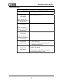
1
TECHNICAL INFORMATION W1900 Series Clothes Washers © 2007 Miele USA W1900 Series Clothes Washers Technical Information W1900 Series Clothes Washers - Table of Contents 1.0 Construction and Design.........................................................................6 1.1 1.2 1.3 1.4 1.5 1.6 2.0 Installation ..............................................................................................17 2.1 2.2 2.3 3.0 General Operation ...................................................................................... 23 Additional Function Pushbuttons ................................................................ 23 Description of Function .........................................................................25 4.1 4.2 4.3 4.4 4.5 4.6 4.7 4.8 4.9 4.10 4.11 4.12 4.13 4.14 4.15 4.16 4.17 4.18 4.19 5.0 Electrical Requirements ............................................................................. 17 Plumbing Requirements ............................................................................. 18 Installation Procedure................................................................................. 19 Commission and Operation ..................................................................23 3.1 3.2 4.0 Appliance Overview...................................................................................... 6 Overview of Controls .................................................................................... 7 Technical Data ........................................................................................... 11 Dispenser Assembly................................................................................... 13 Layout of Electrical Components W1903, W1918, W1926 & W1930....... 15 Layout of Electrical Components W1966 & W1986.................................. 16 Casing Assembly........................................................................................ 25 Electro-Mechanical Door Lock.................................................................... 25 Miele Eco Wash System ............................................................................ 26 Drum Suspension ....................................................................................... 27 Heating Circuit Information ......................................................................... 28 Water Level Switch..................................................................................... 29 Water Control System – Intake................................................................... 29 Water Control System – Rinses ................................................................. 30 Inlet Hose(s) Filters .................................................................................... 30 Inlet Valves................................................................................................. 30 Dispenser Assembly................................................................................... 30 Non-Return Valve & Drain Venting............................................................. 31 Main Motor ................................................................................................. 32 Motor Speed Control .................................................................................. 32 Tachogenerator .......................................................................................... 32 Imbalance Monitoring ................................................................................. 33 Motor Circuit ............................................................................................... 33 Program Control ......................................................................................... 34 Heater Relays............................................................................................. 34 Service and Maintenance ......................................................................35 5.1 5.2 5.3 5.4 5.5 5.6 Dispenser Drawer – Removal..................................................................... 35 Appliance Lid – Removal............................................................................ 36 Front Service Panel – Access .................................................................... 36 Door Seal – Replacement .......................................................................... 37 Air Trap – Replacement.............................................................................. 38 Heater Element(s) – Replacement ............................................................. 39 2 W1900 Series Clothes Washers Technical Information W1900 Series Clothes Washers - Table of Contents (continued) 5.7 5.8 5.9 5.10 5.11 5.12 5.13 Inlet Valve – Replacement.......................................................................... 39 Manual Draining and Filter Removal .......................................................... 40 Drain Pump - Replacement ........................................................................ 41 Main Motor – Carbon Brush Replacement ................................................. 42 Control Electronic – Removal..................................................................... 43 Power Supply Electronic - Removal ........................................................... 44 Determining Which Electronic Requires Replacement (Electronic Test Procedure).................................................................................................. 45 5.14 Water Level Switch - Replacement ............................................................ 47 5.15 Heater Relays - Access.............................................................................. 48 6.0 Fault Diagnosis ......................................................................................49 6.1 6.2 6.3 Service Mode - W1903, W1918, W1926 & W1930 .................................... 49 Service Mode - W1966 and W1986 ........................................................... 50 Fault Codes ................................................................................................ 51 6.3.1 Fault Code – Definitions (W1966 & W1986 Only) ........................... 52 6.4 Programming Mode .................................................................................... 54 6.5 Description of Programmable Options........................................................ 57 6.6 Special Features ........................................................................................ 61 6.6.1 Electronic Program Lock ................................................................. 61 6.6.2 Child Safety Lock............................................................................. 61 6.6.3 Demonstration Mode ....................................................................... 62 6.7 Fault Indicators ........................................................................................... 63 6.8 Porthole Door is locked / unable to access service door ........................... 67 6.9 Customer reports water leaks from front left side of the appliance. .......... 67 6.10 W1966 & W1986 not functioning correctly, after Control Electronic Replacement .............................................................................................. 67 6.11 W1900 series not functioning correctly, after Control Electronic Replacement .............................................................................................. 68 3 W1900 Series Clothes Washers Technical Information W1900 Series Clothes Washers – List of Figures Figure 1-1: Figure 1-2: Figure 1-3: Figure 1-4: Figure 1-5: Figure 1-6: Figure 1-7: Figure 1-8: Figure 1-9: Appliance Overview (typical W1900 series washer).................................... 6 Overview of Controls (W1903 & W1918)..................................................... 7 Overview of Controls (W1926 & W1930)..................................................... 8 Overview of Controls (W1966)..................................................................... 9 Overview of Controls (W1986)................................................................... 10 5 Kilogram Dispenser (W1903, W1918, W1930 & W1930i) ...................... 13 6 Kilogram Dispenser (W1966 & 1986) ..................................................... 14 Overview of Components (W1903, W1918, W1930 & W1926) ................. 15 Overview of Components (W1966 & W1986)............................................ 16 Figure 2-1: Figure 2-2: Figure 2-3: Figure 2-4: Figure 2-5: Turning the left Shipping Strut counterclockwise....................................... 19 Turning the right Shipping Strut clockwise................................................. 19 Removing the Strut Support Assembly...................................................... 20 Plugging the Shipping Strut Holes. ............................................................ 20 Adjusting the legs to level the appliance.................................................... 21 Figure 4-1: Figure 4-2: Figure 4-3: Figure 4-4: Figure 4-5: Figure 4-6: Figure 4-7: Eco Wash System ..................................................................................... 26 Drum Suspension Components................................................................. 27 Increased in water volume = increased pressure against the Level Switch. .............................................................................................. 29 Dispenser Assembly .................................................................................. 30 Non-return valve ........................................................................................ 31 Main Motor Assembly ................................................................................ 32 Motor circuit ............................................................................................... 33 Figure 5-1: Figure 5-2: Figure 5-3: Figure 5-4: Figure 5-5: Figure 5-6: Figure 5-8: Figure 5-9: Figure 5-10: Figure 5-11: Figure 5-12: Removing the dispenser drawer ................................................................ 35 Service Access .......................................................................................... 36 Replacing the door seal ............................................................................. 37 Air Trap and Level Switch Components .................................................... 38 Heater Element.......................................................................................... 39 Drain pump removal .................................................................................. 41 Removing Control Electronic ..................................................................... 43 Removing the Power electronic ................................................................. 44 Ribbon Cable with pin 1 position noted. .................................................... 45 Water level switch...................................................................................... 47 Heater relays with bracket ......................................................................... 48 4 W1900 Series Clothes Washers Technical Information W1900 Series Clothes Washers – List of Tables Table 1-1: Table 1-2: Technical Data (Continued on Table 1-2)................................................... 11 Technical Data (Continued from Table 1-1) ............................................... 12 Table 4-1: Table 4-2: NTC Temperature Sensor - Resistance ..................................................... 28 Imbalance Monitoring ................................................................................. 33 Table 6-1: Table 6-2: Table 6-3: Table 6-4: Service Mode Functions (W1903, W1918, W1926 & W1930).................... 49 Service Mode Functions (W1966 & W1986) .............................................. 50 Fault Codes (W1966 & W1986).................................................................. 51 Programming Mode Functions for W1966 & W1986 (Continued on Table 6-5) ................................................................................................... 55 Table 6-5: Programming Mode Functions for W1966 & W1986 (Cont. from Table 6-5, Cont. on Table 6-6)..................................................................................... 56 Table 6-6: Programming Mode Functions for W1966 & W1986 (continued from Table 6-5) ............................................................................................................. 57 Table 6-7: Fault Indicators (Continued on Table 6-8) .................................................. 63 Table 6-8: Fault Indicators (Continued from Table 6-7) (Continued on Table 6-8)...... 64 Table 6-9: Fault Indicators (Continued from Table 6-8) (Continued on Table 6-10).... 65 Table 6-10: Fault Indicators (Continued from Table 6-9)............................................... 66 5 W1900 Series Clothes Washers Technical Information 1.0 Construction and Design 1.1 Appliance Overview 1 2 3 4 Supply Cable High Pressure Intake Hoses Flexible Drain Hose, With Detachable Swivel Elbow Detergent Dispenser Drawer 5 6 7 8 Control Panel Drum Door Access Panel for Lint Filter and Drain Pump Four Height Adjustable Legs Figure 1-1: Appliance Overview (Typical W1900 Series Washer) 6 W1900 Series Clothes Washers Technical Information 1.2 Overview of Controls W1903 W1918 Figure 1-2: Overview of Controls (W1903 & W1918) 7 W1900 Series Clothes Washers Technical Information W1926 W1930 Figure 1-3: Overview of Controls (W1926 & W1930) 8 W1900 Series Clothes Washers Technical Information W1966 Figure 1-4: Overview of Controls (W1966) 9 W1900 Series Clothes Washers Technical Information W1986 Figure 1-5: Overview of Controls (W1986) 10 W1900 Series Clothes Washers Technical Information 1.3 Technical Data W1903 W1918 W1926 W1930 W1966 W1986 331/4 – 337/8” (845mm + 860mm) 331/2” + 1/2”/-1/4” (850mm +10/-0,5 mm) Height 331/4” – 337/8” 331/4 – 337/8” 331/2” + 1/2”/-1/4” (850mm + 10/-0,5 mm) Width 23 5/8” (600 mm) 23 5/8” (600 mm) 23 5/8” (600 mm) 23 5/8” (600 mm) 23 5/8” (600 mm) Depth (inc. distance from wall) 24” (610 mm) 24” (610 mm) 28 1/4” (715 mm) 24” (610 mm) 28 1/4” (715 mm) Weight 220 lbs. (100 kg) 220 lbs. (100 kg) Capacity 11 lbs. (5 kgs.) dry laundry 11 lbs. (5 kgs.) dry laundry 13 lbs. (6 kgs.) dry laundry 11 lbs. (5 kgs.) dry laundry 13 lbs. (6 kgs.) dry laundry Rated Load 2.8 kW 2.8 kW 2.8 kW 2.8 kW 2.8 kW Circuit Breaker 15 amp 15 amp 15 amp 15 amp 15 amp 15-145 psi (1–10 bar) 15-145 psi (1–10 bar) 15-145 psi (1–10 bar) ¾” in. ¾” in. ¾” in. hose hose hose thread thread thread Hot & Cold Cold Only Hot & Cold ¾” in. hose thread Hot & Cold ¾” in. hose thread Hot & Cold Water Pressure Water Connection 15-145 psi 15-145 psi (1–10 bar) (1–10 bar) 252 lbs. (114 220 lbs. (100 252 lbs. (114 kg) kg) kg) Table 1-1: Technical Data (Continued on Table 1-2) 11 W1900 Series Clothes Washers Technical Information W1903 W1918 W1926 W1930 W1966 W1986 Drain Connection 5’ hose 1 ¼” OD 1” ID 5’ hose 1 ¼” OD 1” ID 5’ hose 1 ¼” OD 1” ID 5’ hose 1 ¼” OD 1” ID 5’ hose 1 ¼” OD 1” ID Maximum Drain Height 4’ 4’ 4’ 4’ 4’ 120 V/240 (208) V Power Requirement single phase s 60 Hz 120 V/240 (208) V single phase 60 Hz 120 V/240 120 V/240 120 V/240 (208) V (208) V (208) V single single single phase phase phase 60 Hz 60 Hz 60 Hz 5’ cable Power Cord / NEMA 15Plug 30 plug 5’ cable NEMA 15-30 plug 5’ cable 5’ cable 5’ cable NEMA 15- NEMA 15-30 NEMA 15-30 30 plug plug plug Spin Speed 600-1200 rpm 400-1600 rpm 600-1200 rpm 400-1600 rpm 400-1200 rpm Temperature Control Cold to 190º Cold to 190º Cold to 190º Cold to 170º Cold to 190º Floor Load 360 lbs 360 lbs 682 lbs 360 lbs 682 lbs Table 1-2: Technical Data (continued from Table 1-1) 12 W1900 Series Clothes Washers Technical Information 1.4 Dispenser Assembly 5 Kilogram Models (W1903, W1918, W1930 & W1930i) Detergent dispenser drawer - for the pre-wash Compartment Compartment - for the main wash. - (with lid) for fabric softener or starch. Compartment Figure 1-6: 5 Kilogram Dispenser (W1903, W1918, W1930 & W1930i) 13 W1900 Series Clothes Washers Technical Information 6 Kilogram Models (W1926, 1966, & 1986) Detergent dispenser drawer - for the pre-wash Compartment Compartment - for the main wash. Compartment - (with lid) for fabric softener or starch. Figure 1-7: 6 Kilogram Dispenser (W1966 & 1986) Note: The largest compartment is always the Main Wash. 14 W1900 Series Clothes Washers Technical Information 1.5 Layout of Electrical Components W1903, W1918, W1926 & W1930 A2 B1 K1/1 M5 M8 1N1 2N1 R1, R2 Door Lock Level switch Relay – Heating Motor – Drum drive Motor – Drain pump Power module Control module Heating R30 S1 S16 X3/1 Y1-Y3 Y12 Z1-Z3 Temperature sensor Selector switches – Additional functions Selector switch – Spin Speed Mains terminal strip Inlet valves Hot water valve Interference suppressor Figure 1-8: Overview of Components (W1903, W1918, W1930 & W1926) 15 W1900 Series Clothes Washers Technical Information 1.6 Layout of Electrical Components W1966 & W1986 1 2 3 4 5 6 Hot Water Valve Cold Water (Triple) Valve Main Motor & Interference Capacitor Main Motor Drain Pump Heating Element (2) 7 Heater NTC 8 Heater Relays 9 Control Electronic 10 Input Board 11 Power Electronic 12 Door Lock Figure 1-9: Overview of Components (W1966 & W1986) 16 W1900 Series Clothes Washers Technical Information 2.0 Installation The Shipping Struts must be completely removed prior to any operation and / or testing. Ensure the appliance is being installed on a suitable surface. Chlorine Bleach is not recommended. Only detergent carrying an “H.E.” (High Efficiency) designation should be used. The appliance comes equipped to operate using only powder detergent; to use liquid detergents an optional detergent drawer insert is required - call Miele Technical Support to order. The machine must be perfectly level to ensure safe and proper operation. To perform a stacked installation an approved Miele Stacking Kit that matches the exact model numbers must be used. The washer must be the lower appliance and installed first. Note: A Laundry Stand and a Stacking Kit cannot be used together. 2.1 Electrical Requirements 120/240 (208) Volt, 60Hz., 15 Amp breaker Washers are equipped with a 4 wire power cord consisting of L1, L2, N and Ground; equipped with a NEMA 14-30 plug, for connection to a NEMA 14-30 receptacle. Note: For proper appliance operation a Neutral is required. Note: If you do not have a dedicated 15 Amp circuit for this appliance, but have a NEMA 14-20 or NEMA 14-30, 240V, 30 Amp outlet, you may be able to use a Miele “Easy Installation Kit” to simplify the electrical connection. For further information refer to Electrical Information pages in the Installation Manual. Do not cutoff / remove the plug from the power cord. 17 W1900 Series Clothes Washers Technical Information 2.2 Plumbing Requirements Water Inlet All W1900 series washer (except the W1903) are equipped with two Water Inlet Hoses. Connect the Cold Water Intake Hose (blue mark) to the Cold Water Valve and the Hot Water Intake Hose (red mark) to the Hot Water Valve. The W1903 is equipped with a single Inlet Hose; that must be connected to a cold water supply. The water pressure must be within 15-145 psi (1-10 bar). If the water pressure is greater than 145 psi (10 bar), a Pressure Reducer must be installed. If the water pressure is below 15 psi (1 bar), insufficient water may be available for a complete fill. The Water Intake Hoses are equipped with Screen Filters - do not remove these filters. Note: For customers requesting a “cold water only connection” on washers equipped with Dual Inlet Hoses a “Y” adapter (available at most hardware stores) can be utilized. Both Inlet Hoses (hot and cold) should be connected to the adapter. Drain Connection The appliance is equipped with a 5 ft. (1.5 m) drain hose with a maximum delivery height of 4ft. (1.2 m) which can be connected as follows: 1. Directly into a sink: hook the hose over the edge of the sink and secure it firmly (i.e. by tying the hose to the water faucet etc...). 2. To a stand pipe: place the Drain Hose into a 1 1 /2" (38 mm) stand pipe and secure in place. 3. To a floor drain: The machine is equipped with an Airgap/AntiSiphoning System so that no minimum drain height is required. Important! Ensure all connections are secure & hoses are free from sharp bends and kinks. 18 W1900 Series Clothes Washers Technical Information 2.3 Installation Procedure 1. Lift the machine from the shipping pallet and move it to the installation site. Do not lift the machine by the Drum Door. Note: Ensure that the machine feet and the floor are dry to prevent slippage during the spin cycle. 2. REMOVE THE SHIPPING STRUTS - by performing the following: Turn the left Shipping Strut 90° counterclockwise Figure 2-1: Turning the left Shipping Strut Counter Clockwise. Turn the right Shipping Strut 90° clockwise. Figure 2-2: Turning the right Shipping Strut Clockwise. 19 W1900 Series Clothes Washers Technical Information Remove the two Struts and Support Plate Assembly. Figure 2-3: Removing the Strut Support Assembly Figure 2-4: Plugging the Shipping Strut Holes 20 W1900 Series Clothes Washers Technical Information Note: Movement of the machine without the Shipping Struts in place should be kept to a minimum. NEVER operate the appliance with the Shipping Struts installed. The Shipping Struts should be stored in a safe place and must be reinstalled if the machine is going to be moved. Reinstallation can be performed by reversing the above procedure. 3. Refer to Figure 2-5. To level the appliance, perform the following: Figure 2-5: Adjusting the Legs to Level the Appliance. a. Tip the machine slightly and place a support, such as a block of wood, underneath it. b. Unscrew each of the four feet as much as necessary by turning both the foot 1 as well as the locking ring 2 counterclockwise using a screwdriver - as shown. c. Remove the support, stand the machine on its feet and check to see if it is level. d. Repeat this procedure as often as necessary until the machine stands level. e. Turn each locking ring until it is tight against the bottom of the machine frame. 21 W1900 Series Clothes Washers Technical Information Caution! All four locking rings must be tight against the bottom of the machine. Operating an unleveled appliance can cause damage to both the appliance and its surroundings. After the Clothes Washer has been leveled, install the Stacking Kit (if being used) - refer to the Installation Manual for further information. 4. Perform the Plumbing Connections. 5. Ensure the electrical supply matches the specifications on the Data Tag. Perform the Electrical Connection. 6. Perform an operation check of the appliance. 22 W1900 Series Clothes Washers Technical Information 3.0 Commission and Operation 3.1 General Operation 1. Prepare the wash load 2. Press the “Door” Button to open the door 3. Load the machine 4. Close the Machine Door 5. Add detergent 6. Turn the Program Selector to Finish / Start 7. Press the “ON/OFF” Button 8. Press any desired “Additional Function” Pushbuttons 9. Select the final spin speed 10. Turn the Program Selector to the desired program 3.2 Additional Function Pushbuttons Pre-Wash Use for heavily soiled or stained laundry items. Requires additional detergent be added to Pre Wash Compartment of the Dispenser Drawer. Water Plus Slightly increases the water level. Usually used for: Particularly delicate fabrics (in addition to the “Gentle Wash” Option) Areas with hard water (were additional detergent is required) Areas with soft water (to enhance washing and rinsing results) People who are allergic or sensitive to detergent. Rapid Wash Offers a quick wash cycle (approx. 38 minutes) Can be used with or without a Pre-Wash. (is available in all programs) Delay Start Upon turning on the machine, the “Delay Start” Lamp will be blinking. The start of the program can be delayed up to 9 hours and 30 minutes. Each press of the button adds 30 minutes. Gentle Wash Drum movement is reduced by half for gentle washing of slightly soiled laundry items, or delicate fabrics which otherwise tend to pill. 23 W1900 Series Clothes Washers Technical Information Soak For heavy soiling and stubborn stains (e.g. blood, grease, cocoa), that require soaking before the main wash. W1966 Use the Soak button to toggle between the two settings: Soak LED on = add a 120 minute soak to the program Soak LED off = no soak (default) W1986 Each Press of the Soak Button adds 30 minutes (up to 6 hours max) of soak time to the wash program. Extended For laundry with stubborn or old stains. The longer wash time works to relax fabrics and release stains. The total time for the wash program will be extended. Sensitive Adds an additional final. Buzzer A buzzer can be selected to signal the end of the wash program. 24 W1900 Series Clothes Washers Technical Information 4.0 Description of Function 4.1 Casing Assembly The clothes washer casing consist of a one piece assembly comprised of the rear wall, side walls and base of the appliance. The front of the appliance is fitted with a removable Stabilizer Brace and a Service Access Panel. 4.2 Electro-Mechanical Door Lock The Door Lock Assembly is an electro-mechanical device, that is energized (to unlock the door) when the user presses the Door Button. The circuit voltage, appearance and part numbers vary by model number. Refer to the model specific parts list for further information. The Door Lock System incorporates a safety system to prevent the door from opening if: x There is water in the machine (as determined by the Level Switch) x The drum is moving (as determined by the Tacho-Generator and / or Electronic). 25 W1900 Series Clothes Washers Technical Information 4.3 Miele Eco Wash System All Miele Electronic Clothes Washers use the Miele Eco Wash System to avoid wasting detergent by sealing the Drain Outlet with a Ball Valve (Refer to Figure 4-1 – Item 1). This ensures that all the detergent is retained in the suds container where it can be quickly dissolved. Water is taken into the suds container via the detergent dispenser, concertina hose and siphon odor trap. Figure 4-1: Eco Wash System 26 W1900 Series Clothes Washers Technical Information 4.4 Drum Suspension A characteristic feature of Miele Washers is the Suds Container Suspension Assembly; as illustrated in Figure 4-2. The mechanical forces that develop during appliance operation is transferred (via the bearing and the bearing cross) to the shocks and springs for dampening. Figure 4-2: Drum Suspension Components 27 W1900 Series Clothes Washers Technical Information 4.5 Heating Circuit Information There are two Heating Elements mounted between the drum and the suds container. The Heating Elements are responsible for heating water to the selected temperature. The Heater Elements are controlled via two (2) Relays, energized by the Electronic. The temperature of the water is monitored by the NTC (Negative Thermal Coefficient) Sensor. As the temperature increases, the resistance decreases. The resistance value is monitored by the Electronic and is used to calculate the temperature of the water. Refer to the NTC Temperature Sensor Operation Table (Table 4-1) below for specific values. NTC Temperature Sensor - Operation Table 4-1: NTC Temperature Sensor - Resistance 28 W1900 Series Clothes Washers Technical Information 4.6 Water Level Switch The Water Level Switch monitors the water level inside the drum. The switch operates by closing specific electrical contacts depending on the amount of pressure against its internal diaphragm. As the water level inside the drum increases, the pressure against the switch also increases. The changes in the switching are monitored by the Electronic and are used to calculate the exact water level inside the appliance. This design offers the benefit of keeping the water level consistent, regardless of the absorption rate of the laundry. Figure 4-3: Increased in water volume = increased pressure against the Level Switch. Note: On the W1966 and W1986 model clothes washers, the Water Level Switch is incorporated into the Control Electronic. During the heating stage of the wash program the Water Level Switch is used by the Electronic System to ensure water is present before the heating circuit is activated. In addition the circuit is monitored for any changes in pressure. Sudden changes in pressure usually indicate an oversudsing condition. The Electronic System then automatically performs the necessary adjustments to rectify the condition. 4.7 Water Control System – Intake During the initial water intake, the Electronic monitors the duration of time until the Water Level Switch is actuated. This value is used so that certain wash variables (i.e. wash time, number of rinses) can be controlled during the program. If water level 1 is not reached within the programmed “water intake time” (2 or 4 minutes), the Inlet Valves are closed; the program is cancelled and the Drain Pump is operated for 90 seconds. 29 W1900 Series Clothes Washers Technical Information 4.8 Water Control System – Rinses During the rinse segment of the program if Level 1 is not reached within 90 seconds of water intake; the rinse duration is extended from 4.5 to 6.5 minutes by the Electronic. 4.9 Inlet Hose(s) Filters The Water Inlet Hoses are equipped with two filters to protect the Water Valves. One filter is fitted at the end of the hose (directly at the water connection). The second filter is fitted within the threaded connections (on the rear of the washer). 4.10 Inlet Valves All washers (except the W1903) are equipped with a single ElectroMechanical Water Valve; to control hot water entering the appliance. The cold water supply to the washer is controlled via a Triple Valve Assembly. Although the component is physically one item; each valve is plumbed (and electrically energized) separate to provide water control for the: x Pre-Wash x Main-Wash x Rinse 4.11 Dispenser Assembly The Dispenser Assembly distributes the incoming water to separate compartments within the Dispenser Drawer. Figure 4-4: Dispenser Assembly 30 W1900 Series Clothes Washers Technical Information 4.12 Non-Return Valve & Drain Venting Refer to Figure 4-5 – Non-Return Valve. During the drain segment of a program the Ball-Seat Valve, (item 1) closes preventing dirty water from re-entering the Suds Container. Should the drain connection on site be lower than the water level (within the appliance) the valve opens to prevent any siphoning of water from the appliance. Figure 4-5: Non-Return valve 31 W1900 Series Clothes Washers Technical Information 4.13 Main Motor The Main Motor operates on DC (Direct Current) and operates at various speeds. The front section of the motor is removable for access to the Tachogenerator and Motor Brushes. The front section is removable with the motor installed, allowing it to remaining connected to the drives. Figure 4-6: Main Motor Assembly 4.14 Motor Speed Control Motor speed is controlled via the Electronic. The Electronic controls the switching for the voltage applied to the motor and the field windings. 4.15 Tachogenerator The Tachogenerator monitors the status of the Main Motor. As the motor turns, the Tachogenerator creates pulses. These pulses are monitored by the Electronic for: x x x Determining if the motor is turning. (The Door Button is disabled by the Electronic if drum is > 7rpm) For imbalance monitoring (via erratic pulses) To monitor motor speed (used to regulate the motor speed) 32 W1900 Series Clothes Washers Technical Information 4.16 Imbalance Monitoring Range 1 Range 2 Range 3 Range 4 0-0.7 kg No reduction in spin speed. 0.7-1.1 kg If imbalance exists after 3 attempts to redistribute the load then the spin speed is limited to 2nd highest value (exact rpm varies by model number) 1.1-2.0 kg If imbalance exists after 3 attempts to redistribute the load then the spin speed is limited to 3rd highest value (exact rpm varies by model number) > 2 kg Load distribution attempts continually made until imbalance is reduced or the program time has completed. Table 4-2: Imbalance Monitoring 4.17 Motor Circuit A B C D E F Change Field Relay (spin/ wash actuation) Motor Direction Relay Temperature Limiter Field Windings Rotor Windings Tachogenerator Figure 4-7: Motor Circuit 33 W1900 Series Clothes Washers Technical Information 4.18 Program Control The Program Control consist of the Electronic Control Unit (Upper Electronic) and the Power Supply Electronic Unit (Lower Electronic).s Functions of the Electronic Control Unit include: Precise program and component control Monitoring circuits (i.e. motor speed, temperature etc…) A Fault Finding and Service Mode Program Mode (W1966 & W1986) Functions of the Power Supply Electronic include: Providing the Electronic Control Unit with the “zero crossover point signal” (used for timing) Component switching (via relays and thyristors) On models equipped with the Delayed Start feature, a third electronic is installed. This Electronic provides the delay control and also contains the numeric LEDs, for displaying the remaining wash time to the user. Important! If an Electronic is suspected to be faulty; the "Electronic Test" procedure must be performed. Refer to Section 5.13 – Determining Which Electronic Requires Replacement. 4.19 Heater Relays Switching of the two Heater Elements is performed via two relays. Both relays are controlled by the Electronic, and are energized when: 1. The program calls for heating AND 2. The water level is at an acceptable level (as determined by the Level Switch). Service Tip: Even in the Service Mode the Water Level Switch must be satisfied before the Heating Relays & Elements can be powered on. 34 W1900 Series Clothes Washers Technical Information 5.0 Service and Maintenance Warning! Prior to performing Service and/or Maintenance procedures... The appliance must be disconnected from the main power; by unplugging the appliance and/or shutting off the circuit breaker. 5.1 Dispenser Drawer – Removal 1. Slide the Drawer out from the Control Panel. 2. Press down on the Release Tab (Refer to Figure 5-1, Item 1). 3. Pull the Drawer out, releasing it from the appliance. Figure 5-1: Removing the Dispenser Drawer 35 W1900 Series Clothes Washers Technical Information 5.2 Appliance Lid – Removal 1. Refer to Figure 5-2 – Service Access. 2. Remove screws “A” from the edge of the lid. 3. Pull the Lid forward. Lift up the front of the Lid and slide it to the rear of the appliance. 4. Lift the Lid from the appliance. 5.3 Front Service Panel – Access Figure 5-2: Service Access 1. Remove the Dispenser Drawer – Refer to Section 5.1. 2. Refer to the figure 5-2. Remove the two screws (Item 1). 3. Open the Washer Door and remove the three 10 mm hex bolts (Item 2). 4. Open the Front Panel from the left (hinged on the right). Service Tip: Before closing the Front Panel, ensure the manual door release is routed through the slot in the Filter Housing Assembly. Refer to Figure 5-2, Item 3. 36 W1900 Series Clothes Washers Technical Information 5.4 Door Seal – Replacement Refer to Figure 5-3 – Replacing the Door Seal. 1. Open the Front Service Panel – Refer to Section 5.3. 2. Unclip the front edge of the Door Seal from the Font Plate (Item 1) and fold back. 3. Loosen the clamping ring and remove the seal and ring (Item 2). To fit a new seal, replace parts in reverse order. Figure 5-3: Replacing the Door Seal 37 W1900 Series Clothes Washers Technical Information 5.5 Air Trap – Replacement Refer to Figure 5-4 – Air Trap and Level Switch Components. 1. Open the Front Service Panel – Refer to Section 5.3. 2. Manually drain all remaining water – Refer to Section 5.8. 3. Pull the Air Trap (item 3) outward to remove from the appliance. 4. Remove the Air Hose (item 2). 5. Remove the Seal. Re-Installation 1. Install the new Seal. 2. Install the new Air Hose. 1 – Level Switch 2 – Air Hose 3 – Air Trap Figure 5-4: Air Trap and Level Switch Components Important! Ensure the Air Hose is: Routed correctly NOT being pinched by any of the retaining clips NOT resting against any edge of the appliance frame Service Tip: The lug on the Air Trap must engage in the corresponding opening. 38 W1900 Series Clothes Washers Technical Information 5.6 Heater Element(s) – Replacement 1. Open the Front Service Panel – Refer to Section 5.3. 2. Ensure the unit is unplugged. 3. Note wiring connections to the heaters. Unplug the electrical connections to the heater(s). 4. Pull straight out on the Heater Element to remove. 5. Install new seals and ground rings to each new element. Apply a thin film of soap solution to lubricate the seals and fit the elements into position. 6. Attach the electrical connection(s) to each heater. Service Tip: Ensure the element is inserted under its retaining clip. Retaining Clip Inside Suds Container Figure 5-5: Heater Element 5.7 Inlet Valve – Replacement 1. 2. 3. 4. Turn off the water supply to the appliance. Remove the Water Inlet Hose from the Valve. Remove the top cover from the appliance – Refer to Section 5.2. Loosen the hose clamps. Service Tip: Ensure the hoses on the Cold Water Valve are re-connected in the correct locations – mark hoses as necessary. 5. Remove each hose (1 by 1) and attach to the new Valve. 6. Remove the screw(s) on the rear panel of the washer, lift old Valve Assembly from machine to remove. 39 W1900 Series Clothes Washers Technical Information 5.8 Manual Draining and Filter Removal Service Tip: Even if the appliance does not appear to have water inside the drum area, typically 2 quarts of water can still be drained from the appliance via the Manual Drain. Always have a suitable container ready for the water. 1. Open the Filter Access Door. 2. Place a suitable container underneath the Drain Tube. 3. Turn the Filter Cap counter clockwise 2 - 3 times. Do not completely remove the filter. Service Tip: In the event the container being used becomes filled, simply tighten the filter (clockwise) to stop the water flow. And repeat steps 2-3 until no more water drains from the tube. Once the water stops flowing… 5. Continue turning the filter counterclockwise to remove. 6. Clean out any foreign objects or lint from the filter. 7. Check that the Drain Pump Impeller (in the back of the chamber) rotates freely by spinning with your hand. 8. Remove any detergent deposits, excess water etc... 9. Ensure the filter threads are clean, and place filter into position and secure by turning clockwise. Service Tip: On model W1930i use the Drain Hose and Stopper, located in the plinth area to manually drain the washer. Caution! Water drains from the hose immediately when the plug is removed. Pinch hose / connect the Stopper to stop the water flow. 40 W1900 Series Clothes Washers Technical Information 5.9 Drain Pump – Replacement 1. 2. 3. 4. 5. Open the Front Service Panel – Refer to Section 5.3. Manually drain all remaining water – Refer to Section 5.8. Remove the filter – Refer to Section 5.8. Disconnect the Electrical Connection on the Pump. Refer to Figure 5-6. Release and slide the red catch (item 1) in the direction of the arrow and remove. 6. Twist the pump 900 to remove. Figure 5-6: Drain Pump Removal 41 W1900 Series Clothes Washers Technical Information 5.10 Main Motor – Carbon Brush Replacement 1. 2. 3. 4. Open the Service Panel – Refer to Section 5.3. Unscrew the Plastic Motor Cover. Remove 4 screws from the Brush/Tachogenerator Module (A). Pull module (Item 1) away from motor to remove. Should the Tachogenerator or Overheat Protection Device require replacement, the entire module is replaced as a single component. Motor Brushes should always be replaced as a set (2 brushes). Service Tip: Before installing the module, press the brushes into their guides (they will be held by a retaining clip). Once the module is secured to the motor, release the brushes by pushing the brushes from behind with a small screwdriver or other suitable tool. 42 W1900 Series Clothes Washers Technical Information 5.11 Control Electronic – Removal Service Tip: Make note / mark the position of the ribbon cables, as they can easily be installed in reverse (causing the appliance to malfunction). 1. Open the Service Panel – Refer to Section 5.3. 2. Refer to Figure 5-8. Disconnect the plug. 3. Remove the Ribbon Cable (Item 2) from its guide (Item 1) and disconnect it from the Electronic. 4. Remove the 3 screws (Item 3). 5. Remove the Electronic. Figure 5-8: Removing Control Electronic 43 W1900 Series Clothes Washers Technical Information 5.12 Power Supply Electronic - Removal 1. Open the front Service Panel – Refer to Section 5.3. 2. Refer to Figure 5-9. Use a screwdriver and release the Retainer Clip (Item 1). 3. Move the Electronic forward to release the retaining lug. Figure 5-9: Removing the Power electronic 44 W1900 Series Clothes Washers Technical Information 5.13 Determining Which Electronic Requires Replacement (Electronic Test Procedure) Correct zero crossover point (NND) recognition is required by the microprocessor to provide a reference point for activating relays and thyristors. The zero crossover point of the sine wave is the basis for the time measurement of the microprocessor. If the Electronic Unit fails to detect the zero crossover of 3 half waves of the AC power sine wave, a fault is registered and the microprocessor resets. The current program is cancelled and the LED’s switch off. The appliance can only be restarted after switching it off and then back on; and selecting a program. Because the possibility exists that either Electronic could present the same type of fault condition; the following procedure ensures the correct component is diagnosed / replaced. Service Tip: In the event the Control Electronic Unit or the Power Electronic Unit is suspected to be faulty, this procedure must be performed. Figure 5-10: Ribbon Cable with Pin 1 Position Noted 45 W1900 Series Clothes Washers Technical Information W1918 /-30 /-26 /-66 /-86 Clothes Washers Electronic Check 1. Turn the appliance OFF. 2. Locate and unplug the ribbon cable connector from the Upper Electronic Board. 3. Close the Door. 4. Set the program selector to the START position. 5. Turn the appliance ON. 6. Ensure the Ribbon Cable is secured to the Lower Electronics, only. 7. Counting from left to right, locate pins 9 and 10 on the unplugged ribbon cable connector. 8. Measure the DC voltage between pins 9 and 10. Voltage from 4VDC to 6VDC is acceptable 9. Locate pins 12 and 13 on the unplugged ribbon cable connector. 10. Measure the voltage between pins 12 and 13. Voltage from 25VDC to 33 VDC is acceptable. Are both voltages within tolerance? NO YES Lower electronic is OK Replace the Lower electronic 11. 12. 13. 14. 15. Turn the appliance OFF. Reconnect the ribbon cable to the Upper Electronic. Locate pins 10 and 11 on the Lower Electronic Ribbon Cable Connector. Turn the appliance ON. Measure the voltage between pins 10 and 11. Voltage from 1.4VDC to 2.4VDC is acceptable. Is the voltage within tolerance? NO YES Both Electronics are OK / Troubleshoot elsewhere. Replace the Upper Electronic 46 W1900 Series Clothes Washers Technical Information 5.14 Water Level Switch - Replacement Note: This procedure can only be performed on W1903, W1918, W1926 and W1930 clothes washers. The W1966 and W1986 washer are equipped with a Level Switch integrated into the Control Electronic. The Level Switch cannot be replaced separately. Figure 5-11: Water Level Switch 1. 2. 3. 4. 5. Open the Front Service Panel – Refer to Section 5.3. Unplug the electrical connection from the Level Switch. Remove the single retaining screw. Lift the Level Switch away from the appliance. Disconnect the Air Hose Connection at the bottom of the switch. 47 W1900 Series Clothes Washers Technical Information 5.15 Heater Relays - Access The Heater Relays are secured to single bracket. The bracket is secured to the frame near the 3 o’clock position of the drum. 1. Open the Front Service Panel – Refer to Section 5.3. 2. Remove the screw securing the bracket to the frame. 3. Pull the bracket away from the frame to access the relay(s). Figure 5-12: Heater Relays with Bracket 48 W1900 Series Clothes Washers Technical Information 6.0 Fault Diagnosis 6.1 Service Mode - W1903, W1918, W1926 & W1930 Access 1. Turn off the machine. Close the Door. 2. Turn the Program Selector Switch to 12 o’clock. 3. Turn the unit on with the On/Off Switch. 4. Push the “Pre-Wash” Button in & out 3 times within 4 seconds. Acknowledgement Indicator Successful access into the Service Mode is indicated by a flashing “PreWash” LED. Navigation Turn the Program Selector Switch to the desired position in accordance with the Table 6-1. Selector Switch Position COTTONS 190 COTTONS 170 on W1903 COTTONS 180 COTTONS 160 on W1903 Function LED’s Pre-Wash Valve (Y1) opens until water level 1 is reached. Heating to 95º then begins. Main wash & Check Drain LED’s are on. Main Wash Valve (Y2) opens until water level 3 is reached. Rinse 1-2 & Drain LED’s are on. W1903: Rinse/Rinse & Hold LED’s on COTTONS 150 on W1903 Main Wash Valve (Y2) and Rinse Valve (Y3) open until water level 3 is reached. Rinse 3-4 & Faucet LED’s are on. COTTONS 140 (not used) Finish LED is on. COTTONS 120 Drain Pump operates. Drain & Faucet LED’s are on. COTTONS 105 Drum rotates @ 55/40 rpm w/ reverse action. COTTONS 155 COTTONS 85 PERM PRESS 140 Drain Pump operates, drum spins to set spin speed on control panel (up to 1200rpm). Hot Water Valve (Y12) open W1903: Does not apply – Cold water connection only W1903: Drain / Final spin & check Drain LED’s are on. W1903: Main wash & Check drain LED’s are on. Final Spin and Drain LED’s are on. W1903: Rinse / Rinse & Hold End & Faucet LED’s are on. W1903: Drain / Final spin & Check Drain LED’s are on. Main Wash LED is on. Table 6-1: Service Mode Functions (W1903, W1918, W1926 & W1930) 49 W1900 Series Clothes Washers Technical Information 6.2 Service Mode - W1966 and W1986 Access 1. Switch Off the appliance. Close the Door. 2. Turn the Program Selector Switch to 12 o’clock. 3. Press and hold the Buzzer and Extended Buttons. 4. Switch On the appliance. 5. Release the Buzzer and Extended buttons. Acknowledgement Indicator Successful access into the Service Mode is indicated by a flashing “Pre-Wash” LED. (On the W1986 the display shows the microprocessor ROM ID code. Example: -08) Navigation Turn the Program Selector Switch to the desired position in accordance with the Table 6-2 – Service Mode Functions. Selector Switch Program Function COTTONS 190 Water intake via Pre-Wash valve. Water reaches level 1 position then heaters are activated up to 95º F. COTTONS 140 Water intake via the Main Wash valve until water level 2 is reached. COTTONS 120 Water intake via the Rinse Valve until water level 3 is reached. COTTONS 105 (Not Used) PERMA PRESS 105 Water intake via Hot Water Valve. COTTONS COLD Drain Pump is activated. PERMA PRESS 140 Drum rotates w/ reverse action. PERMA PRESS 120 Drain pump operates, drum spins to set spin speed on control panel (up to 1200 rpm only). WOOLENS 85 *See the Fault Code Retrieval / Clearing section 100 – 4.2 (next page) DELICATES COLD Buzzer activated. DELICATES 85 LED flashing test. DELICATES 105 Operating hours in blocks of 3. (Example: 9423 hours would be shown as “009” then “423”) Note: Applies to W1986 only. Table 6-2: Service Mode Functions (W1966 & W1986) 50 W1900 Series Clothes Washers Technical Information 6.3 Fault Codes Applies Only to Models W1966 & W1986 Retrieval 1. Access the Service Mode – Refer to Section 6.2. 2. Turn the Program Selector Switch to the WOOLENS 85 position. 3. Use table 6-3 to determine the stored fault On the W1966 note the status of the LED Indicators On the W1986 the fault is displayed in the “Time Remaining” Display Window (Example: F1) W1966 LED Status W1986 Display Fault - Cor No Faults Stored Pre-Wash LED Flashes Faster F1 Pressure Sensor Fault Main Wash LED Flashes F2 NTC Sensor Fault Rinse LED Flashes F3 Heating Fault Rinse/Hold LED Flashes F4 Tachogenerator Fault Oversuds LED is on F5 Oversuds Condition Logged Water Intake LED is on F6 Water Intake Fault Check Darin LED Flashes F7 Water Drainage Fault (to be updated) F8 No Final Spin (to be updated) F9 NV RAM Fault Table 6-3: Fault Codes (W1966 & W1986) Clearing a Stored Fault Codes 1. Access the Service Mode 2. Place the Program Selector Switch to the WOOLENS 85 position (Fault Code Retrieval position). 3. While a fault is displayed – Switch off the appliance. 51 W1900 Series Clothes Washers Technical Information 6.3.1 Fault Code – Definitions (W1966 & W1986 Only) F1: Water Level Switch Fault x Check the hose to the to the Level Switch x Clean / Check the Air Trap x Check the Control and Power Modules (pressure sensor option) in the Service Mode. F2: The NTC Temperature Sensor Circuit Contains an Open or Short Circuit. x Check the NTC Temperature Sensor for an open or short circuit. x Check the NTC Temperature Sensor wiring and connections for an open or short circuit. x Check the NTC Temperature Sensor Resistance – Refer to Section 4.6. F3: Heating Failure x Check the heating control and power circuits for proper operation. x Check Heater Relay(s) for proper operation. x Check Heater Element(s). x Check the Electronics. F4: The Drum and Drives are Not Moving (as determined by the Tachogenerator). x Check drum and drives for free movement and operation. x Check the Tachogenerator circuit. x Check the Main Motor for proper operation F5: Oversuds Condition Excess foam is registered in the main wash or when rinsing as follows... x During Cottons Programs: - Level 140 mm wc is detected in the main wash. - An additional rinse cycle is activated due to excess foam. - During the rinse spin after the main wash or the first rinse cycle, the spin speed is reduced due to the presence of an excess water-foam mixture. During Minimum Iron Programs: - Level 140 mm wc is detected in the main wash. The Oversudsing LED continues to flash until the Program Selector Switch is turned to Finish. Check for Improper type or amount of detergent being used. 52 W1900 Series Clothes Washers Technical Information F6: Insufficient Water Intake x Check water supply is fully opened. x Clean the Water Intake Filters. x Check supply water pressure. x Check Intake Valves - as necessary. x Check / adjust the appliance programming. F7: Insufficient Drainage x Check filter for blockages. x Check Drain Hose. x Check Drain supply (at install location) for proper draining. x Check Drain Pump (mechanical / electrical). x Check Non-Return Valve. F8: Spin Speed Not Maintained During the last 2 seconds of the final spin, the spin speed must be > 400 rpm. If this is not the case, the fault code F8 is then stored. x Minimize imbalances by opening the door & redistributing the laundry by hand. Repeat the spin. Note: With small load quantities, it may be necessary to add additional items as ballast. F9: NV RAM (non-volatile RAM) Fault x Perform the "Determining Which Electronic Unit Requires Replacement (Electronic Test Procedure)" – Refer to Section 5.13. 53 W1900 Series Clothes Washers Technical Information 6.4 Programming Mode Applies Only to Models W1966 & W1986 Access 1. Turn off the machine. Close the Door. 2. Turn the Program Selector Switch to 12 o’clock. 3. Press and hold the Buzzer and Sensitive Buttons. 4. Turn the unit on with the On/Off Switch. 5. Release the Buzzer and Sensitive Buttons. 6. Push the “Pre-Wash” Button in & out 3 times within 4 seconds. Acknowledgement Indicator Successful accessing of the programming mode is indicated by flashing Pre-Wash and Main Wash LED’s. “P 0” appears in the digital display only on the W1986. Navigation Turn the Program Selector Switch to the desired position in accordance with the data contained in Table 6-4 – Programming Mode Functions for W1966 & W1986. To change the Programming Values 1. Press the Start Button to toggle between the available options. 2. To store the setting and quit - Turn off the appliance. Warning! To avoid uncontrollable appliance operation - Do not under any circumstances adjust any function that includes the “Not Used” or “Do Not Change” notations in tables 6-4 and 6-5. 54 W1900 Series Clothes Washers Technical Information P1 P2 P3 Delicates 105 Rinse Level Delicates 85 Delicates Cold Water Level Water Intake Enable – Automatic Rinse Feature Silks Model Number P6 Woolens 105 Heater Rating Woolens 85 Soak Button Woolens • Soak Duration*¹ W1986 Digital Display W1966 and/or W1986 Displayed LED’s 1 Not Used <none> 1 X Rinse Hold 2 USA Not Used Drain 3 Not Used Final Spin 4 60 seconds / normal water pressure 255 seconds / low water pressure X <none> 0 Rinses 1 X Rinses 1 Not Used Rinse Hold 2 Not Used Drain 3 Not Used Final Spin 4 X Anti-Crease/End 5 Not Used Rinses 1 Not Used Rinse Hold 2 Not Used Drain 3 USA 2.6kW X Final Spin 4 Soak Action Performed X <none> 0 Gentle Action Performed 120 minutes on W1966 P7 0 Rinses W1966 P5 X <none> Not Used W1986 P4 Default Setting Options Program Function Program Selector Switch Position Program # W1966 & W1986 Programming Chart Rinses 1 X Rinses 1 90 minutes on W1966 Rinse Hold 2 60 minutes on W1966 Drain 3 30 minutes on W1966 Final Spin 4 X <none> 0 Not Used Rinses Table 6-4: Programming Mode Functions for W1966 & W1986 (Continued on Table 6-5) 1 P8 Jeans USA Country 55 W1900 Series Clothes Washers Technical Information P9 Dress Shirts Gentle Action Without always using gentle action Always use gentle action P10 Starch Suds Cooling Suds Cooling Disabled (OFF) Suds Cooling Enabled (ON) X <none> Rinse X <none> Rinses 0 1 0 1 P11 Fine Rinse Memory Function Without function P12 Drain / Spin Rinse Temperature Cold Rinses X <none> 0 Hot Rinses X Rinse Hold 2 4 (door lock, o-suds, drain & intake) X <none> 0 Perm Press P13 Cold P14 Perm Press 105 Enable Memory Function # of LED’s Country Setting P15 Perm Press 120 Load Control P16 Perm Press 140 Switch Surround P17 Cottons Cold Water Control P18 Cottons 105 Program Allocation X <none> W1986 Digital Display W1966 and/or W1986 Displayed LED’s Default Setting Options Program Function Program Selector Switch Position Program # W1966 & W1986 Programming Chart Rinses 1 Not Used Rinses 1 Not Used Rinses 1 X Rinse Hold 2 USA Not Used Drain 3 Not Used Final Spin 4 Automatic ON X <none> 0 Automatic OFF Rinses 1 Illumination OFF <none> 0 Illumination ON X Rinses 1 USA with Solenoids X <none> 0 Not Used Rinses 1 Not Used Rinses 1 Not Used Rinse Hold 2 USA Hydromatic IV B 1 Not Used X Drain Rinses Table 6-5: Programming Mode Functions for W1966 & W1986 (Cont. from Table 6-5) (Cont. on Table 6-6) 56 0 3 4 W1900 Series Clothes Washers Technical Information P19 Cottons 120 Spin Speed Rinses 1 Not Used Rinse Hold 2 Not Used Drain 3 X Final Spin 4 Not Used USA only (cannot be changed) USA Not Used P21 Cottons 190 (To be updated) Not Used Not Used Anti-Crease/End 0 X Rinses 1 Rinse Hold 2 Drain 3 Final Spin 4 Description of Programmable Options Several programmable options exist for some of the functions in the Programming Mode. Warning! To avoid uncontrolled appliance operation any programmable option marked “DO NOT CHANGE” (in the descriptions below) should never be set to any optional values / settings. The data provided is for informational purposes only. The following is a description of each function, the appropriate knob position and a brief explanation of each setting: RINSE LEVEL (Delicates 105) The amount of water used for the rinse cycles depends on the amount of water used during the first fill. At the beginning of the program the water valve is opened until the first water level is registered. As the laundry absorbs water, the water level drops. To maintain the original water level 57 5 X <none> Not Used Anti-Crease/End Table 6-6: Programming Mode Functions for W1966 & W1986 (continued from Table 6-5) 6.5 W1986 Digital Display W1966 and/or W1986 Displayed LED’s Not Used USA 1200/900/600/400 P20 Cottons 140 Buzzer Default Setting Options Program Function Program Selector Switch Position Program # W1966 & W1986 Programming Chart 5 W1900 Series Clothes Washers Technical Information the intake valve is opened again. This continues until the laundry cannot absorb any more water. The absorbing times and the valve switching times are parameters being used to establish a provisional loading level. The amount of water used for the rinse cycles is in conjunction with the loading level established at the first fill. DO NOT CHANGE. WATER LEVEL (Delicates 85) This programs the function performed when the Sensitive option is selected via the Control Panel. The default setting adds extra water to the main wash and rinse cycles of a program to thoroughly wash away detergent scent and allergens. This option is available in the following programs: Cottons / Permanent Press / Jeans / Dress Shirts and Silk. DO NOT CHANGE. WATER INTAKE (Delicates Cold) The optional setting allows for additional water intake monitoring time. It will change this time from 60 seconds to 255 seconds. If the Hot Water Valve (Y12) is opens and the first water level is not registered within 30 seconds, Y12 closes and the Cold Water Valve Y1 opens. If no water level is registered after 60 seconds the buzzer sounds and the LED Water intake starts flashing. PROGRAMMING MODEL NUMBER (Silks) If an electronic unit needs to be replaced it must be programmed to match the model number of the appliance. Two models numbers are available in USA and Canada (W1966 and W1986) the Electronic should be programmed only to the exact model number it is installed in. HEATER RATING (Woolens 105) The washer can be equipped with a variety of Heating Elements. For the USA and Canada the Heating Elements are 2x1300 Watts and should be programmed accordingly. DO NOT CHANGE. SOAK BUTTON (Woolens 85) This programs the function performed when the Soak option is selected via the control panel. The default setting allows a soak action to be performed when the soak button is pressed. The optional setting programs the button as Gentle Wash instead. SOAK DURATION (Woolens) W1966: Programs the soak time duration – applies only if the user selects the soak option. Default setting is 120 minutes. W1986: Does not apply - DO NOT CHANGE. 58 W1900 Series Clothes Washers Technical Information COUNTRY SETTING (Jeans) This does not apply to USA model machines. DO NOT CHANGE. GENTLE ACTION (Dress Shirts) With this function activated, gentle action wash rhythms are performed instead of original set wash rhythms. A reduced drum movement and a longer rest period while reversing, gently washes lightly soiled fabrics. The default setting for this function is: Without Always Gentle Action. SUDS COOLING (Starch) The temperature of the drain water in the Cottons very hot program can be reduced with the addition of cool water at the end of the main wash. This option may be chosen if the drain-line is connected to old plumbing, plastic drainpipe systems, or is required by code. MEMORY (Fine Rinse) The memory feature recalls the selection of a wash options and / or spin speed selections to a wash program. The next time the program is selected, the previously chosen options and / or spin speed selections will also be selected. RINSE TEMPERATURE (Drain/Spin) After the main wash, the washer rinses with cold water in up to three rinse cycles. With the hot water option selected, hot rinses are activated in Cottons and Minimum Iron Programs. Rinse two is skipped and rinses one and three are carried out with hot water. # OF FAULT LED’s (Perma Press Cold) The Fault Indication LED’s are located at the lower right side on the control panel. The number of fault LED’s present determines the setting in this function. Both the USA W1966 and W1986 are equipped with 4 LED’s therefore this value should not be changed. DO NOT CHANGE. COUNTRY (Perma Press 105) The wash programs can be customized to suit the needs and habits in different countries. The default setting is for USA, and should not be adjusted. DO NOT CHANGE. LOAD CONTROL (Perma Press 120) This does not apply to USA model machines. DO NOT CHANGE. ILLUMINATED PROGRAM SELECTOR SWITCH (Perma Press 140) When the machine is switched on the Program Selector is illuminated and remains lit for 5 minutes after the program has finished. If no program is selected after the machine is switched on, the illumination goes off after five minutes. When any button is pressed or the Program Selector is used the switch is illuminated again. This option allows the illumination to be turned off. 59 W1900 Series Clothes Washers Technical Information WATER CONTROL (Cottons Cold) The Electronic can be programmed for two different Water Intake Systems. The USA version uses solenoids and should not be changed. Changes to this value may result in a non controllable water flow condition (i.e. flooding condition). DO NOT CHANGE. PROGRAM SWITCH SETTING ALLOCATION (Cottons 105) This function allows for different programming of the wash cycle times and cycle positions of the Selector Knob. The default setting is for the USA Hydromatic IV B1. DO NOT CHANGE. SPIN SPEEDS (Cottons 120) USA and Canadian version only allow a setting up to 1200 rpm. DO NOT CHANGE. BUZZER (Cottons 140) Setting for Buzzer activation. Does not apply to US models. DO NOT CHANGE. 60 W1900 Series Clothes Washers Technical Information 6.6 Special Features 6.6.1 Electronic Program Lock The Program Lock prevents the washer from being opened or the program from being changed while the current program is running. Activating the Program Lock Once the wash program has started, hold the START Button until the Door Lock Indicator illuminates. The washer’s program can no longer be changed. At the end of the currently running program the Program Lock is automatically cleared. To cancel the Program Lock Hold the START Button until the Door Lock Indicator goes out. 6.6.2 Child Safety Lock The Child Safety Lock (when activated) disables the Door Switch and ignores the position of the Program Selector Knob. The door cannot be opened, a program cannot be selected and the appliance cannot be operated. To activate the Safety Lock 1. Close the door. 2. Turn the Selector Switch to the 12 o’clock position. 3. Turn on the washer. 4. Press / hold the Heavy Soil Button during steps 5 to 7. 5. Slowly turn the Program Selector clockwise to the COTTONS/140 position. 6. Slowly turn the Program Selector counterclockwise to the 12 o’clock (End) position. 7. Slowly turn the Program Selector counterclockwise to the DELICATES/cold position. The Door Lock Indicator (lower right of control panel) flashes. 8. Release the Heavy Soil Button. 9. Turn the Program Selector to the 12 o’clock position. 10. Turn the washer off. To deactivate the Safety Lock Perform steps 4 through 10 above, the Door Lock Indicator turns off. 61 W1900 Series Clothes Washers Technical Information 6.6.3 Demonstration Mode The Demonstration Mode is commonly used in Show Rooms to simulate an active program; by illuminating the LED’s and changing the remaining program time (W1986 only) in the display. To activate the Demonstration Mode 1. Open the door and leave it open throughout the demonstration period. 2. Turn off the machine. 3. Turn the Program Selector Switch to the 12 o’clock position. 4. Press and hold the Start Button while turning the unit on. 5. As soon as the Rinses LED flashes, release the Start Button. 6. Turn the Program Selector Switch to Cottons 1200. Successful accessing of the Demonstration Program is indicated by the Rinses LED flashing & the Program Selector Switch lights up. The Demonstration Program duration is 67 seconds. After a pause of 30 seconds the Demonstration Program will start over again. To Interrupt the Demo Mode Turn the Program Selector Switch to the 12 o’clock position. To Continue the Demo Mode Turn the Program Selector Switch to any position, other than 12 o’clock. To cancel the Demo Mode Turn off the machine. To run the Demo Mode again Turn on the machine. Quit (without saving) With the machine turned on, close the door. 62 W1900 Series Clothes Washers Technical Information 6.7 Fault Indicators The following functions are monitored automatically for correct operation by the control system. Specific LEDs illuminate in accordance with Tables 6-7 to 6-10 to display the fault. The following systems are monitored: x x x x x x x x x x Attempted change of program w/ Child Safety Feature active. Level Switch fault. Heating fault. NTC Sensor fault. Tachogenerator fault. Data transfer fault between microprocessor and NVRAM (memory). Inappropriate Spin Speed Selector Switch setting. Final Spin not performed. Water Intake fault. Water Drainage fault Indicator “ON” LED flashes “Soak/PreWash” LED flashes “Main Wash” LED flashes Information With the Child Safety Feature activated; an attempt has been made to change the program more than 3 minutes after the appliance was started. The connection via GND between the Level Switch and the Control Module is open circuited. All machine components and functions, including the Door Switch, are made inoperative when this fault is registered. Only the Drain Pump can be activated. The program continues when correct functioning of the Level Switch is detected. An open or short circuit within the NTC Sensor Circuits has been detected. The heating is switched off, however the program will continue. If the fault is no longer being detected, the indication is cancelled automatically. OR The selected temperature is not reached during the allotted time (i.e. defective Heater Element or relay). The program will continue. Table 6-7: Fault Indicators (Continued on Table 6-8) 63 W1900 Series Clothes Washers Technical Information Indicator “Rinses 1-2” LED flashes Information The Tachogenerator connections are open or short circuited. The motor is switched off within 1.5 seconds. Another attempt is made to start the motor at the next reversing phase, but it will stop if the conditions still exist. OR The Drive Motor does not start with 1.5 seconds due to open wiring in the motor circuit, defective brushes, etc… A Control Module fault has been detected. “Rinse 3” LED flashes This fault is indicated immediately when the appliance is switched on. “Rinse Hold” LED flashes Operational error. The operator has selected “Rinse Hold” with the Spin Speed Selector Switch and then set the program Selector Switch to “Spin”. The flashing “Rinse Hold” LED indicates that this contradictory setting must be changed. See the Operating Instructions for further details. “Final Spin” LED flashes In the last 2 seconds of the final spin, the spin speed must be > 400 rpm. If this is not the case the “Final Spin” LED flashes, however the program continues. Water Intake Failure. The Water Inlet System is time controlled. If the correct water level is not registered by the Level Switch in the allotted time, the fault will be indicated as follows: “Water Inlet Check” LED flashes x The LED flashes if water level 1 has not been reached after 2 minutes. x If the correct water level has still not been reached in 4* minutes, the Inlet Valves are closed and the program is cancelled. A 90 second drain is then initiated and the LED remains flashing until the program has stopped. Note: the water level can be extended on certain models, refer to the model specific Operating Manual for further details. Table 6-8: Fault Indicators (Continued from Table 6-7, Continued on Table 6-8) 64 W1900 Series Clothes Washers Technical Information Indicator Information Water Drainage Failure. The water level is monitored by the Water Level Switch to ensure the Drain System is operating. Drainage is monitored as follows: “Water Drain Check” LED flashes If the preset water level setting is still present after 75 seconds of drainage, the “Water Drain Check” LED flashes, however the program continues. If water level one (1) is still present after 5 minutes of drainage, the program is cancelled. Table 6-9: Fault Indicators (Continued from Table 6-8) (Continued on Table 610) 65 W1900 Series Clothes Washers Technical Information Additional Fault Indicators – W1966 & W1986 only “Door Lock” LED flashes “Check Drain” LED flashes The lock function has been activated. Deactivate the lock function to clear. Water Drainage Failure Buzzer sounds and “- - -“ appears in the display. (W1986 only) “Water Intake” LED flashes Water Intake Failure Buzzer sounds and “- - -“ appears in the display. (W1986 only) “Pre-Wash” OR “Rinse” LED Flashes Check for stored faults in the Service Mode. Buzzer sounds and “- - -“ appears in the display. (W1986 only) “Oversudsing” LED is ON “Anti-Crease” LED flashes An oversudsing condition is present. 1. Run a drain cycle. 2. Ensure the correct type and/or amount of detergent is being used. The Program Selector Knob has been moved after a program was started. Turn the Selector Knob back to the originally selected program position to clear. Table 6-10: Fault Indicators (Continued from Table 6-9) 66 W1900 Series Clothes Washers Technical Information 6.8 Porthole Door is locked / unable to access service door The Washer Door will not open if x The Drum is moving x Faulty Water Level Switch x Faulty Door Lock or Switch To open the door 1. Drain the unit by turning the Selector Switch to Drain. If the water does not drain, manually drain the unit (see Section 5.8 Manual Draining and Filter Removal). 2. Locate the Manual Release and pull down. 6.9 Customer reports water leaks from front left side of the appliance. The incorrect type; or amount of detergent may be being used by the operator of the appliance. The excess suds may travel upward from the Drum Assembly toward the Detergent Dispenser Drawer. As the suds are exposed to the atmosphere a condensing effect occurs. The condensed suds drip downward and may appear as leakage in terms of a description from a customer. 1. Examine the dispenser area and dispenser concertina hose for signs of over-sudsing. (i.e. traces of detergent and signs of flow down exterior of hose and/or frame areas) 2. Ensure the correct type and amount of detergent are used 3. Perform re-training as necessary. 6.10 W1966 & W1986 not functioning correctly, after Control Electronic Replacement The Electronic is not programmed correctly 1. To reprogram the Electronic – refer to the Programming Mode Section in this book for programming information. 67 W1900 Series Clothes Washers Technical Information 6.11 W1900 series not functioning correctly, after Control Electronic Replacement The Ribbon Cable Connections were accidentally installed backwards. 1. Install the cable connections correctly. INITIAL: 3/23/2007 E.S. 68