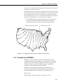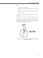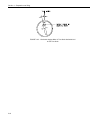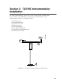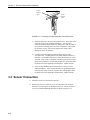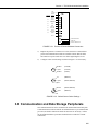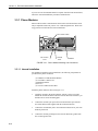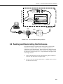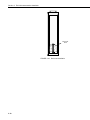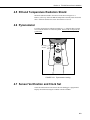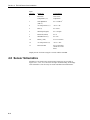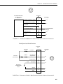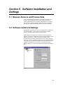
1
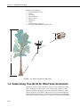
TLX106 WEATHER STATION
INSTRUCTION MANUAL
3/01
COPYRIGHT (c) 1993-2001 CAMPBELL SCIENTIFIC, INC.
This is a blank page.
Warranty and Assistance
The TLX106 WEATHER STATION is warranted by CAMPBELL
SCIENTIFIC, INC. to be free from defects in materials and workmanship
under normal use and service for twelve (12) months from date of shipment
unless specified otherwise. Batteries have no warranty. CAMPBELL
SCIENTIFIC, INC.'s obligation under this warranty is limited to repairing or
replacing (at CAMPBELL SCIENTIFIC, INC.'s option) defective products.
The customer shall assume all costs of removing, reinstalling, and shipping
defective products to CAMPBELL SCIENTIFIC, INC. CAMPBELL
SCIENTIFIC, INC. will return such products by surface carrier prepaid. This
warranty shall not apply to any CAMPBELL SCIENTIFIC, INC. products
which have been subjected to modification, misuse, neglect, accidents of
nature, or shipping damage. This warranty is in lieu of all other warranties,
expressed or implied, including warranties of merchantability or fitness for a
particular purpose. CAMPBELL SCIENTIFIC, INC. is not liable for special,
indirect, incidental, or consequential damages.
Products may not be returned without prior authorization. To obtain a
Returned Materials Authorization (RMA), contact CAMPBELL SCIENTIFIC,
INC., phone (435) 753-2342. After an applications engineer determines the
nature of the problem, an RMA number will be issued. Please write this
number clearly on the outside of the shipping container. CAMPBELL
SCIENTIFIC's shipping address is:
CAMPBELL SCIENTIFIC, INC.
RMA#_____
815 West 1800 North
Logan, Utah 84321-1784
CAMPBELL SCIENTIFIC, INC. does not accept collect calls.
Non-warranty products returned for repair should be accompanied by a
purchase order to cover the repair.
815 W. 1800 N.
Logan, UT 84321-1784
USA
Phone (435) 753-2342
FAX (435) 750-9540
www.campbellsci.com
Campbell Scientific Canada Corp.
11564 -149th Street
Edmonton, Alberta T5M 1W7
CANADA
Phone (780) 454-2505
FAX (780) 454-2655
Campbell Scientific Ltd.
Campbell Park
80 Hathern Road
Shepshed, Loughborough
LE12 9GX, U.K.
Phone +44 (0) 1509 601141
FAX +44 (0) 1509 601091
This is a blank page.
TLX106 Weather Station
Table of Contents
1. Preparation and Siting
1.1 Installation Tasks .................................................................................. 1-1
1.1.1 Indoors......................................................................................... 1-1
1.1.2 Outdoors ...................................................................................... 1-1
1.2 Tools Required ...................................................................................... 1-1
1.2.1 Tools for Tower Installation........................................................ 1-2
1.2.2 Tools for Instrumentation and Maintenance................................ 1-2
1.2.3 Supplies for Power and Communications Options...................... 1-3
1.3 Siting and Exposure .............................................................................. 1-3
1.3.1 Wind Speed and Direction .......................................................... 1-3
1.3.2 Temperature and Relative Humidity ........................................... 1-3
1.4 Determining True North for Wind Vane Orientation............................ 1-4
1.4.1 Prompts from GEOMAG ............................................................ 1-5
2. TLX106 Tower Installation
2.1 Base Installation .................................................................................... 2-2
2.1.1 Supplied Components.................................................................. 2-2
2.2.2 Installation ................................................................................... 2-2
2.2 Tower Installation ................................................................................. 2-3
2.2.1 Supplied Components.................................................................. 2-3
2.2.2 Installation ................................................................................... 2-3
2.3 Tower Grounding.................................................................................. 2-4
2.3.1 Supplied Components.................................................................. 2-4
2.3.2 Grounding Procedure .................................................................. 2-5
3. TLX106 Instrumentation Installation
3.1 Enclosure, Datalogger, Power Supply................................................... 3-2
3.1.1 Battery Option Installation .......................................................... 3-2
3.1.2 Solar Panel Installation................................................................ 3-2
3.1.3 AC Power Installation ................................................................. 3-3
3.1.4 Enclosure Installation .................................................................. 3-3
3.2 Sensor Connection ................................................................................ 3-4
3.3 Communication and Data Storage Peripherals...................................... 3-5
3.3.1 Phone Modems............................................................................ 3-6
3.3.2 Short-Haul Modem...................................................................... 3-7
3.4 Sealing and Desiccating the Enclosure ................................................. 3-9
4. TLX106 Sensor Arm Installation
4.1
4.2
4.3
4.4
4.5
Components .......................................................................................... 4-1
Installation............................................................................................. 4-1
Sensor Connection ................................................................................ 4-2
034A Wind Sensor Installation ............................................................. 4-2
RH and Temperature Radiation Shield ................................................. 4-3
i
TLX106 Weather Station Table of Contents
4.6 Pyranometer ..........................................................................................4-3
4.7 Sensor Verification and Clock Set.........................................................4-3
4.8 Sensor Schematics .................................................................................4-4
5. Software Installation and Settings
5.1 Measure Sensors and Process Data .......................................................5-1
5.2 Software Install and Settings .................................................................5-1
5.3 Create Message......................................................................................5-7
6. Maintenance and Troubleshooting
6.1 Maintenance ..........................................................................................6-1
6.1.1 Instrumentation Maintenance ......................................................6-1
6.1.2 Batteries .......................................................................................6-1
6.1.3 Desiccant .....................................................................................6-1
6.1.4 Sensor Maintenance.....................................................................6-2
6.2 Troubleshooting ....................................................................................6-3
6.2.1 No Response Using the Keypad ..................................................6-3
6.2.2 No Response from Datalogger through SC32A or
Modem Peripheral..................................................................6-3
6.2.3 -99999 Displayed in an Input Location .......................................6-4
6.2.4 Unreasonable Results Displayed in an Input Location ................6-4
Figures
1.3-1. Effect of Structure on Wind Flow.....................................................1-4
1.4-1 Magnetic Declination for the Contiguous United States....................1-5
1.4-2 Declination Angles East of True North Are Subtracted from
0 to Get True North .......................................................................1-7
1.4-3 Declination Angles West of True North Are Added to 0
to Get True North ..........................................................................1-8
2.1-1 TLX106 Tower Installation................................................................2-1
2.1-2 TLX106 Tower Base Installation.......................................................2-3
2.2-1 Raising and Grounding the TLX106 Tower ......................................2-4
3-1 TLX106 Instrumentation Mounted on the ET Tower ...........................3-1
3.1-1 Rechargeable Power Mounting Connections .....................................3-2
3.1-2 Solar Panel Mounting.........................................................................3-2
3.1-3 Mounting and Grounding the TLX106 Enclosure .............................3-4
3.2-1 Position of Sensor Bulkhead Connectors ...........................................3-5
3.3-1 Phone Modem Mounting and Connections........................................3-6
3.3-2 Short-Haul Modem Mounting and Connection..................................3-7
3.3-3 Short-Haul Modem Wiring Diagram .................................................3-9
3.4-1 Desiccant Installation .......................................................................3-10
4.2-1 TLX106 Sensor Arm Mounting .........................................................4-1
4.4-1 Wind and RH/Temperature Sensor Installation .................................4-2
4.6-1 Pyranometer Leveling ........................................................................4-3
4.8-1 Schematic of HMP45C-LC RH Temperature Probe and
Connector #1 .................................................................................4-5
4.8-2 Schematic of 034A-LC Wind Speed and Direction Probe and
Connector #2 .................................................................................4-5
4.8-3 Schematic of LI200X-LC Solar Radiation Sensor and
Connector #3 .................................................................................4-6
4.8-4 Schematic of TE525-LC Rain Sensor and Connector #5...................4-6
ii
TLX106 Weather Station Table of Contents
5.3-1 ProLine software provides an easy-to-use message editor ................ 5-7
5.3-2 The available options provided by the source menu are shown ........ 5-8
5.3-3 When the weather station source has been chosen, several
meteorological conditions reported in various units are
provided under the field menu ...................................................... 5-8
iii
This is a blank page.
Section 1. Preparation and Siting
These guidelines apply to several Campbell Scientific weather stations.
1.1 Installation tasks
1.1.1 Indoors
•
Immediately upon receipt of your shipment…
⇒ Open shipping cartons.
⇒ Check contents against invoice. Contact CSI immediately about any
shortages.
•
Several days prior to the planned installation date…
⇒ Collect tools and site information (Section 1)
⇒ Trial run the tower, assembling as much as possible (Section 2)
⇒ Repackage equipment for transport to the field site
1.1.2 Outdoors
•
Locate suitable site (Section 1)
•
Prepare tower (Section 2)
•
TLX106 Stations:
⇒ Place instrumentation enclosure low on the TLX106 Tower (Section
3)
⇒ Install sensor option (Section 4)
⇒ Slide enclosure to top of tower and secure with correct orientation
(Section 3)
1.2 Tools Required
Tools required to install and maintain a weather station are listed below.
1-1
Section 1. Preparation and Siting
1.2.1 Tools for Tower Installation
All Towers
Shovel
Rake
Open end wrenches: 3/8", 7/16", ½", (2) 9/16"
Magnetic compass
6' Step ladder
TLX106 Tower
Tape measure (12’ to 20’)
Claw hammer
Level (24” to 36” )
Hand saw
Materials for concrete form:
(4) 1" x 2" x 12" stakes
(2) 2" x 4" x 96" lumber
(12) 8p double-head nails
(8) 16p double-head nails
20 ft form wire
½ Yard concrete
Concrete trowel, edger
Electrical Fish tape or 20 feet of small diameter rope
Wheelbarrow
1.2.2 Tools for Instrumentation and Maintenance
All Towers
Lock and key for enclosure
Magnetic declination angle (Section 4)
Magnetic compass
Straight bit screwdrivers (small, medium, large)
Phillips-head screwdrivers (small, medium)
Small diagonal side-cuts
Needle-nose pliers
Wire strippers
Pocket knife
Calculator
Volt / Ohm Meter
Electrical Tape
Step ladder (6')
Datalogger prompt sheet
Station manuals
Station log and pen
Open end wrenches: 3/8", 7/16", ½", (2) 9/16"
Socket wrench and 7/16" deep well socket
Adjustable wrench
Pliers
Conduit and associated tools (as required)
Felt-tipped marking pen
Claw hammer
Pipe wrench (12")
1-2
Section 1. Preparation and Siting
1.2.3 Supplies for Power and Communications Options
AC Power
Wire, conduit, and junction boxes as needed
Phone Modem
Hayes compatible calling modem for PC
Phone line to weather station or junction box
Short-Haul Modem
4 Conductor communications cable from PC to weather station or junction box
6' copper ground rod and clamp for PC surge protection (optional)
1.3 Siting and Exposure
CAUTION
If any part of the weather station comes in contact with
power lines, you could be killed. Contact local utilities for
the location of buried utility lines before digging or driving
ground rods.
Selecting an appropriate site for the weather station is critical in order to obtain
accurate meteorological data. In general, the site should be representative of
the general area of interest, and away from the influence of obstructions such
as buildings and trees.
The weather station should not be located where sprinkler irrigation water will
strike sensors or instrument enclosure.
Some general guidelines for site selection are listed below, which were
1
2
3
condensed from EPA (1988) , WMO (1983) , and AASC (1985) publications.
1.3.1 Wind Speed and Direction
Wind sensors should be located over open level terrain, and at a distance of at
least ten times (EPA) the height of any nearby building, tree or other
obstruction, as illustrated in Figure 1.3-1.
1.3.2 Temperature and Relative Humidity
Sensors should be located over an open level area at least 9 m (EPA) in
diameter. The surface should be covered by short grass, or where grass does
not grow, the natural earth surface. Sensors should be located at a distance of
at least four times the height of any nearby obstruction and at least 30 m (EPA)
from large paved areas. Sensors should be protected from thermal radiation,
and adequately ventilated.
1-3
Section 1. Preparation and Siting
Situations to avoid include:
• large industrial heat sources
• rooftops
• steep slopes
• sheltered hollows
• high vegetation
• shaded areas
• swamps
• areas where snow drifts occur
• low places holding standing water after rains
MADE IN USA
eight of tree
ogan Uta
FIGURE 1.3-1. Effect of Structure on Wind Flow
1.4 Determining True North for Wind Vane Orientation
Magnetic declination, or other methods to find True North, should be determined
prior to installing the weather station. True North is usually found by reading a
magnetic compass and applying the correction for magnetic declination*; where
magnetic declination is the number of degrees between True North and Magnetic
North. Magnetic declination for a specific site can be obtained from a USFA map,
local airport, or through a computer service offered by the USFS called GEOMAG
1-4
Section 1. Preparation and Siting
(Section 1.4.1). A general map showing magnetic declination for the contiguous
United States is shown in Figure 1.4-1.
Declination angles east of True North are considered negative, and are subtracted
from 0 degrees to get True North as shown Figure 1.4-2. Declination angles west
of True North are con-sidered positive, and are added to 0 degrees to get True
North as shown in Figure 1.4-3. For example, the declination for Logan, Utah is
16° East. True North is 360° - 16°, or 344° as read on a compass.
*
Other methods employ observations using the North Star or the sun, and
are discussed in the Quality Assurance Handbook for Air Pollution
Measurement Systems, Volume IV - Meteorological Measurements4.
Subtract declination from 360°
Add declination to 0°
FIGURE 1.4-1. Magnetic Declination for the Contiguous United States
1.4.1 Prompts from GEOMAG
GEOMAG is accessed by phone with a PC and telephone modem, and a
communications program such as GraphTerm (PC208 Software). GEOMAG
prompts the caller for site latitude, longitude, and elevation, which it uses to
determine the magnetic declination and annual change. The following
information, menu, and prompts are from GEOMAG:
GEOMAG is a user-friendly program that provides estimates of the
geomagnetic field elements, including declination and total field intensity,
based upon Magnetic Models. The program is accessible by modem.
Modem Access:
Modem settings: No parity, 8 data bits, and 1 stop bit (i.e., N81)
1-5
Section 1. Preparation and Siting
Telephone numbers:
Phone Number
Baud Rates
303-273-8672
303-273-8673
303-273-8678
2400
1200
1200
Upon carrier-signal detection, press Return once or twice.
If you are using one of the commercial numbers, the following prompts will
appear. Type the responses shown (followed by pressing RETURN):
GLDSV1>
Username:
c neis
QED
[RETURN]
[RETURN]
MAIN MENU
Type
Q
L
M
X
for Quick Epicenter Determinations (QED)
for Earthquake Lists (EQLIST)
for Geomagnetic Field Values (GEOMAG)
to log out
Enter program option: M
Would you like information on how to run GEOMAG (Y/N)? N
Options:
1 = Field Values (D, I, H, X, Z, F)
2 = Magnetic Pole Positions
3 = Dipole Axis and Magnitude
4 = Magnetic Center
[1] : 1
Display values twice
Name of field model
Date
Latitude
Longitude
Elevation
[N]: press return
[USCON90]: press return
[current date]: press return
: 42/2 N
: 111/51/2 W
: 4454 ft
Example of report generated by GEOMAG:
Model: USCON90
Date : 7/27/93
D
deg min
15 59.6
Annual change:
0 -6.1
1-6
Latitude: 42/2 N
Longitude: 111/51/2 W
Elevation: 4454.0 ft
Section 1. Preparation and Siting
Exiting:
Press "Cntrl-Z" to exit GEOMAG.
When the main menu reappears either select another option or type "X" to
log out.
If you used one of the commercial numbers, the GLDSV1> prompt will
reappear.
Type "LO" to disconnect.
Use of GEOMAG is free (except for telephone charges). If possible, please
avoid using
GEOMAG between 9 a.m. and 4 p.m., mountain time, Monday through Friday.
The declination in the example above is listed as 15 degrees and 59.6 minutes.
Expressed in degrees, this would be 15.99 degrees. As shown in Figure 1.4-1,
the declination for Utah is east, so True North for this site is 360 - 15.99, or
344 degrees. The annual change is -6.1 minutes.
FIGURE 1.4-2. Declination Angles East of True North Are Subtracted
From 0 to Get True North
1-7
Section 1. Preparation and Siting
FIGURE 1.4-3. Declination Angles West of True North Are Added to 0
to Get True North
1-8
Section 2. TLX106 Tower Installation
DANGER
Do not install near power lines. If any part of the tower
comes in contact with power lines you could be
KILLED. Contact local utilities for the location of
buried utility lines before digging or driving grounding
rods.
CAUTION
Do not fit the 3 meter TLX106 Tower sections together until
the appropriate time. Once attached, they cannot be
detached.
The TLX106 Tower provides a support structure for mounting the TLX106
weather station components. Figure 2.1-1 shows a typical TLX106 Tower
installation option. The tower is designed to withstand winds of 100 mph. The
lightning rod assembly is attached after the instrumentation enclosure is
installed (Section 3.1).
Transformer
ser upplied
unction o
16
ower
T Tower
ale o
110
round
od
ommunications
Line
Direct ury
plices
oncrete
ase
FIGURE 2.1-1. TLX106 Tower Installation
2-1
Section 2. TLX106 Tower Installation
2.1 Base Installation
2.1.1 Supplied Components
(3) ½ inch L-Bolts
(9) ½ inch Nuts
(1) Anchor Template
Refer to Section 1 for components supplied by installer.
2.1.2 Installation
2-2
1.
The TLX106 Tower attaches to a user supplied concrete foundation
constructed as shown in Figure 2.1-2.
2.
Construct the concrete form with 2" x 4" lumber and 16p nails.
3.
Assemble the template and anchor bolts. There should be two nuts below
and one nut above the template on each bolt.
4.
Clear an area large enough to set the form at the desired elevation.
5.
Dig a hole 2 feet x 2 feet x 2 feet. Lighter soils may require a deeper
hole. About 20 inches below the top of the hole, gouge a small cavity in
one wall of the hole. The cavity should be about 4 inches deep and just
large enough in diameter to insert one end of the conduit. Make certain
the cavity "points" in the direction from which power and
communications cables will come.
6.
Center the form over the hole. Adjacent to the form, drive four stakes
into the soil. Secure the leveled form to the stakes with the 8p nails.
7.
Cap the ends of the conduit with duct tape. Position the conduit and wire
into place by securing the wire to nails in the form.
8.
Fill the hole and form with approximately ½ yard of concrete. Screed the
concrete level with the top of the form. Center the template assembly
over the conduit and press into the concrete. Put 2 x 4 spacers between
the template and the top of the form. The bottom of the bolt threads
should be about ½ inch above the concrete. The template must be level in
two dimensions. Use a trowel and edger to finish.
9.
Wait 24 hours before removing the concrete form. Wait 7 days before
mounting the TLX106 Tower.
Section 2. TLX106 Tower Installation
D
O
TO
O
OT
O OLT
LL
T
TD
O
TLT
FIGURE 2.1-2. TLX106 Tower Base Installation
2.2 Tower Installation
2.2.1 Supplied Components
(1) Upper Tower Section (Tapered)
(1) Lower Tower Section
(6) ½ inch Washers
(1) 12 foot 12 AWG Ground Cable
(1) Tower Cap
(1) 20' communications cable
(1) 20' power cable
Refer to Section 1 for components supplied by installer.
2.2.2 Installation
Attach the tower to the base as shown in Figure 2.2-1.
1.
Dig a hole close to the concrete base to access the lower conduit opening.
From the hole, trench to the power and communications sources. Remove
the duct tape from both ends of the conduit.
2.
Remove the template. Attach the two pieces of the tower. This is a
permanent connection and cannot be undone. Lay the tower on the
ground with the base next to the concrete foundation.
3.
Thread communications and power cables through the tower and conduit.
Electrical fish tape will help.
2-3
Section 2. TLX106 Tower Installation
4.
Cut and save a 9 inch piece of 12 AWG ground wire from the 12 foot
length provided. Thread the remaining 11 foot ground wire through the
tower. Secure all wiring so it does not slip back into the tower or conduit.
5.
Place the tower cap over the tower end.
6.
Raise the tower on a still day. Place a washer on top of the two nuts on
each foundation bolt. Taking great care not to damage cables between the
tower and conduit, raise the tower and lower it onto the conduit and
mounting bolts. Install a washer and nut on each bolt and hand tighten.
Check plumb of the tower by placing a level on the north and east sides of
the lower tower section. Adjust the topmost of the two lower nuts
(leveling nut) on each bolt as necessary. When plumb is established, lock
the leveling nut in place by tightening the lowest nut against it. Tighten
the three top nuts with the wrench.
12AWG Wire
4AWG Cable
FIGURE 2.2-1. Raising and Grounding the TLX106 Tower
2.3 Tower Grounding
2.3.1 Supplied Components
(1) 5 foot 4 AWG Ground Cable
(1) Copper Ground Lug, Bolt
(1) Ground Rod, Clamp
Refer to Section 1 for components supplied by installer.
2-4
Section 2. TLX106 Tower Installation
2.3.2 Grounding Procedure
Ground the tower as shown in Figure 2.2-1.
1.
Place the ground rod clamp on the rod. Secure it about 3 inches from the
top. Do this before the rod is driven into the ground. Be careful not to
damage the clamp with the hammer
2.
Taking care not to damage power or communications lines, drive the
ground rod close to the foundation using a fence post driver or sledge
hammer. Drive the rod at an angle if an impenetrable hardpan layer
exists. Soften hard clay soils with water if necessary.
3.
Strip 1 inch of insulation from both ends of the 4 AWG ground cable.
Strip 1 inch of insulation from the lower end of the 14 AWG ground wire.
Install the tower grounding lug to the tower base with the 7/16 bolt
provided (Figure 2.2-1). Loosen the lug's set screw and insert the 4 AWG
and 14 AWG wire. Tighten the set screw.
4.
Loosen the ground rod clamp. Insert the 4 AWG wire. Tighten the clamp
(Figure 2.2-1).
2-5
This is a blank page.
Section 3. TLX106 Instrumentation
Installation
The weather station datalogger, power supply, sensor connection panel, communications
devices, and data retrieval peripherals are mounted in the TLX106 enclosure at the
locations shown in Figure 3-1. Components include:
(1) TLX106 Enclosure
(1) 4 unit Desiccant Pack
(1) Flat Point Screw Driver
(1) Philips Screwdriver
(1) Power Supply Option
(1) Telecommunications Option
(1) 9 inch piece of 12 AWG ground wire
(1) Lightning rod and clamp
TLX106
FIGURE 3-1. TLX106 Instrumentation Mounted on the ET Tower
3-1
Section 3. TLX106 Instrumentation Installation
3.1 Enclosure, Datalogger, Power Supply
3.1.1 Battery Option Installation
Solar Panel or 16 VAC
Power Cable
S
FIGURE 3.1-1. Rechargeable Power Mounting and Connections
a)
NOTE
Sealed Rechargeable Battery Option: Install the kit as shown in Figure
3.1-1. An unregulated solar panel or 17 to 24 VAC must be used with the
rechargeable battery at all times. In either case, power is routed through
the Heyco fitting on the enclosure back and connected to the CHG ports
by depressing connector levers. Polarity of the CHG connection does not
matter. Install the rechargeable battery and plug the battery lead into the
connector labeled “ LA” .
Press the connector levers gently or they might break.
3.1.2 Solar Panel Installation
FIGURE 3.1-2. Solar Panel Mounting
a)
3-2
Mount the solar panel to the tower using the mounting brackets as shown
in Figure 3.1-2. Mount the solar panel to the tower so it faces south
(northern hemisphere). Position it as high off the ground as practical,
ensuring it cannot interfere with air flow or sunlight around the sensors.
Section 3. TLX106 Instrumentation Installation
The solar panel should be oriented to receive maximum insolation over
the course of the year. Suggested tilt angles (referenced to the horizontal
plane) are listed below.
b)
Site Latitude
Tilt Angle
0 to 10 degrees
10 degrees
11 to 20
Latitude + 5 degrees
21 to 45
Latitude + 10 degrees
46 to 65
Latitude + 15 degrees
>65
80 degrees
After determining the tilt angle, loosen the two bolts that attach the
mounting bracket to the panel. Adjust the angle, then tighten the bolts.
Secure the lead wire to the mast using wire ties. Make electrical
connections as described in 3.1.1a above.
3.1.3 AC Power Installation
a)
The AC power option includes a 120 VAC to 16 VAC. The transformer
should be mounted inside a user supplied junction box according to local
electrical codes. Dangerous electrical accidents may be avoided by
locating the transformer remotely and burying a low voltage line to the
station. The low voltage will carry up to 500 feet on an 18 AWG power
cable.
b)
Shut off 110 VAC power at the main breaker. Connect the primary leads
of the transformer to 110 VAC following instructions provided with the
transformer. Connect a two conductor cable to the secondary terminals of
the transformer. Route the cable from the transformer to the TLX106
Enclosure according to local electrical codes.
3.1.4 Enclosure Installation
1.
Mount and ground the TLX106 enclosure on the TLX106 Tower as
shown in Figure 3.1-3.
a)
Place the enclosure low on the tower. Do not tighten clamps.
b) Install the sensor arm (TLX106) as described in Section 4.
3-3
Section 3. TLX106 Instrumentation Installation
9-inch
Ground
Wire
ORT
H
Tower
Ground
Wire
FIGURE 3.1-3. Mounting and Grounding the TLX106 Enclosure
c)
Slide the enclosure to the top of the TLX106 tower. Position it on the
north side of the tower (northern hemisphere). The top of the
enclosure should be flush with the top of the tower, with the width of
the sensor arm extending above the tower. Tighten the clamps until
the enclosure is snug. Do not over-tighten since doing so may
damage the tower or enclosure.
d) Carefully mount the lightning rod and clamp to the top of the
TLX106 Tower. Clearance between the clamp and the enclosure is
minimal. Care should be taken not to scratch the enclosure or sensor
assembly. Strip 1 inch of insulation from the top end of the 12 AWG
green tower ground wire, curl the end and place the curled end under
the head of one of the lightning rod clamp bolts. Tighten the bolt.
e)
Strip 1 inch of insulation from each end of the 9 inch piece of 12
AWG ground wire. Insert one end into the brass ground lug located
at the top back of the enclosure. Curl the other end and place under
the head of one of the lightning rod clamp bolts. Tighten the bolt.
3.2 Sensor Connection
3-4
1)
Install the sensor set as described in Section 4.
2)
Remove the protective connector cover from the back of the TLX106
Enclosure by removing the two phillips head screws. Sensors connect to
one of seven labeled bulkhead connectors as shown in Figure 3.2-1.
Section 3. TLX106 Instrumentation Installation
Earth
Ground
Stand off
Connector
Sensors
#4
TEMP
CS615
#2
WS/WD
#6
SDI 12
GYP BLOCK
#7
TEMP
#5
RAIN
(PRECIP)
#1
TEMP / RH
#3
SOLAR
RADIATION
#8
COMM
CS I/O
POWER CABLE PORT
STAND OFF
COAXIAL CONNECTION
FIGURE 3.2-1. Position of Sensor Bulkhead Connectors
3)
Replace the protective connector cover after sensors are connected and
power and communications cables are installed. Ensure that all cables
and connector caps are under the cover before tightening the screws.
4)
Configure sensor switch settings as shown in Figure 3.2-2 if necessary.
604 Ohm
(LI190SB)
Open
(LI1200X)
100 Ohm
(LI200S)
1K
(HMP35C)
Open
(CS500, HMP45C)
Open
SW 12V
Open
(CS500, HMP45C)
(HMP35C)
5V
FIGURE 3.2-2. Default Sensor Switch Settings
3.3 Communication and Data Storage Peripherals
One communications kit can be mounted to the TLX106 Enclosure back plate.
Communication kits ordered with the TLX106 Enclosure are pre-mounted and
pre-wired; no further connections inside the enclosure are necessary. Follow
the "External Installation" procedures outlined below to make the external
connections.
3-5
Section 3. TLX106 Instrumentation Installation
If you received a telecommunications kit separate from the TLX106 Enclosure,
follow the "Internal Installation" procedures outlined below.
3.3.1 Phone Modems
Phone modems enable communications between the TLX106 Enclosure and a
Hayes compatible modem in your PC over a dedicated phone line. Phone line
surge protection in built into the TLX106 Enclosure.
P/N 10588 Cable
RJ11 Patch
Cord
Ground
Wire
Modem
FIGURE 3.3-1. Phone Modem Mounting and Connections
3.3.1.1 Internal Installation
For installation inside the TLX106 Enclosure, the following components are
provided in the phone modem kit:
(1) COM200 or COM300 Phone Modem
(1) 12 inch RJ-11 Patch Cord
(1) Mounting Bracket
(4) Screws
(1) 12 inch 14 AWG Ground Wire
Install the phone modem as shown in Figure 3.3-1.
3-6
1.
Attach the modem to the modem bracket with the 4 screws provided.
Mount the modem and bracket into the TLX106 Enclosure with the 3 prethreaded screws on the mounting plate.
2.
Connect the modem 9-pin port to the TLX106 Enclosure port with the
P/N 10588 ribbon cable supplied with the TLX106 Enclosure.
3.
Connect the modem RJ-ll jack to the TLX106 Enclosure RJ-11 jack with
the RJ-ll patch cord.
4.
Connect the modem ground port to the TLX106 Enclosure ground with
the 14 AWG ground wire.
Section 3. TLX106 Instrumentation Installation
3.3.1.2 External Installation
The following modem kit components are used to make the external
connections:
(1) Direct Burial Splice Kit
(1) 20 foot Telephone Patch Cord with Connector
1)
Connect the 20 foot patch cord to the connector marked "comm" on the
external back panel, under the protective cover.
2)
Splice the labeled "Tip" and "Ring" lines of the patch cord to the
telephone service line. Use the direct burial splice kit when splices are in
a valve box or buried.
3.3.2 Short-Haul Modem
CAMPBE
SCIENTIIC TD
SC32 - SN E155
C
Short-haul modems enable communication between a datalogger and computer
over two twisted pairs of wires. The maximum distance between modems is
determined by baud rate and wire gauge. At 9600 baud, the approximate range
is 4.0 miles. DCE / DTE switches on the modems are set to DCE.
FIGURE 3.3-2. Short-Haul Modem Mounting and Connection
3.3.2.1 Internal Installation
For installation inside the TLX106 Enclosure, the following components are
provided in the short-haul modem kit:
(1) SC932C Interface
(1) Rad Modem
(1) Rad/SC932C Mounting Bracket
(4) Screws
(1) 12 inch 4-wire patch cable
Install the short-haul modems as shown in Figure 3.3-2 and 3.3-3.
1.
Mount the Rad / SC932C mounting bracket into the TLX106 Enclosure
with the 3 pre-threaded screws provided.
2.
Connect the Rad Modem and SC932C. Strap them into the mounting
bracket under the Velcro strap.
3-7
Section 3. TLX106 Instrumentation Installation
3.
Connect the SC932C 9-pin port to the internal TLX106 Enclosure 9-pin
port with the blue ribbon cable provided.
4.
Wire the Rad Modem to the TLX106 Enclosure with the 12 inch patch
cord. Match wire labels to wiring panel labels on both the TLX106
Enclosure and the Rad Modem (+XMT to +XMT, etc.). A small screw
driver in provided with the TLX106 Enclosure to access the Rad Modem
connections.
3.3.2.2 External Installation
The following short-haul kit components are used to make the external
connections:
At the TLX106 Enclosure:
(1) 20 foot 4-Wire Patch Cable
(2) 2 Direct Burial Splice Kits
(1) Length of User Supplied Wire (Supplier: Anixter, p/n F-02P22BPN,
Phone 847-677-2600)
At the PC:
(1) Rad Modem
(1) 5 foot 4-wire Patch Cable
(1) 10 foot 14 AWG Ground Wire
(1) Surge Protector and Case
3-8
1)
Connect the 20 foot patch cable to the connector marked "comm" on the
external back panel of the TLX106 Enclosure. Splice this cable to the
user supplied cable, using the direct burial splice kits.
2)
Mount the surge protector to a flat surface near the PC's serial port.
Ground the center terminal to an earth (or building) ground using the 14
AWG wire.
3)
Connect the 5 foot patch cord to the Rad Modem. Fasten the cable to the
strain relief tab with a cable tie. Connect the Rad to the PC's serial port
either directly (25 pin port) or through a 9 to 25 pin serial converter.
4)
Route the user-supplied cable from the remote splice to the surge
protector. Connect it and the 5 foot patch cord to the surge protector.
Section 3. TLX106 Instrumentation Installation
- RCV (white)
TLX106 ENCLOSURE
ET106 ENCLOSURE
- XMT (black)
EBPMAC
DT CIITNEICS
551E NS - 239CS
TLX106
ET106 ENCLOSURE
ENCLOSURE
C
+ RCV (green)
+ XMT (red)
+ RCV (red)
- RCV (black)
+ XMT (green)
- XMT (white)
To # 8
External Connector
Surge
Protector
PC
SRM-5A
1
+ RCV (red)
- RCV (black)
2
User
Supplied
Cable
Splices
1
+ RCV
RED
2
- RCV
BLACK
+ XMT (green)
3
- XMT (white)
3
4
4
+ XMT
GREEN
- XMT
WHITE
Earth Ground
FIGURE 3.3-3. Short-Haul Modem Wiring Diagram
3.4 Sealing and Desiccating the Enclosure
The TLX106 Enclosure is supplied with a desiccant pack. The desiccant
maintains a low humidity in the enclosure to minimize the chance of
condensation on the instrumentation. Desiccant should be changed when the
internal TLX106 Enclosure humidity sensor measures 30% or higher. Install
the desiccant as shown in Figure 3.4-1. Keep unused desiccant tightly sealed
in an airtight container.
1)
Take the desiccant pack out of its sealed plastic bag. Place it under the
desiccant strap just before leaving the station.
2)
Be sure to close the enclosure hasp securely. A padlock may be used on
the latch for extra security.
3-9
Section 3. TLX106 Instrumentation Installation
Desiccant
Pack
DO NOT EAT
UNITED DESICCAN
101CHRISTINE, BELEN,
TS-GATES
NEW MEXICO 87002
DESI PAK
SPECIFICATION MIL-D-3464
TYPE I &II
REACTIVATION TIME
IN-BAG 16 HOURS
AT 250 O F
DESICCANT
CONTENTS
PACKAGE USE
ACTIVATED
4
AND STATIC
BAGGED FOR
UNITS
DEHUMIDIFICATION
DO NOT EAT
UNITED DESICCAN
101CHRISTINE, BELEN,
TS-GATES
NEW MEXICO 87002
DESI PAK
SPECIFICATION MIL-D-3464
TYPE I &II
REACTIVATION TIME
IN-BAG 16 HOURS
AT 250O F
DESICCANT
CONTENTS
PACKAGE USE
ACTIVATED
4
AND STATIC
BAGGED FOR
UNITS
DEHUMIDIFICATION
FIGURE 3.4-1. Desiccant Installation
3-10
Section 4. TLX106 Sensor Arm
Installation
4.1 Components
(1) TLX106 Sensor Arm
(1) Met One 034A Wind Sensor
(1) 034A Mounting Shaft
(1) Radiation Shield
4.2 Installation
Install the TLX106 Sensor Arm after the Enclosure is mounted low on the
Tower. You may need to temporarily remove communications option. Mount
the sensor arm as shown in Figure 4.2-1 without the wind sensor attached.
ET Sensor
Arm
ET Enclosure
Screws
(4)
FIGURE 4.2-1. TLX106 Sensor Arm Mounting
1)
Remove the cover from the Enclosure.
2)
Place the sensor arm on top of the enclosure, lining up the four threaded
holes on the under side of the arm with the four holes in the top of the
enclosure. Attach the arm to the enclosure by inserting and tightening
four Phillips head screws. Adjust the position of the Enclosure so that the
sensor arm is oriented along a due east to due west axis.
4-1
Section 4. TLX106 Sensor Arm Installation
4.3 Sensor Connection
Refer to Section 3 for sensor connection details.
4.4 034A Wind Sensor Installation
Install the 034A Wind Sensor as shown in Figure 4.4-1 after the sensor arm is
securely installed. The wind vane is oriented after the datalogger has been
programmed, and the location of True North has been determined (Section
1.2). Orientation is most easily done with two people, one to aim and adjust
the sensor, while the other observes the wind direction displayed by CR10KD
Keyboard Display or a laptop PC.
FIGURE 4.4-1. Wind and RH/Temperature Sensor Installation
4-2
1)
Place the 034A in the 034A Mounting Shaft pointing the vane due south.
Tighten the alignment screw.
2)
Attach the 034A and mounting shaft to the sensor arm. Insert the
mounting shaft into the U-bolt clamp. Adjust sensor height to 2 or 3
meters by moving the mounting shaft up or down in the clamp. Lightly
tighten clamp nuts.
3)
Attach the 034A connector to the 034A.
4)
Establish a reference point on the horizon for True North.
5)
Sighting down the instrument center line, aim the counter weight at True
North.
6)
While holding the wind vane position, slowly rotate the sensor base until
the sensor is aligned properly. Securely tighten the clamp nuts.
Section 4. TLX106 Sensor Arm Installation
4.5 RH and Temperature Radiation Shield
Mount the radiation shield to the sensor arm as shown in Figure 4.4-1.
Remove yellow cap. Place the RH and temperature assembly inside the shield
shaft. Attach the shield to the sensor arm with the two screws.
4.6 Pyranometer
Level the pyranometer as indicated in Figure 4.6-1. Adjust the three leveling
screws until the bubble level indicates plumb. Remove the red cap from the
pyranometer.
Leveling
Screws
FIGURE 4.6-1. Pyranometer Leveling
4.7 Sensor Verification and Clock Set
Check the measurements of all sensors after the datalogger is programmed.
Display measurements using the *6 Mode with the CR10KD.
4-3
Section 4. TLX106 Sensor Arm Installation
Input
Location
Parameter
Normal Range
1
Enclosure
Temperature (°C)
Close to air
temperature
3
Solar Radiation
-2
(kW m )
0 to 1.2 kW m
4
Air Temperature (°C)
-40° to +50°
5
RH (%)
0 to 100%
6
Wind Speed (mph)
0 to 110 mph
7
Rain Fall (inches)
0 to .2
8
Wind Direction (°)
0 to 359
10
Battery (Volt)
9.6 to 14.0 Volts
12
Air Temperature (°F)
-40° to +122°
13
Enclosure RH
0% to 30% when
sealed for several
hours
-2
Display and set clock time using the *5 mode with the CR10KD.
4.8 Sensor Schematics
Schematics of TLX106 sensors and associated connectors are provided in
Figures 4.8-1, 4.8-2, 4.8-3, and 4.8-4 for help in troubleshooting. Knowledge
of the schematics is not necessary for routine installation and maintenance.
4-4
Section 4. TLX106 Sensor Arm Installation
3
4
2
6
5
1
Connector
Pin
Air Temperature and
Relative Humidity
Sensor
Relative Humidity (0-1VDC)
1
Air Temperature (0-1VDC)
2
Not Used
3
12V Switched Supply
4
Analog Ground
5
Shield
6
Datalogger
1H
1L
12VDC Switched
Supply
AG
G
FIGURE 4.8-1. Schematic of HMP45C-LC RH and Temperature Probe and Connector #1
Wind Speed and Wind Direction
Connector
Pin
10K OHM
1K OHM
10K OHM
Potentiometer
Excitation
1
Wind Direction
Signal Return
2
Datalogger
E2
2H
3
4
2
6
Pulse
Analog Ground
4
Wind Speed
3
Magnetically
Activated Reed
Switch
Ground
Shield
1
5
AG
P1
5
G
6
G
FIGURE 4.8-2. Schematic of 034A-LC Wind Speed and Direction Probe and Connector #2
4-5
Section 4. TLX106 Sensor Arm Installation
3
4
2
6
1
5
Connector
Pin
Solar Radiation
Sensor
Datalogger
1
3H
40.2 - 90.2 OHM
2
3L
Not Used
3
Not Used
4
Not Used
5
6
Shield
G
FIGURE 4.8-3. Schematic of LI200X-LC Solar Radiation Sensor and Connector #3
Connector
Pin
Tipping Rain Bucket
Not Used
1
3
4
2
6
Not Used
2
Not Used
4
Pulse
3
Ground
5
1
5
Datalogger
Magnetically
Activated Reed
Switch
Shield
P2
G
6
G
FIGURE 4.8-4. Schematic of TE525-LC Rain Sensor and Connector #5
4-6
Section 5. Software Installation and
Settings
5.1 Measure Sensors and Process Data
A pre-written datalogger program (PN 14079) comes installed in the
TLX106. This program sets the scan rate, measures the sensors,
processes internally and stores the data. This program will be factory
corrected for the station’s latitude, longitude, elevation, and standard
time meridian, and then downloaded to the station before shipping.
5.2 Software Install and Settings
Install Proline and make sure to select the Weather Source install using
the install procedure. The user must have purchased the Weather
Source as an option to their ProLine software package.
Install LoggerNet according to the manual (refer to the LoggerNet
manual). Set up the communication link to the logger with the Network
Editor as shown below. (This is for the phone modem with AC
powered station; other setup combinations may vary slightly, but they
will be very similar.) Start the LoggerNet server by clicking on the blue
icon. Make sure Communications Enabled is checked and the proper
Com Port Connection is selected. Enter 10 seconds in the Extra
Response Time box. Click on the Apply button and proceed to the next
step.
5-1
Section 5. Software Installation and Settings
Here again the Communications Enabled button must be selected. Then
select the proper Modem Type and zero out the Extra Response Time.
Then press Apply and continue to the next step.
Here again the Communications Enabled must be selected. Then add
the appropriate Phone Number. Then zero out the Maximum Time On
Line box. This will make the maximum time on line indefinite. Leave
the Packet Size and Extra Response Time at default. Then press Apply
and continue to the next step.
5-2
Section 5. Software Installation and Settings
The final termination must be to a CR10X-TD logger. The Proline will
default to work with a logger named ‘lgr1’, but you can change this
default if you want to name your logger something else. Change the
logger name here and then refer to the RDE extra settings to make sure
you change the name there so that the RDE will be able to find the
logger with the appropriate data. Then zero out the Maximum Time On
Line, leave the Packet Size and Extra Response Time at default. Set
your Security Code options. They may be left at the default if desired.
Here the user will normally want to select a Collection Interval of 1
second, a Primary Retry Interval of 10 seconds, a Number of Primary
Retries at 3, and a Secondary Retry Interval of 2 minutes. Longer times
may be entered, but this may effect the RDE settings if the collection
interval is longer than 1 or 2 minutes. If your Collection Interval is set
higher to conserve power, you will want to hang up and redial, as the
phone modem in the weather station is the major power consumer (140
ma active and .12 ma when inactive). For the station to hang up, the
“ Keep Logger On Line” box must be deselected in the extra settings of
the RDE mentioned later in this manual. For now, do not enable data
collection by selecting the “ Scheduled Collection Enable” box until
after you set up the extra settings in the RDE. For now, press the Apply
button, close the Network Editor, and continue.
5-3
Section 5. Software Installation and Settings
If not already started, start the LoggerNet server by double clicking the
blue icon. Then start the Control Panel. It should automatically
connect to the server. Then select the appropriate logger and click on
the Connection bar. The computer should initiate and connect with the
station. Then pull down the Options menu, go to Advanced, and then
select Update Table Definitions. This procedure may take a minute as
the weather station updates LoggerNet. Once it is complete, you may
disconnect and close the Control Panel.
Now open the RDE Manager usually through the Start, Programs,
Proline, Proline Utilities, RDE Manager. All the RDE sources you
purchased and installed should appear. Three of them are related to the
Weather Source. Select the Weather Extremes, Weather Parameters,
and Weather Basics sources. Then click on the Extra Settings button
beside one of the sources. You only need to do this for one of these
three sources because the extra settings is tied to all three. If you
change the extra settings in one, it will change them in all three.
RDE (Extra Settings)
5-4
“ Host”
The IP or Internet address of the computer
that is running LoggerNet is entered here.
In the case shown, LoggerNet is running on
the same computer as the RDE.
“ Port”
This will almost always be 6789. It is an
option that may be used in future versions of
this program. For now just leave it as 6789.
“ User”
Your LoggerNet user name is entered here.
“ Password”
The password you entered in LoggerNet, if
any.
“ Logger Name”
The name of the logger, which is essentially
the weather station, is entered here. Default
is lgr1. The name of the logger is set in Net
Admin of LoggerNet.
Section 5. Software Installation and Settings
“ Keep Logger On Line”
This is used to force LoggerNet to stay
connected to the station the entire time the
LoggerNet server is open. This is desirable
when there are short collection intervals.
The default settings are shown below. The Host is the computer that is
running LoggerNet. This is why the “ LocalHost” is shown in this case
as LoggerNet is running on the same machine as the RDE. The Port
setting will almost always be set to 6789. The User name and Password
are for LoggerNet security. The Logger Name must be the name of the
logger previously set up in the Net Admin. This will allow the
LoggerNet program to communicate with other loggers (not interfaced
with the sign) and allow the user to select the name for the logger that
sign data will come from. The Keep Logger Online check box will
allow the user to force the LoggerNet server to connect to the station
and stay connected. This is desirable when the collection interval in Net
Admin is set to 1 or 2 minute or less. It may be unchecked so that a
slower collection interval may be used. This will decrease the power
consumption of the station in case a solar panel is used. It has proven
useful in AC powered stations as well when AC power is unreliable and
the sign/station administrator will be gone for an extended period of
time (weekend). They can set the collection interval to a longer one and
make it so that the logger will connect every 15 minutes or so. This
way if the power does go out for a couple of days, the modem won’t run
the battery down too low.
Put the LoggerNet server in the startup menu so that it is started each
time the computer is booted. This will cause the station to
automatically re-establish connections with the sign when an auto
reboot is done.
5-5
Section 5. Software Installation and Settings
Now reopen Net Admin and go to the logger previously set up. Now
we will check to see if the Table Definitions have updated correctly by
going to the Data Collection tab. It could look like the following
picture.
Now select the Scheduled Collection tab again. Here you need to
enable the scheduled collection by selecting the Scheduled Collection
Enabled box. Note: if the LoggerNet server is open, it will probably
initiate connection to the station as soon as this is enabled. You can
close the server by right clicking on the blue icon in the lower righthand corner of your screen and selecting Close. It may give you a
warning, just press OK or Yes. Now close Net Admin and you’re ready
to reboot the system so everything will take effect. The LoggerNet
changes take effect almost immediately, but the extra settings in the
RDE always require a reboot before they will take effect.
When your system comes back up, LoggerNet should automatically
start (if you put it in the start up menu) and connect to the weather
station. It may hang up a few times, but after five minutes or so it
should connect and stay connected if the Keep Logger Online button
has been selected in the extra RDE settings. Data is now available for
message creation.
5-6
Section 5. Software Installation and Settings
5.3 Create Message
Perform the following steps using the Message Editor provided in
ProLine Software:
1.
Type the message in the area indicated in Figure 5.3-1.
2.
Move cursor to where you want data inserted.
3.
Select a source from the Source pull-down menu (Figure 5.3-2).
4.
Select the desired field (Figure 5.3-3).
5.
Click on the white cross (Figure 5.3-1) and the data stored in the
selected field will be inserted into the message where the cursor is
located.
Enter the message
that will appear on
the sign here.
The font of the
message and
data are chosen
here.
Source
Pull-Down
Menu
Field
Pull-Down Menu
Click on this to insert the
data into the message.
FIGURE 5.3-1. ProLine software provides an easy-to-use message editor.
5-7
Section 5. Software Installation and Settings
FIGURE 5.3-2. The available options provided by the source menu are shown.
FIGURE 5.3-3. When the weather station source has been chosen, several meteorological
conditions reported in various units are provided under the field menu.
5-8
Section 6. Maintenance and
Troubleshooting
These guidelines apply to several Campbell Scientific weather stations.
6.1 Maintenance
Proper maintenance of weather station components is essential to obtain
accurate data. Equipment must be in good operating condition, which requires
a program of regular inspection and maintenance. Routine and simple
maintenance can be accomplished by the person in charge of the weather
station. More difficult maintenance such as sensor calibration, sensor
performance testing (i.e., bearing torque), and sensor component replacement,
generally requires a skilled technician, or that the instrument be sent to
Campbell Scientific or the manufacturer.
A station log should be maintained for each weather station that includes serial
numbers, dates that the site was visited, and maintenance that was performed.
6.1.1 Instrumentation Maintenance
The instrumentation requires a minimum of routine maintenance. A few
preventative maintenance steps will optimize battery life and decrease the
chances of datalogger failure.
6.1.2 Batteries
Rechargeable power supplies should be connected to an AC transformer or
unregulated solar panel at all times. Be aware of battery voltage that
consistently decreases over time, which indicates a failure in the charging
circuitry.
6.1.3 Desiccant
Enclosure humidity is monitored in the ET Enclosure systems by an RH chip
incorporated into the connector board. Change the desiccant packs when the
enclosure RH exceeds 35%.
Desiccant may be ordered through Campbell Scientific (DSC 20/4) or item
#4905.
Desiccant packs inside of the dataloggers do not require replacement under
normal conditions.
6-1
Section 6. Maintenance and Troubleshooting
6.1.4 Sensor Maintenance
Sensor maintenance should be performed at regular intervals, depending on the
desired accuracy and the conditions of use. A suggested maintenance schedule is
outlined below.
1 week
•
Check the pyranometer for level and contamination. Gently clean, if
needed.
•
Visually inspect the wind sensors and radiation shield.
1 month
•
Check the rain gage funnel for debris and level.
•
Do a visual/audio inspection of the anemometer at low wind speeds.
•
Check the filter of the temperature/humidity sensor for contamination.
General Maintenance
•
An occasional cleaning of the glass on the solar panel will improve its
efficiency.
•
Check sensor leads and cables for cracking, deterioration, proper routing,
and strain relief.
•
Check the tripod or tower for structural damage, proper alignment, and for
level/plumb.
6 months
•
Clean the temperature/humidity sensor.
•
Clean the Gill Radiation Shield.
1 year
•
Replace anemometer bearings.
•
Calibrate the rain gage.
•
Calibrate the HMP45C probe.
2 years
•
Calibrate the pyranometer (some users suggest yearly).
•
Calibrate the HMP45C temperature/humidity sensor.
•
Replace the wind vane potentiometer and bearings.
4 - 5 years
•
Replace sensor cables as required.
Rain Gage Calibration Check
1.
6-2
Secure a metal can that will hold at least one quart of water.
Section 6. Maintenance and Troubleshooting
2.
Punch a very small hole in the bottom of the can.
3.
Place the can in the top funnel of the rain gage and pour 16 fluid ounces
(1 pint) of water into the can. (A 16 oz. soft drink bottle filled to within
2.5 inches of the top may be used for a rough field calibration. An exact
volume will allow for a more precise calibration).
4.
If it takes less than 45 minutes for this water to run out, the hole in the can
is too large.
5.
One hundred tips plus or minus three tips should occur.
6.
Adjusting screws are located on the bottom adjacent to the large center
drain hole. Adjust both screws the same number of turns. Rotation
clockwise increases the number of tips per 16 oz. of water; counter
clockwise rotation decreases the number of tips per 16 oz. of water. One
half turn of both screws causes a 2% to 3% change.
7.
Check and re-level the rain gage lid.
6.2 TroubleShooting
6.2.1 No Response Using the Keypad
Check keypad response after each of the following steps.
A.
Make sure the battery has been installed, and the power switch, if any, is
"ON".
B.
Use a voltmeter to measure the voltage on the 12 V and G terminals; the
voltage must be between 9.6 and 16 VDC.
C.
Disconnect any sensor or peripheral wires connected to the 5 V and 12 V
terminals.
D.
Disconnect any communications or storage peripherals from the
datalogger.
E.
Reset the datalogger by turning the power switch to "OFF", then to "ON"
or disconnect the solar panel or switch off AC power to the station then
disconnect and reconnect the battery. Remember to reconnect the solar
panel or switch on the AC power.
F.
If still no response, call Campbell Scientific.
6.2.2 No Response from Datalogger through SC32A or Modem
Peripheral
At the datalogger:
A.
Make sure the battery has been installed, and the power switch, if any, is
"ON".
B.
Use a voltmeter to measure the voltage on the 12 V and G terminals; the
voltage must be between 9.6 and 16 V DC.
C.
Make sure the datalogger is connected to the modem, and the modem is
properly configured and cabled.
6-3
Section 6. Maintenance and Troubleshooting
At the computer:
D.
Make sure the Station File is configured correctly.
E.
Check the cable(s) between the serial port and the modem. If cables have
not been purchased through Campbell Scientific, check for the following
configuration using an ohm meter:
25-pin serial port:
computer end
modem end
2
3
7
20
2
3
7
20
9-pin serial port:
computer end
modem end
2
3
4
5
3
2
20
7
F.
Make sure the modem is properly configured and cabled (Section 6.6).
G.
If still no response, call Campbell Scientific.
6.2.3 -99999 Displayed in an Input Location
A.
Make sure the battery voltage is between 9.6 and 16 VDC.
B.
With the TLX106, verify that the sensor is connected to the proper
bulkhead connector.
6.2.4 Unreasonable Results Displayed in an Input Location
6-4
A.
Inspect the sensor for damage and/or contamination.
B.
Make sure the sensor is properly wired to the datalogger.
C.
Check the multiplier and offset parameters in the measurement
instruction.