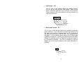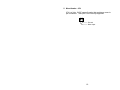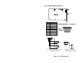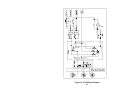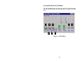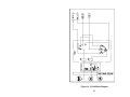
1
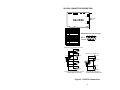
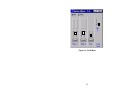
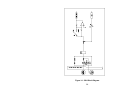
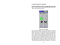
SX-5e SX-6
SX-34 SX-36
Digital Audio Adapter
User's Manual
September 17, 1999
Rev. E
ANTEX ELECTRONICS CORPORATION
th
1125 W. 190 STREET
GARDENA, CALIFORNIA 90248
[email protected]
www.antex.com
Toll Free: 1-800-338-4231
Fax: 310-532-8509
9000-2351-7006
Declaration of Conformity
Standards to which Conformity is Declared:
EN55022 (Class A) 1994, EN 50082-1 1992
This equipment has been verified to comply with the limits for
a class A computing device, pursuant to FCC Rules. In order
to maintain compliance with FCC regulations, shielded cables
must be used with this equipment. Operation with nonapproved equipment or unshielded cables is likely to result in
interference to radio and TV reception. The user is cautioned
that changes and modifications made to the equipment without
the approval of the manufacturer could void the user's authority to operate this equipment.
TABLE OF CONTENTS
INTRODUCTION ...................................................................... 1
CARD INSTALLATION ............................................................. 1
JUMPER SETTINGS & CONNECTIONS ...................... 2
I/O ADDRESSES AND INTERRUPTS .......................... 3
MAKING CONNECTIONS TO THE CARD ............................... 3
SX-35/36 CONNECTOR DESCRIPTION ................................. 5
SX-34 CONNECTOR DESCRIPTION ...................................... 8
SX-6 CONNECTOR DESCRIPTION ........................................ 11
SX-5e CONNECTOR DESCRIPTION ...................................... 13
BALANCED AND UNBALANCED SIGNALS ............................ 13
IMPEDANCE AND SIGNAL LEVELS ....................................... 14
PLAYBACK AND RECORD DEVICES ..................................... 15
COMPRESSION, DATA RATES, AND NETWORKS ............... 16
ISO/MPEG-1 BITRATES .......................................................... 17
DRIVER INSTALLATION.......................................................... 19
WINDOWS 95 .............................................................. 19
Setup Tips (Upgrade Driver, WIN 95) ........................... 19
Setup Tips (Upgrade Driver, WIN 98) ........................... 20
WINDOWS NT.............................................................. 21
ANTEX APPLICATION SOFTWARE INSTALLATION ............. 22
USING WINDOWS DEMONSTRATION SOFTWARE ............. 23
INSTALLING AND USING MULTIPLE CARDS IN A SYSTEM. 27
DUAL DEVICE OPERATION.................................................... 27
MIXER AND BLOCK DIAGRAMS............................................. 28
SX-36 MIXER AND BLOCK DIAGRAM......................... 29
SX-34 MIXER AND BLOCK DIAGRAM......................... 34
SX-6 MIXER AND BLOCK DIAGRAM........................... 36
SX-5e MIXER AND BLOCK DIAGRAM......................... 39
ANTEX METER ........................................................................ 42
TROUBLESHOOTING ............................................................. 46
TECHNICAL/ORDERING INFORMATION: .............................. 49
APPENDIX ............................................................................... 50
Connectors for Male Headers ....................................... 50
Terms ........................................................................... 50
Specifications................................................................ 52
About Digital Audio ....................................................... 54
FIGURES
Figure 1. SX-5e,6,34,35 & SX-36 Jumper Settings................... 2
Figure 2. SX-35/36 Connections.............................................. 5
Figure 3. SX-34 Connections................................................... 8
Figure 4. SX-6 Connections..................................................... 11
Figure 5. Antex Demo Program ............................................... 23
Figure 6. MPEG Bitrates.......................................................... 24
Figure 7. File Open Dialog Box................................................ 25
Figure 8. Auto Repeat ............................................................. 26
Figure 9. SX-36 Mixer.............................................................. 32
Figure 10. SX-36 Block Diagram ............................................. 33
Figure 11. SX-34 Mixer............................................................ 34
Figure 12. SX-34 Block Diagram ............................................. 35
Figure 13. SX-6 Mixer.............................................................. 37
Figure 14. SX-6 Block Diagram ............................................... 38
Figure 15. SX-5e Mixer............................................................ 39
Figure 16. SX-5e Block Diagram ............................................. 41
Figure 18. Antex Meter pull-down menu .................................. 43
Figure 19. Antex Meter options................................................ 44
Figure 20. Analog-to-Digital ..................................................... 56
Figure 21. Digital-to-Analog ..................................................... 57
INTRODUCTION
The Antex SX-5e, SX-6, SX-34 and SX-36 family of cards are ISA
bus audio “add-in” cards for the PC. They all incorporate DSP’s
(Digital Signal Processors), which allow the cards to do a variety
of audio formats. (MPEG, PCM16, MSADPCM, etc.) All cards are
dual device, which means they can operate on 2 hard drive files at
the same time. These cards operate at several fixed standard
sample rates: 8, 11.025, 16, 22.05, 32, 44.1, and 48 KHz. The
SX-5e and SX-6 are playback only cards, and the SX-34 and SX36 have playback and record capability. The SX-5e and SX-34
have unbalanced analog I/O and the SX-6 and SX-36 have balanced analog I/O. Up to 4 cards may be installed into one computer.
Software is provided for Win95/98, and WinNT. Software includes the “driver”, the Antex Demo application, Antex Mixer application, and Antex VU Meter application. Contact Antex Technical Support or visit the Antex website (www.antex.com), for information about DOS or Windows 3.11 drivers, or the Software Developer’s Kit (SDK).
CARD INSTALLATION
Make sure the main power to your computer is OFF. You will
need a 16 bit/AT slot. If you are unfamiliar with the internal design
of your computer see its "Guide to Operations" manual for step by
step installation procedures. To avoid damaging the board or
your computer with static electricity:
1. Touch the metal of your computer chassis first to discharge
the static electricity from yourself before opening the antistatic
bag the Antex Card is packaged in.
2. Move around as little as possible. Don’t shuffle your feet on
carpet or move around in your chair.
3. Handle the card by the bracket and the edges. Try not to
touch the gold fingers or any of the parts on the board.
1
Set the board number with jumpers as shown below. If only one
board is being used, leave the jumpers off (sets to board number
one). When using more than one card in a computer, each board
must be given a different number by setting the jumpers differently on each card. Any model Antex Card may be used with any
other model Antex Card. All model Antex Cards use the same
jumper arrangement to set the board number.
JUMPER SETTINGS & CONNECTIONS
J1
SX-5e/6/34
35/36
Top View
2 4
1 3
Board 1
2 4
1 3
Board 2
2 4
1 3
Board 3
2 4
1 3
Board 4
Covered by jumper
Figure 1. SX-5e,6,34,35 & SX-36 Jumper Settings
The jumpers are oriented vertically so that they may be easily
changed without having to remove the card from the computer
slot if they should need to be changed later. These jumpers only
set the board number, allowing for more than one board in a computer. They do not set interrupts.
2
I/O ADDRESSES AND INTERRUPTS
SX-5e, 6, 34, 35 & 36 I/O addresses and interrupts are software
selectable. The valid I/O addresses are:
180h, 220h, 280h, 300h, 320h and 380h
The valid interrupts are:
2, 3, 4, 5, 10, 11 and 12
Note that interrupts 3 and 4 are normally used by the computer’s
COM ports and will not be available. The interrupt and I/O addresses are selected at the time of software installation or automatically by Windows 95/98.
________________________________________________
MAKING CONNECTIONS TO THE CARD
The more commonly used signals are connected to the card from
the rear of the computer using connectors on the card’s bracket.
Other connectors for auxiliary functions are single or dual row
male headers on the card itself. The pins on these connectors
are numbered as follows:
Dual row headers oriented vertically on the card start with pin 1 in
the upper left corner. Odd number pins continue down the left
column of pins. Even numbers go down the right column of pins,
with pin 2 being at the top.
Single row headers oriented horizontally on the card have pin 1 on
the left.
See the appendix for information on the mating connectors for the
single and dual row headers. Cables which connect to the DB9
connector on the SX-6, SX-35, and SX-36 are available from Antex. The following wiring diagrams are provided to make your own
cables. Antex recommends using shielded twisted pair cable for
3
balanced connections and shielded coax cable for unbalanced
connections. See the section “Balanced and Unbalanced Signals”.
4
SX-35/36 CONNECTOR DESCRIPTION
JP4
JP1
JP7
JP3
JP8
BALANCED
IN/OUT
SX-35/36
JP9
Pin
1
2
3
4
5
6
7
8
Assignment
Ground
Right In Left InRight Out Left Out Right In +
Left In +
Right Out +
9
Left Out +
Balanced Analog I /O Connector
5
4
3 2 1
DB-9
Female
9 8 7 6
Balanced In - XLR male shell, female pins
GND
- 2
1
Left
+ 3
- 2
Unbalanced In - Female RCA
1
Right
5 4 3 2 1
Left
+ 3
9 8 7 6
Right
1
- 2
5 4 3 2 1
Left
9 8 7 6
+ 3
1
Left
- 2
Right
Right
+ 3
Balanced Out - XLR female shell, male pins
SX-35/36 Balanced I/O to XLR
Unbalanced Out - Female RCA
SX-35/36 Unbalanced I/O to RCA
Figure 2. SX-35/36 Connections
5
LINE I/0 (JP8)
Pin
1
Right Line Input +
Pin
3
Right Line Input -
Pin
5
Left Line Input +
Pin
7
Left Line Input -
Pin
9
Right Line Output +
Pin
11
Right Line Output -
Pin
13
Left Line Output +
Pin
15
Left Line Output -
Pin
2,4,6,8,10,12,14,16
Ground
This connector duplicates the function of the DB9 connector. It
might be used with a custom “Industrial Rack Mount PC” with a
special cable harness that brought the connections out to the front
panel.
6
AUX IN (JP9)
Pin
1
Right Aux Input +
Pin
3
Right Aux Input -
Pin
5
Left Aux Input +
Pin
7
Left Aux Input -
Pin
9,11,13,15
No connection
Pin
2,4,6,8,10,12,14,16
Ground
The Auxiliary inputs are balanced inputs, the same as the Line In
and can be used in the same way; as a record source or analog
feed-through to the Line Out.
MIC (JP7)
Pin
1
Microphone input (2.5
VDC phantom power
Pin
2
Ground
The microphone input will supply phantom power required by an
Electret type condenser microphone. A dynamic microphone can
also be used, although the phantom power will degrade the dynamic range of the microphone somewhat. This can be avoided
by using an adapter with a DC blocking capacitor when using a
dynamic microphone.
7
SX-34 CONNECTOR DESCRIPTION
LINE IN
JP1
JP5
JP6 JP7 JP4
MIC
AUX
SX-34
LINE OUT
Figure 3. SX-34 Connections
1. SPx Header - JP1
JP1 is a 40-pin, dual-row, 2mm spaced header the provides
connections for an SPx module.
2. Output Header - JP5
JP5 is a 5-pin, 0.100" spaced header that provides connections for the left and right output signals. These are the same
signals provided by the OUT jack on the bracket. The output
signals are switched to JP5 only when the is there no plug in
the OUT jack.
1
5
Ground
Left Out
Ground
Right Out
Ground
8
3. AUX Header - JP6
JP6 is a 5-pin, 0.100" spaced header that provides connections for left and right auxiliary input signals. These are the
same connections provided by the AUX jack on the bracket.
Signals present at JP6 are switched in only when there is no
plug in the AUX jack.
5
1
Ground
Left Input
Ground
Right Input
Ground
4. Microphone Header - JP7
JP7 is a 2-pin, 0.100" spaced header that provides a microphone
input connection. This is the same connection provided by the
MIC jack on the bracket. A signal present at JP7 is switched in
only when there is no plug in the MIC jack. The microphone input
will supply 2.5 VDC phantom power required by an Electret type
condenser microphone. A dynamic microphone can also be used,
although the phantom power will degrade the dynamic range of
the microphone somewhat. This can be avoided by using an
adapter with a DC blocking capacitor when using a dynamic microphone.
1 2
Ground
MIC Input
9
5. Mono Header - JP4
JP4 is a 2-pin, 0.100" spaced header that provides a mono input connection. This input is not currently supported.
1 2
Ground
Mono Input
10
SX-6 CONNECTOR DESCRIPTION
JP3
JP1
JP4
JP2
BALANCED
OUT
SX-6
Pin
1
2
3
4
5
6
7
8
Assignment
Ground
nc
nc
Right Out Left Out nc
nc
Right Out +
9
Left Out +
Balanced Analog I /O Connector
5 4 3 2 1
DB-9
Female
9 8 7 6
5 4 3 2 1
9 8 7 6
1
5 4 3 2 1
- 2
Left
9 8 7 6
+ 3
1
Left
- 2
Right
Right
+ 3
Balanced Out - XLR female shell, male pins
SX-6 Balanced I/O to XLR
Unbalanced Out - Female RCA
SX-6 Unbalanced I/O to RCA
Figure 4. SX-6 Connections
11
LINE OUT (JP2)
Pin
1,3,5,7
No connection
Pin
9
Right Line Out +
Pin
11
Right Line Out –
Pin
13
Left Line Out +
Pin
15
Left Line Out –
Pin
2,4,6,8,10,12,14,16
Ground
This connector duplicates the function of the DB9 connector. It
might be used with a custom “Industrial Rack Mount PC” with a
special cable harness that brought the connections out to the front
panel.
MICROPHONE INPUT (JP3)
Pin
1
Microphone input (2.5
VDC phantom power)
Pin
2
Ground
Install jumper JP4 when phantom power is desired (Electret type
condenser microphone). Omit JP4 when using a dynamic microphone.
12
SX-5e CONNECTOR DESCRIPTION
The SX-5e is self-explanatory. The left and right Line Out connections are RCA jacks on the card bracket, which are labeled.
There are no other connectors on the card.
BALANCED AND UNBALANCED SIGNALS
The SX-5e and the SX-34 have unbalanced signals only. The
SX-6 and SX-36 have balanced signals, which can be wired to be
connected to unbalanced equipment if desired. (Note that in this
discussion, “balanced” has nothing to do with balancing the loudness between the left and right channels of a stereo signal.) Balanced signals use 3 wires for one signal, which is usually transmitted on a shielded twisted pair cable. One of the wires of the
twisted pair carries the signal and the other wire of the twisted pair
carries the inverse of the signal (the opposite polarity). These are
sometimes referred to as “hot” and “cold”. The shield is grounded
at both ends. The advantage of balanced signals is that the receiver is receiving only the voltage difference between the 2 wires
of the twisted pair. Hum and noise picked up by the cable will be
picked up equally by both wires of the twisted pair and rejected by
the balanced receiver. Therefore, balanced connections have
better signal to noise ratios than unbalanced and are essential for
long cable runs. (As a rule of thumb, unbalanced connections are
OK for connections less than 6 feet.) Unbalanced signals use a
coaxial cable, with a center conductor and a shield. The shield is
grounded at both ends. Unbalanced is sometimes known as “single ended”.
The balanced connections of an SX-6 or SX-36 may be connected to unbalanced equipment if desired. For the inputs of the
SX-36, the minus input should be connected to ground and the
signal will be connected to the plus input. When connecting the
outputs of the Antex card to unbalanced equipment, there are two
possible ways to make the connection. The center conductor of
the unbalanced coax cable is connected to the plus output and the
shield is connected to ground. The minus output may then either
be grounded or left floating. Balanced output drivers used on the
13
Antex cards are “active”; transformers are not used. Normally,
one should not ground the output of an active driver. However the
drivers used on the Antex cards are specifically designed to do
this and behave identically to a transformer. The main difference
between grounding or not grounding the minus output is that
grounding the output will boost the output level by 6dB (double the
voltage level of the signal). This is not recommended when using
the trim setting of +20dB, as this will cause the output amplifier to
begin distorting before digital clipping is reached. The following
table shows what the output signal level will be at the point of
digital clipping for unbalanced output configurations.
Trim = +8
Trim = +20
Output Minus grounded
+8 dBu
Not recommended
Output Minus floating
+2 dBu
+14 dBu
IMPEDANCE AND SIGNAL LEVELS
The concept of matching impedances when connecting equipment is important for radio frequency devices such as transmitters
and antennas, but does not apply to audio equipment in the same
way. What is important in audio equipment is minimum load impedance. For example, the balanced output of an SX-36 has an
output impedance of about 100 ohms (50 ohms in each signal
leg), however, if you were to connect it to a 100 ohm load, severe
distortion would result. The output is designed for 600 ohm minimum impedance, and a higher impedance, such as 10,000 ohms,
would work perfectly.
Matching signal levels is important to achieve optimum performance. Recording from a source with too high a signal level may
cause distortion, even if the level is adjusted in the Antex Mixer
application so that the VU meters show no clipping is occurring.
14
This is because the input amplifier stages of the card have been
overloaded. Also, recording from a source with too low a signal
level, such as plugging a microphone directly into a line level input, will result in a very noisy recording. Good signal to noise
performance can only be achieved by using a record source with
sufficient signal level to register high on the VU meter. Peaks in
the red zone should occur occasionally for best signal to noise
ratio.
Connecting the outputs of the Antex Card to equipment designed
for a similar signal level is equally important. Turning the playback slider controls in either the Antex Mixer application or the
Antex Demo application way down to compensate for connecting
to equipment which should have a much lower signal level will
give poor performance. These slider controls operate in the digital domain and reduce the signal level without reducing the noise
floor, degrading the signal to noise ratio accordingly. The trim
controls on the SX-6 and SX-36 operate in the analog domain,
and preserve the signal to noise ratio. It is always better to
choose the lower trim setting and turn the sliders up, rather than
the other way around.
PLAYBACK AND RECORD DEVICES
A “device” is essentially a .WAV file on a hard drive. It can be stereo or mono, at one of many different sample rates or formats.
Devices are not to be confused with physical outputs on the Antex
card. For example, all cards in this family have dual stereo device
playback capability. These means that 2 stereo files may be
played back at the same time. However, the Antex sound card
has only one stereo physical output. This means that the 2 devices are mixed together in the DSP on the card and the mixed
signal is sent out the stereo output of the card. Therefore, when
playing 2 devices on one card, the 2 files can only be mixed by
the Play 1 and Play 2 sliders in the Antex Mixer (or other software
which mimics this function). They cannot be mixed using an external mixing board. In order to be able to mix 2 files (devices)
15
externally, there must be 2 cards installed in the computer, so that
there is one physical output for each device.
COMPRESSION, DATA RATES, AND NETWORKS
The amount of data (the size) of a sound file is affected by several
factors. The most obvious is the sample rate. A file recorded at
22.05 KHz will take up half as much disk space as a file recorded
at 44.1 KHz. Compression formats also greatly affect the file size.
(This is not to be confused with dynamic range compression. This
discussion pertains to data compression.) The formula for data
rate, in bytes per second, is:
Rate=Fs x N x 2 /C
Where Fs is the sample rate in samples per second (or Hz), N is
the number of channels, (2 for stereo, 1 for mono), and C is the
compression factor. The “2” is in the formula because the sample
taken is 16 bits, or 2 bytes. A stereo file, in PCM16, which is uncompressed, at 48 KHz, would use: 48,000 x 2 x 2 /1 = 192,000
bytes/second, or 11.5 megabytes/minute.
MPEG and ADPCM are examples of file formats which utilize data
compression. MPEG is the highest quality compressed format
available for this family of Antex cards. A file can be created
which takes up one sixth or one eighth the space that an uncompressed (PCM16) file would take up, with sound quality that few
people would be able to tell was any different from uncompressed. ADPCM was originally developed for voice applications,
and does not sound as good as MPEG. There are several issues
to consider when trying to decide whether to compress or not, and
which format and sample rate to use.
MPEG has the best sound quality for the compression. Many
different bitrates are available, to find the best compromise between sound quality and disk space used. The disadvantages of
MPEG are that it is not easy to edit a file after it has been recorded. Antex offers a program called FastEdit, however, it is a
very simple program which allows cutting the “heads and tails” of
16
a file, but no fading. Some audio editing programs do edit MPEG
files, but they actually convert the file to PCM16 first, and then
convert it back again after editing. This has two problems. First,
it is slow, and second, each time the conversion is done, the
sound quality is degraded. MPEG is only valid for 32, 44.1 and 48
KHz. MPEG requires a great deal of DSP processing power. As
a result, the SX-36 can record a 32 KHz MPEG file and play another 32 KHz file back at the same time, but not 44.1 or 48 KHz
MPEG files. The SX-34 or SX-36 can simultaneously record and
play back 48 KHz PCM16 files.
ADPCM is typically 4 to 1 compression, however, lower sample
rates are possible. Therefore, an ADPCM file recorded at 8 KHz
will use half the disk space of an MPEG file recorded at 32 KHz
with 8 to 1 compression. The sound quality will be much worse,
but if the application is to record a conversation for archive purposes, the sound quality may be adequate. ADPCM is also easier
to edit.
In a network environment, where all sound files are stored on a
server and sent to the individual computers via a network, the
data rate is an issue of concern. If the network cannot send the
data from the file on the server to the computer fast enough, there
will be objectionable “dropouts” or “pops and clicks” in the audio.
Using a compressed file format will allow for more network traffic
before this problem occurs. Also, compressed file formats are
advantageous if the files must be sent by modem or emailed
somewhere.
ISO/MPEG-1 BITRATES
ISO/MPEG supports several compression bitrates. (The bitrates in
the Antex Demo program are selected by double-clicking on
MPEG in the Compression list to get a bitrate drop-down menu)
MPEG-1 has a range of compression ratios that are user selectable. The compression ratio selected will depend upon the audio
quality required. The MPEG-1 format specifies the compression
ratio by defining the desired bitrate. The compression ratio ob17
tained for a given output bitrate therefore changes with sample
rate.
In the Antex software the bitrate is specified on a per-channel basis. Therefore, requesting 64 kbits/s and stereo will result in a
128 kbits/s compressed MPEG stream. Supported bitrates (per
channel) and compression ratios are as follows:
Layer I
32 KHz
44.1 KHz
48 KHz
Bitrate
(kbits/s)
Compression
ratio
Bitrate
(kbits/s)
Compression
ratio
Bitrate
(kbits/s)
Compression
ratio
32
64
96
16
8.0
5.3
32
64
96
128
22.1
11.0
7.4
5.5
32
64
96
128
160
24.0
12.0
8.0
6.0
4.8
Layer II
32 KHz
44.1 KHz
48 KHz
Bitrate
(kbits/s)
Compression
ratio
Bitrate
(kbits/s)
Compression
ratio
Bitrate
(kbits/s)
Compression
ratio
32
48
56
64
80
96
112
128
160
192
224*
256*
320*
384*
16
10.7
9.1
8.0
6.4
5.3
4.6
4.0
3.2
2.7
2.3
2
1.6
1.3
32
48
56
64
80
96
112
128
160
192
224*
256*
320*
384*
22.1
14.7
12.6
11.0
8.8
7.4
6.3
5.5
4.4
3.7
3.2
2.8
2.2
1.8
32
48
56
64
80
96
112
128
160
192
224*
256*
320*
384*
24
16
13.7
12.0
9.6
8.0
6.9
6.0
4.8
4.0
3.4
3.0
2.4
2.0
* These bitrates are available for mono files only.
Layer II uses a more sophisticated compression algorithm than
Layer I, so it is recommended that Layer II be used wherever possible.
18
DRIVER INSTALLATION
WINDOWS 95
1. After installing the card, power up the system.
2. Open Control Panel-Add New Hardware applet.
3. Press “Next”.
4. Select “No”. Press “Next”.
5. Select “Sound, video and game controllers”. Press “Next”.
6. Select “Have Disk”.
7. Insert supplied driver diskette into the A: drive, or, point to directory containing the installation files. Click “OK”.
8. Select SX-36 (or other card, as appropriate). Press “OK”.
Press “Next”.
9. Press “Finish”.
10. Select “Yes” to reboot and enable the driver.
Setup Tips (Upgrade Driver, WIN 95)
1. Open Control Panel/System applet.
2. Select "Device Manager" tab.
3. Click the "+" sign next to Sound, video and game controllers"
4. Select the Antex card, then click on the “Properties” button at
the bottom of the dialog.
19
5. Select “Driver” tab.
6. Select antexwav.vxd, click on “Change Driver”.
7. Select "Have Disk"
8. Point to location of driver files. Click “OK”. Click “OK”.
9. Select antex.drv, click on “Change Driver”.
10. Select "Have Disk"
11. Point to location of driver files. Click “OK”. Click “OK”.
12. Click “OK”. At the prompt for the driver installation disk, point
to location of driver files. Click “OK”.
13. Click “OK” to exit the "System Properties" dialog.
14. Reboot to enable the driver.
Setup Tips (Upgrade Driver, WIN 98)
1. Open Control Panel/System applet.
2. Select "Device Manager" tab.
3. Click the "+" sign next to “Sound, video and game controllers"
4. Select the Antex card, then click on the “Properties” button at
the bottom of the dialog.
5. Select “Driver” tab.
6. Click on “Update Driver”.
7. Click “Next”
20
8. Make sure “Search for a better driver…” is selected.
9. Select the location of the new driver.
10. Click “Next”. Click “Next”. Click “Next”. Click “OK”.
11. Point to location of driver files again.
12. Click “OK”. Click “Finish”.
13. Click “Yes” to reboot the computer.
WINDOWS NT
1. After installing the Antex Card in the computer, power the
computer back up.
2. From the “Start” menu, select “Run”. In the command line,
type “A:\setup”. Insert the DRIVER disk into the “A” drive.
Click “OK”.
3. The software will install itself on your hard drive.
4. The “Antex Audio Driver Setup” window will pop-up. Select
the correct adapter type (SX-36, SX-6, etc.), select 2 devices,
and an I/O address and an interrupt. No other cards in your
system can be using this interrupt or I/O address.
5. There will be a warning box to make sure all audio programs
are closed. Click “Yes”.
6. If the driver can communicate with the Antex Card at the I/O
address and interrupt selected, there will be a message stating the driver installation was successful. Click “OK”.
21
ANTEX APPLICATION SOFTWARE INSTALLATION
The Antex Demo, Mixer, and Meter programs are on a separate
floppy disk. The same disk is used for Windows 95/98 and NT.
The software installs in the usual manner.
1. Insert the disk into the floppy drive.
2. From the “Start” menu, select “Run”.
3. On the command line, type “A:\setup”
4. Click “OK”.
5. The software will install itself on your hard drive.
22
USING WINDOWS DEMONSTRATION SOFTWARE
Figure 5. Antex Demo Program
The Antex Demo program allows basic recording and playback of
.WAV files in any of the compression formats available on the
Antex audio board you have installed in your system.
Sample Rate
This list box selects specific sample rates for recording,
and displays the sample rate of the file that is currently
playing. Not all sample rates are available for each compression format. If a sample rate is invalid for a specific
compression format, the program will display an error
message.
23
Compression:
This list box selects specific compression formats for recording, and displays the compressed format of the file
currently playing. Note that the Sample Rate and Compression for recording can only be changed when the card
is in “Stop” mode. If the card is in “Paused Record”, or is
recording, the Sample Rate or Compression will not actually change, even though the dialog box allows you to
change them.
If “MPEG” is double-clicked, the following dialog box will
open which allows you to select different bitrates of MPEG,
which trade off sound quality versus disk space used.
Figure 6. MPEG Bitrates
24
Channels:
These buttons select mono or stereo recording, and display the number of channels of the current file.
VU Meters:
The VU meters show the relative signal level of the current
file that is being recorded or played.
Wave Device:
If your driver is configured for dual devices or your computer has more than one Antex audio board, this drop
down list box will allow selection of the specific device/board to be used for recording and playback. Each
file must be assigned a unique device/board.
Figure 7. File Open Dialog Box
25
File:
This button selects a filename for recording or playback.
Once this button has been pressed the dialog box in
Figure 7 will appear. If you hold down the “Alt” key while
clicking on File, the dialog box shown below in Figure 8 will
appear. This will allow you to select auto-repeat for playing back a file, or recording for a predetermined amount of
time if desired.
Figure 8. Auto Repeat
Play/Stop:
Once a file has been selected, pressing the play button will
start the playback. During playback, this button changes
to "Stop". If a file has not been selected the "Open" dialog
box appears and allows selection of a specific file to playback.
Record/Stop:
Once a file has been selected, pressing the record button
will start the recording. During recording, this button
changes to "Stop". If a file has not been selected the
"Save As" dialog box appears and allows selection of a
specific file to record into.
26
Volume:
These controls allow changing the volume of the playback
only.
INSTALLING AND USING MULTIPLE CARDS IN A SYSTEM
When using more than one card in a system, each card must
have a different adapter number. This is set by using the jumpers
on top of the card. The Antex Driver must be set up to have a
different Address and Interrupt for each card. In Win NT, go to
“Start”, “Settings”, “Control Panel”, “Multimedia”, “Devices”, “Audio
Devices”, “Audio for Antex Digital Audio Driver”, “Settings”. For
each adapter number, make sure the correct model card is selected and that there is a different Address and Interrupt for each
card. Each device on each card is accessible in the Antex Demo
by using the pull down menu. Open as many instances of the
Antex Demo as needed to access the desired number of devices/cards.
DUAL DEVICE OPERATION
Dual device mode can be accessed by opening 2 instances of the
Antex Demo application. Note that in this mode, both devices
(files) must have the same sample rate. File formats do not have
to be the same. For example, you can play back a PCM16 file
and an MPEG file at the same time, provided they are both recorded at the same sample rate. The limiting factor in dual device
mode is the processing power of the DSP. The tables below
show the capabilities of each card.
27
Simultaneous Record and Playback
MPEG
MSADPCM
PCM16
SX-34
No
22.05 KHz
48 KHz
SX-35
No
22.05 KHz
48 KHz
SX-36
32 KHz
32 KHz
48 KHz
Dual Device Playback
MPEG
MSADPCM
PCM16
SX-5e
48 KHz
32 KHz
48 KHz
SX-6
48 KHz
32 KHz
48 KHz
SX-34
44.1 KHz
32 KHz
48 KHz
SX-35
44.1 KHz
32 KHz
48 KHz
SX-36
48 KHz
44.1 KHz
48 KHz
MIXER AND BLOCK DIAGRAMS
The purpose of these two diagrams is to give the user an understanding of the signal flow through the system and what the controls in the Antex Mixer are actually doing. Note that for the sake
of simplicity, the signal paths on the Block Diagram are shown as
a single path when they represent identical paths for both the left
28
and right channels of a stereo signal. Also, only one record device
is shown. The small circles with a letter inside correspond between the Mixer Diagram and the Block Diagram. For example,
referring to the SX-36 diagrams, the Line In On/Off control, labeled “G” in the Mixer Diagram, is showing that when this control
is “On”, the selector switch in the Block Diagram is in the “G” position. In case you are not familiar with some of the symbols
used, the triangles with the + and – inside are amplifiers. It is only
important to understand that the Trim controls change the gain of
the amplifier circuits. The circles with the Greek “E” inside are
summing nodes. This means that all signals pointing with arrows
to the circle are combined at this point into one signal.
SX-36 MIXER AND BLOCK DIAGRAM
Input Trim Control A determines the level of input signal at which
clipping occurs. If set to +8, the maximum signal which can be
input is +8 dBu, without being clipped by the A/D converter. This
applies to having the record source set to G or I. If the record
source is set to J, Line Out, a hotter signal may be input into the
card and then attenuated with sliders C or E. This will be discussed in more detail below.
Output Trim Control B determines the level of the output signal on
Line Out which corresponds to digital clipping. If the control is set
to +8, the maximum output signal level is +8 dBu. If the control is
set to +20, the maximum output signal level is +20dBu. Note that
these signal levels correspond to balanced outputs. If the outputs
are wired as unbalanced, see the table in the section on “Balanced and Unbalanced Signals” to determine the actual output
signal level.
Attenuators C, D, and E control analog feed-through levels. Slider
C controls the level of the signal on Line In which is fed-through to
the Line Out. Slider D controls the level of the Mic Input which is
fed-through to Line Out. Slider E controls the level of the Aux Input which is fed-through to the Line Out.
29
“Radio pushbutton” controls G, H, I, and J determine the record
source. Only one button on at a time is allowed. It may seem
strange that button J will set the record source to Line Out. This
is done to allow the use of attenuators C, D, or E to control the
record level. Using Line Out as the record source will also allow
you to record a mix of all 3 input sources if desired. Note that if
buttons G, H, or I are used to select the record source, Sliders C,
D, or E will NOT control the record level. In order to use these
sliders, the record source must be set to Line Out, (button J On).
When doing this, be sure Slider K is all the way down. Otherwise,
there will be a feedback path which will cause undesirable results. The disadvantage of using Line Out as the record source is
that you will no longer be able to directly monitor the recording.
You will still hear the source material you are recording on the
Line Out, however this is before the actual recording has been
done. What you are hearing has not gone through the A/D and
D/A. So, if you have set the recording level too high, and the A/D
is distorting, what you hear on the Line Out may sound fine. To
monitor the actual recording, it is necessary to select the record
source using buttons G, H, or I and set the record level with an
external device before the signal gets to the Antex Card. The
actual recorded signal will then be available using the Play 1
Slider, K. (Note that direct monitoring does not operate for MPEG
format with sample rates greater than 32 KHz.)
Play 1 and Play 2 Sliders, K, and L control the level of the files
being played back. Note that these sliders operate in the digital
domain. They amount to multiplication routines in the DSP which
take the signal level and multiply it by a scaling factor between 0
and 1. This is important to note because using these sliders as a
master volume control will degrade the signal to noise ratio. This
is because using these controls lowers the signal levels while
leaving the noise floor unchanged. These controls are intended to
mix 2 playback files together, or to fade a file up or down at the
beginning or end, not as a master volume control. Best signal to
noise ratio will be achieved by setting Sliders K or L to maximum
and controlling the volume using the master volume control on the
external amplifier or mixing board the Antex Card is connected to.
Set the Trim Control (B) to +8 rather than setting Sliders K or L
30
down if the output signal from the Antex card is too loud. One exception to setting both sliders at maximum is when playing 2 files
simultaneously. In this case, it may be necessary to lower the
sliders slightly to prevent clipping from occurring when peaks of
both files occur at the same time. Note that this is a subjective
concept; how much degradation of the signal to noise ratio is acceptable depends on the particular situation.
The VOX control is used to start the recording of a file automatically when the audio source level goes above the threshold set by
the slider. If this control is used, when the card is put in record
mode, the time counter will begin counting, but actual recording
will not begin until the threshold level has been reached. If you
want to be sure recording starts immediately, make sure this control is set to off.
LR, L+R, and RL controls determine if the file recorded will be
normal stereo, left and right channels combined, or stereo with the
left and right channels reversed.
31
A
B
A
K
D
C
G
E
H
I
J
Figure 9. SX-36 Mixer
32
L
Figure 10. SX-36 Block Diagram
33
SX-34 MIXER AND BLOCK DIAGRAM
The SX-34 diagrams are the same as the SX-36, with the exception that the SX-34 does not have the Input or Output Trim Controls.
D
C
G
E
H
K
I
Figure 11. SX-34 Mixer
34
L
Figure 12. SX-34 Block Diagram
35
SX-6 MIXER AND BLOCK DIAGRAM
Output Trim Control B determines the level of the output signal on
Line Out which corresponds to digital clipping. If the control is set
to +8, the maximum output signal level is +8 dBu. If the control is
set to +20, the maximum output signal level is +20dBu. Note that
these signal levels correspond to balanced outputs. If the outputs
are wired as unbalanced, see the table in the section on “Balanced and Unbalanced Signals” to determine the actual output
signal level.
Play 1 and Play 2 Sliders, K, and L control the level of the files
being played back. Note that these sliders operate in the digital
domain. They amount to multiplication routines in the DSP which
take the signal level and multiply it by a scaling factor between 0
and 1. This is important to note because using these sliders as a
master volume control will degrade the signal to noise ratio. This
is because using these controls lowers the signal levels while
leaving the noise floor unchanged. These controls are intended to
mix 2 playback files together, or to fade a file up or down at the
beginning or end, not as a master volume control. Best signal to
noise ratio will be achieved by setting Sliders K or L to maximum
and controlling the volume using the master volume control on the
external amplifier or mixing board the Antex Card is connected to.
Set the Trim Control (B) to +8 rather than setting Sliders K or L
down if the output signal from the Antex card is too loud. One exception to setting both sliders at maximum is when playing 2 files
simultaneously. In this case, it may be necessary to lower the
sliders slightly to prevent clipping from occurring when peaks of
both files occur at the same time. Note that this is a subjective
concept; how much degradation of the signal to noise ratio is acceptable depends on the particular situation.
Slider M controls the level of the microphone feed-through to the
Line Out. This is intended for voice over applications, such as a
live DJ.
36
B
K
L
M
Figure 13. SX-6 Mixer
37
Figure 14. SX-6 Block Diagram
38
SX-5e MIXER AND BLOCK DIAGRAM
Due to the simplicity of the SX-5e, the Antex Mixer does not add
control of any features that are not accessible through the Antex
Demo. The Play 1 and Play 2 Sliders duplicate the function of the
sliders in the Antex Demo program.
K
L
Figure 15. SX-5e Mixer
Play 1 and Play 2 Sliders, K, and L control the level of the files
being played back. Note that these sliders operate in the digital
domain. They amount to multiplication routines in the DSP which
take the signal level and multiply it by a scaling factor between 0
and 1. This is important to note because using these sliders as a
master volume control will degrade the signal to noise ratio. This
is because using these controls lowers the signal levels while
leaving the noise floor unchanged. These controls are intended to
mix 2 playback files together, or to fade a file up or down at the
beginning or end, not as a master volume control. Best signal to
noise ratio will be achieved by setting Sliders K or L to maximum
39
and controlling the volume using the master volume control on the
external amplifier or mixing board the Antex Card is connected to.
One exception to setting both sliders at maximum is when playing
2 files simultaneously. In this case, it may be necessary to lower
the sliders slightly to prevent clipping from occurring when peaks
of both files occur at the same time. Note that this is a subjective
concept; how much degradation of the signal to noise ratio is acceptable depends on the particular situation.
40
Figure 16. SX-5e Block Diagram
41
ANTEX METER
The figure below shows a typical Antex Meter window. This can
be opened by running “meter.exe” or double-clicking on the meter
icon. The size of the window can be changed by dragging the
side, bottom or corner of the window. The meter is similar to the
meter in the Antex Mixer or Antex Demo, but is much more flexible. It also may be used in conjunction with third party software
applications. The ability to size the window is very convenient
when using the Antex Meter with other programs so that it can be
put in a corner of the desktop that is not in the way, but still visible. There are many options which can be set such as update
frequency, peak holding, and peak hold time.
Figure 17. Antex Meter
42
If you right-click or double-click on the meter window, the following
window will pop-up:
Figure 18. Antex Meter pull-down menu
43
Clicking on “Options” will open the following window:
Figure 19. Antex Meter options
“Visible Lines” allows you to select which devices have VU meters
displayed.
“Mode” allows you to select whether the meter is peak reading or
averaging (VU).
“Peak Hold Level” will keep the peak level lit for the time indicated.
“Headroom Indicator” determines where the 0dB point is. The
default of zero sets the 0dB point equal to the digital clipping level.
“Set Clip Level Indicator At” shows how many dB below digital
clipping the “clip” indicator will come on.
44
“Meter Update Interval” determines how often the meter program
reads the level data from the Antex Card. Note that even if the
meter is in peak mode, peaks which occur in between the update
intervals will be missed. To avoid this, the update interval should
be 5 ms or less.
Once the meter is set the way you want, you can save and recall
these settings using the “Save/Restore Settings” menu selection.
45
TROUBLESHOOTING
I get an error message when trying to run the Antex Demo
program.
1. Card did not install correctly because of an I/O or interrupt
conflict. In Win NT, go to “Start”, “Settings”, “Control Panel”,
“Multimedia”, “Devices”, “Audio Devices”, “Audio for Antex
Digital Audio Driver”, “Settings”. In this dialog box, make sure
the correct model Antex Audio Card is selected, and try
changing the Interrupt number and/or Address.
In Win 95/98, go to “Control Panel”, “System”, “Device Manager”. Click the “+” sign next to “Sound, video, and game
controllers”. Select the Antex card, then click on “Properties”.
Select the “Resources” tab, and try changing the Interrupt Request or Input/Output Range. Make sure you select a valid
setting for the Antex card and that the dialog box shows that
there are no conflicting devices in your system at the selected
Interrupt or I/O range.
If you suspect another card in your system may be conflicting
with the Antex Card, power down your computer and remove
any cards you think may be conflicting and try again. Also, in
the CMOS settings for your motherboard, make sure the Interrupt you are trying to use is “Reserved for ISA”.
2. Make sure the Antex Driver is running. In Win NT, go to
“Start”, “Settings”, “Control Panel”, “Devices”. Check the Antex Digital Audio Driver and make sure it is Started and on
Automatic.
3. Try removing and re-installing the driver. Removing the driver
is particularly difficult in Windows 95. Check the Antex website or with tech support for an “uninstall” program.
46
Files I record sound “dull”.
1. Use a higher sample rate. Lower sample rates reduce the
high frequency content, making recordings sound dull.
There is a lot of noise or hum, even when the Antex Card is
idle.
1. There may be a wiring problem. Make sure the shields are
grounded, especially with unbalanced connections. Don’t run
cables close to hum producing equipment, such as transformers.
2. Don’t run unbalanced connections long distances. Generally,
unbalanced is OK for less than 6 feet. (This is of course, not a
hard and fast rule; your system won’t suddenly sound noisy
going from 6 feet of cable to 7 feet.)
3. Make sure signal levels are matched. Set the Play sliders in
the Antex Demo or Antex Mixer applications at or close to
maximum for lowest noise level. Set the Trim Control to +8
rather than +20 if possible (SX-6, SX-36). Control the loudness with the master volume control on the mixer board or
amplifier rather than using the software sliders.
Files I record sound distorted.
1. The first obvious thing to check is that the record level is not
clipping; VU meters going into the red. (Occasional peaks in
the red are OK.)
2. If recording from the Line Out and using the feed-through
controls to adjust the record level, it is possible to overload the
input to the Antex Card and still have the VU meter not go into
the red. This means the signal coming into the Antex Card is
47
too hot. To see if this is the problem, does the Line Out sound
distorted when just listening to the record source as a feedthrough?
Files recorded are of poor quality.
1. Some formats, bitrates, and sample rates do not sound as
good as others. PCM8 should not be used. It is provided only
for backward compatibility. Record PCM16 at 48 KHz sample
rate as a benchmark; this is the highest quality the card is capable of. MPEG at 64K bits/sec or greater will give the best
compromise between disk space used and sound quality.
2. See “Files I record sound distorted” and “There is a lot of
noise or hum, even when the Antex Card is idle” above.
There are “dropouts” or “pops and clicks”.
1. You may be exceeding the maximum sample rate the card is
capable of with the number of devices and compression format chosen. See the section on “Dual Device Operation”.
2. This may also be an indication of a data throughput problem.
In other words, your computer is not delivering data to the
Antex Card fast enough.
•
If the file is stored on a network server, try copying the file
to the local computer and playing it directly from the computer’s hard drive. If this solves the problem, the network
or server is too slow. Using compressed file formats, such
as MPEG may alleviate the problem.
•
Your hard drive may be fragmented or running low on
space.
48
•
If using several cards in a system, try just playing one file
on one card. If this solves the problem, your system may
not be fast enough to handle as many cards and files at
once as you want. Using compressed file formats will reduce the amount of data required by each card.
TECHNICAL/ORDERING INFORMATION:
If you have any questions concerning the operation of your board,
or would like to place an order, please contact us at:
ANTEX ELECTRONICS CORPORATION
th
1125 W. 190 STREET
GARDENA, CA 90248
TOLL FREE: (800) 338-4231
PHONE: (310) 532-3092
FAX: (310) 532-8509
Latest driver information is available via the website listed below.
website: www.antex.com
49
APPENDIX
Connectors for Male Headers
For connecting to the auxiliary connectors on the Antex Card,
there are 2 types of connectors to use. One type is the individual
crimp type, such as the Molex C-Grid series. For single row
headers, the part number would be 50-57-900X, where X is the
number of contacts. For dual row headers, the part number would
be 22-55-2XX1, where XX is the number of contacts. The crimp
contacts are ordered separately, 16-02-0103. These parts are
available from Digi-Key, www.digikey.com.
These connectors are high profile and may interfere with the card
in the adjacent slot. Another alternative for the dual row headers
is to use insulation displacement ribbon cable connectors. (This is
the type of cable that connects to your hard drive.) These are
lower profile, but the ribbon cable wires are fairly delicate. The
ribbon cable was designed for insulation displacement termination
only, not for stripping and soldering. This will work, however, if
the ribbon cable is immobilized so that the solder joints will not be
flexed. Ribbon cables are also available from Digi-Key.
Terms
Decibels
A decibel or “dB” is a relative logarithmic measurement. It is defined as:
dB = 20 x log (Voltage/Reference Voltage)
The reference voltage is referred to as the “zero dB point”. A signal 10 times greater in voltage is 20 dB higher. A signal 2 times
greater is 6 dB higher. dBu measurements use .775 volts RMS
as the reference. This is similar to dBm, which is based upon 1
50
milliwatt into 600 ohms, which is .775 volts RMS. dBV uses 1 volt
RMS as the reference.
Digital Clipping
Digital clipping is the point where the Analog to Digital converter
becomes saturated. The signal is “all ones”. For a 16 bit system,
this is a value of +32768 or –32768. Digital clipping sounds nastier than analog clipping because of its abruptness. It has no region where the distortion increases progressively.
Digital Volume Control
A digital volume control is one that scales the signal in the digital
domain by multiplying by a fraction less than one. A volume control which has a digital interface, such as up and down pushbuttons, or a virtual slider on a computer screen, may operate on the
signal in either the analog or digital domain. Only the specifications of the device will tell you whether the control is actually digital or analog. The digital type of volume control will degrade signal to noise performance when used. If a signal is lowered by 6
dB, the signal to noise ratio is also lowered by 6 dB, effectively
removing one bit of resolution. A digital volume control set at –48
dB will effectively turn a PCM16 signal into a PCM8 signal.
Whether or not the decreased signal to noise ratio is acceptable
or not depends on the particular situation.
Headroom
Headroom refers to the amount a signal may be above the nominal signal before clipping occurs. Increasing headroom lowers the
possibility of clipping on peaks, but degrades signal to noise ratio.
Optimum headroom to have for a particular recording is very
subjective and depends program material. Classical music usually requires the greatest headroom. Headroom of 12 dB is a
typical number.
51
Specifications
Unless otherwise noted, THD+N and Dynamic Range measurements are done at 1KHz, A weighting, 48 KHz sample rate.
Maximum input and output levels are for digital full scale.
All Cards (as applicable):
Sample rates ............................ 8, 11.025, 16, 22.05, 44.1, 48 KHz
Frequency Response ...............................20Hz to 20KHz, +/- .5dB
Mic input level...............................................................10mV RMS
Mic input impedance......................................................... 1K ohms
Mic phantom power ......................... 2.5VDC w/ 2K limiting resistor
SX-36:
THD+N ........................................................................... .02% max
Dynamic Range ................................................................ 80 B min
Balanced Output level, low trim ............................................+8dBu
Balanced Output level, high trim .........................................+20dBu
Balanced Output impedance (each leg)............................ 50 ohms
Balanced Output load impedance.............................600 ohms min
Line In/ Aux In level, low trim ................................................+8dBu
Line In/ Aux In level, high trim.............................................+20dBu
Line In/ Aux In input impedance............................... 25K ohms min
DSP............................................................... TMS320C32, 60MHz
52
SX-34:
THD+N ........................................................................... .02% max
Dynamic Range ............................................................... 80dB min
Line Out level ....................................................................1V RMS
Line Out load impedance (90Hz to 20KHz, -3dB) .........8 ohms min
Line Out load impedance (20 Hz to 20 KHz).............. 2K ohms min
Line In/ Aux In level ...........................................................1V RMS
Line In/ Aux In input impedance...................................... 10K ohms
DSP............................................................... TMS320C32, 50MHz
Note that the Line Out will drive headphones, but the low frequency response will begin rolling off at approximately 90Hz.
SX-6:
THD+N ........................................................................... .02% max
Dynamic Range ............................................................... 85dB min
Balanced Output level, low trim ............................................+8dBu
Balanced Output level, high trim .........................................+20dBu
Balanced Output impedance (each leg)............................ 50 ohms
Balanced Output load impedance.............................600 ohms min
Mic feed-through gain.............................................................80dB
DSP.............................................................. TMS320C31, 40 MHz
53
SX-5e:
THD+N ....................................................................................02%
Dynamic Range ............................................................... 85dB min
Line Out level .....................................................................2VRMS
Line Out output impedance............................................... 50 ohms
Line Out load impedance........................................... 2K ohms min
About Digital Audio
In professional circles, digital audio has been with us for over 10
years. With the advent of the compact disk in 1983, digital audio
has become commonplace as a consumer item. Few will argue
that digital audio has afforded an order of magnitude improvement
in overall sound quality and signal-to-noise ratio over the best
analog systems which preceded them. But just what is digital
audio, and where and how is it used?
It is possible to use digital data transmission techniques to transmit digital audio signals by wire or radio. However, this practice
has not yet become common due to the extremely wide signal
bandwidth required to transmit real-time digital audio signals. For
the present, digital audio techniques seem largely confined to the
recording and playback of music and other audio signals where, in
a few short years, digital audio technology has all but replaced the
previous analog record/playback techniques. In the present decade we will see digital audio technology replace analog technology in most signal processing functions in both the professional
and consumer markets. It is also likely, particularly with the advent
of fiber optic cables, that digital audio technology will be utilized in
the transmission of real-time audio signals on a widespread basis.
But what is digital audio?
54
In essence, digital audio is a technological process whereby an
analog audio signal (produced when sound waves in the air excite
a microphone) is first converted into a continuous stream of numbers (or digits). Once in digital form, the signal is extremely immune to degradation caused by system noise or defects in the
storage or transmission medium (unlike previous analog systems). The digitized audio signal is easily recorded onto a variety
of optical or magnetic media, where it can be stored indefinitely
without loss. The digitized signal is then reconverted to an analog
signal by reversing the digitizing process. In digital audio record/playback systems, each of these two functions is performed
separately. In digital audio signal processing systems (where no
record/playback function occurs) both analog-to-digital and digitalto-analog conversion processes occur simultaneously. A variety of
techniques are possible, but the most common method by which
audio signals are processed digitally is known as linear pulse
code modulation, or PCM. Let's take a brief look at how PCM
works.
Converting an analog signal to digital is a two-stage process,
sampling and quantization. This is illustrated in Figure 20. At
regular intervals, a sample-and-hold circuit instantaneously
freezes the audio waveform voltage and holds it steady while the
quantizing circuit selects the binary code which most closely represents the sampled voltage. Most digital audio is based on a 16bit PCM system. This means that the quantizer has 65,536 (216)
possible signal values to choose from, each represented by a
unique sequence of the ones and zeroes which make up the individual code "bits" of the digital signal.
The number of these bits generated each second is a function of
sampling rate. At a relatively low sampling rate of 8 kHz (suitable
for voice) far fewer code bits are produced each second than, for
example, at the 44.1 kHz sampling rate used for commercial
compact disks. For a two-channel stereo signal at a 44.1 kHz
sampling rate, some 1.4 million bits are generated each second.
That's about five billion bits per hour, which is why you'll need at
least an 800 Megabyte hard disk to record an hour of compact
disk quality music.
55
Figure 20. Analog-to-Digital
To visualize the analog-to-digital conversion process, refer to
Figure 20. At the top is one cycle of an analog input signal wave.
We've used a simple sine wave to make visualization easier. In
this example, the signal has a peak-to-peak amplitude of 20 units,
measured by the scale on the left. The sampling frequency is
many times higher than the signal being sampled and is shown
along the bottom of Figure 20. Once for each cycle of the sampling frequency, the sample-and-hold circuit "slices" the input signal, allowing the quantizing circuit to generate a (digital) number
equal to the closest (of the 65,536 possible discrete values) quantization value of the input signal at the time the sample is taken.
This repeats for each successive cycle of the sampling frequency
and the quantizer generates a continuous "bit stream" which represents the quantized signal. The continuous stream of digital
audio information is converted into a digitally modulated signal
using a technique known as linear pulse code modulation.
56
Digital-to-analog conversion (used in playback) is the exact opposite of the analog-to digital conversion process and is illustrated in
Figure 21.
In digital-to-analog conversion, the PCM bitstream is converted at
the sampling frequency to a continuously changing series of
quantization levels which are individual "steps" of discrete voltage
equal to the quantization levels in the analog-to-digital process.
The shape of this continuously changing stream of quantization
levels approximates the shape of the original wave. This is shown
in the top half of Figure 21. This signal is then passed through a
low-pass filter, which removes the digital "switching noise." The
end result, shown in the bottom half of Figure 21 is an analog output signal whose waveshape is a very close approximation of the
original analog input signal.
Figure 21. Digital-to-Analog
57
The foregoing is a very brief and, of necessity, oversimplified explanation of how digital audio works. For the interested reader,
the book Principles of Digital Audio by Ken C. Pohlmann, copyright 1985 by Howard W. Sams, is highly recommended.
58