1
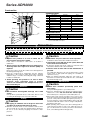
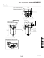
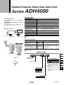
Related Products: Heavy Duty Auto Drain
Series ADH4000
Specifications
Easy maintenance
It is possible to maintain without changing
existing piping.
Auto-drain type
No need for electric power and no
waste of air.
Proof pressure
Float style drain allows automatic drain
discharge without electric power.
Aftercooler
Air tank
Air dryer
N.O. (Normally open: Open in the case of pressure loss)
Auto-drain valve type
2.5 MPa
Max. operating pressure
1.6 MPa
Operating pressure range Note)
0.05 to 1.6 MPa
Fluid
Mounting example
Float type
Note)
Compressed air
Ambient and
Fluid temperature
<Corrosive gas, flammable gas and organic solvents are not allowed.>
Max. drain discharge
400 cc/min (Pressure 0.7 MPa, in the case of water)
5 to 60°C (With no condensation)
Weight
1.2 kg (With bracket: 1.3 kg)
Paint color
Light gray
Note) Use for air compressor with flow more than 50 l /min (ANR).
Air compressor
ADH4000
ADH4000
Accessory (Option)
Description
Part no.
Bracket set
Ball valve piping set
Contents
BM58
Bracket ····································1 pc.
M6 x 10l (Hex. bolt) ················· 2 pcs.
ADH-C400
Ball valve/Rc 1/2 ··························· 1 pc.
Barrel nipple/R 1/2 ························ 2 pcs.
Elbow/Rc 1/2 ································ 1 pc.
Note) The accessories (Option) are shipped unassembled, but packed in the same
container.
How to Order
Ball valve piping set
Bracket set
JIS Symbol
ADH4000
HA
04
AT
Heavy duty
auto-drain
Accessory (Option) ∗
Nil
B
C
Basic size
Thread type
Nil
F
N
Rc
G
NPT
No option (Standard)
Bracket set
Ball valve piping set
∗ Notes
1) When more than one option is
desired, list in alphabetical order.
2) Accessories are not factory
assembled.
3) Refer to each drawing for details
of dimensions and mounting
methods.
4) Accessory “C” is available only
with Rc thread.
Port size
04 1/2 (Female thread)
14-20-51
ID
AMG
AFF
AM
Misc.
Series ADH4000
Construction
!1
q
o
i
Component Parts
u
w
y
IN
t
r
10-1
e
10-2
!0
10-3
No.
q
Description
Body
Material
Aluminum alloy
Note
Baking finish
w
Housing
Aluminum alloy
Baking finish
e
Drain guard
Aluminum alloy
Baking finish
r
Float
t
Pilot valve
y
Lever
Resin
u
Flushing button
Brass
i
Orifice
o
Diaphragm
Foam rubber
Stainless steel + Rubber
Rubber
Replacement Parts
No.
!0
Part no.
Note
Description
Repair kit for main valve ADH-D400 Kit includes parts from 10-1 to 10-5.
!1
O-ring
G85(B)
Material: NBR
Note) When changing parts, follow the instruction manual.
Do not disassemble other parts.
10-4
10-5
OUT
Precautions
Be sure to read before handling. Refer to pages 14-21-3 to 4 for Safety Instructions and Common Precautions
on the products mentioned in this catalog, and pages 14-14-6 to 8 for Precautions on every series.
Caution on Design
Mounting
Caution
Caution
1. Operate this product in an area in which the air
pressure does not exceed 1.6 MPa.
1. Install with “out port” down in a vertical position.
Inclination from the vertical line should be less than 5°.
If this value is exceeded, it could lead to an accident or
malfunction.
2. Install with at least 200 mm of free space above the
unit to allow for maintenance.
2. An air pressure of 0.05 MPa and an air compressor’s
discharge flow rates higher than 50 l/min (ANR) are
required.
3. To place this product near the air compressor, install in such a
way that the vibrations will not be transmitted.
Below these values, the air will continue to be discharged from
the drainage discharge port.
3. Keep the compressed air temperature and the ambient
temperature of the location in which this product is installed
within the range of 5 to 60°C. Exceeding this range could lead
to failure or malfunction.
4. Avoid operating this product in an area in which
corrosive gases, flammable gases or organic
solvents are contained in the compressed air or in
the surrounding air.
Selection
Caution
1. The maximum dischargeable drainage rate is 400
cc/min.
If the product is operated in excess of this value, there is a risk
of causing the drainage to flow over to the outlet side.
Piping
Caution
1. Use piping of 1/2B bore size or larger for drain inlet
and allow for unobstructed flow-in for drain.
2. Drain line should be 8 mm or more in diameter and less than
10 m in length. Do not make any upward angles in drain line.
Be sure to secure exhaust port piping since drain is under
pressure.
14-20-52
4. Install a valve to drain inlet so that maintenance is
possible.
Use a ball valve with a bore size of more than 15 mm to ensure
proper flow-in of drain. (Ball valve piping set is available as
optional accessory.)
5. When not draining sufficiently, adjust the open angle of its
bleed valve to lower the pressure inside the case, so that drainage will run through easily.
Maintenance
Caution
1. Check drain condition periodically (more than
once a day).
Then push flushing button to open exhaust valve.
2. Pilot air is exhausted from the exhaust port indicated in the
“Dimensions” section. Do not cover this exhaust port.
Clean exhaust port so that port is not blocked by dust, etc.
3. When solid foreign objects exceeding 1 mm comes in, the
main valve may become blocked. After recovering the internal
pressure of this product to 0 MPa (atmospheric pressure), remove the hexagon socket head bolt (M6) from the body part
and wash inside with water to remove foreign solid particles
blocking the main valve.
4. While operating, there may be cases where drainage will not
easily enter this product. In such a case, adjust the open angle of its bleed valve to lower the pressure a bit inside the
bowl, so that drainage will run through easily.
Heavy Duty Auto drain
Series
ADH4000
Dimensions
M6 hex. socket head bolt (including bracket set)
[Applicable hex. wrench nominal size 5]
108
100
M6 hex. socket head bolt (including bracket set)
[Applicable hex. wrench nominal size 5]
58
33
100
Pilot exhaust port
Bleed valve
Bracket mounting hole
(Both sides)
Flushing button
Drain inlet 1/2 female thread
(Refer to “How to Order” for type of thread.)
120
8
30
10
16
7
200
100
(Space for maintenance)
Bracket (Option)
Product label
155
171
189
(176)
Octagonal width across flats 30
Caution label
Hexagon width across flats 27
HA
Drain outlet 1/2 female thread
(Refer to “How to Order” for type of thread.)
AT
Option: Reference Figure of Assembly
ID
Piping example of ball valve piping set
AMG
(54)
(41)
AFF
(100)
(45)
AM
Misc.
14-20-53
Safety Instructions
These safety instructions are intended to prevent a hazardous situation and/or
equipment damage. These instructions indicate the level of potential hazard by labels of
"Caution", "Warning" or "Danger". To ensure safety, be sure to observe ISO 4414 Note 1),
JIS B 8370 Note 2) and other safety practices.
Caution : Operator error could result in injury or equipment damage.
Warning : Operator error could result in serious injury or loss of life.
Danger :
In extreme conditions, there is a possible result of serious injury or loss of life.
Note 1) ISO 4414: Pneumatic fluid power--General rules relating to systems.
Note 2) JIS B 8370: General Rules for Pneumatic Equipment
Warning
1. The compatibility of pneumatic equipment is the responsibility of the person
who designs the pneumatic system or decides its specifications.
Since the products specified here are used in various operating conditions, their compatibility for the
specific pneumatic system must be based on specifications or after analysis and/or tests to meet your
specific requirements. The expected performance and safety assurance will be the responsibility of the
person who has determined the compatibility of the system. This person should continuously review
the suitability of all items specified, referring to the latest catalog information with a view to giving due
consideration to any possibility of equipment failure when configuring a system.
2. Only trained personnel should operate pneumatically operated machinery
and equipment.
Compressed air can be dangerous if an operator is unfamiliar with it. Assembly, handling or repair of
pneumatic systems should be performed by trained and experienced operators.
3. Do not service machinery/equipment or attempt to remove components until
safety is confirmed.
1. Inspection and maintenance of machinery/equipment should only be performed once measures to
prevent falling or runaway of the driver objects have been confirmed.
2. When equipment is to be removed, confirm the safety process as mentioned above. Cut the supply
pressure for this equipment and exhaust all residual compressed air in the system.
3. Before machinery/equipment is restarted, take measures to prevent shooting-out of cylinder piston
rod, etc.
4. Contact SMC if the product is to be used in any of the following conditions:
1. Conditions and environments beyond the given specifications, or if product is used outdoors.
2. Installation on equipment in conjunction with atomic energy, railway, air navigation, vehicles,
medical equipment, food and beverages, recreation equipment, emergency stop circuits, clutch and
brake circuits in press applications, or safety equipment.
3. An application which has the possibility of having negative effects on people, property, or animals,
requiring special safety analysis.
14-21-3
Common Precautions
Be sure to read before handling.
For detailed precautions on every series, refer to main text.
Selection
Warning
1. Confirm the specifications.
Products represented in this catalog are designed for use in
compressed air appllications only (including vacuum), unless
otherwise indicated.
Do not use the product outside their design parameters.
Please contact SMC when using the products in applications
other than compressed air (including vacuum).
Mounting
Warning
1. Instruction manual
Install the products and operate them only after reading the
instruction manual carefully and understanding its contents.
Also keep the manual where it can be referred to as
necessary.
4. Use clean air
If the compressed air supply is contaminated with chemicals,
cynthetic materials, corrosive gas, etc., it may lead to break
down or malfunction.
Operating Environment
Warning
1. Do not use in environments where the product
is directly exposed to corrosive gases,
chemicals, salt water, water or steam.
2. Do not expose the product to direct sunlight
for an extended period of time.
3. Do not use in a place subject to heavy
vibrations and/or shocks.
4. Do not mount the product in locations where it
is exposed to radiant heat.
Maintenance
2. Securing the space for maintenance
When installing the products, please allow access for
maintenance.
3. Tightening torque
When installing the products, please follow the listed torque
specifications.
Piping
Caution
1. Before piping
Make sure that all debris, cutting oil, dust, etc, are removed
from the piping.
2. Wrapping of pipe tape
When screwing piping or fittings into ports, ensure that chips
from the pipe threads or sealing material do not get inside the
piping. Also, when the pipe tape is used, leave 1.5 to 2 thread
ridges exposed at the end of the threads.
Air Supply
Warning
1. Operating fluid
Please consult with SMC when using the product in
applications other than compressed air (including vacuum).
Regarding products for general fluid, please ask SMC about
applicable fluids.
2. Install an air dryer, aftercooler, etc.
Excessive condensate in a compressed air system may cause
valves and other pneumatic equipment to malfunction.
Installation of an air dryer, after cooler etc. is recommended.
3. Drain flushing
If condensate in the drain bowl is not emptied on a regular
basis, the bowl will over flow and allow the condensate to
enter the compressed air lines.
If the drain bowl is difficult to check and remove, it is
recommended that a drain bowl with the auto-drain option be
installed.
For compressed air quality, refer to “Air Preparation
Equipment” catalog.
14-21-4
Warning
1. Maintenance procedures are outlined in the
operation manual.
Not following proper procedures could cause the product to
malfunction and could lead to damage to the equipment or
machine.
2. Maintenance work
If handled improperly, compressed air can be dangerous.
Assembly, handling and repair of pneumatic systems should
be performed by qualified personnel only.
3. Drain flushing
Remove drainage from air filters regularly. (Refer to the
specifications.)
4. Shut-down before maintenance
Before attempting any kind of maintenance make sure the
supply pressure is shut of and all residual air pressure is
released from the system to be worked on.
5. Start-up after maintenance and inspection
Apply operating pressure and power to the equipment and
check for proper operation and possible air leaks. If operation
is abnormal, please verify product set-up parameters.
6. Do not make any modifications to be product.
Do not take the product apart.
Quality Assurance Information
(ISO 9001, ISO 14001)
Reliable quality of products in the global market
To enable our customers throughout
the world to use our products with
even greater confidence, SMC has
obtained certification for international
standards “ISO 9001” and “ISO
14001”, and created a complete
structure for quality assurance and
environmental
controls.
SMC
products pursue to meet its
customers’ expectations while also
considering company’s contribution in
society.
SMC’s quality control system
Make customers our
first priority, offering
them reliable and
friendly service.
Produce the highest
quality with the
participation of all
employees.
Create new
products using the
latest technology,
and offer the finest
products in a
timely manner.
Quality policies
Market research
Product planning
After service
Sales coordination
Quality management system
ISO 9001
This is an international standard for quality control
and quality assurance. SMC has obtained a large
number of certifications in Japan and overseas,
providing assurance to our customers throughout
the world.
Quality system
education
Training of
suppliers
Research
Education
Design
Training
Development
Production
New product evaluation
Reliability design
Reliability testing
New technical
development
Process control
Inspection, testing, etc.
Initial production control
Quality control activities
Environmental management system
ISO 14001
This is an international standard related to
environmental management systems and
environmental inspections. While promoting
environmentally friendly automation technology,
SMC is also making diligent efforts to preserve
the environment.
14-21-5
SMC Product Conforming to Inter
SMC products complying with EN/ISO, CSA/UL standards are supporting
CE Mark
The CE mark indicates that machines and components meet essential requirements of all the EC Directives
applied.
It has been obligatory to apply CE marks indicating conformity with EC Directives when machines and
components are exported to the member Nations of the EU.
Once “A manufacturer himself” declares a product to be safe by means of CE marking (declaration of
conformity by manufacturer), free distribution inside the member Nations of the EU is permissible.
CE Mark
SMC provides CE marking to products to which EMC and Low Voltage Directives have been applied, in
accordance with CETOP (European hydraulics and pneumatics committee) guide lines.
As of February 1998, the following 18 countries will be obliged to conform to CE mark legislation
Iceland, Ireland, United Kingdom, Italy, Austria, Netherlands, Greece, Liechtenstein, Sweden, Spain, Denmark,
Germany, Norway, Finland, France, Belgium, Portugal, Luxembourg
EC Directives and Pneumatic Components
• Machinery Directive
The Machinery Directive contains essential health and safety requirements for machinery, as applied to
industrial machines e.g. machine tools, injection molding machines and automatic machines. Pneumatic
equipment is not specified in Machinery Directive. However, the use of SMC products that are certified as
conforming to EN Standards, allows customers to simplify preparation work of the Technical Construction File
required for a Declaration of Conformity.
• Electromagnetic Compatibility (EMC) Directive
The EMC Directive specifies electromagnetic compatibility. Equipment which may generate electromagnetic
interference or whose function may be compromised by electromagnetic interference is required to be immune
to electromagnetic affects (EMS/immunity) without emitting excessive electromagnetic affects (EMI/emission).
• Low Voltage Directive
This directive is applied to products, which operate above 50 VAC to 1000 VAC and 75 VDC to 1500 VDC
operating voltage, and require electrical safety measures to be introduced.
• Simple Pressure Vessels Directive
This directive is applied to welded vessels whose maximum operating pressure (PS) and volume of vessel (V)
exceed 50 bar/L. Such vessels require EC type examination and then CE marking.
14-21-6
SMC Product Conforming to International Standards
national Standards
you to comply with EC directives and CSA/UL standards.
Mark of compliance
for CSA/UL
Mark of compliance
for CSA
CSA Standards & UL Standards
UL and CSA standards have been applied in North America (U.S.A. and Canada) symbolizing safety of electric
products, and are defined to mainly prevent danger from electric shock or fire, resulting from trouble with
electric products. Both UL and CSA standards are acknowledged in North America as the first class certifying
body. They have a long experience and ability for issuing product safety certificate. Products approved by CSA
or UL standards are accepted in most states and governments beyond question.
Since CSA is a test certifying body as the National Recognized Testing Laboratory (NRTL) within the
jurisdiction of Occupational Safety and Health Administration (OSHA), SMC was tested for compliance with
CSA Standards and UL Standards at the same time and was approved for compliance with the two Standards.
The above CSA NRTL/C logo is described on a product label in order to indicate that the product is approved
by CSA and UL Standards.
TSSA (MCCR) Registration Products
TSSA is the regulation in Ontario State, Canada. The products that the operating pressure is more than 5 psi
(0.03 MPa) and the piping size is bigger than 1 inch. fall into the scope of TSSA regulation.
Products conforming to CE Standard
With CE symbol for simple visual recognition
In this catalog each accredited product series is indicated with a
CE mark symbol. However, in some cases, every available
models may not meet CE compliance. Please visit our web site
for the latest selection of available models with CE mark.
http://www.smcworld.com
14-21-7
SMC’s Global Service Network
America
Europe
U.S.A. SMC Corporation of America
3011 North Franklin Road Indianapolis, IN 46226, U.S.A.
TEL: 317-899-4440 FAX: 317-899-3102
U.K. SMC Pneumatics (U.K.) Ltd.
Vincent Avenue, Crownhill, Milton Keynes, MK8 0AN, Backinghamshire, U.K.
TEL: 01908-563888 FAX: 01908-561185
CANADA SMC Pneumatics (Canada) Ltd.
6768 Financial Drive Mississauga, Ontario, L5N 7J6 Canada
TEL: 905-812-0400 FAX: 905-812-8686
GERMANY SMC Pneumatik GmbH
Boschring 13-15 D-63329 Egelsbach, Germany
TEL: 06103-4020 FAX: 06103-402139
MEXICO SMC Corporation (Mexico), S.A. DE C.V.
Carr. Silao-Trejo K.M. 2.5 S/N, Predio San Jose del Duranzo
C.P. 36100, Silao, Gto., Mexico
TEL: 472-72-2-55-00 FAX: 472-72-2-59-44/2-59-46
ITALY SMC Italia S.p.A.
Via Garibaldi 62 I-20061 Carugate Milano, Italy
TEL: 02-9271365 FAX: 02-9271365
CHILE SMC Pneumatics (Chile) S.A.
Av. La Montaña 1,115 km. 16,5 P. Norte Parque
Industrial Valle Grande, Lampa Santiago, Chile
TEL: 02-270-8600 FAX: 02-270-8601
ARGENTINA SMC Argentina S.A.
Teodoro Garcia 3860 (1427) Buenos Aires, Argentina
TEL: 011-4555-5762 FAX: 011-4555-5762
BOLIVIA SMC Pneumatics Bolivia S.R.L.
Avenida Beni Numero 4665
Santa Cruz de la Sierra-Casilla de Correo 2281, Bolivia
TEL: 591-3-3428383 FAX: 591-3-3449900
VENEZUELA SMC Neumatica Venezuela S.A.
Apartado 40152, Avenida Nueva Granada, Edificio Wanlac,
Local 5, Caracas 1040-A, Venezuela
TEL: 2-632-1310 FAX: 2-632-3871
FRANCE SMC Pneumatique S.A.
1 Boulevard de Strasbourg, Parc Gustave Eiffel, Bussy Saint Georges, F-77600
Marne La Vallee Cedex 3 France
TEL: 01-64-76-10-00 FAX: 01-64-76-10-10
SWEDEN SMC Pneumatics Sweden AB
Ekhagsvägen 29-31, S-141 05 Huddinge, Sweden
TEL: 08-603-07-00 FAX: 08-603-07-10
SWITZERLAND SMC Pneumatik AG
Dorfstrasse 7, Postfach 117, CH-8484 Weisslingen, Switzerland
TEL: 052-396-3131 FAX: 052-396-3191
AUSTRIA SMC Pneumatik GmbH (Austria)
Girakstrasse 8, A-2100 Korneuburg, Austria
TEL: 0-2262-6228-0 FAX: 0-2262-62285
SPAIN SMC España, S.A.
Zuazobidea 14 Pol. Ind. Júndiz 01015 Vitoria, Spain
TEL: 945-184-100 FAX: 945-184-510
PERU (Distributor) IMPECO Automatizacion Industrial S.A.
AV. Canevaro 752, Lince, Lima, Peru
TEL: 1-471-6002 FAX: 1-471-0935
IRELAND SMC Pneumatics (Ireland) Ltd.
2002 Citywest Business Campus, Naas Road, Saggart, Co. Dublin, Ireland
TEL: 01-403-9000 FAX: 01-466-0385
URUGUAY (Distributor) BAKO S.A.
Galicia 1650 esq. Gaboto C.P. 11200, Montevideo, Uruguay
TEL: 2-401-6603 FAX: 2-409-4306
NETHERLANDS (Associated company) SMC Pneumatics BV
De Ruyterkade 120, NL-1011 AB Amsterdam, Netherlands
TEL: 020-5318888 FAX: 020-5318880
BRAZIL SMC Pneumaticos Do Brasil Ltda.
Rua. Dra. Maria Fidelis, nr. 130, Jardim Piraporinha-Diadema-S.P.
CEP: 09950-350, Brasil
TEL: 11-4051-1177 FAX: 11-4071-6636
GREECE (Distributor) S.Parianopoulos S.A.
7, Konstantinoupoleos Street 11855 Athens, Greece
TEL: 01-3426076 FAX: 01-3455578
COLOMBIA (Distributor) Airmatic Ltda.
Calle 18 69-05 Apart. Aereo 081045 Santa Fe de Bogotá, Colombia
TEL: 1-424-9240 FAX: 1-424-9260
DENMARK SMC Pneumatik A/S
Knudsminde 4 B DK-8300
Odder, Denmark
TEL: 70252900 FAX: 70252901
14-21-20
SMC’s Global Service Network
Europe
Oceania/Asia
FINLAND SMC Pneumatics Finland OY
PL72, Tiistinniityntie 4, SF-02231 ESP00, Finland
TEL: 09-8595-80 FAX: 09-8595-8595
AUSTRALIA SMC Pneumatics (Australia) Pty.Ltd.
14-18 Hudson Avenue Castle Hill NSW 2154, Australia
TEL: 02-9354-8222 FAX: 02-9894-5719
NORWAY SMC Pneumatics Norway A/S
Vollsveien 13C, Granfoss Næringspark N-1366 LYSAKER, Norway
TEL: 67-12-90-20 FAX: 67-12-90-21
NEW ZEALAND SMC Pneumatics (New Zealand) Ltd.
8C Sylvia Park Road Mt.Wellington Auckland, New Zealand
TEL: 09-573-7007 FAX: 09-573-7002
BELGIUM (Distributor) SMC Pneumatics N.V./S.A.
Nijverheidsstraat 20 B-2160 Wommelgem Belguim
TEL: 03-355-1464 FAX: 03-355-1466
TAIWAN SMC Pneumatics (Taiwan) Co.,Ltd.
17, Lane 205, Nansan Rd., Sec.2, Luzhu-Hsiang, Taoyuan-Hsien, TAIWAN
TEL: 03-322-3443 FAX: 03-322-3387
POLAND SMC Industrial Automation Polska Sp.z.o.o.
ul. Konstruktorska 11A, PL-02-673 Warszawa, Poland
TEL: 022-548-5085 FAX: 022-548-5087
HONG KONG SMC Pneumatics (Hong Kong) Ltd.
29/F, Clifford Centre, 778-784 Cheung, Sha Wan Road, Lai Chi Kok, Kowloon,
Hong Kong
TEL: 2744-0121 FAX: 2785-1314
TURKEY (Distributor) Entek Pnömatik San.ve Tic. Ltd. Sti
Perpa Tic. Merkezi Kat:11 No.1625 80270 Okmeydani Istanbul, Türkiye
TEL: 0212-221-1512 FAX: 0212-221-1519
RUSSIA SMC Pneumatik LLC.
36/40 Sredny prospect V.O. St. Petersburg 199004, Russia
TEL: 812-118-5445 FAX: 812-118-5449
CZECH SMC Industrial Automation CZ s.r.o.
Hudcova 78a, CZ-61200 Brno, Czech Republic
TEL: 05-4121-8034 FAX: 05-4121-8034
HUNGARY SMC Hungary Ipari Automatizálási kft.
Budafoki ut 107-113 1117 Budapest
TEL: 01-371-1343 FAX: 01-371-1344
ROMANIA SMC Romania S.r.l.
Str. Frunzei, Nr. 29, Sector 2, Bucharest, Romania
TEL: 01-3205111 FAX: 01-3261489
SLOVAKIA SMC Priemyselná automatizáciá, s.r.o
Nova 3, SK-83103 Bratislava
TEL: 02-4445-6725 FAX: 02-4445-6028
SLOVENIA SMC Industrijska Avtomatilca d.o.o.
Grajski trg 15, SLO- 8360 Zuzemberk, Slovenia
TEL: 07388-5240 FAX: 07388-5249
SOUTH AFRICA (Distributor) Hyflo Southern Africa (Pty.) Ltd.
P.O.Box 240 Paardeneiland 7420 South Africa
TEL: 021-511-7021 FAX: 021-511-4456
EGYPT (Distributor) Saadani Trading & Ind. Services
15 Sebaai Street, Miami 21411 Alexandria, Egypt
TEL: 3-548-50-34 FAX: 3-548-50-34
SINGAPORE SMC Pneumatics (S.E.A.) Pte. Ltd.
89 Tuas Avenue 1, Jurong Singapore 639520
TEL: 6861-0888 FAX: 6861-1889
PHILIPPINES SHOKETSU SMC Corporation
Unit 201 Common Goal Tower, Madrigal Business Park,
Ayala Alabang Muntinlupa, Philippines
TEL: 02-8090565 FAX: 02-8090586
MALAYSIA SMC Pneumatics (S.E.A.) Sdn. Bhd.
Lot 36 Jalan Delima1/1, Subang Hi-Tech Industrial Park, Batu 3 40000 Shah Alam
Selangor, Malaysia
TEL: 03-56350590 FAX: 03-56350602
SOUTH KOREA SMC Pneumatics Korea Co., Ltd.
Woolim e-BIZ Center (Room 1008), 170-5, Guro-Dong, Guro-Gu,
Seoul, 152-050, South Korea
TEL: 02-3219-0700 FAX: 02-3219-0702
CHINA SMC (China) Co., Ltd.
7 Wan Yuan St. Beijing Economic & Technological Development Zone 100176, China
TEL: 010-67882111 FAX: 010-67881837
THAILAND SMC Thailand Ltd.
134/6 Moo 5, Tiwanon Road, Bangkadi, Amphur Muang, Patumthani 12000, Thailand
TEL: 02-963-7099 FAX: 02-501-2937
INDIA SMC Pneumatics (India) Pvt. Ltd.
D-107 to 112, Phase-2, Extension, Noida, Dist. Gautaim Budh Nagar,
U.P. 201 305, India
TEL: (0120)-4568730 FAX: 0120-4568933
INDONESIA (Distributor) P.T. Riyadi Putera Makmur
Jalan Hayam Wuruk Komplek Glodok Jaya No. 27-28 Jakarta 11180 Indonesia
TEL: 021-625 5548 FAX: 021-625 5888
PAKISTAN (Distributor) Jubilee Corporation
First Floor Mercantile Centre, Newton Road Near Boulton Market P.O. Box 6165
Karachi 74000 Pakistan
TEL: 021-243-9070/8449 FAX: 021-241-4589
ISRAEL (Distributor) Baccara Automation Control
Kvutzat Geva 18915 Israel
TEL: 04-653-5960 FAX: 04-653-1445
SAUDI ARABIA (Distributor) Assaggaff Trading Est.
P.O. Box 3385 Al-Amir Majed Street, Jeddah-21471, Saudi Arabia
TEL: 02-6761574 FAX: 02-6708173
14-21-21