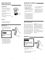
1
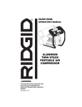
OF45150
OPERATOR’S MANUAL
TWIN STACK
PORTABLE AIR
COMPRESSOR
! WARNING
Read and follow all Safety Rules
before first use of this product.
IN610300AV
Printed in U.S.A.
Table of Contents
Section
Safety Instructions
Page
Section
Table of Contents . . . . . . . . . . . . . . . .2
Page
Getting to Know Your Air
Compressor . . . . . . . . . . . . . . . . . . .11
Regulated Outlet Gauge . . . . . . . . .11
Tank Pressure Gauge . . . . . . . . . . .11
Regulator Knob . . . . . . . . . . . . . . . .12
Air Filter . . . . . . . . . . . . . . . . . . . . . .12
ASME Safety Valve . . . . . . . . . . . . .12
Safety Instructions . . . . . . . . . . . . . . .3
Safety Signal Words . . . . . . . . . . . . .3
Before Using the Air
Compressor . . . . . . . . . . . . . . . . . . . .3
Spraying Precautions . . . . . . . . . . . .5
Breathable Air Warning . . . . . . . . . . .5
Warning Labels . . . . . . . . . . . . . . . . .6
Operating Your Air Compressor . . .13
For Trouble-Free Operation . . . . . .13
Moisture in Compressed Air . . . . . .13
Motor Specifications and
Electrical Requirements . . . . . . . . . .7
Power Supply and Motor
Specifications . . . . . . . . . . . . . . . . . .7
General Electrical Connections . . . . .7
110-120 Volt, 60 Hz Tool
Information . . . . . . . . . . . . . . . . . . . .8
Extension Cords . . . . . . . . . . . . . . . .9
Thermal Overload Protector . . . . . . .9
Maintenance . . . . . . . . . . . . . . . . . . .13
Tank . . . . . . . . . . . . . . . . . . . . . . . . .14
Filter Removal, Inspection, and
Replacement . . . . . . . . . . . . . . . . . .15
Lubrication . . . . . . . . . . . . . . . . . . . .15
Storage . . . . . . . . . . . . . . . . . . . . . .15
Maintenance Schedule . . . . . . . . . .15
Glossary of Terms . . . . . . . . . . . . . . .9
Troubleshooting . . . . . . . . . . . . . . . .16
Unpacking and Checking
Content . . . . . . . . . . . . . . . . . . . . . . .10
Repair Parts . . . . . . . . . . . . . . . . . . .18
Notes . . . . . . . . . . . . . . . . . . . . . . . . .22
Installation . . . . . . . . . . . . . . . . . . . .10
Warranty . . . . . . . . . . . . . . . . . . . . . .24
Warning indicates
! WARNING a potentially hazardous situation which, if not avoided,
COULD result in death or serious injury.
This manual contains information that is
very important to know and understand.
This information is provided for SAFETY
and to PREVENT EQUIPMENT PROBLEMS. To help recognize this information, observe the following symbols.
Caution indicates a
potentially hazardous situation which, if not avoided,
MAY result in minor or moderate injury.
!
Safety Signal Words
Danger indicates
an imminently hazardous situation which, if not avoided,
WILL result in death or serious injury.
!
DANGER
Notice indicates
important information, that if not followed, may cause damage to equipment.
!NOTICE
Before Using the Air Compressor
objects, chemical spills, oil, solvents,
and wet floors.
Air compressors are utilized in a variety
of air system applications. Because air
compressors and other components
(material pump, spray gun, filters, lubrications, hoses, etc.) used make up a
high pressure pumping system, the following safety precautions should be
observed at all times. Only persons well
acquainted with these rules of safe operation should be allowed to use the air
compressor.
4. Never point a spray gun at oneself or
any other person. Accidental discharge may result in serious injury.
5. Check hoses for weak or worn condition, before each use, making certain
all connections are secure; do not
use if deficiency is found. Notify an
authorized service facility for examination or repair.
6. Release all pressures within system
slowly; dust and debris may be harmful.
All electrical
! WARNING work should be
done by a qualified (licensed or
certified) electrician. On a properly wired circuit, the black
wires supply a voltage potential
even when the unit is off.
Disconnect
! WARNING power and
depressurize system before
servicing air compressor! (Turn
pressure regulator knob fully
clockwise after shutting off
compressor.)
1. Read instruction manuals for each
component carefully, before attempting to assemble, disassemble or
operate your particular system.
7. Follow all local electrical and safety
codes, as well as the National
Electrical Code (NEC) and the
Occupational Safety and Health Act
(OSHA).
2. Do not exceed pressure rating of any
component in system.
3. Protect material lines and air lines
from damage or puncture. Keep hose
and power cable away from sharp
2
CAUTION
3
Safety Instructions (continued)
8. Wiring and fuses should follow electrical codes, current capacity, and be
properly grounded.
19. Spray in a well ventilated area, to
keep fumes from collecting and causing health and fire hazards.
9. Electric motors must be securely and
adequately grounded. See grounding
instructions and extension cord information, in this manual.
20. Do not spray in vicinity of open
flames or other places where a spark
can cause ignition. Do not smoke
when spraying paint, insecticides, or
other flammable substances.
10. Always disconnect power source
before working on or near a motor, or
its connected load. If power disconnect point is out-of-sight, lock it in the
open position and tag to prevent
unexpected application of power.
21. Use a respirator when spraying.
22. NEVER reset safety valve or pressure switch. Keep safety valve free
from paint and other accumulations.
This provides safety against over
pressure.
11. Guard all moving parts; keep visitors
away. Never allow children in work
area.
23. Do regular maintenance; keep all
nuts, bolts, and screws tight, to be
sure equipment is in safe working
condition .
12. Use only a properly grounded outlet
that will accept a three pronged plug,
and wear shoes to prevent shock
hazards.
24. Keep cleaning rags and other flammable waste materials in a tightly
closed metal container and dispose of
later in the proper fashion.
13. Be careful when touching exterior of
operating motor; it may be hot
enough to cause injury.
25. Drain tanks of moisture after each
day’s use. If unit will not be used for a
while, it is best to leave drain cock
open until such time as it is to be
used. This will allow moisture to completely drain out and help prevent
corrosion of inside of tank.
14. Protect power cable from coming in
contact with sharp objects.
15. Clean electrical or electronic equipment with an approved cleaning
agent, such as dry, nonflammable
cleaning solvent.
26. Inspect tank yearly for rust, pin holes
or any other imperfections that could
cause it to become unsafe. NEVER
weld or drill holes in air tank.
16. To avoid spontaneous combustion,
discard waste rags into approved
metal waste cans.
17. Never store flammable liquids or
gases in vicinity of compressor.
18. When spraying with solvent of toxic
chemicals, follow instructions provided by the chemical manufacturer.
4
Spraying Precautions
3. Do not direct paint or other sprayed
material at the compressor. Locate
compressor as far away from the
spraying area as possible to minimize
overspray accumulation on the compressor.
! WARNING
Do not spray flammable materials in vicinity of open flame or
near ignition sources including
the compressor unit.
4. When spraying or cleaning with solvents or toxic chemicals, follow the
instructions provided by the chemical
manufacturer.
1. Do not smoke when spraying paint,
insecticides, or other flammable substances.
2. Use a face mask/respirator when spraying and
spray in a well ventilated
area to prevent health and
fire hazards.
!
DANGER
Breathable Air Warning
This compressor/pump is not equipped and should not be used “as
is” to supply breathing quality air. For any application of air for
human consumption, the air compressor/pump will need to be fitted
with suitable in-line safety and alarm equipment. This additional
equipment is necessary to properly filter and purify the air to meet
minimal specifications for Grade D breathing as described in
Compressed Gas Association Commodity Specification G 7.1 - 1966,
OSHA 29 CFR 1910. 134, and/or Canadian Standards Associations
(CSA).
DISCLAIMER OF WARRANTIES
In the event the compressor is used for the purpose of breathing air
application and proper in-line safety and alarm equipment is not
simultaneously used, existing warranties shall be voided, and
Campbell Hausfeld disclaims any liability whatsoever for any loss,
personal injury or damage.
5
Safety Instructions (continued)
Motor Specifications and
Electrical Requirements
Warning Labels
Power Supply and Motor Specifications
Find and read all warning labels found on
the air compressor shown below
The A-C motor used on this tool has the
following specifications. It is wired at the
factory for operation on 110V-120V AC,
60 Hz service.
! WARNING
To reduce the risk of electrical
hazards, fire hazards or damage
to the tool, use proper circuit
protection. Your tool is wired at
the factory for operation using
the voltage shown. Connect
tool to a power line with the
appropriate voltage and a 15amp branch circuit. Use a 15amp time delay type fuse or circuit breaker. To reduce the risk
of shock or fire, if power cord is
worn or cut, or damaged in any
way, have it replaced immediately.
Rated HP
Voltage
Amperes
Hertz (Cycles)
Phase
RPM
Rotation of Shaft
Wired for 120V
1 1/2
110-120
13
60
Single
3450
Clockwise
General Electrical Connections
!
! WARNING
DANGER
Do not permit fingers to touch
the terminals of plug when
installing or removing the plug
to or from the outlet.
To reduce the risk of electrocution:
1. Use only identical replacement parts when servicing.
Servicing should be performed by a qualified technician.
DK724100AV 10003
Figure 1
6
2. Do not use in rain or where
floor is wet. This too is
intended for indoor residential use only.
7
Motor Specifications and
Electrical Requirements (continued)
Thermal Overload Protector
4. Lack of proper ventilation.
!
110-120 volt, 60Hz Tool Information
If the grounding instructions are not completely understood, or if you are in doubt
as to whether the tool is properly grounded check with a qualified electrician or
service personnel.
The plug supplied on your tool may not
fit into the outlet you are planning to use.
Your local electrical code may require
slightly different power cord plug connections. If these differences exist refer to
and make the proper adjustments per
you local code before your tool is
plugged in and turned on.
! WARNING
In the event of a malfunction or breakdown, grounding provides a path of least
resistance for electrical current to reduce
the risk of electric shock. This tool is
equipped with an electric cord having an
equipment-grounding conductor and a
grounding plug, as shown. The plug must
be plugged into a matching outlet that is
properly installed and grounded in accordance with all local codes and ordinances.
If not properly grounded, this
tool can cause an electrical
shock, particularly when used
in damp locations, in proximity
of plumbing, or out of doors.
5. Unit is being used with an extension
cord.
CAUTION
This compressor is equipped
with an automatic reset thermal
overload protector which will
shut off motor if it becomes
overheated.
See Troubleshooting Chart for corrective
action.
!
CAUTION
The motor must be allowed to
cool down before start-up is
possible. The motor will automatically restart without warning if left plugged into electrical
outlet, if the motor is turned on.
If thermal overload protector shuts motor
OFF frequently look for the following
causes.
1. Low voltage.
2. Wrong gauge wire.
3. Clogged air filter.
Glossary of Terms
ASME Safety Valve
A safety valve that automatically releases
the air if the air receiver (tank) pressure
exceeds the preset maximum.
3-Prong Plug
Do not modify the plug provided. If it will
not fit the outlet, have the proper outlet
installed by a qualified electrician.
Properly
Grounded
3-Prong
Outlet
Improper connection of the equipmentgrounding conductor can result in a risk
of electric shock. The conductor with
insulation having an outer surface that is
green with or without yellow stripes is the
equipment-grounding conductor. If repair
or replacement of the electric cord or
plug is necessary, do not connect the
equipment-grounding conductor to a live
terminal.
TEST
RESET
Grounding Prong
Figure 2
Extension Cords
2. To avoid loss of power and overheating, additional air hose must be used
to reach work area instead of extension cords.
1. The air compressor should be located
where it can be directly plugged into
an outlet. An extension cord should
not be used with this unit.
8
allows the intermittent use of an air tool
with an air requirement higher than the
compressor’s rated delivery.
Volts or Voltage
A measurement of the force of an electrical current.
PSI (Pounds per Square Inch)
Measurement of the pressure exerted by
the force of the air. The actual psi output
is measured by a pressure gauge on the
compressor
Amps or Amperage
A measure of the electrical force minus
the resistance on an electrical line.
Ridgid air compressors require 15 amps
for operation. Be sure the compressor
will operate on an electrical line with the
proper amps. If other appliances operate
on the same line, the will reduce the
available amps. If the amperage is not
adequate, the result will be blown fuses
or tripped circuits.
SCFM (Standard Cubic Feet per
Minute)
Sometimes called CFM (Cubic Feet per
Minute). Measurement of air volume
delivered by the compressor.
Air Delivery
A combination of psi and SCFM. The air
delivery required by a tool is stated as
(number) SCFM at (number) psi. The
combination of these figures determines
what size unit is needed.
Regulator
A control that adjusts the line pressure to
the proper amount needed to operate
spray guns and air tools.
Air Tank Capacity
The volume of air stored in the tank and
available for immediate use. A large tank
Tanks Pressure Gauge
Indicates tank pressure in psi.
9
Glossary of Terms (Continued)
Getting to Know Your Air Compressor
Line Pressure Gauge
Displays the current line pressures. It is
regulated by the regulator knob.
2
1
Cut-in/Cut-off Pressure
Specific psi at which a compressor starts
and stops while refilling the air tank.
Pressure Tank
Gauge
Regulated
Outlet Gauge
Unpacking and Checking Contents
1. Remove the air compressor from the
carton.
! WARNING
2. Place the compressor on a secure,
stationary work surface and look it
over carefully.
For your own safety, never
operate unit until all assembly
steps are complete and until
you have read and understood
the entire operator’s manual.
! WARNING
Do not operate unit if damaged
during shipping, handling or
use. Damage may result in
bursting and cause injury or
property damage.
2. Operate compressor in a ventilated
area so that compressor may be
properly cooled.
Regulator
Knob
! WARNING
To reduce the risk of injury, if
any parts are missing, do not
attempt to operate the air compressor until the missing parts
are obtained and installed correctly.
Installation
1. Check and tighten all bolts, fittings,
etc., before operating compressor.
3
4. To avoid loss of power and overheating, additional air hose must be used
to reach work area instead of extension cords.
4
Figure 3
1. Regulated Outlet Gauge
2. Tank Pressure Gauge
1. This gauge shows at-a-glance, air
pressure at outlet. Air pressure is
measured in pounds per square inch
(PSI). Most tools have maximum pressure ratings. Never exceed the maximum pressure rating of the tool you
are using.
Gauge shows pressure in air receiver
indicating compressor is building pressure properly.
2. Be sure this gauge reads ZERO
before changing air tools or disconnecting hose from outlet.
3. Compressor should be located where
it can be directly plugged into an outlet. An extension cord should not be
used with this unit.
10
Air Filter
11
Getting to Know Your Air
Compressor (Continued)
Operating Your Air Compressor
3. Regulator Knob
1. Read instructions: Carefully read
through this owner’s manual
BEFORE OPERATING the new air
compressor. It contains information
about operation and maintenance of
unit.
For Trouble-Free Operation
1. This knob controls air pressure to an
air operated tool or paint spray gun.
Close
2. Turning knob clockwise increases air
pressure at outlet.
3. Turning counterclockwise will lower air
pressure at outlet.
Attach
Hose
4. Fully counterclockwise will shut off flow
of air completely.
Figure 4
4. Air Filter
The air filter keeps dirt and debris from
entering the compressor pump.
3. Change air filter: Never run compressor without an air filter nor with a
clogged air filter. Replace with a new
filter when the element is dirty.
2. Drain tank daily: Depressurize system
prior to draining tank. Open tank
drain valve and drain moisture from
tank. This helps prevent tank corrosion and keeps oil and moisture out
of the compressed air system. Be
Moisture in Compressed Air
Moisture in compressed air will form into
droplets as it comes from an air compressor pump. When humidity is high or
when a compressor is in continuous use
for an extended period of time, this moisture will collect in the tank. When using a
paint spray or sandblast gun, this water
will be carried from the tank through the
hose, and out of the gun as droplets
mixed with the spray material.
ASME Safety Valve
1. This valve automatically releases air if
air receiver pressure exceeds preset
maximum.
!
Open
sure to close tank drain valve tightly
before operating compressor.
DANGER
Do not attempt to tamper with
this valve!
Figure 5
2. This valve should be checked occasionally by pulling the ring by hand. If
air leaks after ring has been released,
or valve is stuck and cannot be actuated by ring, it MUST be replaced.
IMPORTANT: This condensation will
cause water spots in a paint job, especially when spraying other than water
based paints. If sandblasting, it will
cause the sand to cake and clog the gun,
rendering it ineffective.
A filter in the air line, located as near to
the gun as possible, will help eliminate
this moisture.
Maintenance
! WARNING
Release all pressure and disconnect power before making
any repair.
1. Check compressor for any visible
problems, especially check air filter to
be sure it is clean.
2. Pull ring on safety valve and allow it to
snap back to normal position.
12
Figure 6
13
Maintenance (Continued)
Filter Removal, Inspection and Replacement
To change a filter, pull off the filter housing
cover. If filter element is dirty, replace element or entire filter.
! WARNING
Safety valve must be replaced if
it cannot be actuated or it leaks
air after ring is released.
3. Daily with compressor shut off:
Depressurize system prior to draining
tank. Drain moisture from tank by
opening the tank drain valve underneath the tank.
4. Turn power OFF and clean dust and
dirt from motor, tank, air lines and
pump cooling fins.
Lubrication
Tank
Drain
Valve
Figure 7
IMPORTANT: Unit should be located as
far from spraying area as hose will allow
to prevent over-spray from clogging filter.
NOTE: The air filter in the filter housing
on the side of the head must be checked
and cleaned periodically, more often if
used under very dusty conditions or
when a great deal of fog from spraying is
allowed to circulate near unit.
This is an oilless type compressor requiring no lubrication.
Storage
1. When not in use, compressor should be 3. Hose should be disconnected and hung
stored in a cool dry place.
open ends down to allow any moisture
to drain.
2. Tank should be drained of moisture.
Maintenance Schedule
Operation
Daily
l
Drain Tank
Tank
!
Check Air Filter
DANGER
Never attempt to repair or modify a tank! Welding, drilling or
any other modification will
weaken the tank resulting in
damage from rupture or explosion. Always replace worn,
cracked or damaged tanks.
The tank should be carefully inspected at
a minimum of once a year. Look for
cracks forming near the welds. If a crack
is detected, remove pressure from tank
immediately and replace.
l
l
Check Safety Valve
l
Blow Dirt From Inside Motor
NOTICE
Drain liquid from tank daily.
14
Weekly
15
Troubleshooting
TROUBLE
Thermal overload
protector cuts out
repeatedly
! WARNING
For your own safety do not try
and run the air compressor
while troubleshooting.
TROUBLE
Compressor will not
run
PROBABLE CAUSE
1. Unit is plugged into
extension cord
2. No electrical power
5. Thermal overload open
6. Pressure switch bad
Fuses blow/circuit
breaker trips repeatedly
1. Low voltage
2. Clogged air filter
3. Lack of proper ventilation/room temperature
too high
4. Unit is plugged into
extension cord
3. Blown fuse
4. Breaker open
Motor hums but cannot run or runs slowly
PROBABLE CAUSE
1. Remove extension cord
Air receiver pressure
drops when compressor shuts off
2. Plugged in? Check
fuse/breaker or motor overload
3. Replace blown fuse
4. Reset, determining why
problem happened
5. Motor will restart when cool
6. Replace
1. Check with voltmeter
2. Remove extension cord
1. Incorrect size fuse, circuit
overloaded
1. Check for proper fuse, use
time-delay fuse.
Disconnect other electrical
appliances from circuit or
operate compressor on its
own branch circuit
2. Remove extension cord
16
1. Check with voltmeter
2. Clean filter (see
Maintenance section)
3. Move compressor to well
ventilated area
4. Remove extension cord
REMEDY
1. Low voltage
2. Unit is plugged into
extension cord
3. Shorted or open motor
winding
4. Defective check valve or
unloader
2. Unit is plugged into
extension cord
3. Defective check valve or
under loader
REMEDY
2. Loose drain lock
3. Check valve leaking
3. Replace or repair
1. Check all connections with
soap and water solution
and tighten
2. Tighten
3. Disassemble check valve
assembly, clean or replace
!
DANGER
Do not disassemble
check valve with air in
tank; bleed tank
1. Excessive water in air
receiver
2. High humidity
1. Drain receiver
1. Defective pressure
switch
2. Excessive air usage
1. Replace switch
Compressor vibrates
Loose mounting bolts
Tighten
Air output lower than
normal
1. Broken inlet valves
1. Have authorized service
representative repair unit
2. Clean or replace intake filter
3. Tighten connections
Excessive moisture
in discharge air
3. Replace motor
4. Replace or repair
1. Loose connections (fittings, tubing, etc.)
Compressor runs
continuously
2. Intake filter dirty
3. Connections leaking
17
2. Move to area of less
humidity; use air line filter
2. Decrease air usage; compressor not large enough
for a requirement
Repair Parts
Repair Parts
For Repair Parts, Call 1-800-4-RIDGID
1
Please provide following information:
-Model number
-Serial number (if any)
-Part description and number as shown in parts list
2
40
41
3
Key Part
No Number
4
5
39
4
38
4
8
6
9
7
6
To Pump Head
37
WL373000AJ
2
3
11
34
10
12
33
13
32
30
17 15
31
29
28
14
16
17
27
20
19
24
23
22
18
21
Qty
o
1
25
ST119704AV
WL012000AV
1
26
GA016705AV
Outlet gauge
1
WL012300AV
Filter element
1
27
WL017601AV
Regulator
1
4
ST158000AV
Shoulder bolt
3
28
CW210000AV
Unloader
1
5
WL003202AV
Rubber bushing
(Rear)
1
29
ST022500AV
Plug
1
30
V-215106AV
150 psi Safety
valve
1
31
ST119305AV
3/8” Push to
connect
6
WL003203AV
Rubber bushing
(Front)
2
7
CV222202AJ
Check valve
1
8
WL016200AP
9
ST039700AV
10
ST039800AV
11
ST117802AV
12
ST209800AV
26
25
Descriptons
1
18
19
Key Part
No Number
Qty
Pump/motor
assembly
Filter
To Unloader
36
35
1
Descriptons
l Exhaust tube
l Nut
l Ferrule
1
1
1
Strain relief
screw
1
1
32
33
HF002401AV
CW211700AV
Nipple
Pressure switch
cover
34
CW211300AJ
Pressure switch
1
35
D-1403
Tank drain
valve
1
36
ST073612AV
Plug
1
37
AR052700CG
4.5 gal. twin
tank
1
1
1
1/4" Flexible
tube
3/8” 90 Push to
connect
1
1
13
CW209600AV
Strain relief
1
14
EC012600AV
Cord
1
15
HF203300AV
Coupler
2
38
ST129301AV
Shroud screw
16
GA016709AV
Tank gauge
1
39
ST129302AV
Shroud screw
2
40
WL012406AV
Shroud
1
41
ST072224AV
Exhaust fitting
1
Exhaust tube kit
(without check
valve)
1
17
ST085405AV
1/4”-20 x 1/2”
Screw
2
18
WL012102AV
Grip
1
19
ST074415AV
1/4”-20 x 1/2”
Thread cutting
screw
4
20
WL020101AV
Roll bar
1
21
WL021301AV
Control panel
bracket
1
22
ST073276AV
Foot screw
4
23
ST158300AV
Molded rubber
bumper
4
24
WL021400AV
3/8” Nylon tube
1
REPAIR PARTS KITS
l
WL209308AJ
19
Repair Parts
Repair Parts
For Repair Parts, Call 1-800-4-RIDGID
Please provide following information:
-Model number
-Serial number (if any)
-Part description and number as shown in parts list
2
1
Key Part
No Number
1
2
3
4
5
6
14
13
3
4
12
7
5
8
11
9
10
11
10
12
13
14
9
6
8
REPAIR PARTS KITS
l WL602801AJ
7
20
Descriptons
WL010500AV
Head
l
Head bolts
s
Exhaust valve
s
Valve plate
XA012100AV s Cylinder gasket
MC302300AJ
Motor assembly
(includes
eccentric/
bearing
assembly)
(Included with
M5 x .8 x 20
piston
HH cap screw
assembly, Ref.
No. 11)
n
M5 x .8 x 12
HHCS (L.H.)
n
Washer
n
Fan
WL210300AJ
Piston assembly
(includes. #7)
s
Intake valve
XA010800AV s Head gasket
XA012001AV s Discharge valve
gasket
s
WL201405AJ
n
WL209802AJ
Head bolt kit
(set of 4)
Valve plate kit
(Includes #2-5,
12-14)
Fan kit
(includes #8-10)
Qty
1
4
1
1
1
1
1
1
1
1
1
1
1
1
1
1
1
21
Notes
Notes
22
23
RIDGID® AIR COMPRESSOR LIMITED THREE YEAR WARRANTY AND 90DAY SATISFACTION GUARANTEE POLICY
This product is manufactured by The Campbell Group under a trademark license from Ridgid, Inc.
All warranty communications should be directed to The Campbell Group, attn: RIDGID air compressor technical service at (toll free) 1-800-4-RIDGID.
90-DAY SATISFACTION GUARANTEE POLICY
During the first 90 days after the date of purchase, if you are dissatisfied with the performance of
this RIDGID air compressor for any reason you may return the air compressor to the dealer from
which it was purchased for a full refund or exchange. To receive a replacement air compressor you
must present proof of purchase and return all original equipment packaged with the original product. The replacement air compressor will be covered by the limited warrant for the balance of the
three-year warranty period.
WHAT IS COVERED UNDER THE LIMITED THREE YEAR WARRANTY
This warranty covers all defects in workmanship or materials in this RIDGID air compressor for the
three-year period from the date of purchase. This warranty is specific to this air compressor.
Warranties for other RIDGID products may vary.
HOW TO OBTAIN SERVICE
To obtain service for this RIDGID air compressor you must return it, freight prepaid, to a service
center authorized to repair RIDGID air compressors. You may obtain the location of the service center nearest you by calling (toll free) 1-800-4-RIDGID or by logging on to the RIDGID website at
www.ridgid.com. When requesting warranty service, you must present the proof of purchase documentation, which includes a date of purchase. The authorized service center will repair any faulty
workmanship, and either repair or replace any defective part, at our option at no charge to you.
Catalog No. ###
Model No. OF45150
Serial No. ___________
The model and serial numbers may be found on your
unit. You should record both model and serial number
in a safe place for future use.
WHAT IS NOT COVERED
A. Implied warranties, including those of merchantability and FITNESS FOR A PARTICULAR PURPOSE ARE LIMITED FROM THE DATE OF ORIGINAL PURCHASE AS STATED IN THE DURATION. If
this compressor is used for commercial, industrial or rental purposes, the warranty will apply for
ninety (90) days from the date of purchase. Extreme Duty Contractor Compressors are not limited
to a ninety (90) day warranty when used in contractor applications. Four cylinder single-stage and
two-stage compressors are not limited to a ninety (90) day warranty when used in commercial or
industrial applications. Some States do not allow limitations on how long an implied warranty
lasts, so the above limitations may not apply to you.
B. ANY INCIDENTAL, INDIRECT, OR CONSEQUENTIAL LOSS, DAMAGE, OR EXPENSE THAT MAY
RESULT FROM ANY DEFECT, FAILURE, OR MALFUNCTION OF THE CAMPBELL HAUSFELD PRODUCT. Some States do not allow the exclusion or limitations of incidental or consequential damages, so the above limitation or exclusion may not apply to you.
C. Any failure that results from an accident, purchaser’s abuse, neglect or failure to operate products
in accordance with instructions provided in the owner’s manual(s) supplied with compressor.
D. Pre-delivery service, i.e. assembly, oil or lubricants, and adjustment.
E. Items or service that are normally required to maintain the product, i.e. lubricants, filters and gaskets, etc.
F. Gasoline engines and components are expressly excluded from coverage under this limited warranty. The Purchaser must comply with the warranty given by the engine manufacturer which is
supplied with the product.
G. Additional items not covered under this warranty:
1. All Compressors
• Any component damaged in shipment or any failure caused by installing or operating unit
under conditions not in accordance with installation and operation guidelines or damaged by
contact with tools or surroundings. • Pump or valve failure caused by rain, excessive humidity, corrosive environments or other contaminants. • Cosmetic defects that do not interfere
with compressor functionality. • Rusted tanks, including but not limited to rust due to
improper drainage or corrosive environments. • Electric motors, check valves and pressure
switches after the first year of ownership. • Drain cocks. • Damage due to incorrect voltage
or improper wiring. • Other items not listed but considered general wear parts. • Pressure
switches, air governors and safety valves modified from factory settings.
2. Lubricated Compressors
• Pump wear or valve damage caused by using oil not specified. • Pump wear or valve damage caused by any oil contamination or by failure to follow proper oil maintenance guidelines.
3. Belt Drive / Direct Drive / Gas Driven Compressors
• Belts. • Ring wear or valve damage from inadequate filter maintenance. • Manually adjusted load/unload and throttle control devices.
ADDITIONAL LIMITATIONS
To the extent permitted by applicable law, all implied warranties, including warranties of MERCHANTABILITY or FITNESS
FOR A PARTICULAR PURPOSE, are disclaimed. Any implied warranties, including warranties of merchantability or fitness
for a particular purpose, that cannot be disclaimed under state law are limited to three years from the date of purchase.
The Campbell Group is not responsible for direct, indirect, incidental or consequential damages. Some states do not allow
limitations on how long an implied warranty lasts and/or do not allow the exclusion or limitation of incidental or consequential damages, so the above limitations may not apply to you. This warranty gives you specific legal rights, and you
may also have other rights, which vary from state to state.
QUESTIONS OR COMMENTS
CALL 1-800-4-RIDGID
www.ridgid.com
Please have your Model Number and Serial Number on hand when calling.
© 2003 RIDGID, INC.
Part No. ###
Form No. ###
Printed in U.S.A. 12/03