1
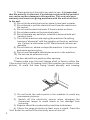
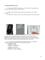
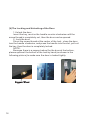
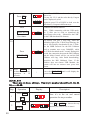
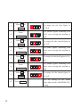
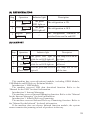
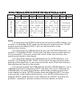
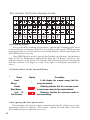
Please read the instruction
manual carefully before
use of the machine. Keep
this manual handy for
future reference.
Refrigerated Vending Machine
RAM 4000
(AVM - BA48)
Instruction and Operations Manual
Recommended Location:
This Refrigerated Vending Machine
Should Be Operated Indoors.
Manufacturer:
Automated Vending Technologies, Inc.
TABLE OF CONTENTS
VENDING MACHINE
Important Machine Placement Criteria and
Warranty Information
……………………………………………………1
Unpacking and Installation Instructions
……………………………………………………4
Programming Instructions
……………………………………………………8
Operating Instructions
……………………………………………………11
How to Operate the Remote Control
as an Owner
……………………………………………………18
The Daily Maintenance of the Vending Machine
……………………………………………………37
Quick Troubleshooting Guide
……………………………………………………40
Vending Machine Schematics
……………………………………………………42
Quick Tray Changing Guide
……………………………………………………47
It is recommended that you fully review and follow all of
the information included in this manual to operate your
RAM 4000 to the fullest benefit possible. It is also
recommended that this manual be kept with the machine
at all times, in order to review proper service procedures
and parts requirements. You can also refer to our
website at: www.avtinconline.com for service video
demonstrations.
Should you have questions pertaining to this manual or
to your vendor, please contact your local AVT Distributor
or call us at 1.877.424.3663 or e-mail your inquiry to:
[email protected].
The Security Matters
Must Be Read Before Installation
Your safety and the safety of others are very important. We have
provided many important safety messages in this manual and on your
RAM 4000 Vending Machine. Always read and obey all safety
messages.
Warnings:
Opening, installation and the movement of the machine require
special technicians or people capable of moving heavy objects over
200 lbs. The opening, installation and movement must be done under
the guidance of technicians. Unsafe installation may carry potential
dangers of the machine tipping/falling over, getting electric shock,
fire disaster and serious injury. DO NOT ALTER THE MACHINE.
“ALTERING THE MACHINE VOIDS ALL WARRANTIES, AND
RELEASES AVT OF ALL LIABILITIES.”
Please do not service the vending machine by yourself. Always
have the assistance of a partner.
?
Reliable grounding:
"Grounding": Any setting in any location must have reliable
grounding.
1). Don't put the grounding near a gas pipe, water pipe, phone
loop, lightning rod etc.
2). There may be potential dangers if the grounding of the wires
are not complete.
?
Use correct electrical socket
"TO AVOID POTENTIAL FIRE HAZZARDS": DO NOT share the
socket with any other products.
?
1
1). Check polarity of the outlet you wish to use. It is important
that the polarity is checked. If a problem exists with the socket it
can cause serious damage to the machine. This can void your
warranty and create on-going problems with the unit at no fault
to the unit.
2). Do not tie the electrical cord or place it near heat or water.
3). Do not break or pull the electrical cord from the machine or
the socket.
4). Do not use the electrical parts if there is water on them.
5). Do not place water on the electrical parts.
6). Do not operate any switches, internal or external with wet
hands or tools.
7). Turn off the machine and unplug the machine if anything
becomes “abnormal” with the machine or the plug, switches
etc. Contact a technician or AVT Manufacturer as soon as
possible.
8). Do not climb on, shake or slope the machine. It can tip over
and cause serious injury.
9). Do not use flammable substances near or in the machine.
10). Do not use an extension cord.
The door should be in position after opening:
“Please make sure the limit linkage shaft is fixed in either the
1(Servicing Limit) or 2(Loading Limit) limit position (as shown in the
picture), to avoid the door being closed abruptly and causing
?
3
2
1
1). Do not touch the active parts in the machine to avoid any
unnecessary injuries.
2). Switch off the electricity source when changing the
fluorescent lamps to avoid shock or fire damage from
occurring.
3). Repairs should be conducted by machine technicians.
4). Check the surge protector at least once a month. Press the
“test” button to confirm if the electricity source turns off.
2
5). Check the fixed metal parts. Especially if there has been an
earthquake of a 5.0 or higher or after machine has been moved from
one location to another.
6). Check the electrical plugs regularly. It is suggested that they
are checked and cleared once a year.
3
I The Installation of Your New Vending Machine
(I)
Unpacking
(1) Remove packaging materials.
IMPORTANT: Do not remove any permanent instructions or the
data label on your vending machine.
Remove tape, fiberboard edge protectors and corrugated front
protector from your machine before using.
Do not use sharp instruments, rubbing alcohol, flammable fluids,
o r
abrasive cleaners to remove tape or glue. These products can
damage
the surface of your vending machine.
(2) Cleaning before use.
I M P O R T A N T: A f t e r y o u r e m o v e a l l o f t h e p a c k a g i n g
materials, clean the inside of your vending machine before using
it.
(II) Installation Requirements
(1) LOCATION:
The machine should be installed in shady, cool and dry location
indoors, try to avoid direct sunlight for extended durations of
time.
?
Avoid installing your machine near water. Make sure there is
e n o u g h r o o m t o o p e n t h e o u t s i d e d o o r. T h e d i s t a n c e
between the back of the machine and wall should larger than
12 in. to
ensure better air flow into the compressor.
?
INDOOR USE ONLY.
(2) HORIZONTAL POSITION
The vending machine should be installed on leveled and firm ground to
make sure the machine is in horizontal position (Refer to the following
picture), if not, there maybe some problems such as the door cannot be
opened or closed, after time, such a condition may cause distortion of the
body or cause damages to the inner structure. Please adjust the foot from
the front to the back and from the left to the right (Picture I).
4
Horizontal and Hard Surface
Slanted Surface
Multi-Level Surface
Swampy Surface
Picture I
(3) THE FIXATION OF THE BOTTOM
Make sure the reliability of the floor surface (The minimum area
is 43.5×41.3in.). While positioning, the detailed procedures and the
dimensions are as shown in the following pictures:
A) Place the bolts into the holes, which depth is 1.97in. Cover the
bolts with nuts when adjusting.
B) Remove the nuts and put the vending machine at a level
position.
C) As shown in Picture IV, position the bottom board to the foot
and the bolts, cover the mats and screw down the nuts with a wrench.
(4)ELECTRICAL POWER NEEDED
Refer to the nameplate of machine to determine the proper
voltage and frequency the machine requires(115VAC,60Hz,6.9Amp
circuit).DO NOT USE AN EXTENSION CORD.
5
27.5 in.
5.9
Position of foot
2.2 5.9
Bottom Kickstand
2.2
Position of foot
5.9
Position of hole
BACK
Bulgy Bolt
Position of hole
25.7
Vending Machine
Position of hole
Install Plane
2.2
2.2
Bottom Board
FRONT
Position of foot
5.9
Position of foot
Position of hole
26.1
Picture II
Picture I
Vending Machine
Vending Machine
Bottom Board
Hexagonal Nut
Elastic Pad
Even Pad
Hard Ground
Picture III
Picture IV
Note: a. The installation should be performed by trained technicians.
b. The maximum angle of the machine is 15° when installing and in
transit.
(5) PAY ATTENTION TO THE FOLLOWING MATTERS WHEN
INSTALLING THE VENDING MACHINE.
A) All electrical wiring must have a dedicated 120 VAC 20 AMP
circuit breaker. The vending machine must be plugged into its
own properly rated single phase outlet.
B) Keep the connector plug clear and make sure to plug it in its right
position to avoid fire hazzards.
C) Do not alter the grounding wire, and the wire cannot be connected
with the central heating pipe, gas pipe and some other wires.
D) Hold the connector plug while unpluggging the vending machine.
Do not pull the electrical wire.
E) Check the electrical wire carefully before using it. If it is damaged,
then it must be replaced by the special technicians.
F) When installed, please take effective measures to avoid tipping
the vending machine.
6
Grounding Socket
Grounding Port
Sketchmap of Indoor Grounding
7
II Working Principle and the Structure
The RAM 4000 Vending Machine from AVT, Inc. comes standard
with configurable trays and augers, especially designed for the
selling of snack goods and beverages with larger packaging. It has
an optional feature that can detect errors in the vending machine.;
the function of LED display ; It also has a large-scale display
window, a user friendly interface, all of which are easy for the
operator to use.The computer controller transfers the relative
information accordingly. The main-control system will send a signal
to the drivers to revolve the motor to release the goods. The goods
will be dropped to the delivery port directly. It can give the change
automatically or the user can use the give change knob to get the
change. We reserved a General Packet Radio Service (GPRS)
connecting port, specifically designed for VMS®, which is convenient
for long-distance management and control, and can be installed at
the clients request.
(I) Working Principle
Insert the coin/bill to the vending machine’s acceptor, the coin/bill
validator will recognize the value of the currency, then the user can
choose what to buy. The computer controller transfers the relative
information accordingly. The main-control system will send a signal
to the drivers to revolve the motor to release the goods. The goods
will be dropped to the delivery port directly. It will give the change, or
the user can use the return knob to get the change. You can do the
shopping easily in short time.
8
Flow Chart:
START
Coin Insert
Bill insert
Total Amount
KEY PAD
1
2
3
4
5
6
0
7
8
9
ENTER
CLEAR
Change
Delivery Bin
Change
Return Knob
Change outlet
END
Change Return
9
(II)Structure
Display Door
Display
Key Pad
Lock
Bill Validator
Coin Insert
Return Knob
Change Return
Delivery Bin
10
III Operating Instruction
In order to ensure successful daily operation of the RAM 4000
vending machine, the owner should operate the machine per the
following instructions: Run every driver once by pressing "sale
test"on the remote, then “set start” to ensure the motors are on their
correct initial positions .
Then check the position of the augors to make sure they can
reach the following standards:
1.SINGLE AUGERS:
A). When the width of the snack is less than the inner diameter
of the augers and bigger than 1.9 in., the front end of the
augers should be at the lowest position of the tray.(A little to
the left as shown in Picture I)
B). When the width of the snack is no less than the inner
diameter of the augers, the front end of the augers should be
turned 1/8 clockwise on the basis of 1).(As shown in Picture
C). When the width of the snack is no bigger than 1.9in., the
front end of the augers should be turn 1/8 counterclockwise on the basis of 1).(As shown in Picture I)
Initial position
for beverage tray
Double augors
Initial position
Initial position 2
Initial position 3
Picture II
Initial position 1
Picture I
If the initial position of the augors cannot reach the above
standards,please adjust it as the following steps:
1. Pull out the chuck of the augors and adjust the angle (As shown in
Picture II) until the front end of the augors can reach the above
standards.
2. Put the drivers to their original positions. Please make sure the
augors line up with the chuck.
11
Augers Drivers
Tray
Augers
Tray No. and Price Tag
Tray Divider
Picture III
(I) LOADING THE PRODUCT INTO THE TRAY
The trays are tiltable. The tray will tilt down and stop at the limit
position.(As shown in the Picture III ).
?
After loading products, lift the tray gently and push it into the
machine to make sure the tray has reached its correct position,
and connects to the interior plug.
?
After loading, confirm the prices are programmed and set on
the scrolling price tag.
?
NOTE:
a. Fill each tray entirely with products, if not, at least make sure
to fill the tray from back to front.
b. The products should be with cubic packaging, and any fragile
products are not recommended.
c. Put the products in upright position without any slant.
d. DO NOT stand on the vending machine while loading or
conducting other maintenance services.
e. Ensure the augers are in home positions. Don't take them out
and move them at will while loading products or at any time.
12
(II) ADJUSTING THE SCROLLING PRICE TAGS:
Adjust the price tag to the desired number, which must be in the
middle of the display, scroll the price tag from the top to the bottom.
Tray No. and Price Tag
Wheel for the Tray No.
Wheels for the Price Tag
Axis
(III) INSTALLATION AND INSTRUCTION FOR THE BILL/COIN
If not provided by AVT. Please refer to the owners manual for
these products.
(1)The fixation of the Bill/Coin Validator:
Screw off the four nuts of the Bill Validator, attach the Bill
Validator to the door, replace and tighten nuts.(Picture l).
Remove the three bolts on the face plate of the inner vending
machine door, lower the face plate on the Coin Mechanism, align the
three holes in the right position with the bolts hole, then screw on the
three bolts. (Picture ll).
Picture l
Picture ll
Picture lll
13
(2)CONNECTION INSTRUCTIONS:
Prepare a validator wire with three terminals
(two are the same, the third one is different). For the
two terminals, one is connected to the bill validator,
the other is useless. The third terminal is connected
to the reserved point on the machine(Picture lll).
Finally, take the wires from the right of the bill
validator, go down through the bottom of the display,
tie up the wires at the corner.
The wire from the coin mechanism is connected
to the reserved point on the machine(Picture lV).
Finally, tie up the wires in order at the left of the coin
mechanism, then put them into the wire groove.
14
Picture lV
(IV) MACHINE START-UP
1). Press the RESET button once. This button is located at the
bottom right hand corner of the cabinet.
3). Make sure that the open and close switch is in the “open”
position.
4). Take the remote control off the door and press the “lamp” key:
5). Load snack trays with product. Make sure the door is opened
and set to the full open position. Grab the center of tray, tilt up
slightly, pull forward, tilt down and slide tray out until it stops; then
allow the tray to tilt down (the tray will not fall out) for easier loading.
Only one shelf should be in the loading position at a time.
6). To operate the RAM 4000 vending machine to its highest
capacity, we recommend the following sized items:
a) ROW 1: Chips
b) ROW 2: Candy
c) ROW 3: Sandwiches
d) ROW 4: Cookies
e) ROW 5: 12 oz. Cans
f) ROW 6: 16-20 oz. Bottles
15
(V)The Locking and Unlocking of the Door
1.Unlock the door
Insert the key, revolve the handle counter clockwise until the
screw thread is completely out, then the door can be opened.
2? Lock the door
Direct the screw thread at the center of the lock , close the door,
turn the handle clockwise, and press the handle into the slot, pull out
the key, then the door is completely locked.
NOTE:
Because there is a support-wheel for the door at the bottom,
please upthrust the bottom of the lock by hand (as shown in the
following picture) to make sure the door is locked tightly.
Support-Wheel
16
IV LED Display Screen Instructions
BILL IS OUT OF USE
LACK OF RESERVE
IN RETAIL
$
The LED display screen has three (3) different functions:
1). In Retail. The Green light for retail indicates the machine is in
use and able to conduct transactions. If this option is not lit up,
please consult trouble-shooting portion of manual.
2). Bill is out of Use. The red light for the Bill Validator suggests
that the cash box is full or there is something wrong with the bill
validator. If the red light in the insert port is lit, use of the bill validator
will be hindered until cash box is emptied.
3). Lack of Reserve. If the red light for the lack of reserve light is
on, this indicates there is not enough change in the coin mechanism.
Re-fill the coin mechanism to resolve the problem.
17
V. INSTRUCTION OF KEYBOARD
(I)The proper use of remote control style keyboard for the
RAM 4000
1.Function Introduction
The operator can control and examine
the vending machine by using the
attached remote control to set the price,
clock etc. While in setting mode, the
operator can set all the parameters by
the remote control. The remote must
remain attached and hard wired to the
control board at all times. Failure to
maintain remote control integrity to the
control board will void warranty for this
item. Please handle with care.
DOWN
CHL SET
MODE/STOP
The appearance of the Keyboard is
shown to the right:
18
UP
FINISH
PRICE
SALE STAT
SET/START
GROUP
SALE MODE
L ROOM
LAMP
SALE TEST
ERR
R ROOM
Operation Instructions
(1) Sales Statistic
Step
1
Operations
Display
Description
Press
1. “TL” represents the total amount of the products.
2. “1234560” is the real number. The two items are
displayed cycled.
SALE STAT
Once.
1. Press UP or DOWN to choose the tray you’d like
to see. 2. The tray No. CL11 and the sold number
can be displayed cycled.
3. Repeat to press UP or DOWN to look over the sold
number in different trays.
4. When the chosen tray No. does is be set, it will
display “0000”.
2
Press UP or
DOWN
3
Press
1.“GL” represents the total amount of the money.
2. “123456.5”is the real number. The two items are
displayed cycled.
SALE STAT
Twice.
1. Press UP or DOWN to choose the tray you’d like to
see.
2. The tray No. CL11 and the sold number can be
displayed cycled.
3. Repeat to press UP or DOWN to look over the sold
number in different trays.
4. When the chosen tray No. is not set, it will display
“0000”.
4
Press UP or
DOWN
5
Press
CARD
SALE STAT
Three times.
Press UP or DOWN to choose the tray you’d like to
see.
The tray No. CL11 and the sales data by Card can be
displayed cycled.
Repeat to press UP or DOWN to look over the sales
data by Card in different trays.
6
Press UP or
DOWN
7
Press
SALE STAT
1. “CARD” means the sales amount statistic from the
Card Reader.
2. “12345.65” is the sales data from the Card Reader,
"CARD" and the data are displayed cycled.
FREE
1. “FREE” means the sales statistic of the Coupon.
2. “12345.65” is the sales data by Coupon; "FREE"
and the data are displayed cycled.
Four Times.
19
Press UP or DOWN to choose the tray you’d
like to see.
The tray No. CL11 and the sales data by Coupon
can be displayed cycled.
Repeat to press UP or DOWN to look over the
sales data by Coupon in different trays.
8
Press UP or
DOWN
9
Press
USB data download function:
Note: While connecting with the USB mode,
the U disk can be used to download the
data.(Please refer to the “Manual for the USB”
for the USB download file format)
SALE STAT
five times.
The buzzer will give a long ring, when the
indicating light of the U Disk stop flikering, the
data is successfully downloaded to the U Disk.
(As the MDB Protocol for the Bill Validator
need to examine once every 500MSEL, while
the U Disk download need 1 second. During this
period, the connection between the Bill Validator
and the Main Control will be cut and the Bill
Validator will ring. After finish downloading,
reposition the Bill Validator) Note: If the
machine does not choose USB Module, the
system will has no answer once press this
button.
10
Press
SET/START
11
Press FINISH or
without
any
operation
in
20
seconds
/
Leave the SALE STAT, and it will display the
system time.
(2)CHL SET
There are six lines of trays. The tray's number should be 11-18, 2128,……61-68.
Step
Operation
Press CHL
1
SET
Press
UP or
2
DOWN
20
Display
Description
Now it’s in the set and cancel
operation for trays number.
Press UP or DOWN to choose the tray
number you’d like to set or cancel.
Cancel the Set.
3
Press SET/START once
After canceling the set
the
tray’s number will flicker.
Saving the Set.
4
Press SET/START twice
After saving the set the tray’s
number will stay solid.
Press SET/START three
5
Repeat the operation of step 3.
times
Press FINISH or without
6
Leave the CHL SET
and it
/
any operation in 20 seconds.
will display the system time.
(3)PRICE SET
Step
Operation
Display
Description
Now it is in the Price Setting Mode.
1
Press PRICE
Setting the Different Prices
Note:
Press
UP
The
number
is
increased
or
or
decreased on the basis of the minimum
2
DOWN
number that the Coin Mechanism can
recognize, the range is $0.00-$12.50
21
3
Choose No. 11 tray. Note: When the
chosen tray No. does not set, the
system will work but the operation
cannot be saved.
Press the keyboard to
choose
the
tray
number. 11
Press
ENTER
Press ENTER The price for No. 11
tray can be set for the desired amount.
Press CANCEL
select the tray
number.
or
4
CANCEL
5
Press FINISH or
without any operation
in 20 seconds.
6
Press PRICE Twice.
7
Press FINISH
8
Press PRICE Three
times.
Leave the price set, and it will display
/
the system time.
/
It is in Return Coins Mode.
0.05
9
22
Press UP or DOWN
Filling the Coin Mechanism Mode
Fill the coins to the top in the
mechanism & it will display the
inserted amount.
Fill coins successfully, and it will
display the system time.
Press Up or DOWN to
choose the coin to test
dispense.
0.05
0.10
0.25
10
The selected coin pipe will begin to
return coins until you press the
Press SET/START
FINISH button.
11
/
Press FINISH
Exit The Return Coin Mode, and it
will display the system time.
(4)SALE TEST
Step
Operation
1
Press SALE TEST
Waiting for the Delivery Test
Press
Choose the tray number you’d like to
UP
Display
or
Description
2
DOWN
test.
1. Tray 13 will give a delivery once.
2. Press SET/START once
3
it will give a
delivery.
Press SET/START
3. Press SET/START twice, the tray will
give delivery continuously.
4
Press FINISH
/
Leave SALE TEST condition and it will
display the system time.
5
Press SALE TEST
The delivery condition will be recycled.
6
Press SET/START
Every tray can give a delivery from
CL11-CL68. When the chosen tray No. is
not set, the system will also work but the
tray doesn’t act.
7
Press FINISH
/
Exit the SALE TEST position
and it
wwill display the system time.
23
(5)Malfunction Inquiry
Step
Operation
Press
ERR
1
Once
Press
ERR
2
Twice
Display
Description
“Good” or the
malfunction
code of display
system,
Bill/Coin
Validator.
1. Display “Good” while the system
is normal.
2. With malfunctions, it will display
EA, EB, EC (System, Bill
Validator, Coin Mechanism. )
“Good” or the
tray number
with
malfunction.
1. Display “Good” while the system
is normal.
2. With malfunctions, it will display
CL11~CL68 (the malfunction
with the tray motor or there’s a
jam.)
3
Press
ERR
Three times
This operation is the preparation for
clearing all of the tray’s malfunctions.
4
Press
SET/START
Do this step to clear all the trays
malfunctions.
5
Press FINISH
or without any
operation in
20 seconds.
/
Press
ERR
Four times
“Good” or the
system
malfunction
code.
6
Note:
Exit and it will display the system
time.
Repeat steps 1
3 to review and clear
the malfunctions.
1. If the machine is equipped with the Vend Sensing System (VSS), it will
automatically detect if the product vended properly.
2. If the motor driving the augor has malfunctioned, the motor cannot turn.
It will report a tray malfunction, and the machine will stop vending until
the malfunction is repaired and the Remote is used to clear the
malfunction.
24
(6)SET SELLING WITH AWARD
Step
Operation
1
Press SALE MODE
Once.
2
3
Display
It is in Force Vending Mode
or
Press UP or DOWN
Press FINISH
for 20 Seconds
FC N means it is not in Force
Vending Mode; while FC Y
means Force Vending Mode.
/
Save the above operation and
quit SALE MODE and it will
display the system time.
*****
Release the above operation
and exit SALE STAT and it
will display the system time.
Without Operation
4
Description
25
(7) PARAMETER SET SYSTEM CLOCK
Step
Operation
Display
Description
Press
1
MODE/STOP
It is in the system clock setting mode.
Once.
1. Now you can set the year.
Press
2
2. The four figures flickering mean
SET/START
the year can be set.
Press UP or
The range of the year can be from
3
DOWN
Press
2000 to 2099.
Now you can set the month and save
4
SET/START
the year’s setting.
Press UP or
5
The range of month is 1 12.
DOWN
Press
Now you can set the date and save the
6
SET/START
month’s setting.
Press UP or
The range of the date is 1-31
7
DOWN
26
February is 29
Press
Now you can set the hour and save the
8
SET/START
date’s setting.
Press UP or
9
The range of hour is 0-23.
DOWN
Press
Now you can set the minutes and save
10
SET/START
the hour’s setting.
Press UP or
11
The range of the minutes is 00-59.
DOWN
Leave the Clock Set Mode and save
12
Press FINISH
/
the minutes setting, and it will display
the system time.
27
ENERGY-SAVING
Step
Operation
Display
Description
Press
Now it is in ENERGY-SAVING
1
MODE/STOP
Mode.
Twice
The
three
figures
flickering
Press
2
together, means that the OFF time
SET/START
for the energy-saving can be set.
Press UP or
Set the range:0 00 23 30
use
3
DOWN
30 minutes as a unit.
The three figures flickering
together, means that the ON time
can be set and save the OFF time
setting.
Press
4
SET/START
Press UP or
Set the range: 0 00 24 00 use
5
DOWN
6
28
Press FINISH
30 minutes as a unit.
/
Save the setting for ON time and
exit ENERGY-SAVING mode, and
it will display the system time.
LAMP TIME
Step
Operation
Display
Description
Press
Now you can set the ON/OFF
1
MODE/STOP
Mode of the lamp.
Three times.
Press
The first figure flickering enables
SET/START
you to set the ON time of the hour.
Press UP or
The range is 0 23 take one hour
2
3
DOWN
Press
4
SET/START
Press UP or
as a unit.
The last two figures flickering, now
allows you to set the ON time for
the minutes, and save the setting for
hour.
The range is 00
59, use one
5
DOWN
Press
6
SET/START
Press UP or
minute as a unit.
The first figure flickering allows
you to set the OFF time of the hour,
and save all the settings for the ON
time.
The range is 0 23
use one hour
7
DOWN
Press
8
SET/START
as a unit.
The last two figures flickering,
allows you to set the OFF time for
the minutes, and save the settings
for hour.
29
9
10
Press UP or
DOWN
The range is 00
minute as a unit.
59, use one
/
Save the settings for the OFF time
of minutes and leave LAMP setting
mode, and it will display the system
time.
Display
Description
Press FINISH
REFRIGERATION TEMP
Step
Operation
1
Press
MODE/STOP
Four times.
Now you can set the refrigeration
temperature.
6
The displayed number is the
temperature set by the last service.
Note: The unit for the set
temperature is Centigrade.
20
Set the desired temperature. The
temperature range is 6 ~ 25º C
(42.8 ~ 77ºF).
Press
2
SET/START
Press UP or
3
DOWN
The cor r espondi ng sheet bet ween ¡ æand ¨ H
:
¡ æ
6¡ æ
7¡ æ
8¡ æ
9¡ æ
10¡ æ
11¡ æ
12¡ æ
13¡ æ
14¡ æ
15¡ æ
¨ H 42. 8¨ H 44. 6¨ H 46. 4¨ H 48. 2¨ H 50¨ H 51. 8¨ H 53. 6¨ H 55. 4¨ H 57. 2¨ H 59¨ H
¡ æ 16¡ æ
17¡ æ
18¡ æ
19¡ æ
20¡ æ
21¡ æ
22¡ æ
23¡ æ
24¡ æ
25¡ æ
¨ H 60. 8¨ H 62. 6¨ H 64. 4¨ H 66. 2¨ H 68¨ H 69. 8¨ H 71. 6¨ H 73. 4¨ H 75. 2¨ H 77¨ H
30
4
Press FINISH
/
Save the setting
REFRIGERATION
condition.
and
leave
TEMP
NOTE:
(1) IF THE TEMPERATURE GOES ABOVE THE SET POINT, THE
VENDING MACHINE WILL GO OUT OF RETAIL.
MACHINE NUMBER
Step
Operation
Display
Description
Press
Now you can set the machine’s
1
MODE/STOP
number.
Five times.
Press
The first figure flickering means
2
SET/START
that the figure can be set.
31
Press UP or
The range for the first figure is
0-9,A-F.
3
DOWN
The second figure flickering will
allow you to assign the machine a
digit.
Press
4
SET/START
Press UP or
The range for the second figure is
0-9, A-F.
5
DOWN
SET/START
The third figure flickering will
allow you to assign the machine a
digit.
Press UP or
The range for the third figure is 0-9,
Press
6
7
A-F.
DOWN
SET/START
The fourth figure flickering will
allow you to assign the machine a
digit.
Press UP or
The range for the fourth figure is
Press
8
9
0-9, A-F.
DOWN
10
32
Press FINISH
/
Save the setting for the fourth
figure and exit the MACHINE NO.
setting.
(8) REFRIGERATION
Step
Operation
Indicator light
Press L ROOM
The green
once
LED light on.
Press L ROOM
The green
twice
LED light off.
Repeat
press
/
L ROOM
1
2
3
Description
The refrigeration is ON.
The refrigeration is OFF.
The refrigeration condition is
switched between On and OFF.
(9) LAMP SET
Step
1
2
3
Operation
Indicator light
Description
Press LAMP
Once
Press LAMP
Ttwice
Press LAMP
Three times
The green LED light on
while the red LED light off.
The green LED light off
while the red LED light on.
Both the green and red LED
light off.
The lamp will be on all
the time.
The lamp will be on or
off as set.
The lamp will be off
all the time.
This machine has reserved/optional module, including GPRS Module,
USB Module and IR Delivery Examine Module.
Introduction 1: USB Module
The machine reserved USB data download function. Refer to the
“Manual for the USB” for detail information.
Introduction 2: Internet Managing
The machine reserved Internet Managing function. Refer to the “Manual
for the Internet Managing” for detail information.
Introduction 3: Infrared Delivery Examining
The machine reserved Infrared Delivery Examining function. Refer to
the “Manual for the Infrared” for detail information.
If the machine does not choose Infrared function module, the system
cannot examine the jamming or lack of products in the tray.
33
Malfunction Content List of AVM-BA48( Vending Machine):
Malfunction
Content
GOOD
EA01
EA02
EA03
EA04
EA07
EA08
EB01
EB02
EB03
EB04
EB05
EB06
EC01
EC02
EC03
EC04
CLXX
Malfunction description
The machine is working well. (There is no malfunction with the
vending machine.)
There is communication malfunction with the driving board.
There is communication malfunction with the GPRS mode.
There is something wrong with the system clock.
There is something wrong with the freezer system. 1 There is
something wrong with the sensor. 2 The compressor will shut
down after 24 hours. It appears have EA04 fault, but when
testing the temperature sensor which is no problem, the EA04
fault disappeared, but the compressor still stop working.
There is communication malfunction with the USB mode.
Card Reader Communication Error.
The bill validator is not responding.
The cash box has been removed. REFER TO NOTE
The cash box is full.
There is something wrong with bill validator sensor.
There is something wrong with the driving motor of the bill
validator.
A bill is jammed in the validator.
The coin mechanism is not responding.
There is jam while receiving coins.
There is jam while disbursing coins.
There is something wrong with the coin mechanism sensor.
Motor Malfunction 1.Tray Motor Malfunction 2.Tray May Be
Jammed)
NOTE:
When the cash box is removed, some Bill Validators do not send signal to the
control board, so it will not display EB02 for some Bill Validators.
34
NOTE: THE MALFUNCTIONS WITH THE OPTIONAL PARTS :
Optional
Parts
USB
No
GPRS
Yes
Malfunction Display
It will display
EA07,
however,
the GPRS system
does not display
such malfunction.
The machine will
work in this mode.
USB
GPRS
No
No
It will display EA02;
During the first two
minutes after startup
of the machine, it
can only have one
vend. After two
minutes the machine
will work in this
mode.
USB
GPRS
No
No
It will display EA02,
EA07. During the
first two minutes
after startup of the
machine, it can only
have one vend. After
two minutes, The
machine will work in
this mode.
USB
Yes
GPRS
Yes
It will display
GOOD, an the
machine will
work in this
mode.
Note:
(1) If choosing the GPRS module do not use the USB module. It is
normal if it displays EA07 when examining the malfunctions. GPRS
system does not display EA07, but you can see this in the
malfunction history.
(2) If choos i ng the USB Module do not use the GPRS Module, it is
normal if it displays EA02. During the first two minutes after startup
of the machine, it can only have one vend. After two minutes, the
machine will work in this mode.
(3) If choosing neither the USB Module nor GPRS Module, it is
normal if it displays EA02, EA07. During the first two minutes after
startup of the machine, it can only have one vend. After two minutes,
the machine will work in this mode.
(4) If choosing both the USB Module and the GPRS Module, it is a
USB malfunction if it displays EA07, please refer to the “Manual for
USB Module” to settle the problem, otherwise, please contact the
local dealer for help. GPRS system does not display EA07, but you
can see this in the malfunction history. It is GPRS malfunction if it
displays EA02, please refer to the “Manual for GPRS” to settle the
problem, otherwise, please contact the local dealer for help.
The contrast list for the displayed code:
(10) Loading Switch
Every time after loading the products, operate the loading switch once
to show that the loading has finished. According to the signal, GPRS internet
managing software will re-take account of the number, which can display the
lack information correctly.
Has GPRS Module or not, operate the loading switch once, the indicator
light will be lit. Meanwhile, although the light for “In Retail” is still on, the
machine cannot vend. After 120 seconds, the indicator light will extinguish
and the machine will begin to vend. (The light is telling the consumer to
wait.)
(11) Status Sheet for the Inserted Money
I
Status
Insert
Money
Needs
More Money
Lack Of
Coin Reserve
Display
/
Description
It will display the amount money that the
consumer inserted.
Flickering indicates that the consumer needs
to insert more money for the product desired.
Flickering, indicates the consumer needs to
use exact change
After opening the door, please note:
The machine will turn to remote control locked mode, if there is not any
operation within 30 minutes. The remote cannot be used then. Close the
door and then open it again to recover it.
36
V I Periodic Recommended Maintenance of your Vending Machine
It is necessary to conduct periodic maintenance on your
vending machine in order to keep it in the best working condition
possible. This will help extend it's life, and reduce repairs and
maintenance calls.
Details:
1). Keep the appearance clean. Every time the machine is serviced, it
should be cleaned by the route driver with a damp rag (do not wash!).
The glass inside and out should be cleaned with a glass cleaner.
2). The inside of the machine should be inspected and cleaned a
minimum of once a week. This allows for all functions to properly
work. Failure to keep the inside of the machine clean, may lead to a
unhealthy environment for your products and the functionality of the
machine.
3). If needed, clean the electrical parts by dry rag or soft brush.
(Clean only after machine has been disconnected from all electrical
outlets and components).
4). The delivery port becomes exposed to the environment and is
often utilized, it can easily become covered with dust. The delivery
port must be cleaned and checked regurarly.
5). Please refer to the owner's manual for proper care and cleaning
of the bill validator and coin mechanism.
6). Tray Maintenance Make sure the tray is balanced when being
pulled out or pushed in. The trays must be pushed in completely to
ensure electrical source will function and the tray will be properly
37
machine trays function properly.
7). Coinage Maintenance Periodic lubrication of the transmission
position will reduce friction to ensure flexible change giving process.
8). Key Press Maintenance Clean the key press regularly. Check the
keys to make sure they are working correctly. DO NOT CLEAN WITH
ACETONE, ALCOHOL OR ANY CORROSIVE COMPOUNDS!
9). Refrigeration System Maintenance In order to ensure that the
product which is vended from your machine is of suitable
temperature, it is necessary to keep the compressor, condenser,
evaporator and all other parts in the refrigeration system in good
working order. By visually checking and listening you can settle little
issues that may arise according to the sound, temperature and frost
condition. Avoiding future serious problems and reducing any
maintenance.
a). In order to assure the refrigeration system is running well, please
make sure the evaporator fan can run un-obstructed.
b). While clearing the condenser, please use a soft brush such as a
plastic brush (DO NOT USE A METAL BRUSH) to scrub the metal
vanes up and down. (As shown in picture).
c). Make sure the air path is accessible. Do not put anything near the
air path to ensure there will not be a blockage.
d). The water after defrost occurs must be drained from the drainage
funnel within 24 hours. There must not be puddling that occurs. This
may void your warranty. Please check regularly.
e). It will take over 5 minutes to restart the compressor if it is ever
shut down. Please be patient. Otherwise, the system may become
too hot or shut-off due to extensive pressure. Failure to wait for
compressor to initiate, may cause your warranty to become void.
Condenser
38
When Maintenance is Required on the Refrigeration Unit:
If maintenance is required on the refrigeration unit, this can be done
by following the steps below:
1). Remove the bolts on the seam of the delivery port and pull the
seam out.
2). Remove the bolts on the bottom board of the compressor unit and
make the compressor accessible for removal.
3). Pull out the refrigeration unit to the suitable position to conduct
maintenance.
To reattach reverse steps 1-3 above and go slowly.
39
Attachment I Quick Troubleshooting Guide
Before Calling for Service
If the machine appears to be malfunctioning, read though the manual first. If
the problem persists, check the common troubles and the solutions on the
following page. The problem could be something very simple that can be
solved without a service call.
TROUBLESHOOTING GUIDE
Troubles
NO
POWER
UNIT
WILL
NOT
ACCEPT
BILLS
UNIT
WILL
NOT
ACCEPT
COINS
40
Reasons
1. The socket doesn’t work.
2. The electrical plug is not in
its right position.
3. The button of the surge
protector is “OFF”
4. The fuse is bad.
Red
1. There is debris in
Lamp
the bill validator.
2. Cables are loose.
3. The bill validator is
damaged.
Green 1. Currency not
Lamp
accepted.
2. There is no product
in the machine.
3. Insufficient change
1. Incorrect Value
2. The coin is damaged/token
3. There is no product.
4. The indicator lamp doesn’t
light.
5. Cables are Loose
6. There is water in the coin
mechanism.
7. The coin mechanism is
damaged.
1.
2.
3.
4.
1.
2.
3.
Solutions
Power cut.
Make sure the plug in its right
position.
Turn the surge protector “ON”.
Replace the same size fuse
after cutting the power.
Clear the bill validator.
Re-install all the cables.
Replace the bill validator
1. Choose the right type of
currency.
2. Replace/add product.
3. Add sufficient coins.
1. Insert the right value.
2. Coin mechanism doesn’t
accept damaged coins or
tokens
3. Add product.
4. Check if the plugs are loose.
5. Check the transducer.
6. Dry it out.
7. Replace the coin mechanism.
Troubles
No product is
being delivered
when inserting
money.
The fluorescent
lamp doesn’t
light
Reasons
1. The money is jammed.
2. The products are sold out.
3. The product is jammed
during vend.
1. The fluorescent lamp is set
in the pattern of on/off. (It
is in “off” mode at this
time.)
2. The light bulb is broken.
3. There’s a problem with the
starter.
The fluorescent 1. The fluorescent lamp is set
lamp always on. in the pattern of on/off. (It is in
“on” mode this time.)
Solutions
1. Clear the jammed money.
2. Choose an alternate product.
3. Clear the jammed product.
1. Reset it by the remote control.
2. Replace the same size light
bulb.
3. Replace starter.
1. Reset it by the remote control.
NOTE:
All repairs should be performed by a qualified service technician who is
equipped with the proper tools and replacement components, using genuine
AVT parts.
41
42
TRAY
Breakdown Drawing for the RAM 4000 Vending Machine
REFRIGERATION
SYSTEM
CHEST
DOOR
Attachment II
VENDING MACHINE SCHEMATICS
43
Left Slide of
the Tray
Delivery
Port Parts
Chest Seam
Foot
Lower Hinge
Water Box
Power Supply
Plug Ports
Right Slide of
the Tray
Clapboard Ports for
Evaporator Room
Upper Left Side Board Port
Hinger for Evaporator Room
The Breakdown Drawing of Chest
Internal
Parts
Stainless Steel
Control Units
Double Paned
Glass
Display
Lock
Key-Pad
Bill Validator
Return Knob
Coin Insert
Change Outlet
Delivery Port
Stainless Steel
Delivery Port
The Breakdown Drawing of Door
44
45
Augers
The Breakdown Drawing of Tray
Tray Casing Seam
Spring Driver
Augers
Electrical Plug
Evaporator Fan-Cover
Evaporator
Evaporator Fan
Gas-Return Pipe
Vent-Pipe
Screw for Grounding
Condenser Fan
Water Box
Motor-Compressor
Condenser
Fan Trestle
Dry Filter
Bottom Board of Compressor
The Breakdown Drawing of
the Refrigeration System
46
47
Automated Vending Technologies, Inc.
Corporate Office:
341 Bonnie Circle, Suite 102 Corona, CA 92880
U.S.A.
www.avtinconline.com
[email protected]
Contact:
Toll Free 1-877-424-3663
Direct
1-951-737-1057
Fax
1-951-737-7646