1
Made in USA
Slim Line Rack UPS
User’s Manual
Models 3 & 4
www.mgeups.com
For service call:
1-800-438-7373
MGE UPS SYSTEMS
1660 Scenic Avenue
Costa Mesa, CA 92626
(714) 557-1636
www.mgeups.com
Revision A00
Revision History
Esprit Rack UPS User's Manual
86-153301-03
Copyright © 2000 MGE UPS Systems
All rights reserved. Printed in USA
New Release
10/00
Safety
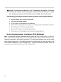
Important Safety Instructions. Save These Instructions.
This manual contains important safety instructions for the Esprit Models 3 and 4 that should be
followed during installation and maintenance of the UPS and Batteries.
Caution: Risk of electric shock, even with the unit disconnected from the AC power
source. Hazardous voltages still may be present through operation from the battery. The
battery supply should be disconnected by unplugging the battery cord from the UPS
when maintenance or service work inside the UPS is necessary.
The UPS and battery module contains voltages which are potentially hazardous. All repairs should
be performed by qualified service personnel only.
◗
Do not attempt to power the UPS from any receptacle other than a 2-pole, 3-wire grounded
receptacle for models 3 and 4.
◗
◗
To reduce the risk of fire, connect Esprit to a circuit provided with the following maximum branch
circuit protection in accordance with NEC, ANSI/NFPA70:
Model 3: 30 ampere branch circuit protection;
Model 4: 50 ampere branch circuit protection.
Do not place Esprit near water or in an environment of excessive humidity.
◗
Do not allow liquids or foreign objects to get inside Esprit.
◗
Do not block air vents in front, on top, or on bottom of Esprit.
◗
Do not plug any household appliances such as hair dryers into Esprit receptacles.
◗
Do not place Esprit in direct sunlight or close to heat emitting sources.
◗
The AC power receptacle should be near the equipment and easily accessible. To isolate Esprit
from AC input, remove the input cord from the AC power receptacle.
◗
Esprit contains lead-acid batteries that should be disposed of or recycled in accordance with
local applicable laws.
◗
Prior to installation, store Esprit in a dry location.
◗
Storage temperatures must be between -4° to +113°F (-20° to +45°C);
◗
Servicing of batteries should be performed or supervised by personnel knowledgeable of
batteries and the required precautions to handle high voltages. Keep unauthorized personnel
away from batteries.
◗
When replacing batteries, use the same number and type of batteries:
12 each, 12V - 5 Ahr.
• For model 3, use MGE P/N: 031-000003-0000
• For model 4, use MGE P/N: 031-000004-0000
~
: alternating current supply symbol
— : direct current supply symbol
: risk of electric shock symbol
i
Caution: Do not dispose of batteries in a fire. The batteries may explode. Do not open
or mutilate the batteries. Released electrolyte is harmful to the skin and eyes. It may be
toxic. A battery can present a risk of electric shock and high short circuit current.
The following precautions should be observed when working with batteries:
◗
Remove watches, rings, or other metal objects.
◗
Use tools with insulated handles.
◗
Do not lay tools or metal parts on top of batteries.
◗
Disconnect the charging power source prior to connecting or disconnecting battery terminals.
◗
Wear rubber gloves, boots, and safety glasses.
◗
Determine if the battery is inadvertently grounded.
◗
Please dispose of the packaging in accordance with applicable laws.
Federal Communication Commission (FCC) Statement
Note: This equipment has been tested and found to comply with Class A limits of Part 15 of the FCC
Rules. These limits are designed to provide reasonable protection against harmful interference when
equipment is operated in an industrial environment. This equipment generates, uses and can radiate
radio frequency energy and, if not installed and used in accordance with the instruction manual, may
cause harmful interference to radio communications. Properly shielded and grounded cables and
connectors must be used in order to meet FCC emission limits.
ii
Contents
Quick Start ..........................................................insert
Important Safety Instructions ....................................i
1. Introduction ........................................................1—1
MGE UPS Systems ......................................................................................1—1
Why the Need for Uninterruptible Power? ....................................................1—1
Theory of Operation......................................................................................1—1
Make Sure You Have the Following: ............................................................1—1
2. Getting to Know Your Esprit Rack UPS ..........2—1
2A. Product Features & Benefits ................................................................2—1
2B. UPS Model and Battery Identification
(dimensions/weights and part numbers) ..............................................2—1
2C. Esprit Rack UPS Product Views With Rack Kit ....................................2—2
3. Installation ..........................................................3—1
3A. Storing the UPS and Recharging the Battery ......................................3—1
3B. Unpacking the UPS ..............................................................................3—1
3C. Placement of the UPS ..........................................................................3—1
Rack Mounting ..............................................................................3—1
3D. Optional Accessories ............................................................................3—1
3E. Connecting the Optional Extended Battery ..........................................3—2
3F. Disconnecting the UPS & Battery to Take Out of Service ....................3—2
3G. Connecting to the Communication Ports ..............................................3—2
3H. Connecting the UPS to the Utility ........................................................3—3
3I. Connecting the Loads ..........................................................................3—3
3J. Solution-Pac Software ..........................................................................3—4
4. Startup and Shutdown ......................................4—1
4A.
4B.
4C.
4D.
4E.
UPS Startup ..........................................................................................4—1
Initial Startup Tests and Diagnostics ....................................................4—1
Battery Operation ..................................................................................4—2
UPS Shutdown......................................................................................4—2
Front Panel Display Functions ..............................................................4—2
LED Operation ..............................................................................4—2
Button Operation............................................................................4—4
4F. Fault Alarms ..........................................................................................4—5
5. Performance and Product Specifications........5—1
Sizing Guide and Battery Runtimes ..............................................5—2
Extended Battery Runtime ............................................................5—2
iii
6. Advanced Configuration ..................................6—1
6A. Entering/Exiting Configuration Mode ....................................................6—1
6B Using Configuration Mode ....................................................................6—1
6C Configuration Options ..........................................................................6—2
7. Service & Maintenance......................................7—1
7A. Maintenance..........................................................................................7—1
Maintenance Log ..........................................................................7—1
Places to Contact for Service and Questions................................7—1
7B. Recycling Your UPS ..............................................................................7—2
8. Troubleshooting ................................................8—1
Other Fine MGE Products ........................................................inside back cover
Figures
2a. Rear View of Models 3 and 4
With Rack Kit and Extended Batteries..................................................2—2
2b. Optional Rack Mounting Kit ..................................................................2—2
2c. Typical Front Views of Models 3, 4, Extended Battery, Label
Placement ............................................................................................2—2
3a. RS232, Contact Closures and Remote Shutdown................................3—2
3b. Communication Ports (USB and RS232 serial port) ............................3—3
3c. AC Line Cord of the Extended Battery ................................................3—3
4a. Front Panel Indicators and Controls......................................................4—1
Tables
3a. UPS Wiring Information ........................................................................3—3
5a. Esprit Models 3 and 4 Rack UPS Specifications ..................................5—1
iv
1. Introduction
Thank you for your purchase of the Esprit rack
"UPS" from MGE. The Esprit "UPS" will provide
many years of, trouble-free power protection for
critical high availability servers and other devices.
Please read this manual fully, to familiarize yourself
with the safety instructions and Esprit features.
MGE UPS Systems
MGE, one of the largest UPS manufacturers in
the world, has a power protection solution for
every power problem. Our product range includes
UPSs from 250 VA to over 4.5 MVA in single and
three phase configurations. Other products
include Power Management Software, DC to AC
inverters, line conditioners and isolation
transformers. Contact your sales representative
today for additional information about MGE’s
other fine products.
Why the Need for Uninterruptible
Power?
Servers and other electronic devices do not store
sufficient energy to overcome the power outages
and short interruptions that occur on a daily basis.
Any interruption of the utility power may stop the
operation of a computer and cause loss of data,
potential hardware damage, and inconvenience.
A "UPS" is an uninterruptible power supply. The
UPS has an internal battery to provide power
back-up if the utility power is lost or a short outage
occurs. In addition, the Esprit UPS provides surge
protection from indirect lightning strikes, power
surges and short high voltage transients (spikes)
created by machinery or other common equipment.
Theory of Operation
Esprit normally operates in the bypass mode.
Surge suppression and filtering are also provided
in this mode.
The UPS instantly transfers the load to the battery
when a power failure occurs. If the power returns
before the battery is exhausted, the operation
returns to normal and the battery is recharged.
The Esprit UPS is comprised of three major
systems: the inverter, the battery/battery charger
and the bypass.
All logic and supervision in the UPS is provided by
a state-of-the-art micro-controller.
Inverter
The inverter is the heart of the UPS and inverts
direct current (DC) from the battery into
alternating current (AC) at 120 volts. The DC voltage
from the batteries is converted into a pseudo-sine
wave by a pulse width modulated (PWM) inverter.
This unique MGE technique, eliminates all bulky
60 HZ components, reduces heat, and greatly
enhances reliability.
Battery
The battery provides the energy source for back-up
when a power failure occurs. The battery is a
recombinant, sealed, lead acid-type battery which
provides the high current required for UPS use
and long life. It requires no addition of water during
its life.
Battery Charger
The battery charger maintains the battery. The
battery charger converts 120 volt AC utility power
to filtered and regulated DC current specific for
battery charging.
Bypass
The bypass is the electro-mechanical hardware
providing a transfer to or from the inverter. This is
done rapidly and synchronized to the utility power
sine wave in order to provide continuity to the critical
device and not cause a re-boot.
Make Sure You Have the Following:
◗
◗
◗
◗
◗
◗
Esprit Rack UPS
Solution Pac CD ROM
Cables (RS232 & USB)
Quick Start Guide
Stabilizing Feet (2)
Mounting Screws & Nuts
MGE P3 Policy
Warranty Card
◗ Warranty Statement
◗ Esprit Label
◗ Rack “ears” (2)
◗
◗
1—1
1—2
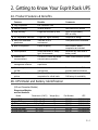
2. Getting to Know Your Esprit Rack UPS
2A. Product Features & Benefits
Features
Benefits
◗ Plug in operation
Comments
Low installation cost
◗ Modular concept
Greater flexibility
Add batteries as needed
◗ High efficiency
Longer life and back-up time
Up to 93% on battery,
98% on utility
◗ 2/3 components reduction
Longer life, higher reliability
Unique MGE design
◗ Many user selectable
parameters
Tailor the UPS to
environment
Front panel button accessible
◗ Built-in receptacles
Easier to specify
Most common NEMA
receptacles are included
◗ Quiet operation
Allows placement in "library
type" environments
Small fan only runs while in
battery mode
◗ Standard HID
communications
Provides the latest and fastest
communications possible
Other communications optional
◗ Network-based power
management software
Multiple server shutdown and
supervision
◗ Web management
via XML
New standard for web
management
Easier to use than HTML and
provides additional features
◗ Extended distribution
options
Provides additional
receptacles for critical loads
Optional
Call factory for availability
2B. UPS Model and Battery Identification
(US and Canadian Models)
Dimensions/Weights
and Part Numbers
Model
Esprit 3 SLR
Esprit 4 SLR
SLR Extended Battery
Rack rail kit
AS/400 DB9 cable
AS/400 DB15 cable
Dimensions (H W D)
Weight (lbs.)
Part Number
UPC
5.25 x 17 x 20
5.25 x 17 x 20
5.25 x 17 x 20
5 x 5 x 17
12 x 12 x 1
12 x 12 x 1
75
75
60
6
1
1
ESP030
ESP040
ESP001
ESP104
ESP105
ESP107
635760894318
635760894455
635760894004
635760894042
635760894059
635760894073
2—1
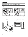
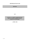
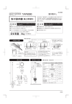
2C. Esprit Rack UPS Product Views With Rack Kit
Figure 2a. Rear View of Models 3 and 4 With Rack Kit and Extended Batteries
Model 3
Model 4
COM1
USB
CAUTION: Batteries inside. Risk of electric shock even when input
power is removed. Do not remove cover. No user serviceable parts inside.
Refer to qualified service personnel.
Utilization en atmosphere controlee
Intended for use in a controlled environment
Utilización preuista en un amblento controlado.
COM1
SW4
USB
15A/120Vac
15A/120Vac
Overload
protection,
push to reset
Overload
protection,
push to reset
15A/120Vac
15A/120Vac
Vdc In/Ue/Entrada
Do not disconnect under load
Do not disconnect under load
15A/120Vac
15A/120Vac
Vdc In/Ue/Entrada
Vdc In/Ue/Entrada
Overload
protection,
push to reset
Overload
protection,
push to reset
144Vdc / 4 Amp hr.
Continuous amps: 25
144Vdc / 5 Amp hr.
Continuous amps: 33.3
Vdc Out/Us/Salida
Intended for computer loads only
ATTENTION: Contiant batteries. Risque de choc electrique milime apreis
deparition tanaion d entrada. Ne pas enlevar le capot. Absence de piécede
recharge à l'intérievr de l'appareil. Appeler personnel de meinlenance qualifié.
Vdc Out/Us/Salida
Intended for computer loads only
Vac
In/Ue
Eing/Entrada
ATTENTION: Contiant batteries. Risque de choc electrique milime apreis
deparition tanaion d entrada. Ne pas enlevar le capot. Absence de piécede
recharge à l'intérievr de l'appareil. Appeler personnel de meinlenance qualifié.
Vac
In/Ue
Eing/Entrada
Do not disconnect
under load
Out/US
Ausg/Salida
CAUTION: Batteries inside. Risk of electric shock even when input
power is removed. Do not remove cover. No user serviceable parts inside.
Refer to qualified service personnel.
Utilization en atmosphere controlee
Intended for use in a controlled environment
Utilización preuista en un amblento controlado.
SW4
Vdc In/Ue/Entrada
Do not disconnect
under load
In/Ue
Eing/Entrada
Out/US
Ausg/Salida
144 VDC
Amp hr: 5
Continuous Amps: 33
In/Ue
Eing/Entrada
144 VDC
Amp hr: 5
Continuous Amps: 33
Extended Battery
Figure 2b. Optional Rack Mounting Kit
(ESP104)
Extended Battery
Figure 2c. Typical Front Views of Models
3, 4, Extended Battery, Label
Placement
!
Models 3 and 4
Extended Battery
Rack "ears"
(included)
mounting
screws & nuts
(included)
2—2
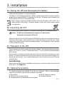
3. Installation
3A. Storing the UPS and Recharging the Battery
Always store the equipment in its original packaging.
The battery is of the sealed lead-acid type. Battery recharge requires that the battery module be
plugged into an energized NEMA 5-15 receptacle for 6-8 hours. The battery may be charged in the
box by pulling the AC cord out through the bottom.
Battery storage or prolonged shutdown should never exceed 6 months or 68°F (20°C), for a
battery initially at 100% charge. The battery warranty is void if the 6 month recharge interval
is not adhered to.
3B. Unpacking the UPS
It is recommended that the equipment be unpacked in an area close to its installation location.
Caution: The UPS and extended batteries weigh up to 75 pounds each.
Two people are required to lift the unit.
Remove the Solution-Pac CD, RS232 cable, and USB cable from the box and set aside for later use.
Fold the box flaps outward. Gently rotate the box on its side and slide the unit out of the box. Gently
rotate the unit upright and then remove the packing material. Save packaging for future shipment
of UPS to MGE for recycling.
3C. Placement of the UPS
Choose a location out of direct sunlight with adequate ventilation. The operating ambient temperature
range is 32° to 104°F (0° to 40°C). Temperatures above 77°F (25°C) should be avoided as battery
life is reduced.
Ensure that there is clearance around the intake vents in the front of the UPS and that the rear is unobstructed. Six inches of clearance at the rear of the unit is required. Units may be placed vertically or horizontally with zero clearance. Use the supplied stabilizing feet when vertically mounting the UPS and/or
extended battery.
Rack Mounting
Optional rack mounting hardware is available for rack mounting. Instructions for their use are included
in the rack kit. See Figure 2a.
3D. Optional Accessories
The following accessories are available for use with your equipment. Refer to each accessories'
manual for full installation, operation and maintenance instructions.
◗ Rack Rail Kit
◗ Multi-slot Communication Cabinet
◗ Extended batteries (no additional manual necessary)
◗ AS/400 Cables (for contacts)
◗ Extended distribution
3—1
3E. Connecting the Optional Extended Battery
Plug the DC battery cable into the UPS module as shown in Figure 2a. The cable plug is keyed,
so make sure to align the plug properly to the receptacle. Do not force the cable on, nor attempt to
reverse the connection. To do so, will damage the equipment and void the warranty. Plug the AC
line cord into an AC line receptacle. See Figure 3f.
3F. Disconnecting the UPS & Battery to Take Out of Service
Turn off the UPS module by depressing the “Off” red button if the “inverter on” or "utility power
present" (bottom LED) is lit. Unplug the AC line cord for the battery module. Unplug the DC battery
cord. For extended batteries unplug AC line cord and DC battery cord.
3G. Connecting to the Communication Ports
If you plan to utilize Solution-Pac HID ("human interface device" protocol), read the Solution-Pac HID
manual on the Solution-Pac CD for a full description of its features.
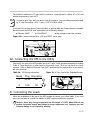
To connect to your computer, you will need the RS232 serial port or a USB (Universal Serial Bus)
port. The connection will be made between your computer’s serial or USB port and the serial or
USB port on the rear of the UPS module as shown in Figure 3d. Cables are supplied for this purpose.
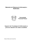
A slide switch is provided for either RS232 or USB communication. The slide switch (shown in
Figure 3d) is preset for RS232. Push the switch down for USB communication.
If communication does not operate, check the position of the slide switch.
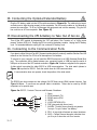
The RS232 port also contains two low voltage (24 VDC)/low current (5MA) contact closures. See
Figure 3d below. To use these an optional cable is available. These can be used by AS/400
computers or for special uses.
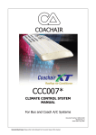
Figure 3a. RS232, Contact Closures and Remote Shutdown
9
OV
+8 to
+15VDC
8
7
OV
6
PNP
3—2
5
OV
4
3
2
1
RX
TX
1.
2.
3.
4.
5.
6.
7.
Open
RTXD transmit (TX)
RRXD receive (RX)
OPEN
LOGIC RETURN (OV)
PNP (plug and play, do not use)
ALARM - Contact closure through a transistor
from pin 7 to pin 5 when "low battery".
8. RPO - A logic high will activate an output shutdown.
9. INVO - Contact closure through a transistor from
pin 9 to pin 5 when the unit is on Inverter.
The transistor resistance is 27 ohms and the maximum current allowed is 140mA AC or DC with
ambient temperature of up to 40°C.
In order to get a "logic low" you have to limit the current to: logic low voltage required divided
by 27, logic low voltage = 0.5V. I max = 0.5/27=0.0185A=18mA.
If you intend to use other forms of communication, an optional Multi-slot Communication is available
that will convert the RS232 serial commands into the following formats:
◗ Ethernet, SNMP
◗ J-Bus/RS422
◗ High voltage/current relay contacts
Figure 3b. Communication Ports (USB and RS232 serial port)
RS232
Serial Port
Slide
Switch
COM1
USB
Port
USB
Utilization en atmospher
Intended for use in a con
Utilización preuista en u
SW4
Vdc In/Ue/Entrada
Do not disconnect under load
Vdc In/Ue/Entrada
3H. Connecting the UPS to the Utility
Plug the AC line cord of the UPS module into an AC 2-pole, 3-wire grounded receptacle for models
3 and 4. There should be no other loads on this branch circuit. To do so may result in a circuit
overload. Refer to National Electrical Code (NEC) specifications for requirements in your area or
ask your electrician.
Table 3a. UPS Wiring Information
Utilization en atmosphere controlee
Intended for use in a controlled environment
Utilización preuista en un amblento controlado.
Do not disconnect under load
Vac In/Ue/Entrada
144Vdc / 5 Amp hr.
Continuous amps: 25
G
4
5-50
50
CAUTION: Batte
power is removed. Do
Refer to qualified serv
Vdc In/Ue/Entrada
W
Plug Amp rating
L5-30
30
G
Model
3
Figure 3c. AC Line Cord of the Extended Battery
ATTENTION: Con
deparition tanaion d entra
recharge à l'intérievr de l
W
3I. Connecting the Loads
Utilize the receptacles on the rear of the UPS module to connect your critical loads. If you need
more, you may want to consider the addition of MGE's optional distribution extension.
Caution: Never plug a surge suppressor into the output of a UPS. Most UPSs do not
produce the proper output wave shape for surge suppressor use. Improper use and
resultant damage is not covered by warranty.
3—3
Caution: Connect only computer-type loads to the Esprit UPS. Warranty is void if noncomputer-type loads are connected to the UPS.
3J. Solution-Pac Software
Solution Pac software allows you to interface your computer with the UPS. The software is loaded
on your computer and through the communication port, can access and react to status information
from the UPS. Refer to the Solution Pac manual on the CD for a full description of its operation.
3—4
4. Startup and Shutdown
4A. UPS Startup
You are ready to start the equipment after installing the UPS module, optional battery module(s),
any options, and the communication cable (if used).
Follow these simple steps:
1.
Connect your computer equipment.
2.
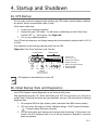
Depress the green "ON" button. You will hear an audible beep, and the “Utility Power
Present” LED "
" will be green. See Figure 4a.
3.
Turn on any computer equipment.
Your UPS has auto-frequency and voltage sensing and will automatically configure itself to 120, 50
or 60 Hz.
Your equipment is now receiving protected power from the UPS.
Figure 4a. Front Panel Indicators and Controls
Control Buttons
6 Status LEDs
1. Inverter ON
(UPS on battery power)
!
OFF
ON
Alarm 1. 2. 3. 4. 5.
Silence
6.
2.
3.
4.
5.
6.
Utility Power Present
Output Overload
Battery Charging Indicator
Replace Battery
Fault Detected
(Controls audible alarm
& alarm/fault handling)
LED operation is described fully in section 4E.
4B. Initial Startup Tests and Diagnostics
Your UPS will perform internal diagnostics as well as check utility power.
After depressing the green "On" button and starting your UPS for the first time, you will hear an
audible "beep" confirming the button has been depressed, and your UPS will perform the following
diagnostic tests:
1.
All front-panel LEDs will light, allowing visual confirmation that LEDs function properly.
2.
UPS will confirm the integrity of factory calibration settings. FAULT indicator illuminates
" ! " if internal settings have been corrupted.
3.
UPS will check utility input frequency and configure itself accordingly. If utility power is not
present, the UPS configures itself to run at the last frequency it detected in a previous
power-up operation.
4—1
If desired, the UPS can be set up to operate at a known, fixed frequency regardless of the
detected utility frequency. Fixed-frequency operation is often desirable in installations that
make use of cold-start capability. Discussion on this is in the Advanced Configuration Section
(section 6) of this manual.
If utility power is present and within specifications, your UPS will start up in bypass mode. Power
will be supplied to your computer loads and will be protected from a utility loss. The utility power
present, green indicator "
", will be lit.
If utility power is not present, your UPS will start on battery until utility power is restored. No
diagnostics will be performed in this case.
4C. Battery Operation
Battery Mode:
On
Utility power is outside specifications and computer loads are now powered
by UPS battery source.
Bypass Mode:
On
Utility power is present and within specification limits.
Inverter On Mode:
On
Flashes
Utility power is available but is outside specification limits.
Battery Low:
A low battery warning will sound. Acknowledge the alarm by depressing the
grey push button. Immediately save your work and shut down connected
computer loads to prevent data loss. The actual time to reach "low battery" can
vary significantly depending on the critical loads and condition of the batteries.
!
Flashes
4D. UPS Shutdown
At any time, your UPS may be shut down by depressing the "Off" red button. Make sure to hold the
button down for 2 seconds (prevents accidentally turning off your UPS). You will hear an audible
"beep" confirming the button has been depressed.
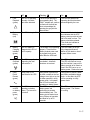
4E. Front Panel Display Functions
LED Operation
There are six status LEDs, arranged in a vertical column just above the control buttons. Icons
to the right of each indicator indicate the function. The status indicated by each LED is listed
below, in the order that they appear on the front panel (top to bottom):
4—2
1.
Fault
Detected
(yellow)
Off
Flashing
On
The UPS is operating
normally. No faults
have been detected.
The UPS has detected a
new operating fault. The
FAULT indicator will continue
to flash until the fault has
been acknowledged by
pressing the grey silence
alarm button.
The UPS has detected an
operating fault that has been
acknowledged by the user.
!
2.
Replace
Battery
(red)
The UPS battery is O.K.
3.
Battery
Charging
Indicator
(green)
The UPS battery is
charged within 80% of
its full capacity.
The charger is not operating
properly. Check that the
battery module power cord
is plugged into a source
other than the UPS itself.
4.
Output
Overload
(yellow)
The UPS is capable of
supporting the load
connected to it.
The UPS is heavily
overloaded. Automatic
shutdown is imminent.
5.
Utility
Power
Present
(green)
Utility power is not
connected to the UPS.
6.
Inverter
on/UPS
on battery
power
(green)
The UPS is not
operating on battery
power. The inverter is
turned off.
Utility power is present but
is either unstable or the line
voltage is too high or too low
to allow operation in utility
power mode. In this state,
the UPS will normally be
operating on battery power.
The UPS is operating on
battery power and
performing its periodic
inverter/battery test. The
battery test is started once
every 28 days of operation
and lasts for up to 60
seconds.
The result of the last battery
test indicates that the UPS
battery cannot provide at least
half of its rated run time. The
battery should be replaced.
This could also indicate an
inverter problem.
The UPS battery is not yet
fully charged and cannot
deliver its full rated run time if
a power failure occurs.
The UPS is slightly over-loaded.
The UPS will continue to support the load but it may not be
able to provide its full rated run
time if the UPS has to run on
battery power. Reduce the load.
Utility power is present, stable
and within acceptable voltage
limits. In this state, the UPS
will be operating on utility
power mode.
The UPS is operating on
battery power. The inverter
is running.
4—3
The "Fault Detected" LED turns on and acts as described above for ANY system alarm,
including those that have their own status indicators (e.g. overload, replace battery).
Button Operation
There are 3 buttons present on the front panel:
◗ The grey, "
" top button controls the audible alarm and alarm/fault handling.
◗ The green, "
" center button turns the UPS on.
◗ The red "
", bottom button turns the UPS off.
The internal microprocessor can directly read the state of the top (alarm silence) and bottom (power
off) buttons. The UPS is capable of distinguishing between a “short” and “long” depression and can
perform different actions based on how long a button or combination of buttons is depressed. A
“short” button press is defined as pressing and releasing a button within a 2-second time frame. A
“long” button press is recognized if a button is pressed and held for more than 2 seconds.
When a button is pressed, the UPS responds by beeping the horn. If the button is held down longer
than 2 seconds the UPS responds by beeping the horn again. The action assigned to a short button
press is carried out AFTER the button is released. Actions assigned to a long button press are carried
out immediately after the 2-second timeout, even if the button is not released after this time.
The UPS is capable of decoding six distinct “button states”:
1.
Short Top button press: Silences the alarm beeper if it is active. If a new alarm/fault is
detected after a silence operation, the beeper will be re-activated to issue the new alert. This
button sequence can be thought of as an "alarm/fault acknowledge" function. By pressing it,
the user acknowledges the presence of the then-active system alarms. After an acknowledge
sequence, any new alarms that occur will be brought to the user's attention by re-activating the
alert beeper.
2.
Long Top button press: Clears all active alarms and attempts to re-start the UPS on utility
power. If the UPS is already operating on utility power, or operating on inverter because utility
power is not present or not usable, then the alarms will be cleared but the restart-on-utility
request will be ignored. If the condition(s) that caused an alarm persist after alarm(s) are
cleared, the UPS will re-issue the alarm after a short delay.
3.
Short Bottom button press: No UPS activity is associated with this button combination.
4.
Long Bottom button press: Powers down the UPS. This is the "off switch". When the UPS
is powered down, neither utility or inverter power is provided to the load.
5.
Short Top + Bottom button press: The UPS will perform a battery test IF the UPS is running
on Utility power, and the battery is at least 80% charged (charger indicator on). If these two
conditions are not met, the test will be postponed until they are met.
6.
Long Top + Bottom button press: The UPS will enter configuration mode. In this mode,
various operational parameters may be changed by the user. To exit configuration mode, press
the top and bottom buttons again.
4—4
Although six button states are detectable, not every button combination has an assigned task. button
states/combinations that have no assigned task will simply be ignored.
The “Utility Power Present” does NOT reflect the state of the UPS output. If, for example,
the UPS has shut down due to an output overload, the Utility Power Present LED may be
solidly ON but the UPS output could be turned off (due to the overload).
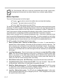
4F. Fault Alarms
LED Status
Audible Alarm Pattern
UPS Action
Fault " ! " LED flashes until
alarm is acknowledged or
cleared.
Low Run time Warning
(short-long-short beep)
Warning when there is less than
3 minutes of back-up time
remaining.
Fault " ! " LED flashes until
alarm is acknowledged or
cleared.
Low Battery Warning/Shutdown Occurs within 1 minute of UPS
(short-long-long beep)
shutdown. Could also indicate
a faulty battery charger.
Fault " ! " LED flashes until
alarm is acknowledged or
problem is corrected.
High Battery Warning
(short-short-short-long beep)
There is a problem with the
battery system.
Fault " ! " LED and Charge
"
" LED flashes until alarm
is acknowledged or problem
is corrected.
Charger Problem Warning
(long-short-long-short beep)
The battery system may not be
plugged into an AC source or
there is a charger problem.
Fault " ! " LED Battery Fail
"
" LED flashes until alarm
is acknowledged or cleared.
Battery/Inverter Test Failure
(long-short-short-short beep)
Indicates failed battery/inverter
test performed every 28 days.
Clear fault and recharge battery
for 8 hours. Manually initiate test
again. If fault recurs, call for
service.
Fault " ! " LED flashes until
alarm is acknowledged or
cleared.
Output Voltage Low
(on inverter,
short-long-short-short beep)
Output shuts down to protect
load from low voltage.
Fault " ! " LED flashes until
alarm is acknowledged or
cleared.
Output Voltage High
(on inverter,
short-short-short-short beep)
Output shuts down to protect
load from high voltage.
Fault " ! " LED and Overload
"
" LED flashes until alarm
is acknowledged or problem
corrected, flashes when
shutdown is imminent, and
solid if warning only.
Output Overload
Warning/Shutdown
(long-long-long beep)
Flashes when load exceeds
105%, solid when overload is
101-105%, automatically clears
when load is reduced.
4—5
4—6
5. Performance & Product Specifications
Table 5a. Esprit Models 3 and 4 Rack UPS Specifications
Item
Output VA
Output W
Surge protection, joule rating
Waveform
Nominal input voltage
Maximum input voltage (VAC)
Low voltage transfer (VAC)
Low line return (VAC)
High line transfer (VAC)
High line return (VAC)
Input current (A)
Input frequency (HZ)
Input protection
Transfer time
Overload protection, line mode
Overload protection, battery mode
Efficiency, on utility
Efficiency, on battery
Battery mode voltage
Battery life expectancy
Output frequency regulation
Battery mode output protection
Battery
Maximum charge current
Float voltage
Backup time
Battery protection
Recharge time
Battery charger ripple current
Low battery alarm level
Low battery shutdown level
Faulty battery alarm level
Low battery alarm level
Charger protection
Max. # of extended batteries
Controls
Communications
Temperature
Air flow
Humidity
Noise
Specification
2880/4000
2016/3150
420 joules per system
Stepped approximation of sine wave
120 VAC (opt. 100 or 127 VAC)
140
102
109
132
126
24/33 maximum
50 or 60 + or - 2.5 HZ
Customer provided, branch
4-8 ms.
Output disabled at >120% load
Output disabled at >120% load
>98%
>93%
120 VAC + or - 5% (120 VAC mode)
3-5 years
Nominal + or - 0.5 HZ
Electronic current limit
12 each 5 Ah
0.7 A
2.25 VDC/cell (162 VDC)
5 minutes
Current limiting fuses
8 hrs.. to 90%, 4 hrs.. to 80%
0.05C maximum
1.75 v/cell, no load (126 VDC)
1.65 v/cell, full load (119 VDC)
1.8 v/cell (130 VDC)
3 minutes before end of discharge
Overload, current protected
Unlimited
Start, stop, alarm reset switches
RS232 or USB + two contact
closures included
0-40 C
30 CFM on battery
0-95% non-condensing
45 dBA maximum
Comment
Each battery cabinet adds 210 joules
Pseudo-sine wave on back-up only
+10%, -15%
Adjustable to 96
Adjustable to 99
Auto-select at start-up
To or from battery
On battery
Self-protected
144 VDC nominal bus
With 100% discharge
100% load
1 internal, 1 w/extended battery
Full discharge
HID on RS232 or USB
(selectable RS232 or USB)
Heat: ESP030 40-141W
Heat: ESP040 60-211W
5—1
Table 5a. Esprit Models 3 and 4 Rack UPS Specifications (Continued)
Item
Design standards
Specification
Safety; UL, cUL 1778, Emissions;
FCC A, Surge protection; ANSI
C62.41, Transportation; (drop test),
IEC 68 level 1, (vibration), IEC
68.2-6 level 3, testing; PowerCet
tested
NEMA 5-30/50 w/ six foot cord
1 NEMA 5 30/50 and 4 5-15
1 each special female connector on
UPS (18" cord and male connector
on optional battery)
1 each (UPS, battery)
65/70 lbs.. total
200K hours
Input connection
Output connections
Auxiliary DC input
Size
Weight
MTBF
Sizing Guide and Battery Runtimes
Unix Server
PC Server
VA
Esprit 3 SLR
Esprit 3 SLR
+ 1 Ext. Batt.
Esprit 3 SLR
+ 2 Ext. Batt.
Esprit 4 SLR
Esprit 4 SLR
+ 1 Ext. Batt.
Esprit 4 SLR
+ 2 Ext. Batt.
Provides additional battery time
5.25" X 7.25" X 19"
(In minutes, 0.62 PF)
1
server
500
90
1
server
2
servers
1000
40
3
servers
1500
28
2
servers
4
servers
2000
19
240
90
40
28
19
15
360
120
150
50
90
30
60
20
45
15
240
100
72
45
360
180
110
75
Extended Battery Runtime
Extended Batteries (Qty.)
Model
Esprit 3
Esprit 4
7
servers
3500
4
servers
8
servers
4000
38
12
9
7
35
28
24
18
55
45
35
29
5
servers
2500
11
3
servers
6
servers
3000
6
(internal plus extended battery, in minutes, 0.7 PF)
1
2
3
4
12
15
30
25
45
38
60
49
Note: All battery times above are typical.
5—2
Comment
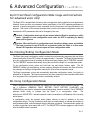
6. Advanced Configuration890-=qwertyuio
Esprit Front Panel Configuration Mode Usage and Instructions
For advanced users only!
The Esprit UPS is shipped from the factory with a configuration that is suitable for most applications.
However, there are some circumstances where modification of the UPS operating parameters is
required. A special configuration mode, accessible from the front panel, has been provided for this
purpose. This section of the manual describes how to use the front panel configuration mode and
describes the UPS parameters that can be changed by the user.
Caution: Configuration mode can only be entered when the Esprit is operating on utility
power. Attempts to enter configuration mode when the UPS is operating on battery
power will be ignored.
Caution: When the Esprit is in configuration mode, transfers to battery power are inhibited.
The load connected to the UPS will not be protected while the Esprit is in this mode.
Normal UPS operation will resume upon exit from configuration mode.
6A. Entering/Exiting Configuration Mode
The Esprit front panel configuration mode is entered by simultaneously depressing the top (Alarm
silence) and bottom (Power OFF) buttons for approximately 1-2 seconds. The Esprit will acknowledge
entry into configuration mode by sounding the buzzer and slowly flashing the AC PRESENT indicator.
The AC PRESENT indicator blinks slowly during the time that the Esprit is in configuration mode.
To exit configuration mode, press and hold both top and bottom buttons again. The AC
PRESENT indicator will stop flashing, and the remaining indicators will resume their normal function.
Any changes to the Esprit configuration made by the user will be permanently saved.
The Esprit incorporates a timer that automatically terminates configuration mode if no activity is
detected for 30 seconds. This feature prevents the unit from remaining in the vulnerable offline state
for a long period if the configuration mode is accidentally entered.
6B. Using Configuration Mode
When configuration mode is activated, the usage of the front panel status indicators changes. The
top 4 indicators (GENERAL FAULT, BATTERY FAULT, BATTERY CHARGING, and
OVERLOAD) are now used to indicate the internal feature being viewed or modified. The AC PRESENT
indicator blinks slowly to indicate that the Esprit is in configuration mode.
The
bottom-most ON BATTERY indicator shows the state (on/enabled or off/disabled) of the currently
active feature.
In configuration mode, the topmost button (Alarm silence) is used to advance to the next
configuration setting. The top 4 indicators, which light in unique patterns to indicate which option is
being viewed/modified, cycle forward each time the top button is pressed. The bottom button (power off)
is used to toggle the current option ON or OFF. The ON BATTERY indicator toggles on and off each
time the bottom button is pressed.
6—1
It is possible to cycle backward through the configuration options by pressing and holding the top
button. A given option setting can be forced to its factory default state by pressing and
holding the bottom button.
The middle (Power ON) button is not used in configuration mode.
To leave configuration mode, simultaneously depress and hold in both the top and bottom
buttons until the buzzer sounds and the AC PRESENT indicator stops flashing. Any changes made
to the Esprit configuration will now be permanently saved.
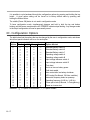
6C. Configuration Options
The table below lists the options that can be changed by the user in configuration mode, and shows
which front panel indicators will be on for each option.
Option
Number
0
1
2
3
4
5
6
7
8
9
10
11
12
13
14
15
Fault
—
Indicators
Batt Fail Charge Overload Option affected
—
—
—
Extended Battery switch A
—
—
—
Extended Battery switch B
—
—
Extended Battery switch C
—
—
Operating voltage switch A
—
—
Operating voltage switch B
—
—
Input voltage tolerance switch A
—
Input voltage tolerance switch B
—
Test alarm
—
—
Limit run time on battery power
—
—
Cold start enable
—
Auto restart after low battery shutdown
—
UPS mode (On=Normal, Off=Line condition)
—
Automatic frequency detect on powerup
—
Operating frequency (0=50 Hz, 1=60 Hz)
Comm port mode (0=Normal, 1=Tuning/factory)
Power-on inverter test
*
*
*—
*
*
*—
*
*
*
*—
*
*
*
*—
*
*
*
*—
*
*
*
*
*—
*
*
*
*
*
*
*
*
*
Indicators: ( ) = Option On/illuminated, ( — ) = Option Off/dark
*
6—2
—
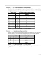
Options 0, 1, 2 – Extended Battery Configuration
These three option switches should be changed as shown in the table below when new battery
cabinet(s) are added to the UPS. The standard setting for these options are all OFF, selecting
the single/internal battery module option.
0 (A)
Option Setting
1 (B)
2 (C)
Number of battery cabinets installed
Esprit 3 & 4
(SlimLine)
—
—
—
Internal only
*
—
—
—
1
*
*
—
—
2
—
3
*
*
*
*
4
*
—
—
*
—
5
*
*
*
Indicators: ( ) = Option On/illuminated
*
6
7
( — ) = Option Off/dark
Options 3, 4 – Operating voltage selection
These two options select the nominal operating voltage of the UPS as shown in the table below.
The factory setting is 3=Off, 4=Off, which configures the Esprit for 120V (230V) operation.
Switch Setting
3 (A)
4 (B)
Nominal Operating Voltage
Low Voltage
—
—
120 V
*
—
—
100 V
*
*
127 V
*
Indicators: (
* ) = Option On/illuminated
Custom
( — ) = Option Off/dark
Do not select the "Custom" setting (Option 3 & 4 both ON) unless you are instructed to do so
by MGE service.
6—3
Options 5, 6 – Input Voltage Tolerance
Use these two option switches to select the Esprit’s sensitivity to low/high input voltage conditions.
The Esprit will switch to battery power when the utility voltage falls outside the range selected.
The percentages shown in the table below are subtracted/added to the nominal voltage setting
as set by options 4, 5. The factory setting is 5=OFF, 6=OFF which selects the –15/+10% range.
Switch Setting
5 (A)
6 (B)
Input Voltage Tolerance
Low limit
High limit
—
—
- 15%
+ 10%
*
—
—
- 20%
+ 15%
*
*
- 10%
+ 10%
*
Indicators: (
* ) = Option On/illuminated
Custom
( — ) = Option Off/dark
Do not select the "Custom" setting (Option 5 & 6 both ON) unless you are instructed to do so
by MGE service.
Option 7 – Test Alarm
The normal state of this option is OFF. Turning it on will instruct the Esprit to issue a "User Test
Fault". This condition does NOT affect the UPS operation in any way, but it does close the Low
Battery contact on the DB9 communication port, and activates the FAULT indicator and audible
alarm (pattern short-short-long). You can use this option switch to test hardware connected to
the Low Battery contact without actually running the Esprit battery down.
To clear the User Test Fault, set this option to OFF, or follow the "Alarm Clear" procedure. Press
and hold the top button.
Option 8 – Limit run time on battery power
The normal setting for this option is OFF, which allows the UPS to operate on battery for the
maximum time possible. The Esprit run time on battery is limited only by the capacity of it’s battery
system and the battery state of charge.
If Option 8 is turned on, the Esprit will run a maximum of 15 minutes on battery power before
turning itself off. Actual run time may be less, depending on size of battery system and load.
Option 9 – Cold Start (allow UPS to run on battery power on startup)
When Option 9 is turned ON (factory setting), the UPS is allowed to start up on battery power
if the AC input voltage is not present or not of satisfactory quality. The ability to run on battery
power immediately upon startup is known as "cold start" capability.
If this option is turned OFF, the UPS will start up with its output OFF if input AC is not present or usable.
The output will not be turned on until input AC is present and usable. Once the UPS turns on it’s
output, a subsequent loss/disturbance of input AC will cause the UPS to run on battery power as usual.
6—4
Option 10 – Automatic UPS restart after Low Battery shutdown
The factory setting for this option is ON, which allows the UPS to automatically turn its
output back on following a Low Battery shutdown once input AC is present. This setting is the
usual one for applications where the UPS is connected to automated or unattended
equipment that is capable of restarting itself without direct human intervention.
If the load connected to the UPS requires special attention when it is powered up, this option
should be turned OFF. When Auto Restart is turned off, the UPS output will stay turned off until
it is manually restarted by pressing and holding the top silence/restart button on the front panel.
Option 11 – Automatic UPS mode
The default setting for Option 11 is ON, which allows the Esprit to act like a typical UPS. The
UPS will automatically switch from utility to backup power as needed.
If this option is turned off, the Esprit acts like a line conditioner. The battery backup
system is disabled. If the input utility power is acceptable, the Esprit will pass it through to the
load. If the input power is unacceptably low or high, the load power is removed. The Esprit will
NOT operate on battery power if Option 11 is turned off!
Option 12 – Automatic Frequency Detect
When this option is set the factory default ON setting, the Esprit will analyze the input power
when it is turned on, and configure itself to operate at the proper frequency (50 or 60 Hz). If
utility power is not present when the Esprit is turned on, it will configure itself based on the
frequency setting in place when the unit was last turned off (see option 13 setting).
If this option is turned OFF, the Esprit will configure itself to operate using a utility power
frequency set by Option 13. Power-up input AC frequency analysis is not performed.
Option 13 – Operating Frequency selection
This option setting is only effective if Option 12, Automatic Frequency Detect is turned off. If
Option 12 is turned off, this option (13) setting can be used to select the Esprit’s nominal operating frequency. If this option is OFF, 50 Hz operation is selected. If ON, 60 Hz
operation is selected.
The factory setting for this option is ON, selecting 60 Hz operation at startup. Note,
however, that the setting of this option is overwritten by the UPS logic if option 12 (Automatic
Frequency Detect) is enabled. If the Esprit is powered up from a 50 Hz source with option 12
enabled, the setting of this option (13) will be forced to OFF.
Option 14 – Communication Mode Selection
This option should be left in it’s factory-standard OFF setting unless you are instructed to turn
it ON by MGE Service. If this option is inadvertently turned ON, the Esprit may be
rendered incapable of operating with UPS monitoring and control software, including MGE’s
Solution-Pac software.
6—5
Option 15 – Power-On Inverter Test (POIT)
When this option is set to the factory default ON setting, the Esprit will perform a short
battery/inverter test shortly after it is turned on. This test is only performed only if the UPS is
able to power up the load from utility power first. If the POIT is enabled, the UPS will power up
the load from utility power, then briefly switch to battery power approximately
5-7 seconds after it is powered up. The UPS runs on battery for only 3-5 seconds, so no
significant drain on the battery will occur.
The POIT is disabled if this option is turned OFF. The setting of this option has no effect on the
scheduling and execution of the monthly inverter/battery test, which runs less
frequently than the POIT but is considerably more exhaustive.
6—6
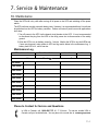
7. Service & Maintenance
7A. Maintenance
Clean the UPS with a dry cloth after turning off all power to the UPS and switching off the power
switch.
The UPS performs monthly automatic battery tests. However, it is recommended that a 6 month test
be performed on the UPS for battery condition. Perform all tests off peak hours with applications
shut down.
1. Turn off power to the UPS via the branch circuit breaker to the UPS. It is not recommended
to disconnect the plug from the UPS to the utility power due to disconnection of the safety
ground.
2. Allow the UPS to run on battery power for 1 minute. Monitor the UPS for any fault LEDs and
if none are observed, return power to UPS and log results below in the maintenance log. If
battery fault LED is lit, call for service.
Maintenance Log
UPS serial number
Date
Date of installation
Check
Location
Notes
Comments
6th month
12th month
18th month
24th month
30th month
36th month
42nd month
48th month
54th month
60th month
Places to Contact for Service and Questions
In USA or Canada, call 1-800-438-7373 M - F 24 hours. For service outside USA or
Canada, call your local distributor. You may also visit our web site at: www.mgeups.com
7—1
7B. Recycling Your UPS
In USA or Canada, call 1-714-557-1636, M - F, 6:00 A.M. to 5:00 P.M. PST. Ask for a return
goods authorization for free UPS or battery recycling. MGE does not cover return freight
charges for recycling and will not accept items without a return goods authorization number.
7—2
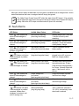
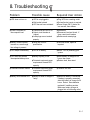
8. Troubleshooting
Problem
Possible cause
Required User Action
◗ UPS does not turn on.
◗ UPS is not plugged in.
◗ Wall socket is dead.
◗ UPS has not been activated.
◗ Plug UPS into a working outlet.
◗ Test wall socket, repair as required.
◗ Press Output ON (1) button for
one second, then release.
◗ There is no power to
the computer load.
◗ Confirm that the UPS is on.
◗ Output circuit breaker is
tripped.
◗ Load plugs are not seated
properly.
◗ See above.
◗ Disconnect load and check. If
okay, reset circuit breaker.
◗ Remove and reseat plugs.
◗ Battery Online indicator
remains on, even though
line voltage is present.
◗ Utility line is out of
specification.
◗ Test wall socket, repair as
required.
◗ UPS beeps occasionally.
◗ UPS is on battery.
◗ None - UPS is protecting your
system.
◗ UPS does not provide
the expected backup time.
◗ Battery capacity is low.
◗ Allow battery to charge for 24
hours, then retest.
◗ Reduce load, then retest.
◗ Protected equipment power
requirements exceed UPS
capacity.
◗ Overload indicator flashes.
◗ Protected equipment power
requirements exceed UPS
capacity.
◗ Reduce the load.
◗ Battery Fault indicator is lit.
◗ Battery is weak or charger is
faulty.
◗ Make sure battery is connected.
If battery is properly connected,
allow the battery to charge for 24
hours. Retest. Have batteries
replaced if condition persists.
Make sure battery charger is
plugged into a functioning outlet.
8—1
Notes
8—2
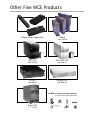
Other Fine MGE Products
Eclipse Surge Suppressors
Ellipse
300-1200 VA
ESV+ UPS
ESV+ Rack UPS
780-2200 VA
780-2200 VA
EX UPS
EX Rack UPS
700-3000 VA
700-3000 VA
Call MGE for many more power solutions:
(714) 557-1636 or (800) 523-0142
Esprit UPS
3 - 13.5 kVA
MGE GREEN SWEEP
Call MGE to return your UPS for free
recycling to a US EPA-certified recycling
center and help protect our environment.
US
MGE UPS SYSTEMS
USA (headquarters)
1660 Scenic Avenue
Costa Mesa, CA 92626
tel: (800) 523-0142
(714) 557-1636
fax: (714) 557-9788
www.mgeups.com