1
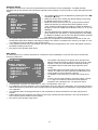
MDP 500 (G6)
DIGITAL
PREAMPLIFIER-PROCESSOR
TAPE
MONITO R
STANDBY
MODE
CINE EQ
7.1 CHANNEL
INPUT
SO URCE
SELECT
MDP 500 Digital Preamplifier - Processor
OWNER’S MANUAL
Contents
•
Introduction
Page 2
•
Installation and safety notes
Page 2
•
Accessories
Page 2
•
Setting up your system
Page 3
•
Rear panel connections
Page 3
•
Operating your system
Page 6
•
Front panel controls
Page 6
•
Remote control handset operation
Page 8
•
Setup menus
Page 10
•
Audio setup menu
Page 11
•
Speaker setup menu
Page 12
•
Source setup menu
Page 14
•
Display setup menu
Page 15
•
Trigger setup menu
Page 15
•
Using the remote in CD and DVD modes
Page 16
•
Reprogramming the remote
Page 16
•
Installing and replacing batteries
Page 16
•
Trouble-shooting guide
Page 17
•
Appendix: Details of decoding and processing modes
Page 18
•
Specifications
Page 19
1
Introduction
The Myryad MDP 500 Digital Preamplifier-Processor has been designed to offer a combination of high quality audio and
video performance with simple yet elegant styling. The MDP 500 forms the heart of a high-end home cinema and audio
system and should be used with high quality power amplifiers such as the Myryad MA 240, MA 360 and MA 500 two,
three and five channel power amplifiers.
1
The MDP 500 can decode a wide variety of discrete surround material including Dolby Digital , Dolby Digital Surround
1
2
2
2
EX , DTS , DTS-ES Matrix and Discrete , DTS Neo:6 and a proprietary mode “Surround 6.1” – together with the ability
to down-mix any source to mono or stereo. It also functions as a high quality stereo preamplifier and any stereo
analogue source can be sampled at 48kHz for further digital processing, or at 96kHz for the best sound quality without
any further processing. The 7.1 channel input is equipped with comprehensive volume control facilities and ensures that
the MDP 500 will remain compatible with new multi-channel formats as they appear – as well as providing a “pure
analogue” bypass input for audiophile analogue sources such as DVD-Audio and SACD.
The MDP 500 also has several music modes that may be used to enhance a normal two channel stereo signal. These
1
1
2
modes include Dolby Pro Logic , Dolby Pro Logic II , DTS Neo:6 , and two “music” modes: Natural, and Party.
The MDP 500 can accept up to six digital input sources, eight line-level input sources, plus a tape loop and two
additional record outputs. It has six composite and S-Video inputs, composite and S-Video monitor outputs, composite
and S-video record outputs and an S-Video monitor output without OSD (On Screen Display) for highest quality video
performance.
The MDP 500 automatically senses the type of the incoming digital audio signal and selects the best mode for that
signal. The user can also bypass the digital section of the MDP 500 and connect, for example, a high quality stereo
source to the Left and Right channels of the 7.1 channel input.
The MDP 500 is supplied with a comprehensive learning remote control handset which is pre-programmed to control
the MDP 500 and other Myryad products. In addition to the MDP 500 it can also control up to 7 other products using a
combination of the pre-programmed Myryad codes and either recalling one of its internally stored code sets, or learning
the codes of a product’s own remote.
Options for system integration are provided by My-Link input/output connectors to interface with other Myryad products,
by the three 12VDC trigger outputs to control external equipment and by communication with a PC or home automation
system via the RS 232 interface.
Installation note
This preamplifier generates a modest amount of heat and thus requires ventilation. Do not place it on a rug or other soft
surface into which it could sink. The MDP 500 should not be placed in a built-in installation such as a bookcase or rack
unless proper ventilation is provided.
CAUTION:
To prevent a fire or shock hazard, do not permit this product to become wet. If liquid is accidentally
spilled on it, immediately shut off its power at the wall socket and unplug the AC power cord. Allow sufficient time for
complete evaporation to occur before operating the preamplifier again. If the liquid is anything but water and/or alcohol,
the preamplifier should be examined by a qualified service technician before it is used again.
Do not remove the cover, or attempt to modify or repair the preamplifier yourself. Refer all servicing to a qualified
technician.
Accessories - Your MDP 500 is supplied complete with the following accessories:
• Separate mains power cord to suit country of purchase.
• Myryad Audio-Video Learning Remote Control handset.
• Four AAA batteries for handset
• Home Theater Master SL-9000 Operating Manual
1.
Manufactured under license from Dolby Laboratories.
Dolby", "Pro Logic", "Surround EX", and the double-D symbol are trademarks of Dolby Laboratories.
2.
“DTS”, “DTS-ES Extended Surround”, and “Neo:6” are trademarks of Digital Theater Systems, Inc.
2
SETTING UP YOUR SYSTEM
5
6
7
8
14
SAT
10
DIGITAL
OUTPUT
REC
AUX 2
9
15
DIGITAL INPUTS
COAX 1
RS232
CONTROL
INPUT
COAX 3
IN
MON
COMPOSITE
VIDEO OUTPUTS
17
OUT
MY-LINK
TV
AUX 1
VCR
DVD
COMPOSITE VIDEO INPUTS
16
AUX 2
AUX 1
SAT
VCR
S-VIDEO INPUTS
TV
DVD
MON-HQ MON-OSD
REC
S-VIDEO OUTPUTS
COAX 2
LF
LS
COAX 4
CTR
OPT 1
OPT 2
LB
LF
RB
RF
LS
CTR
LB
POWER
OFF
1
2
3
REMOTE TRIGGER
OUTPUTS
MDP 500
DIGITAL
PREAMPLIFIER
PROCESSOR
L
SERIAL
NUMBER
R
AUX 2
AUX 1
SAT
VCR
TV
ANALOGUE INPUTS
DVD
CD
TUNER
3
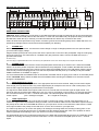
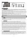
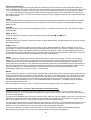
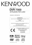
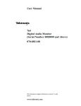
REAR PANEL CONNECTIONS
L
R
ON
PLAY
REC
TAPE
4
1
2
RECORD OUT
RF
13
11
RS
SUB
7.1 CHANNEL INPUTS
12
RS
SUB
7.1 CHANNEL OUTPUTS
RB
2
1
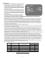
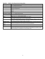
CAUTION: Before making any connections to your MDP 500 make sure that it is switched OFF at the rear and that its
power cord is disconnected (either at the wall socket, or at the rear of the MDP 500). All equipment being connected to
the MDP 500, either directly or indirectly, must also be switched OFF before any connections are made.
Failure to follow these precautions may result in excessive ground currents flowing briefly into the MDP 500 which can
permanently damage internal connections and will invalidate your Warranty.
1.
POWER inlet
Before making any connection, check that the mains voltage or range of voltages printed on the rear panel includes
your local mains supply voltage.
Plug the female (socket) end of the power cord into the power inlet on the rear of the preamplifier. Plug the male (plug)
end of the cord into a "live" wall socket or a suitable heavy duty extension cable. Connect the MDP 500 only to a
grounded wall socket.
UK version only:
The mains plug is supplied fitted with a fuse. It should only be replaced with a fuse of the same rating which complies with BS1362.
2.
POWER switch
Press the bottom of this rocker switch to switch the preamplifier ON and the top to switch it OFF. When the POWER
switch is in the OFF position all power is disconnected from the preamplifier. In this condition the MDP 500 cannot be
powered up from the front panel or the remote control. When the POWER switch is in the ON position (and the power
cord correctly inserted and plugged into a live wall socket) the MDP 500 will power up in standby mode (see FRONT
PANEL CONTROLS, STANDBY on page 6).
It is recommended that the POWER switch is turned OFF if the MDP 500 is not going to be used for an extended period
of time. CAUTION: always switch the MDP 500 to STANDBY before switching the POWER off to avoid loud noises
through the loudspeakers.
3.
ANALOGUE stereo inputs
Connect the analogue audio output cables of the appropriate devices to these sockets. Always connect these inputs,
even though you may intend to listen only via the digital inputs (for example in the case of a CD or DVD player). This
ensures that a signal will always be present at the record outputs.
The signal from ANALOGUE stereo inputs is fed to an A-D converter that converts the signal to digital format. The
signal can then be processed using Dolby Pro Logic, Pro Logic II, DTS Neo:6 or other modes. The signal is then fed to
D-A converters and thence to the 7.1 channel line outputs. The selected signal is also fed to the three ANALOGUE
record outputs.
[A-D = Analogue to Digital;
D-A = Digital to Analogue]
4.
TAPE input/output
These connectors are suited to any type of tape recorder, including high-quality "3-head" types which allow you to
monitor the signal off the tape whilst it is being recorded. Connect a stereo cable from the TAPE REC output sockets of
the preamp to the LINE IN or RECORD IN sockets on your tape deck. Connect a second stereo cable from the TAPE
PLAY input sockets of the preamp to the LINE OUT or PLAY OUT sockets on your tape deck.
The TAPE loop allows you to monitor the quality of an Analogue recording whilst the recording is taking place. It can
also be used for connecting devices such as equalizers into the analogue signal path. Note: if an equalizer is used it
must be bypassed when listening to Pro Logic sources to ensure correct decoding.
Any ANALOGUE stereo source selected for listening on the MDP 500 will automatically be fed to the TAPE REC output
sockets for recording. Recordings cannot be made from a source connected to the digital inputs or the 7.1-channel
inputs.
3
5.
COMPOSITE VIDEO inputs
Connect the composite video output cables from your video sources to these inputs. Be careful to use inputs with the
same name for the composite video, S-Video and analogue audio cables from a single source (e.g. cables from a VCR
should go to the VCR S-VIDEO, VCR COMPOSITE VIDEO and VCR ANALOGUE inputs).
The composite video signal is selected from these sources, and the signal is fed out from the COMPOSITE VIDEO
record (REC) and monitor (MON) outputs. On Screen Display information is added to the monitor (MON) output.
6.
COMPOSITE VIDEO RECORD and MONITOR outputs
Connect the composite video input of your VCR to the COMPOSITE VIDEO REC output. Connect the composite video
input of your display device (TV) to the COMPOSITE VIDEO MON output. The On Screen Display (OSD) information is
present on this output. You can also use the COMPOSITE VIDEO MON output even if no composite video source is
connected. The selected S-Video signal is down-mixed to this output and can be used for monitoring. The OSD can be
switched off on the MON output using the Display setup menu.
7.
S-VIDEO inputs
Connect the S-Video output cables from your video sources to these inputs. Be careful to use inputs with the same
name for the composite video, S-Video and analogue audio cables from a single source.
S-Video signals are of higher quality than composite video signals. Therefore if your source devices have S-Video
outputs it is recommended that you use them, together with the S-Video inputs on your display. S-Video inputs are also
automatically down-mixed to feed the composite video MON OSD output for displays which do not have S-Video inputs.
8.
S-VIDEO RECORD, MONITOR and High Quality MONITOR outputs
Connect the S-Video input of your VCR to the S-VIDEO REC output. Connect the S-Video input of your display device
(TV) to the S-VIDEO MON output. The On Screen Display information is displayed in this output, but may be switched
off using the Display setup menu. The MON HQ output displays the selected source without routing it through the On
Screen Display circuit thus giving the best possible video quality. If a composite video source is selected, the S-Video
outputs will carry only a black-and-white video signal.
9.
COAXIAL DIGITAL audio inputs
Connect the coaxial digital output cables of your source devices to these inputs. The digital inputs can be freely
associated to any analogue audio or audio-video sources (see Source setup menu for further reference), but the MDP
500 is supplied set up as follows:
Digital audio input
Associated to input
COAX 1
AUX 1
COAX 2
AUX 2
COAX 3
SAT
COAX 4
TUNER
OPTICAL 1
CD
OPTICAL 2
DVD
Re-assigned to input
If you re-assign any of the digital inputs to different analogue inputs, record this in the blank column provided. You may
assign a digital input to more than one analogue input if desired.
Note: The “SPDIF” digital interface is very sensitive to the quality of connection when using 96kHz sample rate
sources. Always use a high quality digital coax interconnect if 24bit/96kHz operation is desired.
10.
OPTICAL DIGITAL audio inputs
Connect the Optical Digital audio cables to these inputs. These inputs can also be freely associated to any analogue
audio or audio-video sources, but the MDP 500 is supplied set up as shown in the table above.
Note: The “SPDIF” digital interface is very sensitive to the quality of connection when using 96kHz sample rate
sources. Always use a high quality optical interconnect if 24bit/96kHz operation is desired.
4
11.
7.1 CHANNEL INPUTS (Left Front, Centre, Right Front, Left Surround, Right Surround, Left Back, Right
Back and Subwoofer)
Connect the audio line outputs from any multi-channel analogue source such as a DVD-Audio player or Super Audio CD
(SACD) player to these inputs using up to eight interconnect cables (or four stereo cables) as necessary. The Left Back
and Right Back channels are provided for future surround formats. The 7.1 CHANNEL inputs may be used with any
mono, stereo, 5.1 channel or 7.1 channel source.
You may use these inputs as an “Analogue Direct” input if you want to bypass the digital section of the MDP 500 (use
Left Front and Right Front for a stereo source). The record outputs are not active when the 7.1 channel input is
selected.
12.
7.1 CHANNEL OUTPUTS (Left Front, Centre, Right Front, Left Surround, Right Surround, Left Back,
Right Back and Subwoofer)
Connect these outputs to the line inputs of your power amplifier(s), such as the Myryad MA 240, MA 360 or MA 500 two,
three and five channel power amplifiers. The SUB output will normally be fed to the low-level Line Input of an active
subwoofer. Alternatively it may feed a separate power amplifier and passive subwoofer.
If the setup has only one rear speaker, its amplifier should be connected to the Left Back output.
13.
RECORD 1 & 2 outputs
The REC outputs carry the signal from whichever ANALOGUE stereo source device is currently selected (except the
source connected to the TAPE PLAY input or the 7.1 CHANNEL input). These outputs may be connected to the inputs
of any recording device, or the signal may be used in a multi-room set-up to feed power amplifiers in other rooms.
14.
DIGITAL output
Connect the optical input of your digital recording device to the DIGITAL output. The selected digital source is fed to this
output in optical digital format.
15.
MY-LINK input/output
When the MDP 500 is used in a system with other Myryad M-Series products, all may be joined together via the MyLink. The MY-LINK output of the MDP 500 should be connected to the MY-LINK input of the next product and its MYLINK output connected to the MY-LINK input of the next and so on in “daisy-chain” fashion. This inter-linking provides
three main benefits.
Firstly, when the MDP 500 is switched out of (or into) STANDBY, either using the front panel switch or the remote
control, all the other linked Myryad products will switch out of (or into) STANDBY at the same time. Note: there is a short
processing delay (about 1.5 seconds) between the MDP 500 switching into STANDBY and the My-Link control pulse
switching the other linked units into STANDBY.
Secondly, only one linked product with its own Infra Red receiver (e.g. a Myryad CD player, but not a Power Amplifier)
needs to be “in line of sight” of the remote handset. The My-Link will carry the remote command from any IR receiver to
all the other products that are linked together.
Finally, the MY-LINK may be used to interface with various proprietary multi-room control systems. Contact your Myryad
dealer or Myryad Systems Ltd. for details or visit the Myryad website at www.myryad.co.uk.
16.
RS 232 CONTROL interface
You can connect the MDP 500 to a home automation system through this interface. Contact your Myryad dealer or
Myryad Systems Ltd. for details or visit the Myryad website at www.myryad.co.uk.
17.
REMOTE TRIGGER OUTPUTS – 1. 2 and 3
You can connect the DC trigger inputs of any audio or other equipment to these TRIGGER outputs. The TRIGGER
outputs may be activated when the MDP 500 is switched out of STANDBY and turned off again immediately when the
MDP 500 is switched into STANDBY again. The TRIGGER outputs may be programmed to be activated under other
conditions (see Trigger setup menu section, page 15).
The TRIGGER outputs deliver +12V DC with a maximum current of about 40mA from each of the three trigger outputs.
CAUTION: THE TRIGGERS SHOULD ONLY BE CONNECTED OR DISCONNECTED WHEN THE POWER SWITCH
IS OFF, OR THE UNIT IS DISCONNECTED FROM MAINS POWER.
5
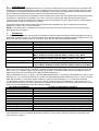
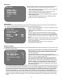
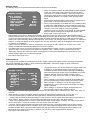
OPERATING YOUR SYSTEM
TAPE
MONITO R
STANDBY
MODE
CINE EQ
7.1 CHANNEL
INPUT
SO URCE
SELECT
MDP 500 Digital Preamplifier - Processor
1
2
3
4
5
6
7
8
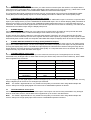
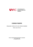
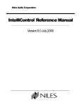
FRONT PANEL CONTROLS
1.
STANDBY switch
When the preamplifier is plugged into a live wall socket and the POWER switch is turned ON, the display will read
“Myryad MDP500 Powering-up” after about 3 seconds. This display will remain for around 5 seconds before the display
goes blank and the LED (Light Emitting Diode) in the STANDBY button will glow red. The MDP 500 is now in standby
mode, with its internal circuitry powered up but inactive.
When the STANDBY button is pressed the preamplifier circuitry will be activated and the last used INPUT and last used
MODE automatically selected. The LED in the STANDBY button will change to blue, the display will briefly read “Myryad
MDP500 Initialising” and the LINE outputs will be muted for a few seconds. During this delay period the blue LED in the
STANDBY button will flash to indicate this mute condition.
When the STANDBY button is pressed again the preamplifier will be returned to standby mode, the display will briefly
read “Myryad MDP500 Shutting down” and the LED in the STANDBY button will glow red again.
CAUTION: always switch the MDP 500 to STANDBY before switching the POWER off at the rear to avoid loud noises
through the loudspeakers.
CAUTION:
be followed.
When in standby mode the internal circuitry of the MDP 500 is still live, so all safety precautions MUST
2.
Display
Located behind this window is a high quality blue Vacuum Fluorescent Display (VFD) which indicates the operating
condition of the MDP 500 – including the selected input, operating mode and volume setting. Also behind this window
(and located between the “M” and “Y” of the word MYRYAD) is the Infra-Red detector which receives the commands
sent to the MDP 500 from the remote handset.
3.
VOLUME control
The volume control adjusts the sound level of the signal fed to the 7.1 CHANNEL line outputs. It does not affect the
signals fed to the TAPE REC sockets so it can safely be adjusted whilst making a recording.
The volume setting is indicated in the bottom right of the VF display, for example “vol: -35”. The display indicates the
preamplifier gain in dB (decibels) referenced to THX standard gain (-2.5dB). When first switched on the volume is set
automatically to –20, which is a typical listening level. If the volume is set below –20 this will be remembered when the
MDP 500 is switched into STANDBY and re-instated when it is switched on again. If the unit is switched to STANDBY
with a volume setting higher than –20, it will be reset to –20 when switched on again to protect against excessive sound
levels.
When the control is rotated slowly the volume is increased (or decreased) in 1dB steps for each detent of the control. If
the control is rotated quickly the volume changes in larger steps so that the volume can easily be adjusted over a wide
range. When first using this control take great care when increasing the volume as the sound can get very loud very
quickly. The volume control range is from -90dB to +15dB when all channel level adjustments (e.g. in the Speaker level
or Audio setup menus) are set to zero or negative values. If any of the trims is set to a positive figure, the maximum
volume setting is reduced by the same amount to prevent inadvertent digital overload.
When the volume level is being changed (using the front panel control or the remote), there may be small “ticking”
sounds at each volume step. These will be more noticeable at higher volume settings. These noises are quite normal
and have no effect upon the sound quality once the volume control has been set.
4.
SOURCE SELECT ! and "
These buttons scroll up or down through the inputs to select the source (audio or audio-video) that is fed to the main
outputs for listening and viewing. The same signal will also be fed to the TAPE REC and REC 1 & 2 output sockets for
recording. The display shows which input has been selected. The SOURCE buttons scroll through all the inputs except
TAPE. TAPE and 7.1 CH inputs are selected by the TAPE MONITOR and 7.1 CHANNEL buttons – see below.
When an input is selected, the MDP 500 will automatically switch to the operating MODE last used with that input, or to
the correct digital decoding if an active digital source is assigned to the input.
6
5.
TAPE MONITOR
When you press the TAPE MONITOR button you can hear the output signal from a recording device connected to the
TAPE PLAY sockets on the rear panel. This is a "toggle" function switch: you press it once to engage and press again
to disengage. The TAPE MONITOR input also disengages if a new source is selected either from the remote or front
panel. Pressing the TAPE button has no effect on the other source select buttons.
The signal source selected by the SOURCE ! and " buttons will be fed to the TAPE REC output sockets, irrespective
of whether the TAPE button is engaged or not. Thus, if you have a "three-head" tape deck that permits off-tape
monitoring you can use the TAPE button to switch back and forth between the source signal and the off-tape signal, to
check its quality, whilst the recording is in progress.
Pressing the TAPE button does not affect the operating mode of the MDP 500, which continues to be the mode
applying to the input source currently selected.
NOTE: If the TAPE button is engaged with no signal source connected to the TAPE PLAY, or with no tape running,
then you will hear only silence.
6.
MODE button
The MODE button is used to cycle through the available processing modes for analogue stereo and digital sources (no
processing is possible for the 7.1 channel analogue input). Not all modes are possible for all types of signal source. The
table below lists the possible options, in the order in which they are selected by the MODE button.
SIGNAL TYPE
Dolby Digital 3/2.1
Dolby Digital Surround EX
DTS 3/2.1
DTS-ES Matrix
DTS-ES Discrete
Dolby Digital 2/0
PCM (up to 48kHz sampling)
PCM (96kHz sampling)
Analogue stereo
ALLOWED MODES
Direct, Dolby Digital EX, Surround 6.1, Mono, Stereo
Direct, Dolby Digital EX, Surround 6.1, Mono, Stereo
Direct, DTS Neo:6, Surround 6.1, Mono, Stereo
Direct, DTS-ES Matrix, Mono, Stereo
Direct, Mono, Stereo
Direct, Dolby Pro Logic, Dolby Pro Logic II Movie, Dolby Pro Logic II
Music, DTS Neo:6 Cinema, DTS Neo:6 Music, Natural, Party, Mono
Stereo, Dolby Pro Logic, Dolby Pro Logic II Movie, Dolby Pro Logic II
Music, DTS Neo:6 Cinema, DTS Neo:6 Music, Natural, Party, Mono
Stereo, Mono
Stereo, Stereo96, Dolby Pro Logic, Dolby Pro Logic II Movie, Dolby Pro
Logic II Music, DTS Neo:6 Cinema, DTS Neo:6 Music, Natural, Party, Mono
When the “Direct” MODE is chosen, the signal source is decoded in the expected way – for example DTS 3/2.1 material
will be processed using DTS 3/2.1 decoding. The MDP 500 will automatically choose “Direct” for a new source except
that, in a 6.1 or 7.1 speaker system, the processing for DTS 3/2.1 and DTS-ES Matrix signals will default to Neo:6 or
Matrix respectively (this is a requirement of Digital Theater Systems Inc.).
With DTS-ES Matrix sources, in “Direct” mode the MDP 500 will output 5.1 channels (no back speakers). “Matrix” mode
will output 6.1 or 7.1 channels as desired. In a similar way, with Dolby Digital Surround EX sources, in “Direct” mode the
MDP 500 will output 5.1 channels (no back speakers). “DD EX” mode will output 6.1 or 7.1 channels as desired.
The loudspeaker channels which are active in the various modes are listed in the table below. The subwoofer is not
included in this table since it is active if selected in the speaker setup and if any of the active speakers are set to “small”
(and of course any loudspeaker set to “No” will not be active).
DECODING/PROCESSING
Dolby Digital 3/2.1
DTS 3/2.1
Dolby Digital EX
DTS-ES Matrix or Discrete
DTS Neo:6 / Cinema / Music
Surround 6.1
Mono
Stereo / Stereo96
Dolby Pro Logic
Dolby Pro Logic II Movie/Music
Natural / Party
ACTIVE LOUDSPEAKER CHANNELS
L / R / C / LS / RS
L / R / C / LS / RS
L / R / C / LS / RS / LB / RB
L / R / C / LS / RS / LB / RB
L / R / C / LS / RS / LB / RB
L / R / C / LS / RS / LB / RB
C
L/R
L / R / C / LS / RS
L / R / C / LS / RS
L / R / C / LS / RS
More details of the various decoding and processing modes are given in the Appendix on page 18. Details of how to
make adjustments to the processing parameters in Dolby Pro Logic II Music mode can be found in the Audio setup
menu section on page 11.
7
Notes regarding operation in “Stereo 96” mode and with 96kHz/24bit digital sources (including DTS96/24).
•
•
•
•
There is no digital processing of 96kHz sample rate signals so there is no subwoofer output possible in Stereo96
mode or with 96kHz/24bit digital PCM sources.
The MDP500 can accept ”DTS96/24” sources. The data is processed at 48kHz and all channel outputs (including
subwoofer) are available. The front panel display will indicate the same as with normal (48kHz) DTS sources.
When using a 96kHz sample rate digital PCM source, always use a high quality interconnect, coaxial or optical as
desired. 96kHz operation is very sensitive to the quality of interconnection.
When using a 96kHz sample rate digital source the display (both front panel and OSD) still reads “Digital PCM”. To
confirm that the source is 96kHz, press the MODE button repeatedly. With a 96kHz digital source, only Mono and
Stereo modes will be accessible, no other processing.
7.
CINE EQ button
When the CINE EQ button is pressed Cinema Equalisation will be switched on and the text CEQ will appear in the front
panel display and the On Screen Display status screen. Press again to switch CINE EQ off.
The sound tracks on movies can sometimes sound rather bright because they have been balanced to take into account
the acoustics of typical cinemas (movie theatres). Myryad’s Cinema Equalisation has been carefully designed to
compensate for this brightness without impairing treble sound quality.
8.
7.1 CHANNEL INPUT button
The 7.1 CHANNEL INPUT in the MDP 500 provides compatibility with future multi-channel formats. Pressing this button
provides instant access to select the 7.1 CHANNEL INPUT. It may be deselected by changing the source using the
SOURCE SELECT buttons, or by pressing the 7.1 CHANNEL INPUT button again. In the latter case the MDP 500 will
return to the input previously selected before the 7.1 CHANNEL button was pressed.
REMOTE CONTROL HANDSET OPERATION
The MDP 500 is supplied with the Myryad Audio-Video Learning Remote Control handset. It will control not only your
MDP 500, but also Myryad CD players, DVD players and FM tuners.
The Myryad Audio-Video Learning Remote Control handset is a very powerful and flexible remote. Apart from
controlling the Myryad products mentioned above, it can also control up to 5 further products (e.g. VCR, TV, Set-Top
box etc.) – either by calling up pre-programmed code sets which are already stored in the handset, or by “teaching” the
Myryad handset from your existing remote.
The Myryad Audio-Video Learning Remote Control handset is custom-made for Myryad by Universal Remote Control
Inc.. Fully detailed instructions for the programming and operation of the remote are in the “Home Theater Master SL9000 Operating Manual” supplied with the MDP 500.
To control Myryad products the handset must be set to AUDIO, CD or DVD mode by pressing the AUD, CD or DVD key
at the top of the handset. AUDIO mode is used for operating the MDP 500 (or Myryad integrated amplifiers or
preamplifiers) and Myryad FM tuners. CD mode is used for operating Myryad CD players and DVD mode for Myryad
DVD players. (Note, some Myryad DVD players use different remote codes, so you may need to re-program the DVD
page of the handset. See your Myryad DVD player Owner’s Manual for details.)
Remote operation of the MDP 500 and Myryad amplifiers and FM tuners (AUDIO mode).
The remote control keys are listed in order, from left to right and from the top of the handset down. The top eight keys
(AUD, CD, DVD, AUX, SAT, TV, VCR, CBL) set the operating mode of the handset. To control the MDP 500 first press
the AUD key to switch to AUDIO mode. In this mode the remote will also control Myryad FM tuners and operates exactly
as described in your Myryad tuner Owner’s Manual.
POWER
This key operates in exactly the same way as the STANDBY button on the front panel. It sends the command to switch
the MDP 500, or any other Myryad preamplifier or integrated amplifier, into or out of standby mode.
VOL ! and "
Pressing one of the VOLUME ! or "keys will increase or decrease volume setting - in exactly the same way as
rotating the front panel volume control. If the preamplifier is in mute mode (after pressing MUTE on the R/C handset)
then pressing the VOLUME ! key will automatically disengage mute mode and re-connect the signal to the power
amplifier and loudspeakers. This prevents an excessively high volume level from being set by mistake.
CH ! and "
Tuner functions
These keys operate in a similar way to the rotary tuning knob on the MT 100 and exactly as the front panel TUNE
UP/DOWN keys on other Myryad tuners. A single brief key press will move either up or down in frequency or preset
number or initiate SEARCH mode. In MANUAL and PRESET modes, when a key is pressed and held down the tuner
will scan automatically in the desired direction.
8
MUTE
Pressing the MUTE key on the handset will engage mute mode and the MDP 500’s 7.1 CHANNEL line outputs will be
muted. MUTE is a "toggle" function, so pressing the key again will disengage the mute mode. The mute is also
disengaged when the volume setting is increased using the VOL ! on the remote control.
T/V
Tuner function
This key sends the tuner STANDBY command and will switch the Myryad MT 100 (and any other Myryad tuner) into or
out of standby mode.
MENU
When this key is pressed the unit goes to setup mode. The up / down / left / right keys are used to navigate the menus
(see setup menu section). The unit leaves setup mode either by selecting “EXIT” from the OSD (or VFD) or by pressing
MENU key again.
GUIDE
Pressing this key once displays the status of the unit on the OSD. The status display shows selected source, audio and
video signal type, audio output type and volume information. The status display disappears after a few seconds or if you
press the same key again
EXIT
This key exits the setup mode without saving the new settings. This is used if a setup menu is adjusted by mistake.
PRE. CH
This key has no function when the remote is in “AUDIO” mode.
SEL
This key is used to select menu items in setup mode. Pressing once selects the desired menu or sub-menu.
!,",#,$ (up, down, left and right).
These keys are used to navigate in the menus. Up and down keys are used to select the parameter to be adjusted. The
left / right keys are used to adjust the selected parameter. The selected parameter is marked in the OSD by a pointer
(4) and also is shown in the bottom row of the front panel display.
SAT, AUX 1, AUX 2, DVD, TV, VCR, TUNER and CD (also marked 1, 2, 3, 4, 5, 6, 8 and 9)
All sources can be accessed from these keys directly. For example pressing DVD selects DVD video and audio signals
(and any digital source assigned to the DVD input). These are then processed and fed to the appropriate outputs for
viewing and listening.
7.1 CH (also marked 7)
The 7.1CH key operates in exactly the same way as the 7.1 CHANNEL button on the front panel. It provides instant
access to select the 7.1 CHANNEL INPUT, which is deselected when the source is changed using either the remote or
the front panel SOURCE SELECT buttons or by pressing the 7.1 CH key again.
PRESET, MANUAL and SEARCH
Tuner functions (also marked FAV, INFO and NEXT)
FM tuner Tune Mode keys. These operate exactly as the FM tuner’s front panel buttons.
DIM (also marked +10)
This key dims the front panel VF display, which may be preferred in a darkened room. This is a "toggle" function key:
press it once to dim the display and press again to switch back to full brightness.
Note: the DIM function is not available on the remote handsets supplied with earlier MDP500’s which have subsequently
been upgraded with the “G6” DSP module.
TAPE (also marked 0)
When you press the TAPE key you can hear the output signal from a recording device connected to the TAPE PLAY
sockets on the rear panel. This is a "toggle" function key: press it once to engage and press again to disengage. The
TAPE input also disengages if a new source is selected either from the remote or front panel. Pressing the TAPE key
has no effect on the other source select keys.
E-BASS (also marked ENTER)
This key switches on and off E-Bass mode. In E-Bass mode, bass signals are sent to both the main left front and right
front loudspeakers (when they have been set up as “large”; see Speaker setup - size menu on page 13) and to the
subwoofer channel, thus allowing greater bass output when full range main loudspeakers are employed.
9
TEST (also marked ALT)
This key switches on the Noise Test signal, after the LEVEL key has been pressed or from the Speaker level setup
menu. A broadband noise signal is sent first to the Left Front channel for a few seconds, then to the Centre channel and
so on through the other channels. The level of any channel may be adjusted during this cycle using either the TRIM
+/− keys or the Speaker level setup menu. While the level is being trimmed the noise signal will remain directed to
that channel, and only move on to the next after the trimming has been completed. Pressing TEST again will switch off
the noise test signal
COMP
This key activates Dolby Late Night function that compresses a Dolby Digital soundtrack so that all details are audible
even at low listening levels, but loud sounds are reduced in volume. Note: this function is only available with Dolby
Digital sources.
CINE EQ
This key switches on and off the Cinema Equalisation function. It operates in exactly the same way as the front panel
CINE EQ button.
SRCE + and −
These keys function in exactly the same way as the front panel SOURCE ! and "buttons.
MODE + and −
These keys function in exactly the same way as the front panel MODE button, but allow selection up and down through
the available modes.
TRIM + and −
These keys are for trimming speaker levels in LEVEL mode or speaker distances in DELAY (distance) mode. First
press LEVEL (or DELAY) and then adjust the relevant parameter using these keys. If LEVEL (or DELAY) has not been
pressed the keys function as temporary Subwoofer level trims (not stored in memory) and this temporary trim level is
shown briefly in the bottom right hand corner of the OSD. In the Speaker level setup menu the TRIM keys can be used
to adjust the level of the currently active speaker during TEST noise calibration.
LEVEL
This key switches on LEVEL Trim mode and will cycle though the channels for trimming – shown in the front panel
display only, not the OSD. The key is pressed once to enter level setup mode and select the Left Front channel. The
TRIM + and − keys are then used to adjust the Left Front speaker level, either using programme material, or the
TEST noise source (see above). If the TEST key is pressed the system will cycle automatically through the channels. If
the Level is being trimmed using programme material then the LEVEL key should be pressed again to advance to the
Centre channel and so on until all the channels have been trimmed, when the system will exit LEVEL mode
automatically. LEVEL trim is not active on the 7.1 Channel input.
DELAY
This key switches on DELAY (= distance) setup mode and will cycle though all active channels (including subwoofer) for
setting up the distance from the listener to each speaker – shown in the front panel display only, not the OSD. The key
is pressed once to enter delay setup mode and select the Left channel. The TRIM + and − keys are then used to set
the distance to the Left speaker. Press the DELAY key again to advance to the Centre speaker to set its distance,
followed by the Right speaker and so on. The last selected speaker is “Subwoofer” - one further press of the DELAY
key will exit DELAY setup mode.
Note: the delays are not active on the 7.1 Channel input as these signals remain in the analogue domain.
Using the setup menus – via the On Screen Display or front panel display
The setup menus are accessed by pressing the MENU key on the remote controller. The UP, DOWN, LEFT and
RIGHT arrow keys (!,",#,$) are used to navigate in the menus. The menus are shown below as they appear on the
On Screen Display (OSD).
The UP (!) and DOWN (") keys are used to move the cursor within the menu to highlight a sub-menu or function to be
adjusted. To select a sub-menu press the SEL key in the middle of the cursor keys. The functions are adjusted using
LEFT (#) and RIGHT ($) keys. The EXIT key escapes from the menu without saving.
The front panel display will show only the title line and one other line of the menu, commencing with the top line. The UP
(!) and DOWN (") keys may be used to select the other lines of the menu to access a sub-menu or function to be
adjusted. In this way all setting-up can be done using the front panel display if desired.
In each case, selecting “Exit” within a menu will return you to the previous level menu. Pressing MENU again (or
selecting Exit from the Main menu) will return to normal operation and save any new settings.
10
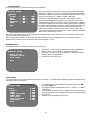
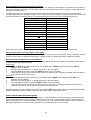
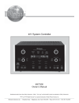
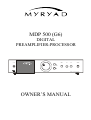
MAIN MENU
Main menu
The main menu lists the sub-menus that can be selected using the
UP and DOWN keys and accessed by pressing the SEL key.
$ Audio setup
•
Speaker setup
Source setup
Display setup
Trigger setup
•
•
•
Exit
•
•
Audio setup: bass and treble tone controls, LFE level, Dolby Pro
Logic II setup and preset setups
Speaker setup defines speaker levels, distances and sizes
Source setup defines source-related parameters
Display setup sets video formats and defines how the OSD (On
Screen Display) works
Trigger setup sets the parameters for the TRIGGER outputs
Exit returns to normal operation mode.
AUDIO SETUP
The Audio setup menu allows adjustment of the main bass and treble controls, the LFE channel level and Dolby Pro
Logic II Music mode parameters. It also allows access to the preset setup menus.
•
Audio setup
•
Dolby/DTS setup
Preset setup
$ Bass
----!
----!---Treble
----!
----!---LFE level
Exit
•
0dB
0dB
0dB
•
•
•
Bass can be adjusted between a 12 dB cut (-12 dB) and a 12 dB
boost (+12 dB), in 1dB steps.
Treble can be adjusted between a 12 dB cut and a 12 dB boost, in
1dB steps.
The LFE (Low Frequency Effects) channel contains only low
frequency signals. It is the “0.1” of the 5.1 or 6.1 channel digital
surround signal and is only present with Dolby Digital, DTS and
DTS-ES sources. LFE level can be set from -10dB to 0dB in 1dB
steps.
Dolby/DTS setup enters the Dolby/DTS setup menu for setting the
parameters in Dolby Pro Logic II Music mode and DTS Neo:6
Music mode (see below).
Preset setup enters the preset sub-menus (see below).
Exit returns to the main menu.
DOLBY/DTS SETUP
The Dolby/DTS setup menu allows adjustment of the individual parameters when using Dolby Pro Logic II Music mode
and DTS Neo:6 Music mode.
• Dolby Pro Logic II panorama, centre width and dimension settings
allow adjustment of Dolby Pro Logic II parameters. These are
Dolby/DTS setup
effective in Dolby Pro Logic II Music mode only. ”Movie” mode
$ PLII Panorama
uses fixed parameters.
Off
PLII Centre Width
3
• “PLII Panorama” wraps the sound of the front left and right
PLII Dimension
0
speakers around you for a more exciting perspective. It can be set
either On or Off. The default setting is Off.
Neo:6 Centre Image
2
• “PLII Centre Width” allows adjustment of the centre width from
“Min”, through 1 to 6 up to “Max”. Centre width allows you to
Exit
spread the centre channel sound field gradually into the left and
right front speakers. At its widest setting, all the sound from the
centre is mixed with the left and right. This control may help
achieve a more spacious sound or a better blend of front image.
The default setting is 3.
• “PLII Dimension” adjusts the front-to-back balance of the sound field to suit your test. Dimension may be set from -3
to +3, positive settings moving the sound field to the front and negative settings to the rear. The default setting is 0.
• “Neo:6 Centre Image” adjusts the centre channel image dominance by subtracting some of the centre signal from
the left and right channels. It is effective only in DTS Neo:6 Music mode (DTS Neo: 6 and Neo:6 Cinema mode
have fixed parameters). The centre image setting can be varied from 0, which allows the Left and Right Front
channels to pass unaltered, up to 5, which makes the centre channel more dominant by subtracting the maximum
amount of the centre signal from the left and right channels and can be desirable if listeners are located well offcentre. The default centre image setting is 2. The centre channel output level is not affected by the centre image
setting.
11
PRESET SETUP
When “Preset setup” is selected a third level menu appears:
Preset setup
$ Preset
Treble
Bass
Centre
Surround
Surround
Subw
----!
----!-------!
----!-------!
----!-------!
----!-------!
----!----
1
0dB
0dB
0dB
0dB
0dB
Exit
This menu allows up to five preset setups to be programmed into the
MDP 500, numbered 1 to 5. Each setup allows individual adjustment
of Treble and Bass, and Centre, Surround and Subwoofer trim levels each over the range from -12dB to +12dB in 1dB steps.
It should be noted that the three level trim adjustments (Centre ,
Surround and Subwoofer) are added to any “Speaker Level setup”
settings already made. It is therefore recommended that the “Speaker
Level setup” adjustments are made to balance the system accurately to compensate for speaker sensitivities, speaker placement and room
acoustics - while the Preset level trims are used to add personal
preferences for different sources (see “Source setup” below). The
preset tone settings are not added to the “normal” settings, but replace
them when a preset setup is in use.
Each of the five preset setups can be assigned to any desired input source (apart from 7.1 Channel and TAPE) using
the Source Setup menu (see below).
Note: Any preset level setup in use (Centre, Surround and Subwoofer) is disabled when the Level setup menu is
entered and so will also not be active when the noise test signal is in use.
SPEAKER SETUP
The Speaker setup menu allows access to three sub-menus:
•
•
•
Speaker setup
$ Level setup
•
Distance setup
Size setup
Level setup – set the relative volume level of each loudspeaker.
Distance setup – set the distance to each loudspeaker.
Size setup – to set the size of, or absence of, each loudspeaker
and bass crossover parameters.
Exit returns to the main menu
Exit
LEVEL SETUP
The Level setup menu is used to balance the system accurately - to compensate for different speaker sensitivities, their
placement and room acoustics.
•
Level setup
$ Left
Centre
Right
Right surround
Right back
Left back
Left surround
Subwoofer
Exit
•
0.0dB
0.0dB
0.0dB
0.0dB
0.0dB
0.0dB
0.0dB
0.0dB
•
•
The speaker levels can be adjusted by pressing the LEFT (#
#)
and RIGHT ($
$) keys.
The range of each level adjustment is from –15 dB to + 15 dB, in
0.5dB steps.
If any speaker has been set in the Speaker size menu (below) as
being absent, then “None” will appear in place of the level setting
in this menu.
Exit returns to the Speaker setup menu
12
DISTANCE SETUP
The Distance setup menu is used to set the distance from the listener to each loudspeaker. The MDP 500 then
calculates the amount that the sound should be delayed to each speaker in order to produce a clear and stable acoustic
image.
•
•
•
•
The speaker distances can be adjusted by pressing the LEFT (#
#)
and RIGHT ($
$) keys.
$ Left
0.0m
• Distances can be set in metres (the default setting) or feet using
Centre
0.0m
the Display setup menu on page 15.
Right
0.0m
• Distances can be set from 0 to 21.7m (71ft), but the maximum
Right surround
0.0m
difference between the nearest and furthest speaker is 5.2m
Right back
0.0m
(17ft). A distance setting which exceeds the maximum difference
Left back
0.0m
will apper in red on the OSD and the distance units (“m” or “ft”) will
Left surround
0.0m
disappear.
Subwoofer
0.0m
• The Left and Right front speakers should normally be roughly the
Exit
same distance from the listener. A warning appears on the OSD if
the difference between the left front and right front delays exceeds
2ms (difference in distance exceeds 0.7m/2ft).
The speaker delays are set in unit of 1ms, which does not correspond to an exact distance in metres or feet. You
will therefore find that the distance will change in steps of 0.3 metres or sometimes 0.4 metres (or in steps of 1 foot,
or sometimes 2 feet if the distance units are set to feet).
If any speaker has been set in the Speaker size menu (below) as being absent, then “None” will appear in place of
the distance setting in this menu.
Exit returns to the Speaker setup menu
Distance setup
SIZE SETUP
The Size setup menu is used to set presence or absence of each loudspeaker, to input its size and to set the bass
crossover parameters.
•
•
•
•
•
•
The speaker size setup menu defines which speakers can
take full range low frequency signals as in the case of “Large”
speakers. This menu also defines the subwoofer settings.
$ Main speakers
Large
• The speakers that can take a full range signal are set to
Centre speaker
Large
Surround speakers
Large
“Large”.
Back speakers
2 Large
• The speakers that cannot take a full range signal are set to
Subwoofer
Yes
“Small”. The bass from these channels is redirected to front
Subwoofer freq.
80Hz
Large speakers or the subwoofer if present.
Subwoofer filter
On
• If a speaker is not present (e.g. Centre) it should be set to
E-Bass
Off
“No”.
Exit
• If there is only one back speaker connected, select “1 Small”
or “1 Large” as necessary. Connect the back speaker’s
amplifier to the Left Back (LB) 7.1 channel line output.
If a Subwoofer is present set “Subwoofer” to “Yes”. If no subwoofer, set to “No”.
The subwoofer crossover frequency can be set between 40 Hz and 140 Hz in 10Hz steps. The crossover frequency
defines the frequency below which the low frequencies from Small speakers are redirected to Large speakers and /
or a subwoofer.
The subwoofer filter can be bypassed (set to “Off”) if desired, so that the subwoofer’s own filter may be used
instead.
E-Bass duplicates the subwoofer information to both large speakers and the subwoofer. This may be desired in
some cases to get more bass from the system.
Exit returns to the Speaker setup menu
Size setup
13
SOURCE SETUP
• The Source setup menu specifies the parameters for each
analogue source. This includes which digital input and preset
setup is assigned to each source, the analogue input
Source setup
sensitivity and also the name of a source as it appears in the
$ Source
On Screen and Front Panel displays. In addition it is possible
1
Title
Aux 2
to monitor the incoming analogue signal level to aid setting
Digital input
Coax 2
the analogue sensitivity.
Preset
Flat trims
• When “Source” is selected the LEFT and RIGHT keys may
-3dB
Analog sens.
be used to select which of the eight analogue sources is to be
A
n
a
l
o
g
m
o
n
i
t
o
r
set up (Aux2, Aux1, SAT, VCR, TV, DVD, CD and Tuner. As
the “Source” is changed the MDP 500 simultaneously selects
Exit
the new source, so that the programme can be heard while it
is being adjusted.
• When “Title” is selected the source Title may be edited.
Press SEL and use the LEFT and RIGHT keys to choose
which character is to be changed, and the UP and DOWN keys to change the character. When the editing is
completed press SEL to store the new name. The table below lists the default names for all the sources and
provides a column to enter any new names programmed.
• When “Digital input” is selected the LEFT and RIGHT keys may be used to select which of the six digital sources is
assigned to the analogue source being set up. Enter details of which digital input is assigned to which analogue
source in the table on page 4. A digital source may be assigned to more than one analogue source if desired.
• When “Preset” is selected, any of the five preset setups made in the “Audio setup” menu can be assigned to the
selected source. When a preset setup is assigned, the tone settings replace the “default” tone settings from the
Audio setup menu, but the level trims (Centre, Surround and Subwoofer only) are added to the existing speaker
level settings (see Audio setup menu).
• The default level and tone settings can be retained by setting “Flat trims”.
• Alternatively “No change” may be selected for a source, which means that whichever tone and level settings were in
use with the previous source will be retained.
• When “Analog. sens.” is selected, the input gain of the Analogue to Digital converter may be adjusted. The gain
may be set from –5dB to +10dB. For CD players and other sources with a similar signal level, a setting of –3dB is
recommended. This ensures an adequate overload margin – typically 3Vrms with a –3dB setting. If the signal
source has a lower level, then the input gain may be set higher, up to +10dB, which will result in a reduced level of
background noise. If distortion is encountered on loud signals with an analogue source, re-set the “Analog. sens.” to
a lower level. You may use the “Analog monitor” mode (see below) to aid setting. The MDP 500 is supplied with all
input sensitivities set to –3dB which should be suitable for most sources.
• “Analog monitor” mode is recommended for setting the analogue sensitivity with a source of unknown level. When it
is selected a “bar-graph” appears on the OSD, with the heading “Input level monitoring”. The levels of the two
stereo channels are shown on the bargraph to the right of the display. The current setting of the “Analog. Sens.” is
shown on the left hand side the display (marked “Gain”), together with the highest peak signal level encountered
since entering analog monitor mode (marked “Peak”). First play some music which has high peak levels and see if
the signal clips (i.e. exceeds 0dB). Then use the left and right keys to adjust the gain so that the signal never clips,
but the signal peaks come within a few dB of “0” (recommended “Peak” reading of -3 to -2dB). Press the SEL key to
accept the indicated “Gain” figure as the new analogue sensitity for this source. Or press EXIT to leave analog
monitor mode without changing the “Analog. Sens.” setting. The “Peak” reading changes pro rata as the “Gain” is
adjusted and is automatically reset when leaving analog monitor mode.
The Analog Monitor can also be used to monitor digital signal input levels, but the input gain cannot be changed.
• Exit returns to the main menu
Source
Number
1
2
3
4
5
6
7
8
Original source name
AUX 2
AUX 1
SAT
VCR
TV
DVD
CD
TUNER
New source name
Table for recording new source names.
14
Remote control
Key name
Key No.
AUX 2
3
AUX 1
2
SAT
1
VCR
6
TV
5
DVD
4
CD
9
TUNER
8
DISPLAY SETUP
The Display setup menu specifies the parameters for the On Screen Display.
•
•
•
•
•
•
Select TV System to switch the OSD between NTSC and PAL
to suit your TV monitor. This parameter only has an effect
Display setup
when there is a “blueback” display – when the monitor is not
showing any video picture. During video playback the OSD
$ TV system
PAL
automatically adopts the TV system of the incoming video
Superimpose
Off
signal.
Temporary disp.
Full
• Superimpose allows the OSD menus either to replace the TV
Video format
Auto
picture (Off), or be superimposed over it (On).
OSD output
Both
•
During normal operation of the MDP 500, it is possible to have
Distance units
Metres
a “temporary” OSD appear for a few seconds every time any
Default
OSD style
adjustment is made (or when the video or digital source signal
changes). This is set using the “Temporary display”
Exit
parameter which may be set to Full, Simple, or Off as desired.
With the “Simple” setting most changes are shown in the
bottom right corner of the screen.
Dolby Digital movies carry a “Dialog Normalisation” parameter on the disc which ensures that movie dialogue is
always presented at the same volume level, by adjusting the decoder gain if necessary. If the “Dial norm” parameter
is set to other than its default value (-27dB) the MDP 500 briefly displays the difference in dB at the bottom right
hand corner of the temporary display at the beginning of the movie – for example “Dial norm offset 2”, or “Dial norm
offset -1”. If temporary display is set to “Simple” then only the “Dial norm” value will be displayed, and if set to “Off”
no “Dial norm” is displayed.
Video Format can be set to S-Video or Composite if only one type of video source is to be used. In the “Auto”
setting, the MDP 500 automatically selects the best source present.
The OSD output can be sent to the Composite, or S-Video Monitor outputs, or both, or it may be switched Off.
“Distance units” is used to set the units used in the Speaker setup - distance menu to either metres or feet.
“OSD style” changes the screen text colour and background colours when Superimpose is switched Off. The
default setting is white text on a blue background.
Exit returns to the main menu
TRIGGER SETUP
The Trigger Setup specifies the parameters for the DC Trigger outputs (see page 5). Each of the trigger parameters
may be set separately for “Trigger 1” which controls the TRIGGER 1 output and “Trigger 2” which controls the
TRIGGER 2 and TRIGGER 3 outputs.
•
•
•
•
•
•
•
•
“Trigger 1/2-sense” sets what activates the Trigger output. Set
to Power On to activate the trigger when switching out of
Trigger setup
STANDBY (and de-activate it when returning to STANDBY).
Alternatively the trigger output may be activated by any of the
$ Trigger 1 sense
Power on
following: Dimmer, Compos. SVideo, VidSign, VidSrc,
-polarity
Posit.
AudSrc, Off, Aux2, Aux1, SAT, VCR, TV, DVD, CD, Tuner,
-delay
No
Ext. 7.1.
-duration
Infin.
• When “Dimmer” is chosen the trigger will be activated when
Trigger 2 sense
Power on
the front panel display is dimmed using the remote control.
-polarity
Posit.
•
When Compos. or SVideo is chosen the trigger will be
-delay
No
activated
if any source with an active composite or S-Video
-duration
Infin.
signal is selected.
Exit
• When VidSign. is chosen the trigger will be activated if a
source with any active video signal is selected.
When VidSrc. is chosen the trigger will be activated if an audio-video input is selected (Aux2, Aux1, SAT, VCR, TV
or DVD).
When AudSrc. is chosen the trigger will be activated if an audio input is selected (CD, Tuner or Ext. 7.1).
If one the named inputs is chosen then the trigger will be activated only when that input is selected.
“-polarity” sets the polarity of the trigger output. “Posit.” gives a +12V DC output when the trigger is active and zero
when inactive. “Negat.” gives a +0V DC output when the trigger is active and +12V when inactive.
“-delay” sets a delay between the “sense” signal and the trigger output voltage changing. The delay may be set to
various times from 1 second to 3 minutes or to “No” which gives zero delay.
“-duration” sets the period (duration) that the trigger output is active. The trigger duration may be set to various
times from 10ms (milliseconds) to 3 minutes, or to “Infin.” which keeps the trigger active all the time the “sense”
condition prevails. Note: 10ms and 100ms pulses are also generated when the trigger becomes inactive. This
allows them to be used for triggering, for example, on and off for pulse triggered power amplifiers.
Exit returns to the main menu.
15
Using the Myryad A-V Learning Remote in CD mode.
To switch the remote into CD mode press the CD “device” key at the top of the handset. In CD mode many of the keys
still operate the MDP 500 functions as described previously. Only those whose function changes to control Myryad CD
players are described below.
The CD Player keys carry out exactly the same functions as the identically named keys on the CD remote control
handset supplied with your Myryad CD Player. Some of the keys on the CD handset controlling certain infrequently used
functions have been omitted from the A-V Learning Remote Control so that it is more straightforward to use.
A-V Learning Remote key
POWER
CH !
CH "
! / PAUSE
" / STOP
# / REW
$ / FF
SEL / PLAY
PRE. CH / !
Myryad CD function
STANDBY
SKIP $
SKIP #
PAUSE
STOP
SCAN #
SCAN $
PLAY
OPEN/CLOSE
(not all Myryad CD players)
0,1,2,3,4,5,6,7,8,9
DIM (display on/off)
SHUFFLE
TIME
REPEAT
0,1,2,3,4,5,6,7,8,9
+10 / DIM
FAV
INFO
NEXT
All the other keys continue to control the MDP 500 and operate exactly as described in the previous section.
Using the Myryad A-V Learning Remote in DVD mode.
To switch the remote into DVD mode press the DVD “device” key at the top of the handset. The key allocations In DVD
mode are not the same for all Myryad DVD players. Please consult your DVD player Owner’s Manual for details.
Reprogramming the Myryad A-V Learning Remote.
Should you deliberately or accidentally erase or over-write the data stored for the AUDIO, CD or DVD modes, it can be
recalled using the following procedures:
Audio mode:
1.
Press the AUD device button at the top of your handset and the MUTE button simultaneously. SET will
appear in the LCD display.
2.
Enter the three digit code 0, 0, 1. S_001 will appear in the LCD display.
3.
Press the AUD device button again and PASS will flash in the LCD display.
4.
Check that the remote control now operates correctly in AUDIO mode, controlling your MDP 500. For instance,
try the Volume Up and Down keys.
CD mode:
1.
Press the CD device button at the top of your handset and the MUTE button simultaneously. SET will
appear in the LCD display.
2.
Enter the three digit code 0, 0, 1. S_001 will appear in the LCD display.
3.
Press the CD device button again and PASS will flash in the LCD display.
4.
Check that the remote control now operates correctly in CD mode, controlling your Myryad CD Player. For
instance, put a disc in your CD player and press PLAY on the remote.
A similar procedure is used to program the DVD mode using the DVD device button. The code number required differs
between Myryad DVD players. Please consult your DVD player Owner’s Manual for details.
INSTALLING AND REPLACING BATTERIES
The remote handset uses four 1.5 V type AAA batteries. To fit new batteries first open the battery compartment in the
rear of the handset and remove any existing batteries. Fit the new ones as directed by the symbols printed inside the
battery compartment, then replace the battery compartment cover. The batteries should always be removed if they are
discharged (indicated by no remote control operation or by operation only at very short range).
16
TROUBLE-SHOOTING GUIDE - some of the most common problems
If a fault is detected switch the preamplifier into standby and the Power OFF at the rear before checking or changing
cables or connections.
No sound:
• Power turned OFF or power cord disconnected. Check that the LED in the STANDBY button is illuminated.
• An inoperative input has been selected (e.g. CD input with no CD playing or TUNER input with the tuner switched
off).
• An input has been selected with no source connected.
• TAPE input has been selected with no tape playing.
• UK version only: The fuse in the mains plug has failed. Check and replace if necessary.
No sound in one or more channels:
• A defective interconnect cable or cables.
• Interconnect cable loose or making poor contact. Check and, if necessary, un-plug and re-plug all relevant cables.
• Check speaker settings in speaker setup.
Loud buzz or hum:
• Interconnect cable pulled partially out of its socket.
• A defective interconnect cable or cables.
• Ground loop. Try disconnecting each source in turn..
Hum in tape playback
• Tape deck too close to the power amplifier (e.g. directly above or below).
• Plugs making poor contact with sockets.
Distortion when using analogue stereo audio inputs
• Analogue-to-Digital Converters overloaded. Reduce analogue input sensitivity (“Analog sens.”). Set “Analog sens. to
a lower, or negative figure, or use the “Analog Monitor” feature to check the source signal level. See Source setup
menu on page 14 for more details.
Digital input will not work with 24bit/96kHz sources, but works correctly with 48kHz sources
• Use a higher quality interconnect (coaxial or optical). 96kHz operation is very sensitive to the quality of the
interconnection.
Remote control doesn’t work or works intermittently
• Remote codes have been over-written or corrupted. Reload device code page (see page 16 for details).
• Low batteries – indicated by “L_BAT” message in remote display, or by remote display dimming when a key is
pressed. A new set of alkaline batteries should last for about 6 months of normal use. See SL-9000 Operating
Manual for more details.
Sluggish response to commands
• Video source has a poor video signal.
Incorrect operation - some functions not working
• Control processor latched. Switch POWER off and wait for about one minute. Then switch POWER on. Normal
operation should resume.
For further help please visit the Myryad website at:
www.myryad.co.uk/faqs.html
17
Appendix:
Details of decoding and processing modes
MODE
Dolby Digital 3/2.1
DTS 3/2.1
Dolby Digital EX
DTS-ES Matrix
DTS-ES Discrete
DTS Neo:6 and
DTS Neo:6 - Cinema
DTS Neo:6 - Music
Surround 6.1
Mono
Stereo
Stereo96
Dolby Pro Logic
Dolby Pro Logic II Movie
Dolby Pro Logic II Music
Natural
Party
DETAILS
For decoding sources encoded in Dolby Digital and Dolby Digital Surround EX to produce up
to 5.1-channel surround sound.
For decoding DTS 3/2.1 encoded sources to produce 5.1 channel surround sound.
For processing sources encoded in Dolby Digital Surround EX to produce 6.1- and 7.1channel surround sound.
For processing DTS-ES Matrix encoded sources to produce 6.1 or 7.1 channel surround
sound.
For decoding DTS-ES Discrete encoded sources to produce 6.1 or 7.1 channel surround
sound.
For processing DTS 3/2.1 encoded sources, or 2-channel movie sound sources to produce
6.1 or 7.1 channel surround sound.
For processing 2-channel music sources to produce 6.1 or 7.1 channel surround sound.
Alternative option for processing Dolby Digital 3/2.1 and DTS 3/2.1 encoded sources to
produce 6.1 or 7.1 channel surround sound.
Down-mixes any source to produce a single output channel.
For playing any stereo sources directly, or down-mixing any source to play through only two
loudspeakers. Analogue stereo sources sampled at 48kHz.
For use with stereo analogue sources only. The signal is sampled at 96kHz to produce the
highest sound quality with wide bandwidth. No processing possible (includes no tone controls,
or CineEq). Only Stereo and Mono modes are available.
For processing sources encoded in Dolby Surround to produce 5.1-channel surround sound.
For processing sources encoded in Dolby Surround to produce 5.1-channel surround sound.
Produces two separate surround channels (LS and RS are different).
For processing 2-channel music or other sources to produce 5.1 channel surround sound
For processing 2-channel music or other sources to produce 5.1 channel surround sound
For processing 2-channel music or other sources to produce 5.1 channel surround sound
with surround channels carrying the same signals as Left and Right front channels, so that
listeners anywhere in a crowded room can hear all the music.
18
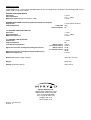
SPECIFICATIONS
All specifications ref. 1Vrms output and 0dBfs digital or 2Vrms analogue input, analogue input sensitivity 0dB, volume
setting -3dB, except where stated.
STEREO ANALOGUE INPUTS
Input level
Input impedance
Maximum input level (input sensitivity –5dB)
2 Vrms
17 kΩ / 100pF
4 Vrms
STEREO ANALOGUE OUTPUTS (Tape REC and Record outputs)
Output level
Output impedance
Tape REC
Record outputs
2 Vrms (same as input)
500 Ω
60 Ω
7.1 CHANNEL ANALOGUE INPUTS
Input level
Input impedance
Maximum input level
1 Vrms
17 kΩ / 100pF
8 Vrms
7.1 CHANNEL LINE OUTPUTS
Output level
Output impedance
Total Harmonic Distortion
Signal-to-noise ratio (A weighted, digital PCM source)
Maximum output level
1 Vrms
60Ω
0.02 %
0.003 %
92 dB
98 dB
98 dB
8 Vrms
Dimensions (width x height x depth)
436 x 95 x 341 mm
Weight
Net 6.0 kg
Voltage (automatic setting)
100 to 240 V
Stereo source
7.1 Channel source
Stereo source
7.1 Channel source
Signal-to-noise ratio (A weighted, analogue sources)
Myryad Systems Ltd.
2 Pipers Wood, Waterberry Drive
Waterlooville, Hants, PO7 7XU
Tel: +44 (0) 23 9226 5508
Fax: +44 (0) 23 9223 1407
[email protected]
www.myryad.co.uk
Stock No: 0ST0012200
Revision: E
19