1
Device Driver Programming
0890425-070
October 1999
Copyright 1999 by Concurrent Computer Corporation. All rights reserved. This publication or any part thereof is
intended for use with Concurrent Computer Corporation products by Concurrent Computer Corporation personnel,
customers, and end–users. It may not be reproduced in any form without the written permission of the publisher.
The information contained in this document is believed to be correct at the time of publication. It is subject to change
without notice. Concurrent Computer Corporation makes no warranties, expressed or implied, concerning the information contained in this document.
To report an error or comment on a specific portion of the manual, photocopy the page in question and mark the correction or comment on the copy. Mail the copy (and any additional comments) to Concurrent Computer Corporation,
2101 W. Cypress Creek Road, Ft. Lauderdale, FL 33309–1892. Mark the envelope “Attention: Publications
Department.” This publication may not be reproduced for any other reason in any form without written permission
of the publisher.
This document is based on copyrighted documentation from Novell, Inc. and is reproduced with permission.
Power Hawk is a trademark of Concurrent Computer Corporation
PowerPC is a trademark of IBM Corporation, used by permission of Motorola, Inc.
Symmetric Superscalar is a trademark of Motorola, Inc.
Night Hawk is a registered trademark of Concurrent Conputer Corporation
UNIX is a registered trademark, licensed exclusively by X/Open Company Ltd.
Printed in U. S. A.
Revision History:
Original Release -- August 1994
Previous Release -- February 1998
Previous Release -- October 1999
Level:
000
060
070
Effective With:
PowerUX 1.1
PowerMAX OS 4.2
PowerMAX OS 4.3
Preface
Scope of Manual
This manual provides reference information and procedures for developing device driver
for all Concurrent systems (except PowerStack) running PowerMAX OS. It focuses only
on development of drivers for character devices.
Structure of Manual
This manual consists of seventeen chapters, one appendix, a glossary, and an index. A
brief description of the chapters is presented as follows:
• Chapter 1 introduces this manual.
• Chapter 2 overviews device drivers.
• Chapter 3 describes the Peripheral Component Interconnect (PCI) Environment
• Chapter 4 describes the Series 6000 hardware environment.
• Chapter 5 describes the Power Hawk Model 610 hardware environment.
• Chapter 6 describes the PowerMAXION hardware environment.
• Chapter 7 describes the Power Hawk Model 620/640 hardware environment.
• Chapter 8 describes the Motorola MCP750 hardware environment.
• Chapter 9 explains the kernel environment.
• Chapter 10 decsribes the procedure for developing a device driver.
• Chapter 11 explains how to multithread device drivers.
• Chapter 12 explains how to support direct memory access (DMA).
• Chapter 13 explains how to dynamically link device drivers to the system.
• Chapter 14 explains driver installation and tuning.
• Chapter 15 explains how to test and debug device drivers.
• Chapter 16 describes the special factors considered when developing
device drivers for real-time or secure systems.
• Chapter 17 discusses how to write a user-level device driver.
• Appendix A provides an example user-level device driver for a National
Instruments PCI DIO-96 card.
iii
Device Driver Programming
The glossary defines technical terms important to understanding the concepts this guide
presents.
The index contains an alphabetical reference to key terms and concepts and the page numbers where they occur in the text.
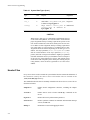
Syntax Notation
This manual uses the following notation:
italic
Books, reference cards, and items that users must specify print in
italic type. Special terms might also print in italic.
list bold
User input prints in list bold type and must match what this
guide shows. Names of directories, files, commands, options and
man page references also print in list bold type.
list
Operating system and program output such as prompts and messages and listings of files and programs print in list type.
[]
Brackets enclose optional arguments and command options for
ease of reading. Actual user input must not include brackets.
Referenced Publications
This manual refers to the following publications:
iv
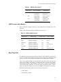
0830047
HN6200 Console Reference Manual
0830044
HN6800 Console Reference Manual
0830050
Motorola SBC Console Reference Manual
0830048
HN6200 Architecture Manual
0830046
HN6800 Architecture Manual
0830053
PowerMAXION Architecture Manual
0890276
HVME Extension Specification
0890423
PowerMAX OS Programming Guide
0890426
STREAMS Modules and Drivers
0890429
System Administration (Volume 1)
0890430
System Administration (Volume 2)
0890431
Audit Trail Administration
0890466
PowerMAX OS Real-Time Guide
0890479
PowerMAX OS Guide to Real-Time Services
Preface
On line
Command Reference
On line
Operating System API Reference
On line
System Files and Devices Reference
On line
Device Driver Reference
v
Device Driver Programming
vi
Contents
Contents
Chapter 1 Introduction
Focus of Manual . . . . . . . . . . . . . . . . . . . . . . . . . . . . . . . . . . . . . . . . . . . . . . . . . . . .
Overview of the Driver Development Effort . . . . . . . . . . . . . . . . . . . . . . . . . . . . . . .
Writing a New Device Driver . . . . . . . . . . . . . . . . . . . . . . . . . . . . . . . . . . . . . . .
Porting an Existing Device Driver . . . . . . . . . . . . . . . . . . . . . . . . . . . . . . . . . . .
Organization of Manual . . . . . . . . . . . . . . . . . . . . . . . . . . . . . . . . . . . . . . . . . . . . . . .
Supporting Documentation . . . . . . . . . . . . . . . . . . . . . . . . . . . . . . . . . . . . . . . . . . . .
1-1
1-1
1-1
1-2
1-2
1-3
Chapter 2 Understanding Device Drivers
What Is a Device Driver?. . . . . . . . . . . . . . . . . . . . . . . . . . . . . . . . . . . . . . . . . . . . . .
Application Programs Versus Drivers . . . . . . . . . . . . . . . . . . . . . . . . . . . . . . . . . . . .
Structure . . . . . . . . . . . . . . . . . . . . . . . . . . . . . . . . . . . . . . . . . . . . . . . . . . . . . . .
Parallel Execution. . . . . . . . . . . . . . . . . . . . . . . . . . . . . . . . . . . . . . . . . . . . . . . .
Interrupts. . . . . . . . . . . . . . . . . . . . . . . . . . . . . . . . . . . . . . . . . . . . . . . . . . . . . . .
Driver As Part of the Kernel . . . . . . . . . . . . . . . . . . . . . . . . . . . . . . . . . . . . . . . .
Types of Devices . . . . . . . . . . . . . . . . . . . . . . . . . . . . . . . . . . . . . . . . . . . . . . . . . . . .
Hardware Devices. . . . . . . . . . . . . . . . . . . . . . . . . . . . . . . . . . . . . . . . . . . . . . . .
Software Devices . . . . . . . . . . . . . . . . . . . . . . . . . . . . . . . . . . . . . . . . . . . . . . . .
Types of Device Driver Interfaces . . . . . . . . . . . . . . . . . . . . . . . . . . . . . . . . . . . . . . .
Block and Character Interfaces . . . . . . . . . . . . . . . . . . . . . . . . . . . . . . . . . . . . .
STREAMS Interface . . . . . . . . . . . . . . . . . . . . . . . . . . . . . . . . . . . . . . . . . . . . .
Major and Minor Numbers . . . . . . . . . . . . . . . . . . . . . . . . . . . . . . . . . . . . . . . . . . . .
Major Numbers. . . . . . . . . . . . . . . . . . . . . . . . . . . . . . . . . . . . . . . . . . . . . . . . . .
Minor Numbers . . . . . . . . . . . . . . . . . . . . . . . . . . . . . . . . . . . . . . . . . . . . . . . . .
Driver Entry Points and Kernel Utilities . . . . . . . . . . . . . . . . . . . . . . . . . . . . . . . . . .
Entry Points . . . . . . . . . . . . . . . . . . . . . . . . . . . . . . . . . . . . . . . . . . . . . . . . . . . .
Initialization Entry Points . . . . . . . . . . . . . . . . . . . . . . . . . . . . . . . . . . . . . .
Switch Table Entry Points . . . . . . . . . . . . . . . . . . . . . . . . . . . . . . . . . . . . . .
Interrupt Entry Points . . . . . . . . . . . . . . . . . . . . . . . . . . . . . . . . . . . . . . . . .
Kernel Support Routines . . . . . . . . . . . . . . . . . . . . . . . . . . . . . . . . . . . . . . . . . .
Driver Environment . . . . . . . . . . . . . . . . . . . . . . . . . . . . . . . . . . . . . . . . . . . . . . . . . .
Installation and Configuration . . . . . . . . . . . . . . . . . . . . . . . . . . . . . . . . . . . . . .
Master, System, and Sadapters Files . . . . . . . . . . . . . . . . . . . . . . . . . . . . . . . . .
Master File. . . . . . . . . . . . . . . . . . . . . . . . . . . . . . . . . . . . . . . . . . . . . . . . . .
System File . . . . . . . . . . . . . . . . . . . . . . . . . . . . . . . . . . . . . . . . . . . . . . . . .
Sadapters File . . . . . . . . . . . . . . . . . . . . . . . . . . . . . . . . . . . . . . . . . . . . . . .
Driver Header Files . . . . . . . . . . . . . . . . . . . . . . . . . . . . . . . . . . . . . . . . . . . . . .
Driver Development. . . . . . . . . . . . . . . . . . . . . . . . . . . . . . . . . . . . . . . . . . . . . . . . . .
2-1
2-2
2-2
2-3
2-3
2-4
2-5
2-5
2-5
2-6
2-6
2-6
2-7
2-7
2-7
2-7
2-7
2-8
2-8
2-10
2-10
2-10
2-10
2-11
2-11
2-12
2-12
2-12
2-12
Chapter 3 The PCI Environment
Introduction . . . . . . . . . . . . . . . . . . . . . . . . . . . . . . . . . . . . . . . . . . . . . . . . . . . . . . . .
PCI Variants and Form Factors . . . . . . . . . . . . . . . . . . . . . . . . . . . . . . . . . . . . . . . . .
Big Vs Little Endian Issues . . . . . . . . . . . . . . . . . . . . . . . . . . . . . . . . . . . . . . . . . . . .
RISC Vs CISC CPU Processor Issues . . . . . . . . . . . . . . . . . . . . . . . . . . . . . . . . . . . .
Types of PCI Resources. . . . . . . . . . . . . . . . . . . . . . . . . . . . . . . . . . . . . . . . . . . . . . .
3-1
3-1
3-2
3-3
3-3
vii
Device Driver Programming
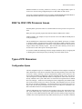
Configuration Space . . . . . . . . . . . . . . . . . . . . . . . . . . . . . . . . . . . . . . . . . . . . . .
Base Address Registers(BAR) . . . . . . . . . . . . . . . . . . . . . . . . . . . . . . . . . . . . . .
Decode into I/O Space . . . . . . . . . . . . . . . . . . . . . . . . . . . . . . . . . . . . . . . . .
Decode into Memory Space. . . . . . . . . . . . . . . . . . . . . . . . . . . . . . . . . . . . .
ROM Base Address Registers(BAR) . . . . . . . . . . . . . . . . . . . . . . . . . . . . . . . . .
Decode into Memory Space. . . . . . . . . . . . . . . . . . . . . . . . . . . . . . . . . . . . .
Interrupts . . . . . . . . . . . . . . . . . . . . . . . . . . . . . . . . . . . . . . . . . . . . . . . . . . .
System Memory and PCI bus Master Devices . . . . . . . . . . . . . . . . . . . . . .
Effects of PCI to PCI Bridges . . . . . . . . . . . . . . . . . . . . . . . . . . . . . . . . . . . . . . .
PowerMax OS Support . . . . . . . . . . . . . . . . . . . . . . . . . . . . . . . . . . . . . . . . . . . . . . .
Finding the Correct Adapter Structure . . . . . . . . . . . . . . . . . . . . . . . . . . . . . . . .
Accessing the Configuration Space Registers. . . . . . . . . . . . . . . . . . . . . . . . . . .
Getting/Releasing the Base Address Register Assignments. . . . . . . . . . . . . . . .
Determining the Kernel Virtual Address of PCI Base Address Register . . . . . .
Accessing PCI Device Registers and Memory Space
Though Kernel Virtual Maps . . . . . . . . . . . . . . . . . . . . . . . . . . . . . . . . . . . . . . .
Determining PCI Memory Address of Particular System Memory
Location . . . . . . . . . . . . . . . . . . . . . . . . . . . . . . . . . . . . . . . . . . . . . . . . . . . . . . .
Attaching and Releasing a PCI Interrupt Vector Assigned to a
PCI Slot/Function . . . . . . . . . . . . . . . . . . . . . . . . . . . . . . . . . . . . . . . . . . . . . . . .
3-3
3-4
3-4
3-4
3-5
3-5
3-5
3-5
3-5
3-5
3-6
3-6
3-6
3-6
3-7
3-7
3-7
Chapter 4 Series 6000 Hardware Environment
System Overview . . . . . . . . . . . . . . . . . . . . . . . . . . . . . . . . . . . . . . . . . . . . . . . . . . . .
Processor Board . . . . . . . . . . . . . . . . . . . . . . . . . . . . . . . . . . . . . . . . . . . . . . . . .
Caches . . . . . . . . . . . . . . . . . . . . . . . . . . . . . . . . . . . . . . . . . . . . . . . . . . . . .
Memory. . . . . . . . . . . . . . . . . . . . . . . . . . . . . . . . . . . . . . . . . . . . . . . . . . . . . . . .
Buses . . . . . . . . . . . . . . . . . . . . . . . . . . . . . . . . . . . . . . . . . . . . . . . . . . . . . . . . . .
Data Types . . . . . . . . . . . . . . . . . . . . . . . . . . . . . . . . . . . . . . . . . . . . . . . . . . . . .
Byte-Ordering and Alignment . . . . . . . . . . . . . . . . . . . . . . . . . . . . . . . . . . . . . .
(H)VME Addressing . . . . . . . . . . . . . . . . . . . . . . . . . . . . . . . . . . . . . . . . . . . . . . . . .
Transfer Width Support. . . . . . . . . . . . . . . . . . . . . . . . . . . . . . . . . . . . . . . . . . . .
Address Types . . . . . . . . . . . . . . . . . . . . . . . . . . . . . . . . . . . . . . . . . . . . . . . . . . .
Address Modifiers. . . . . . . . . . . . . . . . . . . . . . . . . . . . . . . . . . . . . . . . . . . . . . . .
HVME Address Ranges . . . . . . . . . . . . . . . . . . . . . . . . . . . . . . . . . . . . . . . . . . .
VME Address Ranges. . . . . . . . . . . . . . . . . . . . . . . . . . . . . . . . . . . . . . . . . . . . .
(H)VME Devices as (H)VME Bus Slaves. . . . . . . . . . . . . . . . . . . . . . . . . .
(H)VME Devices as Bus Masters . . . . . . . . . . . . . . . . . . . . . . . . . . . . . . . .
Bus Time-Out . . . . . . . . . . . . . . . . . . . . . . . . . . . . . . . . . . . . . . . . . . . . . . . . . . .
VME Device Address Assignment and Configuration . . . . . . . . . . . . . . . . . . . .
Bus Arbitration. . . . . . . . . . . . . . . . . . . . . . . . . . . . . . . . . . . . . . . . . . . . . . . . . . . . . .
Bus Request Levels. . . . . . . . . . . . . . . . . . . . . . . . . . . . . . . . . . . . . . . . . . . . . . .
Configuring Devices Without BR0 . . . . . . . . . . . . . . . . . . . . . . . . . . . . . . .
Interrupt Request Levels and Priorities . . . . . . . . . . . . . . . . . . . . . . . . . . . . . . . . . . .
Interrupt Lines (Levels) . . . . . . . . . . . . . . . . . . . . . . . . . . . . . . . . . . . . . . . . . . .
Interrupt Vector Generation and Configuration . . . . . . . . . . . . . . . . . . . . . . . . . . . . .
4-1
4-1
4-2
4-3
4-3
4-3
4-4
4-4
4-5
4-5
4-5
4-6
4-6
4-6
4-6
4-8
4-8
4-9
4-9
4-10
4-11
4-11
4-12
Chapter 5 Power Hawk 610 Hardware Environment
System Overview . . . . . . . . . . . . . . . . . . . . . . . . . . . . . . . . . . . . . . . . . . . . . . . . . . . .
Processor Board . . . . . . . . . . . . . . . . . . . . . . . . . . . . . . . . . . . . . . . . . . . . . . . . .
Caches . . . . . . . . . . . . . . . . . . . . . . . . . . . . . . . . . . . . . . . . . . . . . . . . . . . . .
Memory. . . . . . . . . . . . . . . . . . . . . . . . . . . . . . . . . . . . . . . . . . . . . . . . . . . . . . . .
viii
5-1
5-1
5-2
5-3
Contents
Buses. . . . . . . . . . . . . . . . . . . . . . . . . . . . . . . . . . . . . . . . . . . . . . . . . . . . . . . . . .
Timers . . . . . . . . . . . . . . . . . . . . . . . . . . . . . . . . . . . . . . . . . . . . . . . . . . . . . . . . .
Interrupts. . . . . . . . . . . . . . . . . . . . . . . . . . . . . . . . . . . . . . . . . . . . . . . . . . . . . . .
Data Types . . . . . . . . . . . . . . . . . . . . . . . . . . . . . . . . . . . . . . . . . . . . . . . . . . . . .
Byte-Ordering and Alignment . . . . . . . . . . . . . . . . . . . . . . . . . . . . . . . . . . . . . .
VME Addressing . . . . . . . . . . . . . . . . . . . . . . . . . . . . . . . . . . . . . . . . . . . . . . . . . . . .
Transfer Width Support . . . . . . . . . . . . . . . . . . . . . . . . . . . . . . . . . . . . . . . . . . .
Address Types. . . . . . . . . . . . . . . . . . . . . . . . . . . . . . . . . . . . . . . . . . . . . . . . . . .
Address Modifiers . . . . . . . . . . . . . . . . . . . . . . . . . . . . . . . . . . . . . . . . . . . . . . .
VME Address Ranges . . . . . . . . . . . . . . . . . . . . . . . . . . . . . . . . . . . . . . . . . . . .
VME Devices as VME Bus Slaves . . . . . . . . . . . . . . . . . . . . . . . . . . . . . . .
VME Devices as Bus Masters . . . . . . . . . . . . . . . . . . . . . . . . . . . . . . . . . . .
Bus Time-Out . . . . . . . . . . . . . . . . . . . . . . . . . . . . . . . . . . . . . . . . . . . . . . . . . . .
VME Device Address Assignment and Configuration. . . . . . . . . . . . . . . . . . . .
Bus Arbitration . . . . . . . . . . . . . . . . . . . . . . . . . . . . . . . . . . . . . . . . . . . . . . . . . . . . .
Bus Request Levels . . . . . . . . . . . . . . . . . . . . . . . . . . . . . . . . . . . . . . . . . . . . . .
Interrupt Request Levels and Priorities . . . . . . . . . . . . . . . . . . . . . . . . . . . . . . . . . . .
Interrupt Lines (Levels) . . . . . . . . . . . . . . . . . . . . . . . . . . . . . . . . . . . . . . . . . . .
Interrupt Vector Generation and Configuration . . . . . . . . . . . . . . . . . . . . . . . . . . . . .
VME to PCI Address Decode . . . . . . . . . . . . . . . . . . . . . . . . . . . . . . . . . . . . . . . . . .
5-3
5-3
5-3
5-4
5-4
5-5
5-5
5-5
5-6
5-6
5-6
5-7
5-7
5-8
5-9
5-9
5-10
5-10
5-11
5-12
Chapter 6 PowerMAXION Hardware Environment
System Overview . . . . . . . . . . . . . . . . . . . . . . . . . . . . . . . . . . . . . . . . . . . . . . . . . . . .
Processor Board . . . . . . . . . . . . . . . . . . . . . . . . . . . . . . . . . . . . . . . . . . . . . . . . .
Caches . . . . . . . . . . . . . . . . . . . . . . . . . . . . . . . . . . . . . . . . . . . . . . . . . . . . .
Memory . . . . . . . . . . . . . . . . . . . . . . . . . . . . . . . . . . . . . . . . . . . . . . . . . . . . . . .
Buses. . . . . . . . . . . . . . . . . . . . . . . . . . . . . . . . . . . . . . . . . . . . . . . . . . . . . . . . . .
Data Types . . . . . . . . . . . . . . . . . . . . . . . . . . . . . . . . . . . . . . . . . . . . . . . . . . . . .
Byte-Ordering and Alignment . . . . . . . . . . . . . . . . . . . . . . . . . . . . . . . . . . . . . .
VME Addressing . . . . . . . . . . . . . . . . . . . . . . . . . . . . . . . . . . . . . . . . . . . . . . . . . . . .
Transfer Width Support . . . . . . . . . . . . . . . . . . . . . . . . . . . . . . . . . . . . . . . . . . .
Address Types. . . . . . . . . . . . . . . . . . . . . . . . . . . . . . . . . . . . . . . . . . . . . . . . . . .
Address Modifiers . . . . . . . . . . . . . . . . . . . . . . . . . . . . . . . . . . . . . . . . . . . . . . .
VME Address Ranges . . . . . . . . . . . . . . . . . . . . . . . . . . . . . . . . . . . . . . . . . . . .
VME Devices as VME Bus Slaves . . . . . . . . . . . . . . . . . . . . . . . . . . . . . . .
VME Devices as Bus Masters . . . . . . . . . . . . . . . . . . . . . . . . . . . . . . . . . . .
Bus Time-Out . . . . . . . . . . . . . . . . . . . . . . . . . . . . . . . . . . . . . . . . . . . . . . . . . . .
VME Device Address Assignment and Configuration. . . . . . . . . . . . . . . . . . . .
Bus Arbitration . . . . . . . . . . . . . . . . . . . . . . . . . . . . . . . . . . . . . . . . . . . . . . . . . . . . .
Bus Request Levels . . . . . . . . . . . . . . . . . . . . . . . . . . . . . . . . . . . . . . . . . . . . . .
Interrupt Request Levels and Priorities . . . . . . . . . . . . . . . . . . . . . . . . . . . . . . . . . . .
Interrupt Lines (Levels) . . . . . . . . . . . . . . . . . . . . . . . . . . . . . . . . . . . . . . . . . . .
Interrupt Vector Generation and Configuration . . . . . . . . . . . . . . . . . . . . . . . . . . . . .
6-1
6-1
6-2
6-3
6-3
6-3
6-4
6-4
6-5
6-5
6-5
6-5
6-6
6-6
6-7
6-8
6-9
6-9
6-9
6-10
6-11
Chapter 7 Power Hawk 620/640 Hardware Environment
System Overview . . . . . . . . . . . . . . . . . . . . . . . . . . . . . . . . . . . . . . . . . . . . . . . . . . . .
Processor Board . . . . . . . . . . . . . . . . . . . . . . . . . . . . . . . . . . . . . . . . . . . . . . . . .
Memory . . . . . . . . . . . . . . . . . . . . . . . . . . . . . . . . . . . . . . . . . . . . . . . . . . . . . . .
Buses. . . . . . . . . . . . . . . . . . . . . . . . . . . . . . . . . . . . . . . . . . . . . . . . . . . . . . . . . .
Timers . . . . . . . . . . . . . . . . . . . . . . . . . . . . . . . . . . . . . . . . . . . . . . . . . . . . . . . . .
Interrupts. . . . . . . . . . . . . . . . . . . . . . . . . . . . . . . . . . . . . . . . . . . . . . . . . . . . . . .
7-1
7-4
7-4
7-4
7-5
7-5
ix
Device Driver Programming
Data Types . . . . . . . . . . . . . . . . . . . . . . . . . . . . . . . . . . . . . . . . . . . . . . . . . . . . .
Byte-Ordering and Alignment . . . . . . . . . . . . . . . . . . . . . . . . . . . . . . . . . . . . . .
VME Addressing . . . . . . . . . . . . . . . . . . . . . . . . . . . . . . . . . . . . . . . . . . . . . . . . . . . .
Transfer Width Support. . . . . . . . . . . . . . . . . . . . . . . . . . . . . . . . . . . . . . . . . . . .
Address Types . . . . . . . . . . . . . . . . . . . . . . . . . . . . . . . . . . . . . . . . . . . . . . . . . . .
Address Modifiers. . . . . . . . . . . . . . . . . . . . . . . . . . . . . . . . . . . . . . . . . . . . . . . .
VME Address Ranges. . . . . . . . . . . . . . . . . . . . . . . . . . . . . . . . . . . . . . . . . . . . .
VME Devices as VME Bus Slaves . . . . . . . . . . . . . . . . . . . . . . . . . . . . . . .
VME Devices as Bus Masters . . . . . . . . . . . . . . . . . . . . . . . . . . . . . . . . . . .
Bus Time-Out . . . . . . . . . . . . . . . . . . . . . . . . . . . . . . . . . . . . . . . . . . . . . . . . . . .
VME Device Address Assignment and Configuration . . . . . . . . . . . . . . . . . . . .
Bus Arbitration. . . . . . . . . . . . . . . . . . . . . . . . . . . . . . . . . . . . . . . . . . . . . . . . . . . . . .
Bus Request Levels. . . . . . . . . . . . . . . . . . . . . . . . . . . . . . . . . . . . . . . . . . . . . . .
Interrupt Request Levels and Priorities . . . . . . . . . . . . . . . . . . . . . . . . . . . . . . . . . . .
Interrupt Lines (Levels) . . . . . . . . . . . . . . . . . . . . . . . . . . . . . . . . . . . . . . . . . . .
Interrupt Vector Generation and Configuration . . . . . . . . . . . . . . . . . . . . . . . . . . . . .
PCI Address Decode . . . . . . . . . . . . . . . . . . . . . . . . . . . . . . . . . . . . . . . . . . . . . . . . .
7-5
7-6
7-7
7-7
7-7
7-7
7-8
7-8
7-8
7-9
7-10
7-10
7-11
7-11
7-11
7-12
7-13
Chapter 8 Motorola MCP750 Hardware Environment
SYSTEM OVERVIEW . . . . . . . . . . . . . . . . . . . . . . . . . . . . . . . . . . . . . . . . . . . . . . .
PROCESSOR BOARD . . . . . . . . . . . . . . . . . . . . . . . . . . . . . . . . . . . . . . . . . . . . . . .
MEMORY . . . . . . . . . . . . . . . . . . . . . . . . . . . . . . . . . . . . . . . . . . . . . . . . . . . . . . . . .
BUSSES . . . . . . . . . . . . . . . . . . . . . . . . . . . . . . . . . . . . . . . . . . . . . . . . . . . . . . . . . . .
TIMERS . . . . . . . . . . . . . . . . . . . . . . . . . . . . . . . . . . . . . . . . . . . . . . . . . . . . . . . . . . .
INTERRUPTS . . . . . . . . . . . . . . . . . . . . . . . . . . . . . . . . . . . . . . . . . . . . . . . . . . . . . .
DATA TYPES . . . . . . . . . . . . . . . . . . . . . . . . . . . . . . . . . . . . . . . . . . . . . . . . . . . . . .
BYTE-ORDERING AND ALIGNMENT. . . . . . . . . . . . . . . . . . . . . . . . . . . . . . . . .
Byte-Ordering and Alignment . . . . . . . . . . . . . . . . . . . . . . . . . . . . . . . . . . . . . .
8-1
8-1
8-2
8-4
8-4
8-4
8-5
8-5
8-5
Chapter 9 Understanding the Kernel Environment
Overview of the Kernel I/O Structure and Flow of Control. . . . . . . . . . . . . . . . . . . .
Overview of Source Directories and Files . . . . . . . . . . . . . . . . . . . . . . . . . . . . . . . . .
System Data Structures . . . . . . . . . . . . . . . . . . . . . . . . . . . . . . . . . . . . . . . . . . . . . . .
Data Types . . . . . . . . . . . . . . . . . . . . . . . . . . . . . . . . . . . . . . . . . . . . . . . . . . . . .
Header Files . . . . . . . . . . . . . . . . . . . . . . . . . . . . . . . . . . . . . . . . . . . . . . . . . . . .
The cdevsw Structure . . . . . . . . . . . . . . . . . . . . . . . . . . . . . . . . . . . . . . . . . . . . .
The cred Structure. . . . . . . . . . . . . . . . . . . . . . . . . . . . . . . . . . . . . . . . . . . . . . . .
The iovec and uio Structures. . . . . . . . . . . . . . . . . . . . . . . . . . . . . . . . . . . . . . . .
The adapter Structure . . . . . . . . . . . . . . . . . . . . . . . . . . . . . . . . . . . . . . . . . . . . .
The device Structure . . . . . . . . . . . . . . . . . . . . . . . . . . . . . . . . . . . . . . . . . . . . . .
Kernel Support Routines . . . . . . . . . . . . . . . . . . . . . . . . . . . . . . . . . . . . . . . . . . . . . .
Ioctl Macros . . . . . . . . . . . . . . . . . . . . . . . . . . . . . . . . . . . . . . . . . . . . . . . . . . . .
Memory Allocation and Management Routines . . . . . . . . . . . . . . . . . . . . . . . . .
Memory Access Routines . . . . . . . . . . . . . . . . . . . . . . . . . . . . . . . . . . . . . . . . . .
Address Management Routines . . . . . . . . . . . . . . . . . . . . . . . . . . . . . . . . . . . . .
Data Transfer Routines . . . . . . . . . . . . . . . . . . . . . . . . . . . . . . . . . . . . . . . . . . . .
Synchronization Routines . . . . . . . . . . . . . . . . . . . . . . . . . . . . . . . . . . . . . . . . . .
Spin Locks . . . . . . . . . . . . . . . . . . . . . . . . . . . . . . . . . . . . . . . . . . . . . . . . . .
Sleep Locks . . . . . . . . . . . . . . . . . . . . . . . . . . . . . . . . . . . . . . . . . . . . . . . . .
Event Synchronization Primitives . . . . . . . . . . . . . . . . . . . . . . . . . . . . . . . .
Processor Priority Level Adjustment Routines. . . . . . . . . . . . . . . . . . . . . . . . . .
x
9-1
9-2
9-3
9-3
9-4
9-5
9-7
9-7
9-9
9-12
9-12
9-12
9-13
9-15
9-15
9-16
9-17
9-17
9-18
9-18
9-18
Contents
Timing and Timeout Routines . . . . . . . . . . . . . . . . . . . . . . . . . . . . . . . . . . . . . .
Interrupt Vector Routines . . . . . . . . . . . . . . . . . . . . . . . . . . . . . . . . . . . . . . . . . .
Debug Routines . . . . . . . . . . . . . . . . . . . . . . . . . . . . . . . . . . . . . . . . . . . . . . . . .
Small vs. Large Offset Drivers . . . . . . . . . . . . . . . . . . . . . . . . . . . . . . . . . . . . . .
9-19
9-20
9-21
9-21
Chapter 10 Developing a Device Driver
Understanding the Device . . . . . . . . . . . . . . . . . . . . . . . . . . . . . . . . . . . . . . . . . . . . .
Device Modes . . . . . . . . . . . . . . . . . . . . . . . . . . . . . . . . . . . . . . . . . . . . . . . . . . .
Configuration Modes . . . . . . . . . . . . . . . . . . . . . . . . . . . . . . . . . . . . . . . . . . . . .
Device Registers . . . . . . . . . . . . . . . . . . . . . . . . . . . . . . . . . . . . . . . . . . . . . . . . .
Command Sequences . . . . . . . . . . . . . . . . . . . . . . . . . . . . . . . . . . . . . . . . . . . . .
DMA Support . . . . . . . . . . . . . . . . . . . . . . . . . . . . . . . . . . . . . . . . . . . . . . . . . . .
Programmed I/O Support . . . . . . . . . . . . . . . . . . . . . . . . . . . . . . . . . . . . . . . . . .
Data Chaining Support . . . . . . . . . . . . . . . . . . . . . . . . . . . . . . . . . . . . . . . . . . . .
Installing and Testing the Device. . . . . . . . . . . . . . . . . . . . . . . . . . . . . . . . . . . . . . . .
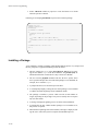
Installing the Device . . . . . . . . . . . . . . . . . . . . . . . . . . . . . . . . . . . . . . . . . . . . .
Using the Console Processor to Probe the Device . . . . . . . . . . . . . . . . . . . . . . .
Validating Slave Address Configurations with the Console Processor . . . .
Validating Master Address Configurations with the Console Processor. . .
Understanding the Major Components of a Device Driver . . . . . . . . . . . . . . . . . . . .
Initialization Routines . . . . . . . . . . . . . . . . . . . . . . . . . . . . . . . . . . . . . . . . . . . .
I/O Service Routines . . . . . . . . . . . . . . . . . . . . . . . . . . . . . . . . . . . . . . . . . . . . .
Interrupt Service Routines . . . . . . . . . . . . . . . . . . . . . . . . . . . . . . . . . . . . . . . . .
Developing the Driver Header File and Data Structures . . . . . . . . . . . . . . . . . . . . . .
Developing the Driver Source File . . . . . . . . . . . . . . . . . . . . . . . . . . . . . . . . . . . . . .
Initialization Routines . . . . . . . . . . . . . . . . . . . . . . . . . . . . . . . . . . . . . . . . . . . .
The Init Routine . . . . . . . . . . . . . . . . . . . . . . . . . . . . . . . . . . . . . . . . . . . . .
The Start Routine . . . . . . . . . . . . . . . . . . . . . . . . . . . . . . . . . . . . . . . . . . . .
I/O Service Routines. . . . . . . . . . . . . . . . . . . . . . . . . . . . . . . . . . . . . . . . . . . . . .
The Open Routine . . . . . . . . . . . . . . . . . . . . . . . . . . . . . . . . . . . . . . . . . . . .
The Close Routine. . . . . . . . . . . . . . . . . . . . . . . . . . . . . . . . . . . . . . . . . . . .
The Read Routine . . . . . . . . . . . . . . . . . . . . . . . . . . . . . . . . . . . . . . . . . . . .
The Write Routine . . . . . . . . . . . . . . . . . . . . . . . . . . . . . . . . . . . . . . . . . . . .
The Ioctl Routine. . . . . . . . . . . . . . . . . . . . . . . . . . . . . . . . . . . . . . . . . . . . .
The Chpoll Routine . . . . . . . . . . . . . . . . . . . . . . . . . . . . . . . . . . . . . . . . . . .
The Mmap Routine . . . . . . . . . . . . . . . . . . . . . . . . . . . . . . . . . . . . . . . . . . .
Interrupt Service Routines . . . . . . . . . . . . . . . . . . . . . . . . . . . . . . . . . . . . . . . . .
The Intr Routine . . . . . . . . . . . . . . . . . . . . . . . . . . . . . . . . . . . . . . . . . . . . .
Local Routines . . . . . . . . . . . . . . . . . . . . . . . . . . . . . . . . . . . . . . . . . . . . . . . . . .
Error Handling . . . . . . . . . . . . . . . . . . . . . . . . . . . . . . . . . . . . . . . . . . . . . . . . . .
Blocking Primitives and Signals. . . . . . . . . . . . . . . . . . . . . . . . . . . . . . . . . . . . .
Blocking Primitives and Premature Returns . . . . . . . . . . . . . . . . . . . . . . . . . . .
10-1
10-1
10-1
10-2
10-2
10-2
10-3
10-3
10-3
10-4
10-5
10-5
10-6
10-6
10-7
10-7
10-7
10-7
10-8
10-8
10-9
10-10
10-10
10-11
10-13
10-14
10-16
10-17
10-18
10-19
10-20
10-21
10-22
10-23
10-24
10-25
Chapter 11 Multithreading a Device Driver
The Multithreaded, Preemptive Kernel and Device Drivers . . . . . . . . . . . . . . . . . . . 11-1
Protecting a Device Driver. . . . . . . . . . . . . . . . . . . . . . . . . . . . . . . . . . . . . . . . . . . . . 11-1
Using the Synchronization Primitives . . . . . . . . . . . . . . . . . . . . . . . . . . . . . . . . . . . . 11-4
Spin Locks . . . . . . . . . . . . . . . . . . . . . . . . . . . . . . . . . . . . . . . . . . . . . . . . . . . . . 11-5
Basic Locks . . . . . . . . . . . . . . . . . . . . . . . . . . . . . . . . . . . . . . . . . . . . . . . . . 11-6
Read/Write Locks . . . . . . . . . . . . . . . . . . . . . . . . . . . . . . . . . . . . . . . . . . . . 11-9
Sleep Locks . . . . . . . . . . . . . . . . . . . . . . . . . . . . . . . . . . . . . . . . . . . . . . . . . . . . 11-13
xi
Device Driver Programming
Using Multiple Locks . . . . . . . . . . . . . . . . . . . . . . . . . . . . . . . . . . . . . . . . . . . . . 11-18
Synchronization Variables . . . . . . . . . . . . . . . . . . . . . . . . . . . . . . . . . . . . . . . . . 11-18
Chapter 12
Supporting Direct Memory Access (DMA)
Overview . . . . . . . . . . . . . . . . . . . . . . . . . . . . . . . . . . . . . . . . . . . . . . . . . . . . . . . . . .
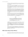
DMA into User Buffers . . . . . . . . . . . . . . . . . . . . . . . . . . . . . . . . . . . . . . . . . . . . . . .
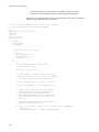
DMA into Discontiguous Physical Memory . . . . . . . . . . . . . . . . . . . . . . . . . . . . . . .
Building a Scatter/Gather Chain List . . . . . . . . . . . . . . . . . . . . . . . . . . . . . . . . . . . . .
24-Bit DMA Devices . . . . . . . . . . . . . . . . . . . . . . . . . . . . . . . . . . . . . . . . . . . . . . . . .
Direct Memory Access to Kernel Space . . . . . . . . . . . . . . . . . . . . . . . . . . . . . . . . . .
12-1
12-1
12-2
12-3
12-5
12-6
Chapter 13 Loadable Modules
The DLM Mechanism . . . . . . . . . . . . . . . . . . . . . . . . . . . . . . . . . . . . . . . . . . . . . . . .
Loadable Module Types . . . . . . . . . . . . . . . . . . . . . . . . . . . . . . . . . . . . . . . . . . .
The Difference between Static Modules and Loadable Modules . . . . . . . . . . . .
Overview of the Load Process . . . . . . . . . . . . . . . . . . . . . . . . . . . . . . . . . . . . . .
Overview of the Unload Process. . . . . . . . . . . . . . . . . . . . . . . . . . . . . . . . . . . . .
The Difference between a Demand Load and an Auto Load . . . . . . . . . . . . . . .
Demand Load. . . . . . . . . . . . . . . . . . . . . . . . . . . . . . . . . . . . . . . . . . . . . . . .
Auto Load . . . . . . . . . . . . . . . . . . . . . . . . . . . . . . . . . . . . . . . . . . . . . . . . . .
Demand Unload . . . . . . . . . . . . . . . . . . . . . . . . . . . . . . . . . . . . . . . . . . . . . .
Auto Unload. . . . . . . . . . . . . . . . . . . . . . . . . . . . . . . . . . . . . . . . . . . . . . . . .
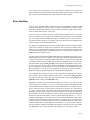
Making Modules Loadable . . . . . . . . . . . . . . . . . . . . . . . . . . . . . . . . . . . . . . . . . . . .
Coding a Wrapper . . . . . . . . . . . . . . . . . . . . . . . . . . . . . . . . . . . . . . . . . . . . . . . .
Wrapper Functions. . . . . . . . . . . . . . . . . . . . . . . . . . . . . . . . . . . . . . . . . . . .
Wrapper Data Structures . . . . . . . . . . . . . . . . . . . . . . . . . . . . . . . . . . . . . . .
Wrapper Macros . . . . . . . . . . . . . . . . . . . . . . . . . . . . . . . . . . . . . . . . . . . . .
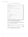
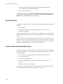
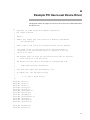
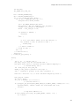
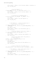
Sample Wrapper Code. . . . . . . . . . . . . . . . . . . . . . . . . . . . . . . . . . . . . . . . .
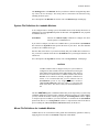
Packaging a Loadable Module for Installation . . . . . . . . . . . . . . . . . . . . . . . . . .
Master File Definitions for Loadable Modules . . . . . . . . . . . . . . . . . . . . . .
System File Definitions for Loadable Modules . . . . . . . . . . . . . . . . . . . . . .
Mtune File Definitions for Loadable Modules . . . . . . . . . . . . . . . . . . . . . .
Installing and Configuring a Loadable Module . . . . . . . . . . . . . . . . . . . . . . . . .
Managing Loadable Modules . . . . . . . . . . . . . . . . . . . . . . . . . . . . . . . . . . . . . . .
Loading the Module. . . . . . . . . . . . . . . . . . . . . . . . . . . . . . . . . . . . . . . . . . .
Querying the Module's Status . . . . . . . . . . . . . . . . . . . . . . . . . . . . . . . . . . .
Modifying the DLM Search Path . . . . . . . . . . . . . . . . . . . . . . . . . . . . . . . .
Unloading the Module . . . . . . . . . . . . . . . . . . . . . . . . . . . . . . . . . . . . . . . . .
Debugging a Loadable Module. . . . . . . . . . . . . . . . . . . . . . . . . . . . . . . . . . . . . .
DLM Error Messages . . . . . . . . . . . . . . . . . . . . . . . . . . . . . . . . . . . . . . . . .
Dynamic Symbols and kdb . . . . . . . . . . . . . . . . . . . . . . . . . . . . . . . . . . . . .
13-2
13-2
13-2
13-3
13-3
13-3
13-3
13-3
13-4
13-4
13-5
13-5
13-5
13-6
13-6
13-7
13-10
13-10
13-11
13-11
13-12
13-12
13-12
13-13
13-13
13-14
13-14
13-14
13-14
Chapter 14 Driver Installation and Tuning
Using idtools . . . . . . . . . . . . . . . . . . . . . . . . . . . . . . . . . . . . . . . . . . . . . . . . . . . . . . .
idtools Utilities and Commands . . . . . . . . . . . . . . . . . . . . . . . . . . . . . . . . . . . . .
idbuild . . . . . . . . . . . . . . . . . . . . . . . . . . . . . . . . . . . . . . . . . . . . . . . . . . . . .
idcheck. . . . . . . . . . . . . . . . . . . . . . . . . . . . . . . . . . . . . . . . . . . . . . . . . . . . .
idinstall . . . . . . . . . . . . . . . . . . . . . . . . . . . . . . . . . . . . . . . . . . . . . . . . . . . .
idmkinit . . . . . . . . . . . . . . . . . . . . . . . . . . . . . . . . . . . . . . . . . . . . . . . . . . . .
idmknod . . . . . . . . . . . . . . . . . . . . . . . . . . . . . . . . . . . . . . . . . . . . . . . . . . . .
xii
14-1
14-1
14-2
14-3
14-3
14-4
14-4
Contents
idspace . . . . . . . . . . . . . . . . . . . . . . . . . . . . . . . . . . . . . . . . . . . . . . . . . . . . .
idtune. . . . . . . . . . . . . . . . . . . . . . . . . . . . . . . . . . . . . . . . . . . . . . . . . . . . . .
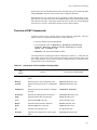
The Driver Software Package (DSP) . . . . . . . . . . . . . . . . . . . . . . . . . . . . . . . . . . . . .
Overview of DSP Components. . . . . . . . . . . . . . . . . . . . . . . . . . . . . . . . . . . . . .
DSP Component Files . . . . . . . . . . . . . . . . . . . . . . . . . . . . . . . . . . . . . . . . . . . .
Sadapters . . . . . . . . . . . . . . . . . . . . . . . . . . . . . . . . . . . . . . . . . . . . . . . . . . .
Driver.o . . . . . . . . . . . . . . . . . . . . . . . . . . . . . . . . . . . . . . . . . . . . . . . . . . . .
Master . . . . . . . . . . . . . . . . . . . . . . . . . . . . . . . . . . . . . . . . . . . . . . . . . . . . .
System . . . . . . . . . . . . . . . . . . . . . . . . . . . . . . . . . . . . . . . . . . . . . . . . . . . . .
Init . . . . . . . . . . . . . . . . . . . . . . . . . . . . . . . . . . . . . . . . . . . . . . . . . . . . . . . .
Mtune . . . . . . . . . . . . . . . . . . . . . . . . . . . . . . . . . . . . . . . . . . . . . . . . . . . . .
Node . . . . . . . . . . . . . . . . . . . . . . . . . . . . . . . . . . . . . . . . . . . . . . . . . . . . . .
Rc . . . . . . . . . . . . . . . . . . . . . . . . . . . . . . . . . . . . . . . . . . . . . . . . . . . . . . . .
Sassign. . . . . . . . . . . . . . . . . . . . . . . . . . . . . . . . . . . . . . . . . . . . . . . . . . . . .
Sd. . . . . . . . . . . . . . . . . . . . . . . . . . . . . . . . . . . . . . . . . . . . . . . . . . . . . . . . .
Space.c. . . . . . . . . . . . . . . . . . . . . . . . . . . . . . . . . . . . . . . . . . . . . . . . . . . . .
Packaging the Driver . . . . . . . . . . . . . . . . . . . . . . . . . . . . . . . . . . . . . . . . . . . . .
prototype . . . . . . . . . . . . . . . . . . . . . . . . . . . . . . . . . . . . . . . . . . . . . . . . . . .
postinstall . . . . . . . . . . . . . . . . . . . . . . . . . . . . . . . . . . . . . . . . . . . . . . . . . .
preremove . . . . . . . . . . . . . . . . . . . . . . . . . . . . . . . . . . . . . . . . . . . . . . . . . .
Installing a Package . . . . . . . . . . . . . . . . . . . . . . . . . . . . . . . . . . . . . . . . . . . . . .
Removing a Package . . . . . . . . . . . . . . . . . . . . . . . . . . . . . . . . . . . . . . . . . . . . .
DSP Commands and Procedures . . . . . . . . . . . . . . . . . . . . . . . . . . . . . . . . . . . . . . . .
Installing a DSP . . . . . . . . . . . . . . . . . . . . . . . . . . . . . . . . . . . . . . . . . . . . . . . . .
Updating a DSP . . . . . . . . . . . . . . . . . . . . . . . . . . . . . . . . . . . . . . . . . . . . . . . . .
Modifying a Kernel Parameter . . . . . . . . . . . . . . . . . . . . . . . . . . . . . . . . . . . . . .
Removing a DSP . . . . . . . . . . . . . . . . . . . . . . . . . . . . . . . . . . . . . . . . . . . . . . . .
Building a New Kernel . . . . . . . . . . . . . . . . . . . . . . . . . . . . . . . . . . . . . . . . . . . .
Emergency Recovery (New Kernel Does Not Boot) . . . . . . . . . . . . . . . . . . . . .
Documenting Your Driver Installation . . . . . . . . . . . . . . . . . . . . . . . . . . . . . . . .
14-5
14-5
14-6
14-7
14-8
14-8
14-9
14-9
14-9
14-10
14-11
14-12
14-12
14-13
14-13
14-14
14-15
14-15
14-16
14-17
14-18
14-19
14-19
14-19
14-20
14-20
14-20
14-21
14-21
14-22
Chapter 15 Driver Testing and Debugging
Introduction . . . . . . . . . . . . . . . . . . . . . . . . . . . . . . . . . . . . . . . . . . . . . . . . . . . . . . . . 15-1
Preparing a Driver for Debugging . . . . . . . . . . . . . . . . . . . . . . . . . . . . . . . . . . . . . . . 15-1
General Guidelines . . . . . . . . . . . . . . . . . . . . . . . . . . . . . . . . . . . . . . . . . . . . . . . 15-2
Putting Debug Statements in a Driver . . . . . . . . . . . . . . . . . . . . . . . . . . . . . . . . 15-2
Installing a Driver for Testing. . . . . . . . . . . . . . . . . . . . . . . . . . . . . . . . . . . . . . . 15-4
Emergency Recovery (New Kernel Does Not Boot). . . . . . . . . . . . . . . . . . 15-4
Common Driver Problems . . . . . . . . . . . . . . . . . . . . . . . . . . . . . . . . . . . . . . . . . . . . . 15-5
Coding Problems . . . . . . . . . . . . . . . . . . . . . . . . . . . . . . . . . . . . . . . . . . . . . . . . 15-5
Installation Problems . . . . . . . . . . . . . . . . . . . . . . . . . . . . . . . . . . . . . . . . . . . . . 15-5
Data Structure Problems. . . . . . . . . . . . . . . . . . . . . . . . . . . . . . . . . . . . . . . . . . . 15-5
Timing Errors . . . . . . . . . . . . . . . . . . . . . . . . . . . . . . . . . . . . . . . . . . . . . . . . . . . 15-6
Corrupted Interrupt Stack . . . . . . . . . . . . . . . . . . . . . . . . . . . . . . . . . . . . . . . . . . 15-6
Accessing Critical Data . . . . . . . . . . . . . . . . . . . . . . . . . . . . . . . . . . . . . . . . . . . 15-6
Overuse of Local Driver Storage . . . . . . . . . . . . . . . . . . . . . . . . . . . . . . . . . . . . 15-6
Incorrect DMA Address Mapping . . . . . . . . . . . . . . . . . . . . . . . . . . . . . . . . . . . 15-6
Driver Debugging Techniques . . . . . . . . . . . . . . . . . . . . . . . . . . . . . . . . . . . . . . . . . . 15-7
Using the Console Processor and Setting Breakpoints. . . . . . . . . . . . . . . . . . . . 15-7
Booting Scenarios . . . . . . . . . . . . . . . . . . . . . . . . . . . . . . . . . . . . . . . . . . . . 15-9
Shutdown and Reboot . . . . . . . . . . . . . . . . . . . . . . . . . . . . . . . . . . . . . . . . . 15-9
System Panic . . . . . . . . . . . . . . . . . . . . . . . . . . . . . . . . . . . . . . . . . . . 15-12
xiii
Device Driver Programming
Breakpoints in the Initialization Phase . . . . . . . . . . . . . . . . . . . . . . . . .
Using crash to Debug a Driver . . . . . . . . . . . . . . . . . . . . . . . . . . . . . . . . . . . . . .
Saving the Core Image of Memory . . . . . . . . . . . . . . . . . . . . . . . . . . . . . . .
Initializing crash on the Memory Dump . . . . . . . . . . . . . . . . . . . . . . . . . . .
Using crash Functions . . . . . . . . . . . . . . . . . . . . . . . . . . . . . . . . . . . . . . . . .
Using crash Commands . . . . . . . . . . . . . . . . . . . . . . . . . . . . . . . . . . . . . . . .
Kernel Debugger . . . . . . . . . . . . . . . . . . . . . . . . . . . . . . . . . . . . . . . . . . . . . . . . .
Entering kdb from a Driver. . . . . . . . . . . . . . . . . . . . . . . . . . . . . . . . . . . . . . . . .
System Panics . . . . . . . . . . . . . . . . . . . . . . . . . . . . . . . . . . . . . . . . . . . . . . . . . . .
15-14
15-16
15-16
15-17
15-17
15-18
15-18
15-19
15-19
Chapter 16 Special Considerations
Device Drivers and Real Time . . . . . . . . . . . . . . . . . . . . . . . . . . . . . . . . . . . . . . . . . .
Device Drivers and VME Bus Errors. . . . . . . . . . . . . . . . . . . . . . . . . . . . . . . . . . . . .
Additional Considerations . . . . . . . . . . . . . . . . . . . . . . . . . . . . . . . . . . . . . . . . .
Device Drivers and Security. . . . . . . . . . . . . . . . . . . . . . . . . . . . . . . . . . . . . . . . . . . .
System Requirements . . . . . . . . . . . . . . . . . . . . . . . . . . . . . . . . . . . . . . . . . . . . .
Design and Implementation Issues . . . . . . . . . . . . . . . . . . . . . . . . . . . . . . . . . . .
16-1
16-2
16-4
16-4
16-4
16-5
Chapter 17 Writing a User-Level Device Driver
Understanding a User-Level Device Driver . . . . . . . . . . . . . . . . . . . . . . . . . . . . . . . .
What Is a User-Level Device Driver? . . . . . . . . . . . . . . . . . . . . . . . . . . . . . . . . .
What Are the Advantages and Disadvantages of a User-Level Driver? . . . . . . .
Which Types of Devices Are Candidates for a User-Level Driver? . . . . . . . . . .
What Affects the Complexity of a User-Level Device Driver? . . . . . . . . . . . . .
Programmed I/O versus Direct Memory Access Devices . . . . . . . . . . . . . .
Single-User Drivers versus Multiuser Drivers. . . . . . . . . . . . . . . . . . . . . . .
Polling Support versus Interrupt Support . . . . . . . . . . . . . . . . . . . . . . . . . .
Understanding the Components of a User-Level Driver . . . . . . . . . . . . . . . . . . . . . .
Overview of Data Structures. . . . . . . . . . . . . . . . . . . . . . . . . . . . . . . . . . . . . . . .
Shared Memory Regions . . . . . . . . . . . . . . . . . . . . . . . . . . . . . . . . . . . . . . .
User I/O Buffer Descriptor . . . . . . . . . . . . . . . . . . . . . . . . . . . . . . . . . . . . .
Overview of User-Level Device Driver Routines . . . . . . . . . . . . . . . . . . . . . . . .
Overview of Interrupt-Handling Issues. . . . . . . . . . . . . . . . . . . . . . . . . . . . . . . .
Overview of Synchronization Issues. . . . . . . . . . . . . . . . . . . . . . . . . . . . . . . . . .
Overview of Error Returns . . . . . . . . . . . . . . . . . . . . . . . . . . . . . . . . . . . . . . . . .
Overview of the Device Configuration Program . . . . . . . . . . . . . . . . . . . . . . . .
Understanding Operating System Support for a User-Level Driver . . . . . . . . . . . . .
The userdma(2) System Call. . . . . . . . . . . . . . . . . . . . . . . . . . . . . . . . . . . . . . . .
The udbufalloc(3X) Library Routine . . . . . . . . . . . . . . . . . . . . . . . . . . . . . . . . .
The udbuffree(3X) Library Routine . . . . . . . . . . . . . . . . . . . . . . . . . . . . . . . . . .
The atexit(3C) Library Routine . . . . . . . . . . . . . . . . . . . . . . . . . . . . . . . . . . . . .
The uderror(3X) Library Routine . . . . . . . . . . . . . . . . . . . . . . . . . . . . . . . . . . . .
The spl Support Routines . . . . . . . . . . . . . . . . . . . . . . . . . . . . . . . . . . . . . . . . . .
Process Synchronization Tools . . . . . . . . . . . . . . . . . . . . . . . . . . . . . . . . . . . . . .
Busy-Wait Mutual Exclusion Tools . . . . . . . . . . . . . . . . . . . . . . . . . . . . . . .
Rescheduling Control Tools. . . . . . . . . . . . . . . . . . . . . . . . . . . . . . . . . . . . .
The Server System Calls . . . . . . . . . . . . . . . . . . . . . . . . . . . . . . . . . . . . . . .
The User-Level Interrupt Library Routines and Utility . . . . . . . . . . . . . . . . . . .
The vme_address(3C) Library Routine . . . . . . . . . . . . . . . . . . . . . . . . . . . . . . .
Developing the Driver’s I/O Service Routines. . . . . . . . . . . . . . . . . . . . . . . . . . . . . .
The open Routine . . . . . . . . . . . . . . . . . . . . . . . . . . . . . . . . . . . . . . . . . . . . . . . .
xiv
17-1
17-1
17-2
17-3
17-3
17-3
17-4
17-4
17-4
17-5
17-6
17-7
17-9
17-11
17-12
17-13
17-14
17-15
17-15
17-16
17-17
17-17
17-18
17-19
17-19
17-20
17-20
17-21
17-22
17-23
17-23
17-23
Contents
The Asynchronous I/O Support Routines. . . . . . . . . . . . . . . . . . . . . . . . . . . . . .
The aread Routine . . . . . . . . . . . . . . . . . . . . . . . . . . . . . . . . . . . . . . . . . . . .
The awrite Routine . . . . . . . . . . . . . . . . . . . . . . . . . . . . . . . . . . . . . . . . . . .
The acheck Routine . . . . . . . . . . . . . . . . . . . . . . . . . . . . . . . . . . . . . . . . . . .
The await Routine . . . . . . . . . . . . . . . . . . . . . . . . . . . . . . . . . . . . . . . . . . . .
Control Functions . . . . . . . . . . . . . . . . . . . . . . . . . . . . . . . . . . . . . . . . . . . . . . . .
The close Routine . . . . . . . . . . . . . . . . . . . . . . . . . . . . . . . . . . . . . . . . . . . . . . . .
Developing the Driver’s Interrupt Service Routine . . . . . . . . . . . . . . . . . . . . . . . . . .
Connecting a User-Level Interrupt Process and Interrupt Vector. . . . . . . . . . . .
User-Level Interrupts and Memory Locking . . . . . . . . . . . . . . . . . . . . . . . . . . .
Use of Local Memory. . . . . . . . . . . . . . . . . . . . . . . . . . . . . . . . . . . . . . . . . . . . .
Constraints on Interrupt-Handling Routines . . . . . . . . . . . . . . . . . . . . . . . . . . .
Developing the Device Configuration Program. . . . . . . . . . . . . . . . . . . . . . . . . . . . .
Create Shared Memory Regions and Initialize the Device. . . . . . . . . . . . . . . . .
Reset the Device . . . . . . . . . . . . . . . . . . . . . . . . . . . . . . . . . . . . . . . . . . . . . . . . .
Create a User-Level Interrupt Process . . . . . . . . . . . . . . . . . . . . . . . . . . . . . . . .
Provide Debug and Status Information . . . . . . . . . . . . . . . . . . . . . . . . . . . . . . .
Restore the Device to its Initial State . . . . . . . . . . . . . . . . . . . . . . . . . . . . . . . . .
Debugging the Driver . . . . . . . . . . . . . . . . . . . . . . . . . . . . . . . . . . . . . . . . . . . . . . . .
17-25
17-26
17-27
17-28
17-29
17-30
17-31
17-34
17-34
17-36
17-36
17-37
17-38
17-39
17-40
17-40
17-41
17-41
17-41
Appendix A Example PCI User-Level Device Driver
Glossary
Index
Illustrations
Figure 2-1. Driver Placement in the Kernel . . . . . . . . . . . . . . . . . . . . . . . . . . . . . . .
Figure 2-2. How the System Calls Driver Routines . . . . . . . . . . . . . . . . . . . . . . . . .
Figure 2-3. Switch Table Entry Points and System Calls . . . . . . . . . . . . . . . . . . . . .
Figure 4-1. Elements of an HN6800 Processor Board . . . . . . . . . . . . . . . . . . . . . . .
Figure 4-2. Big Endian Bit and Byte Notation . . . . . . . . . . . . . . . . . . . . . . . . . . . .
Figure 5-1. Elements of a Power Hawk PH610 Processor Board . . . . . . . . . . . . . .
Figure 5-2. Big Endian Bit and Byte Notation . . . . . . . . . . . . . . . . . . . . . . . . . . . .
Figure 6-1. Elements of a PowerMAXION Processor Board. . . . . . . . . . . . . . . . . .
Figure 6-2. Big Endian Bit and Byte Notation . . . . . . . . . . . . . . . . . . . . . . . . . . . .
Figure 7-1. Elements of an Power Hawk 620 Processor Board . . . . . . . . . . . . . . . .
Figure 7-2. Power Hawk 640 System Block Diagram . . . . . . . . . . . . . . . . . . . . . . .
Figure 7-3. Big Endian Bit and Byte Notation . . . . . . . . . . . . . . . . . . . . . . . . . . . .
Figure 8-1. Motorola MCP750 System Block Diagram. . . . . . . . . . . . . . . . . . . . . .
Figure 8-2. Big Endian Bit and Byte Notation . . . . . . . . . . . . . . . . . . . . . . . . . . . .
Figure 9-1. Kernel I/O Structure. . . . . . . . . . . . . . . . . . . . . . . . . . . . . . . . . . . . . . . .
Figure 10-1. Installing (H)VME Board into 13-slot Rack . . . . . . . . . . . . . . . . . . . .
2-2
2-3
2-9
4-2
4-4
5-2
5-5
6-2
6-4
7-2
7-3
7-6
8-3
8-6
9-2
10-4
Screen 13-1.
Screen 13-2.
Screen 13-3.
Screen 13-4.
Screen 13-5.
13-7
13-8
13-8
13-9
13-9
Screens
Device Driver Wrapper Coding Example . . . . . . . . . . . . . . . . . . . . . .
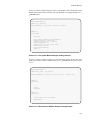
High Level Driver Wrapper Coding Example. . . . . . . . . . . . . . . . . . .
STREAMS Module Wrapper Coding Example . . . . . . . . . . . . . . . . .
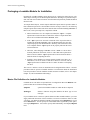
File System Module Wrapper Coding Example . . . . . . . . . . . . . . . . .
Miscellaneous Module Wrapper Coding Example . . . . . . . . . . . . . . .
xv
Device Driver Programming
Tables
Table 4-1. HVME Address Range . . . . . . . . . . . . . . . . . . . . . . . . . . . . . . . . . . . . . .
4-6
Table 4-2. HVME Bus Slave Access. . . . . . . . . . . . . . . . . . . . . . . . . . . . . . . . . . . . .
4-6
Table 4-3. HVME Bus Master Access . . . . . . . . . . . . . . . . . . . . . . . . . . . . . . . . . . .
4-7
Table 5-1. VME Bus Slave Access . . . . . . . . . . . . . . . . . . . . . . . . . . . . . . . . . . . . . .
5-7
Table 5-2. VME Bus Master Access . . . . . . . . . . . . . . . . . . . . . . . . . . . . . . . . . . . . .
5-7
Table 5-3. VME to PCI Address Decode Register . . . . . . . . . . . . . . . . . . . . . . . . . . 5-12
Table 6-1. VME Bus Slave Access . . . . . . . . . . . . . . . . . . . . . . . . . . . . . . . . . . . . . .
6-6
Table 6-2. VME Bus Master Access . . . . . . . . . . . . . . . . . . . . . . . . . . . . . . . . . . . .
6-6
Table 7-1. Default VME Bus Slave Access . . . . . . . . . . . . . . . . . . . . . . . . . . . . . . .
7-8
Table 7-2. VME Bus Master Access . . . . . . . . . . . . . . . . . . . . . . . . . . . . . . . . . . . . .
7-9
Table 7-3. Default PCI Address Decode . . . . . . . . . . . . . . . . . . . . . . . . . . . . . . . . . . 7-14
Table 9-1. System Data Types . . . . . . . . . . . . . . . . . . . . . . . . . . . . . . . . . . . . . . . . .
9-3
Table 9-2. Fields in ioctl Command . . . . . . . . . . . . . . . . . . . . . . . . . . . . . . . . . . . . . 9-13
Table 14-1. Components of Driver Software Package (DSP) . . . . . . . . . . . . . . . . . 14-7
Table 15-1. Console Processor Commands. . . . . . . . . . . . . . . . . . . . . . . . . . . . . . . . 15-8
Table 15-2. Important Parameters to the p Console Processor Command . . . . . . . . 15-9
Table 16-1. User-Level Device Driver Error Codes and Messages . . . . . . . . . . . . . 17-13
xvi
1
Introduction
Focus of Manual . . . . . . . . . . . . . . . . . . . . . . . . . . . . . . . . . . . . . . . . . . . . . . . . . . . .
Overview of the Driver Development Effort . . . . . . . . . . . . . . . . . . . . . . . . . . . . . . .
Writing a New Device Driver . . . . . . . . . . . . . . . . . . . . . . . . . . . . . . . . . . . . . . .
Porting an Existing Device Driver . . . . . . . . . . . . . . . . . . . . . . . . . . . . . . . . . . .
Organization of Manual . . . . . . . . . . . . . . . . . . . . . . . . . . . . . . . . . . . . . . . . . . . . . . .
Supporting Documentation . . . . . . . . . . . . . . . . . . . . . . . . . . . . . . . . . . . . . . . . . . . .
1-1
1-1
1-1
1-2
1-2
1-3
Device Driver Programming
1
Chapter 1Introduction
1
1
1
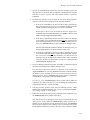
This chapter defines the scope of this manual and overviews the effort required to develop
a device driver for PowerMAX OS. It describes the PowerMAX OS manuals potentially
needed to develop a device driver.
Focus of Manual
1
This document is written for programmers with experience in writing device drivers and
using UNIX® operating systems. It focuses on device driver development for Concurrent
Computer Corporation hardware and the PowerMAX OS.
Information related specifically to hardware resides in Chapters 4-8.
Note that the information this document contains reflects the current status of the operating system internals and the interface between the kernel and a device driver. Some of the
internals and the driver interface might change with future development and subsequent
releases of the operating system.
The explanations this document presents focus on developing drivers for character, or
unstructured, devices. Such devices include programmed I/O devices and direct memory
access (DMA) devices.
Overview of the Driver Development Effort
1
This section introduces the steps involved in developing a device driver. First, it outlines
the steps required to write a new device driver. Then, it addresses the effort involved in
porting an existing driver to a PowerMAX OS system.
Writing a New Device Driver
1
Before developing a driver for a device to add to the system, become familiar with the
hardware environment, kernel environment, kernel-to-driver interface, and the device
itself. Chapters 4-7 provide the hardware information. Chapter 9 provides the kernel environment information. Chapter 10 provides device evaluation and operation information.
Understanding these topics helps undertake the major tasks of integrating a device and its
drivers into the system:
1. Install the device and test to see if it works.
1-1
Device Driver Programming
2. Design the driver.
3. Write the driver.
4. Integrate the driver into the system
5. Test and debug the driver.
Procedures for installing and testing the device and developing the driver component of
the driver reside in Chapter 10. Procedures for integrating the driver into the system reside
in Chapter 14. Techniques for debugging the driver reside in Chapter 15.
Three phases constitute the driver development process:
1. Design
2. Development
3. Testing.
The time needed to develop a device driver depends upon the following factors:
• Programmer experience
• Device functions
• Device driver complexity
• Tools available
Porting an Existing Device Driver
1
Porting an existing driver to a PowerMAX OS system needs the same basic understandings to develop a new driver: understanding the hardware, the kernel and its interface to
device drivers, and the device. To incorporate the device and its drivers in the system, you
also must do most of the major tasks previously outlined; instead of having to design and
write the driver, you must analyze the difference in architectures, operating system, and
driver interface and modify the driver accordingly.
Porting an existing driver is quicker than developing a new one.
Organization of Manual
1
This manual presents information in the approximate order required by the development
process.
Chapter 2 overviews device drivers, explains the classes of devices and how to identify
them, and describes the interface between a device driver and the kernel.
Chapter 3 covers various aspects of the PCI environment as supported by PowerMAX running on Motorola-based platforms.
1-2
Introduction
Chapters 4-8 describe the hardware environments, briefly overview the platform and then
provide more information on configuring and operating each system.
Chapter 9 explains the kernel environment. It describes the kernel I/O structure and flow
of control and maps the system source directories and files important to driver development. It also details the system data structures and kernel support routines pertinent to
driver development.
Chapter 10 guides you in understanding the device supported by the driver, and explains
how to install and test the device. It also explains the structure and components of a device
driver and how to develop the code.
Chapter 11 explains how to protect a device driver in a multiprocessor system.
Chapter 12 explains how to support direct memory access (DMA).
Chapter 13 explains how to dynamically link a device driver to the system.
Chapter 14 explains how to integrate a device driver into the system. It contains step-bystep procedures to modify the system files, configure the system, build the kernel, and create the device special files. It also details the tools to install and configure driver software.
Chapter 15 explains how to test and debug a device driver. It describes common driver
problems and driver debugging techniques.
Chapter 16 describes the special factors to consider when developing a device driver for a
real-time production environment. It also overviews security issues affecting development
of a device driver for the PowerMAX OS system.
Chapter 17 discusses writing a user-level device driver.
Supporting Documentation
1
This section introduces the other manuals designed to provide additional detailed information on the operating system and hardware.
Device Driver Reference
On-line manual pages containing reference information on the PowerMAX OS
Device Driver Interface (DDI) and Driver Kernel Interface (DKI).
STREAMS Modules and Drivers (Pub. No. 0890426)
Explains how to use the STREAMS mechanism for PowerMAX OS system communication services.
PowerMAX OS Programming Guide (Pub. No. 0890423)
Explains how to use the system services supplied by PowerMAX OS.
1-3
Device Driver Programming
PowerMAX OS Real-Time Guide (Pub. No. 0890466)
Explains user-level interrupt routines and inter-process synchronization on PowerMAX OS.
System Administration, Volume 1 (Pub. No. 0890429)
System Administration, Volume 2 (Pub. No. 0890430)
Designed to help system administrators, these explain how to set up, configure, and
maintain the operating system. Volume 1 explains system set-up, configuration, and
security administration. Volume 2 explains file system administration, performance
management, backup and restore services, print service administration, and the
sysadm interface.
HVME Extension Specification (Pub. No. 0890276)
Describes the extensions to the standard VMEbus used by Concurrent Computer
Corporation VME (HVME) boards. These provide a larger board size, more power
pins, fast synchronous burst mode, and bus parity.
PCI System Architecture, MindShare, Inc. - ISBN: 0-201-40993-3
Describes the Peripheral Componet Interconnect (PCI) bus specification.
1-4
2
Understanding Device Drivers
What Is a Device Driver?. . . . . . . . . . . . . . . . . . . . . . . . . . . . . . . . . . . . . . . . . . . . . .
Application Programs Versus Drivers . . . . . . . . . . . . . . . . . . . . . . . . . . . . . . . . . . . .
Structure . . . . . . . . . . . . . . . . . . . . . . . . . . . . . . . . . . . . . . . . . . . . . . . . . . . . . . .
Parallel Execution. . . . . . . . . . . . . . . . . . . . . . . . . . . . . . . . . . . . . . . . . . . . . . . .
Interrupts. . . . . . . . . . . . . . . . . . . . . . . . . . . . . . . . . . . . . . . . . . . . . . . . . . . . . . .
Driver As Part of the Kernel . . . . . . . . . . . . . . . . . . . . . . . . . . . . . . . . . . . . . . . .
Types of Devices . . . . . . . . . . . . . . . . . . . . . . . . . . . . . . . . . . . . . . . . . . . . . . . . . . . .
Hardware Devices. . . . . . . . . . . . . . . . . . . . . . . . . . . . . . . . . . . . . . . . . . . . . . . .
Software Devices . . . . . . . . . . . . . . . . . . . . . . . . . . . . . . . . . . . . . . . . . . . . . . . .
Types of Device Driver Interfaces . . . . . . . . . . . . . . . . . . . . . . . . . . . . . . . . . . . . . . .
Block and Character Interfaces . . . . . . . . . . . . . . . . . . . . . . . . . . . . . . . . . . . . .
STREAMS Interface . . . . . . . . . . . . . . . . . . . . . . . . . . . . . . . . . . . . . . . . . . . . .
Major and Minor Numbers . . . . . . . . . . . . . . . . . . . . . . . . . . . . . . . . . . . . . . . . . . . .
Major Numbers. . . . . . . . . . . . . . . . . . . . . . . . . . . . . . . . . . . . . . . . . . . . . . . . . .
Minor Numbers . . . . . . . . . . . . . . . . . . . . . . . . . . . . . . . . . . . . . . . . . . . . . . . . .
Driver Entry Points and Kernel Utilities . . . . . . . . . . . . . . . . . . . . . . . . . . . . . . . . . .
Entry Points . . . . . . . . . . . . . . . . . . . . . . . . . . . . . . . . . . . . . . . . . . . . . . . . . . . .
Initialization Entry Points . . . . . . . . . . . . . . . . . . . . . . . . . . . . . . . . . . . . . .
Switch Table Entry Points . . . . . . . . . . . . . . . . . . . . . . . . . . . . . . . . . . . . . .
Interrupt Entry Points . . . . . . . . . . . . . . . . . . . . . . . . . . . . . . . . . . . . . . . . .
Kernel Support Routines . . . . . . . . . . . . . . . . . . . . . . . . . . . . . . . . . . . . . . . . . .
Driver Environment . . . . . . . . . . . . . . . . . . . . . . . . . . . . . . . . . . . . . . . . . . . . . . . . . .
Installation and Configuration . . . . . . . . . . . . . . . . . . . . . . . . . . . . . . . . . . . . . .
Master, System, and Sadapters Files . . . . . . . . . . . . . . . . . . . . . . . . . . . . . . . . .
Master File. . . . . . . . . . . . . . . . . . . . . . . . . . . . . . . . . . . . . . . . . . . . . . . . . .
System File . . . . . . . . . . . . . . . . . . . . . . . . . . . . . . . . . . . . . . . . . . . . . . . . .
Sadapters File . . . . . . . . . . . . . . . . . . . . . . . . . . . . . . . . . . . . . . . . . . . . . . .
Driver Header Files . . . . . . . . . . . . . . . . . . . . . . . . . . . . . . . . . . . . . . . . . . . . . .
Driver Development. . . . . . . . . . . . . . . . . . . . . . . . . . . . . . . . . . . . . . . . . . . . . . . . . .
2-1
2-2
2-2
2-3
2-3
2-4
2-5
2-5
2-5
2-6
2-6
2-6
2-7
2-7
2-7
2-7
2-7
2-8
2-8
2-10
2-10
2-10
2-10
2-11
2-11
2-12
2-12
2-12
2-12
Device Driver Programming
2
Chapter 2Understanding Device Drivers
2
2
2
This chapter explains what a device driver is and how a driver differs from an application.
It describes the different types of devices and device driver interfaces. It also introduces
driver entry points and kernel utilities and describes the driver environment.
What Is a Device Driver?
2
The UNIX operating system kernel consists of two logical parts: the first part manages the
file systems, processes, and memory, and the second part manages physical devices, such
as terminals, disks, tape drives, and network media. To simplify the terminology, this
chapter refers to the first part as “the kernel” (although strictly speaking, drivers are also
part of the kernel), and refers to the second part, which contains the drivers, as “the I/O
subsystem.”
Associated with each physical device is a piece of code, called a device driver, which manages the device hardware. The device driver brings the device into and out of service, sets
hardware parameters in the device, transmits data from the kernel to the device, receives
data from the device and passes it back to the kernel, and handles device errors.
To most application programmers using PowerMAX OS, a device driver is simply part of
the operating system. The application programmer is usually concerned only with opening
and closing files and reading and writing data. Standard system calls from a high-level language usually do these tasks. The system call gives the application program access to the
kernel, which identifies the device containing the file and the type of I/O request. The kernel then executes the device driver routine provided to perform that function.
Device drivers isolate low-level, device-specific details from the system calls, which can
remain general and uncomplicated. Because each device differs so, kernels cannot practically handle all the possibilities. Instead, each configured device plugs a device driver into
the kernel. To add a new device or capability to the system, just plug in its driver.
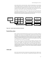
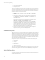
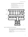
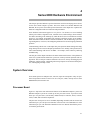
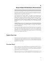
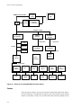
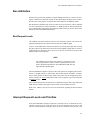
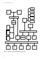
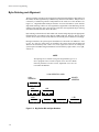
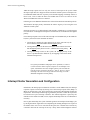
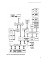
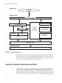
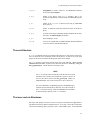
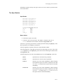
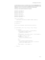
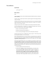
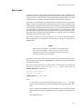
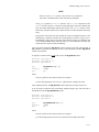
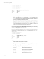
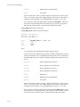
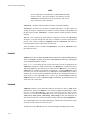
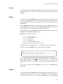
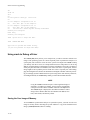
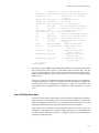
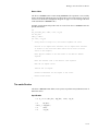
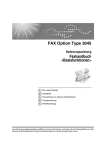
Figure 2-1 shows how a driver links the user level to the hardware level. By issuing system
calls from the user level, a program accesses the file and process control subsystems,
which access the device driver. The driver provides and manages a path to exchange data
with the device and receive service interrupts from the device's controller.
2-1
Device Driver Programming
User Level
System Call Interface
Kernel Level
Process Control
Subsystem
File Subsystem
I/O Subsystem Device Drivers
Hardware Control
Hardware Level
160970
Figure 2-1. Driver Placement in the Kernel
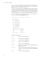
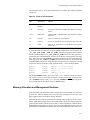
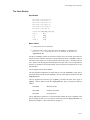
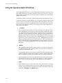
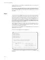
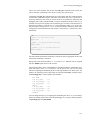
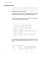
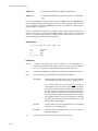
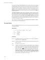
UNIX systems see every device as a file. Even the user-level interface to the device is
called a “special file.” The device special files reside in the /dev directory, and executing
a simple ls command reveals much about the device. For example, the command ls -l
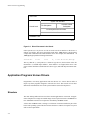
/dev/lp might yield the following information:
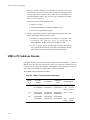
crw-rw-rw-
1 root
root
4,
0 Jul 26 12:45 /dev/lp
This says that the lp (line printer) is a character type device (the first letter of the file
mode field is c) and that major number 4, minor number 0 is assigned to the device. One
of the sections that follows further discusses device types, and both major and minor numbers.
Application Programs Versus Drivers
2
Programmers write many applications and most drivers in C. Device drivers differ in
major ways from programs designed to run at the user level. This section reviews those
differences and introduces some of the system facilities used to develop drivers.
Structure
2
The most striking difference between a driver and an application is in structure. An application compiles into a single executable image whose top-level structure is the main routine. Subordinate routines run in sequences controlled by the main routine.
A driver has no main routine, existing as a collection of routines installed as part of the
kernel. The operating system calls and executes the driver's routines in response to system
calls or other requirements.
2-2
Understanding Device Drivers
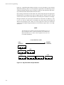
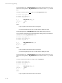
System data structures, called switch tables, contain the starting addresses for the principal
routines included in all drivers. Switch tables contain a row for each driver, and a column
for each standard routine. Standard routines are collectively named “entry-point routines”,
referring to the memory address where executions begins. The kernel translates the arguments of the system call into a value used as an index into the switch table.
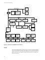
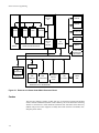
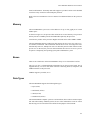
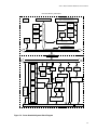
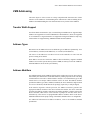
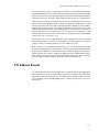
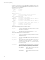
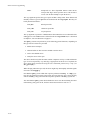
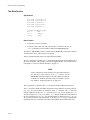
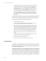
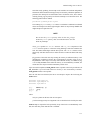
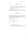
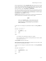
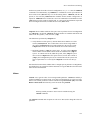
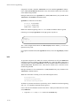
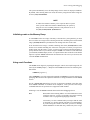
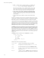
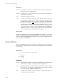
For example, a user process issues a system call to open a file. The kernel directs the
request to the switch table entry for the open routine of the device driver for the device
that contains the file (see Figure 2-2). The request executes the routine, either giving the
user process access to the file or returning an error code to the kernel.
User Issues
System Call To
Open Device
open
close
•••
A
open
close
•••
B
open
close
•••
C
Driver A
open Routine
Device A
Driver B
open Routine
Device B
Driver C
open Routine
Device C
160980
Figure 2-2. How the System Calls Driver Routines
Parallel Execution
2
When a traditional single-threaded application program runs, the statements making up
the program execute one at a time; in sequential order. Program control structures (loops
and branches) repeat statements and can branch to alternative sections of code, but at any
given instant only one statement and one routine executes. This is true even of different
instances of a program being run by two users at the same time (for example, a text editor).
As each process receives a scheduled slice of CPU time, the statements execute in the
order maintained for that invocation of the program.
Drivers, however, form part of the kernel and must run instantly at the request of many
processes. A driver might receive a request to write data to a disk while waiting for a previous request to complete. The design of the driver code must specifically enable it to
respond to numerous requests without creating a separate executable image of itself for
each request (unlike a text editor.) The driver does not create a new instance of itself (and
its data structures) for each process, so it must resolve contention problems resulting from
overlapping I/O requests.
Interrupts
2
Device drivers spend most of their execution time moving data between user address space
and a hardware device, such as a disk drive or terminal. Because hardware devices work
2-3
Device Driver Programming
much more slowly than the CPU, the data transfer can squander many processor cycles if
the CPU waits on the drive. To avoid this, the driver normally suspends execution of the
process until the transfer completes, freeing the CPU to service other processes. When the
data transfer completes, the device sends an interrupt telling the original process to resume
execution.
The processing needed to handle hardware interrupts is another of the major differences
between drivers and application programs.
Driver As Part of the Kernel
2
Applications, running at the user level, cannot severely impair the system. Performance
and efficiency considerations mostly affect them in their own address space. Applications
can use excessive disk space, but can neither raise their own priority level to use excessive
amounts of processing time nor access either sensitive areas of the kernel or other processes.
But drivers can and do affect the kernel. Inefficient driver code can severely degrade overall performance, and driver errors can corrupt or crash the system. For these reasons, testing and debugging driver code is particularly challenging, and requires great care.
Chapter 15 discusses both the tools for finding driver errors and the special problems in
testing driver code.
Also, while application programmers can freely (within reasonable limits) declare and use
data structures and system services, driver programmers face many constraints:
• Many kernel functions called by the driver do not validate passed arguments. Therefore, drivers must validate arguments before passing them to
kernel functions.
• Drivers must include numerous header files declaring data types, initializing constants, and defining system structures. The exact list of header files
varies from driver to driver; one of the following sections in this chapter
describes the most commonly-used header files.
• Drivers read from and write to various structure members and device registers, and often use a system buffering structure. The UNIX system Device
Driver Interface/Driver-Kernel Interface (DDI/DKI) defines many functions for use with drivers. Section D4 of the on-line Device Driver Reference explains the structures.
• Drivers cannot access standard C library routines; however, the routines
included in the DDI/DKI represent a kind of library and provide some
functions like those in the standard C library. The DDI/DKI also provides
many functions unlike standard C library functions. See Section D3 of the
on-line Device Driver Reference for complete explanations of the driver
interface routines.
2-4
Understanding Device Drivers
NOTE
Some of the DDI/DKI functions (such as kmem_alloc(D3))
resemble standard library functions (such as malloc(3C)), but
use different arguments. Serious errors result from ignoring such
differences.
• The kernel calls drivers using a set of system tables and the standard C
function-calling mechanism. Every member of these tables is a structure
containing pointers to the driver's entry point routines. The entry point routines connect the calling process to the device driver. The entry points, in
turn, call the driver functions to service the caller's requests. See Section
D2 of the on-line Device Driver Reference for complete explanations of the
driver entry point routines.
• Drivers cannot use floating point arithmetic.
Types of Devices
2
Interactive terminals and disk drives use different types of hardware device drivers, but
UNIX systems also support software devices, also called pseudo-devices, which differ yet
more.
Hardware Devices
2
Hardware devices include familiar peripherals such as disk drives, tape drives, printers,
and ASCII and graphics terminals. The list might also include optical scanners, analog-todigital converters, and robotic devices. In reality, a driver never talks to the actual piece of
hardware, but to its controller board. From the point of view of the driver, the device is
usually a controller. (The controller board, in turn, controls the actual hardware device.)
Sometimes a controller connects to a single device. More often, several devices connect to
a single board (such as eight terminals connected to a terminal controller). A single driver
controls that board and all similar terminal controllers in the system.
Software Devices
2
Software drivers control “devices” that usually consist of a portion of memory, sometimes
called a pseudo-device. As a possible use, the driver might provide applications access to
system structures otherwise unavailable at their level.
For example, a RAM disk is a software device which provides very fast access to files by
using a part of memory for mass storage. A RAM disk driver resembles a driver for a magnetic disk drive, but is free of the complications introduced by physical hardware.
2-5
Device Driver Programming
Types of Device Driver Interfaces
2
A device driver interface is the set of structures, routines, and optional functions used to
implement a device driver. UNIX systems provide three device driver interfaces, all based
on one specification, the Device Driver Interface/Driver Kernel Interface (DDI/DKI).
Block and Character Interfaces
2
Block and character are the two traditional UNIX system device driver interfaces, corresponding to the two basic ways drivers move data. Block drivers, using the system buffer
cache, service random-access devices such as disk drives and other mass storage devices
capable of handling data in independently addressable blocks. Character drivers service
devices that send and receive information one character at a time, such as interactive terminals.
It is the individual device and goal of the implementation, not the device type, that determines whether a driver should be the block or character type. For example, for a 9-track
tape drive one developer codes a block driver to mount file system images, even though
the drive performs random block accesses poorly. Another developer codes a character
driver to sequentially store and retrieve data.
A device can have more than one interface (only one interface at a time can access a
device.) The tape drive mentioned previously had both block and character interfaces. The
DDI/DKI sections of the on-line Device Driver Reference contain the manual pages for
the block and character interfaces.
STREAMS Interface
2
Early UNIX network drivers demonstrated a limitation of block and character interfaces;
they could not divide network protocols into layered modules. A new kind of interface,
STREAMS, has no such limitation.
A stream is a structure made of linked modules, each of which processes the transmitted
information and passes it to the next module. One of these queues of modules connects the
user process to the device, and another provides a data path from the device to the process.
This layered structure accommodates layered network protocols and increases the flexibility of the interface, making modules more usable by more than one driver.
For more information about STREAMS drivers, refer to STREAMS Modules and Drivers.
2-6
Understanding Device Drivers
Major and Minor Numbers
2
Before the operating system can access a device, the device needs its driver installed and a
special device file created for it in /dev. The special device file contains the major and
minor device numbers.
Major Numbers
2
The major number identifies the device class or group, such as a controller for several terminals. It tells the kernel which driver's open routine to call. Installable Driver Tools
(idtools) sequentially assigns major numbers to each device driver as it installs them. It
assigns the numbers by creating an entry in a driver system configuration file, the Master
file, described in a following section.
idtools assigns major numbers separately for block and character devices. This means
two separate special files for two different device drivers might have the same assigned
number. A device that supports both block and character access (for example, the floppy
driver), can have different major numbers for the character and block device files.
Minor Numbers
2
The minor number identifies a specific device, such as a particular terminal. Driver writers
assign minor numbers to special device files in another system configuration file, the
Node file (see the Node(4) manual page).
Minor numbers usually distinguish sub-devices, but can also convey other information.
For example, floppy disk controllers read and write data from floppies in several formats,
and manage two floppy drives. When the kernel opens the special file associated with the
floppy driver, the minor number used to open the file must tell the floppy driver both which
drive to access and what format to use for the I/O operation. In this case, the least significant bit of the minor number identifies the drive and the remaining bits identify the format.
Driver Entry Points and Kernel Utilities
2
This section discusses system tables and their associated entry points in detail.
Entry Points
2
Three ways exist to call a device driver:
• Initialization calls by boot routines
2-7
Device Driver Programming
• System calls by applications
• Interrupts by devices.
The process of initializing the system creates several tables so the system can activate the
correct driver routine. Because the system uses these tables to determine which driver routines to enter, common practice refers to the routines as driver entry points. Each table corresponds to a specific set of entry-point routines:
• Initialization tables correspond with either init(D2) or start(D2)
routines.
• System calls for character drivers use switch tables that correspond with
the open(D2), close(D2), read(D2), write(D2), and
ioctl(D2) routines.
System calls for block drivers use switch tables that correspond with the
open(D2), close(D2), and strategy(D2) routines.
System calls for STREAMS drivers indirectly access the open(D2),
close(D2), put(D2), and srv(D2) routines through a chain of
pointers to other structures. Since some of these reside in the driver, they
loosely resemble entry points. Therefore, the programming community
finds it both common and convenient to refer to them as such.
• Interrupt vector tables associate device interrupts with their interrupt handling routines; the entry point is the intr(D2) routine.
Initialization Entry Points
2
When the system starts, it executes both kinds of driver initialization routines (init and
start). It calls the routines and uses a subset of the information from the driver's configuration files to initialize the drivers. Much of the information is irrelevant to initializing
drivers, such as the major/minor numbers and driver type. (The system does not differentiate between character- and block-access drivers when running the initialization routines.)
Some drivers don’t need initialization routines.
During the boot sequence, the system initializes driver routines in the following order:
1. init routines
2. interrupts
3. start routines
4. other driver entry points.
The system calls the init and start routines of multiple drivers in no set order. If the
order needs setting, adjust the order field in the drivers’ Master(4) configuration file.
Switch Table Entry Points
2
I/O system calls activate switch table entry-point routines for character and block drivers
using the following procedure:
2-8
Understanding Device Drivers
1. The system directs the I/O system call (open and read, for example) to a special device file. This file includes the major number for
the driver that controls the device.
2. The system uses the major number as an index into its switch tables
to find the appropriate routine to call.
3. The operating system calls the appropriate routine. (Figure 2-3
depicts the between these components.)
System
Calls
open
close
read
write
mount
ioctl
un-mount
read
write
buffer cache
calls
File
Subsystem
Device Switch Table(s)
Driver
Entry
Points
open
close
read
write
open
ioctl
close
strategy
Driver
Character Driver
Block Driver
Interrupt Handler
Interrupt Vector
Device
160990
Figure 2-3. Switch Table Entry Points and System Calls
When the system does a character-access read or write operation on a device that
supports both block and character access, the driver typically calls its own strategy
routine (through physiock(D3)). The driver references its strategy routine directly,
not through a switch table.
STREAMS drivers contain their own entry points accessed indirectly through the driver's
streamtab(D4) structure.
2-9
Device Driver Programming
Devices need not use all the entry points provided by the switch table. For instance, printer
drivers do not need read routines. The operating system provides place holders in the
switch tables for unneeded routines.
Interrupt Entry Points
2
The operating system must handle many kinds of system interrupts (such as clock and
software interrupts), system exceptions (such as page faults), and interrupts from peripheral devices controlled by drivers. Interrupts cause the processor to stop its current process
and to immediately begin to service the interrupt. Peripheral devices typically generate
interrupts when an I/O transfer encounters an error or completes successfully.
When it receives an interrupt from a hardware device, the kernel determines the interrupt
vector number of the device and passes control to the appropriate driver's interrupt handling routines. It does this by accessing the interrupt vector table, populated during system
initialization. The interrupt handler must determine the reason for the interrupt (device
connect, write acknowledge, data available) and set or clear device state bits as appropriate. It can also awaken processes that sleep while awaiting an event corresponding to the
interrupt.
Kernel Support Routines
2
UNIX system device drivers call kernel support routines to do system-level work such as:
accessing memory
adjusting processor levels
allocating interrupt vectors
allocating memory
debugging
managing virtual address
synchronizing
timing and timeout
transferring data
Chapter 9 (“Understanding the Kernel Environment”) describes these routines and their
use in device drivers. Section D3 of the on-line Device Driver Reference contains manual
pages for all of these routines.
Driver Environment
2
Installation and Configuration
2
To integrate a driver into the system requires adding information to the system configuration files about it, such as type, location of object code, and interrupt priority level.
Four phases comprise the process of adding a device driver to a working system:
2-10
Understanding Device Drivers
1. Prepare a Driver Software Package (DSP), including the Driver.o object
module (the actual driver code), Master, System, and if needed
Sadapters file definitions, and other components.
2. Install the driver's DSP
3. Update the system configuration files
4. Prepare to generate a new kernel.
5. Shutdown and reboot the system. During the reboot, the system uses information from the modified system configuration files to create special files
in /dev, and the entries for the new driver in the system initialization
tables, switch tables, and interrupt vector tables. When the system reinitializes, it initializes the driver as part of the kernel.
NOTE
Loadable drivers integrate into the kernel while the system runs,
without rebooting the system and rebuilding the kernel.
Chapter 13 (“Loadable Modules”) describes how to install and
configure loadable drivers.
The Installable Driver Tools (idtools) utilities install and configure drivers. Chapter 14
(“Driver Installation and Tuning”) details installing and configuring drivers, and how the
system initializes.
Master, System, and Sadapters Files
2
The following files contain important configuration information needed to integrate a
driver into a running system:
• Master
• System
• Sadapters (for adapter card drivers)
Master File
2
The Master file describes properties of the driver as a whole, regardless of the number of
devices supported. Once installed, the driver’s Master file resides in the directory
/etc/conf/mdevice.d. This directory contains a separate Master file for each
device driver installed. Once installed, Driver Software Packages (DSPs) should never
access these or any other idtools files directly; use idtools commands to access them.
Configuration data defined in the Master file includes the names of the driver's entry
point routines, and an alphanumeric prefix (assigned by the driver writer) prepended to the
names of the driver's routines in the system tables. The prefix enables the kernel to distinguish between drivers’ routine names (and other variables), avoiding conflict with other
variables in the system named alike. For example, a RAM disk driver given a prefix of
2-11
Device Driver Programming
ram_ results in routines named ram_open, ram_init and so on. For more information, see the prefix(D1) manual page.
The Master file can also contain the driver's major number and various flags defining
specific characteristics of that driver (for example, whether a character or block driver).
During installation, the idtools assign a major number if the driver's Master file doesn't
specify one. For more information, see the Master(4) manual page.
System File
2
A driver's System file provides information needed to configure the driver into the next
kernel build. After installation, the driver’s System file resides in the directory
/etc/conf/sdevice.d. This directory contains a separate System file for each
device driver installed.
Configuration data defined in the System file includes a flag that indicates whether or not
the driver ought to be incorporated into the kernel. For more information, see the
System(4) manual page.
Sadapters File
2
A driver's Sadapters file identifies and describes the functional characteristics of an
adapter card so the system can incorporate it into the next configuration built. The Master and System files describe the adapter with general configuration information. When
the kernel module’s Driver Software Package is installed, idinstall(1M) stores the
Sadapters file information in $OBJ/etc/conf/sadapters.d/kernel.
Driver Header Files
2
Driver source code must contain some standard #include files giving the driver access
to system utilities and data structures used to return information to the kernel.
The description of each kernel utility function in the DDI/DKI manual pages indicates
which header files must be included in a driver that uses that function. Chapter 9 (“Understanding the Kernel Environment”) describes the standard header files typically included
in a device driver’s source file.
Driver Development
2
Device driver development requires more up-front planning than most application programming projects. At the very least it involves more testing and debugging, and requires
more hardware knowledge. Chapter 10 (“Developing a Device Driver”) explains the full
procedure for developing device drivers. Chapter 14 (“Driver Installation and Tuning”)
describes procedures for installing device drivers. Chapter 15 (“Driver Testing and Debugging”) describes the tools available for testing and debugging installed device drivers.
2-12
3
The PCI Environment
Introduction . . . . . . . . . . . . . . . . . . . . . . . . . . . . . . . . . . . . . . . . . . . . . . . . . . . . . . . .
PCI Variants and Form Factors . . . . . . . . . . . . . . . . . . . . . . . . . . . . . . . . . . . . . . . . .
Big Vs Little Endian Issues . . . . . . . . . . . . . . . . . . . . . . . . . . . . . . . . . . . . . . . . . . . .
RISC Vs CISC CPU Processor Issues . . . . . . . . . . . . . . . . . . . . . . . . . . . . . . . . . . . .
Types of PCI Resources. . . . . . . . . . . . . . . . . . . . . . . . . . . . . . . . . . . . . . . . . . . . . . .
Configuration Space . . . . . . . . . . . . . . . . . . . . . . . . . . . . . . . . . . . . . . . . . . . . . .
Base Address Registers(BAR) . . . . . . . . . . . . . . . . . . . . . . . . . . . . . . . . . . . . . .
Decode into I/O Space. . . . . . . . . . . . . . . . . . . . . . . . . . . . . . . . . . . . . . . . .
Decode into Memory Space . . . . . . . . . . . . . . . . . . . . . . . . . . . . . . . . . . . .
ROM Base Address Registers(BAR) . . . . . . . . . . . . . . . . . . . . . . . . . . . . . . . . .
Decode into Memory Space . . . . . . . . . . . . . . . . . . . . . . . . . . . . . . . . . . . .
Interrupts . . . . . . . . . . . . . . . . . . . . . . . . . . . . . . . . . . . . . . . . . . . . . . . . . . .
System Memory and PCI bus Master Devices . . . . . . . . . . . . . . . . . . . . . .
Effects of PCI to PCI Bridges. . . . . . . . . . . . . . . . . . . . . . . . . . . . . . . . . . . . . . .
PowerMax OS Support . . . . . . . . . . . . . . . . . . . . . . . . . . . . . . . . . . . . . . . . . . . . . . .
Finding the Correct Adapter Structure . . . . . . . . . . . . . . . . . . . . . . . . . . . . . . . .
Accessing the Configuration Space Registers . . . . . . . . . . . . . . . . . . . . . . . . . .
Getting/Releasing the Base Address Register Assignments. . . . . . . . . . . . . . . .
Determining the Kernel Virtual Address of PCI Base Address Register . . . . . .
Accessing PCI Device Registers and Memory Space
Though Kernel Virtual Maps . . . . . . . . . . . . . . . . . . . . . . . . . . . . . . . . . . . . . . .
Determining PCI Memory Address of Particular System Memory
Location . . . . . . . . . . . . . . . . . . . . . . . . . . . . . . . . . . . . . . . . . . . . . . . . . . . . . . .
Attaching and Releasing a PCI Interrupt Vector Assigned to a
PCI Slot/Function . . . . . . . . . . . . . . . . . . . . . . . . . . . . . . . . . . . . . . . . . . . . . . . .
3-1
3-1
3-2
3-3
3-3
3-3
3-4
3-4
3-4
3-5
3-5
3-5
3-5
3-5
3-5
3-6
3-6
3-6
3-6
3-7
3-7
3-7
Device Driver Programming
3
Chapter 3The PCI Environment
3
3
3
Introduction
3
The PCI (Peripheral Component Interconnect) BUS specifications was created out of the
need to create a simple plug and play mechanism for access I/O resources. PCI has several physical and electrical variances. Generally, a PCI based system can have up to 256
PCI buses with upwards of ten(10) PCI devices per bus. Practically, the actual number of
PCI buses and devices is generally restricted by other factors.
The following sections will cover varies aspects of the PCI environment as supported by
PowerMax running under Motorola base platforms. A subset of functionality described in
this chapter is supported by PowerMax on NightHawk Platforms. The supported PCI
subset varies by combinations of NightHawk platforms and their respective PowerMax
OS releases, contact Concurrent Corporation for support when attempting to use PCI
devices on these platforms.
PCI Variants and Form Factors
3
The variants of PCI buses are PCI 32/64 bit, PMC(PCI mezzanine connector)(32/64bit),
and CompactPCI (32/64bit) with either 5.0volt or 3.3volt drivers and running at either
33mhz, or 66mhz bus speeds. Also, the Advance Graphics Port(AGP) specification is a
variant of PCI 64bit/64mhz with special 133/266mhz modes with either 1.5volt or 3.3volt
drivers. Each PCI variant has a unique connector configuration with some implementations able to support boards that require only a subset of that function.
Generally the 64 bit PCI variants can accommodate 32 bit cards with some restrictions.
The faster PCI bus speeds reduced the number of available slots for add in PCI devices.
Wider PCI buses usually have extra connectors installed to supply connectivity for the
additional signals. PCI buses which support 5.0 volt drivers are keyed differently from
those that which support only 3.3 volt or 1.5 volt bus drivers.
The most common PCI form factors are:
-
PCI 32 bit, running between 25 and 33mhz with 5.0volt drivers
PMC 32 bit, running between 25 and 33mhz with 5.0volt drivers
Compact PCI 32/64 bit, running at 33mhz with 5.0volt drivers
There are also 64 bit implementations of PCI, PMC and AGP buses. These
3-1
Device Driver Programming
high performance form factors are used only when the design of the add on device requires
performance or resources that exceed that available in the commonly available form factors. These high performance buses must be directly connected or bridged into by other
equally high performance PCI buses to System memory, to do otherwise the would compromise the performance gain available.
Logically, a single PCI bus can have thirty-two(32) device slots with up to eight(8) functions per device slot. Additional PCI busses can be supported by adding PCI to PCI bridge
chips to connect additional PCI buses to a system.
Electrical considerations reduce the thirty two (32) logical slots down to ten(10), or less
physical PCI devices based on the type of PCI bus extended and connector type.
There are some PCI extender configurations that allow a PMC form factor system to connect standard PCI 32/33mhz(5volt) boards.
Generally, the PCI bus support is limited by the platform’s hardware design thus most
restrictions and subsequent PCI support are determined on a platform by platform basis.
The different types of PCI bus form factors, clock speed, bus width, and voltage of bus
drivers are normally transparent to the programming interface.
Big Vs Little Endian Issues
3
Endian issues occur whenever mathematical operations manipulate a data item whose
width is greater than a byte(8 bits) and the CPU architecture is addressable to a byte based
address. For the most part, byte oriented strings of information are stored in the same
manor whether the architecture is big or little endian.
When the data width of the object exceeds that of a byte is when the endianess of the
architecture becomes significant. A little endian architecture stores the least significant
byte (LSB) in the lowest addressable byte, while a big endian architecture stores the most
significant byte (MSB) in the lowest addressable byte.
• The PCI bus is little endian by design.
• The VME bus is big endian by design.
• Most real world protocols are big endian. (TCP/IP, NFS, SCSI)
• Intel platforms using x86 processors are little endian.
• The PowerPC processor is capable of manipulating either big or little
endian data items, but must be defaulted to one or other on a per application or OS basis.
PowerMax is defaulted to manipulate big endian data items.
An address invariant translation generally occurs when reading or writing data objects so
that the appropriate byte lane(s) are used when transferring blocks of data, thus character
or byte oriented strings are stored in the correct order. Address invariant translation can
occur several (up to 3) times depending on the number of big and little endian conversions
required as a I/O cycle traverses between it’s source and destination.
3-2
The PCI Environment
Endian translation is necessary whenever a memory or I/O mapped address space is
accessed, or when accessing configuration space in data widths less than 32 bits.
To provide a common mechanism of byte swapping, the BUSGETSR, BUSGETLR, BUSPUTSR and BUSPUTLR macros are provided in the xxxx.h header file.
RISC Vs CISC CPU Processor Issues
3
Generally RISC processors behave in a similar fashion to CISC processors except in two
areas.
RISC processors generally require that a data item must be addressed on a native
address boundary. For example, a 4 byte access must occur on an address boundary that is
evenly divisible by 4.
The second difference is instruction reordering, this aspect of RISC processors is a feature
of the large number of general purpose registers in the design When a particular register
is still busy being manipulated by a instruction a subsequent instruction can proceed as
long as it deals with a non-busy register. This can cause I/O or memory accesses to be
executed out of order with respect to the designers intent.
To overcome endian and reordering issues the designer should use the byte swapping and
i/o flushing macros described previously in the Big verses little endian section.
Types of PCI Resources
3
Configuration Space
3
The PCI configuration space is a mechanism by which the PCI bus configures virtually all
other characteristics of the devices installed. It allows the Plug and Play nature of PCI bus
to become a reality. Allowing a system to dynamically assign system resources to the
devices that are installed or plugged into a PCI bus somewhere on the system. PCI devices
can be arranged in a virtually unlimited number of configurations, where some devices are
directly installed in the system while others are located in PCI expansion busses behind
PCI to PCI bridges. Each PCI to PCI bridge has been configured by PowerMax at IPL
time to forward all necessary I/O, memory, interrupts, and configuration accesses for the
PCI devices it bridges automatically. Care must be taken not to override the system settings of PCI devices using mechanisms not provided. To do otherwise would cause conflicts with other PCI devices in an unpredictable manor.
The PCI configuration space is broken up into 256 Buses with 32 slots, and 8 functions per
slot. Each function has up to 256 bytes of configuration information. Some devices can
forgo the use of the additional functions and utilize the entire 2048 byte range assigned to
each PCI slot. The PCI specification only defines the first 64 bytes of each slot or function
3-3
Device Driver Programming
of the configuration space. The remaining 192 or 1984(2048-64) is reserved for custom
use by the device.
Within the configuration space of a PCI device/function 28 of the 64 bytes are reserved for
Base address registers(BAR’s). These are read/write registers that are used to set the starting I/O and Memory space address for any additional resources required by the device.
The type and the size of the resource is determined by the read-only portion of each Base
Address register(BAR). PowerMax scan’s all devices connected to the PCI bus when the
system is booted. When PowerMax scans a PCI device it queries the BAR to determine
the resources required. If PowerMax can satisfy the requirements the OS reserves the necessary resources and writes the appropriate base address value into BAR.
The configuration space of PCI is generally accessed via a special hardware mechanism
and does not generally appear as a directly accessible memory region. A device’s configuration space is accessed via a Type 0 configuration cycle while devices connected via PCI
bridges are accessed using Type 1 configuration cycles. When a Type 1 cycle reaches it’s
final destination PCI bus it is converted to a Type 0 configuration cycle. Thus a normal
PCI device must only need to respond to Type 0 configuration cycles without regard to it’s
actual placement within the PCI architecture.
Base Address Registers(BAR)
3
Decode into I/O Space
3
The PowerPC architecture does not allow for a separate I/O space as is allowed in the x86
family which the PCI bus was originally designed for. Thus to access those I/O mapped
resources made available by various PCI devices a region of PowerPC memory space is
dedicated to mapping memory accesses into PCI I/O accesses.
The I/O access region is automatically allocated by the PowerMax OS and requisite reservations are provided for to allow all I/O Base Address Registers of each device to be
accessed by the driver.
The I/O access region is normally allocated in virtual memory page multiples to remove
the possibility of driver or device conflicts.
As with all non-memory cycles the PowerPC cache is inhibited, but the write posting pipeline is not. To inhibit the possible effect of the write reordering the user must use the
appropriate PowerPC flush instructions after writing each I/O location.
The flush instructions described above are included within the byte swapping macro’s provided.
Decode into Memory Space
3
The memory region is a cache inhibited area where the appropriate Base Address Registers are assigned to. This area has many of the same characteristics of the I/O space
described previously. These characteristics include page alignment, and the same need for
pipeline flushing on writes.
3-4
The PCI Environment
ROM Base Address Registers(BAR)
3
Decode into Memory Space
3
Similar to Base Address Registers that decode into Memory Space with the same characteristics. These areas are allocated out of the space set aside for PCI memory space.
Interrupts
3
Each sub function of a PCI device can request one interrupt to be attached to the specified
Interrupt Pin defined at offset 0x3d. It should be noted that it is highly unlikely that the
Interrupt vector assigned will be exclusive to this device only. Thus all device drivers
must be written with the intent that the vector is shared and it’s respective interrupt handler
will be called at random times with no activity to process.
System Memory and PCI bus Master Devices
3
The entire memory subsystem of PowerPC which can be as large as 2 gigabytes which is
statically mapped into the memory space portion of the PCI bus. This allows the PCI bus
master devices to access the system memory without further intervention by the CPU.
Effects of PCI to PCI Bridges
3
The effects of PCI to PCI bridges on PCI devices it bridges can vary, but generally they
slow down individual read accesses the most. Most PCI bridges have write posting buffers
that allow a couple of writes to be queued in each layer of PCI bus, thus improving the
performance of individual writes to/from PCI devices. These queues are generally flushed
when a read occurs thought the same data path. The effects of PCI bridges on a PCI bus
master is less pronounced since they generally move more data per PCI arbitration timing
slot. Where most of overhead by PCI bridges is in the setup and the first access. To reduce
this effect even further the programmer should maximize the Bus mastering burst size to
the largest the device can accommodate within reason. This value is generally of the total
DMA FIFO size.
PowerMax OS Support
3
Each PCI device and sub function are assigned a adapter structure entry at System IPL
time. Normally the sub functions of each PCI device should be treated as separate
devices. I.E. SCSI and Ethernet functions combined on a single chip. However their are
exceptions and a single driver may manipulate multiple functions, for that case it should
be noted that all the sub functions will be clustered together in a serial fashion in the
adapter array.
3-5
Device Driver Programming
Finding the Correct Adapter Structure
3
Use the routines adapter_find and adapter_find2 to locate instances of your device. An
alternate method is to scan the external “adapters” array for “adapter_count” entries and
match the “adapter_type” element with a value generated from the macro
“ P C I _ A DA P T E R _ T Y P E ” a n d c h e c k t h e “ a d a p t e r _ s t a t e ” e l e m e n t f o r t h e
“ADAPTER_PRESENT” flag.
Accessing the Configuration Space Registers
3
Use the routines “pci_cfgspc_read” and “pci_cfgspc_write” to access the configuration
space registers other than a BAR or the “PCI CMD” register. A prerequisite for correct
operation is that the routines must be given a pointer to the correct “adapter” structure
entry. Note: These routines read and write 32 bit quantities on 4 byte aligned boundaries
only.
Use “pci_cfg_cmd” routine to enable/disable PCI I/O and memory space slave operation.
This routine has no effect on Configuration space accesses. The “pci_cfg_cmd” routine is
also used to enable PCI bus master operation.
As a general note, most PCI devices also have a Base Address Register assigned to map
the PCI device’s configuration registers. It would advisable to use the BAR mapped configuration space registers to access these resource whenever they required frequent accessing by the device driver during normal operation.
Getting/Releasing the Base Address Register Assignments
3
Use the “pci_iospc_alloc”, “pci_memspc_alloc”, “pci_iospc_free” and
“pci_memspc_free” routines to retrieve assigned values from Base Address Registers or
release them. The “iospc” and “memspc” versions may be used interchangeably, as they
will retrieve the assigned values or query the PCI device to determine which type of PCI
space is required.
The returned “pci_spc_t” structure will contain the type of space, size, the assigned PCI
address and the equivalent CPU physical address.
It is not necessary or desirable to release PCI allocations each time the driver is closed or
unloaded. The allocation routines will return the same values for each BAR every time
they are called. The exception to this rule is if you release them using a
“pci_XXXspc_free” call. In which case the assigned address may be different or fail allocate.
Determining the Kernel Virtual Address of PCI Base Address Register3
To get a working Kernel virtual address of a PCI Base address register, the “physmap”
3-6
The PCI Environment
call must be used. The arguments must include the CPU physical address and the size of
the PCI BAR register returned from the “pci_XXXspc_alloc” call.
Use the “physmap_free” call to release the Kernel virtual address assignment associated
with a PCI BAR assignment.
Accessing PCI Device Registers and Memory Space
Though Kernel Virtual Maps
3
It is important to remember to use the byte swapping and pipeline flushing Macros provided when accessing PCI devices directly. These macros BUS_GETLR, BUS_GETSR,
BUS_GETBR and BUS_PUTLR, BUS_PUTSR, BUS_PUTBR include the necessary
byte swapping and FIFO flushing instructions to manipulate little endian PCI devices
using a PowerMax which is defaulted to big endian mode.
Determining PCI Memory Address of Particular System Memory
Location
3
To get a valid PCI memory address equivalent to a particular system memory location one
should use the “pci_vtop” call. This returns a PCI memory address that can be used by a
PCI bus master device.
The ‘pci_vtop” call does not lock down or establish any resource that requires releasing.
Therefore, the programmer must insure that each virtual page is locked down and nonswapable.
Attaching and Releasing a PCI Interrupt Vector Assigned to a
PCI Slot/Function
3
The “adapter” structure entry for a PCI device/slot/function already contains the necessary
information about the Interrupt assignment. It is only necessary to register a handler entry
point or release the handler entry point from within the device driver.
The call to attach or release the interrupt handler entry point is “ivec_init” and “ivec_free”.
Both of these calls should use the “ivec” member of the “adapter” structure as the first
argument.
A special note, the PCI device must be fully initialized or have a disable mechanism established to anticipate that handler attached, could be entered at any time, including immediately after being attached. This occurs because PCI interrupts are shared in nature and the
entry could be for another PCI device which shares the same vector.
3-7
Device Driver Programming
3-8
3
Series 6000 Hardware Environment
System Overview . . . . . . . . . . . . . . . . . . . . . . . . . . . . . . . . . . . . . . . . . . . . . . . . . . . .
Processor Board . . . . . . . . . . . . . . . . . . . . . . . . . . . . . . . . . . . . . . . . . . . . . . . . .
Caches . . . . . . . . . . . . . . . . . . . . . . . . . . . . . . . . . . . . . . . . . . . . . . . . . . . . .
Memory . . . . . . . . . . . . . . . . . . . . . . . . . . . . . . . . . . . . . . . . . . . . . . . . . . . . . . .
Buses. . . . . . . . . . . . . . . . . . . . . . . . . . . . . . . . . . . . . . . . . . . . . . . . . . . . . . . . . .
Data Types . . . . . . . . . . . . . . . . . . . . . . . . . . . . . . . . . . . . . . . . . . . . . . . . . . . . .
Byte-Ordering and Alignment . . . . . . . . . . . . . . . . . . . . . . . . . . . . . . . . . . . . . .
(H)VME Addressing . . . . . . . . . . . . . . . . . . . . . . . . . . . . . . . . . . . . . . . . . . . . . . . . .
Transfer Width Support . . . . . . . . . . . . . . . . . . . . . . . . . . . . . . . . . . . . . . . . . . .
Address Types. . . . . . . . . . . . . . . . . . . . . . . . . . . . . . . . . . . . . . . . . . . . . . . . . . .
Address Modifiers . . . . . . . . . . . . . . . . . . . . . . . . . . . . . . . . . . . . . . . . . . . . . . .
HVME Address Ranges . . . . . . . . . . . . . . . . . . . . . . . . . . . . . . . . . . . . . . . . . . .
VME Address Ranges . . . . . . . . . . . . . . . . . . . . . . . . . . . . . . . . . . . . . . . . . . . .
(H)VME Devices as (H)VME Bus Slaves . . . . . . . . . . . . . . . . . . . . . . . . .
(H)VME Devices as Bus Masters . . . . . . . . . . . . . . . . . . . . . . . . . . . . . . . .
Bus Time-Out . . . . . . . . . . . . . . . . . . . . . . . . . . . . . . . . . . . . . . . . . . . . . . . . . . .
VME Device Address Assignment and Configuration. . . . . . . . . . . . . . . . . . . .
Bus Arbitration . . . . . . . . . . . . . . . . . . . . . . . . . . . . . . . . . . . . . . . . . . . . . . . . . . . . .
Bus Request Levels . . . . . . . . . . . . . . . . . . . . . . . . . . . . . . . . . . . . . . . . . . . . . .
Configuring Devices Without BR0 . . . . . . . . . . . . . . . . . . . . . . . . . . . . . . .
Interrupt Request Levels and Priorities . . . . . . . . . . . . . . . . . . . . . . . . . . . . . . . . . . .
Interrupt Lines (Levels) . . . . . . . . . . . . . . . . . . . . . . . . . . . . . . . . . . . . . . . . . . .
Interrupt Vector Generation and Configuration . . . . . . . . . . . . . . . . . . . . . . . . . . . . .
3-1
3-1
3-2
3-3
3-3
3-3
3-4
3-4
3-5
3-5
3-5
3-6
3-6
3-6
3-6
3-8
3-8
3-9
3-9
3-10
3-11
3-11
3-12
Device Driver Programming
4
Chapter 4Series 6000 Hardware Environment
4
4
4
This chapter provides hardware-specific information useful in developing device drivers
for the Series 6000 computer systems. The Series 6000 covers models HN6200 and
HN6800; the text points out model-specific information. This chapter also explains how
hardware configuration affects I/O function and performance.
Some hardware information applies to every driver—for instance, I/O error handling
(affects power failure, alignment errors, controller errors, and bus hangs.) Some information differs according to the technique by which the device driver communicates with the
processor—for example, programmed I/O, interrupts, and direct memory access (DMA).
Other information relates as much to software as hardware, such as addressing, byte ordering and alignment, word sizes, and configuring arbitration levels and assigning arbitration
priorities.
Communicating with devices via interrupts also poses questions about sharing and configuring interrupt levels to ensure adequate performance levels. Finally, other questions arise
when communicating with devices via DMA—for example, cache coherency, buffering
and addressing.
The first part of this chapter introduces the main architectural features of the platform in
terms of its system and I/O architecture: processors, memory and I/O expansion and configuration. The second part examines hardware issues more closely including physical
addressing, I/O bus timeout, configuring I/O interrupt request levels and associated priorities, and assigning interrupt vectors.
System Overview
4
Series 6000 systems are multiprocessor, real-time, super-microcomputers. They use Symmetric SuperscalarTM Reduced Instruction Set Computer (RISC) microprocessors from
IBM/Motorola, the PowerPC 604.
Processor Board
4
Figure 4-1 depicts the main architectural features of the HN6800 computer system. The
HN6800 computer system can contain up to four processor boards. A processor board
hosts up to two processors, local memory module board, I/O interface, timers, real-time
clocks, UART, and associated components.
The processor clock speed is 150 or 200 MHz (depending on model) and can execute four
instructions per cycle. The processor data bus is 64-bits wide to accommodate two 32-bit
instructions per cycle. The HN6200 or HN6800 Architecture Manual describes the processor board in greater detail.
4-1
Device Driver Programming
Processor Bus
Local Bus
Control
PowerPC
604
Local Memory
50MHz Static
or
50MHz Dynamic
PowerPC
604
Local Bus
Port Interface
Bus Watcher
(Snoop Filter)
Frontplane
Interface
HVME Interface
ISE
Global
Memory
Disc
Tape
System
Frontplane
HVME Backplane
CIO
Secondary
Interface
I/O
Local Bus
Error
Add Reg
TOC
RTC
EPROM
Diagnostic
Control
UART
Interval
Timer
CPU
ID
Register
Error
ID
Register
Health
Register
Interrupt
Controller
Figure 4-1. Elements of an HN6800 Processor Board
Caches
4
The processor features separate 16-Kb, four-way set-associative instruction and data
caches. Software maintains instruction cache coherency; bits in the instruction cache flag
whether a cache block is valid. Hardware maintains four-state data cache coherency
(MESI). The processor also supports secondary data cache. Software can disable, lock,
and parity-check caches.
4-2
Series 6000 Hardware Environment
Memory
4
The HN6800 system uses 32-bit addresses for up to four gigabytes of virtual address
space.
Figure 4-1 shows that any processor on the processor board has cached access to local
memory. The local memory resides on a daughter card attached to the processor board.
The daughter card provides up to 128 MB of dynamic or 64 MB of static memory.
The local memory burst rate of 50MHz matches without saturation the bandwidth
demands of both local processors accessing memory concurrently.
The HN6800 memory architecture also supports an Error Detection and Correction
(EDAC) mechanism. This mechanism automatically detects and corrects single-bit errors.
The EDAC mechanism detects multiple-bit errors only upon the first read access to a corrupted memory location, but cannot correct them. (The system cannot recover from multiple-bit errors.) The EDAC reacts by raising a precise hardware exception to the processor
initiating the access, which panics the operating system and halts it.
Buses
4
The Series 6000 has two main buses: the processor bus and the local bus.
The processor bus, a dedicated high-performance bus resides on the processor board connecting to the main bus, a local bus. The local bus connects the CIO, port, frontplane
(HN6800 only), and HVME interfaces to the processors.
HVME extends the VMEbus standard. The most important extensions are parity error
reporting and fast synchronous burst mode. Fast synchronous burst mode transfers data at
rates up to 40 MB/sec, depending upon system configuration. The HVME bus extension
also provides other hardware-specific improvements not affecting device programming.
Specific improvements include a larger board size with more power supply pins on the I/O
connectors and eliminating daisy-chained backplane jumpers. Refer to the HVME Extension Specification for details. Note that any VME board works on the HVME bus.
Data Types
4
The Series 6000 supports the following data types:
• Byte (8 bits)
• Half-Word (16 bits)
• Word (32 bits)
• Doubleword (64 bits)
The Series 6000 computer system is a 64-bit machine, but this manual uses the term word
for sixteen bits and longword for 32 bits to remain compatible with other industry standard
systems.
4-3
Device Driver Programming
Byte-Ordering and Alignment
4
The Series 6000 platform orders bytes according to the Big Endian convention, in which
the most significant byte (MSB) always has the lowest address. This provides consistent
addressing independent of the machine word size, as Figure 4-2 depicts. (Note that the bit
ordering depicted (with bit 31 most significant) applies to I/O addressing. The bit ordering
of the PowerPC 604 is the opposite (with bit 0 most significant). Byte ordering for both
I/O and the PowerPC 604 is the same.)
During I/O transfers, the system expects the addresses of all words to be even addresses—
that is, zero, two, four, six, eight, and so on. Similarly, the system expects that all longword addresses are divisible by four—that is zero, four, eight, twelve, and so on. Finally,
the system expects all double-longword addresses to be divisible by eight—that is, zero,
eight, sixteen, and so on.
NOTE
Starting an I/O transfer using non-aligned data types in a driver
program causes a fatal exception error on all Series 6000 platforms. In other words, the hardware cannot recover from alignment errors.
LOW ADDRESS = MSB
LOW
ADDRESS
HIGHER
ADDRESS
0
7
MSB
15
LSB
8
7
0
LSB
MSB
31
24
23
16
15
8
7
0
Figure 4-2. Big Endian Bit and Byte Notation
(H)VME Addressing
4
This section describes the characteristics of data transfers on the (H)VME bus. Doing so
aids in building device addresses and understanding the error detection and recovery feature of the VMEbus.
4-4
Series 6000 Hardware Environment
Transfer Width Support
4
For all non-block mode transfers, (H)VME supports byte, word and long-word addresses.
It supports byte addresses on even and odd addresses. It supports word addresses (16-bit)
on even addresses. It supports longword transfers on longword addresses.
Synchronous Block Transfers or VME Block Mode Transfers (BMT) only support longword addresses.
Address Types
4
Bus masters on the (H)VME I/O bus can use different types of addresses dynamically:
short (16 bit-address), standard (24-bit addresses), or extended (32-bit addresses).
The source of the addresses can either reside on the local (H)VME bus or come from the
processor acting as bus master.
Short address accesses come from sources local to the (H)VME I/O bus on which they
originate, and cannot go outside of the local bus. Standard addresses can access either system memory (below 12MB) or memory local to the (H)VME bus. Extended addresses
access all of system memory.
Address Modifiers
4
For each data transfer on the (H)VME bus, the bus master (either a processor or an I/O
device) must identify the characteristics of the data transfer by sending a special six-bit
code along with the transfer. This code is called an address modifier. Different types of
data transfers use specific address modifier values. The address modifier specifies:
• Address type (short, standard, extended)
• Access method (single location or multiple locations)
• Data access privilege (supervisory or non-privileged).
If the transfer originates with the processor, the (H)VME I/O interface generates the
appropriate address modifier. If the device initiates the transfer, the device controller generates the address modifier. In some devices, the address modifier is hard-wired into the
device controller; in others, jumpers or switches on the device set it. Alternatively, some
devices have programmable address modifiers. Refer to the installation manual that
accompanies the device for the procedure to configure the address modifier.
The HN6200 or HN6800 Architecture Manuals contain additional information on address
modifiers.
4-5
Device Driver Programming
HVME Address Ranges
4
Table 4-1 shows the address ranges for HVME devices:
Table 4-1. HVME Address Range
Address Type
HVME Primary
A32
0xC00000000xD5FFFFFF
VME Address Ranges
4
This section details the address ranges VME devices use on the (H)VME primary I/O bus
as bus masters or slaves.
(H)VME Devices as (H)VME Bus Slaves
4
When a processor acts as bus master on the (H)VME bus and addresses (H)VME devices
on the (H)VME I/O bus, the (H)VME devices are slave devices.
Table 4-2 shows the address ranges for HVME slave accesses:
Table 4-2. HVME Bus Slave Access
Address
Type
Address Modifier
Address Range
A32
0x09
0xC00000000xFEFFFFFF
A24
0x39
0xFF0000000xFFFEFFFF
A16
0x2D
0xFFFF00000xFFFFFFFF
(H)VME Devices as Bus Masters
4
When an (H)VME device addresses memory (or other (H)VME sources), the (H)VME
device is the bus master.
4-6
Series 6000 Hardware Environment
Table 4-3 shows the address ranges for (H)VME bus master accesses:
Table 4-3. HVME Bus Master Access
Transfer Type
Address Range
Address Type
Address Modifier
single
00000000-0FFFFFFF
A32
09, 0A, 0D, 0E
block
00000000-0FFFFFFF
A32
0B, 0F
block
00000000-0FFFFFFF
A32
08,0F
sync block
00000000-0FFFFFFF
A32
1A, 1B, 1C, 1D
single,
slot 1
40000000-4FFFFFFF
A32
09, 0A, 0D, 0E
block
slot 1
40000000-4FFFFFFF
A32
0B, 0F, 08, 0C
sync block
slot 1
40000000-4FFFFFFF
A32
1A, 1B, 1C, 1D
single
slot 2
50000000-5FFFFFFF
A32
09, 0A, 0D, 0E
block
slot 2
50000000-5FFFFFFF
A32
0B, 0F, 08, 0C
sync block
slot 2
50000000-5FFFFFFF
A32
1A, 1B, 1C, 1D
single
slot 3
60000000-6FFFFFFF
A32
09, 0A, 0D, 0E
block
slot 3
60000000-6FFFFFFF
A32
0B, 0F, 08, 0C
sync block
slot 3
60000000-6FFFFFFF
A32
1A, 1B, 1C, 1D
single
slot 4
70000000-7FFFFFFF
A32
09, 0A, 0D, 0E
block
slot 4
70000000-7FFFFFFF
A32
0B, 0F, 08, 0C
sync block
slot 4
70000000-7FFFFFFF
A32
1A, 1B, 1C, 1D
block
XX000000-XXBFFFFF
A24
39, 3A, 3D, 3E
block
XX000000-XXBFFFFF
A24
38,3C
single
XX000000-XXBFFFFF
A24
39, 3A, 3D, 3E
4-7
Device Driver Programming
Bus Time-Out
4
The (H)VME bus measures with a bus timer the duration of data transfers accessing slave
devices. If a data transfer malfunctions, the bus timer detects the malfunction and generates a bus time-out, preventing a dead VME slave from hanging the I/O channel.
After a device applies an address to the bus and asserts the address strobe (AS*) and data
strobe (DS*) signals, the VME device addressed must assert the data transfer acknowledge (DTACK*) signal within 51.2 microseconds. If it does not assert the DTACK* signal
in a timely manner, the HVME bus controller asserts bus error (BERR*) and generates a
system fault.
Data transfer malfunctions on the bus occur for the following reasons:
• Invalid address
• Invalid address modifier
• Invalid transfer
• Nonexistent device addressed
• Device correctly addressed but malfunctioning
The kernel tries to recognize VME bus errors and determines their cause. The most common response by the kernel is to panic the system. A panic halts the system so that the
administrator can fix a malfunctioning board or device, or take some other corrective
action.
An alternative system service, iobus_err(2), can handle some types of VME bus
errors without panicking the system. This service supports environments in which panicking the system is an undesirable response to bus errors, such as real-time or production
mode. See Chapter 16, “Special Considerations”, “Device Drivers and VME Bus Errors”
and the iobus_err(2) man page for details on this service.
VME Device Address Assignment and Configuration
4
The HN6200 or HN6800 Architecture Manual documents the range of addresses reserved
within the system memory map for I/O purposes. Another document, the (H)VME Address
Specification, further documents this I/O address space and divides it into ranges occupied
by those (H)VME vendor boards Concurrent Computer Corporation supports. Prototype
devices use selected areas within this mapping, which includes instructions for selecting
appropriate device addresses. The system probes the address range occupied by the device
to detect and identify it.
Jumpers, switches, or programmable assemblies (Programmable Read Only Memory
(PROM) or Programmable Array Logic (PAL)) normally set VME device addresses:
• If set by jumpers or switches, refer to the device installation manual for
selecting the proper valid address and address modifier.
• If set by programmable assembly, and if either the address falls outside
valid VME address space or generates the wrong VME address modifier,
4-8
Series 6000 Hardware Environment
then the device vendor must build a programmable assembly for a suitable
address.
NOTE
Installing components not specified or marketed by the device
vendor might void the warranty. Patent and copyrights that apply
to the device also cover programmable assemblies, which require
written permission from the vendor to modify or copy. (License
fees might accompany such permission.) With such permission,
Concurrent Computer Corporation can provide PALs to address
third-party devices. A different -90x number for each valid
address on the top-level assembly number identifies PALs supplied by Concurrent Computer Corporation.
Bus Arbitration
4
Busses that support multiple bus masters must provide a means of resolving the contention
of concurrent requests for bus mastership by multiple devices. This is the purpose of a special unit on the (H)VME bus, the (H)VME bus arbiter.
Bus arbitration is important only for devices that can act as bus masters. Device specifications indicate this ability as either “bus master” or “DMA Operation.” Because bus arbitration depends on implementation, the following sections explain arbitration on the Series
6000 platform.
Bus Request Levels
4
The VMEbus specification defines extensive bus arbitration options implemented in
HVME by the following signals:
• Bus request level BR0
• Bus grant BG0 (BG0IN, BG0OUT)
• Bus busy (BBSY) signal.
Each slot has a BR0xx signal (where xx refers to the slot number) driven to the bus arbiter.
The bus arbiter directly drives a BG0xx signal (where xx refers to the slot number) to the
appropriate slot. This eliminates the latency of daisy chaining the bus grants and can also
configure specific slots for round-robin arbitration. All slots receive the BBSY signal,
when appropriate.
Devices on the (H)VME bus become the bus master by asserting bus request and receiving
bus grant. The new bus master asserts the bus busy (BBSY) signal until relinquishing the
bus. During this time, only it can generate bus addresses.
4-9
Device Driver Programming
NOTE
The VMEbus specification defines an optional bus clear (BCLR)
signal for the present master to relinquish the bus. HVME does
not implement this optional signal.
The HVME bus implementation of the VMEbus standard uses only the BR0 bus request
level (for boards that cannot use BR0/BG0, see the following procedure). The bus arbiter
neither uses nor attends to other bus request levels, with the exception of BR3. This bus
request level indicates to Release-On-Request (ROR) devices in the HVME chassis that a
VME request pends in the chassis.
The Series 6000 provides the following options for configuring the bus arbitration:
• Straight priority
• Round robin over processor slots
• Round robin over slots 6 through 11
• CPU Release on Request.
A system can use more than one of these options. By default, the system uses the straight
slot priority scheme, wherein the lowest numbered slot not occupied by a processor board
has the highest priority.
A configuration register in the (H)VME interface module defines the bus arbitration
schemes. The processor can read from or write to this register.
Configuring Devices Without BR0
4
Some devices cannot use BR0 or can only do so by first using another bus request level
such as BR3. To install such a device in the HVME primary I/O bus, use the following
steps:
1. Configure the device to use bus request level BR3.
2. Locate the backplane jumper for the appropriate slot (refer to the system SI
drawing for locations, generally on the rear of the backplane with one
jumper at each slot). This jumper determines whether the board’s BR0 or
BR3 is routed to the bus arbiter.
3. Move the jumper from position 0 to 3. Note that this jumper does not
change the board’s bus request priority in the HVME arbitration scheme.
Refer to the VMEbus Specification and the HVME Extension Specification for more information on the bus arbitration scheme.
4-10
Series 6000 Hardware Environment
Interrupt Request Levels and Priorities
4
In the Series 6000, interrupts come from both processors or other hardware devices external to or attached to the processors and software. Sources of hardware interrupts include:
• Device controllers on the I/O bus
• Powerfail
• 60 Hz clock
• Timers
• Real-time clocks
• Console processor
• Port controllers (serial or parallel.)
Sources of software interrupts include:
• Inter-processor requests
• Softclock
• Context switches.
Interrupt Lines (Levels)
4
On the HVME I/O bus, interrupt lines are the bus lines carrying the interrupt signal from
interrupt requester to processor. The HVME chassis supports 7 interrupt levels, labeled
IRQ1-7* on the I/O bus.
(H)VME interrupt request lines map to the Series 6000 system’s interrupt levels, but are
not the only source of interrupts in the system. For more details and a list of priority levels
and mapping of interrupt sources to those levels, refer to the HN6800 or HN6200 Architecture Manual.
Hardware hierarchically and statically sets Interrupt priorities. The hardware interrupt priority determines the relative urgency of servicing the event within the overall system. For
each interrupt level, the device on the highest interrupt level with the lowest slot number
has the highest priority.
If two interrupt requests with the same interrupt level occur simultaneously on the HVME
I/O bus, the system resolves the contention by applying the following rules:
1. In devices sharing the same interrupt level on the same I/O bus, the device
with the lowest slot number has the highest priority.
2. In interrupt levels on the same I/O bus, the device connected to level 7 has
the highest priority down to level 1, which has the lowest priority.
3. In all interrupt sources in the system, hardware determines the interrupt priority of the device by its mapping to the Series 6000 interrupt levels.
4-11
Device Driver Programming
NOTE
For system speed and proper device operation, increase the priority of devices needing a quick response to interrupts. Decrease the
priority of devices that tolerate longer interrupt latencies; devices
whose interrupts can wait longer before service.
Interrupt Vector Generation and Configuration
In hardware, the interrupt process functions as follows:
1. On the VME I/O bus, the interrupt requester requests an interrupt by driving one of the interrupt request lines (IRQ1* to IRQ7* on the bus) active
low. An interrupt controller that monitors all request lines detects this.
2. The CPU to which the interrupt controller directed the request generates an
interrupt acknowledge, which the controller returns to the VME device.
3. If necessary, the VME device requests mastership of the bus via arbitration.
4. Once it gains mastership, the system controller generates an interrupt
acknowledge cycle by driving the IACK* signal active low and placing the
winning interrupt level request on the address lines A03 to A01. (The controller resolved any contention between the interrupt levels.)
5. By a daisy-chain acknowledgment scheme wherein the IACK* signal propagates via an IACKIN/IACKOUT* signal chain through all I/O bus slots,
the lowest slot number receives the interrupt request acknowledgment signal IACK* first. The falling edge of the active low on the IACK* signal
validates the data on address lines A03 to A01.
6. Upon detecting its interrupt level code on line A01-A03 on the falling edge
of IACK* low, the interrupt requester identifies itself by placing an implementation-dependent 8- or 16-bit code on the data lines. The VMEbus standard calls this the STATUS/ID information code. (The HVME implementation of the VMEbus standard uses the 8-bit version of the STATUS/ID
information code.)
7. When the interrupt handler on the (H)VME bus forwards an interrupt
acknowledge to a processor, the low-level portion of the operating system
interrupt subsystem reads the code to index one of 256 addresses of interrupt-handling routines. This one-byte code, contained by the VME device,
is an interrupt vector.
Several ways exist to set the interrupt vector:
• jumpers or switches
• programmable hardware assemblies (PROMs or PALs)
• slave or master programmed registers
8. Chapter 10 provides procedures to either modify the kernel interrupt vector
table or dynamically allocate interrupt vectors:
4-12
4
Series 6000 Hardware Environment
• If hardware settings determine the interrupt vector (preset), then
r e c o n fi g u r e t h e i n t e r r u p t v e c t o r b y m o d i f y i n g t h e
/etc/conf/cf.d/ivt.s file and rebuilding the kernel.
• If slave or master register programming determines the interrupt vector, then the kernel interrupt vector table can dynamically allocate
and assign the interrupt vector to the device during bootstrap.
4-13
Device Driver Programming
4-14
5
Power Hawk 610 Hardware Environment
System Overview . . . . . . . . . . . . . . . . . . . . . . . . . . . . . . . . . . . . . . . . . . . . . . . . . . . .
Processor Board . . . . . . . . . . . . . . . . . . . . . . . . . . . . . . . . . . . . . . . . . . . . . . . . .
Caches . . . . . . . . . . . . . . . . . . . . . . . . . . . . . . . . . . . . . . . . . . . . . . . . . . . . .
Memory . . . . . . . . . . . . . . . . . . . . . . . . . . . . . . . . . . . . . . . . . . . . . . . . . . . . . . .
Buses. . . . . . . . . . . . . . . . . . . . . . . . . . . . . . . . . . . . . . . . . . . . . . . . . . . . . . . . . .
Timers . . . . . . . . . . . . . . . . . . . . . . . . . . . . . . . . . . . . . . . . . . . . . . . . . . . . . . . . .
Interrupts. . . . . . . . . . . . . . . . . . . . . . . . . . . . . . . . . . . . . . . . . . . . . . . . . . . . . . .
Data Types . . . . . . . . . . . . . . . . . . . . . . . . . . . . . . . . . . . . . . . . . . . . . . . . . . . . .
Byte-Ordering and Alignment . . . . . . . . . . . . . . . . . . . . . . . . . . . . . . . . . . . . . .
VME Addressing . . . . . . . . . . . . . . . . . . . . . . . . . . . . . . . . . . . . . . . . . . . . . . . . . . . .
Transfer Width Support . . . . . . . . . . . . . . . . . . . . . . . . . . . . . . . . . . . . . . . . . . .
Address Types. . . . . . . . . . . . . . . . . . . . . . . . . . . . . . . . . . . . . . . . . . . . . . . . . . .
Address Modifiers . . . . . . . . . . . . . . . . . . . . . . . . . . . . . . . . . . . . . . . . . . . . . . .
VME Address Ranges . . . . . . . . . . . . . . . . . . . . . . . . . . . . . . . . . . . . . . . . . . . .
VME Devices as VME Bus Slaves . . . . . . . . . . . . . . . . . . . . . . . . . . . . . . .
VME Devices as Bus Masters . . . . . . . . . . . . . . . . . . . . . . . . . . . . . . . . . . .
Bus Time-Out . . . . . . . . . . . . . . . . . . . . . . . . . . . . . . . . . . . . . . . . . . . . . . . . . . .
VME Device Address Assignment and Configuration. . . . . . . . . . . . . . . . . . . .
Bus Arbitration . . . . . . . . . . . . . . . . . . . . . . . . . . . . . . . . . . . . . . . . . . . . . . . . . . . . .
Bus Request Levels . . . . . . . . . . . . . . . . . . . . . . . . . . . . . . . . . . . . . . . . . . . . . .
Interrupt Request Levels and Priorities . . . . . . . . . . . . . . . . . . . . . . . . . . . . . . . . . . .
Interrupt Lines (Levels) . . . . . . . . . . . . . . . . . . . . . . . . . . . . . . . . . . . . . . . . . . .
Interrupt Vector Generation and Configuration . . . . . . . . . . . . . . . . . . . . . . . . . . . . .
VME to PCI Address Decode . . . . . . . . . . . . . . . . . . . . . . . . . . . . . . . . . . . . . . . . . .
5-1
5-1
5-2
5-3
5-3
5-3
5-3
5-4
5-4
5-5
5-5
5-5
5-6
5-6
5-6
5-7
5-7
5-8
5-9
5-9
5-10
5-10
5-11
5-12
Device Driver Programming
5
Chapter 5Power Hawk 610 Hardware Environment
5
5
5
This chapter provides hardware-specific information useful in developing device drivers
for the Power Hawk 610 computer system. This chapter also explains how hardware
configuration affects I/O function and performance.
Some hardware issues are general in nature—for example, I/O error handling (power
failure, alignment errors, controller errors, and bus hangs.) Some information differs
according to the technique by which the device driver communicates with the processor—
for example, programmed I/O, interrupts, and direct memory access (DMA). Other
information relates as much to software as hardware, such as addressing, byte ordering
and alignment, word sizes, and configuring arbitration levels and assigning arbitration
priorities.
Communicating with devices via interrupts also poses questions about sharing and
configuring interrupt levels to ensure adequate performance levels. Finally, other questions
arise when communicating with devices via DMA—for example, cache coherency,
buffering and addressing.
The first part of this chapter introduces the main architectural features of the platform in
terms of its system and I/O architecture: processors, memory and I/O expansion and
configuration. The second part examines hardware issues more closely including physical
addressing, I/O bus timeout, configuring I/O interrupt request levels and associated
priorities, and assigning interrupt vectors.
System Overview
5
Power Hawk 610 systems are uniprocessor, real-time, super-microcomputers. They use
the Symmetric SuperscalarTM Reduced Instruction Set Computer (RISC) microprocessor
from IBM/Motorola, the PowerPC 604. The processor board is the Motorola MVME1604
Single Board Computer (SBC).
Processor Board
5
Figure 5-1 depicts the main architectural features of the PH610 computer system. A
processor board hosts a single processor, various amounts of memory, an optional L2
cache, I/O interface, various bridge chips, real-time clocks, UART, SCSI interface,
Ethernet interface, and associated components.
The processor cycle time is 10 ns (100 MHz) and can execute four instructions per cycle.
The processor data bus is 64 bits wide to accommodate two 32-bit instructions per cycle.
5-1
Device Driver Programming
RTC/
NVRAM
PowerPC
604
MOUSE
DRAM
DRAM
ROM
BUFFERS
KEYBOARD
PARALLEL
I/O
MPC105
PCI
BRIDGE
RAM104
ISA
BRIDGE
SERIAL
PM604 MPU/DRAM MODULE
FLOPPY DISK
CONTROLLER
(NOT USED)
32-BIT PCI LOCAL BUS
VME2PCI
PCI
EXPANSION
PMC SLOT
VME
VMEchip2
SCSI
NCR-53C825
ETHERNET
DECchip
21040
VGA
CL-GD5434
VIDEO
RAM
MVME1600-001/011 BASE BOARD
Figure 5-1. Elements of a Power Hawk PH610 Processor Board
Caches
5
The processor features separate 16-Kb, four-way set-associative instruction and data
caches. Software maintains instruction cache coherency; bits in the instruction cache flag
whether a cache block is valid. Hardware maintains four-state data cache coherency
(MESI). The processor also supports secondary data cache. Software can disable, lock,
and parity-check caches.
5-2
Power Hawk 610 Hardware Environment
Memory
5
The Power Hawk 610 uses 32-bit addresses for up to four gigabytes of virtual address
space.
Figure 5-1 depicts both the memory provided on the processor card and on an additional
DRAM daughter card. Each location can contain up to 64 MB of dynamic memory for a
total capacity of 128 MB.
Power Hawk DRAM has a non-burst access time of eight 66 Mhz cycles or about 120
nanoseconds. This memory provides no parity or Error Correction (ECC) capability.
Buses
5
The Power Hawk 610 has two main busses: the processor bus and the 32-bit PCI bus.
The processor bus, a dedicated high-performance bus, resides on the processor mezzanine
board. This is supplemented by an industry-standard PCI bus, which is the main bus
connecting the ISA bus and devices, SCSI, Ethernet, and VME interfaces to the processor.
The local ISA bus communicates with the serial and parallel ports, NVRAM, and the
Real-time Clock module; customers cannot access it.
A two-chip set supports the VMEbus; the VME2PCI and the VMEchip2. The VME2PCI
bridge interfaces between the PCI bus and a 68040 local bus. The VMEchip2 provides the
interface between the 68040 local bus and the industry-standard VMEbus. The 68040
local bus exists only as an intermediary between the PCI and VME busses; customers cannot access it. The VMEbus provides A32 addressing and D64 data transfers, supporting
any third-party controller that can access its addresses.
Timers
5
Several sources provide timers:
• The Intel 82378 ISA Bridge chip contains an interruptible timer providing
the 60 Hz clock interrupt
• The Z8536 multipurpose chip connected to the 82378 contains three 16-bit
timers providing real-time clocks
• The VMEchip2 VMEbus interface chip contains two 32-bit timers providing real-time clocks.
Interrupts
5
Registers on the ISA Bridge chip provide interrupt priority control. The processor card
routes all interrupts to this chip, which resolves them into one of 16 levels and can
5-3
Device Driver Programming
individually enable and disable them. It sends the resultant interrupt through the MPC105
Bridge chip to the PowerPC 604 processor.
The VMEchip2 initially handles VMEbus interrupts, and can individually enable and
disable them. The chip routes them through the PCI bus to the ISA Bridge chip, which
resolves the interrupts into one of sixteen levels.
Data Types
5
The Power Hawk 610 system supports the following data types:
• Byte (8 bits)
• Half-Word (16 bits)
• Word (32 bits)
• Doubleword (64 bits)
The Power Hawk 610 is a 64-bit machine, but this manual uses the term word for sixteen
bits and longword for 32 bits to remain compatible with other industry-standard systems.
Byte-Ordering and Alignment
5
The Power Hawk 610 orders bytes according to the Big Endian convention, in which the
most significant byte (MSB) always has the lowest address. This provides consistent
addressing independent of the machine word size, as Figure 5-2.depicts (Note that the bit
ordering depicted (with bit 31 most significant) applies to I/O addressing. The bit ordering
of the PowerPC 604 is the opposite (with bit 0 most significant). Byte ordering for both
I/O and the PowerPC 604 is the same.)
During I/O transfers, the system expects the addresses of all words to be even addresses—
that is, zero, two, four, six, eight, and so on. Similarly, the system expects that all longword addresses are divisible by four—that is zero, four, eight, twelve, and so on. Finally,
the system expects all double-longword addresses to be divisible by eight—that is, zero,
eight, sixteen, and so on.
NOTE
Starting an I/O transfer using non-aligned data types in a driver
program causes a fatal exception error on the Power Hawk 610. In
other words, the hardware cannot recover from alignment errors.
5-4
Power Hawk 610 Hardware Environment
LOW ADDRESS = MSB
LOW
ADDRESS
HIGHER
ADDRESS
0
7
MSB
15
LSB
8
7
0
LSB
MSB
31
24
23
16
15
8
7
0
Figure 5-2. Big Endian Bit and Byte Notation
VME Addressing
5
This section describes the characteristics of data transfers on the VME bus. Doing so aids
in building device addresses and understanding the error detection and recovery feature of
the VMEbus.
Transfer Width Support
5
For all non-block mode transfers, VME supports byte, word and long-word addresses. It
supports byte addresses on even and odd addresses. It supports word addresses (16-bit) on
even addresses. It supports longword transfers on longword addresses.
VME Block Mode Transfers (BMT) only support longword addresses.
Address Types
5
Bus masters on the VME I/O bus can use different types of addresses dynamically:
short(16 bit-address), standard (24-bit addresses), or extended (32-bit addresses).
The source of the addresses can either reside on the local VME bus or come from the
processor acting as bus master.
Short address accesses come from sources local to the VME I/O bus on which they
originate. Standard addresses can access either system memory (below 12MB) or memory
local to the VME bus. Extended addresses access all of system memory.
5-5
Device Driver Programming
Address Modifiers
5
For each data transfer on the VME bus, the bus master (either a processor or an I/O device)
must identify the characteristics of the data transfer by sending a special six-bit code along
with the transfer. This code is called an address modifier. For each different type of data
transfer there is one unique address modifier value to be used. The address modifier
specifies:
• Address type (short, standard, extended)
• Access method (single location or multiple locations)
• Data access privilege (supervisory or non-privileged).
If the transfer originates with the processor, the VME I/O interface generates the
appropriate address modifier. If the device initiates the transfer, the device controller
generates the address modifier. In some devices, the address modifier is hard-wired into
the device controller; in others, jumpers or switches on the device set it. Alternatively,
some devices have programmable address modifiers. Refer to the installation manual that
accompanies the device for the procedure to configure the address modifier.
The VMEbus standard specification contains additional information on address modifiers.
VME Address Ranges
5
This section details the address ranges VME devices use on the VME primary I/O bus as
bus masters or slaves.
Unlike the PowerMAXION (Night Hawk), Power Hawk 610 processor and VME
addresses differ. The various busses and bridge chips between the processor and the VMEbus map and translate the addresses, as this section describes.
VME Devices as VME Bus Slaves
5
When a processor acts as bus master on the VME bus and addresses VME devices on the
VME I/O bus, the VME devices are slave devices. The combination of the Power Hawk
610 and PowerMAX OS provides a highly configurable addressing arrangement for VME
slave accesses. Processor addresses from 0xC1000000 to 0xF0000000 in 64 Kb sections
can map to VME addresses above 0x80000000 with some exceptions and limitations.
The Motorola document MVME1604 Single Board Computer Programmer’s Reference
Guide provides more details on the hardware map registers. config(1m) explains
details on configuring VME mappings via the PowerMAX OS.
Table 5-1: shows the address ranges for VME slave accesses.
5-6
Power Hawk 610 Hardware Environment
Table 5-1. VME Bus Slave Access
Address Type
Processor Address
VME Address
A32
0xC10100000xE0BFFFFF
0xE00100000xFFBFFFFF
A24
0xE0C000000xE0F3FFFF
0xFFC000000xFFF3FFFF
A16
0xC10000000xC100FFFF
0xFFFF00000xFFFFFFFF
VME Devices as Bus Masters
5
When a VME device addresses memory (or other VME sources), the VME device is the
bus master.
Table 5-2 shows the address ranges for VME bus master accesses.
Table 5-2. VME Bus Master Access
Transfer Type
Address Range
Address Type
Address Modifier
single
00000000-7FFFFFFF
A32
09, 0A, 0D, 0E
block
00000000-7FFFFFFF
A32
0B, 0F
block-D64
00000000-7FFFFFFF
A32
08,0C
block
XX000000-XXBFFFFF
A24
39, 3A, 3D, 3E
block-D64
XX000000-XXBFFFFF
A24
38,3C
single
XX000000-XXBFFFFF
A24
39, 3A, 3D, 3E
Bus Time-Out
5
The VME bus measures with a bus timer the duration of data transfers accessing slave
devices. If a data transfer malfunctions, the bus timer detects the malfunction and
generates a bus time-out, preventing a dead VME slave from hanging the I/O channel.
After a device applies an address to the bus and asserts the address strobe (AS*) and data
strobe (DS*) signals, the VME device addressed must assert the data transfer
acknowledge (DTACK*) signal within 64 microseconds to respond by asserting data
transfer acknowledge (DTACK*). If it does not assert the DTACK* signal in a timely
manner, the VME bus controller asserts bus error (BERR*) and generates a system fault.
Data transfer malfunctions on the bus occur for the following reasons:
• Invalid address
• Invalid address modifier
5-7
Device Driver Programming
• Invalid transfer
• Nonexistent device addressed
• Device correctly addressed but malfunctioning
The kernel tries to recognize VME bus errors and determines their cause. The most
common response by the kernel is to panic the system. A panic halts the system so that the
administrator can fix a malfunctioning board or device, or take some other corrective
action.
An alternative system service, iobus_err(2), can handle some types of VME bus
errors without panicking the system. This service supports environments in which
panicking the system is an undesirable response to bus errors, such as real-time or
production mode. See Chapter 16, “Special Considerations” for more information.,
Device Drivers and VME Bus Errors and the iobus_err(2) man page for details on
this service.
VME Device Address Assignment and Configuration
5
The Motorola MVME1604 Architecture Manual documents the range of addresses
reserved within the system memory map for I/O purposes.
Jumpers, switches, or programmable assemblies (Programmable Read Only Memory
(PROM) or Programmable Array Logic (PAL)) normally set VME device addresses:
• If set by jumpers or switches, refer to the device installation manual for
selecting the proper valid address and address modifier.
• If set by programmable assembly, and if either the address falls outside
valid VME address space or generates the wrong VME address modifier,
then the device vendor must build a programmable assembly for a suitable
address.
NOTE
Installing components not specified or marketed by the device
vendor might void the warranty. Patent and copyrights that apply
to the device also cover programmable assemblies, which require
written permission from the vendor to modify or copy. (License
fees might accompany such permission.) With such permission,
Concurrent Computer Corporation can provide PALs to address
third-party devices. A different -90x number for each valid
address on the top-level assembly number identifies PALs
supplied by Concurrent Computer Corporation.
5-8
Power Hawk 610 Hardware Environment
Bus Arbitration
5
Busses that support multiple bus masters must provide a means of resolving the contention
of concurrent requests for bus mastership by multiple devices. This is the purpose of a
special unit on the VME bus, the VME bus arbiter.
Bus arbitration is important only for devices that can act as bus masters. Device
specifications indicate this ability as either “bus master” or “DMA Operation.” Because
bus arbitration depends on implementation, the following sections explain arbitration on
the Power Hawk 610.
Bus Request Levels
5
The VMEbus specification defines extensive bus arbitration options implemented by the
following signals:
• Bus request level BR0
• Bus grant BG0 (BG0IN, BG0OUT)
• Bus busy (BBSY) signal.
Each slot has a BR0xx signal (where xx refers to the slot number) driven to the bus arbiter.
The bus arbiter directly drives a BG0xx signal (where xx refers to the slot number) to the
appropriate slot. This eliminates the latency of daisy chaining the bus grants and can also
configure specific slots for round-robin arbitration. All slots receive the BBSY signal,
when appropriate.
Devices on the VME bus become the bus master by asserting bus request and receiving
bus grant. The new bus master asserts the bus busy (BBSY) signal until relinquishing the
bus. During this time, only it can generate bus addresses.
NOTE
The VMEbus specification defines an optional bus clear (BCLR)
signal for the present master to relinquish the bus. Power Hawk
610 VME does not implement this optional signal.
The Power Hawk 610 VME bus implementation of the VMEbus standard supports all four
bus request levels (for boards that cannot be configured to BR0/BG0) although BR0/BG0
is recommended whenever possible.
The Power Hawk 610 provides the following options for configuring the bus arbitration:
1. Straight priority
2. Round robin
3. CPU Release on Request.
5-9
Device Driver Programming
A system can use more than one of these options. By default, the system uses the straight
slot priority scheme, wherein the lowest numbered slot not occupied by a processor board
has the highest priority.
A configuration register in the VME interface module defines the bus arbitration schemes.
The processor can read from or write to this register.
Interrupt Request Levels and Priorities
5
In the Power Hawk 610 interrupts come from both processors or other hardware devices
external to or attached to the processors and software. Sources of hardware interrupts
include:
• Device controllers on the PCI or VME I/O busses
• Powerfail
• 60 Hz clock
• Timers
• Real-time clocks
• Console processor
• Port controllers (serial or parallel.)
Sources of software interrupts include:
• Inter-processor requests
• Softclock
• Context switches.
Interrupt Lines (Levels)
5
On the VME I/O bus, interrupt lines are the bus lines carrying the interrupt signal from
interrupt requester to processor. The VME chassis supports 7 interrupt levels, labeled
IRQ1-7* on the I/O bus.
VME interrupt request lines map to the Power Hawk 610’s interrupt levels, but are not the
only source of interrupts in the system.
Hardware hierarchically and statically sets Interrupt priorities. The hardware interrupt
priority determines the relative urgency of servicing the event within the overall system.
For each interrupt level, the device on the highest interrupt level with the lowest slot
number has the highest priority.
The operating system assigns internal priorities to interrupt levels.
5-10
Power Hawk 610 Hardware Environment
If two interrupt requests with the same interrupt level occur simultaneously on the VME
I/O bus, the system resolves the contention by applying the following rules:
1. In devices sharing the same interrupt level on the same I/O bus, the device
with the lowest slot number has the highest priority.
2. In interrupt levels on the same I/O bus, the device connected to level 7 has
the highest priority down to level 1, which has the lowest priority.
3. In all interrupt sources in the system, hardware determines the interrupt
priority of the device by its mapping to the Power Hawk 610 interrupt
levels.
NOTE
For system speed and proper device operation, increase the priority of devices needing a quick response to interrupts. Decrease the
priority of devices that tolerate longer interrupt latencies; devices
whose interrupts can wait longer before service.
Interrupt Vector Generation and Configuration
5
In hardware, the interrupt process functions as follows:
1. On the VME I/O bus, the interrupt requester requests an interrupt by
driving one of the interrupt request lines (IRQ1* to IRQ7* on the bus)
active low. An interrupt controller that monitors all request lines detects
this.
2. The CPU to which the interrupt controller directed the request generates an
interrupt acknowledge, which the controller returns to the VME device.
3. If necessary, the VME device requests mastership of the bus via arbitration.
4. Once it gains mastership, the system controller generates an interrupt
acknowledge cycle by driving the IACK* signal active low and placing the
winning interrupt level request on the address lines A03 to A01. (The
controller resolved any contention between the interrupt levels.)
5. By a daisy-chain acknowledgment scheme wherein the IACK* signal
propagates via an IACKIN/IACKOUT* signal chain through all I/O bus
s l o t s , t h e l ow e s t s l o t n u m b e r r e c e ive s t h e i n t e r r u p t r e q u e s t
acknowledgment signal IACK* first. The falling edge of the active low on
the IACK* signal validates the data on address lines A03 to A01.
6. Upon detecting its interrupt level code on line A01-A03 on the falling edge
of IACK* low, the interrupt requester identifies itself by placing an
implementation-dependent 8- or 16-bit code on the data lines. The VMEbus standard calls this the STATUS/ID information code. (The HVME
implementation of the VMEbus standard uses the 8-bit version of the
STATUS/ID information code.)
5-11
Device Driver Programming
7. When the interrupt handler on the (H)VME bus forwards an interrupt
acknowledge to a processor, the low-level portion of the operating system
interrupt subsystem reads the code to index one of 256 addresses of
interrupt-handling routines. This one-byte code, contained by the VME
device, is an interrupt vector.
Several ways exist to set the interrupt vector:
• jumpers or switches
• programmable hardware assemblies (PROMs or PALs)
• slave or master programmed registers
8. Chapter 10 provides procedures to either modify the kernel interrupt vector
table or dynamically allocate interrupt vectors:
• If hardware settings determine the interrupt vector (preset), then
r e c o n fi g u r e t h e i n t e r r u p t v e c t o r b y m o d i f y i n g t h e
/etc/conf/cf.d/ivt.s file and rebuilding the kernel.
• If slave or master register programming determines the interrupt
vector, then the kernel interrupt vector table can dynamically allocate
and assign the interrupt vector to the device during bootstrap.
VME to PCI Address Decode
5
PCI address decode register values represent the upper 16 bits of the address (i.e., 64Kb of
address space). The processor uses the first 16 bytes of A16 I/O space which the user cannot map (such as Address 0xc1000000). Although the following mapping claims A16
space starts at 0xc1000000, the available space starts at 0xc1000010.
The VME2PCI decodes addresses as follows:
Table 5-3. VME to PCI Address Decode Register
Address
Type
5-12
Processor
Address
PCI Address
VMEchip2/
VME
Decode Register
A16
0xC1000000- 0x01000000- 0xFFFF00000xC100FFFFF 0x0100FFFF 0xFFFFFFFF
start1 0x0100
end1 0x0100
offset1 0xFEFF
A32
0xC10100000xE0BFFFFF
0x01010000- 0xE00100000x20BFFFFF 0xFFBFFFFF
start2
A24
0xE0C000000xE0FEFFFF
0x20C00000- 0xFFC000000x20FEFFFF 0xFFFEFFFF end2
0x20FE
offset2 0xDF00
0x1001
6
PowerMAXION Hardware Environment
System Overview . . . . . . . . . . . . . . . . . . . . . . . . . . . . . . . . . . . . . . . . . . . . . . . . . . . .
Processor Board . . . . . . . . . . . . . . . . . . . . . . . . . . . . . . . . . . . . . . . . . . . . . . . . .
Caches . . . . . . . . . . . . . . . . . . . . . . . . . . . . . . . . . . . . . . . . . . . . . . . . . . . . .
Memory . . . . . . . . . . . . . . . . . . . . . . . . . . . . . . . . . . . . . . . . . . . . . . . . . . . . . . .
Buses. . . . . . . . . . . . . . . . . . . . . . . . . . . . . . . . . . . . . . . . . . . . . . . . . . . . . . . . . .
Data Types . . . . . . . . . . . . . . . . . . . . . . . . . . . . . . . . . . . . . . . . . . . . . . . . . . . . .
Byte-Ordering and Alignment . . . . . . . . . . . . . . . . . . . . . . . . . . . . . . . . . . . . . .
VME Addressing . . . . . . . . . . . . . . . . . . . . . . . . . . . . . . . . . . . . . . . . . . . . . . . . . . . .
Transfer Width Support . . . . . . . . . . . . . . . . . . . . . . . . . . . . . . . . . . . . . . . . . . .
Address Types. . . . . . . . . . . . . . . . . . . . . . . . . . . . . . . . . . . . . . . . . . . . . . . . . . .
Address Modifiers . . . . . . . . . . . . . . . . . . . . . . . . . . . . . . . . . . . . . . . . . . . . . . .
VME Address Ranges . . . . . . . . . . . . . . . . . . . . . . . . . . . . . . . . . . . . . . . . . . . .
VME Devices as VME Bus Slaves . . . . . . . . . . . . . . . . . . . . . . . . . . . . . . .
VME Devices as Bus Masters . . . . . . . . . . . . . . . . . . . . . . . . . . . . . . . . . . .
Bus Time-Out . . . . . . . . . . . . . . . . . . . . . . . . . . . . . . . . . . . . . . . . . . . . . . . . . . .
VME Device Address Assignment and Configuration. . . . . . . . . . . . . . . . . . . .
Bus Arbitration . . . . . . . . . . . . . . . . . . . . . . . . . . . . . . . . . . . . . . . . . . . . . . . . . . . . .
Bus Request Levels . . . . . . . . . . . . . . . . . . . . . . . . . . . . . . . . . . . . . . . . . . . . . .
Interrupt Request Levels and Priorities . . . . . . . . . . . . . . . . . . . . . . . . . . . . . . . . . . .
Interrupt Lines (Levels) . . . . . . . . . . . . . . . . . . . . . . . . . . . . . . . . . . . . . . . . . . .
Interrupt Vector Generation and Configuration . . . . . . . . . . . . . . . . . . . . . . . . . . . . .
6-1
6-1
6-2
6-3
6-3
6-3
6-4
6-4
6-5
6-5
6-5
6-5
6-6
6-6
6-7
6-8
6-9
6-9
6-9
6-10
6-11
Device Driver Programming
6
Chapter 6PowerMAXION Hardware Environment
6
6
6
This chapter provides hardware-specific information useful in developing device drivers
for PowerMAXION computer systems.This chapter also explains how hardware configuration affects I/O function and performance.
Some hardware information applies to every driver—for instance, I/O error handling
(affects power failure, alignment errors, controller errors, and bus hangs.) Some information differs according to the technique by which the device driver communicates with the
processor—for example, programmed I/O, interrupts, and direct memory access (DMA).
Other information relates as much to software as hardware, such as addressing, byte ordering and alignment, word sizes, and configuring arbitration levels and assigning arbitration
priorities.
Communicating with devices via interrupts also poses questions about sharing and configuring interrupt levels to ensure adequate performance levels. Finally, other questions arise
when communicating with devices via DMA—for example, cache coherency, buffering
and addressing.
The first part of this chapter introduces the main architectural features of the platform in
terms of its system and I/O architecture: processors, memory and I/O expansion and configuration. The second part examines hardware issues more closely including physical
addressing, I/O bus timeout, configuring I/O interrupt request levels and associated priorities, and assigning interrupt vectors.
System Overview
6
PowerMAXION systems are multiprocessor, real-time, super-microcomputers. They use
Symmetric SuperscalarTM Reduced Instruction Set Computer (RISC) microprocessors
from IBM/Motorola, the PowerPC 604.
Processor Board
6
Figure 6-1 gives an overview of the main architectural features of the PowerMAXION
processor board. The PowerMAXION computer system can contain up to eight processor
boards. A processor board hosts one processor, secondary cache, local memory module
board, I/O interface, timers, real-time clocks, UART, and so on.
The processor clock speed is either 150 or 200 MHz and is capable of executing four
instructions per cycle. The processor data bus is 64-bit wide to accommodate two-32 bit
instructions per cycle.
6-1
Device Driver Programming
50MHz Processor Bus
Local Bus
Control
Secondary
Cache
PowerPC
604
Dynamic
Local Memory
25MHz Local Bus
VME64 Bus
SCSI
PCI Bus
Frontplane
Interface
VME64
Interface
PCI Interface
Ethernet
System Bus
System
Frontplane
VME64
Backplane
Interrupt
Controller
System Bus
Global
Memory
CIO
Clock
Generation
Interface
Console Bus
Error
Add Reg
TOC
RTC
FLASH
PROM
Diagnostic
Control
Local Memory
Diagnostic
Control
CPU
ID
Register
Error
ID
Register
UART
Interval
Timer
Health
Register
EPROM
Figure 6-1. Elements of a PowerMAXION Processor Board
Caches
6
There are separate 16-Kbyte, four-way set-associative instruction and data caches. Instruction cache coherency is maintained in the software; bits in the instruction cache indicate
whether a cache block is valid or not. Four-state data cache coherency (MESI) is main-
6-2
PowerMAXION Hardware Environment
tained in the hardware. Secondary data cache support is provided. Caches can be disabled
in software. They can also be locked and parity checked.
Refer to the PowerMAXION Architecture Manual for additional details on the processor
board.
Memory
6
The PowerMAXION system uses 32-bit addresses for up to four gigabytes of virtual
address space.
As shown in Figure 6-1, the processor has cached access to local memory. The processor
memory bus rate of 50MHz provides the bandwidth required by the processor.
Local memory resides on the processor daughter card and can be either 32MB or 64MB.
The PowerMAXION memory architecture also supports an Error Detection and Correction (EDAC) mechanism. This mechanism detects and recovers from single-bit errors
automatically. However, multiple-bit errors are inherently unrecoverable. When a multiple-bit error is detected, the processor that initialized the reference receives a precise
exception. Consequently, the operating system panics and halts the system.
Buses
6
There are two main buses on the PowerMAXION: the processor bus and the local bus.
The processor bus is a dedicated high-performance bus on the processor board. This is
supplemented by a local bus that is the main bus connecting the PCI, frontplane, and
VME64 interfaces to the processors.
VMEbus support is provided, etc???
Data Types
6
The PowerMAXION supports the following data types:
• Byte (8 bits)
• Half-Word (16 bits)
• Word (32 bits)
• Doubleword (64 bits)
The PowerMAXION computer system is a 64-bit machine, but in order to remain compatible with other industry standard systems, the use of the nomenclature word for sixteen
bits and longword for 32 bits has been retained for the purposes of this manual.
6-3
Device Driver Programming
Byte-Ordering and Alignment
6
The byte-ordering convention used in the PowerMAXION platform is Big Endian. In this
model, the most significant byte (MSB) always has the lowest address. This provides a
consistency of addressing which is independent of the word size of the machine. This is
shown in Figure 6-2. (Note that the depicted bit ordering (with bit 31 most significant) is
applicable to I/O addressing. The bit ordering of the PowerPC 604 is the opposite (with bit
0 most significant). Byte ordering for both I/O and the PowerPC 604 is the same.)
During I/O transfers, the system expects the addresses of all words to be even addresses—
that is, zero, two, four, six, eight, and so on. Similarly, the system expects that all longword addresses are divisible by four—that is zero, four, eight, twelve, and so on. Finally,
the system expects all double-longword addresses to be divisible by eight—that is, zero,
eight, sixteen, and so on.
NOTE
Attempting an I/O transfer using non-aligned data types in a
driver program causes a fatal exception error on any PowerMAXION platform. In other words, alignment errors are not recoverable in hardware.
LOW ADDRESS = MSB
LOW
ADDRESS
HIGHER
ADDRESS
0
7
MSB
15
LSB
8
7
0
LSB
MSB
31
24
23
16
15
8
7
0
Figure 6-2. Big Endian Bit and Byte Notation
VME Addressing
6
The main objective of this section is to help comprehend the characteristics of data transfers on the VME bus. Understanding these characteristics aids in building device
addresses and understanding the error detection and recovery feature of the VMEbus.
6-4
PowerMAXION Hardware Environment
Transfer Width Support
6
For all non-block mode transfers, byte, word and long-word addresses are supported. Byte
addresses are supported on even and odd addresses. Word addresses (16-bit) are supported
on even addresses. Longword transfers are supported on longword addresses. Only longword transfers are supported using VME Block Mode Transfers (BMT).
Address Types
6
Bus masters on the VME I/O bus can use different types of addresses dynamically:
short(16 bit-address), standard (24-bit addresses), or extended (32-bit addresses).
The source of the addresses can either be local to the VME bus or come from the processor acting as bus master.
Short address accesses are local to the VME I/O bus on which they originate. Standard
addresses access either system memory (below 12MB) or memory local to the VME bus.
Extended addresses access all of system memory.
Address Modifiers
6
For each data transfer on the VME bus, the bus master (either a processor or an I/O device)
must identify the characteristics of the data transfer by sending a special six-bit code along
with the transfer. This code is called an address modifier. For each different type of data
transfer there is one unique address modifier value to be used. The address modifier specifies the address type (short, standard, extended), the access method (a single location or a
series of locations), and the data access privilege (supervisory or non-privileged).
If the transfer originates with the processor, the VME I/O interface generates the appropriate address modifier. If the device initiates the transfer, the device controller generates the
address modifier. Sometimes the address modifier is hard-wired into the device controller;
other times it can be selected via jumpers or switches on the device. Alternatively, some
devices use programmable address modifiers. Refer to the device Installation manual for
the proper setting of the address modifier when it is configurable.
For additional information on address modifiers, refer to the PowerMAXION Architecture
Manual.
VME Address Ranges
6
The following sections explain the address ranges used by VME devices on the VME I/O
bus when they are bus masters or bus slaves.
6-5
Device Driver Programming
VME Devices as VME Bus Slaves
6
When a processor acts as bus master on the VME bus and addresses VME devices on the
VME I/O bus, the VME device is a slave device.
The address ranges for VME slave accesses are shown in Table 6-1:
Table 6-1. VME Bus Slave Access
Address
Type
Address Modifier
Address Range
A32
0x09
0xE00000000xFEFFFFFF
A24
0x39
0xFFC000000xFFFEFFFF
A16
0x2D
0xFFFF00000xFFFFFFFF
VME Devices as Bus Masters
6
When a VME device addresses memory (or other VME sources), the VME device is the
bus master.
The address ranges for VME bus master accesses are shown in Table 6-2
Table 6-2. VME Bus Master Access
Transfer Type
6-6
Address Range
Address Type
Address Modifier
single
00000000-0FFFFFFF
A32
09, 0A, 0D, 0E
block
00000000-0FFFFFFF
A32
0B, 0F
block
00000000-0FFFFFFF
A32
08,0F
single,
slot 1
40000000-47FFFFFF
A32
09, 0A, 0D, 0E
block
slot 1
40000000-47FFFFFF
A32
0B, 0F, 08, 0C
single
slot 2
48000000-4FFFFFFF
A32
09, 0A, 0D, 0E
block
slot 2
48000000-4FFFFFFF
A32
0B, 0F, 08, 0C
PowerMAXION Hardware Environment
Table 6-2. VME Bus Master Access (Cont.)
Transfer Type
Bus Time-Out
Address Range
Address Type
Address Modifier
single
slot 3
50000000-57FFFFFF
A32
09, 0A, 0D, 0E
block
slot 3
50000000-57FFFFFF
A32
0B, 0F, 08, 0C
single
slot 4
58000000-5FFFFFFF
A32
09, 0A, 0D, 0E
block
slot 4
58000000-5FFFFFFF
A32
0B, 0F, 08, 0C
single
slot 5
60000000-67FFFFFF
A32
09, 0A, 0D, 0E
block
slot 5
60000000-67FFFFFF
A32
0B, 0F, 08, 0C
single
slot 6
68000000-6FFFFFFF
A32
09, 0A, 0D, 0E
block
slot 6
68000000-6FFFFFFF
A32
0B, 0F, 08, 0C
single
slot 7
70000000-77FFFFFF
A32
09, 0A, 0D, 0E
block
slot 7
70000000-77FFFFFF
A32
0B, 0F, 08, 0C
single
slot 8
78000000-7FFFFFFF
A32
09, 0A, 0D, 0E
block
slot 8
78000000-7FFFFFFF
A32
0B, 0F, 08, 0C
block
XX000000-XXBFFFFF
A24
39, 3A, 3D, 3E
block
XX000000-XXBFFFFF
A24
38,3C
single
XX000000-XXBFFFFF
A24
39, 3A, 3D, 3E
6
For each data transfer accessing a slave device, the VME bus provides a bus timer which
measures the duration of the transfer. If the data transfer malfunctions, the bus timer unit
detects the condition and generates a bus time-out to avoid having a dead VME slave hang
the I/O channel.
Here are some details on the bus timeout mechanism. After an address is applied to the bus
and the address strobe (AS*) and data strobe (DS*) signals are asserted, a VME device has
51.2 microseconds to respond by asserting data transfer acknowledge (DTACK*). If this
timing is not met, the VME bus controller asserts bus error (BERR*) and generates a system fault.
6-7
Device Driver Programming
A data transfer malfunction occurs when using an invalid address, address modifier, or
transfer on the bus. Another possibility is that the device being addressed does not exist or
malfunctions.
The kernel normally recognizes VME bus errors and determines, to some extent, the reason for the error. In most cases, the next action taken by the kernel is to panic the system.
A panic allows for a fix to be made to a board or device, or for some other action to be
taken. However, in some cases, such as a particular real-time or production mode environment, panicking the system might not be the most desirable way to handle the bus error.
The iobus_err(2) system service can provide an alternative method for handling
some types of VME bus errors, without panicking the system. See Chapter 16, “Special
Considerations” for more information., Device Drivers and VME Bus Errors and the
iobus_err(2) man page for more details on this feature.
VME Device Address Assignment and Configuration
6
The range of addresses reserved within the system memory map for I/O purposes is
documented in the PowerMAXION Architecture Manual.
On some devices, the address selection is arbitrary and can be changed by re-jumpering
the device to suit a specific configuration. See the installation manuals for information on
specific devices.
VME device addresses are normally configured with jumpers, switches, or a programmable assembly—that is, a Programmable Read Only Memory (PROM) or Programmable
Array Logic (PAL).
In the case of the devices with jumpers or switches, refer to the device installation manual
for selecting the proper valid address and address modifier.
In the case of the devices configured with a programmable assembly, if the address does
not fall in valid VME address space or generates the wrong VME address modifier, then
the vendor of the device must be contacted to build a programmable assembly for a suitable address.
NOTE
Programmable assemblies are normally covered by the patent and
copyrights that apply to the device being addressed and, as such,
cannot be modified or copied without permission from the vendor.
Also vendor warranties can be voided by installing components
that are not specified or sold by the vendor. With written permission from the vendor, Concurrent Computer Corporation can provide a programmable assembly for addressing a third-party
device. Concurrent Computer Corporation-supplied products with
programmed addresses are identified by a different -90x number
for each valid address on the top-level assembly number for the
vendor devices. Note that this permission might be accompanied
by license fees.
6-8
PowerMAXION Hardware Environment
Bus Arbitration
6
Because a bus provides the capability to support multiple bus masters, a means of resolving the contention of concurrent requests for bus mastership by multiple devices must be
provided. This is the purpose of a special unit on the VME bus, the VME bus arbiter.
Bus arbitration is important only for devices that can act as bus masters. This is indicated
in a device specification as either “bus master” or “DMA Operation.” Because bus arbitration is implementation-dependent, the following explains what you need to know about
arbitration on the PowerMAXION platform.
Bus Request Levels
6
The VMEbus specification defines extensive bus arbitration options. The options are
implemented using four bus request levels and a bus busy (BBSY) signal.
A device on the VME bus becomes the bus master by asserting bus request and receiving
bus grant. The new bus master then asserts the bus busy (BBSY) signal until it is ready to
relinquish the bus. During this time, the device is the only one allowed to generate bus
addresses until it releases the bus.
NOTE
The VMEbus specification also defines an optional bus clear
(BCLR) signal that is meant to indicate explicitly that the present
master should relinquish the bus. PowerMAXION VME does not
implement this optional signal.
The PowerMAXION computer system provides four options for configuring the bus arbitration: (1) straight priority, (2) round robin, and (3) CPU Release on Request. Combinations of these options are allowed. By default, the system uses the straight slot priority
scheme, whereby the lowest numbered slot that is not occupied by a processor board has
the highest priority.
The bus arbitration schemes are defined by a configuration register that resides within the
VME interface module. This register can be read or written from the processor.
Refer to the VME bus Specification for more information regarding the bus arbitration
scheme.
Interrupt Request Levels and Priorities
6
In the PowerMAXION interrupt architecture, interrupt sources are hardware devices
external to processors, one of the processors or devices attached to the processor, and
software. Possible hardware interrupt sources are device controllers on the I/O bus or the
6-9
Device Driver Programming
powerfail, 60 Hz clock, timers, real-time clocks, the console processor, serial or parallel
port controllers, and so on. Software interrupt sources include inter-processor interrupts,
the softclock interrupt, and context switch interrupts.
Interrupt Lines (Levels)
6
On the VME I/O bus, the bus lines carrying the interrupt signal from an interrupt requester
to a processor are called interrupt lines. The VME chassis supports 7 interrupt levels. On
the I/O bus, these are labeled IRQ1-7*.
VME interrupt request lines are only one source of interrupts in the system. VME interrupt request lines are mapped to the PowerMAXION system’s interrupt levels. For additional details and a list of priority levels and the mapping of interrupt sources to these levels, refer to the PowerMAXION Architecture Manual.
Following are some additional characteristics of the PowerMAXION interrupt levels.
The hardware interrupt priority determines the relative urgency of servicing the event
within the overall system.
Interrupt priorities are set hierarchically and statically in hardware. For each interrupt
level, the device on the highest interrupt level with the lowest slot number has the highest
priority.
If two interrupt requests occur on the same interrupt level simultaneously on the VME I/O
bus, the system resolves the contention as follows:
1. Among devices sharing the same interrupt level on the same I/O bus, the
device with the lowest slot number has the highest priority.
2. Among interrupt levels on the same I/O bus, the device connected to level 7
has the highest priority down to level 1, which has the lowest priority.
3. Among all interrupt sources in the system, the interrupt priority of the
device is predetermined in hardware by its mapping to the PowerMAXION
interrupt levels.
NOTE
For system performance and proper device operation, if a device
is time-critical in that it expects response to an interrupt to be
quick, it should be moved to a higher priority. Devices that can
tolerate longer interrupt latencies—that is, devices whose interrupts can wait for a longer time before being serviced—should be
assigned to a lower priority.
6-10
PowerMAXION Hardware Environment
Interrupt Vector Generation and Configuration
6
In hardware, the interrupt process functions as follows. On the VME I/O bus, the interrupt
requester requests an interrupt by driving one of the interrupt request lines (IRQ1* to
IRQ7* on the bus) active low. This is detected by an interrupt controller that monitors all
request lines. The interrupt acknowledge is generated by the CPU to which the request has
been directed to by the interrupt controller. The CPU receives the interrupt vector. The
CPU then performs a VME interrupt acknowledge read access of the VME interrupt
requester. The VME, in turn, requests mastership of the bus via arbitration.
Once it gains mastership, the VME system controller generates an interrupt acknowledge
cycle by driving the IACK* signal active low and placing the winning interrupt level
request on the address lines A03 to A01. By a daisy-chain acknowledgment scheme
whereby the IACK* signal is propagated to each device via an IACKIN/IACKOUT* signal chain through the slots on the I/O bus, the interrupt request acknowledgment signal
IACK* is received first by the interrupt requester in the lowest slot number. The falling
edge of the active low on the AS* signal validates the data on A03 to A01 address lines.
Upon detecting its interrupt level code on line A01-A03 on the falling edge of AS*, the
interrupt requester identifies itself by placing an implementation-dependent 8- or 16-bit
code on the data lines. This code is called STATUS/ID information in the VMEbus standard. The PowerMAXION VME implementation of the VMEbus standard uses the 8-bit
version of the STATUS/ID information. When the interrupt handler on the VME bus forwards an interrupt acknowledge to a processor, the low-level portion of the operating system interrupt subsystem reads the code to index one of 256 addresses of interrupt-handling
routines. This code is an interrupt vector.
The interrupt vector can be configured through a register programmed via slave or master
programming, jumpers or switches, or with programmed assembly hardware. The register,
jumpers, switches, or assembly hardware are on the VME device itself.
If the vector byte is programmed, then the interrupt vector can be dynamically allocated
from the kernel interrupt vector table and then assigned to the device during bootstrap via
programmed I/O. Otherwise, if the interrupt vector is hard-wired (preset) in hardware,
then the interrupt vector must be configured in the kernel by modifying the
/etc/conf/cf.d/ivt.s file and rebuilding the kernel. Information needed to dynamically allocate interrupt vectors or modify the kernel interrupt vector table is provided in
Chapter 10.
6-11
Device Driver Programming
6-12
7
Power Hawk 620/640 Hardware Environment
System Overview . . . . . . . . . . . . . . . . . . . . . . . . . . . . . . . . . . . . . . . . . . . . . . . . . . . .
Processor Board . . . . . . . . . . . . . . . . . . . . . . . . . . . . . . . . . . . . . . . . . . . . . . . . .
Memory . . . . . . . . . . . . . . . . . . . . . . . . . . . . . . . . . . . . . . . . . . . . . . . . . . . . . . .
Buses. . . . . . . . . . . . . . . . . . . . . . . . . . . . . . . . . . . . . . . . . . . . . . . . . . . . . . . . . .
Timers . . . . . . . . . . . . . . . . . . . . . . . . . . . . . . . . . . . . . . . . . . . . . . . . . . . . . . . . .
Interrupts. . . . . . . . . . . . . . . . . . . . . . . . . . . . . . . . . . . . . . . . . . . . . . . . . . . . . . .
Data Types . . . . . . . . . . . . . . . . . . . . . . . . . . . . . . . . . . . . . . . . . . . . . . . . . . . . .
Byte-Ordering and Alignment . . . . . . . . . . . . . . . . . . . . . . . . . . . . . . . . . . . . . .
VME Addressing . . . . . . . . . . . . . . . . . . . . . . . . . . . . . . . . . . . . . . . . . . . . . . . . . . . .
Transfer Width Support . . . . . . . . . . . . . . . . . . . . . . . . . . . . . . . . . . . . . . . . . . .
Address Types. . . . . . . . . . . . . . . . . . . . . . . . . . . . . . . . . . . . . . . . . . . . . . . . . . .
Address Modifiers . . . . . . . . . . . . . . . . . . . . . . . . . . . . . . . . . . . . . . . . . . . . . . .
VME Address Ranges . . . . . . . . . . . . . . . . . . . . . . . . . . . . . . . . . . . . . . . . . . . .
VME Devices as VME Bus Slaves . . . . . . . . . . . . . . . . . . . . . . . . . . . . . . .
VME Devices as Bus Masters . . . . . . . . . . . . . . . . . . . . . . . . . . . . . . . . . . .
Bus Time-Out . . . . . . . . . . . . . . . . . . . . . . . . . . . . . . . . . . . . . . . . . . . . . . . . . . .
VME Device Address Assignment and Configuration. . . . . . . . . . . . . . . . . . . .
Bus Arbitration . . . . . . . . . . . . . . . . . . . . . . . . . . . . . . . . . . . . . . . . . . . . . . . . . . . . .
Bus Request Levels . . . . . . . . . . . . . . . . . . . . . . . . . . . . . . . . . . . . . . . . . . . . . .
Interrupt Request Levels and Priorities . . . . . . . . . . . . . . . . . . . . . . . . . . . . . . . . . . .
Interrupt Lines (Levels) . . . . . . . . . . . . . . . . . . . . . . . . . . . . . . . . . . . . . . . . . . .
Interrupt Vector Generation and Configuration . . . . . . . . . . . . . . . . . . . . . . . . . . . . .
PCI Slave Address Decode . . . . . . . . . . . . . . . . . . . . . . . . . . . . . . . . . . . . . . . . . . . .
7-1
7-4
7-4
7-4
7-5
7-5
7-5
7-6
7-7
7-7
7-7
7-7
7-8
7-8
7-8
7-9
7-10
7-10
7-11
7-11
7-11
7-12
7-13
Device Driver Programming
7
Chapter 7Power Hawk 620/640 Hardware Environment
7
7
7
The objective of this chapter is to give some background information to address hardware
issues involved in developing a device driver for the Power Hawk 620/640 computer
systems. This chapter helps understand the effect that hardware configuration has on I/O
function and performance.
Some hardware issues are general in nature—for example, I/O error handling (power
failure, alignment errors, controller errors, bus hangs, and so on). Other issues can be
classified according to the type of processor interfacing technique used to communicate
with the device—that is programmed I/O, interrupts, direct memory access (DMA). There
are such issues as addressing, byte ordering and alignment, word sizes, and the
configuration of arbitration levels and the assignment of arbitration priorities. When
communicating with devices via interrupts, there are issues such as whether the interrupt
levels can be shared and configured to ensure adequate performance levels. Finally, other
issues arise when communicating with devices via DMA—for example, cache coherency,
buffering and addressing.
The first part of this chapter gives a brief overview of the main architectural features of the
platforms in terms of its system and I/O architecture: processors, memory and I/O
expansion and configuration, etc.
The second part examines hardware issues one by one including the physical addressing
on the platforms, I/O bus timeout, configuration of I/O interrupt request levels and
associated priorities, and the assignment of interrupt vectors.
System Overview
7
The Power Hawk 620 systems are uniprocessor, real-time, super-microcomputers. They
are based on the Symmetric SuperscalarTM Reduced Instruction Set Computer (RISC)
microprocessor from IBM/Motorola, the PowerPC 604e. The processor board is the
Motorola MVME 2604 Single Board Computer (SBC).
Figure 7-1 reviews some of the main elements of the Power Hawk 620 processor board.
The Power Hawk 640 systems are uniprocessor or dual processor, real-time, super-microcomputers. They are also based on the Symmetric SuperscalarTM Reduced Instruction Set
Computer (RISC) microprocessor from IBM/Motorola, the PowerPC 604e. The processor
board is the Motorola MVME 4604 Single Board Computer (SBC).
Figure 7-2 reviews some of the main elements of the Power Hawk 640 system.
7-1
Device Driver Programming
MOUSE
PowerPC
604
KEYBOARD
L2 Cache
PARALLEL
I/O
604 System Bus
Async Serial
ISA SIO
PS/2 Floppy
Falcon
Falcon
Sync Serial
DRAM
ISA Local Resource Bus
FLASH
NVRAM
Raven
PIB
Sys CSR
ISA CSR
RTC
33MHz 32/64-BIT PCI LOCAL BUS
PMC
Slot 1
PMC/PCIX
Slot 2
VME
Figure 7-1. Elements of an Power Hawk 620 Processor Board
7-2
SCSI
Ethernet
Power Hawk 620/640 Hardware Environment
Processor/Memory Mezzanine
Memory Expansion Connectors
Clock
Generator
Debug Connector
(64MB - 1GB DRAM On Mezzanne)
Flash PROM
L2 Cache
1MB
256K
MPC604
Processor 1
MPC604
PHB and
MPIC
ASIC
Secondary
Ethernet
And SCSI
Flash PROM
66MHz MP604 Processor Bus
Processor 0
4MB or 8MB
DRAM
64MB
System
Registers
Memory Controller
Falcon Chipset
PCI Expansion
33MHz 32/64-Bit PCI Local Bus
PCI Connector
33MHz 32/64-Bit PCI Local Bus
Floppy and LED
Graphics
Video
DRAM
Graphics
PIB
Ethernet
SCSI
VME Bridge
CL-GD54XX
W83C553
DEC21140
53C825A
Universe
ISA
Registers
ISA Bus
AUI/10BT/100BTX
RTC/NVRAM/WD
Buffers
KBD
MK48T559
Mouse
PC87308
ESCC
Front Panel
85230
PMC Front I/O Slot
64-Bit PMC Slot
Super I/O
CIO
Z8536
712/761 P2 Options
VME P2
VME P1
Base Board
Figure 7-2. Power Hawk 640 System Block Diagram
7-3
Device Driver Programming
Processor Board
7
Figure 7-1 and Figure 7-2 give an overview of the main architectural features of the Power
Hawk 620/640 processor boards. The Power Hawk 620 processor board hosts a single
processor. The Power Hawk 640 hosts either a single processor or a dual processor. Both
the Power Hawk 620 and Power Hawk 640 contain various amounts of memory, an
optional L2 cache, I/O interface, various bridge chips, real-time clocks, UART, UltraSCSI interface, etc.
The Power Hawk 620/640 processor cycle time is 5 nanoseconds (200 MHz) and is
capable of executing four instructions per cycle. The processor data bus is 64-bits wide to
accommodate two 32-bit instructions per cycle.
There are separate 16-KB, four-way set-associative instruction and data caches.
Instruction cache coherency is maintained in the software; bits in the instruction cache
indicate whether a cache block is valid or not. Four-state data cache coherency (MESI) is
maintained in the hardware. Secondary data cache support is provided. Caches can be
disabled in software. They can also be locked and parity checked.
Refer to either the Motorola MVME 2600 Architecture Manual or the Motorola MVME
4600 Architecture Manual for additional details on the processor boards.
Memory
7
The Power Hawk 620/640 uses 32-bit addresses for up to 4 GB of virtual address space.
As shown in Figure 7-1 and Figure 7-2 the processor(s) has cached access to local
memory. The processor memory bus rate of 66.666MHz provides the bandwidth required
by the processors. Local memory resides on the processor daughter card and can be either
64MB or 128MB with ECC (Error Correction Capability).
The Power Hawk 620/640 memory architecture also supports an Error Detection and
Correction (EDAC) mechanism. This mechanism detects and recovers from single-bit
errors automatically. However, multiple-bit errors are inherently unrecoverable. The
EDAC mechanism detects multiple-bit error(s) only upon the first read access (of any size)
from a corrupted memory location. There is no error correction possible in this case. The
EDAC handles the error by raising a precise hardware exception to the processor which
initiated the access. Consequently, the operating system panics and halts the system.
Buses
7
There are two main busses on the Power Hawk 620/640: the processor bus and the 64-bit
PCI bus.
The processor bus is a dedicated high-performance bus on the processor mezzanine board.
This is supplemented by an industry-standard PCI bus, which is the main bus connecting
the ISA devices, and SCSI, VME, and network adapter interfaces to the processor.
7-4
Power Hawk 620/640 Hardware Environment
Another bus on the Power Hawk systems is the local ISA bus, which is used to
communicate with the serial and parallel ports, NVRAM, and the Real-time Clock
Module. There is no provision for customers to add devices to the ISA bus.
VMEbus support is provided by a Tundra Universe chip. This chip interfaces between the
PCI bus and the industry-standard VMEbus. The VMEbus provides A32 addressing and
D64 data transfers. Any third-party controller that can be strapped to addresses
appropriate to the Power Hawk VMEbus can be connected to it.
Timers
7
Timers are provided by three sources on the Power Hawk. The ISA Bridge chip, a
Winbond W83C553F, contains an interruptible timer. This is used to provide the 60 Hz
clock interrupt. The Z8536 multipurpose chip connected to the 82378 contains three 16bit timers used for real-time clocks. In addition, the Raven MPIC Interrupt Controller
provides four 32-bit timers for additional real-time clocks.
Interrupts
7
Interrupt control is provided by several devices. The main control center is the Raven
Multiprocessor Interrupt Controller (MPIC) chip located in the Processor-PCI bus bridge.
This controller implements the pseudo-standard MPIC capability defined for CHRPcompliant systems. It accepts and routes interrupts from the W83C553F ISA Bridge
controller and the Tundra Universe VME Bridge Controller along with internally
generated interrupts. Individual priority control is provided by an Interrupt Priority
Register in the MPIC and by enabling/disabling each of the 16 ISA levels in the ISA
Bridge Controller.
Data Types
7
The Power Hawk supports the following data types:
• Byte (8 bits)
• Half-Word (16 bits)
• Word (32 bits)
• Doubleword (64 bits)
The Power Hawk 620/640 computer systems are 64-bit machines, but in order to remain
compatible with other industry standard systems, the use of the nomenclature word for
sixteen bits and longword for 32 bits has been retained.
7-5
Device Driver Programming
Byte-Ordering and Alignment
7
The byte-ordering convention used in the Power Hawk 620/640 platform is Big Endian. In
this model, the most significant byte (MSB) always has the lowest address. This provides a
consistency of addressing which is independent of the word size of the machine. See
Figure 7-3, “Big Endian Bit and Byte Notation” for more information. (Note that the
depicted bit ordering (with bit 31 most significant) is applicable to I/O addressing. The bit
ordering of the PowerPC 604 is the opposite (with bit 0 most significant). Byte ordering
for both I/O and the PowerPC 604 is the same.)
Byte ordering on the PCI bus is little endian. The various bridge chips provide appropriate
translation from one ordering to the other for VME bus drivers. However, drivers written
for PCI devices must be aware of the difference and modify device addresses accordingly.
During I/O transfers, the system expects the addresses of all words even addresses— that
is, zero, two, four, six, eight, and so on. Similarly, the system expects that all longword
addresses are divisible by four—that is zero, four, eight, twelve, and so on. Finally, the
system expects all double-longword addresses to be divisible by eight—that is, zero, eight,
sixteen, etc.
NOTE
Attempting an I/O transfer using non-aligned data types in a
driver program causes a fatal exception error on Power Hawk
620/640 platforms. In other words, alignment errors are not
recoverable in hardware.
LOW ADDRESS = MSB
LOW
ADDRESS
HIGHER
ADDRESS
0
7
MSB
15
LSB
8
7
0
LSB
MSB
31
24
23
16
15
Figure 7-3. Big Endian Bit and Byte Notation
7-6
8
7
0
Power Hawk 620/640 Hardware Environment
VME Addressing
7
The main objective of this section is to help comprehend the characteristics of data
transfers on the VME bus. Understanding these characteristics aids in building device
addresses and understanding the error detection and recovery feature of the VMEbus.
Transfer Width Support
7
For all non-block mode transfers, byte, word and long-word addresses are supported. Byte
addresses are supported on even and odd addresses. Word addresses (16-bit) are supported
on even addresses. Longword transfers are supported on longword addresses Only longword transfers are supported using VME Block Mode Transfers (BMT).
Address Types
7
Bus masters on the VME I/O bus can use different types of addresses dynamically: short
(16 bit-address), standard (24-bit addresses), or extended (32-bit addresses).
The source of the addresses can either be local to the VME bus or come from the
processor acting as bus master.
Short address accesses are local to the VME I/O bus on which they originate. Standard
addresses access either system memory (below 12MB) or memory local to the VME bus.
Extended addresses access all of system memory.
Address Modifiers
7
For each data transfer on the VME bus, the bus master (either a processor or an I/O device)
must identify the characteristics of the data transfer by sending a special six-bit code along
with the transfer. This code is called an address modifier. For each different type of data
transfer there is one unique address modifier value to be used. The address modifier
specifies the address type (short, standard, extended), the access method (a single location
or a series of locations), and the data access privilege (supervisory or non-privileged).
If the transfer originates with the processor, the VME I/O interface generates the
appropriate address modifier. If the device initiates the transfer, the device controller
generates the address modifier. Sometimes the address modifier is hard-wired into the
device controller; other times it can be selected via jumpers or switches on the device.
Alternatively, some devices use programmable address modifiers. Refer to the device
Installation manual for the proper setting of the address modifier when it is configurable.
For additional information on address modifiers, refer to the VMEbus standard
specification.
7-7
Device Driver Programming
VME Address Ranges
7
The following text explains the address ranges used by VME devices on the (H)VME
primary I/O bus when they are bus masters or bus slaves. These ranges are detailed in the
sections that follow.
Unlike PowerMAXION (Night Hawk) systems, on Power Hawk systems the processor
address and VME address are not always the same. The various busses and bridge chips
between the processor and the VMEbus provide mappings and translations. These are
summarized below.
VME Devices as VME Bus Slaves
7
When a processor acts as bus master on the VME bus and addresses VME devices on the
VME I/O bus, the VME device is a slave device. The Power Hawk 620/640 systems
provide a highly configurable addressing arrangement for VME slave accesses. Any
processor address range from 0xA0000000 to 0xFB00000 can be mapped to the
corresponding VME address with minor exceptions. Mappings are done in 64KB sections.
This mapping is provided as part of the PowerMAX OS (operating system.)
Details on the hardware map registers are provided in either the Motorola MVME 2600
Single Board Computer Programmer’s Reference Guide or the Motorola MVME 4600
Single Board Computer Programmer’s Reference Guide. Details on the configuration of
the VME mappings in PowerMAX OS are explained in the config(1m) command. The
default address ranges for VME slave access are shown in Table 7-1. The A32 address
range can be altered with the config(1m) command.
Table 7-1. Default VME Bus Slave Access
Mode
Processor
VME
A32: Start
0xC0000000
0xC0000000
End
0xFAFFFFFF
0xFAFFFFFF
A24: Start
0xFCC00000
0xFFC00000
End
0xFCFEFFFF
0xFFFEFFFF
A16: Start
0xFCFF0000
0xFFFF0000
End
0xFCFFFFFF
0xFFFFFFFF
VME Devices as Bus Masters
Size
944MB
4MB-64KB
64KB
7
When an VME device addresses memory (or other VME sources), the VME device is the
bus master. The address ranges for VME bus master accesses are shown in Table 7-2.
7-8
Power Hawk 620/640 Hardware Environment
Table 7-2. VME Bus Master Access
Address Type
A32: Start
End
A32: Start
End
A32: Start
End
A24: Start
End
A24: Start
End
A24: Start
End
Bus Time-Out
Address
Transfer Type
00000000 single
Address Modifier
09, 0A, 0D, 0E
7FFFFFFF
00000000 block
0B, 0F
7FFFFFFF
00000000 block-D64
08, 0C
7FFFFFFF
XX000000 block
39, 3A, 3D, 3E
XXBFFFFF
XX000000 block-D64
38, 3C
XXBFFFFF
XX000000 single
39, 3A, 3D, 3E
XXBFFFFF
7
For each data transfer accessing a slave device, the VME bus provides a bus timer which
measures the duration of the transfer. If the data transfer malfunctions, the bus timer unit
detects the condition and generates a bus time-out to avoid having a dead VME slave hang
the I/O channel.
Here are some details on the bus timeout mechanism. After an address is applied to the bus
and the address strobe (AS*) signal is asserted, a VME device has 51.2 microseconds to
respond by asserting data transfer acknowledge (DTACK*). If this timing is not met, the
VME bus controller asserts bus error (BERR*) and generates a system fault.
A data transfer malfunction occurs when using an invalid address, address modifier, or
transfer on the bus. Another possibility is that the device being addressed does not exist or
malfunctions.
The kernel normally recognizes VME bus errors and determines, to some extent, the
reason for the error. In most cases, the next action taken by the kernel is to panic the
system. A panic allows for a fix to be made to a board or device, or for some other action
to be taken. However, in some cases, such as a particular real-time or production mode
environment, panicking the system might not be the most desirable way to handle the bus
error.
The iobus_err(2) system service can provide an alternative method for handling
some types of VME bus errors, without panicking the system. See Chapter 16, “Special
7-9
Device Driver Programming
Considerations” for more information. Also refer to Device Drivers and VME Bus Errors
and the iobus_err(2) man page for more details on this feature.
VME Device Address Assignment and Configuration
7
The range of addresses reserved within the system memory map for I/O purposes is
documented in either the Motorola MVME 2600 Programmer’s Reference Manual or the
Motorola MVME 4600 Programmer’s Reference Manual.
On some devices, the address selection is arbitrary and can be changed by re-jumpering
the device to suit a specific configuration. See the installation manuals for information on
specific devices.
VME device addresses are normally configured with jumpers, switches, or a
programmable assembly—that is, a Programmable Read Only Memory (PROM) or
Programmable Array Logic (PAL).
In the case of the devices with jumpers or switches, refer to the device installation manual
for selecting the proper valid address and address modifier.
In the case of the devices configured with a programmable assembly, if the address does
not fall in valid VME address space or generates the wrong VME address modifier, then
the vendor of the device must be contacted to build a programmable assembly for a
suitable address.
NOTE
Programmable assemblies are normally covered by the patent and
copyrights that apply to the device being addressed and, as such,
cannot be modified or copied without permission from the vendor.
Also vendor warranties can be voided by installing components
that are not specified or sold by the vendor. With written
permission from the vendor, Concurrent Computer Corporation
can provide a programmable assembly for addressing a third-party
device. Concurrent Computer-supplied products with
programmed addresses are identified by a different -90x number
for each valid address on the top-level assembly number for the
vendor devices. Note that this permission might be accompanied
by license fees.
Bus Arbitration
7
Because a bus provides the capability to support multiple bus masters, a means of
resolving the contention of concurrent requests for bus mastership by multiple devices
must be provided. This is the purpose of a special unit on the VME bus, the VME bus
arbiter.
7-10
Power Hawk 620/640 Hardware Environment
Bus arbitration is important only for devices that can act as bus masters. This is indicated
in a device specification as either “bus master” or “DMA Operation.” Because bus
arbitration is implementation-dependent, the following explains what you need to know
about arbitration on the Power Hawk 620/640 systems.
Bus Request Levels
7
The VMEbus specification defines extensive bus arbitration options. The options are
implemented using a bus request level BR0, a bus grant BG0 (BG0IN, BG0OUT), and a
bus busy (BBSY) signal. Each slot has a BR0xx signal (where xx refers to the slot number)
driven to the bus arbiter. The bus arbiter directly drives a BG0xx signal (where xx refers to
the slot number) to the appropriate slot. This eliminates the latency of daisy chaining the
bus grants and also allows specific slots to be configured for round-robin arbitration.
BBSY is bussed to all slots.
A device on the VME bus becomes the bus master by asserting bus request and receiving
bus grant. The new bus master then asserts the bus busy (BBSY) signal until it is ready to
relinquish the bus. During this time, the device is the only one allowed to generate bus
addresses until it releases the bus.
The Power Hawk 620/640 implementation of the VMEbus standard supports all four of
the bus request levels although BR0/BG0 is recommended whenever possible.
The Power Hawk 620/640 provides two options for configuring the bus arbitration: (1)
straight priority and (2) CPU Release on Request. Combinations of these options are
allowed. By default, the system uses the straight slot priority scheme, whereby the lowest
numbered slot that is not occupied by a processor board has the highest priority.
The bus arbitration schemes are defined by a configuration register that resides within the
VME interface module. This register can be read or written from the processor. Refer to
the VME bus Specification for more information regarding the bus arbitration scheme.
Interrupt Request Levels and Priorities
7
In the Power Hawk 620/640 interrupt architecture, interrupt sources are hardware devices
external to processors, one of the processors or devices attached to the processor, and
software. Possible hardware interrupt sources are device controllers on the PCI or VME
I/O bus or the powerfail, 60 Hz clock, timers, real-time clocks, the console processor,
serial or parallel port controllers, and so on. Software interrupt sources include interprocessor interrupts, the softclock interrupt, and context switch interrupts.
Interrupt Lines (Levels)
7
On the VME I/O bus, the bus lines carrying the interrupt signal from an interrupt requester
to a processor are called interrupt lines. The VME chassis supports 7 interrupt levels. On
the I/O bus, these are labeled IRQ1-7*.
7-11
Device Driver Programming
VME interrupt request lines are only one source of interrupts in the system. VME
interrupt request lines are mapped to the Power Hawk 620/640 system’s interrupt levels.
For additional details and a list of priority levels and the mapping of interrupt sources to
these levels, refer to either the Motorola MVME 2600 Architecture Manual or the
Motorola MVME 4600 Architecture Manual.
Following are some additional characteristics of the Power Hawk 620/640 interrupt levels.
The hardware interrupt priority determines the relative urgency of servicing the event
within the overall system.
Interrupt priorities are set hierarchically and statically in hardware. For each interrupt
level, the device on the highest interrupt level with the lowest slot number has the highest
priority.
If two interrupt requests occur on the same interrupt level simultaneously on the VME I/O
bus, the system resolves the contention as follows:
1. Among devices sharing the same interrupt level on the same I/O bus, the
device with the lowest slot number has the highest priority.
2. Among interrupt levels on the same I/O bus, the device connected to level 7
has the highest priority down to level 1, which has the lowest priority.
3. Among all interrupt sources in the system, the interrupt priority of the
device is predetermined in hardware by its mapping to the Power Hawk
620/640 interrupt levels.
NOTE
For system performance and proper device operation, if a device
is time-critical in that it expects response to an interrupt to be
quick, it should be moved to a higher priority. Devices that can
tolerate longer interrupt latencies—that is, devices whose
interrupts can wait for a longer time before being serviced—
should be assigned to a lower priority.
Interrupt Vector Generation and Configuration
7
In hardware, the interrupt process functions as follows. On the VME I/O bus, the interrupt
requester requests an interrupt by driving one of the interrupt request lines (IRQ1* to
IRQ7* on the bus) active low. This is detected by an interrupt controller that monitors all
request lines. The interrupt acknowledge is generated by the CPU to which the request has
been directed to by the interrupt controller. The acknowledge then is passed by the
controller to the VME. The VME, in turn, requests mastership of the bus via arbitration if
necessary.
Once it gains mastership, the system controller generates an interrupt acknowledge cycle
by driving the IACK* signal active low and placing the winning interrupt level request on
the address lines A03 to A01. Note that at this point, the controller has resolved any
contention between the interrupt levels. By a daisy-chain acknowledgment scheme
7-12
Power Hawk 620/640 Hardware Environment
whereby the IACK* signal is propagated to each device via an IACKIN/IACKOUT*
signal chain through the slots on the I/O bus, the interrupt request acknowledgment signal
IACK* is received first by the interrupt requester in the lowest slot number. The falling
edge of the active low on the IACK* signal validates the data on A03 to A01 address lines.
Upon detecting its interrupt level code on line A01-A03 on the falling edge of IACK* low,
the interrupt requester identifies itself by placing an implementation-dependent 8- or 16bit code on the data lines. This code is called STATUS/ID information in the VMEbus
standard. This implementation of the VMEbus standard uses the 8-bit version of the
STATUS/ID information. When the interrupt handler on the (H)VME bus forwards an
interrupt acknowledge to a processor, the low-level portion of the operating system
interrupt subsystem reads the code to index one of 256 addresses of interrupt-handling
routines. This code is an interrupt vector.
The interrupt vector can be configured through a register programmed via slave or master
programming, jumpers or switches, or with programmed assembly hardware. The register,
jumpers, switches, or assembly hardware are on the VME device itself.
If the vector byte is programmed, then the interrupt vector can be dynamically allocated
from the kernel interrupt vector table and then assigned to the device during bootstrap via
programmed I/O. Otherwise, if the interrupt vector is hard-wired (preset) in hardware,
then the interrupt vector must be configured by appropriate calls to ivec-init() from a
driver during system initialization. Information needed to dynamically allocate interrupt
vectors or modify the kernel interrupt vector table is provided in Chapter 10.
PCI Address Decode
7
PCI address decode registers in the Tundra Universe VME Bridge provide mappings on
64KB boundaries to the various VME address spaces and PCI memory. The default mapping is shown in the following Table 7-3. The address space assigned to VME A32 space
can be modified with the config(1m) routine, resulting in modification to the PCI
memory space.
7-13
Device Driver Programming
Table 7-3. Default PCI Address Decode
Address Mode
Processor
PCI I/O: Start
0x80000000
0x00000000
End
0x96000000
0x16000000
Offset
VME
0x80000000
PCI Memory: Start
0xA0000000
0x00000000
End
0xBFFFFFFF
0x1FFFFFFF
Offset
0xA0000000
VME Memory-A32: Start
0xC0000000
0x20000000
0xC0000000
End
0xFAFFFFFF
0x5AFFFFFF
0xFAFFFFFF
Offset
0xA0000000
VME Memory-A24: Start
0xFCC00000
0x5CC00000
0xFFC00000
End
0xFCFEFFFF
0x5CFEFFFF
0xFFFEFFFF
Offset
0xA3000000
VME Memory-A16: Start
0xFCFF0000
0x5CFF0000
0xFFFF0000
End
0xFCFFFFFF
0x5CFFFFFF
0xFFFFFFFF
Offset
7-14
PCI
0xA3000000
8
Motorola MCP750 Hardware Environment
SYSTEM OVERVIEW . . . . . . . . . . . . . . . . . . . . . . . . . . . . . . . . . . . . . . . . . . . . . . .
PROCESSOR BOARD . . . . . . . . . . . . . . . . . . . . . . . . . . . . . . . . . . . . . . . . . . . . . . .
MEMORY . . . . . . . . . . . . . . . . . . . . . . . . . . . . . . . . . . . . . . . . . . . . . . . . . . . . . . . . .
BUSSES. . . . . . . . . . . . . . . . . . . . . . . . . . . . . . . . . . . . . . . . . . . . . . . . . . . . . . . . . . .
TIMERS. . . . . . . . . . . . . . . . . . . . . . . . . . . . . . . . . . . . . . . . . . . . . . . . . . . . . . . . . . .
INTERRUPTS . . . . . . . . . . . . . . . . . . . . . . . . . . . . . . . . . . . . . . . . . . . . . . . . . . . . . .
DATA TYPES . . . . . . . . . . . . . . . . . . . . . . . . . . . . . . . . . . . . . . . . . . . . . . . . . . . . . .
BYTE-ORDERING AND ALIGNMENT . . . . . . . . . . . . . . . . . . . . . . . . . . . . . . . .
Byte-Ordering and Alignment . . . . . . . . . . . . . . . . . . . . . . . . . . . . . . . . . . . . . .
8-1
8-1
8-2
8-4
8-4
8-4
8-5
8-5
8-5
Device Driver Programming
8
Chapter 8Motorola MCP750 Hardware Environment
8
8
8
SYSTEM OVERVIEW
8
The Motorola MCP750 system is a , single board, uniprocessor, real-time, super-minicomputer. It is based on the Motorola MPC750 processor, an implementation of the PowerPC
microprocessor family of reduced instruction set (RISC) microprocessors.
PROCESSOR BOARD
8
The Motorola MCP750 single board computer contains the following hardware features:
Feature
Description
Processors
Single MPC750 processor
Bus Clock Frequencies up to 66MHz.
L2 Cache
1 MB of backside external cache
Flash
4 MB or 8 MB (64-bit wide) with socketed
1 MB (16-bit wide)
DRAM
16 MB to 256 MB, ECC Protected
(Single-bit Correction, Double-bit Detection)
Two-way Interleaved
NVRAM
8 KB
RTC
MK48T59/559 Device
Peripherals:
Two async serial ports
Two sync/async serial ports
One (IEEE1284, or printer) Parallel Port
10Base-T/100Base-TX Ethernet interface
One PS/2 Keyboard and one PS/2 Mouse
One PS/2 Floppy Port
Primary & Secondary EIDE Ports (Primary has
Compact Flash interface on motherboard)
PMC Slots
Single 32/64-bit Slot
Miscellaneous
RESET/ABORT Switch Status LEDs
8-1
Device Driver Programming
The MCP750 provides the 1 MB backdoor external cache option. The Falcon chip set controls the boot Flash and the ECC DRAM. The Raven ASIC functions as the 64-bit PCI
host bridge and the MPIC interrupt controller. PCI devices include: Ethernet, a PCI-to-PCI
bridge for
CompactPCI bus interface (optional second bridge located on companion card), a PCI-toISA/IDE/USB bridge, and one PMC slot. Standard I/O functions (serial, parallel, FDD,
and keyboard) are provided by the Super I/O device which resides on the ISA bus. The
NVRAM/RTC provides NVRAM and an RTC with battery backup. A 512 x 8 Serial
EEPROM is also provided via an I2C interface off of the PBC.
Refer to Figure 8-1 for a block diagram representation of these features.
MEMORY
8
The Falcon DRAM controller ASIC is designed for the PowerPC families of boards. It is
used in sets of two to provide the interface between the PowerPC 60x bus (also called
MPC60x bus or MPC bus) and a 144-bit ECC-DRAM memory system. It also provides an
interface to ROM/Flash.
The Falcon chipset supports up to 256MB of ECC DRAM with the following features:
-
Double-bit error detect/Single-bit error correct on 72-bit basis.
Up to four blocks.
Programmable base address for each block.
Two-way interleave factor.
Built-in Refresh/Scrub.
Software programmable Interrupt on Single/Double-Bit Error.
Error address and Syndrome Log Registers for Error Logging.
Does not provide TEA_ on Double-Bit Error. (Chip has no TEA_ pin.)
The Falcon pair provides the interface for two blocks of ROM/Flash. Each block provides
addressing and control for up to 64Mbytes. The ROM/Flash interface provides:
8-2
-
Two blocks with each block being 16 bits wide (8 bits per Falcon), or 64
bits wide (32 bits per Falcon).
-
Software programmable access time for each block.
No ECC error checking is provided for the ROM/Flash.
Motorola MCP750 Hardware Environment
Figure 8-1. Motorola MCP750 System Block Diagram
8-3
Device Driver Programming
BUSSES
8
There are two main busses on the MCP750, the processor bus (also called the MPC60X
bus) and the 64-bit PCI bus.
Interfacing with the processor bus is the MPC750 processor with external cache, the Falcon chipset and the Raven.
The Raven supplies the host bridge interface to the primary PCI bus. Interfacing with the
primary PCI bus is a PMC slot, a PCI-to-PCI bridge supporting the compact PCI backplane, a PCI-to-ISA/IDE/USB bridge, Ethernet, and one PMC slot.
The primary PCI bus has the following attributes:
-
high performance 32-bit or 64-bit,
-
a 33 MHz clock
burst mode,
synchronous bus capable of transfer rates of 132 MByte/sec in 32-bit mode
or 264 MByte/sec in 64-bit mode,
TIMERS
8
The M48T559, real time clock part, provides the MCP750 a time-of-day clock and a
watchdog timer.
The Raven ASIC supports four 31 bit tick timers and two watchdog timers. The four decrementing timers may be used for system timing or to generate periodic interrupts.
The two watchdog timers are designed to be reloaded by software at any time. When not
being loaded, the timer will continuously decrement itself until either reloaded by software or a count of zero is reached. If a timer reaches a count of zero, an output signal will
be asserted and the count will remain at zero until reloaded by software or Raven s reset is
asserted. External logic can use the output signals of the timers to generate interrupts,
machine checks, etc.
INTERRUPTS
8
The Raven ASIC supplies the MCP750 with an MPIC compliant interrupt controller to
handle various interrupt sources. Sources of interrupts may be any of the following:
8-4
The Raven ASIC itself (timer interrupts or transfer error interrupts)
The processor 0(processor self-interrupts)
The Falcon chip set (memory error interrupts)
Motorola MCP750 Hardware Environment
-
The PCI bus (interrupts from PCI devices)
The CPCI bus (interrupts from CPCI devices)
Power monitor interrupts
Watchdog timer interrupt
The ISA bus (interrupts from ISA devices)
Some of the features of the Raven ASIC include:
Support for 16 external interrupts
Support for 15 programmable Interrupt & Processor Task priority levels
Support for the connection of an external 8259 for ISA/AT compatibility
Distributed interrupt delivery for external I/O interrupts
Direct/Multicast interrupt delivery for Interprocessor and timer interrupts
Four Interprocessor Interrupt sources
Four timers
Processor initialization control
Four 31 bit interrupting tick timers for periodic interrupt generation.
DATA TYPES
8
The Motorola MCP750 supports the following data types:
-
Byte (8 bits)
Half-Word (16 bits)
Word (32 bits)
Doubleword (64 bits)
BYTE-ORDERING AND ALIGNMENT
8
Byte-Ordering and Alignment
8
The byte-ordering convention used in the Motorola MCP750 platform is Big Endian. In
this model, the most significant byte (MSB) always has the lowest address. This provides a
consistency of addressing which is independent of the word size of the machine. See
8-5
Device Driver Programming
Figure 8-2, “Big Endian Bit and Byte Notation” for more information. (Note that the
depicted bit ordering (with bit 31 most significant) is applicable to I/O addressing. The bit
ordering of the Motorola MCP750 is the opposite (with bit 0 most significant). Byte ordering for both I/O and the Motorola MCP750 is the same.)
Byte ordering on the PCI bus is little endian. The various bridge chips provide appropriate
translation from one ordering to the other for VME bus drivers. However, drivers written
for PCI devices must be aware of the difference and modify device addresses accordingly.
During I/O transfers, the system expects the addresses of all words even addresses— that
is, zero, two, four, six, eight, and so on. Similarly, the system expects that all longword
addresses are divisible by four—that is zero, four, eight, twelve, and so on. Finally, the
system expects all double-longword addresses to be divisible by eight—that is, zero, eight,
sixteen, etc.
NOTE
Attempting an I/O transfer using non-aligned data types in a
driver program causes a fatal exception error on Motorola
MCP750 platforms. In other words, alignment errors are not
recoverable in hardware.
LOW ADDRESS = MSB
LOW
ADDRESS
HIGHER
ADDRESS
0
7
MSB
15
LSB
8
7
0
LSB
MSB
31
24
23
16
15
Figure 8-2. Big Endian Bit and Byte Notation
8-6
8
7
0
Motorola MCP750 Hardware Environment
8-7
Device Driver Programming
8-8
Motorola MCP750 Hardware Environment
8-9
Device Driver Programming
8-10
9
Understanding the Kernel Environment
Overview of the Kernel I/O Structure and Flow of Control . . . . . . . . . . . . . . . . . . .
Overview of Source Directories and Files . . . . . . . . . . . . . . . . . . . . . . . . . . . . . . . . .
System Data Structures . . . . . . . . . . . . . . . . . . . . . . . . . . . . . . . . . . . . . . . . . . . . . . .
Data Types . . . . . . . . . . . . . . . . . . . . . . . . . . . . . . . . . . . . . . . . . . . . . . . . . . . . .
Header Files . . . . . . . . . . . . . . . . . . . . . . . . . . . . . . . . . . . . . . . . . . . . . . . . . . . .
The cdevsw Structure . . . . . . . . . . . . . . . . . . . . . . . . . . . . . . . . . . . . . . . . . . . . .
The cred Structure . . . . . . . . . . . . . . . . . . . . . . . . . . . . . . . . . . . . . . . . . . . . . . .
The iovec and uio Structures . . . . . . . . . . . . . . . . . . . . . . . . . . . . . . . . . . . . . . .
The adapter Structure . . . . . . . . . . . . . . . . . . . . . . . . . . . . . . . . . . . . . . . . . . . . .
The device Structure. . . . . . . . . . . . . . . . . . . . . . . . . . . . . . . . . . . . . . . . . . . . . .
Kernel Support Routines . . . . . . . . . . . . . . . . . . . . . . . . . . . . . . . . . . . . . . . . . . . . . .
Ioctl Macros . . . . . . . . . . . . . . . . . . . . . . . . . . . . . . . . . . . . . . . . . . . . . . . . . . . .
Memory Allocation and Management Routines. . . . . . . . . . . . . . . . . . . . . . . . .
Memory Access Routines. . . . . . . . . . . . . . . . . . . . . . . . . . . . . . . . . . . . . . . . . .
Address Management Routines . . . . . . . . . . . . . . . . . . . . . . . . . . . . . . . . . . . . .
Data Transfer Routines . . . . . . . . . . . . . . . . . . . . . . . . . . . . . . . . . . . . . . . . . . . .
Synchronization Routines. . . . . . . . . . . . . . . . . . . . . . . . . . . . . . . . . . . . . . . . . .
Spin Locks. . . . . . . . . . . . . . . . . . . . . . . . . . . . . . . . . . . . . . . . . . . . . . . . . .
Sleep Locks . . . . . . . . . . . . . . . . . . . . . . . . . . . . . . . . . . . . . . . . . . . . . . . . .
Event Synchronization Primitives . . . . . . . . . . . . . . . . . . . . . . . . . . . . . . . .
Processor Priority Level Adjustment Routines . . . . . . . . . . . . . . . . . . . . . . . . .
Timing and Timeout Routines . . . . . . . . . . . . . . . . . . . . . . . . . . . . . . . . . . . . . .
Interrupt Vector Routines . . . . . . . . . . . . . . . . . . . . . . . . . . . . . . . . . . . . . . . . . .
Debug Routines . . . . . . . . . . . . . . . . . . . . . . . . . . . . . . . . . . . . . . . . . . . . . . . . .
Small vs. Large Offset Drivers . . . . . . . . . . . . . . . . . . . . . . . . . . . . . . . . . . . . . .
9-1
9-2
9-3
9-3
9-4
9-5
9-7
9-7
9-9
9-12
9-12
9-12
9-13
9-15
9-15
9-16
9-17
9-17
9-18
9-18
9-18
9-19
9-20
9-21
9-21
Device Driver Programming
9
Chapter 9Understanding the Kernel Environment
9
9
9
This chapter describes the role of device drivers within the kernel and gives an overview of
various system files, structures, and kernel support routines that a driver programmer must
understand in order to develop a device driver.
Overview of the Kernel I/O Structure and Flow of Control
9
This section provides an overview of the kernel I/O structure, the role of device drivers in
the kernel, the interface between processes and the I/O subsystem, and the interfaces
between the kernel and device drivers, and device drivers and hardware.
The kernel I/O structure and flow of control are shown in Figure 9-1.
9-1
Device Driver Programming
USER LEVEL
User Processes
KERNEL LEVEL
System Call Interface
Scheduler
File Subsystem
Buffer Cache
Character
Process
Control
Subsystem
Interprocess
Communication
Block
Memory
Management
Device
Drivers
Hardware Control
HARDWARE LEVEL
Hardware
Figure 9-1. Kernel I/O Structure
By issuing system calls from the user level, a program accesses the file and process control
subsystems, which, in turn, use the character and block interfaces to access the device
drivers. The driver provides and manages a path for the data to or from the hardware
device and services interrupts issued by the device’s controller.
Overview of Source Directories and Files
9
Three directories are commonly used while developing device drivers. The system configuration directory /etc/conf contains all of the configuration files, kernel build tools,
and the interrupt vector table. This directory is used by the Installable Driver Tools, which
facilitate packaging, installation and configuration of device drivers. Procedures for using
t h e s e t o o l s a r e f u l l y ex p l a i n e d i n C h a p t e r 1 6 . T h e /usr/include a n d
9-2
Understanding the Kernel Environment
/usr/include/sys directories contain the system header files that contain the definitions of the structures used by device drivers.
System Data Structures
9
This section examines the system data structures that are used by all device drivers. Many
of these are set up and maintained by the kernel itself. They are often passed as arguments
to your device driver routines and can provide information needed by your driver. This
section also describes the data types and header files that are used by device drivers.
Data Types
9
The data structures used by the kernel and device drivers are all built from a group of simple data types. These are outlined in Table 9-1. Note that most of these data types are
aligned on specific boundaries in memory by the C compiler. This is due to Series 6000
architectural requirements (a word boundary is every 2 bytes; a longword boundary is
every 4 bytes).
Table 9-1. System Data Types
Type
Size
Purpose
Alignment
udbl_t
8
floating-point double-precision value
(MINDOUBLE to MAXDOUBLE,
as defined in values.h)
doubleword
int
4
integer value
longword
(–231
unsigned
4
positive integer
(0 to
short
2
to
231 –1)
longword
232 –1)
short integer value
word
(–215 to 215–1)
short integer value
unsigned
short
2
char
1
character value
(–128 to 127)
byte
unsigned char
1
character (0 to 255)
byte
pointer
4
address of an object
longword
caddr_t
4
character pointer
longword
(0 to
word
216–1)
9-3
Device Driver Programming
Table 9-1. System Data Types (Cont.)
Type
Size
Purpose
Alignment
dev_t
4
major & minor device numbers
longword
off_t
4
small offset (-OFF_MAX to +OFF_MAX, longword
as defined in sys/types.h
off64_t
8
l a r g e o ff s e t ( - O F F 6 4 _ M A X t o doubleword
+ O F F 6 4 _ M A X , a s d e fi n e d i n
sys/types.h)
CAUTION
When using C data types to communicate with hardware devices
on the Series 6000 platform, care must be taken to ensure that the
proper alignment and byte ordering requirements specific to the
CPU and I/O architecture of the Series 6000 system are met. Failure to adhere to these alignment and byte ordering requirements
can result either in system crashes or scrambled device data.
Alignment should be checked depending on the data type size as
follows. Two–byte quantities (short, unsigned short) must
fall on word boundaries. Four–byte quantities (int, long,
pointer) must fall on longword boundaries. Eight-byte quantities
must fall on doubleword (8–byte) boundaries. Refer to Chapter 5
for an overview of the alignment, word size, and ordering issues
on the Series 6000 computer system. Finally, the ordering of bytes
is Big Endian, where the most significant bit is at the lowest
address.
Header Files
9
Every device driver needs to include the system header files that contain the definitions of
the structures used by the device driver. The header files are located in the
/usr/include/sys directory.
The standard header files that are normally included in the device driver’s source file are
described as follows:
9-4
adapter.h
Defines kernel configuration structures, including the adapter
array.
ioccom.h
Defines macros used to format ioctl(2) commands to the
device.
ksynch.h
Defines the kernel synchronization primitives.
autoconf.h
Defines symbolic constants for minimum and maximum interrupt
vectors, HVME slots.
debug.h
Definitions to assist in debugging the kernel.
Understanding the Kernel Environment
cmn_err.h
Defines the interface to display messages or panic the system.
param.h
Defines the machine type dependent parameters and various
system constants and macros.
file.h
Defines the status flags that are set by the user on open(2) and
fcntl(2) system calls and passed to the driver’s open(D2),
close(D2), and ioctl(D2) routines.
user.h
Defines the per process user structure containing data that is not
needed in core when the process is swapped out.
uio.h
Defines the iovec(D4) and the uio(D4) structures.
buf.h
Defines the buf(D4) structure.
proc.h
Contains the proc structure for a user process. One structure is
allocated per active process and contains all the data needed about
the process while the process is swapped out.
signal.h
Defines the signal types for each architecture.
errno.h
Defines the system error codes.
conf.h
Defines the bdevsw, and cdevsw structures.
cred.h
Defines the cred structure.
types.h
Defines all of the basic system data types.
kmem.h
Defines interface to kernel memory allocation routines.
ddi.h
Defines the flags and functions that are needed by drivers that conform to the DDI/DKI.
NOTE
Note that the DDI/DKI does not permit use of kernel macros and
also does not permit direct reference of fields within most data
structures. This file contains undef statements that undefine kernel macros that are re-implemented as kernel functions. Because
the ddi.h file undefines macros that are defined in some of the
other header files, you must include it after all of the other header
files that are used by your driver.
The cdevsw Structure
9
The kernel uses a large array of function pointers to access a particular device. This array
is composed of cdevsw structures. The major device number is used as the index into this
array.
9-5
Device Driver Programming
The cdevsw structure specifies the interface routines present for the character device.
Each device driver can provide open, close, read, write, ioctl, chpoll, and
mmap entry point routines. All of these are not necessary.
The driver’s entry points are specified in the Master(4) file associated with the driver
(see Chapter 16 for an explanation of this file). A driver can be either statically or dynamically linked to the kernel image. In the former case, the driver’s entry points are stored as
function pointers in the cdevsw structure. In the latter case, the driver’s entry points are
dynamically linked to the cdevsw structure using a dynamic loader/linker at run time.
The cdevsw structure is never accessed directly from the device driver code. This structure is defined in the /usr/include/sys/conf.h file.
/*
* Character device switch table structure.
*/
struct cdevsw {
int (*d_open)();
int (*d_close();
int (*d_read)();
int (*d_write)();
int (*d_ioctl)();
int (*d_mmap)();
int (*d_segmap)();
int (*d_poll)();
int (*d_msgio)();
struct tty
*d_ttys;
struct streamtab *d_str;
char
*d_name;
int
*d_flag;
int
d_cpu;
struct module
*d_modp;
};
The fields are defined as follows:
9-6
d_open
Pointer to the driver’s open routine.
d_close
Pointer to the driver’s close routine.
d_read
Pointer to the driver’s read routine.
d_write
Pointer to the driver’s write routine.
d_ioctl
Pointer to the driver’s ioctl routine.
d_mmap
Pointer to the driver’s mmap routine (for the implementation of the
mmap(2) system call).
d_segmap
For character devices, can be used to specify a device specific routine to be used for creating address translations from mmap(2)
requests.
d_poll
Pointer to the driver’s chpoll routine.
Understanding the Kernel Environment
d_msgio
VOP_MSGIO() routine called for non-STREAMS character
devices that support msgio.
d_ttys
Pointer to the driver’s array of tty structures. This is for
downward compatibility with the advent of STREAMS programming.
d_str
Pointer to the streamtab structure (used only by STREAMS
device drivers).
d_name
Pointer to character string that contains the name of the device
driver.
d_flag
A pointer to an integer containing flag bits that define driver characteristics. See devflag(D1) for details.
d_cpu
Driver binding to a CPU.
d_modp
Used by the Dynamically Loadable Module (DLM) installation
code. Not used for statically linked drivers.
The cred Structure
9
A cred, or credential, structure is associated with each process. The purpose of this structure is to check the access credentials of the current process. As such, it serves the same
purpose as the file access modes and the special minor device number.
The cred structure is passed into various driver entry point functions—open, close,
read, write and ioctl. A pointer to this structure can also be obtained by calling the
drv_getparm(D3) routine from base-level driver code.
NOTE
The cred structure must be used only when the file access mode
and minor device number are insufficient to protect a device. In
this case, the driver must use the drv_priv(D3) routine; for
additional details, refer to the on-line Device Driver Reference.
For source and binary compatibility purposes, the DDI/DKI specification specifies that the driver must not access the contents of
the cred structure directly. Under the DDI/DKI, there should be
no dereferencing of pointers to the cred structure.
The iovec and uio Structures
9
One of the main purposes of a device driver is to provide a mechanism for applications to
read data from and write data to a hardware device. As a result, a device driver must have
a means for transferring data to and from a user’s virtual address space. To accommodate
9-7
Device Driver Programming
the transfer, two structures are used: the iovec(D4) and uio(D4) structures. These
structures are defined in /usr/include/sys/uio.h and paraphrased as follows (see
the include file for an exact definition):
typedef struct iovec {
caddr_t
iov_base;
int
iov_len;
} iovec_t;
typedef struct uio {
iovec_t
*uio_iov;/* pointer to array of iovecs*/
int
uio_iovcnt;/* number of iovecs*/
#ifdef _LARGEFILE64_SOURCE
off64_t
uio_offset;/* file offset*/
size64_t
uio_limit;/* u-limit(maximum “block” offset)*/
#else
off_t
uio_offset;/* file offset*/
daddr_t
uio_limit;/* u-limit(maximum “block” offset)*/
#endif
short
uio_segflg;/* address space (kernel or user) *
/
short
uio_fmode;/* file mode flags*/
int
uio_resid;/* residual count*/
} uio_t;
The fields in the iovec(D4) structure are defined as follows:
iov_base
A pointer to the beginning of the memory location to or from
which data are to be transferred
iov_len
The length in bytes of the location pointed to by iov_base
The fields in the uio(D4) structure are defined as follows:
9-8
uio_iov
A pointer to the beginning of an array that contains one or more
iovec(D4) structures
uio_iovcnt
The number of iovec(D4) structures in the array pointed to by
uio_iov
uio_offset
The byte offset in the file from which data are to be read or to
which data are to be written. This will be off_t for drivers compiled to be small offset drivers and off64_t for drivers compiled
to be large offset drivers.
uio_segflg
A flag indicating whether the memory location to or from which
data are to be transferred is in kernel space or in user space. The
flags can be specified by using the following symbolic constants:
UIO_USERSPACE
Indicates that the data areas are in user
space and kernel space
UIOP_SYSSPACE
Indicates that the data areas are in kernel
space
Understanding the Kernel Environment
uio_fmode
The file status flags set by the value of the oflag argument specified when the file was opened with an open(2) system call. The
flags are defined in the file /usr/include/sys/file.h
uio_limit
The maximum size in bytes of a file created by a process. This
limit is a tunable parameter. It will be a daddr_t for small offset
drivers and size64_t for large offset drivers
uio_resid
The number of bytes that remain to be transferred
Normally, the routine uiomove(D3) handles the management of the uio(D4) structures for you; it determines the location of the data and does all of the copying. The
uio_resid field is typically the only field in the uio(D4) structure that is useful to
device drivers because it contains the number of bytes of data to be transferred. The
device driver should check to see that this number does not exceed the number that the
driver can handle in one operation. Because the data to be transferred might not be contiguous in memory, an array of iovec(D4) structures is needed.
The adapter Structure
9
The adapter structure is a control structure that is a part of the kernel configuration subsystem in the kernel address space. The purpose of the adapter structure is to define each
adapter in the system.
An adapter is a hardware set which connects one or more device controllers to the computer system. An adapter might or might not consume a slot. An adapter always has an I/O
address and might perform DMA and generate interrupts. An example is the HSA.
As the kernel image is created, the kernel build tools create an array of adapter structures based on information located in the Sadapters(4) file.
Later, as a part of the kernel configuration during start up, the kernel uses the device
switch table to invoke the driver’s init(D2) and start(D2) entry points. In turn,
these routines use the adapter definition to read such hardware characteristics as the
adapter’s standard I/O address range.
The adapter structure is defined in /usr/include/sys/adapter.h as follows:
typedef struct generic_adapter {
u_char adapter_name[A_NAMESZ]; /* for display/verification
long
adapter_type; /* unique adapter code
u_char adapter_no;
/* logical adapter no. (0 relative)
u_char cpu;
/* assigned CPU
u_char bus;
/* bus location
u_char itype;
/* assigned interrupt type
paddr_t sio_address;
/* assigned standard I/Oaddr(phys)
paddr_t bus_address;
/* assigned bus I/O addr (phys)
vaddr_t v_sio_address; /* mapped standard I/O add(virtual)
vaddr_t v_bus_address; /* mapped bus I/O addr (virtual)
u_char slot;
/* slot location (one relative)
u_char dma;
/* assigned dma/bus request lev
u_char ilev;
/* assigned interrupt level
u_char ivec;
/* assigned interrupt vector
*/
*/
*/
*/
*/
*/
*/
*/
*/
*/
*/
*/
*/
*/
9-9
Device Driver Programming
/*
* Used by drivers
*/
device_t *devices;
/* List of devices on this adapter */
long
adapter_state;/* Adapter has been probed,etc */
char
*add_info1;
/* Pointers to device specific info */
char
*add_info2;
char
*add_info3;
char
*add_info4;
char
*add_info5;
char
*add_info6;
char
*add_info7;
char
*add_info8;
} adapter_t;
The fields in the adapter structure are defined as follows:
adapter_name
The internal name of the adapter.
adapter_type
A unique code that is assigned to the adapter. Codes are
defined in adapter.h.
ADAPTER_HSA
SCSI Adapter or VIA
ADAPTER_EGL
Eagle Ethernet Controller
ADAPTER_PG
Peregrine VMEbus FDDI Controller
ADAPTER_HPS
SYSTECH High
Serial Adapter
Performance
adapter_no
The logical adapter number
bus
Identifies the type of bus to which the adapter is physically
attached. Bus types are defined in bus.h as follows:
Use the BUS_TYPE( ) macro to determine the type of bus.
BUS_TYPE_ HVME
HVME bus
BUS_TYPE_VME
VMEbus
BUS_TYPE_PCI
PCI bus
Use the
bus.
itype
9-10
BUS_INSTANCE
macro to determine the # of the
Identifies the interrupt processing method for the adapter.
Interrupt processing methods are defined in adapter.h
as follows:
ITYPE_NONE
None
ITYPE_INTR
Hardware interrupt
ITYPE_DAEMON
Serviced by a kernel daemon
Understanding the Kernel Environment
cpu
Reserved for future use.
sio_address
Short I/O address of the adapter. The term short I/O refers
to the sixteen-bit wide address space of the I/O bus. Drivers do not normally access this field.
bus_address
Bus I/O address of the adapter. Bus I/O refers to the thirtytwo bit wide address space of the I/O bus. Drivers do not
normally access this field.
v_sio_address
Virtual short I/O address of the adapter. This component is
populated by the driver during the driver’s init(D2)
routine.
v_busaddress
Virtual bus address for the adapter. This entry is populated
by the driver after mapping the physical bus address into
the kernel address space using physmap(D3). It is used
for informational display.
slot
The physical slot location of the adapter.
dma
Not used on the Series 6000 platform.
ilev
The assigned interrupt request level to be used by the
adapter.
ivec
The assigned interrupt vector to be used by the adapter.
This field is populated by the driver when the interrupt
vector is programmable—that is, when the interrupt vector
is not hard-wired on the device.
devices
A pointer to a linked list of device structures. Each structure defines one device that is attached to the adapter.
Many adapters have only a single entry in the list. This
field is populated by the driver during the driver’s
init(D2) or start(D2) routine. The device structure
is defined in the section that follows.
adapter_state
This field is used to indicate the condition of an adapter. It
is populated by the driver and is used for informational
display. Values for this field are defined in adapter.h.
as follows:
ADAPTER_PROBED
Adapter is present in the system
ADAPTER_ONLINE
The software is fully initialized
add_info1,add_info3-info8
Pointer to device-dependent configuration information
such as hardware model number, revision level, and so on.
This information is provided at the discretion of the driver
developer.
add_info2
Reserved for PCI-based device drivers, available for nonPCI-based device drivers.
9-11
Device Driver Programming
The device Structure
9
The device_t structure is defined in adapter.h as follows:
typedef struct
struct devices
char
dev_t
long
device_t
};
Kernel Support Routines
devices device_t;
{
driver[15];/* driver name*/
dev_no;/* major/minor device number*/
dev_type;/* type of device*/
*next;/* next in linked list*/
9
The objective of this section is to give a synopsis of the kernel support routines for device
driver programming. Manual pages for all of the routines are provided in the on-line
Device Driver Reference. The routines highlighted here are those related to memory allocation, memory access, virtual address management, data transfer, synchronization, processor level adjustment, timing and timeout, interrupt vector allocation, and debugging.
Ioctl Macros
9
The ioctl routine of a device driver conforming to the DDI/DKI is called with six arguments: the device number, the command indicating the operation to be performed, a
pointer to any arguments, the file mode set when the device was opened, a pointer to the
user credential structure, and a pointer to the return value for the calling process. The command word is of a special format. It is strongly recommended that you use the macros in
the file /usr/include/sys/ioccom.h to format these commands for you.
9-12
Understanding the Kernel Environment
The command word is a 32-bit integer divided into several fields. The fields are explained
in Table 9-2:
Table 9-2. Fields in ioctl Command
Bits
Field Name
Purpose
0-7
Command
Number
A unique number identifying the command.
8-15
IOC Type
An arbitrary character (usually first character of driver
name).
16-22
Param Size
Holds length of argument data. Data must be less than
256 bytes.
29
IO Void
If bit is on, there are no parameters.
30
IO OUT
If bit is on, parameters are copied to user space after call.
31
IO IN
If bit is on, parameters are copied into kernel space
before call.
As mentioned, there are macros to set up the ioctl commands for you. The macros are:
_IO, _IOR, _IOW, _IOWR, _IORN, and _IOWN. _IO takes two parameters; the character
and the command number. The _IOR, _IOW and _IOWR macros take three parameters:
the character, the command number, and the type of data that is being passed as an argument. These macros use the sizeof() function to determine the size of that data based
on the type given. The _IORN and _IOWN macros take three parameters: the character, the
command number, and the size of the data that is being passed as an argument. Note that
the character must be enclosed in single quotation marks (‘). Some examples follow:
#define
#define
#define
#define
TCGETA
TCSETA
TCSBRK
MCIOCTL
_IOR(‘T’, 1, struct termio)
_IOW(‘T’, 2, struct termio)
_IO(‘T’, 5)
_IORN(‘T’, 3, 23)
The ioctl TCGETA is used to get a copy of the termio structure from the TTY driver.
The character used is T. Note that the character is enclosed in single quotation marks
(‘T’). TCSETA is used to set the termio structure. TCSBRK does not require any parameters (it simply has the TTY driver send out a BREAK signal.).
Memory Allocation and Management Routines
9
The kernel buffers can be allocated either at compile time, which is called static allocation
or at run time, which is called dynamic allocation. This section gives an overview of the
kernel support routines for dynamic memory allocation.
The kernel allocates memory dynamically for different purposes: there are kernel memory
buffers, STREAMS message buffers, and system buffers. The kernel memory buffers are
general-purpose buffers allocated to store data or control information within the driver.
STREAMS message buffers are used by drivers using the STREAMS interface. Refer to
the description of STREAMS modules and drivers in the STREAMS Modules and Drivers
9-13
Device Driver Programming
manual for additional information. The system buffers are used to implement the traditional UNIX buffer cache, which is used by block drivers to support I/O operations. The
buffer sizes are the size of a file system block, which depends, in turn, on the file system.
NOTE
Device drivers ported from earlier releases of System V UNIX
kernels often used another kernel buffering technique called
clist. This feature is not supported in this kernel. If you are
porting an existing driver that uses clists, you must modify the
driver.
The kernel provides the following routines for allocating and de-allocating kernel memory:
kmem_alloc(D3)
Allocates space from kernel memory
kmem_free(D3)
Frees space allocated with kmem_alloc
kmem_alloc_physcontig(D3)
Allocates physically contiguous memory
kmem_free_physcontig(D3)
Frees
space
allocated
kmem_alloc_physcontig()
with
All memory allocated via kmem_alloc() is managed by the kernel itself and is alloc a t e d f r o m a k e r n e l m e m o r y p o o l a va i l a b l e t o a l l d r iv e r s . T h e
kmem_alloc_physcontig() routine is used in the context of DMA programming;
refer to Chapter 14 for additional details.
The kernel also allows a driver to allocate a block of memory from this pool for its own
private use.The private memory pool is allocated as usual via kmem_alloc(). The
driver then takes the responsibility of managing the memory. For this purpose, the driver
must use a specially allocated space management map. This map is independent of the
number and size and semantics of the memory units to be managed. The memory units can
be bytes, block, or pages, for example. The kernel routines to be used to manage the private memory pool are as follows:
rmallocmap(D3)
Allocate and initialize a private space management map
rmalloc(D3)
Allocate space from a private space management map
rmfree(D3)
Free space into a private space management map; or return space
allocated with a previous call to rmalloc
rmfreemap(D3)
Free a private space management map
Typically, these routines are used as follows. The driver allocates its private memory pool
from the kernel memory pool by calling kmem_alloc(). To manage this memory, the
driver invokes rmallocmap() to allocate a private space management map with a sufficient number of entries to span the private memory pool. The driver developer determines
the type and size of the memory units to be managed as desired. For example, for a memory pool of 16 KB, you can choose a block size of 512 bytes, and thus, to span the memory
pool, at least 32 map entries are required. The driver then adds space to the map by calling
rmfree(). At this point, the driver has reserved the memory for its private use and is
9-14
Understanding the Kernel Environment
ready to manage its own allocation and deallocation requests. This is done by indexing the
memory units in the map structure and calling rmalloc() and rmfree(), respectively.
(Note that rmfree() calls have different meanings depending on the context in which
they are made; the first call to rmfree() is used to add space to the map. After the first
call to rmalloc() occurs, rmfree() is used to return memory space to the map.)
Once the driver has finished using its own private memory pool, it can free the map by
calling rmfreemap(). The memory pool must still be deallocated via a call to
kmem_free(). For an example showing the use of these routines, refer to the
rmalloc(D3) entry in the on-line Device Driver Reference.
Memory Access Routines
9
On the Series 6000, Power Hawk, and PowerMAXION platforms, all I/O hardware is
memory mapped. To communicate with this hardware, the device driver, which is executing within the kernel address space, must first map a portion of kernel virtual memory onto
the physical address range of the controller’s registers or memory.
The kernel provides the following routines for this purpose:
physmap(D3)
Allocate a virtual address mapping for a specified range of
physical addresses
physmap_free(D3)
Free a virtual address mapping allocated by physmap()
Once this is done, the driver communicates with the controller by addressing memory
within the mapped range. The physmap() routine is generally used from a driver’s
init() or start() routine to obtain a pointer to the device memory. It returns a virtual
address or NULL if the mapping cannot be allocated. Generally, the physmap_free()
routine is never called because device drivers keep the mapping forever. It is provided in
case a driver dynamically allocates mappings. The number of bytes specified on the call to
physmap_free() must be identical to the number of bytes specified on the call to
physmap().
During the system initialization, the system calls the init(D2) entry point of the device
driver. This entry point must probe for the hardware device at its configured address to
determine whether it is present. The kernel provides a special routine for probing and
detecting devices called badaddr(), which must be used for that purpose.
badaddr() probes a virtual address by reading or writing a byte/word/longword to this
location. The length of the access can be a byte, a word, or a longword. The badaddr
routine returns TRUE if accessing the specified address causes a bus error; otherwise, it
must return FALSE. Note that on a Series 6000 platform, accessing an invalid I/O address
causes a machine check exception and a sysfault interrupt.
Address Management Routines
9
The kernel provides the following address management routines:
btop(D3)
Convert size in bytes to size in pages (round down)
9-15
Device Driver Programming
btopr(D3)
Convert size in bytes to size in pages (round up)
ptob(D3)
Convert size in pages to size in bytes
vtop(D3)
Convert virtual address to physical address
Data Transfer Routines
9
As mentioned previously, one of the roles of device drivers is to perform data transfers
between user address space and kernel address space. The kernel provides support routines for this purpose. These routines are often used within the read(D2) and
write(D2) entry points of drivers to transfer data one byte at a time or one or more
bytes at a time.
The kernel provides the following routines for this purpose:
ureadc(D3)
Copy a character to space described by uio(D4) structure
uwritec(D3)
Return a character from space described by uio(D4) structure
uiomove(D3)
Copy data using the uio(D4) structure
These routines use the uio(D4) structure that is passed to the driver through the driver’s
read() and write() entry points. Refer to “The iovec and uio Structures” on page 9-7
for a description of the uio and iovec structures. If the copy is successful, these routines
update the appropriate components of the uio(D4) and iovec(D4) structures. These
components are uio_offset, iov_base, uio_resid, and iov_len.
The ureadc(D3) routine copies a character to the space described by the uio(D4)
structure. The uwritec(D3) routine copies a character from the space described by the
uio(D4) structure and returns the character to the caller.
The uiomove(D3) routine copies data associated with user I/O operations (read and
write). Most frequently, it is used to copy data between user space and kernel space. It can
also be used to copy data exclusively in kernel space.
If the UIO_READ flag is set, uiomove() transfers a specified number of characters from
kernel space to the user’s I/O buffers.
If the UIO_WRITE flag is set, uiomove() transfers a specified number of characters
from the user’s I/O buffers to the kernel space.
The uiomove() routine returns zero on success or an error number on failure.
NOTE
The above three routines exist in both small and large offset versions. Driver writers should not normally be concerned by this,
since the selections of the correct version needed by their particular driver is automatically made at compile time. See section
“Small vs. Large Offset Drivers” on page 9-21 for more information.
9-16
Understanding the Kernel Environment
Synchronization Routines
9
The kernel provides three broad categories of synchronization/serialization routines: spin
locks, sleep locks, and event synchronization primitives. These routines are used to maintain data integrity in the system by serializing process access to shared resources and by
synchronizing processes. The routines associated with each category are presented in the
sections that follow. Guidelines for using these routines are provided in Chapter 11 (“Multithreading a Device Driver”).
Spin Locks
9
Spin locks are low-level, busy-waiting primitives. They are used to serialize access to
shared resources when blocking primitives cannot be used (at interrupt level, for example)
and when the expected wait time is very short. Spin locks are of two types: basic spin
locks and read/write spin locks.
Basic locks allow only one process to gain access to a shared resource at a time. The basic
lock routines are as follows:
LOCK(D3)
Acquire a basic lock
LOCK_ALLOC(D3)
Allocate and initialize a basic lock
LOCK_DEALLOC(D3)
Deallocate an instance of a basic lock
TRYLOCK(D3)
Try to acquire a basic lock
UNLOCK(D3)
Release a basic lock
Read/write locks allow you to distinguish between readers and writers when controlling
access to shared resources. Multiple processes can simultaneously obtain a lock in read
mode. Only one process can obtain a lock in write mode. A lock is available in read mode
if it is idle or it is held by one or more readers and there are no waiting writers. A lock is
available in write mode only if it is idle.
The read/write lock routines are as follows:
RW_ALLOC(D3)
Allocate and initialize a read/write lock
RW_DEALLOC(D3)
Deallocate an instance of a read/write lock
RW_RDLOCK(D3)
Acquire a read/write lock in read mode
RW_WRLOCK(D3)
Acquire a read/write lock in write mode
RW_TRYRDLOCK(D3)
Try to acquire a read/write lock in read mode
RW_TRYWRLOCK(D3)
Try to acquire a read/write lock in write mode
RW_UNLOCK(D3)
Release a read/write lock
9-17
Device Driver Programming
Sleep Locks
9
Sleep locks are used for serializing access to shared resources when spin locks cannot be
used. At base level, basic locks and read/write locks cannot be used if there is a a possibility that the kernel might put the process to sleep while the lock is being held, as in the case
of a context switch. Sleep locks are blocking—the calling process is put to sleep until the
lock becomes available.
The sleep lock routines are as follows:
SLEEP_ALLOC(D3)
Allocate and initialize a sleep lock
SLEEP_DEALLOC(D3)
Deallocate an instance of a sleep lock
SLEEP_LOCK(D3)
Acquire a sleep lock
SLEEP_LOCK_SIG(D3)
Acquire a sleep lock (interruptible by signals)
SLEEP_LOCKAVAIL(D3)
Query whether a sleep lock is available
SLEEP_LOCKOWNED(D3)
Query whether a sleep lock is held by the caller
SLEEP_TRYLOCK(D3)
Try to acquire a sleep lock
SLEEP_UNLOCK(D3)
Release a sleep lock
Event Synchronization Primitives
9
Event synchronization primitives allow you to synchronize process execution with the
occurrence of a particular event. The kernel provides a set of routines that use a synchronization variable for this purpose. These routines are as follows:
SV_ALLOC(D3)
Allocate and initialize a synchronization variable
SV_BROADCAST(D3)
Wake up all processes sleeping on a synchronization
variable
SV_DEALLOC(D3)
Deallocate an instance of a synchronization variable
SV_SIGNAL(D3)
Wake up one process sleeping on a synchronization variable
SV_WAIT(D3)
Sleep on a synchronization variable
SV_WAIT_SIG(D3)
Sleep on a synchronization variable (interruptible by a
signal)
Processor Priority Level Adjustment Routines
9
The kernel provides routines to block or allow servicing of hardware interrupts on a processor. These routines prevent interrupts at or below a specified level from being serviced
on the processor on which the routine is called. By calling the routine spl3(), for example, the driver prevents all interrupts at level 3 or lower from being received by the proces-
9-18
Understanding the Kernel Environment
sor. Only interrupt requests at level 4 or higher are presented to the processor. All other
requests are ignored until the same processor lowers the interrupt level. A device driver
can be programmed to temporarily raise the processor Interrupt Priority Level (IPL) to
block undesirable interrupts. Thereafter, the driver lowers the processor’s IPL to its previous level.
The processor priority level adjustment functions are as follows (see spl(D3)):
splbase
Block no interrupts to the processor (same as spl0)
spltimeout
Block functions scheduled by itimeout and dtimeout
(see “Timing and Timeout Routines” for an explanation of
these routines)
spldisk
Block disk device interrupts
splstr
Block STREAMS interrupts
spltty
Used by a TTY driver to protect critical code—spltty is
mapped to splstr
splhi
Block all hardware interrupts, including the clock—should
be used sparingly
spln
Block all interrupts at or below the value of n, where n
ranges from 0 to 8
spl0
Equivalent to splbase
spl8
Equivalent to splhi
splx
Restore the processor’s interrupt priority level
Timing and Timeout Routines
9
The kernel provides the following timing and timeout routines for timing and timeout purposes:
timeout(D3)
Execute a function after a specified length of time
itimeout(D3)
Execute a function after a specified length of time
dtimeout(D3)
Execute a function on a specified processor at a specified
interrupt priority level after a specified length of time
untimeout(D3)
Cancel previous timeout request
timeout(func, arg, interval) can be used in a character device driver in which interrupts
cannot be used to acknowledge a device operation or signal an event. It can be used as an
alternative to a busy wait to schedule a function after a reasonable amount of time. After
receiving a RESET ioctl command, a driver can schedule the completion of the reset
operation by scheduling a routine to do so after one second.
9-19
Device Driver Programming
To assist you in converting between microseconds and clock ticks, the kernel provides the
following routines:
drv_hztousec(D3)
Convert clock ticks to microseconds
drv_usectohz(D3)
Convert microseconds to clock ticks
The kernel provides the following routines for introducing execution delays within the
driver code:
delay(D3)
Delay process execution for a specified number of clock
ticks
drv_usecwait(D3)
Busy wait for a specified time interval
Interrupt Vector Routines
9
For boards that support a programmable interrupt vector, allocation of the interrupt vector
and registration of the associated interrupt handler are done dynamically within the
driver’s init(D2) or start(D2) entry point.
The following routines allow you to allocate and free one or more interrupt vectors and
register an interrupt handler:
ivec_alloc(D3)
Allocate the next available interrupt vector
ivec_free(D3)
Return an interrupt vector to the free list
ivec_alloc_group(D3) Allocate a group of sequential interrupt vectors
ivec_free_group(D3)
Free a group of vectors to the free list
ivec_init(D3)
Register an interrupt handler for an interrupt vector
The ivec_alloc() routine allocates the next available interrupt vector, marks it as
used, and returns it to the caller. Ivec_alloc() returns -1 if no vectors are available.
To free this vector, you can call ivec_free() and specify the interrupt vector number.
Ivec_free() marks the interrupt vector entry free; it does not return a value.
To allocate a group of sequential interrupt vectors, invoke the ivec_alloc_group()
routine, and specify the number of interrupt vectors desired. The
ivec_alloc_group() routine searches the interrupt vector table from the lowest
interrupt vector to the highest interrupt vector. It attempts to allocate a continuous
sequence of interrupt vectors. If successful, it marks those vectors as used and returns the
base interrupt vector. It returns -1 if a sequential group of the specified number of vectors
cannot be allocated. Vectors that are already allocated for other uses cannot be allocated.
The ivec_free_group() routine frees a specified group of interrupt vectors. The
group is specified with a base interrupt vector and the number of interrupt vectors to be
freed: for example, ivec_free_group(1,3) frees interrupt vectors 1, 2, and 3.
The ivec_init() routine associates an interrupt handler and an interrupt handler
parameter with a previously allocated interrupt vector. This routine does not return a
value. The interrupt handler parameter is application dependent: for example, it might be a
9-20
Understanding the Kernel Environment
device unit identifier or a pointer to a configuration structure. When the interrupt becomes
active, the interrupt handler parameter is passed as the first and only parameter to the interrupt routine.
Following is an example code fragment that shows how to allocate an interrupt vector and
associate an interrupt handler with that vector:
register int
uint
extern void
i;
myhandlr_param;
myintr_handlr(uint handlr_param);
/*
* Allocate and initialize an interrupt vector
*/
if ((i = ivec_alloc()) == -1 )
{
/* Attempt to obtain interrupt vector failed: return */
cmn_err(CE_WARN,
"mydriver: \
Can’t allocate an interrupt vector!\n");
return(FALSE);
}
/* Obtained interrupt vector successfully:
* Register an interrupt handler for the interrupt vector
*/
ivec_init(i, &myintr_handlr, myhandlr_param);
Debug Routines
9
The kernel provides a very useful routine, cmn_err(D3), that allows you to send an
error message to the system console or the circular kernel buffer putbuf. This routine
can also be used during debugging to display a panic message and halt the system. For
additional information on the use of cmn_err, refer to Chapter 15, “Driver Testing and
Debugging.”
Small vs. Large Offset Drivers
9
Starting with PowerMAX OS 4.2, drivers may be compiled one of two ways: as large offset drivers or as small offset drivers.
The small offset driver is the traditional type of driver provided by the earlier revisions of
PowerMAX OS. These drivers are passed (and return) offsets which are of type off_t.
Since the off_t type is really a 32-bit integer type, small offset drivers cannot handle
devices (such as disk partitions) larger than 4 Gigabytes.
To handle today's newer and larger devices, the ability to create large offset drivers has
been introduced. A driver compiled as a large offset driver is given (and returns) 64-bit
9-21
Device Driver Programming
offsets in all of its dealings with the rest of the kernel. This is the new off64_t type and
with it offsets, up to approximately 1 Terabyte, can be handled by drivers.
Having two offset types implicitly requires that the kernel provide two different DDI/DKI
interfaces to drivers. On the DKI side, the kernel must know what kind of driver it is dealing with so that it can pass the correctly sized offset whenever it needs to invoke one of the
driver's DKI services. On the DDI side, when the driver calls a kernel-supplied routine
which expects an offset, the driver must call the version expecting the same type of offset
as is used by the driver.
Fortunately, for almost every driver these decisions can be handled automatically. Most
drivers can be compiled either as small or as large offset drivers without any change to
their source code. And most (maybe all) of the few remaining ones can be tweaked so that
they then can be compiled either as small or large offset drivers.
A driver compiled with _LARGEFILE64_SOURCE #defined gets the large offset
interface, otherwise, it gets the small offset interface.
By default _LARGEFILE64_SOURCE is #defined when drivers are built, so to build
small offset drivers, an #undef _LARGEFILE64_SOURCE must be added to the source
of the driver, and before any include statements. This is a departure from earlier revisions of PowerMAX OS, where the default driver type was the small offset version.
The _LARGEFILE64_SOURCE definition has these effects on driver compilation:
-
The uio_offset field of the uio(D4) data structure changes from
off_t to off64_t.
-
The uio_limit field of the uio(D4) data structure changes from
daddr_t to size64_t.
-
calls that the driver makes to the DDI routines physiock(D3), uiomove(D3), ureadc(D3), and uwritec(D3) invoke the corresponding
large offset versions, instead of the traditional small offset versions.
-
calls that the kernel makes to the drivers' DKI routines read(D2) and
write(D2) will pass in a universal uio structure which is binary compatible with both the small and large offset uio structures. The driver,
being compiled (or not) with _LARGEFILE64_SOURCE, will either see
and update the large offset uio structure fields, or the equivalant small offset fields (but not both). On return, the kernel notes which of the small or
large offset fields were updated and reacts accordingly.
-
the flag D_AUTO will be set to D_OFF64 if _LARGEFIL64_SOURCE is
defined, or to D_OFF32, if it is not. If desired, the driver writer can use
this flag as part of the driver's devflag(D1) definition. The use of this
flag is desirable since the kernel can test it and then directly invoke the
appropriate small or large offset interface in its dealings with that driver,
without incurring the overhead of the autodetection as discussed in the previous paragraph.
This design was selected to preserve the ability of customers to install DDI/DKI conformant driver packages built against earlier releases of PowerMAX OS. Although, few drivers
which are not fully conformant may require changes, it is expected that even most of these
will operate correctly in the new driver environment of PowerMAX OS.
9-22
Understanding the Kernel Environment
Although old binaries will install correctly, old sources cannot be rebuilt under the new
PowerMAX OS without some changes. If they are to remain small offset drivers, an
#undef _LARGEFILE64_SOURCE line must be added to the start of the file. In addition, it is recommended that all drivers, large or small, have their sources modified to
include D_AUTO in their devflag(D1) declarations.
9-23
Device Driver Programming
9-24
10
Developing a Device Driver
Understanding the Device . . . . . . . . . . . . . . . . . . . . . . . . . . . . . . . . . . . . . . . . . . . . .
Device Modes . . . . . . . . . . . . . . . . . . . . . . . . . . . . . . . . . . . . . . . . . . . . . . . . . . .
Configuration Modes . . . . . . . . . . . . . . . . . . . . . . . . . . . . . . . . . . . . . . . . . . . . .
Device Registers . . . . . . . . . . . . . . . . . . . . . . . . . . . . . . . . . . . . . . . . . . . . . . . . .
Command Sequences . . . . . . . . . . . . . . . . . . . . . . . . . . . . . . . . . . . . . . . . . . . . .
DMA Support . . . . . . . . . . . . . . . . . . . . . . . . . . . . . . . . . . . . . . . . . . . . . . . . . . .
Programmed I/O Support . . . . . . . . . . . . . . . . . . . . . . . . . . . . . . . . . . . . . . . . . .
Data Chaining Support . . . . . . . . . . . . . . . . . . . . . . . . . . . . . . . . . . . . . . . . . . . .
Installing and Testing the Device. . . . . . . . . . . . . . . . . . . . . . . . . . . . . . . . . . . . . . . .
Installing the Device . . . . . . . . . . . . . . . . . . . . . . . . . . . . . . . . . . . . . . . . . . . . .
Using the Console Processor to Probe the Device . . . . . . . . . . . . . . . . . . . . . . .
Validating Slave Address Configurations with the Console Processor . . . .
Validating Master Address Configurations with the Console Processor. . .
Understanding the Major Components of a Device Driver . . . . . . . . . . . . . . . . . . . .
Initialization Routines . . . . . . . . . . . . . . . . . . . . . . . . . . . . . . . . . . . . . . . . . . . .
I/O Service Routines . . . . . . . . . . . . . . . . . . . . . . . . . . . . . . . . . . . . . . . . . . . . .
Interrupt Service Routines . . . . . . . . . . . . . . . . . . . . . . . . . . . . . . . . . . . . . . . . .
Developing the Driver Header File and Data Structures . . . . . . . . . . . . . . . . . . . . . .
Developing the Driver Source File . . . . . . . . . . . . . . . . . . . . . . . . . . . . . . . . . . . . . .
Initialization Routines . . . . . . . . . . . . . . . . . . . . . . . . . . . . . . . . . . . . . . . . . . . .
The Init Routine . . . . . . . . . . . . . . . . . . . . . . . . . . . . . . . . . . . . . . . . . . . . .
The Start Routine . . . . . . . . . . . . . . . . . . . . . . . . . . . . . . . . . . . . . . . . . . . .
I/O Service Routines. . . . . . . . . . . . . . . . . . . . . . . . . . . . . . . . . . . . . . . . . . . . . .
The Open Routine . . . . . . . . . . . . . . . . . . . . . . . . . . . . . . . . . . . . . . . . . . . .
The Close Routine. . . . . . . . . . . . . . . . . . . . . . . . . . . . . . . . . . . . . . . . . . . .
The Read Routine . . . . . . . . . . . . . . . . . . . . . . . . . . . . . . . . . . . . . . . . . . . .
The Write Routine . . . . . . . . . . . . . . . . . . . . . . . . . . . . . . . . . . . . . . . . . . . .
The Ioctl Routine. . . . . . . . . . . . . . . . . . . . . . . . . . . . . . . . . . . . . . . . . . . . .
The Chpoll Routine . . . . . . . . . . . . . . . . . . . . . . . . . . . . . . . . . . . . . . . . . . .
The Mmap Routine . . . . . . . . . . . . . . . . . . . . . . . . . . . . . . . . . . . . . . . . . . .
Interrupt Service Routines . . . . . . . . . . . . . . . . . . . . . . . . . . . . . . . . . . . . . . . . .
The Intr Routine . . . . . . . . . . . . . . . . . . . . . . . . . . . . . . . . . . . . . . . . . . . . .
Local Routines . . . . . . . . . . . . . . . . . . . . . . . . . . . . . . . . . . . . . . . . . . . . . . . . . .
Error Handling . . . . . . . . . . . . . . . . . . . . . . . . . . . . . . . . . . . . . . . . . . . . . . . . . .
Blocking Primitives and Signals. . . . . . . . . . . . . . . . . . . . . . . . . . . . . . . . . . . . .
Blocking Primitives and Premature Returns . . . . . . . . . . . . . . . . . . . . . . . . . . .
10-1
10-1
10-1
10-2
10-2
10-2
10-3
10-3
10-3
10-4
10-5
10-5
10-6
10-6
10-7
10-7
10-7
10-7
10-8
10-8
10-9
10-10
10-10
10-11
10-13
10-14
10-16
10-17
10-18
10-19
10-20
10-21
10-22
10-23
10-24
10-25
Device Driver Programming
10
Chapter 10Developing a Device Driver
10
10
10
This chapter describes the procedures for developing a device driver. It identifies aspects
of the device that you need to understand prior to writing the driver and explains the procedures for installing the device in a Series 6000 system. It explains how to develop the
driver header file, data structures, and source file. Detailed descriptions of the different
types of driver routines are provided.
Understanding the Device
10
Before attempting to write a device driver for a hardware device, spend some time studying the device itself. Gather as much technical information on the device hardware as possible. This includes a description of what the device modes are, how they are configured,
and what the associated functions are. It also includes a description of how the device
hardware interfaces with the rest of the system, whether the device uses programmed I/O,
generates interrupts, or uses DMA (Direct Memory Access).
Most of this information can be found by reviewing the documentation supplied by the
vendor from which the board has been obtained. This documentation might be in the form
of a technical reference manual or an installation manual. If necessary, consider contacting
the vendor for technical assistance.
Device Modes
10
A device can have as many device modes as it provides operating features and options.
Such modes might include a normal operating mode and a diagnostic mode. The normal
operating mode might include different options. The HSA adapter, for example, supports
two pass-through modes of operation to support data transfers between attached SCSI
devices and system memory. These modes are called pass-through mode out and
pass-through mode in. The former is from attached SCSI devices to system memory. The
latter is from system memory to the attached SCSI devices.
Consult the technical reference manual for your board to learn the device modes used.
These device modes are important to the functionality of the device and affect the device
driver. Examine each mode carefully, paying particular attention to the way in which each
mode is entered and exited and what its functionality is.
Configuration Modes
10
Some devices have a hardware configuration mode through which the device performs
configuration functions only. The HPS, for example, enters a configuration mode after it is
10-1
Device Driver Programming
reset in hardware or via a software command. While in this mode, the only functions that
the HPS can perform are to open channels, allow the processor to download firmware, run
diagnostics, and issue configuration commands. Until the adapter receives a valid configuration command, the adapter cannot open channels or perform any kind of serial I/O.
Consult the technical reference manual for your board to learn the configuration modes
that are used by your device.
Device Registers
10
Typically, the device hardware is designed with a processor interface. This interface consists of a set of device registers which can be read from or written to. These registers are
most often addressed by using different offsets from a base address.
Usually, there are three types of memory-mapped registers: control registers, status registers, and data buffer registers. Control registers allow the processor to command the operation of the device—for example, reset, mode selection, calibration, counters, read/write.
Status registers monitor the I/O status of the device. Status might indicate such conditions
as overflow, busy, and input data available. Data buffer registers are used to buffer data
transfers.
Consult the technical reference manual for your board to learn which registers are defined,
the way in which they can be addressed, and, most importantly, the way in which they are
used.
Command Sequences
10
Devices use byte, word or longword data that are written to the control registers and
termed commands. The SCSI standard, for example, specifies a set of generic commands
for resetting devices, sending and receiving data, and so on.
Consult the technical reference manual for your board to determine the command
sequences that it uses. Become acquainted with the definitions of the commands defined
for your hardware. These commands need to be coded in the driver header file.
DMA Support
10
Direct Memory Access (DMA) devices transfer large amounts of data between the device
and the system memory without assistance from the processors. The major advantage of
DMA is that it allows the device to drive its own data transfer in parallel with the processor. During the transfers, the processors can perform other work that does not require
access to the same area of memory as that involved in the transfer.
Consult the technical reference manual for your board to determine whether the device is a
DMA device. If it is, refer to Chapter 12 (“Supporting Direct Memory Access (DMA)”) to
learn how to support this feature in the device driver.
10-2
Developing a Device Driver
Programmed I/O Support
10
A programmed I/O device does not directly access physical memory. Instead the device
supplies data to the CPU only when the CPU reads the data directly from device registers.
Data read from a programmed I/O device can be placed in the user’s I/O buffer via the
buffer’s virtual address, which is supplied on a call to the driver’s read routine.
Consult the technical reference manual for your board to determine whether it is a programmed I/O device.
Data Chaining Support
10
Often, a device must perform DMA transfers that are physically discontiguous. While the
virtual address space assigned to a buffer is contiguous, it might be made up of discontiguous physical memory pages.
To accommodate efficient transfers between the device and discontiguous physical memory, a device sometimes supports data chaining, or scatter/gather I/O. On a gather operation, the device reads from a number of discontiguous physical memory locations and
transfers the data to the device via DMA. On a scatter operation, the device writes device
data to a number of discontiguous physical memory locations via DMA. Examples of
devices supporting scatter/gather I/O are the HSA and the Interphase V/Ethernet 4207
Eagle device.
Consult the device technical reference manual for your board to determine whether the
device supports this feature. This features greatly simplifies the programming of DMA
operations in the device driver and allows for more efficient data transfer. Refer to
Chapter 12 (“Supporting Direct Memory Access (DMA)”) for an explanation of the programming issues related to DMA transfers.
Installing and Testing the Device
10
The purpose of this section is to show how to install your VME device into the Series 6000
platform. Once you have installed your VME device, this section shows how to test the
functionality of the device using the console processor.
10-3
Device Driver Programming
NOTE
This section illustrates the installation procedure for a 13-slot
model of the Series 6000 platform. Different models have different configurations of the card enclosures and hardware switches.
Refer to your Installation Manual for configuration details specific to your particular model.
Installing the Device
10
To install a VME board in the system, use the following steps:
1. Power down the machine.
2. Configure all of the board’s jumpers or DIP switches as required; refer to
the board’s technical reference or installation manual for details.
3. Install the board as shown in Figure 10-1:
VME SLOT 8
VME SECONDARY
I/O BUS
VME SLOT 0
CARD NEST
DISK CHASSIS
DIP SWITCH
LOCATION
C
REMOVABLE
POWER SUPPLY
VME BOARD
B1
HVME SLOT 0
P1 CONNECTOR
HVME PRIMARY
I/O BUS
HVME SLOT 3
P2 CONNECTOR
VME BOARD
P1 CONNECTOR
A2
A1
P2 CONNECTOR
P3 CONNECTOR
CLOCK LOADING BOARD
HVME ADAPTER BOARD
Figure 10-1. Installing (H)VME Board into 13-slot Rack
10-4
163170
Developing a Device Driver
To install the board on the HVME primary I/O bus:
• Mount the VME board onto an HVME adapter board (see A1). There
is a mounting assembly (four screws) located just above the clock
loading board that holds the board in place.
• Plug the adapter board into the first available slot position past the
processor and memory boards (see A2).
To install the board on the VME secondary I/O bus, install the board
directly into the first available slot past the processor and memory boards
(see B1).
4. Refer to your Installation Manual to locate the jumpers or DIP switches
indicating the free bus slots. Set these DIP switches or jumpers to reflect
the current configuration of the bus slots (see C).
5. Connect any cables that need to be connected.
6. Power up the machine.
NOTE
Notice the position of the (H)VME slot 0 in each system and the
position of the P1 connector when inserting the boards into the
system. In general, (H)VME slot 0 is found to your right hand side
when looking at the system from the front. The slot chosen determines the arbitration priority of the device on the bus: slot 0 has
the highest priority; slot 7 has the lowest priority.
Using the Console Processor to Probe the Device
10
After you have installed and configured the board according to the vendor specifications, it
is recommended that you verify that the selected address is correct. The Series 6000 console processor can be used for this purpose. The sections that follow explain how to use
the console to validate the device slave address configuration. It is recommended that you
refer to the Series 6000 Console Reference Manual as you review these sections.
Validating Slave Address Configurations with the Console Processor
10
To verify the device slave address configuration:
1. Turn off virtual addresses by using the o command and specifying the -v
option
2. Use the w(write memory) or e(xamine) command to access the slave physical address for the device. Specify the b(yte), w(ord) or l(ongword) format.
The w command writes the specified hexadecimal data to specified memory
address.
10-5
Device Driver Programming
The e command displays a byte, word, or longword of memory beginning
at the specified memory location. This command can also change the data
at that location and subsequent locations to the specified data.
3. Note the result
If the console processor returns with the message “HVME Backplane Timeout,” the
device has not responded to the given address, address modifier, or word size. To solve this
problem, experiment with different word sizes (byte versus word versus longword) at the
same address or with different address spaces (A16, A24, A32). Use the e command to
obtain the value of the device registers. Check the value obtained against the valid values
indicated in the vendor documentation.
Validating Master Address Configurations with the Console Processor
10
Some devices require only one slave address, which is a register into which to write a main
memory address that contains a device command block. Examples of devices of this type
are the HSA adapter and the Excelan Ethernet Controller. Use the following steps to check
the address x:
1. Select any appropriate memory address for the device command block.
2. Use the w(rite) or e(xamine) command to write the command block appropriate to the device to that address.
3. Write the address of the command block to that device.
4. After completing the command, the device can access the memory command block to write a completion status.
5. Examine the return status, and compare it to valid values form the device
documentation. If the device attempts to access memory addresses that do
not exist, the console processor reports a bus timeout. Compare the generated address, address modifier, and word size to the vendor documentation.
Many controllers, e.g., Eagle, Condor, VCOM-24/34, and 5211, have debug ports that let
you see or debug activity on the controller.
Understanding the Major Components of a Device Driver
10
There are three different types of entry points for a device: initialization routines, I/O service routines, and interrupt routines.
The names of the entry points to a driver normally take the form of xxtype or xx_type,
where xx is a unique character string for the driver and type is the type of entry point.
Therefore, a character class driver named dr11w can have such entry points as
dr11w_init, dr11w_intr, dr11w_open, dr11w_close, dr11w_ioctl,
dr11w_read, dr11w_write.
10-6
Developing a Device Driver
Each type of entry point is briefly described as follows.
Initialization Routines
10
Typically, there are some initialization tasks that must be performed before the device is
ready to operate within the system. Typically, the initialization tasks include initializing
the device hardware, allocating control and data buffers, registering interrupt handlers, and
so on. These routines can perform these tasks: init(D2) and start(D2).
I/O Service Routines
10
Once the driver and associated devices have been initialized, the system is ready to interface to the device via I/O service routines. The I/O service routines consist of several mandatory and optional entry points. All character device driver entry points must have an
open() and close() entry point. Other entry points are optional—for example,
read(), write(), ioctl(), mmap() and chpoll(). These entry points are specified in the driver’s Master(4) configuration file. The driver’s I/O service routines are
called at program level.
Interrupt Service Routines
10
If the device for which you are developing a driver generates interrupts, the driver might
have one or more interrupt service routines. The driver’s interrupt service routines are
called at interrupt level. Typically, an interrupt service routine is invoked to handle the
completion of a data transfer or to signal an error condition or any other type of I/O event.
Developing the Driver Header File and Data Structures
10
Typically, a device drivers’s header file is used to declare device-dependent structures,
define symbolic constants and macros.
Most device drivers are written to control a piece of hardware plugged into the I/O backplane of the computer. Most boards are designed to have a set of control registers starting
at memory location zero of the board’s memory. This memory is mapped into the virtual
address space of the kernel at boot time. Because the registers on the board are accessed
frequently, it is helpful to declare a structure that represents those registers, declare a
pointer to this type of structure, and have the pointer point to the virtual address of the
board.
When declaring this structure, you must be aware of certain alignment considerations. The
simple data types and their alignment restrictions are described in Chapter 9 (“Understanding the Kernel Environment”).
10-7
Device Driver Programming
You might also want to declare other structures for your device driver. The definitions for
such structures should be in the device driver’s header file (the .h file) or in the device
driver’s source file (the .c file). If the structures are internal to the device driver and not
part of a user interface or if they are shared by other kernel files, they can be declared in
the driver’s .c file.
There are three methods for actually declaring and allocating memory for your structures:
• Allocate memory for them by using the driver’s init() routine if they are
dependent on the number of devices configured. With this method, waste of
system memory is minimized.
• Declare them statically in your device driver if their size is independent of
the number of devices configured or if their size is minimal.
• Declare memory in the driver’s space.c file. This allows you to declare
memory on a per installed/configured controller basis.
Most device structures are allocated in arrays, with the device minor number used as the
index into the array.
Developing the Driver Source File
10
This section describes the different types of driver routines. It describes the driver’s initialization routines. It describes the driver’s I/O service routines. It describes the driver’s
interrupt service routines and provides supporting information about interrupt priorities
and interrupt vectors. It explains the use of local routines in the driver. It points out the
need for adequate error-handling procedures. It describes the properties of blocking primitives and signals.
Initialization Routines
10
The following is a brief overview of the kernel initialization routines for device drivers.
The kernel specifies two types of interfaces: one for statically linked drivers, the other for
dynamically linked drivers.
To initialize statically linked device drivers, the system specifies two optional entry points,
init(D2) and start(D2). The purpose of these routines and the driver configuration
files is to initialize the driver and its associated devices. (Refer to Chapter 14 (“Driver
Installation and Tuning”) for a detailed description). As a part of the system start up, the
kernel calls the initialization routines of all device drivers statically linked with the kernel.
These are called before any other driver points are called.
The kernel calls the driver’s init() routine before system services such as the interrupt
subsystem are initialized—that is, before device interrupts are enabled. The kernel calls a
driver’s start() routine after system services are initialized and interrupts are enabled.
10-8
Developing a Device Driver
Typically, the types of activities performed by a driver’s init() or start() routine are
as follows:
1. Find the adapter’s entry in the array of adapter structures keying on the
adapter type and adapter number.
2. Read the device’s bus I/O address, and map the device into virtual address
space via physmap(D3).
3. Probe for the presence of the adapter at that address by calling
badaddr(D3).
4. If the device is present:
• Initialize the hardware—typically by writing to control registers and
calling drv_usecwait(D3) to busy wait while the device resets.
• If
appropriate, allocate an interrupt vector by calling
ivec_alloc(D3), and register the interrupt handler via
ivec_init(D3).
Allocate and initialize any necessary control and data structures and buffers by calling
kmem_alloc(D3).
Further, the order in which the device drivers are initialized is not important. In rare cases,
some devices must be initialized before others. For this purpose, you must specify this
order in the Master(4) configuration files of the associated drivers.
To initialize dynamically linked device drivers, the system specifies distinct optional entry
points and kernel support routines, including the _load(D2) routine. In general, these
are called when the driver is initially invoked in order to load it into the running system.
Refer to Chapter 13 (“Loadable Modules”) for information on dynamically loadable modules.
Note that these routines execute on a single processor, do not have any user context, and
cannot cause the process to sleep.
The Init Routine
10
Specification
#include <sys/adapter.h>
void xxinit (void)
Return Values
None.
To get started, the name of the init() entry point must be specified in the driver’s
Master(4) configuration file. Also the Sadapters(4) file must contain the hardware
attributes of the device.
You can take advantage of the fact that interrupts are disabled in the init() routine to
initialize your device without risk of receiving an inopportune device interrupt. In general,
all tasks that require the system services to be disabled must be coded in the init() rou-
10-9
Device Driver Programming
tine. The rest of the initialization tasks can be coded either in the init() routine or in the
start() routine.
The Start Routine
10
Specification
void xxstart (void )
Return Values
None.
During system start up, the kernel calls this routine to initialize the driver once it has completely initialized its system services. These services include initializing the interrupt subsystem so that if the device requests an interrupt, this routine is preempted unless it raises
the interrupt priority of the processor via an spl() call.
In general, this routine is used for general-purpose initialization of the driver and its associated devices. If there are any initialization tasks that must take place before system services are available, then they should be coded in the init() routine. The rest of the initialization tasks can be coded either in the init() or start() routine.
I/O Service Routines
10
Once the init() and start() entry points have been coded and tested, you are ready
to start implementing the I/O service entry points of the driver. Upon servicing the
open(2), close(2), read(2), write(2), and ioctl(2) system calls on the
device special file, the kernel calls the open(), close(), read(), write(), and
ioctl() entry points for the associated driver.
The open() and close() entry points are the only mandatory entry points for all
device drivers. The other entry points are optional. The purpose of the open() entry point
is to prepare a device for further access: this is done by enabling device interrupts, allocating buffers or other resources, and so on. The counterpart of the open() is the close()
entry point: it disables interrupts, frees buffers allocated on the open() call, and so on.
The open() and close() entry points perform the set up and clean up necessary for
any data transfer to occur.
Data transfer is accomplished by the optional read() and write() entry points. The
read() entry point transfers data from the device to the user process data area. Conversely, the write() entry point transfers data from the user area to the device.
The purpose of the ioctl() entry point is to perform any device-dependent control of
the data transfers. Typically, it is used to control device hardware parameters and establish
the protocol used by the driver in processing data.
The purpose of the chpoll() entry point is to allow user processes to monitor events via
the poll(2) system call. The mmap() entry point allows a device memory to be
mapped into the user space of a process for direct access by the user application—thus
avoiding system call and kernel buffering overhead.
10-10
Developing a Device Driver
Information needed to develop each type of driver I/O service routine is presented in the
sections that follow.
The Open Routine
10
Specification
#include
#include
#include
#include
#include
#include
<sys/types.h>
<sys/file.h>
<sys/errno.h>
<sys/open.h>
<sys/cred.h>
<sys/ddi.h>
int xxopen (devp, oflag, otyp, crp)
dev_t
devp;
int
oflag;
int
otyp;
cred_t
*crp;
Return Values
• 0 if the device open is successful
• A nonzero value if the open fails. The number is returned to the user in
errno; it should be an error number as defined in <sys/errno.h>.
The driver’s open entry point routine is called by the kernel during an open(2) of the
device special file. It is mandatory in all drivers.
The devp argument is a pointer to the device major and minor number.
The oflag argument is a flag that represents the file status flags set by the value of the
oflag argument set on the open(2) system call. The file status flags are defined in the
file <sys/file.h>.
The following bits are set if the corresponding bits are set on the open(2) system call:
FREAD
Open the device with read access permission
FWRITE
Open the device with write access permission
FNDELAY
Open the device and return immediately without sleeping
(do not block the open even if there is a problem). On a read
or a write, 0 is returned if the request cannot be satisfied
immediately.
FNONBLOCK
Open the device and return immediately without sleeping
(do not block the open even if there is a problem). On a read
or a write, -1 is returned, and errno is set to EAGAIN if
the request cannot be satisfied immediately.
10-11
Device Driver Programming
FEXCL
Interpreted in a driver dependent manner. Some drivers
interpret this flag to mean open the device with exclusive
access. (fail all other attempts to open the device)
The otyp argument specifies the type of open call that is being made. Three distinct and
mutually exclusive types of open calls are defined in the file <sys/open.h>. They are
briefly described as follows:
OTYP_BLK
Block special file
OTYP_CHR
Character special file
OTYP_LYR
Layered process
The crp argument is a pointer to a cred structure that contains the access credentials of the
calling process. The cred structure is defined in the file <sys/cred.h>; it is described
in Chapter 9, “The cred Structure” on page 9-7.
The open() routine can perform any of the following general functions, depending on
the type of device and service provided:
• Enable device interrupts
• Allocate buffers or other resources needed to use the device
• Lock a non-sharable device
• Notify the device of the open
The driver should verify that the minor number component of devp is valid and that the
type of access requested by otyp and oflag is appropriate for the device. If required, the
driver must check permissions using the user credentials pointed to by credp. (see
drv_priv(D3)).
When sleeping within the open call, the driver might sleep interruptibly such that signals
can cause it to longjmp().
Note that the open() is not called when a process performs a close() or a dup() system call. The kernel keeps track of how many processes have the device open and only
calls the close() entry point when the last process performs a close() system call.
Also note that the open() must check whether the device was detected during boot time
in the init() entry point. If not, the driver must return with error code ENXIO.
10-12
Developing a Device Driver
The Close Routine
10
Specification
#include
#include
#include
#include
#include
#include
<sys/types.h>
<sys/file.h>
<sys/errno.h>
<sys/open.h>
<sys/cred.h>
<sys/ddi.h>
int xxclose (dev, oflag, otyp, crp)
dev_t
dev;
int
oflag;
int
otyp;
cred_t
*crp;
Return Values
• 0, if the device close is successful
• A nonzero integer value if the close fails. The number is returned to the
u s e r i n e r r n o ; i t s h o u l d b e a n e r r o r n u m b e r a s d e fi n e d i n
<sys/errno.h>.
The driver’s close() routine can be used to reset the device, free buffer space and leave
the device inactive until the next time it is opened again. The driver’s close() routine is
called only when the device, as defined by the major/minor pair, is closed for the last
time—that is, when the last process that has the device open closes it. It is not possible for
the driver to maintain a count of the number of processes that are using the device at any
particular time.
The dev argument is the device number.
The oflag argument contains the file status flags as set on the close(2) system call by
the process that performs the final close(). The file status flags are defined in the file
<sys/file.h>.
The otyp argument specifies the type of open() call that was made. Three types of
open() calls are defined in the file <sys/open.h>. They are briefly described as
follows:
OTYP_BLK
Block special file
OTYP_CHR
Character special file
OTYP_LYR
Layered process
The crp argument is a pointer to a cred structure that contains the access credentials of the
process issuing the close. The cred structure is defined in the file <sys/cred.h>; it is
described in Chapter 9, “The cred Structure” on page 9-7.
10-13
Device Driver Programming
The Read Routine
10
Specification
#include
#include
#include
#include
#include
<sys/types.h>
<sys/errno.h>
<sys/uio.h>
<sys/cred.h>
<sys/ddi.h>
int xxread (dev, uio_p, crp)
dev_t
dev;
uio_t
*uio_p;
cred_t
*crp;
Return Values
• 0 if the device read is successful
• A nonzero value if the read fails. The number is returned to the user in
errno; it should be an error number as defined in <sys/errno.h>.
The device driver’s read(D2) routine is called when the read(2) system call is made
to read data from the device. This entry point is optional. It is valid only for character
device drivers.
The dev argument specifies the device major and minor number.
The uio_p argument is a pointer to a uio structure that describes the location and layout
of the user’s I/0 buffers. This structure is defined in <sys/uio.h>; it is described in
Chapter 9, “The iovec and uio Structures” on page 9-7.
NOTE
A driver compiled as a large offset driver is passed (and expects to
get) the large offset version of the uio structure for the
read(D2) interface it supplies. The same applies for small offset drivers. For details on how this is done, see Chapter 9, the section “Small vs. Large Offset Drivers” on page 9-21.
The crp argument is a pointer to the cred structure associated with the user process.
The read activity is used to initiate and in some cases complete a read activity when a user
process makes a read() system call. Data are passed directly to the process’s address
space if it is available. This happens, for example, when the device has transferred data
beforehand between the device and the system memory upon receiving an interrupt or on a
DMA operation. In this case, the kernel has the data ready to be read and stored in some
kernel or driver memory pool. The purpose of the read entry point is to transfer this data
between the driver’s kernel address space and the user-level process’s address space.
10-14
Developing a Device Driver
To transfer characters to the user’s I/O buffers, the driver calls the uiomove(D3) kernel
function and sets the read–write flag to UIO_READ . Reference information on the
uiomove() routine is provided in the corresponding system manual page.
Following is a code fragment that illustrates this operation:
#include
#include
#include
#include
#include
#include
#include
#include
<sys/types.h>
<sys/conf.h>
<sys/errno.h>
<sys/uio.h>
<sys/user.h>
<sys/cred.h>
<sys/cmn_err.h>
<sys/ddi.h>
static char xyzbuf[]=
"DATA READY TO BE READ IN KERNEL ADDRESS SPACE\n";
int xyzdevflag=0;
int xyzinit()
{
(void) cmn_err(CE_NOTE, "xyzinit:Testing uiomove");
}
int xyzread(dev_t dev, uio_t *uio_p, cred_t *cred_p)
{
if (uiomove(
&xyzbuf[uio_p->uio_offset % sizeof(xyzmsg)],
/* src buffer in kernel address
indexed by uio_offset
*/
sizeof(xyzbuf) -(uio_p->uio_offset % sizeof(xyzbuf)),
/* number of bytes to copy */
UIO_READ,
/* from kernel address TO
wherever uio parameter points
*/
uio_p
/* uio structure passed determines
location and layout of the user’s I/O buffers
within user address space */
))
return EFAULT; /* bad address */
}
return 0;
}
10-15
Device Driver Programming
The Write Routine
10
Specification
#include
#include
#include
#include
#include
<sys/types.h>
<sys/errno.h>
<sys/uio.h>
<sys/cred.h>
<sys/ddi.h>
int xxwrite (dev, uio_p, crp)
dev_t
dev;
uio_t
*uio_p;
cred_t
*crp;
Return Values
• 0 if the device write is successful
• A nonzero value if the write fails. The number is returned to the user in
errno; it should be an error number as defined in <sys/errno.h>.
The driver’s write(D2) routine is called when the write(2) system call is made to
write data to the device. This entry point is optional.
The dev argument specifies the device major and minor number.
The uio_p argument is a pointer to a uio structure that describes the location and layout of
the user’s I/0 buffers. This structure is defined in <sys/uio.h>; it is described in section Chapter 9, “The iovec and uio Structures” on page 9-7.
NOTE
A driver compiled as a large offset driver is passed (and expects to
get) the large offset version of the uio structure for the
write(D2) interface it supplies. The same applies for small offset drivers. For details on how this is done, see Chapter 9, the section “Small vs. Large Offset Drivers” on page 9-21.
The crp argument is a pointer to the cred structure associated with the user process.
The uio structure contains the number and position of the characters as given by the user.
uio–>uio_resid is the number of characters in the uio structure. The uio structure
contains a pointer to an array of iovec structures in uio->uio_iov. The number of iovec
structures is kept in uio->uio_iovcnt. Each iovec structure contains the base address of
the user’s characters in iovec->iov_base and the number of characters in iovec->iov_len.
The system can call the routine internally, so the flag uio->uio_segflg is supplied that
determines if the iovec structures refer to the system address space instead of the user’s.
10-16
Developing a Device Driver
The Ioctl Routine
10
Specification
#include
#include
#include
#include
#include
<sys/types.h>
<sys/errno.h>
<sys/file.h>
<sys/cred.h>
<sys/ddi.h>
int xxioctl (dev, cmd, arg, mode, crp, rvalp)
dev_t
dev;
int
cmd;
void
* arg;
int
mode;
cred_t
*crp;
int
*rvalp;
Return Values
• 0 if the device ioctl is successful
• A nonzero value if the ioctl fails. The number is returned to the user in
errno; it should be an error number as defined in <sys/errno.h>.
The device driver’s ioctl(D2) entry point routine is called when a user makes an
ioctl(2) system call to perform specialized operations on the associated device.
This entry point is optional. It is valid only for character device drivers.
The dev argument specifies the device major and minor number.
The cmd argument is an integer value that specifies the type of operation to be performed.
This integer value comprises several fields; these fields encode such information as the
following: the command, the direction of a data transfer, and the size of the transfer
buffer. Command types are defined in the device driver. It is recommended that you
always define them by using the ioctl macros that are defined in the file
<sys/ioccom.h>. These macros are described in Chapter 9, “Ioctl Macros” on page
9-12.
The arg argument passes parameters between the user and the driver. The interpretation of
the argument is dependent on the command and the driver. For example, the argument can
be an integer, or it can be the address of a user structure containing driver or hardware
settings. In the latter case, the driver can use the copyin(D3) and copyout(D3)
routines to transfer data between the user space and the kernel space.
The mode argument contains the file modes set when the device was opened. The driver
can use this to determine if the device was opened for reading (FREAD), writing
(FWRITE), and so on. See open(D2) for a description of the values.
The crp argument is a pointer to the user credential structure.
The rvalp argument is a pointer to the return value for the calling process. The driver can
elect to set the value if the ioctl(D2) succeeds.
10-17
Device Driver Programming
The Chpoll Routine
10
Specification
#include
#include
#include
#include
#include
<sys/types.h>
<sys/errno.h>
<sys/file.h>
<sys/cred.h>
<sys/ddi.h>
int xxchpoll (dev, events, anyyet, reventsp, phpp)
dev_t
dev;
int
events;
void
* anyyet;
int
reventsp;
cred_t
*phpp;
Return Values
• 0 if the poll is successful
• A nonzero value if the poll fails. The number is returned to the user in
errno; it should be an error number as defined in <sys/errno.h>.
The device driver’s chpoll routine is called when a poll(2) system call is made on
the associated device. The poll entry point is optional. It is valid for character device drivers only.
The dev argument specifies the device major and minor number.
The events argument specifies a bit mask that indicates the I/O event(s) for which the
specified device is being polled. One or more of the following bits might be set:
POLLIN
Data can be read from the device
POLLOUT
Data can be written to the device
The anyyet argument specifies a flag that indicates whether or not I/O events are pending
for other devices that were specified on the poll(2) system call.
The reventsp argument is a pointer to a bit mask that indicates which requested I/O events
have occurred on the specified device. If an error has occurred on the device, the appropriate error bit is set. One or more of the following bits might be set:
POLLIN
Data can be read from the device
POLLOUT
Data can be written to the device
POLLERR
An error has occurred on the device
The phpp argument points to a pointer to a pollhead structure. This structure is defined
in <sys/poll.h>. The pollhead structure is not used by the device driver; it is used
by the poll service to monitor the I/O events for which the device is being polled.
The driver allocates a pollhead structure for each minor number of the device. The
pollhead structure might be a part of a driver data structure that is associated with the
10-18
Developing a Device Driver
device minor number. If the I/O event for which the device is being polled has not
occurred when the driver’s chpoll routine is initially called, the driver returns a pointer
to the pollhead structure associated with the device minor number (see the
chpoll(D2) manual page in the Device Driver Reference). The poll service then links
onto this pollhead structure such information as the processes that are waiting for the
I/O event and the events for which they are waiting. When an event occurs on the device,
the driver calls the pollwakeup() kernel function and supplies the pointer to the
pollhead structure as a parameter so that the poll service can identify and wake the process that is waiting for the event to occur.
The Mmap Routine
10
Specification
#include
#include
#include
#include
<sys/types.h>
<sys/mman.h>
<sys/vm.h>
<sys/ddi.h>
int xxmmap(dev, off, prot)
dev_t dev;
off_t off;
int
prot;
Return Values
• the physical page ID if the protection and the offset are valid for the device
• otherwise, return NOPAGE if the protection and offset are not valid
The device driver’s mmap routine is called upon receiving a mmap(2) system call for the
associated device. It is optional.
The dev argument specifies the device whose memory is to be mapped.
The off argument specifies the offset within device memory at which mapping begins. For
better or for worse, this offset remains an off_t even for large offset drivers (for which
offsets normally are the larger off64_t type).
The prot argument specifies the access permissions associated with the mapped data.
Valid values for this argument are defined in <sys/mman.h> as follows:
PROT_READ
Data can be read from the device
PROT_WRITE
Data can be written to the device
PROT_EXEC
Data can be executed
PROT_USER
Data are accessible from user-level
PROT_ALL
All of the above
The mmap routine checks whether the offset is within the range of pages supported by the
device. For example, a device that has 32 K bytes of memory that can be mapped into user
space should not support offsets greater than or equal to 32 K. If the offset does not exist,
10-19
Device Driver Programming
the mmap routine returns NOPAGE. If the offset does exist, mmap returns the physical page
ID for the page at offset off in the device’s memory.
This physical page ID is a machine-specific token that uniquely identifies a page of physical memory in the system. A driver calls kvtoppid(D3) to get the physical page ID for
a particular virtual address. Drivers call phystoppid(D3) to get the physical page ID
for a physical address.
Interrupt Service Routines
10
Check your device technical reference manual to determine whether your device generates
interrupts. (Refer to Chapter 4 (“Series 6000 Hardware Environment”) for a description of
this hardware mechanism, interrupt vectors, and interrupt priority levels).
If your device does not generate interrupts, you need to specify this in the Sadapters
configuration file associated with the device driver. The driver has no interrupt service routine.
If your device generates interrupts, complete the following steps to prepare to code the
interrupt service routine:
1. Determine the level at which the device interrupts. This information is provided in the vendor documentation for the board.
2. Allocate an interrupt vector for the device. Refer to the vendor’s manual to
determine how to configure the interrupt vector(s) used by the device.
There are two possibilities.
• If your device uses a hard-coded interrupt vector, then you must edit
the file /etc/conf/cf.d/ivt.s and insert the following call in
the kernel interrupt vector table at the location that corresponds to the
interrupt vector used by the device
IS(myintrhandler)
Finally, you must rebuild the kernel as explained in Chapter 14
(“Driver Installation and Tuning”).
• If your device interrupt vector is programmable, be sure to allocate
the vector(s) in the start() or init() entry points, which are
called during system initialization. Use the kernel routines
ivec_alloc(D3) or ivec_alloc_group(D3) to perform
this task.
3. Register the interrupt handler for the device in either the start() or
init() entry point. Use the ivec_init(D3) kernel routine to perform
this task.
10-20
Developing a Device Driver
The Intr Routine
10
Specification
void xxintr(ivec)
int ivec;
Return Values
None.
The ivec argument specifies a driver-defined number that identifies the device that generated the interrupt.
This entry point is required only if the driver provides support for interrupts generated by
a device it controls.
This entry point is called by the kernel when the processor services a hardware interrupt
request from the device. The device interrupts when data are available, a device buffer is
empty, or an I/O error has occurred.
The typical steps that can be taken to handle a device interrupt are described as follows.
First, the interrupt handler is responsible for validating the interrupt request. The driver
performs the following types of tasks during this validation:
• Keeps a record of interrupt occurrences
• Interprets the interrupt routine argument ivec
• Processes interrupts that happen without cause (called spurious interrupts)
Second, when the driver has validated the interrupt request, it must then perform
device-dependent functions to service the request.
If the interrupt signals that an error has occurred, the interrupt handler must update the
device I/O status structures or flags. It can also send a signal to the associated process(es);
for example, if the device has been disconnected, the driver might need to send a SIGHUP
signal to the associated process(es).
If the interrupt signals that the device is now available to be read from or written to, then
the interrupt handler is responsible for initiating and scheduling the data transfers. For all
non-DMA data transfers, then the driver must first transfer device data to driver internal
buffers. The interrupt handler cannot transfer the device data directly between the device
and the user process’s address space. Typically, the driver performs the following types of
tasks during this phase:
• The driver updates the I/O status of the device.
• If the driver’s write() routine has buffered data to be written to the
device, the interrupt handler initiates the transfer of data. The transfer can
be performed using DMA or polled I/O. Refer to Chapter 12 (“Supporting
Direct Memory Access (DMA)”) for details on DMA programming. For
polled I/O, the interrupt handler formats commands and data as necessary
and writes the appropriate commands to the device control registers along
with the data. The interrupt handler notifies any user level processes
10-21
Device Driver Programming
waiting on completion of a write request that data have been written from
the internal driver buffers by waking up any base-level driver processes
sleeping on the I/O event. If the driver has called SV_WAIT(D3) or
SV_WAIT_SIG(D3) to wait for the completion of the write request, the
interrupt handler must call SV_SIGNAL(D3) to wake the sleeping
process, thus completing the write request on behalf of the user process.
• If the driver’s read() routine is waiting for data to be read from the
device, the driver transfers the data into its internal buffers and wakes up
the sleeping process so that the data can be transferred to the user process’s
address space.
Note that the interrupt routine runs at the processor level associated with the interrupt level
for the given device. Interrupts at or below that level are deferred while the interrupt routine is active. The driver should set IPL at or above the level of the device’s interrupt.
Note that interrupt routines must meet the following constraints:
• Cannot use functions that block
• Cannot use semaphores (blocking primitives) to protect a structure at interrupt level because it is illegal to block in an interrupt routine
• Must use spin locks—that is, basic locks and read/write locks—to guard
critical sections. The spin lock should be held for a brief period of time
(less than the time required for between one and two context switches). See
Chapter 9 (“Understanding the Kernel Environment”) for a brief description of the kernel synchronization routines and Chapter 11 (“Multithreading a Device Driver”) for an explanation of multithreading procedures.
• Cannot drop the IPL below the level at which the interrupt routine was
entered
• Cannot access any user context (the context in which the interrupt routine
executes is not related to the currently running process)
• Should not depend on fields within the u-area
• Must exit the interrupt routine at the same IPL level as entered
Local Routines
10
Local routines are any routines that the device driver developer feels are necessary to efficiently support the functionality of the device—for example, an initialization sequence
required at device initialization or open time can be a local routine called by the device
driver’s init() or open() routine.
In general, the device driver can use local routines to perform such tasks as the following:
(1) obtaining the status of the device by polling registers for a bit to be set or cleared and
(2) diagnosing the nature of a problem by dumping the contents of status variables and
registers when an error condition occurs. The device driver for the SYSTECH High Performance Serial controller (HPS), for example, uses local routines to handle input flow
control by issuing START and STOP characters, get device status, set operating modes,
complete initialization and reset sequences, retry read operations, and so on. The HSA
10-22
Developing a Device Driver
device driver uses a local routine to probe each VME slot until the device is found. It
ignores slots that are already marked as configured. When it finds the HSA controller in a
slot, it fills the associated adapter array entry with the slot and bus address
Error Handling
10
A device driver should be coded to handle all sorts of error possibilities, including invalid
arguments and data passed from a user to a malfunctioning hardware device. A good
device driver handles these situations cleanly without causing the system to panic or halt.
There are many different types of I/O errors.
Some I/O errors are related to defensive programming techniques, such as testing for
non-NULL pointers before using them, validating passed parameters on the argument
list—for example, the minor number of the device. Another type of I/O error is related to
the semantics of the I/O access. For example, a driver can check that a non-sharable device
(such as a printer) is not opened multiple times.
It is strongly recommended that you become familiar with the technical reference manual
of the device controller to which you are interfacing. This is necessary to find the various
hardware error reporting facilities supported by the device controller, such as status registers, special interrupts, and so on. Typically, drivers are responsible for monitoring and
handling all device controller errors.
The driver carries out monitoring and handling functions depending on the means of communication between the device and the rest of the system. When using programmed I/O,
the driver is responsible for polling the status of the devices to check for errors. Failed I/O
commands must be retried if desirable. Drivers must log significant errors to an error log.
This can be done using the cmn_err(D3) kernel support routine.When necessary, drivers must return error codes to the user. When using DMAs or interrupt-based I/O, the
driver is responsible for checking the source of the interrupt in the interrupt handler each
time an interrupt is received. It is also responsible for checking for missed or absent or
dropped interrupts by programming for the unexpected and using timeouts.
The mechanism for reporting errors is the value reported to the calling process from the
driver’s routine. This is the error numbers, such as ENXIO. It can also be cmn_err(D3),
which prints a message to either the system console or the circular buffer putbuf. The
putbuf buffer is read by the crash(1M) utility.
cmn_err() classifies the error condition according to its severity level. You can specify
three severity levels as follows. CE_NOTE is used to report system events that do not necessarily require action, but might interest the system administrator. For example, it can be
used to report the status of control lines on an RS-232C interface for a serial driver.
CE_WARN is used to report events that require immediate attention—for example, those
that might cause the system to panic if an action is not taken. For example, this level must
be used when a device does not initialize properly, a buffer cannot be allocated during initialization, or the maximum number of devices supported has been reached. CE_PANIC is
used only for debugging or in the case of severe errors that indicate that the system cannot
continue to function. This level halts processing. For example, this level must be used
when the memory for essential resources such as locks cannot be allocated or when unexpected commands sizes or queue length are found. Finally, CE_CONT is used to continue a
previous message or display an informative message not connected with an error. In addition, printf() can be used to generate error messages sent to the system console.
10-23
Device Driver Programming
Finally, the kernel provides an error reporting facility. This facility consists of a kernel
error logging routine, an error log driver, and user commands that collect and report errors.
To use this facility, you must make sure that the error daemon is invoked during the boot
from the /etc/rc2.d/S30errdemon scripts. The error daemon is invoked using
errdemon(1M). To report errors within the driver, you must use the following function
call:
logchanlerr (drv, board, dev, type),
where drv is the name of the driver, board is the board number, dev is the device number,
and type is a driver-specific number that codes the error type.
Many different types of devices log errors to the error daemon. To obtain a detailed report
of the error log restricted to your device, you must use the following command:
errpt -t chan
To extract error records from a system dump, use errdead(1M). To terminate the
errdemon, use errorstop(1M).
Additionally, the writer of the device driver should be aware of process signals killing a
process sleeping in the kernel. When a device driver makes a call to a process blocking
primitive that allows premature returns due to signals, the device driver must be able to
handle these premature returns from the blocking primitive call without leaving. An open
call, for example, might mark a device open and then sleep, waiting for initialization of the
device to complete. If the process is killed and allowed to exit, the device driver must
make sure that the open status of the device is cleared from the driver’s internal tables.
Blocking Primitives and Signals
10
When a device driver calls a system routine to block the execution of the currently running
process, the process that is blocked might or might not react to signals that are sent to it.
The system routines that block a process, also known as blocking primitives, include
SV_WAIT, SV_WAIT_SIG, SLEEP_LOCK, and SLEEP_LOCK_SIG. When the
SV_WAIT_SIG and SLEEP_LOCK_SIG routines are used, the blocked process might be
interrupted by a signal. When the SV_WAIT and SLEEP_LOCK routines are used, signals
sent to the blocked process are ignored.
In general, a blocking operation should ignore signals only when the event for which the
process is waiting is guaranteed to happen.
When a blocked process ignores signals, it cannot be unblocked if the event for which it is
waiting does not occur; any termination signals are ignored. If a terminal driver is awaiting
data from a remote port, for example, the process is blocked until some data is received. If
the data never arrives, a user might try to abort the program waiting for data or hang up the
line. If signals are ignored by the blocking mechanism, then the process remains blocked.
It is impossible to use that terminal until the system is rebooted.
When a process blocked by SV_WAIT_SIG is interrupted by a job control stop signal and
is subsequently continued, SV_WAIT_SIG returns TRUE, as if the process were wakened
by a call to SV_SIGNAL or SV_BROADCAST. When the process is interrupted by another
type of signal, or a stop signal for which a non-default disposition has been specified,
SV_WAIT_SIG returns FALSE.
10-24
Developing a Device Driver
When a process blocked by SLEEP_LOCK_SIG is interrupted by a job control stop signal
and is subsequently continued, the SLEEP_LOCK_SIG routine transparently retries the
lock (the call cannot return without the lock). If the lock is acquired, SLEEP_LOCK_SIG
returns TRUE. When the process is interrupted by another type of signal, or a stop signal
for which a non-default disposition has been specified, SLEEP_LOCK_SIG returns
FALSE. Procedures for coding the device driver to handle premature returns from these
routines are explained in the section that follows.
A driver might have set some state as part of the execution of the I/O call before the process was blocked. Because receipt of a signal requires a premature return out of the device
driver directly to the user, it might be necessary to clean up the device driver state before
returning to the user. The device driver, for example, might have locked some data structures that must be unlocked before returning to the user. The clean up must be accomplished by the driver. The driver must ensure that the process exits the kernel in an orderly
fashion.
Blocking Primitives and Premature Returns
10
When you use the blocking primitives SV_WAIT_SIG or SLEEP_LOCK_SIG, you must
be prepared for premature returns. An SV_WAIT_SIG or SLEEP_LOCK_SIG call does
not reliably block a process. To completely eliminate premature unblocking on a multiprocessor system, these routines would have to be very inefficient. Therefore, the driver
should always set a flag indicating the condition that is causing the process to block.
Prior to invoking the SV_SIGNAL, SV_BROADCAST, or SLEEP_UNLOCK routines which
unblock the process, the device driver must ensure that the flag has been cleared. When the
process becomes unblocked, the driver must also check the flag to be sure that the process
is unblocked for the correct reason.
The device driver for the SYSTECH High Performance Serial (HPS) controller illustrates
use of such a flag. The HPS and its associated driver provide access to serial devices
(CRTs, TTY devices, and so on) and parallel printers. Additional information on the HPS
is provided in the hps(7) system manual page.
Communications between the HPS controller and the driver are accommodated by use of
I/O control blocks, or IOCBs. An IOCB is a software structure that is used to pass I/O
requests to the board from the host software. The driver uses an IOCB state flag to coordinate base-level I/O activity with interrupt-level activity. At base level, the driver sets the
flag to IOCB_NEEDS_SV_SIGNAL to indicate that it is going to block the process; it then
queues the I/O request to the controller and calls SV_WAIT_SIG to wait for completion of
the request:
. . .
dl->iocb_state = IOCB_NEEDS_SV_SIGNAL;
hps_queue_iocb(hp, dl);
. . .
SV_WAIT_SIG(hp->hps_syncvar, TTIPRI, hp->hps_lkp);
. . .
In the interrupt routine, where the driver handles the occurrence of an IOCB completion
interrupt, the driver checks the state flag to determine whether or not a process is sleeping
10-25
Device Driver Programming
in SV_WAIT_SIG and needs to be wakened. If the flag is still set, the interrupt routine
clears it and then invokes SV_SIGNAL to wake the process:
. . .
case HPS_IOCB_COMPLETE:
. . .
if ( iocb->iocb_state & IOCB_NEEDS_SV_SIGNAL ) {
. . .
iocb->iocb_state &= ~IOCB_NEEDS_SV_SIGNAL;
. . .
SV_SIGNAL(hp->hps_syncvar, 0);
. . .
}
In this case, the driver frees the IOCB at base level.
At base level, after the return from SV_WAIT_SIG, the driver must check the state flag to
determine whether the routine returned normally as a result of the interrupt routine's call to
SV_SIGNAL or returned early because it was interrupted by a signal. If the driver finds the
flag still set to IOCB_NEEDS_SV_SIGNAL, then the IOCB completion interrupt has not
occurred; SV_WAIT_SIG has returned prematurely. In this case, the driver must clear the
state flag and exit:
. . .
if (dl->iocb_state & IOCB_NEEDS_SV_SIGNAL) {
. . .
dl->iocb_state &= ~IOCB_NEEDS_SV_SIGNAL;
. . .
return(-1); }
The flag is cleared so that the interrupt routine does not attempt to signal the base level
context. The interrupt routine frees the IOCB in this case.
10-26
11
Multithreading a Device Driver
The Multithreaded, Preemptive Kernel and Device Drivers . . . . . . . . . . . . . . . . . . . 11-1
Protecting a Device Driver. . . . . . . . . . . . . . . . . . . . . . . . . . . . . . . . . . . . . . . . . . . . . 11-1
Using the Synchronization Primitives . . . . . . . . . . . . . . . . . . . . . . . . . . . . . . . . . . . . 11-4
Spin Locks . . . . . . . . . . . . . . . . . . . . . . . . . . . . . . . . . . . . . . . . . . . . . . . . . . . . . 11-5
Basic Locks . . . . . . . . . . . . . . . . . . . . . . . . . . . . . . . . . . . . . . . . . . . . . . . . . 11-6
Read/Write Locks . . . . . . . . . . . . . . . . . . . . . . . . . . . . . . . . . . . . . . . . . . . . 11-9
Sleep Locks . . . . . . . . . . . . . . . . . . . . . . . . . . . . . . . . . . . . . . . . . . . . . . . . . . . . 11-13
Using Multiple Locks . . . . . . . . . . . . . . . . . . . . . . . . . . . . . . . . . . . . . . . . . . . . . 11-18
Synchronization Variables . . . . . . . . . . . . . . . . . . . . . . . . . . . . . . . . . . . . . . . . . 11-18
Device Driver Programming
11
Chapter 11Multithreading a Device Driver
11
11
11
This chapter describes the methods for protecting a device driver in a multiprocessor
system. It provides an introduction to the multithreaded, preemptive kernel and protection
mechanisms. It shows the procedures for using spin locks, sleep locks, and synchronization variables to protect critical sections of code.
The Multithreaded, Preemptive Kernel and Device Drivers
11
The kernel used on the Series 6000 system is multithreaded and preemptive. Multithreading the kernel permits more than one thread of execution in the kernel at one time; in other
words, it provides the ability for two or more lightweight processes (LWPs) running on separate processors to execute within the same section of kernel code simultaneously. Making
the kernel preemptive makes it possible for an LWP that is executing in kernel mode to be
forced to relinquish the CPU; this permits quick response to high-priority LWPs.
Having a multithreaded preemptive kernel makes it necessary to use special protection
mechanisms to prevent data structures from being corrupted; for example, a common multithreading problem is protection of a linked list. When one LWP is inserting an item in or
deleting an item from a linked list, other LWPs must be prevented from modifying or following the links of the list. If another LWP modifies the list at the same time, the list can be
corrupted. If another LWP attempts to follow the linked list, it can miss a link in the list, or
if it picks up a link that is not yet initialized, it can be scanning memory that is not really a
part of the list.
Device drivers are a part of the kernel and must be multithreaded in the same manner as
any other operating system feature; that is, critical sections and shared data structures must
be protected when corruption is possible. The protection mechanisms that are available for
use in developing device drivers are spin locks, sleep locks, and event synchronization
primitives. Use of each of these types of mechanisms is explained in the “Using the Synchronization Primitives”section, page 11-4.
Protecting a Device Driver
11
A device driver must have its own internal protection, or it must be marked so that it can
execute only on a single processor. When completely multithreaded, multiple LWPs can be
active within the driver at any given time. To protect a driver internally, you must be thoroughly familiar with the driver and its operation; you must carefully examine the following to determine the extent of protection needed and the type of mechanism to be used:
• Sections of code around which the interrupt priority level (IPL) is raised
11-1
Device Driver Programming
• Linked lists, state fields, and other data structures used by the driver
• Global variables
• Hardware registers
As indicated in the previous section, the mechanisms that can be used are spin locks, sleep
locks, and synchronization variables.
When multithreading a driver, the first step is to check the areas of the program level code
that raise IPL. These areas are protecting device driver structures from being corrupted by
program level/interrupt level interactions. A driver's program-level code can, for example,
be adding a message to a queue while its interrupt-level code is attempting to remove a
message from the same queue. The program-level code might be similar to the following:
message_qp = message_Q;
message_qp->next = new_message_p;
The interrupt-level code might be similar to the following:
message_qp = message_Q;
message_Q = message_qp->next;
If an interrupt occurs between the two lines of code at program level and then the two lines
of code are executed at interrupt level, the new message added at program level is lost. To
prevent this problem from occurring, the queue structures can be protected by using the
LOCK and UNLOCK facilities (see the “Spin Locks” section, p. 11-5). The program-level
code can be changed as follows:
old_ipl = LOCK(Q_lock, plhi);
message_qp = message_Q;
message_qp->next = new_message_p;
UNLOCK(Q_lock, old_ipl);
The interrupt-level code can be changed as follows:
old_ipl = LOCK(Q_lock, plhi);
message_qp = message_Q;
message_Q = message_qp->next;
UNLOCK(Q_lock, old_ipl);
By using the spin locks, you protect program level from interrupt level and interrupt level
from program level.
Any areas of code that raise the IPL to protect code must be protected via a spin lock. The
spin lock must be locked at both program and interrupt level. Simply raising the IPL is not
good enough protection because raising the IPL does not prevent an interrupt from occurring on another CPU.
The next step in multithreading a driver is to look at the data structures that the driver uses.
The most common data structures that need coordination are linked lists and state fields.
Any time items are added or removed from linked lists the operation must be protected.
State fields are often bit fields that are set to indicate a current condition in the driver. The
setting and resetting of these bits is often done because of asynchronous events. Changes
to these state fields must be protected as well as checks on the state field. If the execution
11-2
Multithreading a Device Driver
of some code depends upon the current state being constant, then the lock that protects
updates to the state must be held during execution of this code.
Note that words that contain more than one state are a problem. Different bits in the same
word used for distinctly different purposes must be protected by a single lock. This is
because an update of a bit is not necessarily an interlocked operation. If different synchronization locks are used for the same word, there is nothing to prevent two processors from
modifying the same word but different bits at the same time. This causes one of the
updates to this word to be lost. Note that this is also a problem when two character elements that lie in the same longword are protected by different locks.
Next check the global variables in the driver. These variables must be protected because an
is no longer guaranteed to have exclusive access to a global variable. Making a global
variable into a local variable corrects the problem. If this cannot be done, then a spin lock
or sleep lock must be locked whenever the variable is expected to contain a value that was
placed there.
LWP
For some device drivers, access to the hardware registers of the device must be treated as a
critical section. This is often true for registers that can be read only once.
The driver for a device such as the HSA (HVME SCSI adapter) does not need to protect its
registers. When the HSA receives an interrupt for command complete, a register points to
the request that has just been completed. This register cannot be overwritten because further interrupts cannot be received until another command is sent to the HSA. The program
level code of this driver cannot issue another command to the HSA as long as there is currently a command executing on the HSA. The important thing to protect here is the state of
the HSA. Is there a command currently executing on the HSA? As long as this state is
maintained correctly, this hardware register cannot be overwritten.
One of the important decisions in multithreading a driver is whether to use spin locks or
sleep locks to protect structures. Spin locks are used when the holding time of the locks is
small or when the lock must be locked at interrupt level. Sleep locks must be used when
the holding times for the locks are longer. The routines associated with spin locks and
sleep locks are presented in the sections that follow.
NOTE
For performance reasons, it is strongly recommended that you
multithread your device driver. However, for compatibility purposes, the kernel allows you to configure a single-threaded device
driver so that it can be used in a multiprocessor system. This is
done by setting the cpu_bind field of the Master file for the
device driver to the processor ID of the processor to which the
base level of the device driver must be bound. Also be sure that if
the devflag(D1) global variable is declared in your driver, it is
not initialized with the value D_MP.
11-3
Device Driver Programming
Using the Synchronization Primitives
11
The synchronization primitives to use in a multithreaded environment are spin locks, sleep
locks, and synchronization variables. The choice of the type of primitives to be used
depends on the way the data are accessed, the amount of contention for the data, and the
duration of the accesses.
The following sections describe these synchronization primitives and explain their usage.
It might be worthwhile to mention that there are some special compilation options with
which you must become familiar when programming with locking primitives. These compilation options are used when recompiling the kernel to enforce the order by which the
locks can be nested, gather lock statistics, or use a debug version of the locking primitives.
These options are as follows:
• _LOCKTEST
This compilation option enforces the lock ordering protocol within the driver.
Drivers and modules must use hierarchy values from within a defined range. Hierarchy values must be chosen such that locks are acquired in order of increasing hierarchy number. The lock must have a hierarchy value that is strictly greater than the
hierarchy values associated with all locks currently held by the calling context. Note
that the hierarchy values specified within a DDI/DKI driver are never checked
against those of locks in the base kernel. As a result, a DDI/DKI driver can assume
that the scope for the hierarchy used is local to the driver—that is, assuming that the
driver does not call into any other DDI/DKI driver(s) with a lock held. Also, a driver
need not worry about the relationship between these values and those used in the
base kernel.
• _MPSTAT
This compilation option is used for gathering statistics. The statistics data gathered
are either performance data or debugging data. All of these data are available via
separately provided function calls.
The performance data are stored in the lock control structure itself. This includes the
number of acquisition attempts and the number of collisions. The performance data
allow a programmer to identify lock contentions and to fine tune their applications.
The debugging data are stored in a log. These data include the name of the primitive,
the operation, the name of the requesters, the disposition (resultant operation),
block, and so on. These data allow you to isolate deadlocks and race conditions.
• DEBUG
This compilation option is used to allow extra sanity checking in some locking
functions. This compilation option is necessary for enabling the spin lock hierarchy
checking and spin lock statistics gathering in the kernel. Note that this option also
enables the _LOCKTEST and _MPSTAT options.
11-4
Multithreading a Device Driver
Spin Locks
11
Spin locks are low-level, busy waiting synchronization primitives. They coordinate access
to data structures and coordinate the activities of an interrupt stream on one processor with
execution streams on other processors. They also guard critical regions that are very short
in duration (that is, less than the time that it takes to perform two context switches).
Spin locks have no mechanism for queueing waiters on a critical section. The spin lock is
simply a test and set instruction that is performed on a lock bit. If an LWP attempts to lock
a spin lock that is already locked, then the LWP does not block; instead it spins, attempting
to set the lock. Because the LWP does not block, this type of lock can be locked at interrupt
level. Obviously, it is undesirable to keep a spin lock locked for a very long period of time.
Spin locks held for long periods of time cause other lockers to consume CPU time by spinning while they are waiting for the lock to become free. In general, a spin lock should not
be held for more than 20 or 30 lines of code.
Process-level code that uses spin locks must take care to raise the IPL high enough to
block all interrupt-level code that also uses the spin lock; otherwise, a processor can
deadlock itself.
NOTE
While a spin lock is held, be sure that there is no possibility that
any of the code attempts to block, causing a context switch.
Switching away from an LWP that holds a spin lock causes that
spin lock to be held for a very long time.
Spin locks are of two types: basic locks and read/write locks. The data structures associated with each type are defined in sys/ksynch.h. Each of these types is described in
the sections that follow.
First, prior to using a basic lock or a read/write lock, you must define its associated lock
information structure, which is of type lkinfo_t. This is done using the
LKINFO_DECL(D5) kernel macro:
#include <sys/ksynch.h>
#include <sys/ddi.h>
LKINFO_DECL(var, name, flags)
where:
var is the name of the lock information structure of type lkinfo_t. The name
chosen should be a unique driver prefix to distinguish it from other lock name identifiers.
name is a character string defining a name that identifies the lock. This name should
begin with the driver prefix; it identifies the lock for the purpose of gathering statistics.
flags should always be 0.
11-5
Device Driver Programming
Basic Locks
11
After you have defined a basic lock’s lock information structure by using the
LKINFO_DECL(D5) macro, you must allocate and initialize the lock. This is done by
calling the calling the LOCK_ALLOC(D3) routine.
While the kernel sometimes statically allocates locks, device drivers are strongly encouraged to always use LOCK_ALLOC to allocate their locks. Use of LOCK_ALLOC enhances
the portability of the driver.
#include
#include
#include
#include
<sys/types.h>
<sys/kmem.h>
<sys/ksynch.h>
<sys/ddi.h>
lock_t
uchar_t
pl_t
lkinfo_t
int
*LOCK_ALLOC(hierarchy, min_pl, lkinfo_p, flag)
hierarchy;
min_pl;
*lkinfo_p;
flag;
where:
hierarchy is the hierarchy value that asserts the order in which this lock is acquired
relative to other basic and read/write locks. Acceptable hierarchy values range from
1 to 32 inclusively.
When acquiring a lock using any function other than TRYLOCK(D3), the lock
must have a hierarchy value that is strictly greater than the hierarchy values currently held by the calling context. For example, if lock B is to be acquired unconditionally while holding lock A, then the hierarchy value associated with lock B
should be strictly greater than the hierarchy value associated with lock A. The hierarchy values of multiple locks held at any point in time must form a strict ordering.
Further, if one or more locks are acquired at distinct priority levels, you should
define subranges of hierarchy values for each priority level and pick a value from
these subranges. For example, if M is the hierarchy value defined for any lock that
can be acquired at priority level N, then M+1 should be the minimum hierarchy
value defined for any lock that can be acquired at any priority level greater than N.
min_pl is the minimum priority level argument that asserts the minimum priority
level passed in with any attempt to acquire the lock.
The valid priority level arguments for the basic lock allocation and locking interfaces are listed below:
11-6
pltimeout
Block
functions
scheduled
itimeout(D3) and dtimeout(D3)
pldisk
Block disk device interrupts
plstr
Block STREAMS interrupts
plhi
Block all interrupts
by
Multithreading a Device Driver
Note that strictly speaking, the interrupt levels listed here are machine independent
abstractions of the hardware interrupt priority levels used by a hardware platform. In
particular, the interrupt levels defined here have no absolute value, but a relative
ordering. Setting a given priority level blocks interrupts at or below that level. The
following partial order is defined:
pltimeout < pldisk, plstr <= plhi.
The ordering of pldisk and plstr relative to each other is undefined. You should
choose an interrupt level that is high enough to block out any interrupt handler that
might attempt to acquire this lock.
NOTE
Do not use the plbase priority value for the min_pl argument.The plbase priority value is invalid because it does not
block any interrupts.
lkinfo_p is a pointer to a lkinfo structure. The lk_name component of the
lkinfo structure points to a character string defining a name that identifies the
lock. This name should begin with the driver prefix. The lkinfo structure can be
shared only with other basic locks or read/write locks. It cannot be shared with sleep
locks.
flag specifies if the caller can sleep waiting for memory if sufficient memory is not
immediately available to allocate the synchronization variable. If flag is set to
KM_SLEEP, the caller sleeps if necessary until sufficient memory is available. If flag
is set to KM_NOSLEEP and if sufficient memory is not immediately available, the
routine does not sleep but returns immediately with an error.
Upon successful completion, LOCK_ALLOC returns a pointer to the lock just allocated. If
KM_NOSLEEP is specified and sufficient memory is not immediately available,
LOCK_ALLOC returns a NULL pointer.
Once the lock has been allocated, the driver can attempt to acquire the lock using the
LOCK routine:
#include <sys/types.h>
#include <sys/ksynch.h>
#include <sys/ddi.h>
pl_t
lock_t
pl_t
LOCK(lockp, pl)
*lockp;
pl;
where:
lockp is a pointer to the basic lock to be acquired.
pl is the interrupt priority level argument to be set while the lock is held by the caller.
LOCK attempts to acquire the lock specified by lockp. If the lock is not immediately available, the caller busy waits until the lock is available.
11-7
Device Driver Programming
Upon acquiring a lock with the priority level set at the specified pl, LOCK returns the previous priority level to the caller.
NOTE
Be sure that the calling context has not already acquired the specified spin lock using LOCK because a deadlock results.
To attempt to acquire the lock without busy waiting if the lock is not immediately available, you use the TRYLOCK routine:
#include <sys/types.h>
#include <sys/ksynch.h>
#include <sys/ddi.h>
pl_t
lock_t
pl_t
TRYLOCK(lockp, pl)
*lockp;
pl;
where:
lockp is a pointer to the basic lock to be acquired.
pl is the interrupt priority level argument to be set while the lock is held by the caller.
Upon acquiring the lock, TRYLOCK returns the previous priority level. If the lock is not
acquired, it returns the value invpl (invalid IPL).
To release a lock, you use the UNLOCK routine:
#include <sys/types.h>
#include <sys/ksynch.h>
#include <sys/ddi.h>
void
lock_t
pl_t
UNLOCK(lockp, pl)
*lockp;
pl;
where:
lockp is a pointer to the basic lock to be released.
pl is the interrupt priority level to be set after releasing the lock.
The UNLOCK routine has no return value.
Finally, to deallocate a basic lock, you use the LOCK_DEALLOC routine:
11-8
Multithreading a Device Driver
#include <sys/types.h>
#include <sys/ksynch.h>
#include <sys/ddi.h>
void
lock_t
LOCK_DEALLOC(lockp)
*lockp;
where:
lockp is a pointer to the basic lock to be deallocated.
The LOCK_DEALLOC routine has no return value.
For additional information on the spin lock interfaces, refer to the corresponding system
manual pages.
Read/Write Locks
11
If the data being protected by a spin lock are more often read than written, and the write
operations are relatively short compared to the read operations, you might want to use a
read/write lock. A read/write lock allows multiple LWPs to hold the lock in read mode at
the same time but ensures that only one LWP holds the lock in write mode. If an LWP is
writing data, no other LWP can read or write data. If an LWP is reading the data, other LWPs
can read the data, but no LWP can write to it.
A read/write lock is available in read mode when the lock is not held by any context or
when the lock is held by one or more readers and there are no waiting writers. A read/write
lock is available in write mode when the lock is not held by any context.
The most common usage of reader/writer locks is for protecting access to a doubly linked
list. In this case a reader is an LWP that is scanning the list, and a writer is an LWP that is
adding an item to or deleting an item from the list. Scanning the linked list can be a
lengthy operation if the list becomes very long, but adding a new item to the list is very
quick, because new items are always added to the end of the list. Much concurrency can be
gained by using a read/write lock for protection, because the lengthy scans of the linked
list can occur simultaneously and are blocked only for short durations while items are
added to or deleted from the list.
The guidelines for associating an IPL value with a read/write lock are the same as for
basic locks. The read/write lock routines are presented as follows.
Prior to using a read/write lock, you must define its associated lock information structure
by using the LKINFO_DECL(D5) kernel macro, which is described in “Spin Locks.”
Then you must allocate and initialize the read/write lock by invoking the RW_ALLOC routine.
11-9
Device Driver Programming
#include
#include
#include
#include
<sys/types.h>
<sys/kmem.h>
<sys/ksynch.h>
<sys/ddi.h>
rwlock_t
uchar_t
pl_t
lkinfo_t
int
*RW_ALLOC(hierarchy, min_pl, lkinfo_p, flag)
hierarchy;
min_pl;
*lkinfo_p;
flag;
where:
hierarchy is the hierarchy value that asserts the order in which to acquire the lock relative to other basic and read/write locks. Acceptable hierarchy values range from 1
to 32 inclusive.
When acquiring a lock using any function other than TRYLOCK(D3), the lock
must have a hierarchy value that is strictly greater than the hierarchy values currently held by the calling context. For example, if lock B is to be acquired unconditionally while holding lock A, then the hierarchy value associated with lock B
should be strictly greater than the hierarchy value associated with lock A. The hierarchy values of multiple locks held at any point in time must form a strict ordering.
Further, if one or more locks are acquired at distinct priority levels, you should
define subranges of hierarchy values for each priority level and pick a value from
these subranges. For example, if M is the hierarchy value defined for any lock that
can be acquired at priority level N, then M+1 should be the minimum hierarchy
value defined for any lock that can be acquired at any priority level greater than N.
min_pl is the minimum priority level argument that asserts the minimum priority
level passed in with any attempt to acquire the lock.
The valid priority level arguments for the basic lock allocation and locking interfaces are listed below:
pltimeout
Block
functions
scheduled
itimeout(D3) and dtimeout(D3)
pldisk
Block disk device interrupts
plstr
Block STREAMS interrupts
plhi
Block all interrupts
by
Note that strictly speaking, the interrupt levels listed here are machine independent
abstractions of the hardware interrupt priority levels used by a hardware platform. In
particular, the interrupt levels defined here have no absolute value, but a relative
ordering. Setting a given priority level blocks interrupts at or below that level. The
following partial order is defined:
pltimeout < pldisk, plstr <= plhi.
The ordering of pldisk and plstr relative to each other is undefined. You should
choose an interrupt level that is high enough to block out any interrupt handler that
might attempt to acquire this lock.
11-10
Multithreading a Device Driver
NOTE
Do not use the plbase priority value for the min_pl argument
This value is invalid because it does not block any interrupts.
lkinfo_p is a pointer to a lkinfo structure. The lk_name component of the
lkinfo structure points to a character string defining a name that identifies the
lock. This name should begin with the driver prefix. The lkinfo structure can be
shared only with other basic locks or read/write locks. It cannot be shared with sleep
locks.
flag specifies if the caller can sleep waiting for memory if sufficient memory is not
immediately available to allocate the synchronization variable. If flag is set to
KM_SLEEP, the caller sleeps if necessary until sufficient memory is available. If flag
is set to KM_NOSLEEP and if sufficient memory is not immediately available, the
routine does not sleep but return immediately.
Upon successful completion, RW_ALLOC returns a pointer to the lock just allocated. If
KM_NOSLEEP is specified and sufficient memory is not immediately available, RW_ALLOC
returns a NULL pointer.
To acquire a read/write lock in read mode, invoke the RW_RDLOCK routine.
#include <sys/types.h>
#include <sys/ksynch.h>
#include <sys/ddi.h>
pl_t
rwlock_t
pl_t
RW_RDLOCK(lockp, pl)
*lockp;
pl;
where:
lockp is a pointer to the read/write lock to be acquired.
pl is the interrupt priority level to be set while the lock is held by the caller.
Upon acquiring the lock, the RW_RDLOCK routine returns the previous priority level.
To try to acquire a read/write lock in read mode without causing a busy wait if the lock is
unavailable, invoke the RW_TRYRDLOCK routine.
#include <sys/types.h>
#include <sys/ksynch.h>
#include <sys/ddi.h>
pl_t
rwlock_t
pl_t
RW_TRYRDLOCK(lockp, pl)
*lockp;
pl;
where:
lockp is a pointer to the read/write lock to be acquired.
pl is the interrupt priority level to be set while the lock is held by the caller.
11-11
Device Driver Programming
Upon acquiring the lock, the RW_TRYRDLOCK routine returns the previous priority level.
If the lock is not acquired, the RW_TRYRDLOCK routine returns the value invpl (invalid
IPL).
To acquire a read/write lock in write mode, invoke the RW_WRLOCK routine.
#include <sys/types.h>
#include <sys/ksynch.h>
#include <sys/ddi.h>
pl_t
rwlock_t
pl_t
RW_WRLOCK(lockp, pl)
*lockp;
pl;
where:
lockp is a pointer to the read/write lock to be acquired.
pl is the interrupt priority level to be set while the lock is held by the caller.
Upon acquiring the lock, the RW_WRLOCK routine returns the previous priority level.
To try to acquire a read/write lock in read mode without causing a busy wait if the lock is
unavailable, invoke the RW_TRYWRLOCK routine.
#include <sys/types.h>
#include <sys/ksynch.h>
#include <sys/ddi.h>
pl_t
rwlock_t
pl_t
RW_TRYWRLOCK(lockp, pl)
*lockp;
pl;
where:
lockp is a pointer to the read/write lock to be acquired.
pl is the interrupt priority level to be set while the lock is held by the caller.
Upon acquiring the lock, the RW_TRYWRLOCK routine returns the previous priority level.
If the lock is not acquired, the RW_TRYWRLOCK routine returns the value invpl (invalid
IPL).
To release a read/write lock, there is a single routine: RW_UNLOCK.
#include <sys/types.h>
#include <sys/ksynch.h>
#include <sys/ddi.h>
void
rwlock_t
pl_t
RW_UNLOCK(lockp, pl)
*lockp;
pl;
where:
lockp is a pointer to the read/write lock to be released.
11-12
Multithreading a Device Driver
pl is the interrupt priority level to be set after releasing the lock.
The RW_UNLOCK routine has no return value.
Finally, to deallocate a read/write lock, you use the RW_DEALLOC routine:
#include <sys/types.h>
#include <sys/ksynch.h>
#include <sys/ddi.h>
void
rwlock_t
RW_DEALLOC(lockp)
*lockp;
where:
lockp is a pointer to the read/write lock to be deallocated.
The RW_DEALLOC routine has no return value.
For additional information on the read/write lock interfaces, refer to the corresponding
system manual pages.
Sleep Locks
11
Sleep locks are used to provide exclusive access to a shared resource when spin locks cannot be used. The sleep lock routines cause the calling LWP to block when the lock is not
available. These routines must be called from the base level of the device driver. Do not
use sleep locks in an interrupt service routine; use basic locks or read/write locks instead.
First, prior to using a sleep lock, you must define its associated lock information structure
which is of type lkinfo_t. This is done using the LKINFO_DECL(D5) kernel macro:
#include <sys/ksynch.h>
#include <sys/ddi.h>
LKINFO_DECL(var, name, flags)
where:
var is the name of the lock information structure of type lkinfo_t. The name chosen should use a unique driver prefix to distinguish it from other lock name identifiers.
name is a character string defining a name that identifies the lock. This name should
begin with the driver prefix and identifies the lock for the purpose of gathering statistics.
flags is either 0 or LK_NOSTATS. LK_NOSTATS prevents statistics gathering for the
lock.
Once the sleep lock has been defined, you must allocate and initialize it using the
SLEEP_ALLOC routine:
11-13
Device Driver Programming
#include
#include
#include
#include
<sys/types.h>
<sys/kmem.h>
<sys/ksynch.h>
<sys/ddi.h>
sleep_t
int
lkinfo_t
int
*SLEEP_ALLOC(arg, lkinfo_p, flag)
arg;
*lkinfo_p;
flag;
where:
arg is an unused argument reserved for future use that must be set to 0.
lkinfo_p is a pointer to a lkinfo structure. The lk_name component of the
lkinfo structure points to a character string defining a name that identifies the
lock. This name should begin with the driver prefix.
flag specifies if the caller can sleep waiting for memory if sufficient memory is
immediately available to allocate the synchronization variable. If flag is set to
KM_SLEEP, the caller sleeps if necessary until sufficient memory is available. If flag
is set to KM_NOSLEEP and if sufficient memory is not immediately available, the
routine does not sleep but returns immediately with an error.
Upon successful completion, the SLEEP_ALLOC routine returns a pointer to the newly
allocated lock. If KM_NOSLEEP is specified and sufficient memory is not immediately
available, the SLEEP_ALLOC routine returns NULL.
Once a sleep lock has been allocated, the driver can attempt to acquire the lock using the
SLEEP_LOCK and SLEEP_LOCK_SIG routines. The SLEEP_LOCK routine is presented as follows.
#include <sys/ksynch.h>
#include <sys/ddi.h>
void
sleep_t
int
pl_t
SLEEP_LOCK(lockp, priority)
*lockp;
priority;
pl;
where:
lockp is a pointer to the sleep lock to be acquired.
priority is a hint to the scheduling policy as to the relative priority the caller wants to
be assigned while running in the kernel after waking up. It allows the driver to temporarily boost the priority of an LWP that is in the timesharing class as a reward for
voluntarily blocking itself. Valid priority values are:
11-14
pridisk
Priority appropriate to disk driver
prinet
Priority appropriate to network driver
pritty
Priority appropriate to tty driver
pritape
Priority appropriate to tape driver
Multithreading a Device Driver
prihi
High priority
primed
Medium priority (recommended)
prilo
Low priority
Drivers can use these values to request a priority appropriate to a given type of
device or to request a priority that is high, medium or low relative to other activities
within the kernel. In general, it is recommended that you use the primed value.
The SLEEP_LOCK routine has no return value.
SLEEP_LOCK attempts to acquire the lock specified by lockp. If the lock is not immediately available, the caller goes to sleep until the lock is available to it, at which point the
caller wakes up and returns with the lock held.
CAUTION
An LWP blocked in SLEEP_LOCK cannot be killed.
SLEEP_LOCK is used only when the wake up is guaranteed to occur in a short time
because the sleep is not interruptible by signals. To sleep for a longer period or when there
is some possibility that the wake up might not occur, the driver must invoke
SLEEP_LOCK_SIG. The SLEEP_LOCK_SIG routine can be interrupted by a signal.
The SLEEP_LOCK_SIG routine is presented as follows:
#include <sys/types.h>
#include <sys/ksynch.h>
#include <sys/ddi.h>
bool_t
sleep_t
int
SLEEP_LOCK_SIG(lockp, priority)
*lockp;
priority;
where:
lockp is a pointer to the sleep lock to be acquired.
priority is a hint to the scheduling policy as to the relative priority the caller wants to
be assigned while running in the kernel after waking-up. It allows the driver to tem-
11-15
Device Driver Programming
porarily boost the priority of an LWP which is in the timesharing class as a reward for
voluntarily blocking itself. Valid priority values are:
pridisk
Priority appropriate to disk driver
prinet
Priority appropriate to network driver
pritty
Priority appropriate to tty driver
pritape
Priority appropriate to tape driver
prihi
High priority
primed
Medium priority (recommended)
prilo
Low priority
Drivers can use these values to request a priority appropriate to a given type of
device or to request a priority that is high, medium or low relative to other activities
within the kernel. In general, it is recommended that you use the primed value.
The SLEEP_LOCK_SIG routine returns TRUE (a nonzero value) if the lock is successfully
acquired or FALSE (zero) if the function returns early because of a signal.
NOTE
When you use SLEEP_LOCK_SIG, you must be prepared for premature returns. Refer to the section “Blocking Primitives and Premature Returns” on page 10-25 for the procedures to use in your
driver to allow for such returns.
To query whether a sleep lock is available, use the SLEEP_LOCKAVAIL routine.
#include <sys/types.h>
#include <sys/ksynch.h>
#include <sys/ddi.h>
bool_t
sleep_t
SLEEP_LOCKAVAIL(lockp)
*lockp;
where:
lockp is a pointer to the sleep lock to be queried.
The SLEEP_LOCKAVAIL routine returns TRUE (a non zero value) if the lock is available
or FALSE (zero) if the lock is not available. Note that these returned values should be used
only with the knowledge that the state of the lock might have changed and that the value
returned might no longer be valid by the time the caller sees it.
Within an ASSERT(D3) expression or within code that is conditionally compiled with
the DEBUG compilation option, you can query whether a sleep lock is held by the caller
using the SLEEP_LOCKOWNED routine.
11-16
Multithreading a Device Driver
#include <sys/types.h>
#include <sys/ksynch.h>
#include <sys/ddi.h>
bool_t
lock_t
SLEEP_LOCKOWNED(lockp)
*lockp;
where:
lockp is a pointer to the sleep lock to be queried.
The SLEEP_LOCKOWNED routine returns TRUE (a non-zero value) if the lock is currently
held by the calling context or FALSE (zero) if the lock is not currently held by the calling
context.
To release a sleep lock, use the SLEEP_UNLOCK routine:
#include <sys/ksynch.h>
#include <sys/ddi.h>
void
lock_t
SLEEP_UNLOCK(lockp)
*lockp;
where:
lockp is a pointer to the sleep lock to be unlocked.
The SLEEP_UNLOCK routine has no return value.
Finally, to deallocate an instance of a sleep lock, use the SLEEP_DEALLOC routine:
#include <sys/ksynch.h>
#include <sys/ddi.h>
void
lock_t
SLEEP_DEALLOC(lockp)
*lockp;
where:
lockp is a pointer to the sleep lock to be deallocated.
The SLEEP_DEALLOC routine has no return value.
Sleep locks automatically support priority inheritance. This means that an LWP that successfully locks a sleep lock executes at a priority at least as high as the priorities of all
LWPs blocked on the sleep lock. When unlocked, the locking LWP’s priority is restored to
its original value. Priority inheritance is a means of preventing priority inversion which
could be a critical problem on real-time systems.
For additional information on the sleep lock interfaces, refer to the corresponding system
manual pages.
11-17
Device Driver Programming
Using Multiple Locks
11
If multiple LWPs are contending for the resources of the driver, it can be more efficient to
have a different lock for each data item. Efficiency is gained because access to the different data is allowed from different processors at the same time. The trade-off is the overhead that comes from having to make more lock and unlock calls.
Be sure to check that the order in which the locks are acquired meets the following constraints:
• Sleeping
When a basic or read/write lock is held, blocking locks cannot be acquired.
• Hierarchical ordering
There must be an ordering of the locks so that a sequence of locks is always
acquired in the same order and unlocked in reverse order.
To meet these constraints, determine what the order for acquisition of these locks is for
each different type of access to the shared resource. This determines the locking rules to
be used in your driver.
If it is impossible to create an ordering for a set of locks that is always followed, then a
driver can attempt to obtain a lock in the wrong order by performing the appropriate
TRYLOCK operation (TRYLOCK, RW_TRYRDLOCK, RW_TRYWRLOCK). If the TRYLOCK
fails, then all of the locks that are currently owned must be released and then reacquired in
the correct order. Use caution when doing this, because once the locks are released, there
is no longer any guarantee about the state that these locks protect. This technique prevents
deadlocks from occurring.
Synchronization Variables
11
Synchronization variables are used to synchronize LWPs based on the occurrence of an
event. An event can be any arbitrary condition that either has or has not occurred. A synchronization variable is always associated with a basic spin lock. A synchronization variable is used to wait until some event has occurred. The spin lock protects the data that
indicates that the event has or has not occurred. To be sure that the event does not occur
immediately after releasing the spin lock, the lock routines for a synchronization variable
atomically release the spin lock and block the calling LWP.
First, you must allocate and initialize a synchronization variable by using the SV_ALLOC
routine:
#include <sys/kmem.h>
#include <sys/ksynch.h>
#include <sys/ddi.h>
sv_t*
int
where:
11-18
SV_ALLOC(flag)
*flag;
Multithreading a Device Driver
flag specifies if the caller can sleep waiting for memory if sufficient memory is not
immediately available to allocate the synchronization variable. If flag is set to
KM_SLEEP, the caller sleeps if necessary until sufficient memory is available. If flag
is set to KM_NOSLEEP and if sufficient memory is not immediately available, the
SV_ALLOC routine does not sleep but returns immediately.
Upon successful completion, the SV_ALLOC routine returns a pointer to the newly allocated synchronization variable. If flag is set to KM_NOSLEEP and if sufficient memory is
not immediately available, the routine returns NULL.
There are two routines that cause an LWP to sleep on a synchronization variable:
SV_WAIT and SV_WAIT_SIG. These routines behave differently if the LWP receives a
signal while sleeping. With SV_WAIT, the caller is not interrupted by signals while sleeping. With SV_WAIT_SIG, the caller can be interrupted by a signal. SV_WAIT should be
used only when the wake up is guaranteed to occur in a short time.
CAUTION
An LWP blocked in SV_WAIT cannot be killed.
If an LWP sleeps because of a call to SV_WAIT, signals do not cause the LWP to wake up.
Signals for the LWP are pending and can be processed after a call to the SV_SIGNAL or
SV_BROADCAST routine wakes the LWP normally.
The SV_WAIT routine is specified as follows:
#include <sys/types.h>
#include <sys/ksynch.h>
#include <sys/ddi.h>
void
sv_t
int
lock_t
SV_WAIT (svp, priority, lkp)
*svp;
priority;
*lkp;
where:
svp is a pointer to the synchronization variable on which to sleep.
priority is a hint to the scheduler on the priority at which to schedule the LWP upon
wake up. It allows the driver to temporarily boost the priority of an LWP which is in
the timesharing class as a a reward for voluntarily blocking itself. Valid priority values are:
pridisk
Priority appropriate to disk driver
prinet
Priority appropriate to network driver
pritty
Priority appropriate to tty driver
pritape
Priority appropriate to tape driver
prihi
High priority
11-19
Device Driver Programming
primed
Medium priority (recommended)
prilo
Low priority
Drivers can use these values to request a priority appropriate to a given type of
device or to request a priority that is high, medium or low relative to other activities
within the kernel. In general, it is recommended that you use the primed value.
lkp is a pointer to a spin lock which must be locked when SV_WAIT is called. The
spin lock is released (atomically) as the calling LWP goes to sleep. No spin lock—
basic locks or read/write locks—can be held across calls to this routine.
The SV_WAIT routine has no return value.
The SV_WAIT_SIG routine is specified as follows:
#include <sys/types.h>
#include <sys/ksynch.h>
#include <sys/ddi.h>
bool_t
sv_t
int
lock_t
SV_WAIT_SIG(svp, priority, lkp)
*svp;
priority;
*lkp;
where:
svp is a pointer to the synchronization variable on which to sleep.
priority is a hint to the scheduler on the priority at which to schedule the LWP upon
wake up. It allows the driver to temporarily boost the priority of an LWP which is in
the timesharing class as a a reward for voluntarily blocking itself. Valid priority values are:
pridisk
Priority appropriate to disk driver
prinet
Priority appropriate to network driver
pritty
Priority appropriate to tty driver
pritape
Priority appropriate to tape driver
prihi
High priority
primed
Medium priority (recommended)
prilo
Low priority
Drivers can use these values to request a priority appropriate to a given type of
device or to request a priority that is high, medium or low relative to other activities
within the kernel. In general, it is recommended that you use the primed value.
lkp is a pointer to a spin lock which must be locked when SV_WAIT_SIG is called.
The spin lock is released (atomically) as the calling LWP goes to sleep. No spin
lock—basic locks or read/write locks—can be held across calls to this routine.
11-20
Multithreading a Device Driver
If an LWP sleeps because of a call to SV_WAIT_SIG, signals can cause the LWP to wake
up. Job control stop signals (SIGSTOP, SIGTSTP, SIGTTIN, SIGTTOU) result in the caller’s
entering a stopped state; when continued, SV_WAIT_SIG returns normally as if the LWP
has been wakened by a call to SV_SIGNAL or SV_BROADCAST.
If the routine is interrupted by a signal other than a job control stop signal or by a job control stop signal that does not result in the caller’s stopping (because the signal has a nondefault disposition), then SV_WAIT_SIG returns immediately—even if no call to
SV_BROADCAST or SV_SIGNAL has occurred.
SV_WAIT_SIG returns TRUE if it returns because of a normal wake up and FALSE (nonzero) if it returns because of an abnormal wake up caused by a signal.
NOTE
When you use SV_WAIT_SIG, you must be prepared for premature returns. Refer to “Blocking Primitives and Premature
Returns” on page 10-25 for the procedures to use in your driver to
allow for such returns.
To wake only one LWP sleeping on a synchronization variable, use the SV_SIGNAL routine:
#include <sys/ksynch.h>
#include <sys/ddi.h>
SV_SIGNAL(svp, flags)
*svp;
flags;
void
sv_t
int
where:
svp is a pointer to the synchronization variable to be signaled.
flags is a bit field for flags. No flags are currently defined for use in drivers, and the
flags argument must be set to 0.
The SV_SIGNAL routine has no return value.
Each LWP that wakes up needs to recheck the sleep condition in case some other LWP has
been awakened first and changed this condition.
To wake up all LWPs sleeping on a synchronization variable,. use the SV_BROADCAST
routine:
#include <sys/ksynch.h>
#include <sys/ddi.h>
void
sv_t
int
SV_BROADCAST(svp, flags)
*svp;
flags;
where:
11-21
Device Driver Programming
svp is a pointer to the synchronization variable to be broadcast signaled.
flags is a bit field for flags. No flags are currently defined for use in drivers, and the
flags argument must be set to 0.
The SV_BROADCAST routine has no return value.
Each LWP that wakes up needs to recheck the sleep condition in case some other LWP has
been awakened first and changed this condition.
An example of the code for the wake up is as follows:
s = LOCK(driver.lock, pldisk)
driver.state = READY;
UNLOCK(driver.lock, s);
SV_BROADCAST(driver.lock, 0);
SV_BROADCAST can be an expensive operation if a large number of LWPs are sleeping on
a synchronization variable. In the example above, although all of the sleeping LWPs wake
up and check their sleep condition, only one proceeds while the others go back to sleep.
This can use a large amount of processor time. To avoid this problem, or in case you know
that only one LWP is sleeping on the synchronization variable, use the SV_SIGNAL routine
rather than the SV_BROADCAST routine.
If no LWP is sleeping on the synchronization variable when the SV_BROADCAST or
SV_SIGNAL routine is called, the routine returns without any bad side effects.
To deallocate a synchronization variable, using the SV_DEALLOC routine:
#include <sys/ksynch.h>
#include <sys/ddi.h>
void
sv_t
SV_DEALLOC(svp)
*svp;
where:
svp is a pointer to the synchronization variable to be deallocated.
The SV_DEALLOC routine has no return value.
For additional information on the synchronization variable interfaces, refer to the corresponding system manuals pages.
11-22
11
Supporting Direct Memory Access (DMA)
Overview . . . . . . . . . . . . . . . . . . . . . . . . . . . . . . . . . . . . . . . . . . . . . . . . . . . . . . . . . .
DMA into User Buffers . . . . . . . . . . . . . . . . . . . . . . . . . . . . . . . . . . . . . . . . . . . . . . .
DMA into Discontiguous Physical Memory . . . . . . . . . . . . . . . . . . . . . . . . . . . . . . .
Building a Scatter/Gather Chain List. . . . . . . . . . . . . . . . . . . . . . . . . . . . . . . . . . . . .
24-Bit DMA Devices . . . . . . . . . . . . . . . . . . . . . . . . . . . . . . . . . . . . . . . . . . . . . . . . .
Direct Memory Access to Kernel Space . . . . . . . . . . . . . . . . . . . . . . . . . . . . . . . . . .
11-1
11-1
11-2
11-3
11-5
11-6
Device Driver Programming
12
Chapter 12 Supporting Direct Memory Access (DMA)
12
12
12
This chapter explains how to program devices that support Direct Memory Access (DMA)
using this operating system on the Series 6000 platform. From a hardware perspective,
DMA is an optional hardware feature that is commonly supported by devices that must
transfer large amounts of data between the device and either system or bus memory. Its
chief advantage is that it allows the device to drive its own data transfer in parallel with the
processor. During the data transfers, the processors are free to perform any work that does
not require access to the same memory areas involved in the DMA transfer.
This chapter gives an overview of a typical DMA transfer on the Series 6000 platform. It
also details programming issues that you must consider when programming a DMA transfer. These issues are related to the characteristics of the device as well as the hardware
platform. For each issue, this chapter provides programming advice in terms of kernel routines, device driver flags, or programming algorithms.
Overview
12
Typically, a driver starts a DMA transfer by sending a command to the DMA controller
that includes the operation to be done (read or write), the physical memory address or list
of addresses of the data, and the size of the transfer. Once started, the DMA device
performs the data transfer on behalf of the processor, which is free to perform other tasks.
The driver may be designed to force the initiating process to sleep until the DMA transfer
completes, or it may allow the process to continue running.
Typically, the device reports completion of the DMA operation by means of an interrupt.
The driver's interrupt routine has the responsibility of handling the completion status and
notifying the initiating process of the completion, either by waking up the process or by
using some other means.
DMA into User Buffers
12
One decision that a driver writer must make is whether to perform DMA operations
directly into the user's buffer or to use kernel memory along with the copyin() and
copyout() routines. Making use of kernel memory may result in simpler driver code,
but the overhead of copying the data to and from the user's buffers may not be acceptable.
In order to perform DMA directly into the user's buffer, the driver must make sure that the
memory is locked down—that is, cannot be swapped out by the system while the DMA is
in progress. Swapping happens when the system requires real memory (RAM) but none is
available. Portions of user memory will be written to disk to free the memory for use by
other processes. When the affected process requires access to the swapped data, the
12-1
Device Driver Programming
system loads it from disk back into RAM. This activity is not under the control of the user
and may happen at any time. Memory must not be swapped out when DMA is occurring to
it for obvious reasons.
Block device drivers, which contain a strategy() entry point, do not need to worry
about this issue because the memory defined by the buf header is already locked down
when the strategy() routine is called. However, if the driver uses a character interface,
or if it performs DMA as a result of ioctl() calls, then the driver must handle the
locking of memory.
The current release does not provide a generally available routine to perform memory
locking. One alternative is to make use of the routine physiock(D3), which is designed
for use within block device drivers. This routine is frequently used in the character
read()/write() routines of a block/character device driver to convert a character I/O
request into a block I/O request, which is then delivered to the driver's strategy() routine. The physiock() routine locks down the user's buffers so that DMA operations
may take place.
A character driver may make use of this routine to call a pseudo-strategy() routine in
much the same fashion. To do this, the driver must allocate and populate a uio(D4)
structure, and an associated iovec(D4) structure. These structures are used to describe
the virtual buffer to physiock(). The uio structure is passed to physiock() along
with a function pointer that identifies your pseudo-strategy routine.
NOTE
There are two versions of physiock(), one utilized by large
offset drivers and one utilized by small offset drivers. The selections is automatically made at compile time (that is, drivers simply invoke physiock() and compile time options take care of
pointing the name physiock to the correct version).
The physiock() routine will allocate a buf(D4) header and populate it. It will also
lock down the virtual memory described by the uio structure. It will then call your
pseudo-strategy() routine, passing a pointer to the buf header as the only argument.
Your pseudo-strategy() routine should pull out the virtual address and byte count
from the buf header and queue the I/O as usual. When your pseudo-strategy()
routine returns to physiock(), it will go to sleep on an event associated with the buf
header.
When the I/O completes, you must call biodone(D3) to notify physiock() that the
I/O has completed. The biodone() routine takes the address of the buf header as its
only argument. Once biodone() has been called, the sleeping context will wake up, and
physiock() will return to your driver.
DMA into Discontiguous Physical Memory
12
Another factor to be considered is physically discontiguous transfers. While the virtual
address space assigned to a buffer will be contiguous, it may be made up of discontiguous
12-2
Supporting Direct Memory Access (DMA)
physical memory pages. If the device is capable of performing scatter/gather DMA, then
the driver should create a list of physical addresses and byte counts to define the virtual
buffer. This list is often referred to as a chain list. The device will peruse this list and
perform the DMA into the proper physical memory areas. The driver, in this case, typically uses vtop(D3) for each page in the buffer. If it is determined that two consecutive
virtual pages are also physically contiguous, then the current entry in the chain list will
have its count incremented rather than adding another address/count pair to the list.
If the device cannot perform scatter/gather I/O, the driver writer has a few options. First,
you can break up the operation into individual pages by using a routine such as
dma_pageio(D3). This routine is typically used in block device drivers but will also
work well in a character driver. Another option is to allocate physically contiguous kernel
memory by using kmem_alloc_physcontig(D3). This memory may then be used
for the DMA operation, along with copyin() and copyout(), to move the data from
and to the user's space.
Building a Scatter/Gather Chain List
12
A scatter/gather chain list is a data structure that specifies multiple physical memory areas
that comprise a single virtual memory area. Because virtual memory is constructed from
numerous physical memory pages, which are not necessarily contiguous, such a data
structure is required to perform DMA directly to and from the virtual buffer. A chain pair
consists of a physical address and a byte count. A chain list is made up of a number of
chain pairs, which are usually located in an array.
Many adapters do not support scatter/gather DMA. For these adapters, I/O must be
performed by individual DMA transfers—one for each physical memory area referenced.
There is an inherent performance penalty realized by these adapters because each transfer
requires set up and status handling.
The HSA (HVME 32-bit SCSI adapter) supports scatter/gather. It is capable of performing
DMA operations on up to 34 chain pairs stored in a single scatter/gather list. Each pair in
the list can describe a transfer of up to 65536 bytes. The MSB of the count is used as a flag
to indicate that there are more pairs left in the chain list.
Sample code illustrating the generation of a chain list for the HSA is presented below. The
hshd_virt2chain() function receives as arguments the virtual buffer address (va),
the total length of the buffer (len), the process requesting the I/O (proc), and a pointer to
a data structure that contains space for the scatter/gather chain list (mcb).
For each page of the virtual buffer this routine does the following:
• Determine the physical page address using vtop(). Add any offset
required to the physical page address.
• Determine the number of bytes being transferred from this physical page.
The count will be less than a page if an offset is required above.
• If the starting physical address is contiguous with the end of the last physical chain pair, then add this count to the count associated with the previous
chain pair. Otherwise, construct a new chain pair with this address and
12-3
Device Driver Programming
count. Also construct a new chain pair if the addition of this count to the
previous pair would result in the count exceeding the maximum permitted.
The HSA driver's implementation of the preceding pseudo-code follows. Comments
within the code explain each step of the routine.
/*
* Convert the virtual address range [va, va+len) into the series
* of contiguous memory areas in its physical mapping.
*/
u_int
hshd_virt2chain (va, len, proc, mcb)
caddr_t va;
u_int len;
struct proc *proc;
hshd_mcb_type *mcb;
{
int chn = 0;
paddr_t prevpa;
u_int prevbc;
/*
* byte count of 0 is not an error
*/
if (len == 0) {
mcb->hdw.chain[0].ta = 0;
mcb->hdw.chain[0].tc = 0;
return (0);
}
do {
/*
* get the physical address of the current
* virtual buffer 'chunk'
*/
paddr_t pa = vtop (va, proc);
/*
* if this address is not page aligned, then reduce
* the associated byte count for this pair accordingly.
* this should be true on the first address only.
*
* never assign more than 'len' bytes to the pair.
*/
u_int bc = min (PAGESIZE - (pa & PAGEOFFSET), len);
/*
* if this is not the first pair, and the current
* chunk is contiguous with the last chunk, and
* the inclusion of this transfer would not
* exceed the maximum byte count for a single chain
* pair, then add the count for this chunk to the
* last one.
*
* Always set the LWC_DATA_CHAIN flag indicating that
* there are more pairs in the list.
*/
if ((chn > 0) && ((prevpa + prevbc) == pa) && ((prevbc + bc) < HSHD_MAXBC)) {
prevbc += bc;
mcb->hdw.chain[chn-1].tc = prevbc | LWC_DATA_CHAIN;
}
12-4
Supporting Direct Memory Access (DMA)
else {
/*
* we must add another chain pair
*
* return an error if there are too many discontiguous
* memory areas to fit in an HSA data chain.
*/
if (chn >= HSHD_MAXCHAIN)
return (IMERR_XFER_TOO_LONG);
/*
* construct a new chain pair here
* always set the LWC_DATA_CHAIN flag indicating
* that there are more pairs in the list.
*/
mcb->hdw.chain[chn].ta = pa;
mcb->hdw.chain[chn].tc = bc | LWC_DATA_CHAIN;
/*
* point to the next chain pair
* and remember the last physical address/bc from
* this pair.
*/
chn++;
prevpa = pa;
prevbc = bc;
}
/*
* increment the virtual buffer pointer and decrement
* the total length indicator
*/
va += bc;
len -= bc;
} while (len > 0);
/*
* on the way out, turn off the LWC_DATA_CHAIN
* bit on the last pair in the list.
* we are guaranteed that there will ALWAYS be
* at least 1 chain on the list (chn >= 1)
*/
mcb->hdw.chain[chn-1].tc &= ~LWC_DATA_CHAIN;
/*
* return success
*/
return (0);
}
24-Bit DMA Devices
12
If the device uses a 32-bit DMA controller, it will be able to address any area of physical
memory on the Series 6000 platform. However, if the device provides only a 24-bit DMA
controller, the user or kernel area involved in the DMA transfer will not be accessible if
the area’s physical memory address is greater than 16 MB. A statically allocated kernel
buffer may be the best solution in this case.
12-5
Device Driver Programming
Direct Memory Access to Kernel Space
12
Because kernel memory is never paged out, the driver writer needs only to handle virtual
to physical mapping and construction of data chain lists in order to perform DMA using
this memory.
12-6
12
Loadable Modules
The DLM Mechanism . . . . . . . . . . . . . . . . . . . . . . . . . . . . . . . . . . . . . . . . . . . . . . . .
Loadable Module Types . . . . . . . . . . . . . . . . . . . . . . . . . . . . . . . . . . . . . . . . . . .
The Difference between Static Modules and Loadable Modules. . . . . . . . . . . .
Overview of the Load Process . . . . . . . . . . . . . . . . . . . . . . . . . . . . . . . . . . . . . .
Overview of the Unload Process . . . . . . . . . . . . . . . . . . . . . . . . . . . . . . . . . . . .
The Difference between a Demand Load and an Auto Load . . . . . . . . . . . . . . .
Demand Load . . . . . . . . . . . . . . . . . . . . . . . . . . . . . . . . . . . . . . . . . . . . . . .
Auto Load . . . . . . . . . . . . . . . . . . . . . . . . . . . . . . . . . . . . . . . . . . . . . . . . . .
Demand Unload. . . . . . . . . . . . . . . . . . . . . . . . . . . . . . . . . . . . . . . . . . . . . .
Auto Unload . . . . . . . . . . . . . . . . . . . . . . . . . . . . . . . . . . . . . . . . . . . . . . . .
Making Modules Loadable . . . . . . . . . . . . . . . . . . . . . . . . . . . . . . . . . . . . . . . . . . . .
Coding a Wrapper. . . . . . . . . . . . . . . . . . . . . . . . . . . . . . . . . . . . . . . . . . . . . . . .
Wrapper Functions . . . . . . . . . . . . . . . . . . . . . . . . . . . . . . . . . . . . . . . . . . .
Wrapper Data Structures . . . . . . . . . . . . . . . . . . . . . . . . . . . . . . . . . . . . . . .
Wrapper Macros . . . . . . . . . . . . . . . . . . . . . . . . . . . . . . . . . . . . . . . . . . . . .
Sample Wrapper Code . . . . . . . . . . . . . . . . . . . . . . . . . . . . . . . . . . . . . . . .
Packaging a Loadable Module for Installation. . . . . . . . . . . . . . . . . . . . . . . . . .
Master File Definitions for Loadable Modules . . . . . . . . . . . . . . . . . . . . . .
System File Definitions for Loadable Modules. . . . . . . . . . . . . . . . . . . . . .
Mtune File Definitions for Loadable Modules . . . . . . . . . . . . . . . . . . . . . .
Installing and Configuring a Loadable Module . . . . . . . . . . . . . . . . . . . . . . . . .
Managing Loadable Modules . . . . . . . . . . . . . . . . . . . . . . . . . . . . . . . . . . . . . . .
Loading the Module . . . . . . . . . . . . . . . . . . . . . . . . . . . . . . . . . . . . . . . . . .
Querying the Module's Status . . . . . . . . . . . . . . . . . . . . . . . . . . . . . . . . . . .
Modifying the DLM Search Path . . . . . . . . . . . . . . . . . . . . . . . . . . . . . . . .
Unloading the Module. . . . . . . . . . . . . . . . . . . . . . . . . . . . . . . . . . . . . . . . .
Debugging a Loadable Module . . . . . . . . . . . . . . . . . . . . . . . . . . . . . . . . . . . . .
DLM Error Messages . . . . . . . . . . . . . . . . . . . . . . . . . . . . . . . . . . . . . . . . .
Dynamic Symbols and kdb . . . . . . . . . . . . . . . . . . . . . . . . . . . . . . . . . . . . .
12-2
12-2
12-2
12-3
12-3
12-3
12-3
12-3
12-4
12-4
12-5
12-5
12-5
12-6
12-6
12-7
12-10
12-10
12-11
12-11
12-12
12-12
12-12
12-13
12-13
12-14
12-14
12-14
12-14
Device Driver Programming
13
Chapter 13Loadable Modules
13
13
13
The Dynamically Loadable Modules (DLM) feature allows you to add a device driver (or
other kernel module) to a running system without rebooting the system or rebuilding the
kernel.
The DLM feature
• reduces time spent on driver development by streamlining the driver installation process
• makes it easier for users to install drivers from other vendors
• improves system availability by allowing drivers to be configured into the
kernel while the system is running
• conserves system resources by unloading infrequently used drivers when
they are not needed (when needed in the system, DLM loads the drivers
from disk)
• gives users the ability to load and unload drivers on demand
• gives the kernel the ability to load and unload drivers automatically
• requires drivers that are going to be configured into the system as loadable
modules to be converted to loadable form
The discussion of DLM that follows contains two parts.
The first part provides an overview of the DLM feature from the driver writer's perspective. Among other things, this part explains how DLM creates a kernel that is different
from the statically configured kernel you might be accustomed to working with. It also
describes the different ways loadable modules can be loaded and unloaded, and provides
an overview of how the DLM loading and unloading mechanism works. This background
information should prove useful to you when you have to perform tasks such as debugging
your loadable driver.
The second part explains how to convert your non-loadable driver to be a loadable driver.
This part presents information you need to write the load/unload code that lets DLM initialize and de-initialize the module. It also tells you how to install your driver as a loadable driver, how to configure your loadable driver into a running system, and how to load
it. Information about debugging a loadable driver is also provided.
13-1
Device Driver Programming
The DLM Mechanism
13
Loadable Module Types
13
Since this book is about device drivers, this chapter focuses on loadable device drivers.
However, you should be aware that the DLM feature supports loading and unloading of a
variety of kernel module types.
Types of modules that can be loaded include
• device drivers (block, character, STREAMS and pseudo)
• high-level drivers (HDRV)
• STREAMS modules
• file systems
• exec modules
• miscellaneous modules—for example, modules containing code for support routines shared among multiple loadable modules which are not
required in the statically configured kernel
Although the discussion focuses on device drivers, the information being presented in this
chapter applies—in a general way—to all loadable module types.
The Difference between Static Modules and Loadable Modules
13
With DLM, some modules continue to be linked to the kernel in the traditional manner.
Kernel modules that are configured this way are called static modules. A static module is,
by definition, non-loadable. That is, the module remains linked into the kernel at all times
because either it is always required in the system (like the boot hard disk driver), or it is
used so frequently or consumes so few resources (like the user terminal pseudo-device
driver) that it makes sense to keep the module continuously configured.
Other modules—modules that are not always required, are used infrequently, or consume
large amounts of resources—can be configured so they can be included or excluded from
the kernel dynamically, without a system shutdown and reboot. These modules are called
loadable modules.
Loadable modules are also maintained as individual object files, but they are not statically
linked to the kernel. Instead, they are linked into the kernel when they are needed and
unlinked when they are no longer in-use. Floppy disk drivers and RAM disk drivers are
two examples of kernel modules that are typically configured as loadable modules.
13-2
Loadable Modules
Overview of the Load Process
13
When a loadable module needs to be added to the system, the DLM mechanism reads the
module's loadable image on disk and copies the module into dynamically allocated kernel
memory.
Once the module is in memory, DLM relocates the module's symbols and resolves any references the module makes to external symbols. DLM then executes special code in the
module (called “wrapper” code) that enables the module to initialize itself dynamically.
When module initialization is complete, DLM executes code specific to the loadable module type. This code logically connects the module to the rest of the kernel.
Overview of the Unload Process
13
The unload process undoes what was done during the load process.
First, the DLM mechanism executes code specific to the loadable module type that logically disconnects the module from the rest of the kernel. Once the module is disconnected, DLM then executes the module-supplied wrapper code that enables the module to
clean up for termination. When clean-up is complete, DLM releases the memory allocated for the module.
The Difference between a Demand Load and an Auto Load
13
Two types of events can cause a module to be loaded or unloaded by the DLM mechanism: a demand-load/unload request or an auto-load/unload event.
Demand Load
13
A demand load is a user request, made using the modadmin(1M) command, to add a
loadable module to the running system.
If the module depends on other loadable modules and these modules are not currently
loaded, DLM automatically loads these modules during the load process.
Auto Load
13
An auto load occurs when the kernel determines that the functionality provided by a particular module is required to perform some task. For example, the kernel would call DLM
to auto load a loadable device driver on the first open of any of the driver's configured
devices. A loadable STREAMS module would be auto loaded on the first I_PUSH of the
module. During an auto load, DLM also loads any modules that the module being loaded
depends upon, as it does during a demand load.
13-3
Device Driver Programming
NOTE
Loadable high-level drivers (HDRV) cannot be auto loaded.
HDRV drivers can, however, be demand loaded using the
modadmin command, or demand loaded by init(1M) through
the idmodload(1M) command during a system reboot.
Demand Unload
13
A demand unload is a user request, made using the modadmin(1M) command, to
remove a loadable module from the running system.
If the module is not being used when the request is made, and if no other loaded module
depends on the module, DLM unloads it. If the module is being used, DLM does not
unload the module.
Auto Unload
13
The auto-unload daemon wakes up periodically to unload any modules that have become
candidates for unloading. Modules become candidates for auto unloading when they are
inactive, they have not been accessed for some predetermined amount of time, and no
other loadable modules depend on them.
For example, a loadable device driver would become a candidate for auto unloading on the
last close of all its configured devices, and a loadable STREAMS module would
become a candidate for auto unloading on its last I_POP. The amount of time that must
elapse before inactive modules are considered candidates for auto unloading is controlled
by the value of the global tunable parameter DEF_UNLOAD_DELAY. Individual modules
can override the value of the global auto-unload delay by specifying their own auto-unload
delay value in their Mtune(4) files, as prefix_UNLOAD_DELAY.
NOTE
On a demand unload request, the auto-unload delay parameter
value is ignored.
If the attempt to auto unload a module is successful, the memory allocated for the module
is reclaimed. Unloading continues until all unloadable candidates are processed.
NOTE
Modules that are demand loaded cannot be auto unloaded. If a
demand-loaded module is no longer needed in the system, it must
be demand unloaded. If the demand unload failed, the module
auto unloads later.
13-4
Loadable Modules
Making Modules Loadable
13
The following sections explain how to convert your non-loadable driver to be a loadable
driver.
Coding a Wrapper
13
The first step in converting a non-loadable driver to a loadable driver is writing some
special initialization code called a “wrapper.”
Each loadable module is required to supply the DLM mechanism with a wrapper. The
wrapper “wraps” a module's initialization and termination routines with special code that
enables DLM to logically connect and disconnect the module to and from the kernel “on
the fly” while the system is running.
The wrapper consists of function definitions and initialized data structures.
Wrapper Functions
13
For a device driver, the wrapper functions can include
prefix_load
The _load entry point is called by the DLM mechanism once the
driver has been loaded into memory and link edited into the kernel. The _load routine handles any initialization tasks the driver
must perform prior to being logically connected to the kernel.
Typical initialization tasks performed from _load include
acquiring private memory for the driver, initializing devices and
data structures, and installing device interrupts. This entry point is
optional, and is described on the _load(D2) manual page.
The mod_drvattach routine can be called by the driver's
_load routine to add the driver's interrupts to the running system.
Since interrupts are enabled upon return from mod_drvattach,
you should make sure your driver's _load routine calls its init
routine prior to calling mod_drvattach, and calls its start
routine after calling mod_drvattach. This routine is only
required if the driver uses interrupts, and is described on the
mod_drvattach(D3) manual page.
prefix_unload
The _unload entry point is called by the DLM mechanism once
the driver has been logically disconnected from the kernel. The
_unload routine handles any clean-up tasks the driver must
perform prior to being removed from the system. Typical clean-up
tasks performed from _unload include releasing private memory
acquired by the driver, removing device interrupts, and canceling
any outstanding timeout(D3) or bufcall(D3) requests
made by the module. This entry point is optional, and is described
on the _unload(D2) manual page.
13-5
Device Driver Programming
The mod_drvdetach routine is called by the driver's _unload
routine to disable and remove the driver's interrupts from the
running system. This routine is only called if the driver uses interrupts, and is described on the mod_drvdetach(D3) manual
page.
prefixhalt
The halt entry point is called by the DLM mechanism. If the
driver is loaded at the time the system is shut down, DLM calls the
driver's halt routine to shut down the driver when the halt routines for the statically configured kernel modules are called. If you
are converting a static driver to make it loadable, you probably can
use your static driver's halt routine in the loadable version of the
driver. This entry point is optional, and is described on the
halt(D2) manual page. Only device drivers and hardware controllers might need this entry. Other module types do not need it.
Wrapper Data Structures
13
The wrapper data structures are initialized by the DLM mechanism using values taken
from your driver's configuration files. These structures provide information needed during
loading and unloading—such as the values needed to populate your driver's device switch
table entries for the major device numbers it supports.
Note that your driver does not need to use any of the wrapper data structures directly, and
your driver's wrapper needs only to point to these structures.
Wrapper Macros
13
To aid you in generating a wrapper for your loadable driver (or other loadable module
type), DLM provides a set of macros in sys/moddefs.h. The macros are of the form:
type(prefix, load, unload, halt, description);
The keyword type identifies the type of wrapper to be generated. Valid types are
13-6
MOD_DRV_WRAPPER
generates wrappers for device drivers, including block
drivers, character drivers, STREAMS drivers and pseudo
drivers
MOD_HDRV_WRAPPER
generates wrappers for any driver type that does not
require switch table entries, but does need to attach and
detach interrupts
MOD_STR_WRAPPER
generates wrappers for STREAMS modules
MOD_FS_WRAPPER
generates wrappers for file systems
MOD_MISC_WRAPPER
generates wrappers for miscellaneous modules
MOD_EXEC_WRAPPER
generates wrappers for exec modules
Loadable Modules
NOTE
A DLM can contain only one wrapper macro definition.
Note that only MOD_DRV_WRAPPER and MOD_HDRV_WRAPPER module types have the
halt argument; all other wrappers have only the remaining four arguments, prefix, load,
unload, and description. For non-driver modules, the keyword halt is omitted from the
wrapper macro coding.
The keyword prefix specifies the driver's prefix, as defined in the driver's Master(4) file,
and described on the prefix(D1) manual page. The keywords load, unload and halt
specify the names of the driver's _load routine, _unload routine, and (if the driver has
one) its halt routine.
The keyword description supplies a character string used to identify the driver.
Sample Wrapper Code
13
The following coding examples show some typical wrappers for the different loadable
module types. Note that all loadable modules must include <sys/moddefs.h> in their
wrapper definitions.
Screen 13-1 shows a sample wrapper for a device driver.
#include <sys/moddefs.h>
#define DRVNAME “hps - High Performance Serial Driver”
STATIC
int
hps_load(), hps_unload();
MOD_DRV_WRAPPER(hps, hps_load, hps_unload, NULL, DRVNAME);
STATIC
int
hps_load()
{
int status;
hpsinit();
status = mod_drvattach(&hps_attach_info);
if (status == -1)
return (EBUSY);
hpsstart();
return(0);
}
STATIC
int
hps_unload()
{
mod_drvdetach(&hps_attach_info);
.
.
.
return(0);
}
Screen 13-1. Device Driver Wrapper Coding Example
13-7
Device Driver Programming
Screen 13-2 shows a sample wrapper for a high level (HDRV) driver.
#include <sys/moddefs.h>
#define DRVNAME “xyz - High-Level Driver”
STATIC
int
void
int xyz_load(), xyz_unload();
xyzinit();
xyzstart();
MOD_HDRV_WRAPPER(xyz, xyz_load, xyz_unload, NULL, DRVNAME);
.
.
.
STATIC int
xyz_load(c)
int c;
{
int status;
.
.
.
if( xyzinit()) {
return( ENODEV );
}
status = mod_drvattach( &xyz_attach_info );
if (status == -1)
return (EBUSY);
xyzstart();
return(0);
}
STATIC int
xyz_unload()
{
mod_drvdetach(&xyz_attach_info);
}
Screen 13-2. High Level Driver Wrapper Coding Example
Screen 13-3 shows a sample wrapper for a STREAMS module. Notice that the macro definition for this non-driver module does not include the argument for a halt routine. Also,
there is no need for the _load and _unload routines.
#include <sys/moddefs.h>
MOD_STR_WRAPPER(isoc, NULL, NULL, “isoc - ISC socket emulation”);
Screen 13-3. STREAMS Module Wrapper Coding Example
13-8
Loadable Modules
Screen 13-4 shows a sample wrapper for a file system module. Notice that this file system
module doesn't need to do any clean-up when it is unloaded, so its wrapper defines a NULL
_unload routine.
#include<sys/moddefs.h>
STATIC int s5_load(void);
MOD_FS_WRAPPER(s5, s5_load, NULL, “Loadable s5 FS Type”);
.
.
.
STATIC int
s5_load(void)
{
inoinit();
bzero((caddr_t)&s5fshead, sizeof(s5fshead));
s5fshead.f_freelist = &s5ifreelist;
s5fshead.f_inode_cleanup = s5_cleanup;
s5fshead.f_maxpages = 1;
s5fshead.f_isize = sizeof (struct inode);
s5fshead.f_max = ninode;
fs_ipoolinit(&s5fshead);
return 0;
}
Screen 13-4. File System Module Wrapper Coding Example
Screen 13-5 shows a sample wrapper for a miscellaneous module. Notice that, once
loaded, this module wants to remain loaded, so its _unload routine always returns
EBUSY.
#include<sys/moddefs.h>
STATICintclis_load(), clis_unload();
MOD_MISC_WRAPPER(clis, clis_load, clis_unload, “clist - character io”);
.
.
.
STATIC int
clis_load()
{
.
.
.
cinit();
return(0);
}
STATIC int
clis_unload()
{
/*
* This module can not be unloaded.
*/
return(EBUSY);
}
Screen 13-5. Miscellaneous Module Wrapper Coding Example
13-9
Device Driver Programming
Packaging a Loadable Module for Installation
13
Dynamically Loadable Modules under PowerUX are compiled as shared objects. The
shared object format gives the DLM implementation the advantages of position independent code and easier module relocation when the DLM is dynamically loaded and linked
into the kernel.
To compile shared objects, certain compiler and linker options must be specified. Most of
these additional options have been hidden from the developer. However, the following
compiler option and its related side effects must be dealt with when building a Driver.o
that is to be, or has previously been, compiled as a DLM.
• When a kernel driver is to be compiled as a DLM, the -Zpic C compiler
option must be used in the driver’s make file in order to compile all the files
that are to be included in the DLM’s Driver.o file.
• If the -Zpic option was not used to build all of the object files that are
included in the DLM’s Driver.o file, the DLM module does not statically link properly at the DLM link time. Similarly, static kernel drives that
were compiled with the -Zpic option do not properly link into the kernel
at kernel link time.
• Therefore, when changing a Driver.o from a DLM to a driver that is
statically linked into the kernel, all the *.o files that make up that driver
must be removed, and the -Zpic option must be removed from the driver’s
make file before recompiling the driver.
• Similarly, when changing an existing statically linked kernel driver to a
DLM driver, all the *.o files of that driver must be removed, and the
-Zpic option must be added to the driver’s make file before recompiling
the driver.
This section—and the sections on installation and configuration that follow—describe
procedures that are specific to loadable modules. For information about the installation
tools and procedures for both loadable modules and static modules, refer to the chapter
Chapter 14 (“Driver Installation and Tuning”).
Master File Definitions for Loadable Modules
13
Loadable drivers can define two optional lines of configuration data in the Master component of their Driver Software Package (DSP):
$depend
specifies the loadable modules on which the driver depends
$modtype
defines a character string that identifies the driver type in error
messages
If your loadable driver references symbols defined in other loadable modules, you must
supply DLM with the names of these modules so it knows to load them before it loads
your driver. You define the modules to DLM by listing them on the $depend line of your
driver's Master file. You can specify all of the module names (separated by white space)
on a single $depend line. You can also specify them individually, on multiple $depend
lines.
13-10
Loadable Modules
The $modtype line in the Master file lets you define a character string that helps identify a driver in error messages. This string can be a maximum of 40 characters long,
including all white spaces.
For a description of the Master file format, refer to the Master(4) manual page.
System File Definitions for Loadable Modules
13
To be configured into a running system, all loadable drivers must identify themselves as
loadable drivers in the System component of their DSP. The System file entry required
for loadable drivers is:
$loadable
instructs the idbuild(1M) command to configure the driver
into the system as a loadable driver
If you want to configure your driver as a loadable driver, you must define a $loadable
line in the driver's System file that specifies the name of your driver. This line identifies
your driver as a loadable driver type.
Note also that, in the future, if you want to statically link your loadable driver into the kernel, you need to comment out the driver's $loadable line by inserting the character # in
column one.
For a description of the System file format, refer to the System(4) manual page.
CAUTION
Loadable modules that are shipped with your system cannot be
configured as static modules. Because of limitations involving the
static linking of PIC-based (Position-Independent Code) object by
the PowerUX C linker/loader, a loadable module’s PIC-based
Driver.o file cannot be statically configured or linked into a
kernel. It is recommended that you not comment out the
$loadable option in any shipped loadable module’s
/etc/conf/sdevice.d/xxx file, where xxx represents the
name of the driver. The reason is that you cannot rebuild the kernel.
The same CAUTION applies to loadable modules that you develop locally. If you develop
a loadable module and you then want to configure and link your driver as a static module,
you must rebuild the module without specifying the -Zlink=dynamic and the -Zpic
C compiler options. In addition, you must remember to comment out the $loadable
option in the driver’s xxx.cf/System file (where xxx represents the name of the driver)
prior to running the /etc/conf/bin/idinstall utility for the driver.
Mtune File Definitions for Loadable Modules
13
Loadable drivers can override the kernel's global auto-unload delay parameter values by
supplying their own values in the Mtune component of their DSPs.
13-11
Device Driver Programming
The global auto-unload delay values are defined as:
DEF_UNLOAD_DELAY
60
0
3600
This says that, by default, any loadable module becomes a candidate for auto unloading
when the module has not been accessed for 60 seconds. If your driver wants to override
the kernel's default auto-unload delay value, you can specify a PREFIX_UNLOAD_DELAY
value in your driver's Mtune component.
The symbolic name of the driver's unload delay tunable must begin with the driver's
PREFIX in full caps, as PREFIX_UNLOAD_DELAY.
Installing and Configuring a Loadable Module
13
Loadable modules are installed and tuned in much the same way as other modules. Refer
to Chapter 14 (“Driver Installation and Tuning”) for more information.
Once your loadable driver is installed, the next step is to configure it into the system using
the idbuild(1M) command.
There are two ways you can configure your loadable driver using idbuild: a deferred
build and an immediate build. If you don't want to configure your driver into the system
that is currently running, you can invoke idbuild with no options, and your driver is
configured on the next reboot. If you do want to configure your loadable driver into the
running system, you invoke idbuild with the -M option. This option configures your
loadable driver into the system immediately, without a reboot.
When no options are given, the idbuild command does not rebuild the kernel. It simply
sets a rebuild flag and exits. The next time the system is rebooted, the reboot process
rebuilds the kernel and reconfigures all modules flagged as loadable.
With the -M option, idbuild configures your loadable driver into the running system
immediately, so you don't have to wait for a reboot to be able to load it. Some of the tasks
the -M option performs to configure your loadable driver include placing the driver's loadable image in the /etc/conf/mod.d directory, and creating the necessary nodes in the
/dev directory. If your DSP contains an Init component, idbuild adds and activates
your driver's inittab entries. idbuild also registers your driver with the kernel to
make it available to the rest of the system.
For more information, see the idbuild(1M) manual page.
Managing Loadable Modules
13
Loading the Module
13
Once your loadable driver is configured into the kernel, you are ready to load it using the
modadmin(1M) command.
13-12
Loadable Modules
The -l option instructs modadmin to load a loadable module into the running system.
For example, the command
modadmin -l lp
loads a line printer driver named lp.
If the lp driver references symbols in other loadable modules (as defined in the $depend
line in its Master file), and some or all of these modules are not already loaded,
modadmin loads them along with the lp driver. When loading completes, modadmin
prints (on stdout) an integer module-id used to identify driver lp.
Querying the Module's Status
13
Once you have loaded your driver, you can view status information about the driver using
the -Q, -q, -S, or -s options. For example, the command
modadmin -Q lp
requests status for the lp driver by specifying its module name, and the command
modadmin -q module-id
requests status for the lp driver by specifying the module-id returned by the -l option.
Information returned by the -Q and -q options includes the driver's auto-unload delay
value, its hold count (the number of holding put on the driver), its dependent count (the
number of loadable module depends on the driver), and the pathname to its object file on
disk.
The -S and -s options are used alone with modadmin, and request full and abbreviated
status for all modules currently loaded, respectively.
Modifying the DLM Search Path
13
If you have placed your driver's loadable image somewhere other than in the default directory /etc/conf/mod.d, you need to give DLM the pathname to this location using the
modadmin command with the -d option before you attempt to load your driver.
For example, if you had installed the lp driver on a remote server in a directory named
/nfs/mod.d, you would use the command
modadmin -d /nfs/mod.d
to prepend the directory /nfs/mod.d to the search path DLM uses to locate loadable
modules on disk.
Or, you can specify the full pathname to the loadable module when loading with the -l
option. For example,
modadmin -l /ufs/mod.d/lp
13-13
Device Driver Programming
Unloading the Module
13
The -u and -U options instruct modadmin to unload a module from the running system.
For example, the command
modadmin -U lp
unloads the lp driver by specifying its module name, and the command
modadmin -u module-id
unloads the lp driver by specifying the module-id returned by the -l option.
If lp is currently in-use (that is, its hold count is not equal to 0), or if another loaded module references symbols in lp (that is, its dependent count is not equal to 0), the request to
unload the lp driver fails. If this occurs, DLM makes the module a candidate for subsequent auto unload.
For a complete description of the modadmin command line options, refer to the
modadmin(1M) manual page.
Debugging a Loadable Module
13
DLM Error Messages
13
DLM error messages are written to the kernel's putbuf message buffer; some of the messages are also written to the console. When a module fails to load and no detailed error
message is displayed on the console, you can often determine the cause of the error by
printing the messages in the putbuf.
This buffer can be examined while in the kernel debugger kdb by dumping its contents.
For information about kdb, refer to the kdb(1M) manual page.
Dynamic Symbols and kdb
13
As a consequence of the DLM feature, a dynamic symbol table is now maintained in
kernel address space. The dynamic symbol table contains all global symbols defined in the
static kernel—plus all global symbols defined in all currently loaded modules. The
contents of the dynamic symbol table change as modules are loaded and unloaded; when a
module is loaded, its symbolic information is added to the table, and when the module is
unloaded, its symbolic information is deleted.
Note that the symbols defined in loadable modules are not known to kdb until they have
been successfully relocated and resolved during loading. When debugging routines called
during a DLM load operation (such as _load, init or start), it is useful to have
access to the module's symbols as soon as possible.
The best way to do this in kdb is to break upon return from the DLM routine
mod_obj_load() in modld(), and then single step until the symbol availability flag is
set (about 10 instructions). Once available, the loadable module's symbols can be accessed
in the same manner as you would access any other kernel symbol.
For information about the dynamic symbol table, refer to the getksym(2) manual page.
13-14
14
Driver Installation and Tuning
Using idtools . . . . . . . . . . . . . . . . . . . . . . . . . . . . . . . . . . . . . . . . . . . . . . . . . . . . . . .
idtools Utilities and Commands . . . . . . . . . . . . . . . . . . . . . . . . . . . . . . . . . . . . .
idbuild . . . . . . . . . . . . . . . . . . . . . . . . . . . . . . . . . . . . . . . . . . . . . . . . . . . . .
idcheck . . . . . . . . . . . . . . . . . . . . . . . . . . . . . . . . . . . . . . . . . . . . . . . . . . . .
idinstall . . . . . . . . . . . . . . . . . . . . . . . . . . . . . . . . . . . . . . . . . . . . . . . . . . . .
idmkinit . . . . . . . . . . . . . . . . . . . . . . . . . . . . . . . . . . . . . . . . . . . . . . . . . . . .
idmknod. . . . . . . . . . . . . . . . . . . . . . . . . . . . . . . . . . . . . . . . . . . . . . . . . . . .
idspace . . . . . . . . . . . . . . . . . . . . . . . . . . . . . . . . . . . . . . . . . . . . . . . . . . . . .
idtune. . . . . . . . . . . . . . . . . . . . . . . . . . . . . . . . . . . . . . . . . . . . . . . . . . . . . .
The Driver Software Package (DSP) . . . . . . . . . . . . . . . . . . . . . . . . . . . . . . . . . . . . .
Overview of DSP Components. . . . . . . . . . . . . . . . . . . . . . . . . . . . . . . . . . . . . .
DSP Component Files . . . . . . . . . . . . . . . . . . . . . . . . . . . . . . . . . . . . . . . . . . . .
Sadapters . . . . . . . . . . . . . . . . . . . . . . . . . . . . . . . . . . . . . . . . . . . . . . . . . . .
Driver.o . . . . . . . . . . . . . . . . . . . . . . . . . . . . . . . . . . . . . . . . . . . . . . . . . . . .
Master . . . . . . . . . . . . . . . . . . . . . . . . . . . . . . . . . . . . . . . . . . . . . . . . . . . . .
System . . . . . . . . . . . . . . . . . . . . . . . . . . . . . . . . . . . . . . . . . . . . . . . . . . . . .
Init . . . . . . . . . . . . . . . . . . . . . . . . . . . . . . . . . . . . . . . . . . . . . . . . . . . . . . . .
Mtune . . . . . . . . . . . . . . . . . . . . . . . . . . . . . . . . . . . . . . . . . . . . . . . . . . . . .
Node . . . . . . . . . . . . . . . . . . . . . . . . . . . . . . . . . . . . . . . . . . . . . . . . . . . . . .
Rc . . . . . . . . . . . . . . . . . . . . . . . . . . . . . . . . . . . . . . . . . . . . . . . . . . . . . . . .
Sassign. . . . . . . . . . . . . . . . . . . . . . . . . . . . . . . . . . . . . . . . . . . . . . . . . . . . .
Sd. . . . . . . . . . . . . . . . . . . . . . . . . . . . . . . . . . . . . . . . . . . . . . . . . . . . . . . . .
Space.c. . . . . . . . . . . . . . . . . . . . . . . . . . . . . . . . . . . . . . . . . . . . . . . . . . . . .
Packaging the Driver . . . . . . . . . . . . . . . . . . . . . . . . . . . . . . . . . . . . . . . . . . . . .
prototype . . . . . . . . . . . . . . . . . . . . . . . . . . . . . . . . . . . . . . . . . . . . . . . . . . .
postinstall . . . . . . . . . . . . . . . . . . . . . . . . . . . . . . . . . . . . . . . . . . . . . . . . . .
preremove . . . . . . . . . . . . . . . . . . . . . . . . . . . . . . . . . . . . . . . . . . . . . . . . . .
Installing a Package . . . . . . . . . . . . . . . . . . . . . . . . . . . . . . . . . . . . . . . . . . . . . .
Removing a Package . . . . . . . . . . . . . . . . . . . . . . . . . . . . . . . . . . . . . . . . . . . . .
DSP Commands and Procedures . . . . . . . . . . . . . . . . . . . . . . . . . . . . . . . . . . . . . . . .
Installing a DSP . . . . . . . . . . . . . . . . . . . . . . . . . . . . . . . . . . . . . . . . . . . . . . . . .
Updating a DSP . . . . . . . . . . . . . . . . . . . . . . . . . . . . . . . . . . . . . . . . . . . . . . . . .
Modifying a Kernel Parameter . . . . . . . . . . . . . . . . . . . . . . . . . . . . . . . . . . . . . .
Removing a DSP . . . . . . . . . . . . . . . . . . . . . . . . . . . . . . . . . . . . . . . . . . . . . . . .
Building a New Kernel . . . . . . . . . . . . . . . . . . . . . . . . . . . . . . . . . . . . . . . . . . . .
Emergency Recovery (New Kernel Does Not Boot) . . . . . . . . . . . . . . . . . . . . .
Documenting Your Driver Installation . . . . . . . . . . . . . . . . . . . . . . . . . . . . . . . .
14-1
14-1
14-2
14-3
14-3
14-4
14-4
14-5
14-5
14-6
14-7
14-8
14-8
14-9
14-9
14-9
14-10
14-11
14-12
14-12
14-13
14-13
14-14
14-15
14-15
14-16
14-17
14-18
14-19
14-19
14-19
14-20
14-20
14-20
14-21
14-21
14-22
Device Driver Programming
14
Chapter 14Driver Installation and Tuning
14
14
14
For device driver writers, installation means different things. If you are installing a driver
for a piece of hardware, for example, you'll have some hardware-related installation procedures to follow. When you install the driver you've written on your computer for the first
time, you probably are installing the driver without the installation scripts recommended
for customer use. When you do create the device driver package for customers, installation takes on a different meaning.
This chapter discusses how to install device drivers using Installable Driver Tools (also
known as idtools) and Driver Software Packages (DSPs). Tuning and configuring is also
covered, concentrating mainly on those details specific to device drivers, and on features
new for this release of the UNIX system. This chapter also describes the idtools and tunable parameter commands that are used with device drivers.
For more information about software packaging, refer to System Administration Volume 1.
Using idtools
14
Device drivers (and other types of kernel modules) are packaged, installed, and configured
into the system using a collection of configuration files, commands, and scripts known as
the Installable Driver Tools, or idtools. (They have also been known as the Installable
Driver/Tunable Parameter (ID/TP) scheme and as the Installable Device Tools.)
It is important to note that the idtools has automated much of what used to be manual editing of driver configuration files. There are several benefits to automating this process,
among them being decreased chances of total system failure because a single file has been
lost or corrupted, fewer problems when installing a new driver, and a much simpler process for removing installed drivers.
Although you might create the configuration file without using idtools, once the file
becomes part of a device driver, everything you do with the file from then on—from
installing it, to rebuilding the UNIX system kernel, to removing the driver from the system—should all be done using idtools.
Detailed information on each of the idtools commands can be found in the Section 1M
manual pages in the Command Reference.
idtools Utilities and Commands
14
In a driver add-on package, the postinstall script executes idcheck, idtune,
idinstall, and idbuild to install the package and rebuild the kernel. Manual pages
14-1
Device Driver Programming
for these commands are provided in the Command Reference. Details about the DSP component files (such as the Driver.o, Master, and so on) are covered later in this chapter.
idbuild
14
idbuild builds a UNIX system base kernel and/or configures loadable kernel modules
using the current system configuration in $OBJ/etc/conf.
NOTE
$OBJ is a shell environment variable that you must set and export.
It must expand to a UNIX pathname of the directory in which
/etc/conf directory can be found. For example, if the complete
pathname for /etc/conf is /usr/local/etc/conf you
need to add export OBJ=/usr/local to your environment.
Building a UNIX system kernel consists of three steps.
1. Configuration tables and symbols, and module lists are generated from the
configuration data files.
2. Configuration-dependent files are compiled, and then are linked together
with all of the configured kernel and device driver object modules.
3. If the loadable kernel module feature or a kernel debugger is enabled, kernel symbol table information is attached to the kernel.
The kernel is, by default, placed in $OBJ/etc/conf/cf.d/unix.
If the kernel build is successful and $OBJ is null or /, idbuild sets a flag to instruct the
system shutdown/reboot sequence to replace the standard kernel in /stand/unix with
the new kernel. Then, another flag is set to cause the environment (device special files,
/etc/inittab and so on) to be reconfigured accordingly.
If one or more loadable kernel modules are specified with the -M option, idbuild configures only the specified loadable kernel modules and puts them into the
$OBJ/etc/conf/mod.d directory. Otherwise a UNIX system base kernel is rebuilt
with all the loadable modules reconfigured into the $OBJ/etc/conf/modnew.d
directory, which is changed to /etc/conf/mod.d at the next system reboot if $OBJ is
null or / (see modadmin(1M)).
If a loadable module has already been loaded, you can either unload the module and then
use idbuild with the -M option, or use idbuild without the -M option and reboot the
system. (This assumes that $OBJ is null or /). If you attempt to use the -M option for a
module already loaded, idbuild fails.
When loadable kernel modules are configured with the -M option, idbuild also creates
the necessary nodes in the /dev directory, adding and activating /etc/inittab entries
if any Init file is associated with the modules, and registering the modules to the running
kernel. This makes them available for dynamic loading without requiring a system reboot.
14-2
Driver Installation and Tuning
Base kernel rebuilds are usually needed after a statically linked kernel module is installed,
when any static module is removed, or when system tunable parameters are modified.
If you execute idbuild without any options and if the environment variable $OBJ is
null or /, a flag is set and the kernel rebuild is deferred to next system reboot.
idcheck
14
The idcheck command is used to obtain selected information about the system configuration. The idcheck command is designed to help driver writers determine whether a
particular driver package is already installed.
The options available for the idcheck command enable you to select which item to
check for, but it is the -p module-name option which checks for the existence of a particular DSP's modules. idcheck returns a numeric value depending on which components it
finds, or 0 if no components are found.
For complete information about the idcheck command, refer to the idcheck(1M)
manual page.
idinstall
14
idinstall is called by a package installation script or removal script to add (-a), delete
(-d), update (-u), or get (-g or -G) device driver/kernel module configuration data.
idinstall expects to find driver/module component files in the current directory.
When components are installed or updated with -a or -u option, they are copied into subdirectories of the /etc/conf directory and then deleted from the current directory,
unless the -k flag is used to keep them.
NOTE
The Driver.o component is, by default, symbolically linked
instead of copied. The -C option is provided to force a copy.
In the simplest case of installing a new DSP, the command syntax used by the DSP's
Install script should be /etc/conf/bin/idinstall -a module-name. In this case the
command requires and installs the DSP Driver.o, Master, and System components,
and optionally installs other components, including Space.c, Stubs.c, Node, Init,
Rc, Sd, Modstub.o, Sassign, and Mtune if those files are present in the current directory.
The Driver.o, Modstub.o, Space.c, and Stubs.c components are moved to a
directory named /etc/conf/pack.d/module-name. The remaining components are
stored in directories under /etc/conf, which are organized by component type, in files
n a m e d m o d u l e - n a m e . F o r e x a m p l e , t h e N o d e fi l e w o u l d b e m o v e d t o
/ e t c / c o n f / n o d e . d / m o d u l e - n a m e , t h e M a s t e r fi l e m o v e d t o
/etc/conf/mdevice.d/module-name, a n d t h e System fi l e m ove d t o
/etc/conf/sdevice.d/module-name.
14-3
Device Driver Programming
NOTE
The exact pathnames of installed files in /etc/conf can change
in future releases. These files should be accessed only by using
idinstall, and should never be accessed directly; this is necessary to ensure they work in the future.
idinstall -a requires that the module specified is not currently installed.
idinstall -u module-name performs an Update DSP (that is, one that replaces an
existing device driver component) to be installed. It overlays the files of the old DSP with
the files of the new DSP. idinstall -u requires that the module specified is currently
installed.
When the -a or -u options are used, unless the -e option is used as well, idinstall
attempts to verify that enough free disk space is available to start the reconfiguration
process. This is done by calling the idspace command. idinstall fails if there is
not enough space and exits with a non-zero return code.
After you install or remove a module with idinstall, you must use idbuild to have
the change take effect.
idmkinit
14
idmkinit reconstructs /etc/inittab from the Init files in /etc/conf/init.d.
The new inittab is normally placed in the /etc/conf/cf.d directory, although this
can be changed through the -o option.
In the sysinit state during the next system reboot after a kernel reconfiguration, the
idmkinit command is called automatically (by idmkenv) to establish the correct
/etc/inittab for the running (newly-built) kernel.idmkinit is also called by
idbuild when loadable kernel module configuration is requested.idmkinit can be
executed as a user level command to test a modification of inittab before a DSP is
actually built. It is also useful in installation scripts that do not reconfigure the kernel, but
which need to create inittab entries. In this case, the inittab generated by
idmkinit must be copied to /etc/inittab, and an init q command must be run
for the new entry to take effect.
idmknod
14
idmknod reconstructs nodes (block and character special device files) in /dev and its
subdirectories, based on the Node files for currently configured modules (those with at
least one Y in their System files). Any nodes for devices with an r flag set in the
characteristics fields of their Master file are left unchanged. The boot devices
/dev/root, /dev/rroot, /dev/swap, /dev/rswap are also left unchanged. All
other nodes are removed or created as needed to exactly match the configured Node files.
Any needed subdirectories are created automatically. Subdirectories which become empty
as a result of node removal are removed as well.
All other files in the /dev directory tree are left unchanged, including symbolic links.
14-4
Driver Installation and Tuning
On the next system reboot after a kernel reconfiguration, in sysinit state, the idmknod
command is run automatically (by idmkenv) to establish the correct representation of
device nodes in the /dev directory tree for the running kernel. idmknod (with the -M
option) is also called by idbuild when loadable kernel module configuration is
requested. idmknod can be executed as a user level command to test modification of the
/dev directory before a DSP is actually built. It is also useful in installation scripts that
do not reconfigure the kernel, but which need to create /dev entries.
idspace
14
idspace checks whether sufficient free space exists to perform a kernel reconfiguration
(see idbuild). By default, idspace checks the number of available disk blocks and
inodes in the file systems: / and, if it exists, /tmp.
The default tests performed by idspace are
• Verify that the root file system (/) has 400 blocks more than the size of the
current /stand/unix. This verifies that a device driver being added to
the current /stand/unix can be built and placed in the root file system.
idspace also checks to ensure that 100 inodes exist in the root directory.
• Determine whether a /tmp file system exists. If it does exist, idspace
checks whether 100 free blocks and 25 inodes are available in the /tmp file
system. As with the test for the /usr file system, if the /tmp file system
does not exist, idspace does not report an error, because files created in
/tmp by the reconfiguration process are created in the root file system, and
space requirements are covered by the idspace test of the root file system.
Note that this function checks whether there is enough space to perform a reconfiguration,
not whether there are enough free blocks and inodes to copy the DSP files from the installation media to the hard disk.
idtune
14
idtune sets or gets the value of an existing tunable parameter. idtune is called by a
package installation or removal script; it can also be invoked directly as a user-level command. New tunable parameters must be installed using idinstall(1M) and a DSP
Mtune or Autotune file before they can be accessed using idtune.
NOTE
Existing tunable parameter values must be modified using the
idtune command.
The idtune command with no options or with -f or -m is used to change the value of a
parameter.
14-5
Device Driver Programming
By default, if the parameter has already been tuned previously, you are asked to confirm
the change with the message
Tunable Parameter parm is currently set to old_value in
/etc/conf/cf.d/stune
Is it OK to change it to value? (y/n)
If you answer y, the change is made. Otherwise, the tunable parameter is not changed, and
the following message is displayed
parm left at old_value.
However, if you use the -f (force) option, the change is always made and no messages are
reported.
If you use the -m (minimum) option, and the current value is greater than the desired
value, no change is made and no messages are reported.
If you use the -c (current) option of the idtune command, the change applies to both
stune and stune.current; otherwise, only the tunable parameter in stune is
affected. stune.current contains the values currently being used by the running
kernel; stune contains the values used the next time the system is rebooted and the kernel rebuilt. Since any change made to the stune.current file affects all the loadable
kernel modules configured thereafter, it is very easy to introduce inconsistencies between
the currently running kernel and the new loadable kernel modules. Therefore, you should
be extremely careful when using the -c option.
If you are modifying system tunable parameters as part of a device driver or application
add-on package, you might want to change parameter values without prompting the user
for confirmation. Your postinstall script could override the existing value using the
-f or -m options. However, you must be careful not to invalidate a tunable parameter
modified earlier by the user or another add-on package.
Any attempt to set a parameter to a value outside the valid minimum/maximum (as given
in the Mtune file) range is reported as an error, even when using the -f or -m options.
The UNIX system kernel must be rebuilt (using idbuild) and the system rebooted for
any changes to tunable parameter values to take effect.
The Driver Software Package (DSP)
14
A Driver Software Package (DSP) is a set of files which define and describe an installable
module, such as a device driver, to the idtools. It consists of a driver object module, installation and removal scripts, and device-specific system configuration, initialization, and
shutdown files. (Some of these files are optional and are not included in every DSP.)
DSPs are usually installed as part of a software package (see System Administration Volume 1 for more information). A software package can contain more than one DSP.
The software package is usually on a tape. To install the package, the user inserts the
media in the drive and runs the pkgadd(1) command. This executes a script file in the
software package, which performs all the operations needed to copy all the object and con-
14-6
Driver Installation and Tuning
figuration files from the installation media to the hard disk of the system, installs any DSPs
using idinstall, then the UNIX system kernel reconfigures and builds.
What this means to you, as the device driver programmer, is that writing the driver is only
part of the job. You also need to create the configuration files and write the package installation and removal scripts. The package needs to be tested, to make sure it can be installed
and removed, as well as to ensure that it operates correctly when installed.
Overview of DSP Components
14
A DSP for a device driver typically consists of the following components. Some are
required, others are optional; this distinction is noted in Table 14-1.
• The driver module object file, Driver.o
• The configuration files for Master(4), System(4), Autotune(4),
Ftab(4), Mtune(4), Node(4), Rc(4), Sassign(4), Sd(4),
Space.c(4), and Stubs.c(4)
• Modstub.o for stub-loaded loadable modules.
The component files comprising the DSP are summarized in Table 14-1. In this table, the
term module-name refers to a file or directory that takes its name from the name of the
driver being installed. For the format of specific configuration files, you should refer to
the appropriate Section 4 manual page.
Table 14-1. Components of Driver Software Package (DSP)
DSP
Module
Purpose
File Affected in /etc/conf
Driver.o
Required driver object file to be configured into
kernel
pack.d/module-name/Driver.o
Master
Required generic driver configuration data
mdevice.d/module-name
System
Required system-specific driver configuration
data
sdevice.d/module-name
Sadapters
Required system-specific hardware configuration data
sadapters.d/kernel
Autotune
Optional autotuning parameter definitions
autotune.d/module-name
Ftab
Optional function table specifications
ftab.d/module-name
Init
Optional inittab entry data
init.d/module-name
Mtune
Optional tunable parameter definitions
mtune.d/module-name
Node
Optional /dev device node data
node.d/module-name
Rc
Optional system startup script
rc.d/module-name
Sassign
Optional system logical device name assignments
sassign.d/module-name
14-7
Device Driver Programming
Table 14-1. Components of Driver Software Package (DSP) (Cont.)
DSP
Module
Purpose
File Affected in /etc/conf
Sd
Optional system shutdown script
sd.d/module-name
Space.c
Optional driver data structure allocations and
initializations
pack.d/module-name/space.c
Stubs.c
Optional stubs for symbols defined in a driver
that are not installed
pack.d/module-name/stubs.c
Modstub.o
Optional stub object file for loadable module
pack.d/module-name/Modstub.o
DSP Component Files
14
Following are each of the component files that make up the typical DSP. Where possible,
an example has been included to show you what the component might look like. Some are
generic, while others are specific. Note that very few DSPs include all of the possible
components.
For more information on the files and file format described here, refer to the Section 4
manual pages. For more details about software packages in general, refer to System
Administration Volume 1
Sadapters
14
When a new driver has associated hardware, an entry for the new hardware must be
appended
to
the
Sadapters
fi l e
that
resides
in
the
/etc/conf/sadapters.d/kernel.
The purpose of this file is to identify each type of adapter in the system and describe its
hardware characteristics. These characteristics are the adapter type, logical number, bus
type (HVME or VME), interrupt type, slot number, standard I/O address, and bus I/O
address. For additional information, refer to the Sadapters(4) manual page.
This file must be accessed directly. Note that the kernel must be rebuilt and the system
rebooted for the new assignment to take effect.
A sample Sadapters entry for the SYSTECH High Performance Serial (HPS) controller device is presented as follows:
# Adptr Logical Bus Intr
# Name Adptr # Type Type
# ----- ------- ---- ---hps
0
hvme intr
14-8
Slot
No.
----
Standard
I/O Addr1
--------e0140000
Bus
I/O Addr2
--------0
Driver Installation and Tuning
Driver.o
14
A required component, the Driver.o component is the driver object module that is to be
configured into the kernel. This object file should be compiled using the C programming
language.
Master
14
A required component, the Master file describes a kernel module for configuration into
the system. The System file contains the configuration information for the individual
kernel modules that are actually to be included in the next UNIX system kernel built (see
System(4)).
When the Master component of a module's DSP is installed, idinstall stores the
module's Master file information in /etc/conf/mdevice.d/module-name, where
the file module-name is the name of the driver module being installed.
Packages should never access Master files in /etc/conf directly; they should use the
idinstall and idcheck commands instead.
Master files contain lines of the form:
$version version-number
$dversion DDI-version-number
$entry entry-point-list
$depend module-name-list
$modtype loadable-module-type-name
module-name prefix characteristics order bmaj cmaj
Blank lines and lines beginning with # or * are considered comments and are ignored.
Following is an example Master file for a generic tape driver called gt.
$version 1
$entry open close read write ioctlsize strategy print
#module_name prefix chars order bmaj cmaj
gt
gt
Tkbc
0
103
103
If the b flag is set and the k flag is not set in the characteristics (chars) field, idinstall(1M) automatically assigns block major numbers for the device. If both the b and
the k flags are set in the chars field, the bmaj field value is used as the block major number.
For complete information about the Master file format, refer to the Master(4)
manual page.
System
14
A required component, the System file contains information needed to incorporate a particular kernel module into the next UNIX system configuration. General configuration
information about the module type is described in the Master file. When the System
14-9
Device Driver Programming
component of a DSP is installed, idinstall stores the module's System file information in /etc/conf/sdevice.d/module-name, where the file module-name is the name
of the module being installed.
Packages should never access System files in /etc/conf directly; they should use the
idinstall and idcheck commands instead.
System files contain lines of the form:
$version version-number
$loadable module-name
module-name configure unit
Blank lines and lines beginning with # or * are considered comments and are ignored.
Following is an example System file for the gt (generic) tape driver.
$version 1
$loadable gt
gt
Y
0
The Y in the configure field indicates to idbuild(1M) that the module gt is to be configured into the system.
For complete information about the System file format, refer to the System(4) manual
page.
Init
14
An optional component, the Init file contains information used by the idmkinit
command to construct a module's /etc/inittab entry. When the Init component of
a module's DSP is installed, idinstall stores the module's Init file information in
/etc/conf/init.d/module-name, where the file module-name is the name of the
module being installed.
Packages should never access Init files in /etc/conf directly; they should use the
idinstall command instead.
Init files contain line consisting of one of the following three forms:
action:process
rstate:action:process
id:rstate:action:process
All fields are positional and must be separated by colons. Blank lines and line beginning
with # or * are considered comments and are ignored.
Lines of the first form should be used for most entries. When presented with a line of this
form, idmkinit:
1. Copies the action and process field to the inittab entry.
14-10
Driver Installation and Tuning
2. Generates a valid id field value (called a tag) and prepends it to the entry.
3. Generates an rstate field with a value of 2, and adds it to the entry, following the id field.
Lines of the second form should be used when an rstate value other than 2 must be
specified. When presented with a line of this form, idmkinit generates only the id field
value and prepends it to the entry.
Lines of the third form should be used with caution. When presented with a line of this
form, idmkinit copies the entry to the inittab file verbatim. It is recommended that
DSPs avoid specifying lines of this form because, if more than one DSP or add-on application specifies the same id field, idmkinit creates multiple inittab entries containing this
id value. When the init program attempts to process the inittab entries with the
same id, it fails with an error condition.
Note that idmkinit determines which of the three forms is being used by searching each
line for a valid action keyword. Valid action values are:
boot
bootwait
initdefault
off
once
ondemand
powerfail
powerwait
respawn
sysinit
wait
For complete information about the Init file format, refer to the Init(4) manual page.
Mtune
14
An optional component, the Mtune file contains definitions of tunable parameters, including default values, for a kernel module type.
When the Mtune component of a DSP is installed, idinstall stores the module's
Mtune file information in /etc/conf/mtune.d/module-name, where the file modulename is the name of the module being installed.
Packages should never access Mtune files in /etc/conf directly; they should use the
idinstall and idtune commands instead.
Following is an example Mtune file for kma (Kernel Memory Allocation).
14-11
Device Driver Programming
* KMA Parameters
* KMAGBTIME
-------------------------------# seconds btw giveback runs
KMAGBTIME
* KMA_PAGEOUT_POOL --
30
5
2400
# bytes reserved for pageout daemon (inc. overhead)
KMA_PAGEOUT_POOL
0x1000
0
0x100000
For complete information about the Mtune file format, refer to the Mtune(4) manual
page.
Node
14
An optional component, the Node file contains definitions used by the idmknod(1M)
command to create the device nodes (block and character special files) associated with a
device driver module.
When the Node component of a module's DSP is installed, idinstall stores the
driver's Node file information in /etc/conf/node.d/module-name, where modulename is the name of the driver being installed.
Packages should never access Node files in /etc/conf directly; they should use the
idinstall command instead.
Following is an example Node file for gentty, the controlling-terminal pseudo-device
(/dev/tty).
gentty
tty
c
0
2
2
666
1
For complete information about the Node file format, refer to the Node(4) manual
page.
Rc
14
An optional component, the Rc file is an optional file that executes when the system is
booted to initialize an installed kernel module. Normally, this is a shell script (see
sh(1)).
When the Rc component of a module's DSP is installed, idinstall stores the module's
Rc file in /etc/conf/rc.d/module-name, where module-name is the name of the module being installed.
Packages should never access Rc files in /etc/conf directly; they should use the
idinstall command instead.
14-12
Driver Installation and Tuning
The contents of the /etc/conf/rc.d directory are linked to /etc/idrc.d whenever
a new configuration of the kernel is first booted. On this initial reboot, and on all subsequent reboots, the module's Rc file is invoked upon entering init level 2 (see
init(1M)).
Following is an example Rc file for pts:
if [ -c /dev/pts000 ]
then
exit
fi
cd /dev/pts
for i in *
do
NUM=`echo $i | awk '{printf(“%.3d”,$1)}'`
ln $i /dev/pts${NUM} >> /dev/null 2>&1
done
Sassign
14
An optional component, the Sassign file give system administrators the ability to assign
specific actual devices to logical device names used by the module. At present, Sassign
supports only block devices and the special device name console.
If the system administrator wants to assign a different actual device to perform a function,
the administrator remaps the logical device name for that function to a specific configured
device in the Sassign file. Note that the kernel must be rebuilt and rebooted for the new
assignment to take effect.
Following is an example Sassign file for the kernel module:
* Device variable assignments for the base kernel.
root
gd
0
console cons 0
For complete information about the Sassign file format, refer to the Sassign(4)
manual page.
Sd
14
An optional component, Sd is a file that executes when the system is shut down to perform
any cleanup required for an installed kernel module. Normally, this is a shell script (see
sh(1)).
When the Sd component of a module's DSP is installed, idinstall stores the module's
Sd file in /etc/conf/sd.d/module-name, where module-name is the name of the module being installed.
14-13
Device Driver Programming
Packages should never access Sd files in /etc/conf directly; they should use the
idinstall command instead.
The contents of the /etc/conf/sd.d directory are linked to etc/idsd.d whenever a
new configuration of the kernel is first booted. On this initial reboot, and on all subsequent
reboots, the module's Sd file is invoked upon entering init level 0, 5, or 6 (see
init(1M)).
Space.c
14
An optional component, the Space.c file contains storage allocations and initializations
of data structures associated with a kernel module, when the size or initial value of the
data structures depend on configurable parameters, such as the number of subdevices configured for a particular device or tunable parameter. For example, the Space.c file gives
a driver the ability to allocate storage only for the subdevices being configured, by referencing symbolic constants defined in the config.h file. The config.h file is a temporary file created during the system reconfiguration process and made available in the
include path when Space.c files are compiled.
When the Space.c component of a module's DSP is installed, idinstall stores the
module's Space.c file in /etc/conf/pack.d/module-name/space.c, where modulename is the name of the module being installed.
Packages should never access Space.c files in /etc/conf directly; they should use the
idinstall command instead.
Following is an example Space.c file for the hps driver.
#include
#include
#include
#include
#include
#include
#include
#include
#include
<sys/types.h>
<config.h>
<sys/ksynch.h>
<sys/strtty.h>
<sys/serial.h>
<sys/adapter.h>
<sys/hps.h>
<sys/termios.h>
<sys/termiox.h>
/* Group assignments of statically/binary configurable
* data to the global data structure for the hps driver.
* Arrange for remaining fields to start out zeroed.
*/
struct hps_conf hps_global = {
(CS8 | CREAD| HUPCL | B9600), /* cflag - initial t_cflag
*/
IGNPAR,
/* iflag - initial t_iflag
*/
0,
/* hflag - initial x_hflag
*/
HPS_CMAJOR_0,
/* c_major - major dev# from Master*/
0
/* hps_id - set up consinit
*/
};
int hpsmajor = HPS_CMAJOR_0;
/* assigned major number for this driver
*/
For complete information about the Space.c file format, refer to the Space.c(4)
manual page.
14-14
Driver Installation and Tuning
Packaging the Driver
14
For complete information on the system packaging tools, refer to System Administration
Volume 1 and the applicable Section 4 manual pages for the DSP component files. However, following is a brief summary of what is required to create software packages containing drivers, presented here to provide a better context for understanding.
To help create the prototype file, the pkgproto command can take command line
arguments to scan a development directory structure and generate the prototype file.
The prototype file generated by pkgproto, however, lists the components in the
directory structure used on the development machine; therefore, it is installed into the
same directories on the user's system.
To package a driver, put all of the component files into the directories specified in the
prototype file and use the pkgmk command. pkgmk uses the prototype and
pkginfo files to create a file called pkgmap(4) and creates the software package.
The pkgtrans(1) command copies a software package to the installation media.
The remainder of this section contains examples and guidelines for the use of packaging
scripts to install DSPs.
prototype
14
The package's prototype file should install the DSP component files as class “volatile”
in the /tmp directory. Then, the postinstall script, when executed, should cd to that
directory before executing idinstall to add the package to the system.
14-15
Device Driver Programming
Following is an example of a prototype file for a driver add-on package.
i pkginfo
i postinstall
i preremove
!default 644 root sys
d none
d none
#
#
#
v
v
v
v
/tmp???
/tmp/xyzzy
These files are installed by the idinstall command in the postinstall script
none/tmp/xyzzy/Driver.o=/etc/conf/pack.d/xyzzy/Driver.o
none/tmp/xyzzy/Space.c=/etc/conf/pack.d/xyzzy/space.c
none/tmp/xyzzy/Master=/etc/conf/mdevice.d/xyzzy
none/tmp/xyzzy/System=/etc/conf/sdevice.d/xyzzy
#
# These files are installed by the postinstall shell script
#
v none/tmp/loadmods=/newdrivers/xyzzy/loadmods
v none/tmp/xyzzy/disk.cfg=/etc/conf/pack.d/xyzzy/disk.cfg
#
# This file is installed by the pkgadd command
#
f none/usr/include/sys/xyzzy.h
For more information, refer to the prototype(4) manual page.
postinstall
14
The following steps should be performed in a postinstall script to install a DSP:
1. Change directory to /tmp/xyzzy, where the DSP files were installed.
2. Execute idinstall -a and pass it the DSP name. This creates the
needed directories and moves the DSP contents to the appropriate locations. If the idinstall -a fails, the package was already installed.
3. If the DSP has already been installed, idinstall -u command is used
to update the package, using the files from the DSP.
NOTE
DSPs should always use the idinstall -P option. This way
all the files installed are recorded in the contents file.
4. Run the idbuild command without any options to create a new UNIX
system kernel when the system is rebooted.
5. removef any /tmp files installed.
14-16
Driver Installation and Tuning
When writing a postinstall script, you should make liberal use of echo and
message commands to tell the user what is going on. You should also make sure to exit
with the appropriate return value based on a successful or unsuccessful installation.
Following is an example postinstall script for a driver add-on package.
do_install () {
${CONFBIN}/idinstall -P ${pkgname} -a ${1} > ${ERR} 2>&1
RET=$?
if [ ${RET} != 0 ]
then
${CONFBIN}/idinstall -P $pkgname} -u ${1} > ${ERR} 2>&1
RET=$?
fi
if [ ${RET} != 0 ]
then
message “The installation cannot be completed due to an error in \
the driver installation during the installation of the ${1} module \
of the ${NAME}. The file ${ERR} contains the errors.”
exit ${FAILURE}
fi
cp disk.cfg /etc/conf/pack.d/${1}
}
FAILURE=1# fatal error
DRIVER=xyzzy
CONFDIR=/etc/conf
CONFBIN=${CONFDIR}/bin
ERR=/tmp/err.out
for MODULE in ${DRIVER}
do
cd /tmp/${MODULE}
do_install ${MODULE}
done
cat /tmp/loadmods >> /etc/loadmods
/* HBA only */
${CONFBIN}/idbuild >/dev/null 2>&1
installf -f $PKGINST
removef ${PKGINST} /tmp/loadmods /tmp/${DRIVER} >/dev/null 2>&1
removef -f ${PKGINST} >/dev/null 2>&1
preremove
14
The following steps should be performed in a preremove script to remove a DSP:
1. Use idcheck to make sure the DSP to be removed exists on the system. If
not, the script should exit and display an error message.
2. Run idinstall -d and pass it the DSP name. This removes the DSP
module from /etc/conf.
NOTE
DSPs should always use the idinstall -P option. This way
all the files installed are recorded in the contents file.
14-17
Device Driver Programming
3. Invoke idbuild without any options to cause the kernel to be rebuilt
when the system is rebooted.
Following is an example preremove script for a driver add-on package.
CONFDIR=/etc/conf
CONFBIN=${CONFDIR}/bin
DRIVER=xyzzy
for MODULE in ${DRIVER}
do
${CONFBIN}/idcheck -p ${MODULE}
RES=“$?“
if
[ “${RES}“ -ne “100” -a “${RES}“ -ne “0” ]
then
${CONFBIN}/idinstall -P ${pkgname} -d ${MODULE} 2>> /tmp/${MODULE}.err
fi
done
${CONFBIN}/idbuild >/dev/null 2>&1
exit 0
Installing a Package
14
A user installing a package containing a DSP usually finds the process very simple. From
the user perspective, a typical installation proceeds as follows:
1. The user searches for tape1 in the /etc/device.tab file. If it is missing, the user defines tape1 in the device database. See putdev(1M) for
information about how to add a device entry to the device database.
2. The user runs the pkgadd command with the -d device option, where
device specifies the tape drive from which the package is to be installed; for
example, device could be tape1.
3. A prompt asks the user to insert the tape in the drive.
4. A second prompt displays, asking the user which package is to be installed
or whether to install all packages on the installation media.
5. The package is installed, a process which can take several minutes or
longer, depending on the package. This process usually does not require
any user intervention.
6. A message is displayed signaling success or failure of the installation.
7. A prompt asks the user whether another package is to be installed. If so,
this process is repeated.
8. When all desired packages have been installed, a message is displayed, telling the user to reboot the system to complete the installation process.
14-18
Driver Installation and Tuning
Removing a Package
14
As shown above, the installation process is relatively simple and straightforward from the
user's viewpoint. Removing a package is even easier.
1. The user executes the pkgrm command.
2. A prompt asks the user which package to remove.
3. The preremove script deletes all the files and commands associated with
the package, calling the idinstall -d command.
4. A prompt is displayed, instructing the user to reboot the system to complete the package removal.
DSP Commands and Procedures
14
The four most important idtools commands for DSPs are idcheck, idinstall,
idbuild, and idtune.
For example, the postinstall script should call idcheck to see whether the DSP has
already been installed. Then, the script runs idinstall, either with the -a option to
install the DSP or with the -u option to update an existing DSP, and idtune can then be
used to tune some kernel tunables. Finally, the postinstall calls idbuild to build a
new UNIX system base kernel and/or configure loadable modules.
The preremove script, used to remove a DSP from the system, also uses idcheck to
see whether the DSP exists (there is no point in attempting to remove a DSP that is not
there). Then, the idinstall command is run using the -d option; this deletes the component files relating to the DSP. (Sometimes the Stubs.c needs to be kept; refer to
idinstall(1M) to see how to do this.) Next, idtune can be used to adjust the value
of some kernel tunables. Lastly, the script calls the idbuild command to build a new
kernel, without the DSP, and/or to remove configuration data relating to the DSP.
Installing a DSP
14
To install a DSP, the postinstall script needs to call the idinstall command with
the -a option. An example command for installing a DSP follows:
idinstall -P pkgname -a module-name
In this example, pkgname is the name of the package to be installed and module-name represents the name of the DSP. Unless the -e option is also specified, idinstall performs
a check to see whether there is enough free disk space to start the configuration process,
calling idspace to do this.
Fo r c o m p l e t e i n f o r m a t i o n a b o u t t h e idinstall c o m m a n d , r e f e r t o t h e
idinstall(1M) manual page.
14-19
Device Driver Programming
Updating a DSP
14
If a check for the existence of the DSP (using idcheck) turns up positive, a
postinstall script should use the idinstall update option. This is assuming that it
makes sense to update the DSP, and in any event, you should require a positive verification, or at least give the user the option of aborting, before updating an existing DSP.
The following examples update a DSP:
idinstall -P pkgname -u module-name
The command overwrites all the files of the original DSP with files of the new DSP,
requiring that the module-name specified is currently installed. This command requires
that the module specified is currently installed.
Fo r c o m p l e t e i n f o r m a t i o n a b o u t t h e idinstall c o m m a n d , r e f e r t o t h e
idnstall(1M) manual page.
Modifying a Kernel Parameter
14
The idtune command is used to modify system-tunable parameter. If the driver package
you are building requires modifying a parameter value, you should use the idtune command only.
NOTE
Package scripts should never access /etc/conf/mtune.d or
/etc/conf/cf.d/stune files directly; only the idinstall
and idtune commands should be used.
The idtune command takes individual system parameters, verifies that the new value is
within the upper and lower bounds specified in Mtune, searches the stune file, and modifies an existing value or adds the parameter to stune if not defined.
By default, parameters tuned using idtune do not take effect until the entire kernel is
rebuilt and rebooted. Any change made using the idtune command with the -c option
affects all the loadable kernel modules subsequently configured into the running system.
Removing a DSP
14
To remove a DSP from the system, a preremove script needs to call the idinstall
command with the -d option. An example command follows.
idinstall -P pkgname -d module-name
In the example, pkgname is the name of the package and module-name is the name of the
DSP to be removed. Once executed, all files and commands associated with the DSP are
14-20
Driver Installation and Tuning
removed. An idbuild is required to reconfigure the kernel once the DSP has been
removed.
Building a New Kernel
14
A new kernel needs to be built when installing or removing a DSP, after all of the DSP
component modules (for example, Master, System, Init, and so on) have been
installed or removed from the appropriate locations. It is usually a good idea to rebuild and
reboot after a DSP update, as well. The idbuild command builds a UNIX system base
kernel and/or configures loadable kernel modules using the current system configuration
in /etc/conf.
When adding or removing a DSP through the postinstall or preremove scripts, you
might want to use the idbuild -B command to build a new kernel immediately,
although if installing several packages at once, you probably do not want to rebuild the
kernel until after all the DSPs are installed. Then, the system is rebooted using the new
UNIX system kernel in /stand/unix, with the old kernel saved as unix.old and all
the old loadable modules saved under /etc/conf.unix.old if there is enough disk
space available.
When loadable modules are to be added, you use the -M module-name option, repeating
the option on the command line as many times as needed to configure all the loadable
modules. This configures the loadable module immediately.
Emergency Recovery (New Kernel Does Not Boot)
14
It is possible that the kernel fails to boot after adding or removing DSPs if they contain a
serious bug. This can be due to a cmn_err call of type CE_PANIC that you put in your
driver, or some other system problem. If this happens, you should reset the system and
boot the original kernel, which would be saved in /stand/unix.old if there was
enough disk space available to make the copy. To do this, reset your machine, and use the
p boot 1. console processor command to select the “request unix name” option during
bring up, as shown in the boot-up scripts in Chapter 15, “Driver Testing and Debugging.”
When the boot prompt displays, type “unix.old” or whatever name you might have
used for a back-up copy of the kernel.
Once reinstalled, the system should boot normally with a standard foundation kernel. Your
new driver and any other drivers you had installed on your system are not included in the
kernel, even though they might display in the pkginfo output. To fix this, remove your
driver and execute idbuild. If that fails, remove and reinstall all of the packages.
This procedure can also be useful if other system files are damaged inadvertently while
debugging your driver. There are several reasons why your system can fail to boot properly or not let you log in after it has booted. For example, a corrupted password or
inittab could prevent console logins.
Obviously, user logins you have added to /etc/passwd and other system changes you
have made since installing the original base system are lost if you overwrite the corrupted
file with the default file. A better solution is to make regular, scheduled backups of your
hard disk, especially for critical system configuration files.
14-21
Device Driver Programming
Documenting Your Driver Installation
14
If you are developing a DSP to be installed by users who might not be familiar with the
implications of reconfiguration, some words of caution might be worthwhile.
• Although experience has shown little difficulty in installing and removing a
variety of device drivers, there is the possibility that you might have difficulty booting the system. The cause of this probably would be due to some
fault in the added driver. If this occurs, you might have to restore the UNIX
system kernel from the saved version.
• Do not halt the system during installation. Although interruption protection
is built into the idtools scheme, total protection against a reboot during an
installation can never be completely foolproof.
• Use the df command in your script or advise your users to run df to determine the free disk space before doing the installation. If there is not enough
space to install the DSP, tell the user how much space needs to be freed up.
If you require the users to check for themselves, tell them how many free
blocks are needed to install the DSP.
• Similarly, if your script exits because idspace has revealed that there is
not enough space to reconfigure the kernel, tell the user how many blocks
are needed.
• Advise the user not to have any background processes running that consume free disk space while a reconfiguration is underway. For example,
avoid running uucp during an installation.
14-22
15
Driver Testing and Debugging
Introduction . . . . . . . . . . . . . . . . . . . . . . . . . . . . . . . . . . . . . . . . . . . . . . . . . . . . . . . .
Preparing a Driver for Debugging . . . . . . . . . . . . . . . . . . . . . . . . . . . . . . . . . . . . . . .
General Guidelines . . . . . . . . . . . . . . . . . . . . . . . . . . . . . . . . . . . . . . . . . . . . . . .
Putting Debug Statements in a Driver . . . . . . . . . . . . . . . . . . . . . . . . . . . . . . . .
Installing a Driver for Testing. . . . . . . . . . . . . . . . . . . . . . . . . . . . . . . . . . . . . . .
Emergency Recovery (New Kernel Does Not Boot). . . . . . . . . . . . . . . . . .
Common Driver Problems . . . . . . . . . . . . . . . . . . . . . . . . . . . . . . . . . . . . . . . . . . . . .
Coding Problems . . . . . . . . . . . . . . . . . . . . . . . . . . . . . . . . . . . . . . . . . . . . . . . .
Installation Problems . . . . . . . . . . . . . . . . . . . . . . . . . . . . . . . . . . . . . . . . . . . . .
Data Structure Problems. . . . . . . . . . . . . . . . . . . . . . . . . . . . . . . . . . . . . . . . . . .
Timing Errors . . . . . . . . . . . . . . . . . . . . . . . . . . . . . . . . . . . . . . . . . . . . . . . . . . .
Corrupted Interrupt Stack . . . . . . . . . . . . . . . . . . . . . . . . . . . . . . . . . . . . . . . . . .
Accessing Critical Data . . . . . . . . . . . . . . . . . . . . . . . . . . . . . . . . . . . . . . . . . . .
Overuse of Local Driver Storage . . . . . . . . . . . . . . . . . . . . . . . . . . . . . . . . . . . .
Incorrect DMA Address Mapping . . . . . . . . . . . . . . . . . . . . . . . . . . . . . . . . . . .
Driver Debugging Techniques . . . . . . . . . . . . . . . . . . . . . . . . . . . . . . . . . . . . . . . . . .
Using the Console Processor and Setting Breakpoints. . . . . . . . . . . . . . . . . . . .
Booting Scenarios . . . . . . . . . . . . . . . . . . . . . . . . . . . . . . . . . . . . . . . . . . . .
Shutdown and Reboot . . . . . . . . . . . . . . . . . . . . . . . . . . . . . . . . . . . . . . . . .
System Panic . . . . . . . . . . . . . . . . . . . . . . . . . . . . . . . . . . . . . . . . . . .
Breakpoints in the Initialization Phase. . . . . . . . . . . . . . . . . . . . . . . . .
Using crash to Debug a Driver . . . . . . . . . . . . . . . . . . . . . . . . . . . . . . . . . . . . . .
Saving the Core Image of Memory . . . . . . . . . . . . . . . . . . . . . . . . . . . . . . .
Initializing crash on the Memory Dump . . . . . . . . . . . . . . . . . . . . . . . . . . .
Using crash Functions . . . . . . . . . . . . . . . . . . . . . . . . . . . . . . . . . . . . . . . . .
Using crash Commands. . . . . . . . . . . . . . . . . . . . . . . . . . . . . . . . . . . . . . . .
Kernel Debugger. . . . . . . . . . . . . . . . . . . . . . . . . . . . . . . . . . . . . . . . . . . . . . . . .
Entering kdb from a Driver . . . . . . . . . . . . . . . . . . . . . . . . . . . . . . . . . . . . . . . .
System Panics . . . . . . . . . . . . . . . . . . . . . . . . . . . . . . . . . . . . . . . . . . . . . . . . . . .
15-1
15-1
15-2
15-2
15-4
15-4
15-5
15-5
15-5
15-5
15-6
15-6
15-6
15-6
15-6
15-7
15-7
15-9
15-9
15-12
15-14
15-16
15-16
15-17
15-17
15-18
15-18
15-19
15-19
Device Driver Programming
15
Chapter 15Driver Testing and Debugging
15
15
15
Introduction
15
Testing a device driver consists of installing the driver on a working system and attempting to try all of its functions under a variety of operating conditions. Debugging a driver is
largely a process of analyzing the code to determine what could have caused a given
problem. The UNIX system includes some tools that can help, but because the driver operates at the kernel level, these tools can only provide limited information.
This chapter describes the tools that are available for testing and debugging the installed
driver and explains how to use them. This chapter also discusses some of the common
errors in drivers and some of the symptoms that can identify each.
During the first phases of test, remember that your driver code is probably not perfect, and
that bugs in the driver code can panic or damage the system, even parts of the system that
seem unrelated to the driver. Testing should be done when no other users are on the system
and all production data files are backed up. Alternatively, testing could be performed on a
restricted use system setup specifically for the purpose of testing drivers.
You should test the functionality of the driver as you write it. It is useful to install and test
the driver as soon as the initialization routines and the read/write routines are operational. This testing could involve writing a short program that only reads and writes to the
device to ensure that you can get into the device. When all the routines for the driver are
written, you should install the hardware for full functionality testing.
The UNIX system provides tools to help you, such as crash(1M), which is used either
for a post-mortem analysis after a system failure or for interactive monitoring of the driver.
Preparing a Driver for Debugging
15
The process of testing driver functionality is piecemeal: you have to take small pieces of
your driver and test them individually, building up to the implementation of your complete
driver.
Driver routines should be written and debugged in the following order:
1. init(D2), start(D2)
2. open(D2), close(D2)
3. intr(D2) interrupt routines
15-1
Device Driver Programming
4. ioctl(D2), read(D2), write(D2) and/or strategy(D2) and
print(D2)
When the driver seems to be functioning properly under normal conditions, begin testing
the error logs by provoking failures. For instance, take a tape or disk off-line while a
read/write operation is going.
After you are comfortable that both the hardware and software behaves as it should during
error situations, it is time to concentrate on formal performance testing.
General Guidelines
15
CAUTION
Before trying to install or debug the driver, back up all files in
your file system(s). Drivers can cause serious problems with disk
sanity should an unanticipated problem occur.
Compile your driver and produce an up-to-date listing and an object file. The following
conventions must be observed:
• Ensure that all your cmn_err(D3) calls direct output to at least the
putbuf memory array. (putbuf defaults to a maximum size of 10,000
bytes.)
• Compile your driver without the optimizer, with the -g option enabled.
• Use the pr(1) command with the -n option to produce a listing of the
source code with line numbers. Alternatively, list can be used to pull line
number information out of the driver object file.
• Use dis(1) to produce a disassembly listing. This is useful to have on
hand, even though you get the same information using the crash dis
command.
Using the instructions described earlier in this book, install your driver. If the UNIX
system does not come up, divide your driver into separate sections and install each part
separately until you find the problem. Fix the problem and install the driver.
After the driver is installed, use idbuild(1M) to create the /stand/unix file.
Putting Debug Statements in a Driver
15
Use the cmn_err(D3) function to put debugging comments in the driver code; when the
driver executes, you can use these to tell what part of the driver is executing. The
cmn_err function is similar to the printf(3S) system call but it executes from inside
the kernel.
cmn_err statements for debugging should be written to the putbuf where they can be
viewed using crash. Because they are written by the kernel, they cannot be redirected to
15-2
Driver Testing and Debugging
a file or to a remote terminal. You can also write cmn_err statements to the console, but
massive amounts of statements to the console severely slows system speed.
Calculations and cmn_err statements that are for debugging and other testing should be
coded within conditional compiler statements in the driver. This saves you the task of
removing extraneous code when you release the driver for production, and makes that
debugging code readily available should you need to troubleshoot the driver after it is in
the field. You can provide separate code for different types of testing to which the driver is
subjected. For instance, you might use TEST for functionality testing, PERFON for minimal performance testing, and FULLPERF for full performance monitoring. Each of the
testing options is then defined in the code as either 0 (turned off) or 1 (turned on), as illustrated below.
/* TEST = 1 for functionality testing
*/
#define TEST
1
/*
* PERFON = 1 for minimal performance monitoring
*/
#define PERFON
0
/*
* FULLPERF = 1 for full performance monitoring
*/
#define FULLPERF 1
Note that minimal performance monitoring is turned off, which is appropriate because full
performance monitoring is turned on.
Debug code is then enclosed within #if TEST and #endif. When the code is compiled
with the -DTEST option, the test code executes.
The testing procedure can be refined further by using flags within the conditionally-compiled code. Then, when TEST is turned on, you can specify the exact sort of testing
without recompiling and reinstalling the driver. The flags should use the driver prefix. For
instance, the following code sets three flags for testing the intr(D2) interrupt routine,
the strategy(D2) routine, and driver performance:
#if TEST
int xx_intpr
int xx_stratpr
int xx_perfpr
#else
int xx_intpr
int xx_stratpr
int xx_perfpr
#endif
= 1;
= 1;
= 1;
= 0;
= 0;
= 0;
You can change the flags by recompiling and reinstalling the driver, or you can change
them in the running system either with a kernel debugger or by writing a small program to
use getksym(2) and /dev/kmem.
15-3
Device Driver Programming
Installing a Driver for Testing
15
Many of the steps that follow require you to modify files and directories owned by root.
You must therefore be logged in as root or execute with the appropriate privileges to
develop and debug device drivers.
1. First of all, it would be a good idea to make a copy of your current UNIX
operating system kernel before reconfiguring the system. The backup is
made automatically by the idbuild command saving the kernel as
/stand/unix.old (if there is enough disk space), but it is still a good
idea to have a “pre-driver test” backup kernel, because the second and subsequent executions of idbuild overwrites the previously saved
/stand/unix.old.
2. Create the required Master and System files (these are described in
Chapter 14 (“Driver Installation and Tuning”)), and put them along with
your Driver.o device driver module into the /tmp directory.
3. You can also create the Mtune, Node and other optional DSP component
files if needed. However, if possible, you should test your driver first in as
simple an environment as possible.
4. Change directory (cd) to /tmp, and use the idinstall -a command
to install the new driver.
5. Use the idbuild command (with the appropriate options, depending on
whether or not your device driver is to be loadable or static) to rebuild the
UNIX system kernel.
6. If you get errors, correct them and repeat the above step. If the kernel built
correctly, a new UNIX system image is created. Running shutdown -i0
o r init 6 c a u s e s t h e s y s t e m t o be a u t o m a t i c a l l y c o p i e d t o
/stand/unix. On the next boot, the new kernel executes, and upon
entering init state 2, the new device nodes, inittab entries, and so
on, is installed.
When the system comes up, test your driver.
Emergency Recovery (New Kernel Does Not Boot)
15
There is a possibility that the kernel fails to boot if your driver contains a serious bug. This
can be due to a cmn_err(D3) call with CE_PANIC that you put in your driver, or some
other system problem. If this happens, you should reset your system and boot your original kernel that you, hopefully, saved as recommended above. To do this, reset your
machine, and use the “p boot 1.” console processor command to select the “request
unix name” option during boot. When the boot prompt displays, type the name of a
backup copy of the kernel (for example, /stand/unix.old). If this fails or you have
not saved a copy of the kernel, type unix.generic. This is a default unix.kernel that is
installed with the system. It should be present unless it has been removed.
15-4
Driver Testing and Debugging
Common Driver Problems
15
Following is a discussion of some common driver bugs, with possible symptoms. These
should be used only as suggestions. Each driver is unique and can have unique bugs.
Coding Problems
15
Simple coding problems usually show up when you try to compile the driver. In general,
these are similar to coding problems for any C program, such as failure to #include necessary header files, define all data structures, or properly delineate comment lines. Specific
coding errors unique to driver code include the following:
• #ifdef-related problems, such as not providing for certain combinations
• inadequate handling of error cases
• failure to use volatile where necessary
Memory-mapped device registers must be declared volatile so the compiler knows the
values might change outside of program control. Otherwise, it might cache the values in
local registers and not see changes in hardware state.
Installation Problems
15
Installation problems refer to problems that prevent a system boot with your device configured. If the system won't boot, first try to boot it without the driver to verify that the
driver is the problem. Some driver problems that prevent a system boot include:
• Errors in the init or start routine. You can check that the initialization
routine is being entered by inserting an unconditional cmn_err statement
at the beginning of the routine.
• Null pointer dereferences or other use of improperly initialized pointers.
Data Structure Problems
15
A driver can corrupt the kernel data structures. If the driver is setting or clearing the wrong
bits in a device register, a write operation can put bad data on the device and a read
operation can put bad data anywhere in the kernel. Such errors can affect other drivers on
the system. Finding this bug involves painstaking walk-throughs of the code. Look for a
place where perhaps a pointer is freed (or never set) before the driver tries to access it, or
places where the code forgets to check a flag before accessing a certain structure. Other
symptoms of data structure problems are panics due to kernel data access exceptions or
misaligned data access exceptions. This can usually be traced to use of an illegal pointer.
15-5
Device Driver Programming
Timing Errors
15
Timing errors occur when the driver code executes too quickly or too slowly for the device
being driven. For instance, the driver might read a status register on a device too soon after
sending the device a command. The device might not have had time to update the status
register, so the status register is perceived by the driver to be all 0 bits when, in fact, the
device might just be slow in posting the correct status register setting.
When testing the driver, it is useful to verify that a simple, single interrupt is being handled properly. After this is confirmed, you should check that the interrupt handler can handle a number of interrupts that happen at almost the same time.
Corrupted Interrupt Stack
15
If a driver's interrupt handler runs at an execution level lower than the corresponding IPL
for the device, the processing of one interrupt can be interrupted by a second interrupt
from the same device. This seriously corrupts the interrupt stack, which can cause the system to panic with a stack fault or kernel address fault. Sometimes, however, it only causes
random operational irregularities, which can make this a difficult problem to detect. You
can identify this problem by looking at the interrupt stack in the system dump. If it is corrupted, check the execution level of the driver's interrupt-handling routine.
Accessing Critical Data
15
Check the driver code for data structures that are accessible to both the base and interrupt
levels of the driver. Ensure that any section of the base-level code that accesses such structures cannot be interrupted during that access by using the appropriate spl(D3)
function.
Overuse of Local Driver Storage
15
If the driver routines use large amounts of local (automatic) storage, they can exceed the
bounds of the kernel stack, which in turn panics the system.
Incorrect DMA Address Mapping
15
Failure to set up address mapping for DMA transfers correctly is another common mistake. On a read operation, a bad address map can cause data to be placed in the wrong
location in the main store, overwriting whatever is there including, for example, a portion
of the operating system text.
To check for this, write a simple user program that writes data to all possible memory
locations (including shared memory, stack, and text) and then reads it back and compares
15-6
Driver Testing and Debugging
the input and output. As soon as any one of these operations fails, you should reboot the
system immediately to ensure that kernel memory is sane.
Driver Debugging Techniques
15
This section describes the key facilities that are available to help you debug a driver. These
include the console processor, crash(1M), kdb(1), and cmn_err(D3). Use of these
facilities is explained in the sections that follow.
Using the Console Processor and Setting Breakpoints
15
The console processor (hereinafter referred to as CP) can be used to do breakpoint debugging of the device driver. This section highlights only the CP features that are applicable to
debugging. For further information, see the HN6200 or HN6800 Console Reference Manual.
In order to use the CP to debug, an assembler listing of the driver is needed (use the –S
option when invoking cc to compile the driver). Some skill is involved in mapping the
assembler code to the original C code; this develops with experience. In addition, the
virtual address of the beginning of the driver is needed. This address can be obtained by
running kdb against the kernel object file.
Note that the console processors have built–in symbolic capabilities. See the HN6200 or
HN6800 Console Reference Manual for details.
The normal procedure to use when setting breakpoints is as follows:
• The system is booted.
• The CP ~i or ~h command is used to halt all the CPUs. To use one of these
commands, type the following:
<carriage return>~i
or
<carriage return>~h
(Pressing the console wakeup button achieves the same result.)
• Breakpoints are set as desired using the CP b command.
• The CP r command is used to start the system running again.
• Test cases that execute the breakpointed instructions are run.
• When a breakpoint is hit, other CP commands are used to examine the registers and memory. Execution resumes with the r command.
15-7
Device Driver Programming
• If a system panic is repetitively occurring in a section of driver code, a
breakpoint can be set beforehand in that code in order to halt the processor
and examine the machine state before the kernel panic code is executed.
If you want to set a breakpoint during system boot, the following procedure is used:
• Before booting the system (CP fb or fr /boot command), set bit 8 in processor register boot (CP command p boot 100).
• After the boot program loads the kernel, the processor halts twice––once in
the physical memory mode before virtual memory (hereinafter referred to
as VM) is enabled and then again after VM is enabled. Breakpoints can be
set at this time using virtual addresses. The CP r command is used to
resume execution.
Although reading the entire HN6200 Console Reference Manual is highly recommended,
knowledge of the following commands facilitate most driver debugging tasks:
Table 15-1. Console Processor Commands
15-8
Command
Meaning
a
ASCII dump
b
breakpoint manipulation
bk
clear breakpoint
bt
set traced breakpoints
d
dump hex
di
disassemble memory
e
examine/change memory
g
general purpose register examine/change
p
processor register display/modify
qa
query address
qs
query stack
qv
query virtual address translation
r
execute run
rr
run to return address
s
search memory
z
single step
?
help
Driver Testing and Debugging
Understanding the p command of the console processor debugging commands is essential
to booting the system and debugging the device driver. The hexadecimal values that are
beneficial to use with the p command for processor register boot are as follows:
Table 15-2. Important Parameters to the p Console Processor Command
Value
Meaning
1
Requests file name for boot. Asks user to specify the program to load.
2
Boots the operating system to single–user mode.
80
Debug option (load symbol table)
100
Load and then halt twice––once before enabling VM and once after
enabling VM.
Booting Scenarios
15
Several situations can occur while trying to boot a kernel for a device driver. The sections
that follow contain scenarios that demonstrate the commands to use and the results that
can be expected when using the boot options and console processor debugging commands.
“Shutdown and Reboot” contains a scenario that shows how to shut down the system and
bring it up again with a new kernel. “System Panic” contains a scenario that shows what
happens when a system panic occurs. “Breakpoints in the Initialization Phase” shows how
breakpoints can be set in the init(D2) and start(D2) routines.
In these scenarios, note that the # sign is the shell prompt for the superuser. The #> prompt
indicates that the console processor is ready for a new command.
Shutdown and Reboot
15
The following scenario demonstrates how to take down the machine and bring up the new
kernel that is to be tested on the machine. It also shows the nature of the output that results
from using the console processor debugging commands.
# /etc/conf/bin/idbuild -B
The UNIX Operating System kernel will be rebuilt now.
This will take some time. Please wait.
Root for this process is /
The UNIX Operating System kernel has been rebuilt.
#
# cd /
# /sbin/shutdown -g0 -i0 -y
Shutdown started.
Fri Feb 17 13:13:22 EST 1995
15-9
Device Driver Programming
#
#
INIT: :New run level: 0
The system is coming down. Please wait.
CPU 0 halted
001fea24 [001fea24] pause_self+60% 48000000 b pause_self+60
CPU 1 halted
001fe9a0 [001fe9a0] reboot+34
% 3c600053 lis r3,0x53
#0>p boot
boot = 00000882 82.
#0>fb
Reset Backplane
Initialize Interrupts
Set Run Mode
CPU 0
CPU 1
dsk(a,0,0,0)/.
dsk(a,0,0,0)/boot
NH Boot Loader
Boot
: /stand/unix
3011036+629040+1806412 start 0xE000
symbol table loaded
NightHawk Power_UNIX Release 2.1
egl0 at VME address FFFF0800
pg0 at VME address FFFF0200
rtc0 at address 9C000000
00:
00: The system is coming up. Please wait.
00:
00: hsa: Adapter 8 configured in slot 10.
00:
SCSI disk @ID 0 on hsa adapter 8.
00: hsa: Adapter 9 configured in slot 11.
00:
SCSI disk @ID 0 on hsa adapter 9.
00:
hs8 scsi id 0: Generic Fujitsu settings established.
Checking root filesystem
Node: betsy
Checking /var filesystem
INIT: :option: boot to single user mode.
INIT: :SINGLE USER MODE
Type Ctrl-d to proceed with normal startup,
(or give root password for Single User Mode):
Entering Single User Mode
#
# ~i
CPU 0 halted
00134844 [00134844] constildecmd+dc% 38600001 li r3,0x1
CPU 1 halted
15-10
Driver Testing and Debugging
001baf5c [001baf5c] idle+84
% 80700014 lwz r3,0x14(r16)
#0>
#0>b gdread
#0>r
# dd if=/dev/rusr of=/dev/null count=1
CPU 1 breakpoint
001247ec [001247ec] gdread
%*3821ffb0 subi r1,r1,0x50
CPU 0 halted
001baf5c [001baf5c] idle+84
% 80700014 lwz r3,0x14(r16)
#1>
#1>g
(CPU 1 halted)
pc = 001247ec
r1 = 029c4190
lr = 000c6908
msr
cr = 43200000
ctr = 001247ec
ipl = 00
r0
r2 = 00000000
r3 = 01980002
r4 = 029c4280
r5
r6 = 001247ec
r7 = 00000000
r8 = 00000001
r9
r10 = 2f44e976
r11 = 00000b90
r12 = 2f44e976
r13
r14 = 004f2d28
r15 = 004f2d28
r16 = 029c4280
r17
r18 = 029c4300
r19 = 01c82500
r20 = 0178e300
r21
r22 = 00000000
r23 = 0000000c
r24 = 20012010
r25
r26 = 0000d030
r27 = 00000000
r28 = 00000000
r29
r30 = 00000003
r31 = 2ff7ed50
f0 = 0000000000000000
f1 = 0000000000000000
f2 =
f3 = 0000000000000000
f4 = 0000000000000000
f5 =
f6 = 0000000000000000
f7 = 0000000000000000
f8 =
f9 = 0000000000000000
f10 = 0000000000000000
f11 =
f12 = 0000000000000000
f13 = 0000000000000000
f14 =
f15 = 0000000000000000
f16 = 0000000000000000
f17 =
f18 = 0000000000000000
f19 = 0000000000000000
f20 =
f21 = 0000000000000000
f22 = 0000000000000000
f23 =
f24 = 0000000000000000
f25 = 0000000000000000
f26 =
f27 = 0000000000000000
f28 = 0000000000000000
f29 =
f30 = 0000000000000000
f31 = 0000000000000000
#1>
#1>di %
001247ec [001247ec] gdread
%*3821ffb0 subi r1,r1,0x50
001247f0 [001247f0] gdread+4
92010040 stw r16,0x40(r1)
001247f4 [001247f4] gdread+8
92210044 stw r17,0x44(r1)
001247f8 [001247f8] gdread+c
7da802a6 mflr r13
001247fc [001247fc] gdread+10
91a10058 stw r13,0x58(r1)
00124800 [00124800] gdread+14
7c701b78 or r16,r3,r3
00124804 [00124804] gdread+18
7c912378 or r17,r4,r4
00124808 [00124808] gdread+1c
48000095 bl gdsize
0012480c [0012480c] gdread+20
7c671b78 or r7,r3,r3
00124810 [00124810] gdread+24
3c600012 lis r3,0x12
00124814 [00124814] gdread+28
606349c0 ori r3,r3,0x49c0
00124818 [00124818] gdread+2c
38800000 li r4,0x0
0012481c [0012481c] gdread+30
7e058378 or r5,r16,r16
00124820 [00124820] gdread+34
38c00001 li r6,0x1
00124824 [00124824] gdread+38
7e288b78 or r8,r17,r17
00124828 [00124828] gdread+3c
4bfae089 bl physiock
#1>
#1>b gdread+1c
#1>r
=
=
=
=
=
=
=
=
=
00009032
00000003
01c82500
00000001
000c689c
0178e304
01980002
1000f148
deadbeef
0000000000000000
0000000000000000
0000000000000000
0000000000000000
0000000000000000
0000000000000000
0000000000000000
0000000000000000
0000000000000000
0000000000000000
15-11
Device Driver Programming
CPU 1 breakpoint
00124808 [00124808] gdread+1c
%*48000095 bl gdsize
CPU 0 halted
001baf5c [001baf5c] idle+84
% 80700014 lwz r3,0x14(r16)
#1>
#1>qs
sp
--------- KERNEL STACK --------029c4140 gdread() at 124808(gdread+1c)
029c4190 spec_read() at c6908(spec_read+248)
029c4210 read() at 469bc(read+1ac)
029c42a0 systrap() at 204728(systrap+378)
029c4400 process_trapret() at 20bdb8(process_trapret)
#1>
System Panic
15
The scenario presented in this section shows the probable result of a bug in the device
driver that is being tested. Normally a system panic, which causes memory to be dumped,
occurs. You can later analyze the dump by using /usr/sbin/crash (see
crash(1M)).
Note that if a breakpoint is set in the panic routine, the fault can be analyzed directly
before a dump occurs. This procedure can be quicker than dumping, rebooting, and then
analyzing the crash.
00:
00: PANIC: kernel-mode address fault on kernel address 0x00000060
00:
00:
00: Dumping to dev 01980001 (d_dump=00126404)
00:
Memory extent 0 to byte offset 0x04DC0000
00:
00: gd0 (hsa8 drive 0) : Resetting controller
00: dump succeeded
#0>fb
Reset Backplane
Initialize Interrupts
Set Run Mode
CPU 0
CPU 1
dsk(a,0,0,0)/.
dsk(a,0,0,0)/boot
NH Boot Loader
Boot
: /stand/unix
2997340+626016+2768732 start 0xE000
symbol table loaded
NightHawk Power_UNIX Release 2.1
egl0 at VME address FFFF0800
pg0 at VME address FFFF0200
rtc0 at address 9C000000
00:
00: The system is coming up.
15-12
Please wait.
Driver Testing and Debugging
00:
00: hsa: Adapter 8 configured in slot 10.
00:
SCSI disk @ID 0 on hsa adapter 8.
00: hsa: Adapter 9 configured in slot 11.
00:
SCSI disk @ID 0 on hsa adapter 9.
00:
hs8 scsi id 0: Generic Fujitsu settings established.
Checking root filesystem
997 files, 54883 used, 15396 free
(2356 frags, 1630 blocks, 3.4% fragmentation)
/dev/rroot FILE SYSTEM STATE SET TO OKAY
***** FILE SYSTEM WAS MODIFIED *****
Node: betsy
Checking /var filesystem
275 files, 22943 used, 70736 free
(416 frags, 8790 blocks, 0.4% fragmentation)
/dev/rvar FILE SYSTEM STATE SET TO OKAY
***** FILE SYSTEM WAS MODIFIED *****
Checking file systems:
/dev/rusr: 858 files, 64028 used, 170195 free
(875 frags, 21165 blocks, 0.4% fragmentation)
UX:ufs fsck: WARNING: /dev/rusr: /dev/rusr FILE SYSTEM STATE SET TO OKAY
File system check complete.
savecore: System went down at Fri Feb 17 13:53:03 1995
savecore: Copying /stand/unix to /var/crashfiles/unix.0
savecore: Saving memory dump to /var/crashfiles/vmcore.0
savecore: Saved 9945088 bytes of dump to /var/crashfiles/vmcore.0
The system is ready.
The system's name is unix
Welcome to Night_Hawk Power_UNIX Release 2.1
Console Login: root
Last login: Fri Feb 17 11:35:23 on console
# cd /var/crashfiles
# crash -d vmcore.0 -n unix.0
dumpfile = vmcore.0, namelist = unix.0, outfile = stdout
Engine: 0 Procslot: 30 Lwpslot: 0
> panic ! more
System Messages:
PANIC: kernel-mode address fault on kernel address 0x00000060
Dumping to dev 01980001 (d_dump=00126404)
Memory extent 0 to byte offset 0x04DC0000
gd0 (hsa8 drive 0) : Resetting controller
dump succeeded
> trace ! more
15-13
Device Driver Programming
STACK TRACE FOR PROCESS 30 LWP 0:
xcmn_panic+0x64
()
xcmn_err+0x160
()
cmn_err+0x58
()
kpageflt+0x268
()
trap+0xe8c
()
Xexcept+0x140
()
TRAP TO Xexcept+0x100
REGISTER VALUES:
TYPE:
c
dsisr:
0
r2:
0
r6:
7
r10: 20030000
r14:
0
r18: 2ff7ef5c
r22:
0
r26:
0
r30:
0
cr: 42224000
strread+0x344
spec_read+0x218
read+0x1ac
systrap+0x378
process_trapret
TRAP TO process_trapret
REGISTER VALUES:
TYPE:
c
dsisr:
0
r2:
0
r6:
7
r10: 20030000
r14:
0
r18: 2ff7ef5c
r22:
0
r26:
0
r30:
0
cr: 42224000
RETURN TO USER MODE
>
IPL: 20028d9c
dar:
0
r3:
0
r7:
1
r11: 20020000
r15: 10013b8c
r19:
0
r23:
0
r27:
0
r31:
0
xer:
6
sp:058cc100
sp:058cbe80
sp:058cbf00
sp:058cbf60
sp:058cbf90
sp:058cbfa0
srr0:
r0:
r4:
r8:
r12:
r16:
r20:
r24:
r28:
lr:
VECTOR:
()
()
()
()
()
IPL: 20028d9c
dar:
0
r3:
0
r7:
1
r11: 20020000
r15: 10013b8c
r19:
0
r23:
0
r27:
0
r31:
0
xer:
6
100228f8
3
2002820c
20030000
2002bdd4
200281f0
0
20028d9c
0
10013b8c
48
srr1:
r1:
r5:
r9:
r13:
r17:
r21:
r25:
r29:
ctr:
RHAI:
sp:058cc100
sp:058cc190
sp:058cc210
sp:058cc2a0
sp:058cc310
srr0:
r0:
r4:
r8:
r12:
r16:
r20:
r24:
r28:
lr:
VECTOR:
100228f8
3
2002820c
20030000
2002bdd4
200281f0
0
20028d9c
0
10013b8c
48
ret:002ade28
ret:000469ec
ret:002ade28
ret:000469ec
ret:001f30c8
ret:002ba928
f130
2ff7ed88
80
0
10013a18
2002820c
0
deadbeef
0
1001a390
1030
ret:002ade28
ret:000469ec
ret:001f30c8
ret:002ba928
srr1:
r1:
r5:
r9:
r13:
r17:
r21:
r25:
r29:
ctr:
RHAI:
f130
2ff7ed88
80
0
10013a18
2002820c
0
deadbeef
0
1001a390
1030
Breakpoints in the Initialization Phase
Breakpoints can be set in the device driver’s init and start routines.
#0>p boot 182.
boot = 00000000 182.
#0>fb
Reset Backplane
Initialize Interrupts
Set Run Mode
15-14
15
Driver Testing and Debugging
CPU 0
CPU 1
dsk(a,0,0,0)/.
dsk(a,0,0,0)/boot
NH Boot Loader
Boot
: /stand/unix
2997340+626016+2768732 start 0xE000
symbol table loaded
Load-Only option set (VM NOT enabled).
CPU 0 halted
00788598 ____debug_line+141838% 3821ff10 subi r1,r1,0xf0
#0>r
Load-Only option set (VM enabled).
CPU 0 halted
001efff4 [001efff4] sysinit+54
% 48000459 bl conf_proc
#0>
#0>b gdinit
#0>r
NightHawk Power_UNIX Release 2.1
egl0 at VME address FFFF0800
pg0 at VME address FFFF0200
rtc0 at address 9C000000
CPU 0 breakpoint
00112110 [00112110] gdinit
% 3821ffa0 subi r1,r1,0x60
#0>z.
CPU 0 branch instruction trace
00112114 [00112114] gdinit+4
% 92010050 stw r16,0x50(r1)
#0>z
CPU 0 branch instruction trace
00112118 [00112118] gdinit+8
% 92210054 stw r17,0x54(r1)
#0>z
CPU 0 branch instruction trace
0011211c [0011211c] gdinit+c
% 92410058 stw r18,0x58(r1)
#0>z
CPU 0 branch instruction trace
00112120 [00112120] gdinit+10
% 7da802a6 mflr r13
#0>z
CPU 0 branch instruction trace
00112124 [00112124] gdinit+14
% 91a10068 stw r13,0x68(r1)
#0>z
CPU 0 branch instruction trace
00112128 [00112128] gdinit+18
% 3c600043 lis r3,0x43
#0>z
CPU 0 branch instruction trace
0011212c [0011212c] gdinit+1c
% 8063c908 lwz r3,0xffffc908(r3)
#0>
#0>qs
sp
--------- KERNEL STACK --------ffd042c8 gdinit() at 11212c(gdinit+1c)
ffd04328 conf_ioinit() at c281c(conf_ioinit+54)
ffd04378 sysinit() at 1f0080(sysinit+e0)
ffd043c8 start() at e104(start+104)
15-15
Device Driver Programming
#0>
#0>bk all
#0>r
00:
00: The system is coming up. Please wait.
00:
00: hsa: Adapter 8 configured in slot 10.
00:
SCSI disk @ID 0 on hsa adapter 8.
00: hsa: Adapter 9 configured in slot 11.
00:
SCSI disk @ID 0 on hsa adapter 9.
00:
hs8 scsi id 0: Generic Fujitsu settings established.
Checking root filesystem
Node: betsy
Checking /var filesystem
INIT: :option: boot to single user mode.
INIT: :SINGLE USER MODE
Type Ctrl-d to proceed with normal startup,
(or give root password for Single User Mode):
Using crash to Debug a Driver
15
The crash(1M) utility allows you to analyze how your driver interacts with the core
image of the operating system. It is most frequently used in postmortem analysis of a
system panic, but can also be run on an active system. The output from crash can help
you identify such driver errors as corrupted data structures and pointers to the wrong
address. Its shortcoming as a debugging tool is that it is difficult to freeze the core image at
exactly the point where the error occurred; even if the error causes a system panic, the core
image might be far beyond the point of actual error. This is especially true when debugging an intelligent board, because an autonomous intelligent controller continues processing even though you have halted kernel-level processing on the main memory. Moreover,
for intelligent boards, the crash dump cannot get at the onboard data structures.
NOTE
Using the crash command requires a thorough knowledge of
assembler, of reading core dumps, and of systems programming
concepts. The need to know assembler cannot be overemphasized.
The crash output is displayed in assembler mnemonics and as
strings of hex numbers that must be translated into address locations, stack frames, and memory offsets.
Saving the Core Image of Memory
15
To run crash as a postmortem analysis on a panicked system, you must save the core
image of memory before rebooting the system and have a copy of the bootable kernel
image (/stand/unix file) that was running.
15-16
Driver Testing and Debugging
The system automatically saves the dump image when it detects an improper shutdown.
By default, when entering multi-user mode, the memory image and the kernel image are
saved to /var/crashfiles.
NOTE
To reduce the amount of memory to be copied to disk at a system
crash, you can reduce the amount of RAM used by the system by
using the MAXPMEM tunable parameter. This parameter is set in
the /etc/conf/mtune.d/kernel file.
Initializing crash on the Memory Dump
15
To run crash on the core image of memory at the time the system panicked, you must
have saved the core image before rebooting and the file containing the kernel bootable
image (/stand/unix file by default) that was running at the time of the crash.
If the bootable kernel image is named something other than /stand/unix (either
because it was named something else at the time of the panic or because you copied it to
another name after the panic), use the -n option or the second positional parameter to
specify that file name. If you want the output of crash to be written to a file rather than
your terminal (standard output), use the -w option with the name of the file. Note that the
output of a specific crash command can be redirected to a file even if you do not use the
-w in the crash command line.
Using crash Functions
15
The crash session begins by reporting the dumpfile, namelist, and outfile being used, followed by the crash prompt (>). Requests in the crash session have the following standard format
command [argument...]
where command is one of the supported commands of crash and argument includes any
qualifying data relevant to the requested command. Use the q command to end the crash
session.
See the crash(1M) manual page for a list of supported commands. Note that, while
most crash commands are common to all computers, each system also has unique
commands that relate to specific devices supported on that machine.
Following is a list of crash commands often useful when debugging a driver.
dis
Disassemble from a starting address. Use this information to trace
code flow. However, you have to mentally convert the resulting
assembler code to C programming language statements.
od
List memory. Use this command when you suspect that the stack
is corrupted, or to list the contents of memory at a certain address.
If you are listing the contents of the stack, you have to manually
find the boundaries of each stack entry, called stack frames. To get
15-17
Device Driver Programming
the starting address of the stack, list the registers with the panic
command.
proc
List the process table. Use this information to obtain the process
slot number of the process that panicked the system.
stack
Dump the stack. Use this information to determine the size of the
stack frame. If stack returns information that you suspect is corrupted, use proc to get a list of process table slots and then use
stack on each individual slot entry.
stat
List system statistics. Use this information to display the reason a
panic occurred. The panic command gives the same information
as stat, plus registers, stack, and trace data.
trace
Print kernel stack trace. Use this information to determine which
functions were executed in the stack or in an individual process
table slot entry.
Using crash Commands
15
When a panic occurs, capture the core memory image and produce a file that you can use
with crash. When crash executes, a “>” command line prompt is displayed. The following sequence of commands are frequently used to analyze the problem.
stat
list reason for the crash
proc
list the process table to see which process initiated the panic
stack or trace
list the last processes on the stack
dis
trace the execution of a set of instructions
Kernel Debugger
15
An extremely useful tool for debugging device drivers is the kernel debugger (also known
as kdb). Refer to the kdb(1M) manual page in the system administration reference
manual for more details and a complete list of commands for the kdb utility.
kdb can set breakpoints, display kernel stack traces and various kernel structures, and
modify the contents of memory, I/O, and registers. The debugger supports basic arithmetic
operations, conditional execution, variables, and macros. kdb does conversions from a
kernel symbol name to its virtual address, from a virtual address to the value at that
address, and from a virtual address to the name of the nearest kernel symbol. You have a
choice of different numeric bases, address spaces, and operand sizes. kdb can be used to
reference global symbols that are inside of DLMs (Dynamically Loaded Modules) and set
breakpoints inside of DLM modules using routine names and offsets (a feature not available via the console processor).
To use the debugger, you must first configure it into the kernel. Then you can invoke the
debugger by using the kdb command or the syscx(DEBUGGER) system call, or by entering the sequence CTRL-~-k (from the console only). In addition, kdb is entered auto-
15-18
Driver Testing and Debugging
matically under various conditions, such as panics and breakpoint traps. Any time the
kdb>> prompt displays, you are in the debugger. I/O is performed through the console or
a serial terminal.
To exit the debugger, press CTRL-d or q.
When you exit and re-enter the debugger, its state is preserved, including the contents of
the value stack.
kdb is an extremely powerful tool, and should be used carefully to avoid accidental corruption of kernel data structures, which could lead to a system crash. kdb has few provisions for preventing programmer error.
NOTE
The kernel debugger is not meant for debugging user programs.
Use an appropriate user-level debugger, such as adb(1), for
that purpose.
kdb must exist in your kernel before you can use it (just like any device driver).
kdb prints and accepts address inputs symbolically, using kernel procedure and variable
names instead of hexadecimal numbers, but you must load the debugger with the kernel's
symbols after the debugger itself has been installed into the kernel. You can do this by
using the unixsyms command, which loads the symbols into the kernel executable file
after building it and before booting it. Normally, this is done automatically for you by
idbuild(1M).
Entering kdb from a Driver
15
If you are debugging a device driver or another part of the kernel, you can directly invoke
the kernel debugger by including the following code in your driver:
#include <sys/systm.h>
(*call_demon) (DR_OTHER, NO_FRAME);
This mechanism cannot be used for debugging early kernel startup code or driver init
routines, since the debugger cannot be used until its init routine, kdb_init, has been
called.
System Panics
15
If you expect that the driver could enter a state that is invalid, the driver can halt the system
using the cmn_err(D3) function with a panic flag set. For example, if the driver expects
one of three specific cases in a switch statement, the driver can add a fourth default case
that calls the cmn_err() function. The system dumps an image of memory for later
15-19
Device Driver Programming
analysis. If the error is recoverable, the driver should not panic the system. An example of
panicking using cmn_err() is:
cmn_err(CE_PANIC, \
"Your system has panicked, DEV_NAME error!");
15-20
16
Special Considerations
Device Drivers and Real Time. . . . . . . . . . . . . . . . . . . . . . . . . . . . . . . . . . . . . . . . . .
Device Drivers and VME Bus Errors . . . . . . . . . . . . . . . . . . . . . . . . . . . . . . . . . . . .
Additional Considerations . . . . . . . . . . . . . . . . . . . . . . . . . . . . . . . . . . . . . . . . .
Device Drivers and Security . . . . . . . . . . . . . . . . . . . . . . . . . . . . . . . . . . . . . . . . . . .
System Requirements . . . . . . . . . . . . . . . . . . . . . . . . . . . . . . . . . . . . . . . . . . . . .
Design and Implementation Issues. . . . . . . . . . . . . . . . . . . . . . . . . . . . . . . . . . .
16-1
16-2
16-4
16-4
16-4
16-5
Device Driver Programming
16
Chapter 16Special Considerations
16
16
16
This chapter describes the special factors that you must consider when developing a
device driver for a real-time production environment. It also provides an overview of the
security issues that affect development of a device driver for the PowerUX kernel.
Device Drivers and Real Time
16
The length of an interrupt routine is very important in a real-time system because an
interrupt routine cannot be preempted to execute a high-priority task. Lengthy interrupt
routines directly affect the process dispatch latency of the CPU to which the interrupt is
assigned. The length of time that interrupts are blocked by raising a processor’s interrupt
priority level (IPL) is also important to a real-time system. When interrupts are blocked,
the currently running process cannot be preempted. As a result, the process dispatch
latency on the CPU on which IPL is raised is affected. The term process dispatch latency
denotes the time that elapses from the occurrence of an external event, which is signified
by an interrupt, until the process that is waiting for that external event executes its first
instruction in user mode.
If you are using a device driver in a real-time production environment, you should
minimize the amount of work that is performed at interrupt level. Generally, a device’s
interrupt routine can interact with the device to perform the following types of tasks:
• Acknowledge the interrupt.
• Save data received from the device for subsequent transfer to a user.
• Initiate a device operation that was waiting for completion of the previous
operation.
A device’s interrupt routine should not perform the following types of tasks:
• Copy data from one internal buffer to another.
• Replenish internal buffers for the device.
• Replenish other resources used by the device.
Such tasks as these should be performed at program level. You can, for example, design a
device driver so that buffers for the device are allocated at program level and maintained
on a free list that is internal to the driver. When a process performs read or write
operations, the driver checks the free list to determine whether or not the number of
buffers available is sufficient for incoming interrupt traffic. The interrupt routine can thus
avoid making calls to such kernel buffer allocation routines as kmem_alloc(D3).
The most important consideration in designing a device driver for use in a real-time
production environment is the length of time that interrupts have to be blocked—interrupts
16-1
Device Driver Programming
should not be blocked for long periods of time. A device driver that is written for a conventional UNIX kernel can block interrupts for long periods of time without causing problems. Because a conventional UNIX kernel cannot be preempted while executing in kernel
mode, blocking interrupts is detrimental only to device throughput. Device interrupts can
be blocked for a very long time before throughput is affected.
If device drivers are not multithreaded but are instead dedicated to a processor, the processor that is specified should not be a shielded processor.
Because you must multithread the device driver to allow multiple users on different
processors to access a device simultaneously, the driver’s critical sections are protected
with spin locks (basic locks and read/write locks), sleep locks, or synchronization variables. When you use a spin lock, however, you must provide additional protection by raising the IPL. If a spin lock is locked only at program level, IPL must be raised to prevent a
context switch from occurring. If a context switch were allowed while a spin lock was
held, the hold time on the spin lock would be quite long and could cause other CPUs to
spin for long periods of time while trying to acquire the spin lock. If a spin lock is to be
locked at interrupt level, you must ensure that a process that locks the spin lock at program
level raises the processor IPL to a level that is high enough to block out the interrupt while
the lock is held. Doing so prevents the interrupt-handling routine from spinning forever
while attempting to lock the spin lock that is locked at program level.
Generally, a device driver should need to raise IPL only while a spin lock is held. It might
also need to raise IPL to ensure that a section of code executes without being interrupted,
but such instances are rare.
Whenever possible, use sleep locks. However, these locks cannot be used in interrupt routines.
It is also important to assign the interrupt(s) generated by the device that is controlled by
the driver to a CPU on which critical, high-priority tasks are not running. You can assign
an interrupt to a particular CPU by modifying the file /etc/conf/mtune.d/pin on
the release system. This file contains the pin to CPU assignments. The changes to the file
do not come into effect until the kernel is rebuilt and the system rebooted.
Device Drivers and VME Bus Errors
16
Applications typically make use of devices that are located on the VME bus. In the event
that any of these VME devices or their corresponding device drivers cause a VME bus
error, the kernel usually panics.
In a simulation or production environment, or even in a development environment where
frequent system reboots are not productive, these kernel panics are not desirable.
As an alternative to kernel panics, the iobus_err(2) system service can be used to
register, catch, and obtain status on VME bus errors, while usually avoiding kernel panics.
(Some VME bus errors are considered non-recoverable by the kernel, and therefore, these
types of VME bus errors still result in kernel panics.)
Typically, whether the VME device of interest has a kernel or user-level device driver, an
application program typically calls iobus_err(2) at system start-up time, usually via a
16-2
Special Considerations
system start-up script, to register itself to catch a range of VME addresses. If a VME bus
error occurs within this registered range of VME addresses, then a user-specified signal is
sent to that process. It is up to the signal handler to decide what action should be taken in
order to correct the situation, such as resetting the device, re-issuing a command to the
device, or even shutting the simulation and/or system down.
The usual coding sequence for using iobus_err(2) is to:
1. Setup a signal handler, using sigaction(2), to catch the signal used for
VME bus error notifications.
The sample code uses SIGUSR1 as the bus error notification signal below:
int status;
struct sigaction act;
act.sa_sigaction = sigcatcher; /* signal routine */
status = sigaction(SIGUSR1, &act,
(struct sigaction*)Null;
2. Register to catch a range of VME bus errors, using the IO_REG command
on an iobus_err(2) system service call, and passing the signal number
that is to be used for bus error notification. (The process can catch any and
all VME bus errors in the system by specifying a starting address of 0, and
a length of -1 (0xffffffff)).
The sample code below registers to catch VME bus errors starting at
address 0xc1010000 and ending at address 0xc1010ffff:
int status;
paddr_t base_addr = 0xc1010000; /* starting vme
physical address */
size_t length = 0x1000;
/* 4k length */
struct sigevent sig_event;
status = iobus_error(IO_REG, VME, base_addr,
length, (void*)&sig_event);
3. In the signal handler, additional information can be obtained about the
VME bus error by calling iobus_error(2) with the IO_INFO command.
For example:
int status;
paddr_t base_addr = 0xc1010000;
size_t length = 0x1000;
struct iobus_info info;
status = iobus_err(IO_INFO, VME, base_addr, length,
(void *)&info);
Note that the values for base_addr and length should be exactly the same as
those previously specified on the IO_REG iobus_err(2) system service call; otherwise, this call fails.
16-3
Device Driver Programming
4. Based on the state of the device and the information from the IO_INFO
iobus_err(2) call, the signal handler should decide what action to
take, such as resetting the device, re-issuing the command, shutting down
the simulation, etc.
Additional Considerations
16
On some systems, a VME bus error warning signal is sent to any process registered to
catch a VME bus error, regardless of which range of VME addresses that process is registered to catch. This is because some platforms cannot accurately or reliably determine the
physical VME address location of the bus error.
It should also be mentioned that the information returned on the IO_INFO
iobus_err(2) call is platform-specific. See the iobus_err(2) man page for more
information about the iobus_err(2) functionality, including platform specifics.
Device Drivers and Security
16
One of the design objectives of the PowerUX kernel is to conform to the criteria published
in the DOD Trusted Computer System Evaluation Criteria (hereinafter referred to as
TCSEC). Specifically, the PowerUX kernel must meet all security criteria necessary to
attain a B2 security rating.
The sections that follow introduce the main functional requirements of the PowerUX kernel for a B2 security rating and show the effect of those requirements on the design and
implementation of the file system and device drivers. It is strongly recommended that you
become familiar with these requirements and with the guidelines for meeting them.
System Requirements
16
One of the most important security requirements imposed on the kernel is to prevent the
possibility that a user can see any data that previously have been used or owned by another
process. This is to protect system resources from being used to disclose user data in
violation of the system’s security policy.
To meet this requirement, the system must conform to an object reuse policy, which can be
paraphrased from the TCSEC as follows: no information produced by a prior running
process is to be available to any other process by means of access to a shared system
resource that has been released to the system—that is, an mbuf, a global data structure,
and so on. This is usually accomplished by zero-filling a resource upon deallocation or
reallocation to another process.
In addition to this object reuse policy, the system must enforce security access restrictions
and audit all security-relevant events for the secure operation of the system. You must
become familiar with such other functional requirements as Covert Storage Channels and
16-4
Special Considerations
labeling of imported or exported data. For a description of these and related issues, refer to
the TCSEC.
Design and Implementation Issues
16
The file system is designed to implement overall system requirements for device protection, naming, access control, and auditing. Device driver files must be marked with appropriate system MAC (Mandatory Access Control) and DAC (Discretionary Access Control)
access permissions. Additionally, device files can have ranges of access levels (secret, top
secret, and so on) associated with them in the Device Database (DDB) to restrict user
accesses. Those DDB entries are created with the admalloc(1M) command. Finally, the
file system audits system security events upon such system calls as open(2) and
access(2). For more information about general file system security, refer to the Audit
Trail Administration manual.
Although most of the security issues are carried out by other parts of the system, there are
some implementation guidelines to which all device drivers must conform in order to meet
system security requirements. They are as follows:
• Device drivers must check for unexpected use of the kernel privilege.
• Device drivers must make audit calls for any security-relevant events. See
the Audit Trail Administration manual and the TCSEC for additional information.
• If a device driver allocates kernel buffers to store user data transferred to
the user process’s virtual address space, it must meet the object reuse
requirement. This requirement is met by zero-filling resources such as
memory buffers either when they are freed or before they are reallocated
for use by another process. The kernel support routine
kmem_zalloc(D3) zero-fills the memory buffers that it allocates.
16-5
Device Driver Programming
16-6
17
Writing a User-Level Device Driver
Understanding a User-Level Device Driver. . . . . . . . . . . . . . . . . . . . . . . . . . . . . . . .
What Is a User-Level Device Driver?. . . . . . . . . . . . . . . . . . . . . . . . . . . . . . . . .
What Are the Advantages and Disadvantages of a User-Level Driver?. . . . . . .
Which Types of Devices Are Candidates for a User-Level Driver?. . . . . . . . . .
What Affects the Complexity of a User-Level Device Driver? . . . . . . . . . . . . .
Programmed I/O versus Direct Memory Access Devices. . . . . . . . . . . . . .
Single-User Drivers versus Multiuser Drivers . . . . . . . . . . . . . . . . . . . . . .
Polling Support versus Interrupt Support . . . . . . . . . . . . . . . . . . . . . . . . . .
Understanding the Components of a User-Level Driver . . . . . . . . . . . . . . . . . . . . . .
Overview of Data Structures . . . . . . . . . . . . . . . . . . . . . . . . . . . . . . . . . . . . . . .
Shared Memory Regions . . . . . . . . . . . . . . . . . . . . . . . . . . . . . . . . . . . . . . .
User I/O Buffer Descriptor . . . . . . . . . . . . . . . . . . . . . . . . . . . . . . . . . . . . .
Overview of User-Level Device Driver Routines. . . . . . . . . . . . . . . . . . . . . . . .
Overview of Interrupt-Handling Issues . . . . . . . . . . . . . . . . . . . . . . . . . . . . . . .
Overview of Synchronization Issues . . . . . . . . . . . . . . . . . . . . . . . . . . . . . . . . .
Overview of Error Returns . . . . . . . . . . . . . . . . . . . . . . . . . . . . . . . . . . . . . . . . .
Overview of the Device Configuration Program . . . . . . . . . . . . . . . . . . . . . . . .
Understanding Operating System Support for a User-Level Driver . . . . . . . . . . . . .
The userdma(2) System Call . . . . . . . . . . . . . . . . . . . . . . . . . . . . . . . . . . . . . . .
The udbufalloc(3X) Library Routine . . . . . . . . . . . . . . . . . . . . . . . . . . . . . . . . .
The udbuffree(3X) Library Routine . . . . . . . . . . . . . . . . . . . . . . . . . . . . . . . . . .
The atexit(3C) Library Routine . . . . . . . . . . . . . . . . . . . . . . . . . . . . . . . . . . . . .
The uderror(3X) Library Routine. . . . . . . . . . . . . . . . . . . . . . . . . . . . . . . . . . . .
The spl Support Routines . . . . . . . . . . . . . . . . . . . . . . . . . . . . . . . . . . . . . . . . . .
Process Synchronization Tools. . . . . . . . . . . . . . . . . . . . . . . . . . . . . . . . . . . . . .
Busy-Wait Mutual Exclusion Tools. . . . . . . . . . . . . . . . . . . . . . . . . . . . . . .
Rescheduling Control Tools . . . . . . . . . . . . . . . . . . . . . . . . . . . . . . . . . . . .
The Server System Calls . . . . . . . . . . . . . . . . . . . . . . . . . . . . . . . . . . . . . . .
The User-Level Interrupt Library Routines and Utility . . . . . . . . . . . . . . . . . . .
The vme_address(3C) Library Routine . . . . . . . . . . . . . . . . . . . . . . . . . . . . . . .
Developing the Driver’s I/O Service Routines . . . . . . . . . . . . . . . . . . . . . . . . . . . . .
The open Routine . . . . . . . . . . . . . . . . . . . . . . . . . . . . . . . . . . . . . . . . . . . . . . . .
The Asynchronous I/O Support Routines. . . . . . . . . . . . . . . . . . . . . . . . . . . . . .
The aread Routine . . . . . . . . . . . . . . . . . . . . . . . . . . . . . . . . . . . . . . . . . . . .
The awrite Routine . . . . . . . . . . . . . . . . . . . . . . . . . . . . . . . . . . . . . . . . . . .
The acheck Routine . . . . . . . . . . . . . . . . . . . . . . . . . . . . . . . . . . . . . . . . . . .
The await Routine . . . . . . . . . . . . . . . . . . . . . . . . . . . . . . . . . . . . . . . . . . . .
Control Functions . . . . . . . . . . . . . . . . . . . . . . . . . . . . . . . . . . . . . . . . . . . . . . . .
The close Routine . . . . . . . . . . . . . . . . . . . . . . . . . . . . . . . . . . . . . . . . . . . . . . . .
Developing the Driver’s Interrupt Service Routine . . . . . . . . . . . . . . . . . . . . . . . . . .
Connecting a User-Level Interrupt Process and Interrupt Vector. . . . . . . . . . . .
User-Level Interrupts and Memory Locking . . . . . . . . . . . . . . . . . . . . . . . . . . .
Use of Local Memory. . . . . . . . . . . . . . . . . . . . . . . . . . . . . . . . . . . . . . . . . . . . .
Constraints on Interrupt-Handling Routines . . . . . . . . . . . . . . . . . . . . . . . . . . .
Developing the Device Configuration Program. . . . . . . . . . . . . . . . . . . . . . . . . . . . .
Create Shared Memory Regions and Initialize the Device. . . . . . . . . . . . . . . . .
Reset the Device . . . . . . . . . . . . . . . . . . . . . . . . . . . . . . . . . . . . . . . . . . . . . . . . .
17-1
17-1
17-2
17-3
17-3
17-3
17-4
17-4
17-4
17-5
17-6
17-7
17-9
17-11
17-12
17-13
17-14
17-15
17-15
17-16
17-17
17-17
17-18
17-19
17-19
17-20
17-20
17-21
17-22
17-23
17-23
17-23
17-25
17-26
17-27
17-28
17-29
17-30
17-31
17-34
17-34
17-36
17-36
17-37
17-38
17-39
17-40
Device Driver Programming
Create a User-Level Interrupt Process . . . . . . . . . . . . . . . . . . . . . . . . . . . . . . . .
Provide Debug and Status Information. . . . . . . . . . . . . . . . . . . . . . . . . . . . . . . .
Restore the Device to its Initial State . . . . . . . . . . . . . . . . . . . . . . . . . . . . . . . . .
Debugging the Driver. . . . . . . . . . . . . . . . . . . . . . . . . . . . . . . . . . . . . . . . . . . . . . . . .
17-40
17-41
17-41
17-41
17
Chapter 17Writing a User-Level Device Driver
This chapter provides an overview of user-level device drivers. It describes the
components that make up a user-level driver and explores the issues that are involved in
developing one. It provides an introduction to the operating system support for user-level
drivers. It explains the procedures for developing the driver routines and a configuration
program for the device controlled by the driver. It also describes some of the techniques
that you can use to debug a user-level driver.
NOTE
It is intended that this chapter be used by personnel inside and
outside Concurrent Computer Corporation. As a result, requirements that apply only to user-level device drivers written by Concurrent Computer Corporation personnel are noted throughout.
Understanding a User-Level Device Driver
17
The PowerUX operating system provides support for user-level device drivers. User-level
device drivers provide an alternative, low-overhead means of performing I/O operations.
This section explains what a user-level device driver is and what its advantages and disadvantages are. It also describes the types of devices that are candidates for a user-level
driver.
What Is a User-Level Device Driver?
17
A user-level device driver consists of a header file and a library of routines that allow a
user application program to perform I/O and control operations for a particular device
directly from user level without entering the kernel. Direct access to the device is achieved
by mapping the (H)VME addresses associated with the device’s hardware registers onto
the user’s virtual address space.
A user-level device driver might be accompanied by a device configuration program that at
boot time, performs device initialization procedures, sets up shared memory regions
required by the driver, and, if applicable, initializes a device interrupt handler. User-level
device drivers written by Concurrent Computer Corporation personnel must have a device
configuration program.
17-1
Device Driver Programming
What Are the Advantages and Disadvantages of a User-Level Driver?17
The chief advantage of a user-level device driver is that it provides a low-overhead method
of performing I/O operations. Without a user-level device driver, you must use system
calls to perform I/O operations--a procedure that is costly in terms of time and overhead.
A system call involves crossing the user-kernel boundary and several layers of kernel routines before finally calling the device driver routine associated with the particular system
call. After the kernel device driver performs the bulk of the work required for completion
of the requested I/O operation, the same path must be traced back through the various
layers to exit the kernel. A user-level device driver provides a means of performing I/O
operations without having to enter and exit the kernel.
Other advantages of a user-level device driver include the following:
• It provides faster access to the I/O and control functions of a device.
• It does not require that the kernel be modified or rebooted.
• It can permit I/O operations to be performed directly to a user process’s
data region.
• It can be designed to provide an interface to the device that is similar to the
system call interface.
• It can be implemented by using much of the same program code that is
used in a kernel device driver.
• It is developed by using interfaces that shall continue to be supported in
subsequent releases of the operating system. (Kernel device drivers use
internal kernel routines that are subject to modification with subsequent
releases of the operating system.)
One of the major disadvantages of a user-level device driver is that the user interface is not
uniform for all devices. Other disadvantages of a user-level device driver include the
following:
• It uses features of the operating system that hinder portability of the userlevel device driver.
• Calls to its routines do not comply with existing standards.
• It does not effectively restrict read and write access to a device that it
controls.
• It provides no protection for malicious or incorrect use of the user
interfaces and system resources (for example, system memory, system registers, and the I/O subsystem).
• It requires that the user application initialize the buffers before calling the
driver’s I/O routines.
• It requires that you have certain privileges to access a device that it
controls. To perform some functions, you must have the
P_SHMBIND, or, if applicable, the P_USERINT privilege.
P_PLOCK ,
• The user must ensure that a kernel device driver cannot be used
simultaneously to access a device controlled by the user-level driver.
17-2
Writing a User-Level Device Driver
Because of these limitations, it is intended that a user-level device driver be used only by
applications that execute in a controlled environment and have strict real-time
performance requirements.
Which Types of Devices Are Candidates for a User-Level Driver?
17
The types of devices that are candidates for development of a user-level device driver are
as follows:
• Devices that must be used by application programs that require minimal
overhead in accessing the device.
• Devices that require much application control over device registers or
control functions. If a kernel driver were used to control such a device, an
application program would be required to make many ioctl system calls
to access the device’s registers.
• Devices that are needed to perform a great deal of raw I/O (for example, a
serial line port, a raw storage device, and a communication channel). These
types of devices typically perform DMA transfers between the device and
physical memory.
What Affects the Complexity of a User-Level Device Driver?
17
The complexity of a user-level device driver varies according to the nature and capabilities
of the device that it controls and the extent to which it supports the capabilities of the
device. Some of the factors that affect the complexity of a user-level driver are as follows:
• Whether the device is a programmed I/O device or a DMA (Direct Memory
Access) device
• Whether the driver supports single-user or multiuser access to the device
• Whether the driver supports only polling or provides interrupt support
The extent to which each of these factors affects the complexity of the driver is described
in the sections that follow.
Programmed I/O versus Direct Memory Access Devices
17
Developing a user-level device driver for a programmed I/O device is simpler than
developing one for a DMA device. A programmed I/O device does not directly access
physical memory. Instead, the device supplies data to the CPU only when the CPU reads
the data directly from a device register. Data read from a programmed I/O device can be
placed in the user’s I/O buffer via the buffer’s virtual address, which is supplied on a call
to the driver’s read routine. With DMA devices, the application’s I/O buffer must be
locked in physical memory, and the physical location of that buffer must be supplied on a
call to the driver’s read routine. The manner in which an application’s I/O buffer is
handled for DMA devices is described in “User I/O Buffer Descriptor” on page 17-7.
17-3
Device Driver Programming
Single-User Drivers versus Multiuser Drivers
17
Developing a user-level device driver that allows only one lightweight process to access a
device at a time is much simpler than developing a driver that permits multiple lightweight
processes to access a device simultaneously. The reason is that there is little need to
synchronize access to the device, its associated driver, and shared resources when access is
limited to a single lightweight process.
Note that a user-level device driver that is opened by a multithreaded program (a program
that contains multiple lightweight processes) must provide synchronization to protect
against access by more than one lightweight process although only one lightweight
process has actually opened the device. The reason is that all lightweight processes in the
process share the same address space, and thus all lightweight processes have equal access
to the memory that is associated with the device.
Single-user user-level device drivers written by Concurrent Computer Corporation
personnel should use the appropriate synchronization tools to ensure that access to a
device controlled by the driver is limited to a single lightweight process at a time. Singleuser user-level drivers written by others might not need to use such synchronization tools
if assured that only one lightweight process in an application ever attempts to open a
device controlled by the driver.
Guidelines for addressing synchronization issues in user-level drivers that allow multiple
processes to open a device are provided in “Overview of Synchronization Issues” on page
17-12. Synchronization tools are described in “Process Synchronization Tools” on page
17-19.
Polling Support versus Interrupt Support
17
Although the device controlled by a user-level device driver generates interrupts, you can
design the driver to support only polling. If you do so, an application that uses the userlevel driver cannot block waiting for completion of an I/O operation but must, instead,
issue asynchronous I/O requests and then check for their completion. If you design the
user-level driver to provide interrupt support, you increase the complexity of the driver
because synchronization of accesses to shared data by a user-level interrupt-handling
routine and programs executing at user level is more complicated. An overview of
interrupt-handling issues is provided in “Overview of Interrupt-Handling Issues” on page
17-11. An explanation of the synchronization issues that apply to an interrupt-driven userlevel device driver is presented in “Overview of Synchronization Issues” on page 17-12.
Understanding the Components of a User-Level Driver
17
The components of a user-level device driver can include particular types of data
structures; driver library routines that support I/O or control operations and handle
interrupts generated by the device; and a device configuration program that performs
initialization procedures for devices controlled by the driver. These components are
required for user-level device drivers written by Concurrent Computer Corporation
personnel; they are optional for others. An overview of the data structures that can be
defined is provided in “Overview of Data Structures” on page 17-5. An overview of the
17-4
Writing a User-Level Device Driver
different types of driver routines that can be provided is presented in “Overview of UserLevel Device Driver Routines” on page 17-9; the standard error codes that can be returned
by the driver routines are described in “Overview of Error Returns” on page 17-13. An
overview of the device configuration program is provided in “Overview of the Device
Configuration Program” on page 17-14. Interrupt-handling and synchronization issues that
affect development of the components of a user-level device driver are discussed in “Overview of Interrupt-Handling Issues” on page 17-11 and “Overview of Synchronization
Issues” on page 17-12.
A user-level device driver that enables you to access a DR11W emulator directly from
user space is available as a separate product from Concurrent Computer Corporation.
Some of the examples used in this chapter are drawn from the DR11W user-level driver.
Overview of Data Structures
17
User-level device drivers can require that you define certain types of data structures.
“Shared Memory Regions” on page 17-6 describes the types of shared memory regions
that can be created. “User I/O Buffer Descriptor” on page 17-7 describes the user I/O
buffer descriptor that can be supplied on calls to user-level driver I/O routines.
In writing a user-level device driver, you should take into account two types of data:
private data and shared data. Private data are relevant only to the currently running
process; they are maintained in the currently running process’s data region. If a process
opens a device controlled by a user-level driver for debugging purposes, for example, the
flag that indicates that the device has been opened in debug mode is private data. Other
examples of private data include a device descriptor, pointers to shared user-level driver
data, and information about the currently running process (the process’s PID, for
example). Private data can be accessed or modified only by the currently running process.
Shared data are relevant to all processes that are using a particular device; they are
maintained in shared memory regions that can be accessed by all processes that open the
device. Such data include the current status of the driver (that is, whether or not the device
has been opened) and the current status of an I/O operation (for example, whether or not a
DMA transfer is in progress). If a device controlled by a user-level driver is performing a
DMA operation, for example, the flag that indicates that the device is busy is shared data-it must be accessible to all processes that want to initiate a DMA operation. Shared data
can be modified by concurrently or sequentially executing user applications and if
applicable, by a user-level interrupt routine.
Distinguishing between private and shared data is important for synchronization purposes.
A user-level driver can modify private data without regard for other processes. To modify
shared data, it must synchronize with other processes that have access to that data. An
overview of synchronization issues is presented in “Overview of Synchronization Issues”
on page 17-12.
Note that a device driver that supports multithreaded applications must be aware that all
memory is shared by all lightweight processes; therefore, there are no data that are private
from the other lightweight processes in the process.
17-5
Device Driver Programming
Shared Memory Regions
17
Shared memory regions are needed to provide access to a device’s registers and to provide
access to driver-related status information that must be shared by multiple processes. Two
shared memory regions are required for each device controller--a device register region
and a driver status region. The shared memory regions created for a particular controller
are used by all of the user processes that perform I/0 to the controller. Processes’ access to
the shared memory regions must be synchronized.
To provide access to a controller’s registers, you can define a structure that describes the
registers in the user-level driver’s header file. The configuration program for the device
should create a shared memory region for the registers and bind it to the physical location
of the registers in (H)VME space. This shared memory region is hereinafter referred to as
the device register region.
The data structure for the DR11W emulator’s registers, which is defined in the DR11W
user-level driver’s header file, is presented as an example:
/*
* DR11W emulator’s registers
*/
typedef volatile struct dr11w_registers {
unsigned short r_cr_sr;/* CR when written; SR when read */
unsigned short r_data;/* DMA data register (input/output) */
unsigned char r_modifier;/* VME address modifier */
unsigned char r_vector;/* interrupt vector register */
unsigned short r_pcr;/* pulse command register (PCR) */
unsigned char r_unused1[10];
unsigned short r_dma_addr_lo;/* low word of DMA addr (write only) */
unsigned short r_dma_range_lo;/* low word of DMA range (xfer) count */
unsigned short ro_dma_addr_lo;/* low word of DMA addr (read only) */
unsigned char r_unused2[2];
unsigned short r_dma_addr_hi;/* high word of DMA addr (write only) */
unsigned short r_dma_range_hi;/* high byte of DMA range (xfer) count */
unsigned short ro_dma_addr_hi;/* high word of DMA addr (read only) */
} DR11W_REGISTERS;
To provide access to driver status information, you can define a structure to contain such
information in the user-level device driver’s header file. You can then ensure that the
device configuration program creates a shared memory region for the driver status
information. This shared memory region is hereinafter referred to as the driver status
region.
The data structure for the DR11W emulator driver status information, which is defined in
the DR11W user-level driver’s header file, is presented as an example:
typedef volatile struct dr11w_shared {
int
owner_pid;
/* use owner_pid to mark device opened */
u_int
ienb:1;
/* flag to mark interrupts enabled */
u_int
initial_ienb:1:/* previous status of ienb before
driver */
u_int
debug_mode:1; /* flag to mark in debug mode */
u_int
initialized:1; /* flag says device has been
initialized */
int
shared_id;
/* IPC id for status region */
17-6
Writing a User-Level Device Driver
int
register_id;
/* IPC id for register region */
unsigned int
register_offset;/* register offset into shared memory */
unsigned short ivct;
/* interrupt vector for interrupt
routine */
unsigned short initial_ivct; /* old interrupt vector */
unsigned short vme_modifier; /* vme modifier */
unsigned short initial_vme_modifier; /* old vme modifier */
int
device_spl;
/* spl level requested for interrupts */
int
spl_level;
/* spl level to use for spin-locks */
dr11w_modes_t modes;
/* the dma mode to use for I/O */
struct spin_mutex
device_lock;/* the driver lock */
int
intr_pid;
/* the pid of the interrupt routine */
int
intr_status;
/* error value for interrupt status */
int
intr_function; /* driver specific error status */
int
intr_errno;
/* errno associated with interrupt
status */
struct
dr11w_waitdatadma; /* DMA status structures */
struct
dr11w_waitdataattn; /* ATTN interrupt status
structures */
unsigned int
tmp_int;
/* temporary storage for the
interrupt routine */
unsigned short tmp_short1;
/* temporary storage for the
interrupt routine */
unsigned short tmp_short2;
/* temporary storage for the
interrupt routine */
int filler[4];
} DR11W_SHARED;
The user-level driver’s open routine should attach both the device register region and the
driver status region to the program’s virtual address space and if necessary, lock the
regions in physical memory. These regions must be locked in physical memory if they
shall be accessed under the protection of a spin lock or if a user-level interrupt-handling
routine is used.
An overview of the device configuration program is provided in “Overview of the Device
Configuration Program” on page 17-14, and procedures for developing it are explained in
“Developing the Device Configuration Program” on page 17-38. Procedures for
developing the driver’s open routines are explained in “The open Routine” on page
17-23.
User I/O Buffer Descriptor
17
The user-level driver library routines that are used to perform I/O operations to and from a
buffer in the user’s virtual address space often require physical addresses to describe the
buffer. Although the I/O buffer seems to be a contiguous stream of bytes to the user, it can
actually be scattered among areas of physical memory that are not contiguous.
Some devices are not capable of performing DMA transfers to memory that is not
contiguous. If the application’s I/O buffer is larger than a page, it is recommended that
you ensure that the I/O buffer is bound to a contiguous section of physical memory by
performing the following steps:
17-7
Device Driver Programming
1. Define a reserved section of physical memory by initializing the
res_sects[] array in the /etc/conf/pack.d/mm/space.c file.
The size of the section that you reserve should be bound by the size of the
largest single data transfer that can be made by using the particular DMA
device or the size of the largest single transfer that the application makes.
2. Create a region of shared memory, and bind it to the reserved section of
physical memory by using the /usr/sbin/shmconfig(1M)
command. Completing this step provides a user-level process access to the
reserved memory.
3. Obtain the shared memory identifier associated with the shared memory
region.
Procedures for completing each of these steps are explained in detail in the PowerUX Programming Guide. After these steps have been performed, a user application can attach the
shared memory region to its virtual address space and use the region as an I/O buffer.
A user-level device driver can require that the application’s I/O buffer be contained within
a single page. You can ensure that the I/O buffer fits within a page by using the
valloc(3C) library routine to allocate memory that begins on a page boundary and by
limiting the size of the buffer to less than the size of a page (for information on the
valloc(3C) library routine, refer to the corresponding system manual page).
The udbuf_t structure has been defined to describe the layout in physical memory of the
user’s I/O buffer. For user-level device drivers written by Concurrent Computer Corporation personnel, routines that perform I/O operations are required to use this structure to
describe the buffer where I/O is to be performed. The user creates a udbuf_t structure by
supplying the virtual address and length of the I/O buffer on a call to the
udbufalloc(3X) routine. This routine is described in “The userdma(2) System Call”
on page 17-15.
The udbuf_t structure is defined in the file <userdrive.h> as follows:
typedef struct udbuf{
char *virtual_addr;
int length;
int flags;
int nfrags;
struct dmavec *dma_vec;
} udbuf_t;
The fields in the structure are described as follows:
17-8
virtual_addr
a pointer to the virtual address of the user’s I/O buffer
length
the length in bytes of the buffer pointed to by virtual_addr
flags
the control flags that have been passed to udbufalloc(3X)
nfrags
the number of physical buffer fragments described by the array
pointed to by dma_vec
dma_vec
a pointer to an array of dmavec structures that describe the
physical location of the buffer. These structures are created when
Writing a User-Level Device Driver
you use the userdma(2) system call to prepare a buffer for
DMA transfers.
The dmavec structure has been defined to describe a physical buffer fragment. This
structure is defined in the file <sys/mman.h> as follows:
struct dmavec {
unsigned int dma_paddr;
unsigned int dma_plen;
};
The fields in the structure are described as follows:
dma_paddr
the physical address of the buffer fragment
dma_plen
the length in bytes of the buffer fragment
Overview of User-Level Device Driver Routines
17
The types of library routines that compose a user-level device driver depend upon the
nature of the device being controlled by the driver. They can include an open and a
close routine, an aread routine, an awrite routine, one or more control routines, an
interrupt-handling routine, and other routines that are specific to the device. A controller
that performs serial line communications, for example, requires an open, a close, an
aread, an awrite, and, perhaps, some control routines. An (H)VME reflective memory
board, on the other hand, requires only an open, a close, and some control routines. In
either case, if the controller generates interrupts, a user-level interrupt-handling routine
can be required.
A user-level driver’s routines can be classified according to whether they provide
noncritical or critical services. Noncritical services include allocation of resources and
initialization of the device to be used. Critical services include those that provide access to
the device. A driver’s initialization routines provide noncritical services. They perform
such functions as attaching shared memory regions, initializing a user’s data buffers for
DMA operations, and performing device initialization and reset services. Because
initialization routines use system calls to perform their functions, they are slow, and they
incur the overhead of kernel entry. A driver’s I/O and control routines provide critical
services. They perform such functions as initiating a device I/O request, handling interrupts, and providing support for polling or waiting for I/O completion. I/O and control
routines are fast, deterministic routines that do not use system calls to perform their
functions.
A distinction is made between noncritical and critical services in an effort to help the user
determine the appropriate time in an application to invoke a user-level device driver’s
routines. To perform some I/O operations, certain kernel services must be used--those for
locking pages in memory, translating virtual addresses to physical addresses, and so on.
These services cannot be performed at user level. Because one of the objectives of a userlevel driver is to provide a means for avoiding entry into the kernel, such services as these
should be performed once as a part of initialization procedures--at a time when the
application is not bound by timing constraints. The noncritical routines that can be called
at this time are the user-level driver’s open and close routines. The critical routines that
can be called when the application is running under strict timing constraints are the userlevel driver’s aread, awrite, acheck, await, control, and interrupt routines.
17-9
Device Driver Programming
Generally a user-level device driver performs I/O asynchronously rather than
synchronously. The reason is that asynchronous I/O operations require the least amount of
overhead. Blocking for synchronous I/O operations requires a process to enter the kernel;
entering the kernel defeats the purpose of providing a user-level device driver. A user-level
driver usually provides routines for initiating an asynchronous I/O request and checking
the status of an asynchronous I/O operation.
The names of a user-level device driver’s routines have a common format:
xx_name
The prefix xx represents a character string identifying the device that the driver controls.
This prefix should uniquely identify the device. For user-level device drivers written by
Concurrent Computer Corporation personnel, the prefix should be the device name as
documented in Section 7 of the system manual pages. The name identifies the type of routine (for example, open, close, aread, awrite, or other routine specific to the
device).
Example names from the user-level device driver for the DR11W emulator are as follows:
dr11w_open
dr11w_close
dr11w_aread
dr11w_set_modes
dr11w_get_modes
dr11w_intr
The types of routines that a user-level driver might include are briefly described as
follows:
xx_open
open the device in preparation for I/O
xx_close
close the device
xx_aread
perform an asynchronous read of data from the device
xx_awrite
perform an asynchronous write of data to the device
xx_acheck
obtain the completion status of an asynchronous I/O operation
xx_await
wait for completion of an asynchronous I/O operation
xx_control
perform a particular device control operation
xx_intr
process an interrupt generated by the device
A standard interface has been defined for the open, close, aread, awrite, acheck,
await, and control routines. This interface is described in detail in “Developing the
Driver’s I/O Service Routines” on page 17-23. The user-level driver interrupt service
routine is described in “Developing the Driver’s Interrupt Service Routine” on page
17-34.
17-10
Writing a User-Level Device Driver
Overview of Interrupt-Handling Issues
17
A user-level driver can be written to support only polling and provide no interrupt support.
If you write a user-level driver of this type, you can use two methods to allow I/O requests
to be sent to the driver:
1. Permit the application using the driver to send only one I/O request to the
driver at a time.
2. Permit the application using the driver to send multiple I/O requests to the
driver, and require the application to issue an acheck call until acheck
returns an I/O completion status.
When the driver cannot immediately process an I/O request, it adds the
request to a queue. When acheck returns a status indicating that the
current I/O request is complete, it frees the queue entry for the completed
request, checks the queue of pending requests, and issues the next I/O
request.
With either of these methods, the throughput to the device is less than the throughput
obtained with an interrupt-driven user-level driver. A user-level driver that supports only
polling requires the application to issue the next request--either directly (as with the first
method) or indirectly (as with the second method).
A user-level device driver can also be interrupt-driven. In this case, polling can still be
supported via the acheck call. A user-level driver that is interrupt-driven can provide
better throughput to the device than a driver that supports only polling. The reason is that
the interrupt can be used to drive servicing of the next device request. When a user-level
driver that is designed to allow a user to send multiple I/O requests to the driver cannot
immediately process an I/O request, it adds the request to a queue. When the current
device request completes, an interrupt is sent. The interrupt routine checks the queue and
initiates the next device request.
Interrupt support is also required if a user-level driver allows the application to block
waiting for the completion of an I/O request (await). In this case, the interrupt routine
must wake any processes that are waiting for completion of the I/O request.
Using interrupts to drive a user-level device driver adds complexity to the driver because
accesses to shared data that are accessed at both program level and interrupt level must be
synchronized. To handle interrupts, a user-level driver can use the operating system’s
support for user-level interrupt routines. This support allows a user-level process to
connect a routine to an interrupt vector for the interrupt generated by a device. The
connected interrupt routine is run at user-level and has full access to the shared memory
structures of the user-level driver.
An overview of the operating system support for user-level interrupt routines is provided
in “The User-Level Interrupt Library Routines and Utility” on page 17-22. Procedures for
developing the user-level driver’s interrupt routine are explained in “Developing the
Driver’s Interrupt Service Routine” on page 17-34.
17-11
Device Driver Programming
Overview of Synchronization Issues
17
During development of a user-level device driver, you must address a number of
synchronization issues. These include synchronization of processes’ access to the device
register region and the driver status region described in “Overview of Data Structures” on
page 17-5 and synchronization of a user-level interrupt process’s access to the driver status
region with other processes’ access to that region. Guidelines for addressing these issues
are presented in the paragraphs that follow.
You must ensure that access to structures in the driver status region that can be accessed
and modified by more than one lightweight process or process is synchronized. Ensuring
exclusive access to the device does not provide sufficient protection. The reason is that a
user process can open the device and then make a fork(2) system call--thereby granting
another process access to the device. A multithreaded application has multiple lightweight
processes, which all have access to the device. In some environments, it is acceptable to
require that an application that uses a user-level device driver not invoke fork(2). It
might also be acceptable to ignore inter-process synchronization by requiring that only
one process open the device. This approach is not acceptable for user-level device drivers
written by Concurrent Computer Corporation personnel, however. The synchronization
tools that you can use to protect the driver status region adequately are spin locks and
semaphores. These tools are described in “Process Synchronization Tools” on page 17-19.
Some devices do not function properly if more than one process has access to the device
registers at a time. To use the real-time clock (rtc(7)), for example, a process must
write a command to one register and read the results of that command from another
register. If more than one process has access to the registers, the results that are read might
not be the expected ones.
You must determine whether or not you need to guarantee exclusive access to the registers
of the device controlled by the user-level driver. If you need to synchronize processes’
access to the registers, you can, in most cases, use a spin lock to do so. If the spin lock is
not to be locked at interrupt level, then you must set the processor IPL (interrupt priority
level) to PLSWTCH (as defined in /usr/include/sys/ipl.h), to prevent preemption
of the running process while the lock is held. You can modify the IPL from user level by
using the spl support routines. These routines are described in “The spl Support Routines” on page 17-19. You can also use a rescheduling variable, the resched_cntl(2)
system call, and the resched_lock macro to prevent preemption. These tools are
described in “Process Synchronization Tools” on page 17-19. You should use them with
caution, however, because the user application program might also be using them.
If you are incorporating a user-level interrupt routine in your driver, the synchronization
issues are more complex. You cannot use semaphores to protect a structure at interrupt
level because it is illegal to block in an interrupt routine. You can use spin locks at
interrupt level. If a spin lock is to be locked at interrupt level, you must ensure that a
process that locks the spin lock at program level raises the processor IPL to a level that is
high enough to block out the interrupt while the lock is held. Doing so prevents the
interrupt-handling routine from spinning forever while attempting to lock the spin lock
that is locked at program level. You should not lock a spin lock or raise the IPL for a long
period of time. You should not call kernel services while a spin lock is held or while the
IPL is raised. You must unlock the spin lock before lowering the IPL.
There are other synchronization issues related to use of a user-level interrupt routine that
are explained in “Developing the Driver’s Interrupt Service Routine” on page 17-34. They
involve use of the server_block(2) and server_wake1(2) system calls. An
17-12
Writing a User-Level Device Driver
overview of these system calls is provided in “Process Synchronization Tools” on page
17-19.
Overview of Error Returns
17
User-level device driver routines return a successful completion code, or they return an
error code directly instead of using errno.
A set of standard error codes that can be used by user-level device drivers is defined in the
file <userdriv.h>. An error message that corresponds to each error code is also
defined. User-level device drivers written by Concurrent Computer Corporation personnel
must use these error codes. Other user-level drivers are not required to use them. The error
codes and corresponding error messages are presented in Table 16-1.
Table 16-1. User-Level Device Driver Error Codes and Messages
Symbolic Name
Message
EUD_NOERROR
no error
EUD_PERM
permission denied
EUD_SHMID
shared memory identifier not found
EUD_SHMAT
shared memory attach failed
EUD_INTR
interrupted
EUD_IO
i/o error (hardware failure)
EUD_SHMCTL
shared memory control function failed
EUD_INIT
device not initialized
EUD_SHMBIND
shared memory bind failed
EUD_BADD
bad device pointer
EUD_DEVMODE
invalid device mode
EUD_BUFFER
invalid user buffer
EUD_NOMEM
dynamic memory allocation failed
EUD_ACCES
no access
EUD_FAULT
user-level device driver fault
EUD_TRANSMODE
invalid data transfer mode
EUD_BUSY
device busy
EUD_CREAT
shared memory create failed
EUD_DRIVER
user-level driver specific error
EUD_NODEV
no device found
EUD_SPLMAP
SPL error
EUD_IVECT
unable to allocate interrupt vectors
17-13
Device Driver Programming
Table 16-1. User-Level Device Driver Error Codes and Messages (Cont.)
Symbolic Name
Message
EUD_INVAL
invalid argument or parameter
EUD_IENB
interrupts have been enabled
EUD_INTRFAILED
unable to create interrupt routine
EUD_ICONNECT
unable to connect/disconnect interrupt routine
EUD_IENBFAILED
failed to enable interrupts
EUD_MEMLOCK
unable to lock driver text pages
EUD_NOINTR
no interrupt routine available
EUD_IOREQ
too many I/O requests
EUD_SHMLOCK
unable to lock driver shared memory regions
EUD_RESOURCE
resource unavailable
EUD_WOULDBLOCK
process would block
EUD_INPROGRESS
data transfer in progress
EUD_ALREADY
request already completed
Overview of the Device Configuration Program
17
User-level device drivers written by Concurrent Computer Corporation personnel must
include a device configuration program for the device controlled by the driver. The
primary purpose of this program is to perform system-wide initialization procedures that
are required for use of the device. Following completion of the initialization procedures,
users should be able to open and use the device. Major capabilities of the device
configuration program are as follows:
• Create the shared memory regions to be attached on a call to the driver’s
open routine.
• Initialize the device and reset it.
• Create a user-level interrupt process, if appropriate.
• Provide debug and status information.
• Restore the device to its initial state.
Procedures for developing the device configuration program are explained in detail in
“Developing the Device Configuration Program” on page 17-38.
17-14
Writing a User-Level Device Driver
Understanding Operating System Support for a User-Level
Driver
17
Operating system support for writing and using a user-level device driver consists of
system calls, library routines, and process synchronization tools. This section describes
these forms of support and explains how they are used.
The userdma(2) system call allows you to prepare a buffer for DMA transfers; it is
described in “The userdma(2) System Call” on page 17-15. The udbufalloc(3X) and
the udbuffree(3X) library routines are the interface to userdma; they enable you to
create and remove a user-level buffer descriptor. Use of these routines is explained in
“The udbufalloc(3X) Library Routine” on page 17-16 and “The udbuffree(3X) Library
Routine” on page 17-17, respectively.
The atexit(3C) library routine allows you to register a function to be executed by
exit(). Use of this routine is explained in “The atexit(3C) Library Routine” on page
17-17.
The uderror(3X) library routine allows you to print user-level device driver error
messages. Use of this routine is explained in “The uderror(3X) Library Routine” on page
17-18.
The spl support routines enable you to raise and lower a processor’s interrupt priority
level from user level. They are described in “The spl Support Routines” on page 17-19.
Process synchronization tools provide solutions to the problems associated with
synchronizing processes’ access to data in shared memory. They are described in “Process
Synchronization Tools” on page 17-19.
The user-level interrupt library routines, iconnect(3C) and ienable(3C), allow
you to define a connection between a user-level interrupt process and an interrupt vector
and to enable that connection. The uistat(1) utility allows you to display information
about interrupt vector connections, disconnect a connected interrupt process, and free an
interrupt vector. The library routines and the utility are described in “The User-Level
Interrupt Library Routines and Utility” on page 17-22.
The vme_address(3C) library routine allows you to obtain a 32-bit physical address
for a specified device’s A16 or A24 VME address. It is described in “The
vme_address(3C) Library Routine” on page 17-23.
The userdma(2) System Call
17
The userdma system call allows you to use an I/O controller’s DMA capabilities directly
from user mode. It prepares an I/O buffer located in a user process’s virtual address space
for DMA transfers.
Standard DMA hardware operates at the physical memory level; it bypasses memory
management units and sometimes data caches. To be able to perform DMA transfers to or
from the virtual address space of an application program, the following requirements must
be met:
17-15
Device Driver Programming
• The application’s buffer must be locked in physical memory; that is, the
buffer must be resident, and the virtual to physical mappings must not be
allowed to change.
• The application must know the physical location of the buffer.
• CPU access and I/O access to the buffer must be coherent.
• The virtual pages containing the buffer must be marked “used” and for
DMA read operations, “modified.”
The userdma(2) system call enables you to ensure that all of these requirements are
met.
It is important to note that it is not necessary to call userdma(2) directly from an
application program that is using a user-level device driver. Userdma is invoked by the
udbufalloc(3X) routine, which a user process calls to create the udbuf_t structure
that is used by most user-level driver I/O routines (see “The udbufalloc(3X) Library Routine” on page 17-16 for an explanation of this routine). Because a call to userdma(2)
requires entry into the kernel, you should avoid invoking userdma(2) from a user-level
driver’s time-critical I/O routines.
Procedures for using the userdma(2) system call are fully explained in the PowerUX
Programming Guide. Reference information is provided in the corresponding system
manual page.
The udbufalloc(3X) Library Routine
17
The udbufalloc library routine allows a user process to allocate a udbuf_t structure
and prepare a user I/O buffer for DMA operations. The udbuf_t structure describes the
layout in physical memory of an I/O buffer in the process’s virtual address space. The I/O
routines of user-level device drivers written by Concurrent Computer Corporation
personnel are required to use the udbuf_t structure to pass the address of the buffer
where I/0 is to be performed.
NOTE
The udbufalloc routine invokes the userdma(2) system
call. As a result, to use this routine, the calling process must have
the P_PLOCK privilege. (For information on userdma(2), see
“The userdma(2) System Call” on page 17-15.)
The specifications required for using the udbufalloc routine are as follows:
udbuf_t *udbufalloc(buffer, size, userdma_flags)
char
int
int
*buffer;
size;
userdma_flags;
Arguments are defined as follows:
17-16
Writing a User-Level Device Driver
buffer
a pointer to an I/O buffer in the user’s virtual address space
size
the size of the I/O buffer in bytes
userdma_flags
the control flags that specify the types of I/O operations to be
performed using the buffer. The flags that can be specified are as
follows:
USERDMA_READ
indicates that the buffer is to be used to
read from the device
USERDMA_WRITE
indicates that the buffer is to be used to
write to the device
These flags are used to maintain cache coherence in an
architecture-independent fashion; they are the same as those
specified on a USERDMA_LOCK userdma(2) system call. Refer
to the PowerUX Programming Guide or the userdma(2) system manual page for additional information.
If no errors occur, the udbufalloc routine returns a pointer to a udbuf_t structure. It
returns the null pointer if the amount of memory available is not sufficient to allocate the
buffer descriptor or if the attempt to lock the user’s I/O buffer in memory fails; errno is
set to indicate the error. Refer to the udbufalloc(3X) system manual page for a listing
of the types of errors that can occur.
The udbuffree(3X) Library Routine
17
The udbuffree library routine allows a user process to remove the udbuf_t structure
that has been allocated on a call to udbufalloc(3X), remove the binding of the user’s
I/O buffer to physical memory, and restore the original cache modes.
The specifications required for using the udbufalloc routine are as follows:
void
*udbuffree(udbuf)
udbuf_t
*udbuf;
The argument is defined as follows:
udbuf
a pointer to a udbuf_t structure, which has been returned on a previous call
to the udbufalloc(3X) routine
The udbuffree(3X) routine does not return a value. For reference information on this
routine, refer to the udbufalloc(3X) system manual page.
The atexit(3C) Library Routine
17
The atexit library routine allows you to register a pointer to a function that you want to
be executed by the exit(3C) routine. You can use atexit to register up to 32
17-17
Device Driver Programming
functions. The order in which the functions are executed is the reverse of the order in
which they are registered with a call to atexit.
You might want to use the atexit routine to ensure that a call is made to the driver
routine that is responsible for cleaning up opened devices and freeing all allocated
resources. If a user program that opens a device controlled by the user-level driver aborts,
the driver’s close routine is never called; other processes’ attempts to open the device
fail. It is recommended that atexit be invoked on the first call to the driver’s open
routine (see “The open Routine” on page 17-23 for an explanation of the procedures for
developing this routine) or on a call to a driver initialization routine.
The specifications required for using the atexit routine are as follows:
int atexit(function)
void (*function)();
The argument is defined as follows:
function
a pointer to a function returning type void
If no errors occur, the atexit routine returns a value of 0; otherwise, it returns a value of
-1. For reference information on this routine, refer to the atexit(3C) system manual
page.
The uderror(3X) Library Routine
17
The uderror routine enables you to write a message describing an error code returned
by a user-level device driver routine to the standard error. It can be used by a user-level
driver or by an application program that is using a user-level driver.
The specifications required for using the uderror routine are as follows:
#include <userdriv.h>
void
uderror(error, s)
int error;
char *s;
extern
char
extern
int
*ud_errmsg[];
udmaxerr;
The arguments are defined as follows:
17-18
error
a user-level device driver error code that has been returned by a user-level
driver routine. Codes that can be returned are defined in the file
<userdriv.h>.
s
a pointer to a descriptive character string that is to be written to the standard
error along with the error message corresponding to the specified error code. It
Writing a User-Level Device Driver
is suggested that the string indicate the name of the routine that has produced
the error.
The uderror routine writes the following to the standard error: the specified string,
followed by a colon, a space, a brief error message corresponding to the specified error
code, and a newline. Examples of the call and resulting output are as follows:
uderror(EUD_MEMLOCK,”lock_driver_pages”);
"lock_driver_pages: unable to lock driver text pages"
An array of pointers to the error messages associated with the user-level device driver
error codes, ud_errmsg, is defined and initialized in the file <userdriv.h>. You can
index the ud_errmsg array by using a user-level device driver error code. The variable
udmaxerr contains the highest message number that can be used to index the array.
For reference information on the uderror(3X) routine, refer to the corresponding system manual page.
The spl Support Routines
17
A set of C library routines enables you to raise and lower a processor’s interrupt priority
level from user level. You can modify the IPL by binding the physical address of the IPL
register to a process’s virtual address space and then writing directly to the hardware register. The routines and macro are briefly described as follows:
spl_map
map the physical address of the IPL register
or processor level register to a process’s virtual address space
spl_request
set the processor IPL to a specified level
spl_request_macro
set the processor IPL to a specified level
spl_unmap
unmap the IPL register or processor level
register with an spl_map call
The spl support routines are used to synchronize processes’ access to device registers,
synchronize processes’ access to shared data that can be modified at program and interrupt
level, and prevent rescheduling while a spin lock is locked.
Procedures for using the routines and the related macro are fully explained in the PowerUX Real-Time Guide; reference information is provided in the corresponding system
manual pages.
Process Synchronization Tools
17
A set of real-time process synchronization tools has been developed to provide solutions
to the problems associated with synchronizing cooperating processes’ access to data in
shared memory. They include tools for controlling a process’s vulnerability to
rescheduling, serializing processes’ access to critical sections with busy-wait mutual
17-19
Device Driver Programming
exclusion mechanisms, and coordinating client-server interaction among processes.
Descriptions of the tools that are pertinent to development of a user-level device driver are
provided in the sections that follow.
Busy-Wait Mutual Exclusion Tools
17
PowerUX busy-wait mutual exclusion tools include a low-overhead busy-wait mutual
exclusion variable and a corresponding set of macros. The busy-wait mutual exclusion
variable is a data structure known as a spin lock. This variable is defined in the file
<sys/lwp_synch.h>. The spin lock has two states: locked and unlocked. When initialized, the spin lock is in the unlocked state. If you want to use spin locks to coordinate
access to shared resources, you must allocate them in your application program and locate
them in a shared memory region.
The busy-wait mutual exclusion macros allow you to initialize, lock, and unlock spin
locks and determine whether or not a particular spin lock is locked. These macros are
briefly described as follows:
spin_init
initialize a spin lock to the unlocked state
spin_trylock
attempt to lock a specified spin lock
spin_unlock
unlock a specified spin lock
spin_islock
determine whether or not a specified spin lock is locked
You can use spin locks to synchronize processes’ access to the device register region and
the driver status region and to synchronize processes’ access to shared data that can be
modified at program and interrupt level.
Procedures for using the busy-wait mutual exclusion variable and the macros are fully
explained in the PowerUX Real-Time Guide. An example program that illustrates their use
is provided. Reference information on the macros is provided in the
spin_trylock(2) system manual page.
Rescheduling Control Tools
17
To use busy-wait mutual exclusion effectively, lock hold times must be small and
predictable. Rescheduling and signal handling are major sources of unpredictability. If a
context switch occurs or a signal is received while a process is running with a spin lock
held, the hold time on the spin lock increases dramatically. To provide you with the means
to control rescheduling and signal handling, a rescheduling variable has been developed.
A rescheduling variable is a data structure that controls a single thread’s vulnerability to
rescheduling. This variable is defined in the file <sys/lwp_synch.h>. You allocate the
variable in your application, notify the kernel of its location, and manipulate it directly
from your application to disable and re-enable rescheduling. While rescheduling is
disabled, quantum expirations, preemptions, and certain types of signals are held.
The resched_cntl(2) system call enables you to perform a variety of operations
specific to the rescheduling variable. These include initializing a rescheduling variable,
informing the kernel of its location, obtaining its location, and setting a limit on the length
of time that rescheduling can be deferred. A set of rescheduling macros enables you to dis-
17-20
Writing a User-Level Device Driver
able and re-enable rescheduling and to determine the number of rescheduling locks in
effect. These macros are briefly described as follows:
resched_lock
increment the number of rescheduling locks held by the calling
thread, and disable rescheduling
resched_unlock
decrement the number of rescheduling locks held by the calling
thread. If the resulting number of rescheduling locks is zero,
rescheduling is re-enabled.
resched_nlocks
return the number of rescheduling locks currently held by the
calling thread
Procedures for using rescheduling variables, the resched_cntl(2) system call, and
the rescheduling control macros are fully explained in the PowerUX Real-Time Guide.
Reference information on the system call is provided in the corresponding system manual
page.
You can use the rescheduling control tools in a user-level driver to prevent preemption of
the running process while a spin lock is locked at program level if the spin lock is not to be
locked at interrupt level.
The Server System Calls
17
PowerUX condition synchronization tools are based on the idea of a client-server relationship between cooperating threads. A client thread is one that requests service from another
thread. A server thread is one that satisfies a client’s request for service. A set of client
system calls has been developed to enable you to manipulate threads acting as clients. A
set of server system calls has been developed to enable you to manipulate threads acting as
servers. The server calls can also be viewed simply as providing a very fast means of
blocking a process until another process decides to unblock it.
The server system calls are used by user-level interrupt routines. They can be used for
other synchronization purposes by a user-level device driver and by an application
program that is using a user-level driver. They are briefly described as follows:
server_block
block the calling thread only if no wake-up request has occurred
since the last return from server_block
server_wake1
wake a single server that is blocked in the server_block
system call; if the specified server is not blocked in this call, the
wake-up request is applied to the server’s next call to
server_block
server_wakevec
wake a group of servers that are blocked in the server_block
system call; if a specified server is not blocked in this call, the
wake-up request is applied to the server’s next call to
server_block
Procedures for using the server system calls are fully explained in the PowerUX RealTime Guide. Reference information is provided in the server_block(2) system manual page.
17-21
Device Driver Programming
Procedures for using the server_block and the server_wake1 system calls in a
user-level driver’s interrupt routine are explained in “Developing the Driver’s Interrupt
Service Routine” on page 17-34.
The User-Level Interrupt Library Routines and Utility
17
The PowerUX and Secure/PowerUX operating systems provide the support necessary to
allow a process to connect a routine to an interrupt vector for the interrupt generated by a
selected device and to enable the connection. When a process defines an interrupt vector
connection, it specifies the number of the interrupt vector to which it is connecting and the
address of a user interrupt-handling routine to execute upon each occurrence of the connected interrupt. When a process enables the connection to an interrupt vector, it blocks in
the kernel; it no longer executes at normal program level. It executes only at interrupt
level--executing the specified interrupt-handling routine when the connected interrupt
becomes active. The interrupt-handling routine can reference any memory location that is
in the virtual address space of this process.
The process that defines and enables an interrupt vector connection is hereinafter referred
to as the user-level interrupt process. The routine that is executed each time the connected
interrupt occurs is hereinafter referred to as the interrupt-handling routine. Several
constraints are imposed on the user-level interrupt process and on the user-level interrupthandling routine. These constraints are described in the PowerUX Real-Time Guide.
A user-level interrupt process defines and enables an interrupt vector connection by using
the iconnect(3C) and the ienable(3C) library routines. The iconnect(3C)
library routine can also be used to allocate and free interrupt vectors and to disconnect a
user-level interrupt process from an interrupt vector. The uistat(1) utility allows you
to (1) display user-level interrupt vector connections that have been defined on your
system, (2) remove interrupt vector connection definitions, and (3) disconnect user-level
interrupt processes for which a connection has been enabled.
The user-level interrupt routine facility is optional. To configure a kernel with user-level
interrupt support enabled, modify the ui file in the /etc/conf/sdevice.d directory.
Set the configure field in the ui file to Y, and build a kernel with the idbuild(1M)
utility. Refer to the idbuild(1M) system manual page for details.
An overview of user-level interrupt routines and a detailed explanation of the procedures
for using them are provided in the PowerUX Real-Time Guide. Reference information on
the iconnect(3C) and the ienable(3C) library routines and the uistat(1) utility is provided in the corresponding system manual pages.
If you are writing a user-level device driver that handles interrupts generated by the device
that the driver controls, you must use the operating system’s support for user-level
interrupt routines. Procedures for developing a user-level device driver’s interrupt service
routine using this support are explained in detail in “Developing the Driver’s Interrupt Service Routine” on page 17-34.
17-22
Writing a User-Level Device Driver
The vme_address(3C) Library Routine
17
The vme_address(3C) routine enables you to obtain a 32-bit physical address for an
A16 or an A24 (H)VME address generated by a particular device. A 32-bit physical
address is required when you use the shmbind(2) system call or the shmconfig(1M)
command to bind a shared memory region to a section of physical (H)VME memory. You
might find this routine particularly helpful when you are writing a user-level device driver
and need to bind a shared memory region to the physical address of the (H)VME board.
Use of vme_address(3C) is explained in the PowerUX Real-Time Guide; reference
information is provided in the corresponding system manual page.
Developing the Driver’s I/O Service Routines
17
A standard interface has been defined for a user-level device driver’s open, close,
aread, awrite, acheck, await, and control routines. The standard interface for each
of these routines is described in the sections that follow. User-level device drivers written
by Concurrent Computer Corporation personnel must adhere to the standard interfaces.
The following information is provided for each type of routine.
• A description of the routine and implementation guidelines
• The C specification
• Detailed descriptions of each parameter
• The return value
The open routine is described in “The open Routine” on page 17-23. The asynchronous
I/O support routines are described in “The Asynchronous I/O Support Routines” on page
17-25. The control functions are described in “Control Functions” on page 17-30. The
close routine is described in “The close Routine” on page 17-31.
The open Routine
17
The driver’s open routine allows a user process to open a device in preparation for I/O or
control operations. It is responsible for performing any initialization that is necessary to
use the device. It attaches the driver status region and the device register region to the
calling process’s virtual address space. To perform these functions, the open routine
must make the following calls for each region:
ftok(3C)
to obtain an IPC key that is based on the path name of the device
and a character that uniquely identifies a group of cooperating
processes. Note that ftok returns the same key for linked files
when it is called with the same path name and identifier; it returns
different keys when called with the same path name and different
identifiers.
17-23
Device Driver Programming
shmget(2)
to obtain the shared memory identifier for the region
shmat(2)
to attach the shared memory region to the process’s virtual address
space
It is recommended that on the first call to the driver’s open routine, the atexit(3C)
routine be called to register an internal driver routine to close open devices when a process
exits. Procedures for using the atexit(3C) routine are explained in “The atexit(3C)
Library Routine” on page 17-17.
If access to the device for which you are writing a user-level driver must be restricted to a
single process at a time, you must use the open routine to enforce this restriction. In such
cases, it is especially important that you also guarantee that the device is closed if a
process that has opened it terminates unexpectedly.
Specification
int xx_open(dev_desc, path, flags, arg)
int
char
int
dev_struct
*dev_desc;
*path;
flags;
*arg;
Parameters
dev_desc
a pointer to the location to which an identifier for the opened device is
returned. This identifier is allocated by the user-level device driver. Generally
dev_desc is a pointer to a structure that uniquely identifies the device.
path
a pointer to the path name of the device special file associated with the device
flags
driver status flags. The flags that can be specified are as follows:
UD_FORCE
indicates that the specified device is to be opened although
it has already been exclusively opened by another process.
It is intended that you use this flag only during the
development of a user-level device driver. User-level drivers
do not have the same clean-up capability that kernel drivers
do when a device is closed after a user program aborts. If
the close procedure associated with an exclusive open of the
device has not been properly completed, the device is hung.
Setting this bit allows a process to open the device, clean up
the global data structures associated with the device, and
make the device usable again.
arg
17-24
UD_EXCL
indicates that access to the specified device is to be granted
exclusively to the calling process
UD_DEBUG
indicates that the specified device is to be opened for
debugging purposes
a pointer to a structure that is specific to the specified device
Writing a User-Level Device Driver
Return Value
The driver’s open routine returns EUD_NOERROR if the device is successfully opened.
Otherwise, it returns a user-level device driver error code (see “Overview of the Device
Configuration Program” on page 17-14 for a listing of the error codes as defined in
<userdriv.h>).
Example specification and pseudo code for a user-level driver’s open routine are
presented as follows:
int
dev_open(dev_desc, pathname, flags, arg)
int *dev_desc;
char *pathname;
int flags, arg;
{
Allocate a device descriptor.
Attach the driver’s shared memory and device register region.
Synchronize access to the device driver (Should it be exclusive?)
Perform any necessary device initialization.
Return a device descriptor to the user.
Return success status.
}
The Asynchronous I/O Support Routines
17
To obtain good throughput to a device, it is recommended that you design the user-level
driver to allow a user process to initiate multiple asynchronous I/O operations. If you do,
the I/O completion routine can schedule the next I/O request as soon as the previous
request has been completed. The number of pending I/O requests that is allowed is
determined by the writer of the driver. When that number is exceeded, the driver should
return the EUD_IOREQ error. If the driver allows only one I/O request to be initiated at a
time, it should also return the EUD_IOREQ error when a user process initiates a second
request.
In most cases, you should avoid intermediate buffering of data in a user-level driver.
Buffering requires copying of data, and copying adds more overhead than is considered
acceptable. The type of device for which you are writing a driver determines whether or
not you must buffer data. Some devices provide data to be read only on user request (the
DR11W emulator, for example); others provide unsolicited data (a serial line controller,
for example). The first type does not require buffering of data; the second does.
For a DMA device that does no intermediate buffering, the driver’s read and write interfaces require the user to supply a description of the physical location to which the DMA
transfer is to be directed. The user provides this description by supplying the location of a
udbuf_t structure on a call to the driver’s aread or awrite routine (see “User I/O
Buffer Descriptor” on page 17-7 for a description of this structure).
17-25
Device Driver Programming
For an I/O device that performs programmed I/O or a user-level device driver that does
intermediate buffer copying, the user-level driver does not need to use physical addresses
to describe the user’s I/O buffer. In such cases, the I/O routines of user-level drivers
written by Concurrent Computer Corporation personnel are still required to accept a
udbuf_t structure to describe the I/O buffer; however, only the virtual address portion of
the structure is used. Other user-level device drivers are not required to use the udbuf_t
structure in such cases.
The aread and awrite routines allow an application to indicate whether or not the
status of an I/O operation is important. When the application asks for status information, it
must check the status of the I/O operation until the I/O completion status is returned. The
writer of a user-level driver must maintain status for aread or awrite operations until
the I/O completion status is returned. If the application indicates that status information is
not important, the user-level driver should discard status or allow it to be overwritten as
soon as the I/O operation is complete.
The asynchronous I/O support routines include aread, awrite, acheck, and await.
They are described in the sections that follow.
The aread Routine
17
The driver’s aread routine allows a user process to perform an asynchronous read of data
from a particular device.
Specification
int xx_aread(dev_desc, buff_desc, count, req_id)
int
udbuf_t
int
int
dev_desc;
*buff_desc;
count;
*req_id;
Parameters
17-26
dev_desc
the identifier for the device from which data are to be read. This identifier is
returned by the driver’s open routine.
buff_desc
a pointer to the user I/O buffer that describes the physical locations into which
data are to be read
count
the number of bytes to be read
req_id
a pointer to the location to which the request identifier of the asynchronous
read operation is returned. The user process can use this identifier to obtain the
status of the operation. If req_id contains a null pointer, information about the
status of the request is not maintained. If req_id contains a pointer, the userlevel driver provides an identifier that the application must use to check the
status of the read request. (See “The acheck Routine” on page 17-28 and “The
await Routine” on page 17-29 for an explanation of the acheck and await
user-level driver routines. These routines can be supplied to allow users to
check the status of an asynchronous I/O request.)
Writing a User-Level Device Driver
Return Value
The driver’s aread routine returns EUD_NOERROR if the operation is successfully
queued. It returns the appropriate user-level device driver error code if an error occurs (see
“Overview of the Device Configuration Program” on page 17-14 for a listing of the error
codes as defined in <userdriv.h>).
Example specification and pseudo code for a user-level driver’s aread routine are
presented as follows:
int
dev_aread(dev_desc, udbuf, count, req_id)
int dev_desc;
udbuf_t *udbuf;
int count, *req_id;
{
Verify device is ready for I/O and routine arguments are valid.
Allocate an I/O request data structure (the I/O request data structure
is internal to the user-level device driver and is used to hold the
status of this request).
Write physical address of the user buffer to the device’s address
register.
Write the transfer count to the device’s count register.
Mark the I/O request active.
Initiate the I/O request.
Provide an identifier for the request to the caller.
Return success status.
}
The awrite Routine
17
The driver’s awrite routine allows a user process to perform an asynchronous write of
data to the device.
Specification
int xx_awrite(dev_desc, buff_desc, count, req_id)
int
udbuf_t
int
int
dev_desc;
*buff_desc;
count;
*req_id;
17-27
Device Driver Programming
Parameters
dev_desc
the identifier for the device to which data are to be written. This identifier is
returned by the driver’s open routine.
buff_desc
a pointer to the user I/O buffer that describes the physical locations from
which data are to be written
count
the number of bytes to be written
req_id
a pointer to the location to which the request identifier of the asynchronous
write operation is returned. The user process can use this identifier to obtain
the status of the operation. If req_id contains a null pointer, information about
the status of the request is not maintained. If req_id contains a pointer, the
user-level driver provides an identifier that the application must use to check
the status of the write request. (See “The acheck Routine” on page 17-28 and
“The await Routine” on page 17-29 for an explanation of the acheck and
await user-level driver routines. These routines can be supplied to allow
users to check the status of an asynchronous I/O request.)
Return Value
The driver’s awrite routine returns EUD_NOERROR if the operation is successfully
queued. It returns the appropriate user-level device driver error code if an error occurs (see
“Overview of the Device Configuration Program” on page 17-14 for a listing of the error
codes as defined in <userdriv.h>).
The acheck Routine
17
The driver’s acheck routine allows a user process to obtain the status of an asynchronous
I/O operation. It is called if the user process wants to poll rather than wait for completion
of an I/O request.
Specification
int xx_acheck(dev_desc, req_id, count)
int dev_desc;
int req_id;
int *count;
Parameters
17-28
dev_desc
the identifier for the device for which the asynchronous I/O operation is being
performed. This identifier is returned by the driver’s open routine.
req_id
the request identifier of the asynchronous I/O operation for which the status is
being requested. This identifier is returned by the driver if a pointer is supplied
on a call to the driver’s aread or awrite routine.
count
a pointer to the location to which the number of bytes transferred by the
specified I/O operation is returned
Writing a User-Level Device Driver
Return Value
The driver’s acheck routine returns EUD_NOERROR if the specified asynchronous I/O
operation has been completed. It returns EUD_INPROGRESS if the operation has not been
completed (see “Overview of the Device Configuration Program” on page 17-14 for a
listing of the error codes as defined in <userdriv.h>).
Example specification and pseudo code for a user-level driver’s acheck routine are
presented as follows:
int
dev_acheck(dev_desc, req_id, count)
int dev_desc;
int req_id;
int *count;
{
Get I/O request data structure associated with the req_id.
IF interrupts not enabled
Check device for completion status.
IF not complete THEN return I/O IN PROGRESS error.
Calculate transfer count and place it in the count parameter.
ELSE
Check the request data structure to see if the
request has completed.
IF not complete THEN return I/O IN PROGRESS error.
Get transfer count from request data structure and
place it in the count parameter.
ENDIF
Free I/O request data structure.
Return success status.
}
The await Routine
17
The driver’s await routine allows a user process to wait for a pending asynchronous I/O
operation to be completed. To support an await routine, you need to have interrupt
support. Typically the await routine blocks via a call to server_block(2); the
interrupt-handling routine wakes waiters via a call to server_wake1(2) or
server_wakevec(2). (See the server_block(2) system manual page for
information on handling timeouts and signals while waiting for an I/O operation to complete.)
Specification
int xx_await(dev_desc, req_id, count)
int dev_desc;
int req_id;
int *count;
17-29
Device Driver Programming
Parameters
dev_desc
the identifier for the device to or from which the asynchronous I/O operation
is being performed. This identifier is allocated on a call to the driver’s open
routine.
req_id
the request identifier of the asynchronous I/O operation for which the process
is waiting. This identifier is allocated by the driver if a pointer is supplied on a
call to the driver’s aread or awrite routine.
count
a pointer to the location to which the number of bytes transferred by the
specified I/O operation is returned
Return Value
The driver’s await routine returns EUD_NOERROR when the specified asynchronous I/O
operation has been completed.
Example specification and pseudo code for a user-level driver’s await routine are
presented as follows:
int
dev_await(dev_desc, req_id, count)
int dev_desc;
int req_id;
int *count;
{
Get I/O request data structure associated with the req_id.
IF interrupts not enabled THEN return an error code.
LOOP WHILE I/O not done or error has not occurred
block until wakened by interrupt.
ENDLOOP
Get transfer count from request data structure and
place it in the count parameter.
Free I/O request data structure.
Return success status.
}
Control Functions
17
The driver’s control functions allow a user process to control a device in ways that are
specific to the device. Some of the control functions of the user-level device driver for the
DR11W emulator, for example, allow a user process to set or obtain the value of the DMA
transfer mode associated with a particular dr11w, send a GO signal to the attached device
and enable DMA transfers, or query the values of the registers associated with a particular
dr11w.
17-30
Writing a User-Level Device Driver
A general purpose control function similar to the ioctl routine used by kernel device
drivers has not been defined. The control functions that are required for a user-level driver
are specific to the device.
If you are developing a user-level driver for use as an alternative to a kernel device driver,
it is suggested that you derive the names of control functions from the names of the
ioctl commands that have been defined in the kernel driver. Names of control functions
of the user-level driver for the DR11W emulator, for example, include dr11w_dump,
dr11w_get_modes, and dr11w_set_modes. Note that each control function must
have a unique name that identifies the control operation that is being performed. It is also
suggested that you use the same data structures and flags that the kernel device driver uses
in its control functions.
Specification
int xx_control(dev_desc, arg)
int
dev_desc;
struct xx_data_t *arg;
Parameters
dev_desc
the identifier for the device for which the control operation is being
performed. This identifier is returned by the driver’s open routine.
arg
a pointer to a device-specific argument. The format of this argument is specific
to the device and to the operation that is being performed.
Return Value
The driver’s control functions return EUD_NOERROR when a control operation has been
successfully completed. They return the appropriate user-level device driver error code if
an error occurs (see “Overview of the Device Configuration Program” on page 17-14 for a
listing of the error codes as defined in <userdriv.h>).
The close Routine
17
The driver’s close routine allows a user process to close a device that has been opened in
preparation for I/O or control operations. It is responsible for undoing the operations
performed by the open routine. The close routine does not return until pending I/O
operations have been completed.
Some of the functions that the close routine should perform include the following:
• Detaching the driver status and device register regions and other shared
memory regions that were attached when the device was opened
• Detaching a shared memory region that has been bound to the physical
address of the IPL or the processor level register on a call to
spl_map(3X)
17-31
Device Driver Programming
• Ensuring that all I/O operations have been completed
This function is especially important for a device that uses DMA because
the process might exit after the close and a pending DMA could overwrite the memory of a different process.
The device identifier allocated by the driver should not be used after the close routine
has been invoked. A user-level device driver has no way to prevent access to the device
after the close call; unauthorized access to the device can produce unexpected results.
You must carefully consider whether the user-level driver handles the occurrence of a
fork(2) system call after a user process has opened a device controlled by the driver. If
a user process were to make a fork(2) system call after opening the device, the child
and the parent processes would share access to the opened device and the user-level
device driver. The reason is that parent and child processes share access to attached shared
memory regions and all of the user-level driver routines. After the call to fork(2), two
processes have access to the device, but it seems to the user-level device driver that only
one process has access. The driver’s close routine is responsible for freeing driver
resources that are allocated to a process that has opened the device. It is very difficult to
determine when these resources can be freed if a process that has opened the device can
subsequently invoke fork(2).
There are two techniques for determining when you can free driver resources. One
technique is to make an IPC_STAT shmctl(2) system call in the driver’s close
routine. The IPC_STAT command allows you to determine how many processes are
associated with the device’s shared memory regions. The other technique is to obtain the
running process’s lightweight process identifier (LWP ID) and compare it with the LWP
ID of the lightweight process that opened the device. (See the
_lwp_global_self(2) system manual page for more information about LWP IDs.
This LWP ID can be stored in the private data area that is described in “Overview of Data
Structures” on page 17-5). It is suggested that you consider limiting access to the device to
the parent process. If you do not design the driver to handle a call to fork(2) after the
device has been opened, it is very important that you provide documentation that warns
users of the consequences.
Specification
int xx_close(dev_desc)
int dev_desc;
Parameter
dev_desc
the identifier for the device for which the close operation is being performed
Return Value
The driver’s close routine returns EUD_NOERROR if the close operation has been successfully completed. It returns the appropriate user-level device driver error code if an error
occurs (see “Overview of the Device Configuration Program” on page 17-14 for a listing
of the error codes as defined in <userdriv.h>).
17-32
Writing a User-Level Device Driver
Example specification and pseudo code for a user-level driver’s close routine is
presented as follows:
int
dev_close(dev_desc)
int dev_desc;
{
Wait for all pending I/O operations to complete.
Free the device descriptor.
Detach the driver’s shared memory and device register regions.
Mark the device closed.
Return success status.
}
17-33
Device Driver Programming
Developing the Driver’s Interrupt Service Routine
17
To develop a user-level driver routine that services interrupts generated by a device
controlled by the driver, you must use the operating system’s support for user-level
interrupt routines as described in “The User-Level Interrupt Library Routines and Utility”
on page 17-22.
Remember, the user-level interrupt routine facility is optional. To configure a kernel with
user-level interrupt support enabled, modify the ui file in the /etc/conf/sdevice.d
directory. Set the configure field in the ui file to Y, and build a kernel with the
idbuild(1M) utility. Refer to the idbuild(1M) system manual page for details.
It is recommended that you carefully review the documentation on user-level interrupt
routines that is located in the PowerUX Real-Time Guide prior to beginning the development of the driver’s interrupt routines.
To use the system’s user-level interrupt routine facility, you can develop a driver interrupt
initialization routine that invokes fork(2) to create a user-level interrupt process. The
user-level interrupt process defines and enables a connection to an interrupt vector
generated by the device that the user-level driver controls. You must also develop a driver
interrupt-handling routine that executes each time the connected interrupt occurs. The
driver interrupt initialization routine should be called by the device configuration program
when the -i option is specified (procedures for developing the device configuration
program are explained in “Developing the Device Configuration Program” on page
17-38).
To develop the driver’s user-level interrupt process, you must take into consideration the
constraints that are imposed on that process. A complete discussion of those constraints is
provided in the PowerUX Real-Time Guide. Some of the most significant ones are summarized as follows:
• A single-threaded user-level interrupt process can define a connection to
only one interrupt vector at a time. A multithreaded process can connect to
one or more interrupt vectors at a time by using a separate bound thread for
each interrupt vector connection.
• Only one user-level interrupt process can define a connection to a particular
interrupt vector at a time.
• Prior to enabling an interrupt connection, a user-level interrupt process
must lock into memory portions of its virtual address space referenced by
the interrupt-handling routine. Exceptions that occur during execution of
the interrupt-handling routine are fatal.
Connecting a User-Level Interrupt Process and Interrupt Vector
17
To define and enable a connection between a user-level interrupt process and an interrupt
vector, you must perform a series of steps. These steps are fully explained in the PowerUX
Real-Time Guide. They are summarized as follows:
17-34
Writing a User-Level Device Driver
1. Provide for communication between the user-level interrupt process and
other processes to which the driver is linked by attaching the driver status
and device register regions and other shared memory regions as
appropriate.
2. Determine the interrupt vector to which the user-level interrupt process
connects. You can do so by using one of the following methods:
• If the device controlled by the user-level driver has a kernel device
driver that supports the IOCTLVECNUM ioctl command, use the
ioctl system call, and specify the IOCTLVECNUM command.
Kernel device drivers for the following devices support this
command: high-speed data enhanced device (hsde), real-time clock
(rtc), and edge-triggered interrupts (eti).
• If the device controlled by the user-level driver allows its interrupt
vector number to be programmed and does not have a kernel device
driver that supports the IOCTLVECNUM ioctl command, use the
ICON_IVEC iconnect library routine to allocate an interrupt vector.
Note that after using this method to allocate an interrupt vector, you
must program the device so that it interrupts at that vector.
• If the device controlled by the user-level driver interrupts at a fixed
vector number and does not have a kernel device driver that supports
the IOCTLVECNUM ioctl(2) command, you must reserve an
interrupt vector by modifying the interrupt vector table associated
with your machine. On Series 6000 systems, it is contained in the
/etc/conf/cf.d/ivt.s file.
3. Set up an interrupt connection structure, and define a connection between
the user-level interrupt process and the interrupt vector.
The interrupt connection structure is defined in the header file
<sys/iconnect.h>. The ic_vector field of this structure contains
the number of the interrupt vector to be connected to the user-level
interrupt process. The ic_routine field of this structure contains the
virtual address of the process’s interrupt-handling routine.
Use an ICON_CONN iconnect(3C) library routine call to define the
connection. Note that to use the ICON_CONN command, the calling process
or thread must have the P_USERINT privilege.
4. Lock the necessary portions of the user-level interrupt process’s virtual
address space in physical memory. (See “User-Level Interrupts and Memory Locking” on page 17-36 for details.)
5. Enable the user-level interrupt process’s interrupt vector connection. Use
the ienable(3C) library routine call to do so.
Note that the user-level interrupt process does not return from this call
unless an error occurs during the ienable(3C) library routine call or
another process disconnects it from the interrupt vector. The ienable
library routine call places the calling process in a blocked state in the
kernel and then enables the process’s interrupt vector connection. While
17-35
Device Driver Programming
the process is in this state, all signals are ignored. The process no longer
executes at normal program level. Each time the connected interrupt
becomes active, the CPU that is receiving the interrupt switches to the
context of the connected interrupt process within the kernel. The kernel
then jumps to the beginning of the interrupt-handling routine with the
connected interrupt still active. Although the connected interrupt is active,
the process executes in user mode rather than kernel mode; all of the
process’s virtual address space previously locked into physical memory is
accessible.
User-Level Interrupts and Memory Locking
17
Any memory location that is accessed from a user-level interrupt routine must be locked in
memory. If a page fault occurs while at interrupt level because of an access to a nonresident memory location, the system halts. The application can either lock all the memory
of the user-level interrupt process or selectively lock only the pages that are referenced by
the user-level interrupt routine. If selective locking is used (see userdma(2)), the
following memory accesses must be considered:
• The instructions of the user-level interrupt routine.
• Any shared regions which are referenced by the user-level interrupt
routine.
• The memory used for the user-level interrupt routine's stack.
• The C library's interrupt stub which is executed prior to the interrupt
routine. Note that the iconnect(3C) call supports a function code
(ICON_LOCK) for locking this section of code.
Use of Local Memory
17
If you want to use local memory with user-level interrupt processes on a Series 6000
system with more than one CPU board, you must follow the procedure that is explained in
the paragraphs that follow. A complete discussion of the issues related to the use of local
memory with user-level interrupt processes is provided in the PowerUX Real-Time Guide.
If a process binds some portion of its address space to local memory and then issues the
iconnect(3C) and ienable(3C) calls in order to connect to an interrupt, the CPU
that processes the interrupt might not be located on the same CPU board where the
process's address space bindings were created. In this case, some of the local memory
references that were not previously remote might now become remote memory references.
Similarly, some of the previously remote local memory references might now no longer be
remote references. In these cases, data incoherences can occur when the user-level
interrupt process references these portions of its address space.
Note that remote memory references are not an issue on Series 6000 systems that have
only one processor board.
17-36
Writing a User-Level Device Driver
For those user-level interrupt applications that want to bind some portion of their address
space to local memory on a Series 6000 system that has more than one CPU board, the
following steps must be taken in order to prevent data incoherences.
1. Determine which CPU is receiving the interrupt to which you want to
connect the user-level interrupt process.
You can do so by using one of the following methods: (1) use the
intstat(1M) utility, or (2) invoke the mpadvise(3C) library routine
from a program and specify the MPA_CPU_INTVEC or the MPA_CPU_VMELEV
command. (For (H)VME interrupts, use the MPA_CPU_VMELEV command;
for other interrupts, use the MPA_CPU_INTVEC command.) For additional
information, refer to the intstat(1M) and mpadvise(3C) system
manual pages.
2. Set the process's CPU bias to include, at most, those CPUs that reside on
the same processor board where the interrupt is received.
You can do so by using the mpadvise(3C) library routine and
specifying the MPA_CPU_LMEM and MPA_PRC_SETBIAS or MPA_PRC_SETRUN
commands as explained in the corresponding system manual page.
3. If desirable, create one or more shared memory regions that are bound to
local memory.
Yo u c a n d o s o b y u s i n g t h e s h m g e t ( 2 ) s y s t e m c a l l , t h e
shmdefine(1) utility, or the shmconfig(1M) utility as explained in
the PowerUX Programming Guide.
Constraints on Interrupt-Handling Routines
17
To develop the driver’s interrupt-handling routine, you must take into consideration the
constraints that are imposed on that routine. A complete discussion of those constraints is
provided in the PowerUX Real-Time Guide. Some of the most significant ones are summarized as follows:
• One parameter is passed to a user-level interrupt-handling routine: the
value that is specified in the ic_value field of the icon_conn structure
supplied on the iconnect(3C) call that defines the connection between
the user-level interrupt process and an interrupt vector. The interrupthandling routine is entered in user mode with the connected interrupt still
active.
• An interrupt-handling routine can reference any memory location that is in
the virtual address space of the user-level interrupt process--including
VME I/0 memory space to which the process’s virtual address space has
previously been bound. Portions of the user-level interrupt process’s
address space that are referenced by the interrupt-handling routine must
have been locked into physical memory prior to enabling the interrupt vector connection.
• Any type of exception (page fault, floating point exception, and so on) is
fatal during execution of an interrupt-handling routine. In the PowerUX
17-37
Device Driver Programming
and the Secure/PowerUX kernels, the exception-handling code checks for
interrupt-handling routines.
• An interrupt-handling routine can make only two system calls:
server_wake1(2) and server_wakevec(2). These calls enable
the calling process to wake one or more processes that are blocked in the
server_block(2) system call (see “The Server System Calls” on page
17-21 for a description of these calls). Certain limitations apply to an
interrupt-handling routine’s use of these calls.
• An interrupt-handling routine can call other routines, but it must eventually
exit via an explicit or implicit return from inside the routine whose address
is specified in the ic_routine field of the icon_conn structure
supplied on the iconnect(3C) library routine call.
• Because the interrupt-handling routine executes at interrupt level, you
cannot use such user-level debuggers as adb, dbx, and gdb to debug it;
however, you can use the console processor to obtain some debugging
capability for this routine. Guidelines for debugging the interrupt-handling
routine are provided in the PowerUX Real-Time Guide.
If you use the server_wake1(2) or the server_wakevec(2) system call in the
user-level driver’s interrupt-handling routine to wake a process that is blocked in the
server_block(2) system call, you must ensure that the interrupt-handling routine
and the routine that calls server_block synchronize execution through the use of some
element of shared data. If, for example, the driver’s interrupt-handling routine services I/O
completion interrupts, a process that wants to wait for completion of an I/O operation can
check a flag that indicates whether or not the operation has been completed. If it finds that
the flag has not been set, it blocks until the operation has been completed. When an I/O
completion interrupt occurs, the interrupt-handling routine sets the flag and wakes the
waiting process. The server system calls are described in “Understanding Operating
System Support for a User-Level Driver” on page 17-15. Procedures for using them are
explained in detail in the PowerUX Real-Time Guide. Example programs that illustrate
their use are provided.
Developing the Device Configuration Program
17
User-level device drivers written by Concurrent Computer Corporation personnel must
provide a configuration program for the device that is controlled by the user-level driver.
This program is to be invoked from the system’s /etc/rc2.d and /etc/dinit.d
scripts. (See the rc2(1M) and dinit(1M) system manual pages for details.) The
purpose of a configuration program is to provide device driver initialization at system boot
time. A configuration program can also provide some basic utility functions that are helpful to users. Such functions include reset and debug.
The device configuration program has a set of standard options. The functions associated
with each option are described as follows:
17-38
-c
create the shared memory regions required by the driver, and initialize the
device
-r
reset the device
Writing a User-Level Device Driver
-i
create the user-level interrupt process
-d
display debug and status information
-x
remove the user-level device driver’s association with the device, and restore
the device to its initial state
These functions are performed for each device for which a valid device special file name is
specified as an argument to the program. The -c option is required of all user-level
drivers. The -i option is required of a user-level driver that supports interrupt-driven I/O.
The other options are recommended but not required. Each option is described in greater
detail in the sections that follow.
Create Shared Memory Regions and Initialize the Device
17
The -c option tells the device configuration program to create the structures required to
open a user-level driver for a specified device. It creates the shared memory regions that
are attached on a call to the driver’s open routine.
The arguments that are specified with the -c option are a device name and the physical
address of the device that is to be associated with the name. The device name must be a
valid device path name. The following example shows how to specify the -c option to the
configuration program for the DR11W emulator:
dr11wconfig -c /dev/dr11w0 0xffff9500 /dev/dr11w1 0xffff9520
If you are using a device that contains control registers at one address and a pool of
memory at another, you must design the configuration program to accept all of the
necessary device addresses. The following example shows how to specify the -c option to
the configuration program for such a device:
abcconfig -c /dev/abc0 0xffff0000 0xe0000000
To support the -c option, the device configuration program must perform the following
functions:
1. Create and initialize a driver status region for maintaining device and driver
status information.
Use ftok to obtain a key that is based on the path name of the device.
(Note that this assumes that a file exists on the system corresponding to the
name of the device.) Use the shmget(2) and shmat(2) system calls to
create and attach the shared memory region.
2. Create a device register region, and bind it to the location of the device’s
registers in I/O memory.
Use ftok to obtain a key that is based on the path name of the device. Use
shmget(2) to create the register region, shmbind(2) to bind it to the
physical location of the registers, and shmat(2) to attach it. Note that to
use shmbind, the calling process or thread must have P_SHMBIND
privilege.
17-39
Device Driver Programming
3. Initialize global data structures that contain information about a particular
device, and initialize synchronization primitives.
4. Initialize and reset the device.
For information on the use of ftok and the shmget, shmbind, and shmat system calls,
refer to the PowerUX Programming Guide and to the stdipc(3C), shmget(2),
shmbind(2), and shmat(2) system manual pages.
Reset the Device
17
To support the -r option, the device configuration program must perform the following
functions:
• Reset the device.
• Restore device and driver status information to the values to which it was
initialized at open time.
The reset option allows a user to reset the device if it is hung because a user process has
terminated abnormally and has not cleaned up the global data structures associated with
the device.
Note that a user process might have the device open when a reset is performed. The
operation of such a process becomes undefined. The -r option is intended to perform a
hard reset; a process that has the device open should be terminated. A soft reset can be
provided as a control function that is available to a user application.
Create a User-Level Interrupt Process
17
You need to provide the -i option only if you are writing a user-level driver that handles
interrupts. To support the -i option, the device configuration program must perform the
following functions:
• Create the user-level interrupt process with access to the driver status and
device register regions.
• Connect to the interrupt vector.
• Lock the interrupt-handling routine’s text, stack, and data regions in
memory.
• Enable the interrupt vector connection.
Procedures for developing the user-level interrupt process are explained in detail in
“Developing the Driver’s Interrupt Service Routine” on page 17-34.
17-40
Writing a User-Level Device Driver
Provide Debug and Status Information
17
You might want to provide the -d option to facilitate debugging. To support the -d
option, the device configuration program displays the values that the device register
region and the driver status region contain. The type of information that you choose to
provide depends upon the nature of the device and the driver.
Restore the Device to its Initial State
17
The purposes of the -x option are (1) to destroy the user-level device driver’s association
with a device and (2) to restore the device to its initial state as defined by the kernel device
driver. To support the -x option, the device configuration program must perform the
following functions:
• Disconnect the user-level interrupt process from the interrupt vector, and
remove the defined interrupt vector connection, if applicable.
Use the ICON_DISC iconnect(3C) library routine call to perform this
function. The program must have the P_USERINT privilege.
• Detach and remove the driver status and device register regions.
• Remove global data structures that contain information about a particular
device and the locations of its driver status and device register regions.
• Restore important device registers to their initial state (for example,
interrupt vectors, interrupt-enabled flags, and so on).
Debugging the Driver
17
You can debug most components of a user-level device driver by using one of the standard
user-level debuggers: adb(1), gdb(1), or NightView(1). You cannot use one of
these debuggers to debug the interrupt-handling routine, however, because it executes at
interrupt level; you can, instead, use the console processor to obtain some debugging
capability for this routine (refer to the PowerUX Real-Time Guide for an explanation of
the procedures for debugging the interrupt-handling routine).
A debugger uses ptrace(2) to access memory in the debugged process. If you use a
debugger to examine memory that is mapped to I/O memory addresses, you can cause the
system to panic. (For information on the ptrace(2) system call, refer to the
corresponding system manual page.)
When you are developing and debugging a user-level device driver, it is recommended that
you use the following techniques:
• Debug a user-level driver on a single-user system because it is possible for
the driver to cause the system to crash.
• Keep the work in the interrupt-handling routine to a minimum.
17-41
Device Driver Programming
• Use printf throughout your code.
• Maintain event statistics and trace information. Maintain a trace buffer in
shared memory, and write a tool to display your trace buffer.
• Use logic analyzers (for example, an oscilloscope, a VMEbus analyzer, a
character communication analyzer) to determine whether or not data are
being correctly transferred from the device.
17-42
A
Appendix AExample PCI User-Level Device Driver
1
1
1
This appendix contains an example of a user-level device driver for a National Instruments
PCI DIO-96 card.
/*
*
*
*
*
*
*
*
*
*
*
*
*
*
*
*
*
*
*
*
*
*
*
*
*
*
*
*/
Copyright (C) 1999 Concurrent Computer Corporation
All rights reserved
PCIex.c
Sample very simple user level driver for National Instruments
PCI DIO-96 card.
Turns a LED on and off at two second intervals for two minutes.
The Anode of LED is connected to pin 47 and the Cathode is
connected to 510 ohm resistor which is connected to pin 49,
which is +5 volts.
The default power on state for the parallel port will be tristate
which result in a off LED state.
The manual for this card is available at following Web site.
http://www.natlinst.com/manuals/
User must have super user privledges to run.
To compile use
#include
#include
#include
#include
#include
#include
#include
#include
#include
#include
#include
#include
the following string.
cc -F -lud -o PCIex PCIex.c
<errno.h>
<fcntl.h>
<stdio.h>
<sys/ipl.h>
<sys/ipc.h>
<sys/signal.h>
<sys/lock.h>
<sys/mman.h>
<sys/resource.h>
<sys/shm.h>
<sys/types.h>
<sys/ioacc.h>
#include <userdriv.h>
#include <sys/pci.h>
A-1
Device Driver Programming
#include <sys/bridge.h>
#include <sys/pci_info.h>
extern int shmctl();
extern int shmdt();
extern int errno;
#defineMAX_PCI_BUS
64/* typical max pci buses (very large system) */
#define MAX_PCI_DEV32/* max pci devs per bus */
#define NATL_INSTR0x1093/* vendor id for National instruments */
#define DIO96 0x0160/* device id for National instruments dio96 */
/* DIO96 register definition is not swapped for accesses, */
/* because of the PowerPC address invariant translation */
/* keeps byte oriented strings addressed in the same order */
typedef volatile struct dio96_device_reg {/* base addr 1 defs */
struct i82C55 {
u_charport_A;/* port A read/write */
u_char port_B;/* port B read/write */
u_charport_C;/* port C read/write */
u_char config_reg;/* configuration register */
} ppi_A, ppi_B, ppi_C, ppi_D;
struct i8253 {
u_char counter_0;/* counter 0 */
u_char counter_1;/* counter 1 */
u_charresrvd;/* reserved */
u_charconfig_reg;/* configuration register */
} tc_A;
u_char int_control_1;/* interrupt control reg 1 */
u_char int_control_2;/* interrupt control reg 2 */
u_char int_clear_reg;/* interrupt clear register */
u_char resrvd;
} DIO96_t;
/***********************************************************************
*
Search the bus for the vendor/device/function ID and return the
*
"PCI_TAG" of this device (see pci_info.h)
*
*
tag
to start bus search from. Can be the
*
vid PCI vendor id to match.
*
didPCI device id to match.
*
func function # to match . (most devices only function 0)
*
*
returns tag for device, if successful, otherwise returns -1.
*
***********************************************************************/
u_long
pci_get_devtag(pci_tag_t tag, u_short vid, u_short did, u_char func )
{
A-2
Example PCI User-Level Device Driver
int bus,dev;
PCI_DWORD dev_vend_id;
bus = PCITAG_BUSNUM(tag);
dev = PCITAG_DEVNUM(tag)+1;
for (; bus <= MAX_PCI_BUS; bus++) {
for (; dev <= MAX_PCI_DEV; dev ++) {
unsigned short devid,vendid;
tag = PCI_MAKE_TAG(bus,dev,func);
dev_vend_id = pci_cfg_read(tag, PCI_ID0_REG);
vendid = dev_vend_id & 0x0000ffff;
devid = dev_vend_id >> 16;
if (vendid == 0xffff) {
continue;
}
else {
/* Is it the vendor id/dev id of this device? */
if( (vendid == vid) && (devid == did) ) {
return(tag);
}
} /* End if vendid */
} /* End for dev */
dev = 0;
} /* End for bus */
return(-1);
} /* End pci_get_devtag */
main()
{
int x, rc; /* return code */
pci_tag_t tag;/* tag for 1st DIO-96 card */
pci_spc_t bar0, bar1;/* returned PCI base address mappings */
/* shared memory ids */
int bar0_shm_id, bar1_shm_id;
DIO96_t *dio_regs;/* pointer to dio regs */
char * PCImite;/* pointer to PCI mite registers */
bar0.len = bar1.len = 0; /* clear returned lengths up front */
bar1_shm_id = NULL;
dio_regs = NULL;
rc = 0; /* default to no error */
/* Find PCI device */
if ((tag=pci_get_devtag(PCI_MAKE_TAG(0,0,0),NATL_INSTR, DIO96,0))== -1) {
fprintf(stderr, "PCIex: unable for find DIO96 card \n");
exit(1);
}
/* map base address 0 */
if (pci_cfgspc_alloc(tag, PCI_BASE_ADDR0, &bar0) != 0) {
rc = errno;
A-3
Device Driver Programming
perror("PCIud - unable to alloc DIO Base address 0 (PCImite) ");
goto hot_swap_only;
}
/* map base address 1 */
if (pci_cfgspc_alloc(tag, PCI_BASE_ADDR1, &bar1) != 0) {
rc = errno;
perror("PCIud - unable to alloc DIO Base address 1 ");
goto hot_swap_only;
}
/* activate PCI IO and MEM decodes */
if (pci_cfg_cmd(tag, PCI_CMD_MEM , PCI_ENABLE) != 0) {
rc = errno;
perror("PCIud - unable to set cmd register ");
goto hot_swap_only;
}
/* Base Address 0 .. PCImite interface Asic */
/* get properly sized shm_id */
if ((bar0_shm_id =
shmget(IPC_PRIVATE, bar0.len, IPC_CREAT|SHM_NCACHE)) < 0) {
rc = errno;
bar1_shm_id = NULL;
perror("PCIud - unable to get shared memory map ");
goto error_exit;
}
/* bind phys address of PCI dev to shm_id */
if (shmbind(bar0_shm_id, bar0.cpu_addr) == -1) {
rc = errno;
perror("PCIud - unable to bind PCI base address 0 ");
goto error_exit;
}
/* map the PCI memory space into process */
/* virtual memory */
PCImite = (char *) shmat(bar0_shm_id, 0, 0);
if ((int) PCImite == -1) {
rc = errno;
dio_regs = NULL;
perror("PCIud - unable attach PCI base address 0 ");
goto error_exit;
}
/* special setup here for PCImite Asic */
BUS_PUTLR(PCImite + 0xc0, (bar1.pci_addr & 0xfffff000) | 0x80);
/* Base Address 1.. 82C55, 8253 and int cntrl */
/* get properly sized shm_id */
if ((bar1_shm_id =
shmget(IPC_PRIVATE, bar1.len, IPC_CREAT|SHM_NCACHE)) < 0) {
rc = errno;
bar1_shm_id = NULL;
perror("PCIud - unable to get shared memory map ");
A-4
Example PCI User-Level Device Driver
goto error_exit;
}
/* bind phys address of PCI dev to shm_id */
if (shmbind(bar1_shm_id, bar1.cpu_addr) == -1) {
rc = errno;
perror("PCIud - unable to bind PCI base address 1 ");
goto error_exit;
}
/* map the PCI memory space into process */
/* virtual memory */
dio_regs = (DIO96_t *) shmat(bar1_shm_id, 0, 0);
if ((int) dio_regs == -1) {
rc = errno;
dio_regs = NULL;
perror("PCIud - unable attach PCI base address 1 ");
goto error_exit;
}
fprintf(stdout,"Toggling Parallel Port APA0 output port\n");
/* start accessing PCI device */
/* macros from ioacc.h */
/* config 8255 port A for outputs */
BUS_PUTC(&(dio_regs->ppi_A.config_reg), 0x80);
for (x = 0; x<60; x++) {
/* set port A outputs low state (LED ON)*/
BUS_PUTC(&(dio_regs->ppi_A.port_A), 0xfe);
sleep(2);/* sleep 1 to 2 seconds */
/* set port A outputs to high state (LED OFF)*/
BUS_PUTC(&(dio_regs->ppi_A.port_A), 0xff);
sleep(2);/* sleep 1 to 2 seconds */
}
BUS_PUTC(&(dio_regs->ppi_A.port_A), 0xff); /* LED off */
error_exit:
pci_cfg_cmd(tag, PCI_CMD_MEM, PCI_DISABLE); /* disable PCI device */
/* release resources for BAR 1 */
if (dio_regs != NULL) {/* check if BAR virt addr set */
shmdt((const void *) dio_regs);/* free virt map for BAR1 */
dio_regs = NULL;
}
if (bar1_shm_id != NULL) {/* check if shmid valid */
shmctl(bar1_shm_id, IPC_RMID, NULL);/* yes, free it */
bar1_shm_id = NULL;
}
/* release resources for BAR 0 */
if (PCImite != NULL) {/* check if BAR virt addr set */
shmdt((const void *) PCImite);/* free virt map for BAR1 */
PCImite = NULL;
A-5
Device Driver Programming
}
if (bar0_shm_id != NULL) {/* check if shmid valid */
shmctl(bar0_shm_id, IPC_RMID, NULL);/* yes, free it */
bar1_shm_id = NULL;
}
exit(rc);
hot_swap_only:
pci_cfg_cmd(tag, PCI_CMD_MEM, PCI_DISABLE); /* disable PCI device */
if (bar1.len)
/* see */
if (pci_cfgspc_free(tag, PCI_BASE_ADDR1, &bar1) != 0) {
perror("PCIud - unable to free DIO Base address 1 ");
bar1.len = 0;
}
if (bar0.len)
if (pci_cfgspc_free(tag, PCI_BASE_ADDR0, &bar0) != 0) {
perror("PCIud - unable to free DIO Base address 0 ");
bar0.len = 0;
}
exit(rc);
}
A-6
Glossary
2
2
2
adapter
A hardware set which connects one or more device controllers to the computer system.
alignment
The position in memory of a unit of data, such as a word or half-word, on an integral
boundary. A data unit is properly aligned if its address is evenly divisible by the data
unit's size in bytes. For example, a word is correctly aligned if its address is divisible by
four. A half-word is aligned if its address is divisible by two.
asm macro
The macro that defines system functions used to improve driver execution speed. They are
assembler language code sections (instead of C code).
asynchronous
An event occurring in an unpredictable fashion. A signal is an example of an asynchronous event. A signal can occur when something in the system fails, but it is not known
when the failure will occur.
asynchronous I/O operation
An I/O operation that does not of itself cause the caller to be blocked from further use of
the CPU. This implies that the caller and the I/O operation may be running concurrently.
asynchronous I/O completion
An asynchronous read or write operation is completed when a corresponding synchronous
read or write would have completed and any associated status fields have been updated.
base level
The code that synchronously interacts with a user program. The driver's initialization and
switch table entry point routines constitute the base level. Compare interrupt
level.
block and character interface
A collection of driver routines, kernel functions, and data structures that provide a standard interface for writing block and character drivers.
Glossary-1
Device Driver Programming
block data transfer
The method of transferring data in units (blocks) between a block device such as a magnetic tape drive or disk drive and a user program.
block device
A device, such as a magnetic tape drive or disk drive, that conveys data in blocks through
the buffer management code. Compare character device.
block driver
A device driver, such as for a magnetic tape device or disk drive, that conveys data in
blocks through the buffer management code (for example, the buf structure). One driver
is written for each major number employed by block devices.
block I/O
A data transfer method used by drivers for block access devices. Block I/O uses the system buffer cache as an intermediate data storage area between user memory and the
device.
block
The basic unit of data for I/O access. A block is measured in bytes. The size of a block
differs between computers, file system sizes, or devices.
boot device
The device that stores the self-configuration and system initialization code and necessary
file systems to start the operating system.
bootable object file
A file that is created and used to build a new version of the operating system.
bootstrap
The process of bringing up the operating system by its own action. The first few instructions load the rest of the operating system into the computer.
boot
The process of starting the operating system. The boot process consists of self-configuration and system initialization.
buffer
A staging area for input-output (I/O) processes where arbitrary-length transactions are collected into convenient units for system operations. A buffer consists of two parts: a memory array that contains data from the disk and a buffer header that identifies the buffer.
Glossary-2
Glossary
cache
A section of computer memory where the most recently used buffers, i-nodes, pages, and
so on are stored for quick access.
character device
A device, such as a terminal or printer, that conveys data character by character. Compare
block device.
character driver
The driver that conveys data character by character between the device and the user program. Character drivers are usually written for use with terminals, printers, and network
devices, although block devices, such as tapes and disks, also support character access.
character I/O
The process of reading and writing to/from a terminal.
clone driver
A software driver used by STREAMS drivers to select an unused minor device number, so
that the user process does not need to specify it.
connection mode
A circuit-oriented mode of transfer in which data is passed from one user to another over
an established connection in a sequenced manner.
connection release
The phase in connection mode that terminates a previously established data link connection.
connectionless mode
A mode of transfer in which data is passed from one user to another in self-contained units
with no logical relationship required among the units.
control and status register (CSR)
Memory locations providing communication between the device and the driver. The driver
sends control information to the CSR, and the device reports its current status to it.
controller
The circuit board that connects a device, such as a terminal or disk drive, to a computer. A
controller converts software commands from a driver into hardware commands that the
Glossary-3
Device Driver Programming
device understands. For example, on a disk drive, the controller accepts a request to read a
file and converts the request into hardware commands to have the reading apparatus move
to the precise location and send the information until a delimiter is reached.
critical code
A section of code is critical if execution of arbitrary interrupt handlers could result in consistency problems. The kernel raises the processor execution level to prevent interrupts
during a critical code section.
cyclic redundancy check (CRC)
A way to check the transfer of information over a channel. When the message is received,
the computer calculates the remainder and checks it against the transmitted remainder.
data structure
The memory storage area that holds data types, such as integers and strings, or an array of
integers. The data structures associated with drivers are used as buffers for holding data
being moved between user data space and the device, as flags for indicating error device
status, as pointers to link buffers together, and so on.
data terminal ready (DTR)
The signal that a terminal device sends to a host computer to indicate that a terminal is
ready to receive data.
data transfer
The phase in connection and connectionless modes that supports the transfer of data
between two DLS users.
DDI/DKI
The Device Driver Interface and the Driver-Kernel Interface specify the interactions
between a device driver or STREAMS module and the rest of the UNIX System V kernel.
demand paging
A memory management system that allows unused portions of a program to be stored temporarily on disk to make room for urgently needed information in main memory. With
demand paging, the virtual size of a process can exceed the amount of physical memory
available in a system.
device number
The value used by the operating system to name a device. The device number contains the
major number and the minor number.
Glossary-4
Glossary
device switch table
The kernel table constructed during automatic configuration that contains the address of
each driver entry point routine (for example, open(D2), close(D2), strategy(D2)).
dev_t
The C programming language data type declaration that is used to store the driver major
and the minor device numbers.
diagnostic
A software routine for testing, identifying, and isolating a hardware error. A message is
generated to notify the tester of the results.
downstream
The direction of STREAMS messages flowing through a write queue from the user process to the driver.
DRAM
Dynamic Random Access Memory.
driver entry points
Driver routines that provide an interface between the kernel and the device driver.
driver routines
See routines.
driver
The set of routines and data structures installed in the kernel that provide an interface
between the kernel and a device.
DSAP
Destination Service Access Point
error correction code (ECC)
A generic term applied to coding schemes that allow for the correction of errors in one or
more bits of a word of data.
EDLIDU
Expedited Data Link Interface Data Unit
Glossary-5
Device Driver Programming
FDDI
Fiber Distributed Data Interface.
function
A kernel utility used in a driver. The term function is used interchangeably with the term
kernel function. The use of functions in a driver is analogous to the use of system calls
and library routines in a user-level program.
initialization entry points
Driver initialization routines that are executed during system initialization (for example,
init(D2), start(D2)).
interface
The set of data structures and functions supported by the UNIX kernel to be used by
device drivers.
interprocess communication (IPC)
A set of software-supported facilities that enable independent processes, running at the
same time, to share information through messages, semaphores, or shared memory.
interrupt level
Driver interrupt routines that are started when an interrupt is received from a hardware
device. The system accesses the interrupt vector table, determines the major number of
the device, and passes control to the appropriate interrupt routine.
interrupt priority level (IPL)
The interrupt priority level at which the device requests that the CPU call an interrupt process. This priority can be overridden in the driver's interrupt routine for critical sections of
code with the spln(D3) function.
interrupt vector
Interrupts from a device are sent to the device's interrupt vector, activating the interrupt
entry point for the device.
IP
The Internet Protocol, RFC 791, is the heart of the TCP/IP. IP provides the basic packet
delivery service on which TCP/IP networks are built.
ISO
International Organization for Standardization
Glossary-6
Glossary
kernel buffer cache
A set of buffers used to minimize the number of times a block-type device must be
accessed.
lightweight process
A lightweight process or LWP is the set of data and interfaces at user level that provide
support for the threads abstraction.
loadable module
A kernel module (such as a device driver) that can be added to a running system without
rebooting the system or rebuilding the kernel.
low water mark
The point at which more data is requested from a terminal because the amount of data
being processed in the character lists has fallen creating room for more. It also applies to
STREAMS queues regarding flow control.
MAC
Media Access Control, a sub-layer of the data link layer for media specific data link functions.
memory management
The memory management scheme of the UNIX operating system imposes certain restrictions on drivers that transfer data between devices.
message block
A STREAMS message is made up of one or more message blocks. A message block is
referenced by a pointer to a mblk_t structure, which in turn points to the data block
(dblk_t) structure and the data buffer.
message
All information flowing in a stream, including transferred data, control information, queue
flushing, errors and signals. The information is referenced by a pointer to a mblk_t
structure.
modem
A contraction of modulator-demodulator. A modulator converts digital signals from the
computer into tones that can be transmitted across phone lines. A demodulator converts
the tones received from the phone lines into digital signals so that the computer can process the data.
Glossary-7
Device Driver Programming
module
A STREAMS module consists of two related queue structures, one each for upstream
and downstream messages. One or more modules may be pushed onto a stream between
the stream head and the driver, usually to implement and isolate a line discipline or a communication protocol. virtual to physical memory.
outstanding asynchronous I/O request
A request that has not yet completed or a request that has completed but whose corresponding control block has not yet been returned to the caller via a call to aiopoll(),
aiocancel(), or as an argument to a notification handler.
panic
The state where an unrecoverable error has occurred. Usually, when a panic occurs, a
message is displayed on the console to indicate the cause of the problem.
PDU
Protocol Data Unit
PowerPC 604TM
The third implementation of the PowerPC family of microprocessors currently under
development. PowerPC 604 is used by Motorola Inc. under license by IBM.
prefix
A character name that uniquely identifies a driver's routines to the kernel. The prefix name
starts each routine in a driver. For example, a RAM disk might be given the ramd prefix.
If it is a block driver, the routines are ramdopen, ramdclose, ramdsize, ramdstrategy, and ramdprint.
priority message
STREAMS messages that must move through the stream quickly are classified as priority
messages. They are placed at the head of the queue for processing by the srv(D2) routine.
queue
A data structure, the central node of a collection of structures and routines, which makes
up half of a STREAMS module or driver. Each module or driver is made up of one queue
each for upstream and downstream messages. Location: stream.h.
random I/O
I/O operations to the same file that specify absolute file offsets.
Glossary-8
Glossary
raw I/O
Movement of data directly between user address spaces and the device. Raw I/O is used
primarily for administrative functions where the speed of a specific operation is more
important than overall system performance.
raw mode
The method of transmitting data from a terminal to a user without processing. This mode
is defined in the line discipline modules.
read queue
The half of a STREAMS module or driver that passes messages upstream.
routines
A set of instructions that perform a specific task for a program. Driver code consists of
entry-point routines and subordinate routines. Subordinate routines are called by driver
entry-point routines. The entry-point routines are accessed through system tables.
SAP
Service Access Point, conceptually the “point” at which a layer in the OSI model make its
services available to the layer above it.
SBC
Single Board Computer - Motorola MVME1604 (PowerPC 604).
SCSI driver interface (SDI)
A collection of machine-independent input/output controls, functions, and data structures,
that provide a standard interface for writing Small Computer System Interface (SCSI)
drivers.
SDU
Service Data Unit
semantic processing
Semantic processing entails input validation of the characters received from a character
device.
sequential I/O
I/O operations to the same file descriptor that specify that the I/O should begin at the “current” file offset.
Glossary-9
Device Driver Programming
small computer system interface (SCSI)
The American National Standards Institute (ANSI) approved interface for supporting specific peripheral devices.
special device file
The file that identifies the device's access type (block or character), the external major and
minor numbers of the device, the device name used by user-level programs, and security
control (owner, group, and access permissions) for the device.
stream end
The stream end is the component of a stream farthest from the user process, providing the
interface to the device. It contains pointers to driver (rather than module) routines.
stream head
Every stream has a stream head, which is inserted by the STREAMS subsystem. It is the
component of a stream closest to the user process. The stream head processes
STREAMS-related system calls and performs the transfer of data between user and kernel
space.
STREAMS
A kernel subsystem used to build a stream, which is a modular, full-duplex data path
between a device and a user process.
stream
A linked list of kernel data structures providing a full-duplex data path between a user process and a device or pseudo-device.
switch table entry points
Driver routines that are activated through bdevsw or cdevsw tables.
switch table
The operating system maintains switch tables for devices and STREAMS modules. These
tables hold pointers to entry point routines for character and block drivers and are activated by I/O system calls.
system initialization
The routines from the driver code and the information from the configuration files that initialize the system (including device drivers).
TCP
Transmission Control Protocol, a connection oriented transport in the Internet suite
Glossary-10
Glossary
thread
An abstraction of the concept of execution in a shared address space. A sequence of
instructions that are executed as an independent entity and are scheduled by system software.
unbuffered I/O
I/O that bypasses the file system cache for the purpose of increasing I/O performance for
some applications.
upstream
The direction of STREAMS messages flowing through a read queue from the driver to the
user process.
user space
The part of the operating system where programs that do not have direct access to the kernel structures and services execute. The UNIX operating system is divided into two major
areas: the user programs and the kernel. Drivers execute in the kernel, and the user programs that interact with drivers execute in the user program area. This space is also
referred to as user data area.
volume table of contents (VTOC)
Lists the beginning and ending points of the disk partitions specified by the system administrator for a given disk.
write queue
The half of a STREAMS module or driver that passes messages downstream.
Glossary-11
Device Driver Programming
Glossary-12
Index
A
acheck routine 17-28
adapter structure 9-9, 10-9
address assignment and configuration 4-8, 5-8, 6-8, 7-10
address management routines 9-15
address modifier 4-5, 5-6, 6-5, 7-7, 10-2
address types 4-5, 5-5, 6-5, 7-7
aread routine 17-26
asynchronous I/O support 17-25
atexit routine 17-17
await routine 17-29
awrite routine 17-27
B
badaddr routine 9-15, 10-9
basic locks 9-17, 11-6
bdevsw table 2-3, 2-8-2-10
biodone routine 12-2
board installation 10-4
btop routine 9-15
btopr routine 9-16
building a new kernel 14-21
bus arbitration 4-9, 5-9, 6-9, 7-11
bus request levels 4-9, 5-9, 6-9, 7-11
bus time out 4-8, 5-7, 6-7, 7-9
buses 4-3, 5-3, 6-3, 7-4
busy-wait mutual exclusion tools 17-20
byte ordering and alignment 4-4, 5-4, 6-4, 7-6, 8-5
C
cdevsw structure 9-5
cdevsw table 2-3, 2-8-2-10, 9-5
character interface 2-6
chpoll routine 10-18
close routine 10-13, 17-31
cmn_err routine 9-21
console processor 10-5, 15-9
copyin routine 12-3
copyout routine 12-3
crash utility 15-16
cred structure 9-7
Critical code Glossary-4
D
data chaining 10-3
data transfer routines 9-16
data types 4-3, 5-4, 6-3, 7-5
debug routines 9-21
debugging drivers
adb 17-41
cmn_err routine 15-2
console processor 15-7
crash utility 15-16
gdb 17-41
how to 17-41
NightView 17-41
user-level 17-41
delay routine 9-20
device
DMA 17-3
initial state restoral 17-41
initialization 17-39
programmed I/O 17-3
reset 17-40
device commands 10-2
device configuration modes 10-1
device configuration program 17-14
development 17-38
device driver initialization
dynamically-linked driver 10-9
statically-linked driver 10-8
device installation and testing 10-3
device modes 10-1
device register region 17-6
device registers 10-2
device_t structure 9-12
dinit command 17-38
direct memory access (DMA) 10-2, 15-6
dis(1) command 15-2
Index-1
Device Driver Programming
DLM 13-2
DMA device 17-3
dma_pageio(D3) routine 12-3
DR11W user-level driver 17-30
Driver
user-level 17-1
driver
configuration 2-10, 9-2, 9-9, 10-9, 10-20, 14-614-22
data structures 10-7
DR11W 17-30
entry points 2-7
I/O 10-7
initialization 2-8, 10-7
interrupt 2-10, 10-7
header file 10-7
I/O service routines 10-10
initialization routines 10-8
installation 2-10, 14-6-14-22
interfaces 2-6
block and character interface 2-6
STREAMS interface 2-6
interrupt service routine 10-20
interrupt support 17-4
local routines 10-22
multi-user 17-4
packaging 13-10, 14-15-14-18
polling support 17-4
single-user 17-4
source file 10-8
status region 17-6, 17-41
testing and debugging 15-1-15-20
Driver Software Package (DSP) 14-6-14-22
installing 14-18, 14-19
removing 14-19, 14-20
updating 14-20
drv_hztousec routine 9-20
drv_usectohz routine 9-20
drv_usecwait routine 9-20, 10-9
dtimeout routine 9-19
dynamic symbols 13-14
E
errdead command 10-24
errdemon 10-24
error handling 13-14
error reporting facility 10-24
errorstop command 10-24
errpt command 10-24
event synchronization primitives 9-18, 10-25
Index-2
F
ftok routine 17-23
G
getksym(2) system call 13-14
H
halt routine 13-6
hardware devices 2-5
HBA driver 13-8
header file 17-8
header files 9-4, 15-5
HVME addressing 4-4, 17-1
I
I/O
asynchronous 17-25
I/O service routines 10-10
iconnect routine 17-22, 17-35, 17-41
idbuild command 17-22, 17-34
idbuild utility 13-11, 13-12, 14-2, 15-4
idcheck utility 14-3
idinstall utility 14-3
idmkinit utility 14-4
idmknod utility 14-4
idmodload(1M) command 13-4
idspace file 14-5
idtools (Installable Driver Tools) 14-1-14-6
idtune command 14-20
idtune file 14-5
ienable routine 17-22, 17-35
Init file 14-10
init routine 10-9, 15-5
init_ivct routine 9-20
initialization routines 10-8
interrupt lines 4-11, 5-10, 6-10, 7-11
interrupt priorities 4-11, 5-10, 6-10, 7-12
interrupt process 17-34
interrupt service routine
user-level driver 17-34
interrupt service routines 10-20
interrupt support 17-4, 17-11
interrupt vector 4-12, 5-11, 5-12, 6-11, 7-12, 7-13, 9-20,
Index
10-20, 17-34, 17-40
interrupt-handling routine
constraints 17-37
interrupts 2-3, 15-6
intr routine 10-21
iobus_err 6-8, 7-9
ioctl macros 9-12
ioctl routine 10-17
iomem_alloc routine 9-15
iovec structure 9-7
itimeout routine 9-19
ivec_alloc routine 9-20, 10-9
ivec_alloc_group routine 9-20
ivec_free routine 9-20
ivec_free_group routine 9-20
ivec_init routine 10-9
K
kdb utility 13-14, 15-19
kernel I/O structure 9-1
kernel support routines 9-12
kmem_alloc routine 9-14, 10-9
kmem_alloc_physcontig(D3) routine 12-3
kmem_free routine 9-14
kvtoppid routine 10-20
L
LKINFO_DECL macro 11-5, 11-13
_load routine 13-5
loadable modules 13-1-13-14
configuration 13-12
debugging 13-14
dynamic symbols 13-14
entry points 13-5
error messages 13-14
load process 13-3
loading 13-3
Master file definitions 13-10
Mtune file definitions 13-11
packaging 13-10
querying status 13-13
System file definitions 13-11
types 13-2
unload process 13-3
unloading 13-4
wrapper code 13-5
Local memory 4-3, 6-3, 7-4
LOCK routine 9-17, 11-7
LOCK_ALLOC routine 9-17, 11-6
LOCK_DEALLOC routine 9-17, 11-9
locking memory 17-36
locks
basic 9-17, 11-6
read/write 9-17, 11-9
sleep 9-18, 11-13
logchanlerr routine 10-24
M
major number 2-7
Master file 2-11, 9-6, 10-9, 14-9, 15-4
mdevice.d file 2-11
memory 4-3, 5-3, 6-3, 7-4
memory access routines 9-15
memory allocation and management routines 9-13
memory allocation routines 9-13
memory locking 12-1, 12-2, 17-36
minor number 2-7
mod.d file 13-13
MOD_DRV_WRAPPER macro 13-6
mod_drvattach routine 13-5
mod_drvdetach routine 13-6
MOD_EXEC_WRAPPER macro 13-6
MOD_FS_WRAPPER macro 13-6
MOD_HDRV_WRAPPER macro 13-6
MOD_MISC_WRAPPER macro 13-6
mod_obj_load routine 13-14
MOD_STR_WRAPPER macro 13-6
modadmin(1M) command 13-3, 13-4
modifying a kernel parameter 14-20
Mtune file 14-11
multithreading 11-1
multi-user driver 17-4
mutual exclusion tools 17-20
N
Node file 14-12
O
open routine 10-11, 17-23
operating system support 17-15
Index-3
Device Driver Programming
P
parallel execution 2-3
physiock routine 12-2
physmap routine 10-9
physmap_alloc routine 9-15
physmap_free routine 9-15
phystoppid routine 10-20
pkgadd command 14-18
pkginfo files 14-15
pkgmap file 14-15
pkgmk command 14-15
pkgproto command 14-15
pkgrm command 14-19
pkgtrans command 14-15
pollhead structure 10-19
polling support 17-4
pollwakeup routine 10-19
postinstall script 14-15, 14-16
preremove script 14-17
process synchronization tools 17-19
processor board 4-2, 5-1, 6-1, 7-4
processor priority level adjustment routines 9-18
programmed I/O 10-23
programmed I/O device 17-3
prototype file 14-15
ptob routine 9-16
ptrace system call 17-41
R
Rc file 14-12
rc2 command 17-38
read routine 10-14, 15-5
read/write locks 9-17, 11-9
real-time issues 16-1-16-2
resched_cntl system call 17-20
resched_lock macro 17-21
resched_nlocks macro 17-21
resched_unlock macro 17-21
rescheduling control tools 17-20
rmalloc routine 9-14
rmallocmap routine 9-14
rmfree routine 9-14
rmfreemap routine 9-14
RW_ALLOC routine 9-17, 11-9, 11-10
RW_DEALLOC routine 9-17, 11-13
RW_RDLOCK routine 9-17, 11-11
RW_TRYRDLOCK routine 9-17, 11-11
RW_TRYWRLOCK routine 9-17, 11-12
RW_UNLOCK routine 9-17, 11-12
Index-4
RW_WRLOCK routine 9-17, 11-12
S
Sadapters file 9-9, 10-9, 10-20, 14-8
Sassign file 14-13
scatter/gather I/O 10-3, 12-3
Sd file 14-13
sdevice file 2-12
security issues 16-4-16-5
server_block system call 17-21
server_wake1 system call 17-21
server_wakevec system call 17-21
shared memory regions 17-6
creation 17-39
shmat system call 17-24
shmconfig command 17-8
shmget system call 17-24
single-user driver 17-4
sleep locks 9-18, 11-13
SLEEP_ALLOC routine 9-18, 11-14
SLEEP_DEALLOC routine 9-18, 11-17
SLEEP_LOCK routine 9-18, 11-14
SLEEP_LOCK_SIG routine 9-18, 11-15
SLEEP_LOCKAVAIL routine 9-18, 11-16
SLEEP_LOCKOWNED routine 9-18, 11-17
SLEEP_TRYLOCK routine 9-18
SLEEP_UNLOCK routine 9-18, 11-17
software devices 2-5
Space.c file 14-14
spin locks 11-5
spin_int macro 17-20
spin_islock macro 17-20
spin_trylock macro 17-20
spin_unlock macro 17-20
spl_map routine 17-19
spl_request routine 17-19
spl_request_macro macro 17-19
spl_unmap routine 17-19
spl0 routine 9-19
spl8 routine 9-19
splbase routine 9-19
spldisk function 9-19
splhi routine 9-19
spln routine 9-19
splstr routine 9-19
spltimeout routine 9-19
spltty routine 9-19
splx routine 9-19
start routine 15-5
status information 17-6, 17-41
strategy routine 12-2
Index
SV_ALLOC routine 9-18, 11-18
SV_BROADCAST routine 9-18
SV_DEALLOC routine 9-18, 11-22
SV_SIGNAL routine 9-18, 11-21
SV_WAIT routine 9-18, 11-19
SV_WAIT_SIG routine 9-18, 11-20
switch table entry points 2-8
synchronization issues 17-12
synchronization primitives 9-17-9-18, 11-3-11-4
synchronization tools 17-19
synchronization variables 9-18, 11-18
system buses 4-3, 5-3, 6-3, 7-4
system data structures 9-3
System file 2-12, 14-9, 15-4
system header files 2-12
T
timeout routine 9-19
timing and timeout routines 9-19
tools
busy-wait mutual exclusion 17-20
rescheduling control 17-20
synchronization 17-19
transfer width support 4-5, 5-5, 6-5, 7-7
TRYLOCK routine 9-17, 11-8
interrupt service routine 17-34
interrupt support 17-4, 17-11
multi-user 17-4
operating system support 17-15
polling support 17-11
routines 17-9
shared memory regions 17-6, 17-39
single-user 17-4
synchronization issues 17-12
user-level interrupt
process creation 17-40
user-level interrupt process 17-34
User-level interrupt routines
Using local memory 17-37
user-level interrupt routines 17-22
user-level interrupt utility 17-22
userr-level driver
polling support 17-4
uwritec routine 9-16
V
VME addressing 5-5, 6-4
vme_address routine 17-23
vtop routine 9-16, 12-3
W
U
udbuffree routine 17-17
uderror routine 17-18
uio structure 9-7
uiomove routine 9-16
uistat command 17-15, 17-22
_unload routine 13-5
UNLOCK routine 9-17, 11-8
untimeout routine 9-19
ureadc routine 9-16
userbufalloc routine 17-16
userdma system call 17-15, 17-36
User-level driver
DR11W 17-30
user-level driver 17-1
advantages 17-2
control functions 17-30
data structures 17-5
device configuration program 17-14, 17-38
disadvantages 17-2
error returns 17-13
I/O buffer 17-7
wrapper
code for a loadable module 13-5
data structures 13-6
functions 13-5
macros 13-6
write routine 10-16, 15-5
Index-5
Device Driver Programming
Index-6