1
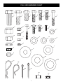
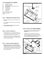
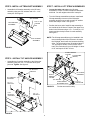
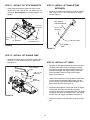
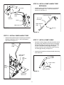
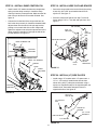
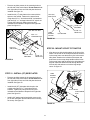
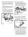
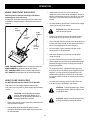
Owner's Manual
Model No. 486.24847
FRONT SCOOP TRACTOR ATTACHMENT
CAUTION:
Before using this product, read this
manual and follow all Safety Rules
and Operating Instructions.
IMPORTANT - READ THIS FIRST!!!
For Missing Parts or Assembly Questions
Please Call 866-576-8388
Mon.-Fri. 7 a.m.-5 p.m. CST.
FAX 217-728-2032 or e-mail [email protected]
Missing parts will be sent UPS in 24 hours directly to your home.
•
•
•
•
•
Safety
Assembly
Operation
Maintenance
Parts
Sears, Roebuck and Co., Hoffman Estates, IL 60179 U.S.A.
www.sears.com/craftsman
PRINTED IN U.S.A.
FORM NO. 49326 (1/05)
TABLE OF CONTENTS
WARRANTY .............................................................. 2
SAFETY RULES ........................................................ 3
FULL SIZE HARDWARE CHART ............................. 4
CARTON CONTENTS .............................................. 6
ASSEMBLY ............................................................... 7
OPERATION ............................................................ 14
MAINTENANCE ...................................................... 15
TROUBLESHOOTING ............................................ 15
REPAIR PARTS ILLUSTRATION .......................... 16
REPAIR PARTS LIST ............................................. 17
SLOPE GUIDE ........................................................ 19
PARTS ORDERING/SERVICE ................. Back Page
WARRANTY
LIMITED ONE YEAR WARRANTY ON CRAFTSMAN FRONT SCOOP TRACTOR ATTACHMENT
For one year from the date of purchase, when this scoop is maintained and lubricated according to the operating and
maintenance instructions in this owner's manual, Sears will repair any defect in material or workmanship free of
charge. If this scoop is used for commercial or rental purposes, this warranty applies for only 90 days from the date of
purchase.
This warranty does not cover repairs necessary because of operator negligence or abuse, including the failure to
maintain the equipment according to instructions contained in this owner's manual.
WARRANTY SERVICE IS AVAILABLE BY CONTACTING THE NEAREST SEARS SERVICE CENTER/
DEPARTMENT IN THE UNITED STATES.
This warranty applies only while this product is in the United States.
This warranty gives you specific legal rights, and you may also have other rights which vary from state to state.
Sears, Roebuck and Co., D/817 WA., Hoffman Estates, Chicago, IL 60179
The model number and serial number will be found on a
decal attached to the bucket.
You should record both the serial number and the date of
purchase and keep in a safe place for future reference.
2
MODEL NUMBER:
486.24847
SERIAL NUMBER:
__________________
DATE OF PURCHASE:
__________________
SAFETY RULES
Any power equipment can cause injury if operated improperly or if the user does not understand how to operate the equipment.
Exercise caution at all times, when using power equipment.
• Read this owner's manual before attempting to
• Never ram the scoop into material at high speed.
• Vehicle braking and stability may be affected with the
assemble or operate the scoop attachment.
• Read the vehicle owner's manual and know how to
•
•
•
•
•
operate your vehicle before using the scoop
attachment.
Never carry passengers in the scoop bucket. It has
not been designed to carry passengers.
Never allow children to operate the vehicle or the
scoop attachment.
Do not allow adults to operate the vehicle or scoop
attachment without proper instructions.
Always begin with the transmission in first (low) and
gradually increase speed as conditions permit.
Drive the tractor at reduced speed over rough terrain
and hillsides or near creeks and ditches to prevent
tipping over and loss of control. Do not drive too close
to a creek or ditch.
•
•
attachment of this scoop. Do not fill the scoop to
maximum weight capacity without checking the
capability of the vehicle to safely drive and stop with
the scoop attached.
Before operating vehicle on any grade (hill) refer to
the safety rules in the vehicle owner's manual
concerning safe operation on slopes. Refer also to
the slope guide on page 19 of this manual. Stay off
steep slopes!
Follow maintenance and lubrication instructions as
outlined in this manual.
Look for this symbol to point out important safety precautions. It means—Attention!!
Become alert!! Your safety is involved.
ACCESSORIES AND ATTACHMENTS
These accessories were available when the unit was purchased. They are also available at most Sears retail outlets and
service centers. Most Sears stores can order repair parts for you when you provide the model numbers of your tractor and
scoop.
WHEEL WEIGHT
3
FULL SIZE HARDWARE CHART
B
A
Q
L
E
D
C
I
H
G
F
K
J
U
R
M
X
S
W
V
N
T
Y
O
Z
P
AA
BB
CC
DD
EE
FF
GG
HH
4
PARTS NOT SHOWN FULL SIZE
JJ
II
LL
MM
KK
PARTS BAG CONTENTS
Not all parts will be needed for fit-up to any one tractor.
Discard uneeded parts after assembly is finished.
REF.
QTY.
DESCRIPTION
REF.
QTY.
DESCRIPTION
A
2
Hex Bolt, 5/8" x 1-1/2"
U
6
Lock Washer, 3/8"
B
2
Hex Bolt, 1/2" x 1-1/2"
V
3
Washer, 1/4"
C
3
Hex Bolt, 1/2" x 1"
W
8
Washer, 5/16"
D
2
Hex Bolt, 3/8" x 1-1/4"
X
3
Washer, 1/2" Small
E
4
Hex Bolt, 3/8" x 1"
Y
6
Washer, 5/8"
F
5
Hex Bolt, 5/16" x 1"
Z
2
Washer, 1/2" Large
G
5
Hex Bolt, 5/16" x 1-3/4"
AA
2
Washer, 3/4"
H
3
Hex Bolt, 1/4" x 1-3/4"
BB
2
Washer, 1"
I
2
Carriage Bolt, 5/16-18 x 1"
CC
3
Hairpin Cotter, Long
J
2
Carriage Bolt, 1/4-20 x 3/4"
DD
4
Hairpin Cotter, Short
K
1
Slotted Truss Head Bolt, 10-32 x 5/8"
EE
6
Cotter Pin, 1/8" x 1-1/4"
L
2
Nylock Nut, 5/8"
FFF
2
Cotter Pin, 1/8" x 1-1/2"
M
2
Nylock Nut, 1/2"
GG
4
Spacer, 1/2"
N
3
Nylock Jam Nut, 1/2"
HH
1
Spacer, 3/8" Small
O
2
Hex Nut, 3/8"
II
2
Clevis Pin
P
2
Nylock Nut, 3/8"
JJ
1
Compression Spring
Q
12
Nylock Nut, 5/16"
KK
6
Cable Tie
R
5
Nylock Nut, 1/4"
LL
2
Tilt Stop Bracket
S
1
Hex Nut, 1/4"
MM
1
Hose Clip
T
1
Nylock Nut, #10-32
5
ASSEMBLY
CARTON CONTENTS
1. Bucket Assembly
8. Right (GT) Side Plate
15. Lift Handle Tube
2. Pin Stop Bracket
9. Left (GT) Side Plate
16. Dump Handle Tube Extension
3. Lift Frame Assembly
10. Dump Control Rod
17. Dump Pivot Bracket
4. Lift Bracket Assembly
11. Lift Strap Assembly (2)
18. Lift Handle Tube Extension
5. Tilt Anchor Assembly
12. Tilt Bracket Assembly
19. Dump Control Pin
6. Right (LT) Side Plate
13. Attachment Rod
20. Lift Cable (Short)
7. Left (LT) Side Plate
14. Dump Handle Tube
21. Lift Cable (Long)
1
2
4
5
3
11
13
8
6
10
12
9
7
18
16
14
15
20
17
19
6
21
TOOLS REQUIRED FOR ASSEMBLY
(1)
(1)
(2)
(2)
(2)
(2)
(2)
(1)
5/16" x 1"
HEX BOLT
#2 Phillips Screwdriver
Standard Screwdriver
15/16" Wrenches (one should be box-end)
3/4" Wrenches
9/16" Wrenches
7/16" Wrenches
1/2" Wrenches
3/8" Wrench
5/16" WASHERS
PIN STOP
BRACKET
BUCKET
ASSEMBLY
ADDITIONAL ITEMS NEEDED
Ruler or Tape Measure
Grease
5/16"
NYLOCK NUT
STEP 1 - REMOVE PARTS FROM CARTON
•
Remove the hardware pack and all loose parts from
the carton.
•
Lay cardboard on floor to help prevent scratching of
painted parts.
•
3/8" NYLOCK NUT
3/8" x 1-1/4"
HEX BOLT
3/8" HEX NUT
FIGURE 1
Lay out and identify all the parts and hardware as
shown on pages 4 through 6.
STEP 4 - INSTALL LIFT FRAME ASSEMBLY
•
Apply grease to the mounting surface of the bucket
assembly and the inside of the lift frame arms.
See figure 2.
•
Assemble the lift frame assembly to the bucket
assembly using two 5/8 x 1-1/2" hex bolts and 5/8"
nylock nuts. Tighten, then loosen the nuts 1/4 turn,
or until the lift frame pivots freely. See figure 2.
STEP 2 - INSTALL TWO BOLTS
•
•
Assemble two 3/8" x 1-1/4" hex bolts and 3/8" hex
nuts, threading the nut all the way onto the bolt until it
is tight against the head of the bolt. See figure 1.
Install a nut/bolt assembly into the bucket assembly
and fasten using a 3/8" nylock nut. Tighten. Repeat
for the other side. See figure 1.
5/8" x 1-1/2"
HEX BOLT
LIFT FRAME
ASSEMBLY
APPLY
GREASE
STEP 3 - INSTALL PIN STOP BRACKET
•
APPLY
GREASE
Install the pin stop bracket to the top of the bucket
assembly using four 5/16" x 1" hex bolts, eight 5/16"
washers and four 5/16" nylock nuts. Center the bolts
in the slots of the pin stop bracket and the slots of the
bucket. Tighten the bracket so that it is square with
the bucket. See figure 1.
5/8" HEX BOLT
5/8" NYLOCK NUTS
FIGURE 2
7
APPLY GREASE
STEP 5 - INSTALL LIFT BRACKET ASSEMBLY
STEP 7 - INSTALL LIFT STRAP ASSEMBLIES
• Assemble the lift bracket assembly to the lift frame
•
Loosen the bolts and nuts on the lift strap
assemblies 1/4 turn or until the straps will slide back
and forth. You will retighten them later in step 24.
•
Turn the lift strap assemblies as shown. Install each
lift strap assembly to an arm of the lift bracket
assembly and then secure with a small 1/2" washer
and a short hairpin cotter. See figure 5.
•
Position the lower end of each lift strap assembly to
the outside of the lift frame. Fasten to the upper front
holes in the lift frame using a 1/2" x 1" clevis pin, 1/2"
spacer and short hairpin cotter for each assembly.
See figure 5.
assembly using two 5/8" washers and 1/8" x 1-1/4"
cotter pins. See figure 3.
5/8" WASHER
LIFT BRACKET
ASSEMBLY
1/8" x 1-1/4"
COTTER
PIN
NOTE: The lift strap assemblies may be installed in the
rear mounting holes of the lift frame to increase
the lift height, but this will also increase the lifting
effort. The front holes give a lift height of about 61/2" and require 28 lbs. of force to lift a 150 lb
load. The rear holes will give a lift height of about
8-1/2" and require 35 lbs. of force.
LIFT FRAME
ASSEMBLY
FIGURE 3
SHORT HAIRPIN
COTTER
1/2" WASHER
(SMALL)
STEP 6 - INSTALL TILT ANCHOR ASSEMBLY
•
Assemble the tilt anchor assembly to the lift bracket
assembly using two 1/2" x 1" hex bolts and nylock
jam nuts. Tighten. See figure 4.
1/2" NYLOCK
JAM NUTS
SHORT
HAIRPIN
COTTER
1/2" SPACER
TILT ANCHOR
ASSEMBLY
UPPER FRONT
MOUNTING HOLE
1/2" x 1"
HEX BOLT
FIGURE 5
LIFT
BRACKET
ASSEMBLY
1/2" x 1"
HEX BOLT
FIGURE 4
8
Bucket removed for clarity.
LIFT STRAP
ASSEMBLY
1/2" x 1"
CLEVIS PIN
STEP 8 - INSTALL TILT BRACKET ASSEMBLY
STEP 9 - INSTALL DUMP PIVOT BRACKET
•
NOTE: If you mounted the lift strap assemblies in Step 7
to the rear holes in the lift frame for increased
lifting height, you need to replace the 3/8" spacer
on the tilt bracket assembly with the smaller 3/8"
spacer from the parts bag at this time.
•
•
•
Install a 1/8" x 1-1/2" cotter pin to the inside hole in
the shaft shown in figure 9, and then install a 1"
washer onto the shaft. Apply grease to the end of the
shaft and install the dump pivot bracket assembly
onto the shaft. Install a 1" washer onto the shaft and
secure it using a 1/8" x 1-1/2" cotter pin. See figure 7.
Loosen the bolts and nuts on the tilt bracket
assembly 1/4 turn or until the two plates will slide
back and forth. You will retighten them later in step
23. See figure 6.
1/8" x 1-1/2"
COTTER PIN
1" WASHERS
Lightly apply grease to the end of the arm on the tilt
anchor assembly and install the tilt bracket assembly
to the arm using a 1/2" x 1" hex bolt and 1/2" nylock
jam nut. Tighten. Loosen the nut 1/4 turn, or until the
tilt bracket assembly pivots freely. See figure 6.
1/8" x 1-1/2"
COTTER PIN
APPLY
GREASE
Install a 1/4" x 1-3/4" hex bolt through a 1/4" washer
and then through the end of the extension spring on
the tilt bracket assembly. Next, install a 1/4" hex nut
all the way onto the threads of the bolt. Finally install
the end of the bolt into the hole in the arm of the tilt
anchor assembly and secure using a 1/4" nylock nut.
Tighten. See figure 6.
1/4" NYLOCK NUT
DUMP PIVOT
BRACKET
FIGURE 7
1/2" x 1"
HEX BOLT
TILT ANCHOR
ASSEMBLY
STEP 10 - INSTALL DUMP CONTROL ROD
•
Install a 1/8" x 1-1/4" cotter pin into the inside hole in
each end of the dump control rod. Spread the ends of
the cotter pins and wrap around the rod. Install a 5/8"
washer onto each end of the control rod. See figure 8.
•
Install the dump control rod to the dump pivot bracket
and bucket. Fasten using two 5/8" washers and 1/8" x
1-1/4" cotter pins. Spread the ends of the cotter pins
and wrap around the rod. See figure 8.
1/4" HEX NUT
1/4" WASHER
1/4" x 1-3/4"
HEX BOLT
APPLY
GREASE
1/2" NYLOCK
JAM NUT
TILT BRACKET
ASSEMBLY
1/8" x 1-1/4"
COTTER PIN
FIGURE 6
5/8" WASHERS
1/8" x 1-1/4"
COTTER
PINS
1/8" x 1-1/4"
COTTER PIN
5/8" WASHERS
FIGURE 8
9
DUMP
CONTROL
ROD
STEP 11 - INSTALL TILT STOP BRACKETS
•
STEP 13 - INSTALL LIFT HANDLE TUBE
EXTENSION
Install a tilt stop bracket to each side of the bucket
using a 1/4" x 3/4" carriage bolt, 1/4" washer and 1/4"
nylock nut. Do not tighten the nuts until step 25. See
figure 9.
•
Install the lift handle tube extension on the lift handle
tube using a 1/4" x 1-3/4" hex bolt and 1/4" nylock
nut. See figure 11.
LIFT HANDLE
TUBE EXTENSION
TILT STOP
BRACKET
1/4" NYLOCK
NUT
1/4" WASHER
1/4" x 1-3/4"
HEX BOLT
1/4" x 3/4"
CARRIAGE BOLT
1/4" NYLOCK NUT
LIFT HANDLE
TUBE
FIGURE 9
FIGURE 11
STEP 12 - INSTALL LIFT HANDLE TUBE
•
Install the lift handle tube on the index bracket using
two 5/16" x 1-3/4" hex bolts and 5/16" nylock nuts.
See figure 10.
5/16"
NYLOCK NUTS
STEP 14 - INSTALL LIFT CABLE
•
Squeeze the lift trigger and slide the anchor end of the
lift (short) cable into the hole in the trigger. Release
the trigger and guide the cable through the slot in the
bottom of the trigger and trigger housing. Insert the
end of the plastic cable covering into the trigger
housing. See figure 12.
•
Connect the hooked end of the lift cable into the index
rod, and install the threaded cable adjuster into the
notch in the top of the index bracket, placing a nut on
each side of the notch. See figure 12.
•
Adjust the cable adjuster nuts so that when the trigger
is squeezed, the bottom of the index rod raises
enough to release from the latched position. The index
rod should also lower far enough to lock in the latched
position when the trigger is released. See figure 12.
•
Attach the lift cable to the lift handle using three cable
ties.
LIFT HANDLE
TUBE
5/16" x 1-3/4"
HEX BOLT
INDEX
BRACKET
FIGURE 10
10
STEP 16 - INSTALL DUMP HANDLE TUBE
EXTENSION
LIFT TRIGGER
•
LIFT CABLE
Install the dump handle tube extension on the dump
handle tube using a 1/4" x 1-3/4" hex bolt and 1/4"
nylock nut. See figure 14.
CABLE
ADJUSTMENT
NUTS
DUMP HANDLE
TUBE EXTENSION
CABLE
ANCHOR
1/4" x 1-3/4"
HEX BOLT
HOOK
DUMP HANDLE
TUBE
INDEX ROD
1/4" NYLOCK
NUT
FIGURE 12
FIGURE 14
STEP 15 - INSTALL DUMP HANDLE TUBE
•
Install the dump handle tube to the dump pivot bracket
assembly using three 5/16" x 1-3/4" hex bolts and
nylock nuts. See figure 13.
STEP 17 - INSTALL DUMP CABLE
•
Squeeze the dump trigger and slide the anchor end of
the dump (long) cable wire into the hole in the trigger.
Release the trigger and guide the cable wire through
the slot in the bottom of the trigger and trigger
housing. Insert the end of the plastic cable covering
into the trigger housing. See figure 15.
•
Attach the dump cable to the dump handle tube using
three cable ties.
DUMP
HANDLE
TUBE
DUMP PIVOT
BRACKET
5/16"
NYLOCK
NUT
DUMP CABLE
5/16"
NYLOCK
NUTS
DUMP TRIGGER
FIGURE 15
5/16" x 1-3/4"
HEX BOLTS
FIGURE 13
11
STEP 18 - INSTALL DUMP CONTROL PIN
STEP 19 - INSTALL HOSE CLIP AND SPACER
•
•
Secure the dump cable to the back of the bucket using
a hose clip, #10 x 5/8" truss-head bolt and #10-32
nylock nut. See figure 17.
•
Store the unused 3/8" spacer from step 7 on the lift
frame using a 5/16" x 1" hex bolt and nylock nut. See
figure 17.
•
Install a small 1/2" washer and then the compression
spring onto the dump control pin. Install the dump
control pin into the pin stop bracket. Make sure the flat
side of the pin faces to the front when finished. See
figure 16.
Connect the hooked end of the dump cable into the
hole in the dump control pin. Install the threaded cable
adjuster down into the notch in the pin stop bracket,
placing a nut on each side of the notch. Adjust and
tighten the adjuster nuts so that the tapered end of the
dump control pin extends 3/4" through the side of the
pin stop bracket. See figure 16.
3/8" SPACER
5/16" x 1"
HEX BOLT
5/16"
NYLOCK
NUT
#10-32 NYLOCK NUT
DUMP CONTROL PIN
3/4"
PIN STOP
BRACKET
DUMP CONTROL PIN
SMALL 1/2" WASHER
HOSE
CLIP
SPRING
HOOK
#10 x 5/8"
TRUSS
HEAD BOLT
FIGURE 17
CABLE
ADJUSTER
STEP 20 - INSTALL (LT) SIDE PLATES
•
PIN STOP
BRACKET
Install a large 1/2" washer and a 1/2" spacer onto a
1/2" x 1-1/2" hex bolt. Install the bolt into the hole
shown in the left (LT) side plate, and fasten using a
nylock nut. Repeat the step for the right side plate, but
install the bolt, flat washer and spacer from the
opposite direction. See figure 18.
FIGURE 16
LEFT (LT)
SIDE PLATE
1/2" NYLOCK
NUT
LARGE 1/2"
WASHER
USE THIS HOLE
1/2" SPACER
FIGURE 18
12
1/2" x 1-1/2"
HEX BOLT
•
Remove any bolts present in the mounting holes on
the left side of the tractor frame. Do not remove bolts
from right side of frame until left side plate has been
installed. See figure 19.
•
Install the left (LT) side plate on the tractor with the
spacer to the outside. Fasten to the tractor frame
using three 3/8" x 1" hex bolts and 3/8" lock washers
and one 5/16" x 1" carriage bolt and 5/16" nylock nut.
Tighten 3/8" bolts only until the are snug and
lockwashers are flattened. Repeat for the right side
plate. See figure 19.
LEFT (GT)
SIDE PLATE
(2) 3/8 LOCK
WASHERS
(2) 3/8" x 1"
HEX BOLTS
5/16" NYLOCK NUT
LONG
HAIRPIN
COTTER
5/16 " x 1"
CARRIAGE BOLT
3/4" WASHER
FIGURE 20
LEFT (LT)
SIDE PLATE
STEP 22 - MOUNT SCOOP TO TRACTOR
•
(3) 3/8" LOCK
WASHERS
(3) 3/8" x 1"
HEX BOLTS
FIGURE 19
Align the scoop with the side plates on the front of the
tractor. Lift the rear of the scoop and slide the notches
in the scoop frame onto the bolts or pins in the tractor
side plates. Stand on the left side of the tractor and
push down on the scoop dump handle until the holes
in the scoop frame and the holes in the side plates are
aligned. Install the attachment rod through the holes
from the left side and secure it with a long hairpin
cotter. Se figure 21.
DUMP HANDLE
STEP 21 - INSTALL (GT) SIDE PLATES
•
Remove any bolts present in the mounting holes on
the left side of the tractor frame. Do not remove bolts
from right side of frame until left side plate has been
installed. See figure 20.
•
Install the left (GT) side plate with the pin to the
outside using two 3/8" x 1" hex bolts and lock
washers. Tighten only until bolts are snug and
lockwashers are flattened. Repeat for the right side
plate. See figure 20.
•
LONG
HAIRPIN
COTTER
BOLT OR PIN
ATTACHMENT
ROD
Install a 3/4" washer and a long hairpin cotter to the
pin in each side plate. Remove them while mounting
the scoop. See figure 20.
SCOOP
ASSEMBLY
FIGURE 21
13
STEP 23 - ADJUST TILT BRACKET ASSEMBLY
STEP 24 - ADJUST LIFT STRAPS
•
Lower the scoop assembly onto a smooth level
surface. For normal use, let the bottom of the bucket
rest flat on the ground. For more aggressive scraping
action, place 1/4" shims under the rear of the bucket
at each end.
•
•
Swing the tilt bracket forward to check for clearance
with the pin stop bracket. There should be a small gap
between the tilt bracket and the side of the pin stop
bracket. If not, adjust the position of the pin stop
bracket side to side.
•
Make sure the nuts and bolts in the lift straps are
loose enough to turn by hand. Stand on the right side
of the scoop and hold the lift handle as far forward
as it will go while you tighten one of the nuts in the lift
straps.You can let go of the lift handle to tighten the
other three nuts in the lift straps. See figure 23.
LIFT HANDLE
Make sure the two bolts in the tilt bracket are loose
enough to turn by hand. Align the tilt bracket so that
the dump control pin snaps into the hole in the tilt
bracket. The tapered end of the pin should extend
clear through the tilt bracket. Tighten the two bolts
and nuts in the tilt bracket. See figure 22.
TIGHTEN
NUTS
LIFT STRAP
ASSEMBLIES
FIGURE 23
DUMP
CONTROL PIN
STEP 25 - ADJUST TILT STOP BRACKETS
•
TIGHTEN
Raise the scoop until it locks in the TRANSPORT
position. Push the tilt stop brackets on each side of the
bucket down against the lift frame arms, and tighten
the nuts. See figure 24.
TILT STOP
BRACKET
TILT BRACKET
PIN STOP BRACKET
FIGURE 22
LIFT FRAME ARM
FIGURE 24
STEP 26 - CHECK DUMPING OPERATION
•
14
With the scoop in the transport position, squeeze the
dump trigger and push down on the dump handle to
dump the bucket. Release the dump trigger and lift up
on the handle to lock the bucket in the upright position.
If the dump control pin passes underneath the tilt
bracket instead of locking into it, move the pin stop
bracket on top of the bucket farther towards the rear. If
this does not work, repeat steps 23, 24 and 25.
OPERATION
KNOW YOUR FRONT END SCOOP
•
Always test to make sure your vehicle has
adequate power and braking capabilities whenever
hauling a substantial amount of weight in your front
end scoop. Use extra caution when operating on
slopes.
•
For best handling and traction, distribute the weight
of the load evenly in the bucket.
Read this owner's manual and safety rules before
operating your front end scoop.
Compare the illustration below with your front end scoop
to familiarize yourself with the various controls and their
locations.
LIFT
HANDLE
CAUTION: Never ram the scoop into
material at high speeds.
DUMP
HANDLE
LIFT
TRIGGER
LEVER
DUMP
TRIGGER
LEVER
DUMP TRIGGER LEVER Press to release the dump pin.
DUMP HANDLE Press down to dump the bucket.
LIFT TRIGGER LEVER Press to release the index pin.
LIFT HANDLE Press down to lift the bucket assembly.
HOW TO USE YOUR SCOOP
DO NOT EXCEED 200 LB. CAPACITY OF BUCKET
•
Keep the lift handle locked in the raised position
when tilting the scoop bucket forward to dump.
•
The lift handle must be locked in the raised position
to allow the dump handle to lock the scoop bucket
back in the upright position after dumping.
•
Do not scrape or push material with the scoop
bucket while it is tilted forward.
•
Add wheel weights for improved traction when
using the scoop.
•
To dump material from the bucket, squeeze the
dump trigger and push the dump tube handle down.
Release the trigger before returning the bucket to
the upright position.
•
To lower the bucket, squeeze the lift trigger and
then lift up on the lift handle. If the trigger is hard to
depress, you may need to push down on the lift
handle while squeezing, and then lift up. Release
the trigger before retuning the bucket to the raised
position.
•
Do not exceed mowing speed (3 mph) when the
front end scoop is attached to the tractor.
One cubic foot of dirt weighs approximately 80 lbs.
One cubic foot of dry sand or gravel weighs approximately
100 lbs.
CAUTION: To avoid possible injury, before
dumping the bucket, make sure that no one
is near the bucket.
CAUTION: Vehicle braking and stability
may be affected with the addition of an
accessory or an attachment. Be aware of
changing conditions on slopes.
•
Refer to the vehicle owner's manual for instructions on
safe operation on slopes.
•
Use the slope guide provided on page 23 of this
manual to determine whether slope angle is too steep
for safe operation.
CAUTION: Always lower the scoop bucket
to the ground before leaving the tractor.
15
MAINTENANCE
CUSTOMER RESPONSIBILITIES
•
Read and follow the maintenance schedule and the maintenance procedures listed in this section.
e
us se on ge
ch ch u eas tora
a
e ea
s es
e
y
r
for fter ver efo
e
E
B
A
B
MAINTENANCE SCHEDULE
Fill in dates as you
complete regular service.
Check for loose fasteners
Cleaning
Lubricate
Service Dates
X
X
X
CHECK FOR LOOSE FASTENERS
LUBRICATION
•
•
•
Before each use make a thorough visual check of
the front end scoop for any bolts and nuts which
may have loosened. Retighten any loose bolts and
nuts.
•
Lightly oil all pivot points on the scoop lift mechanism.
Lightly oil the surface on the scoop bucket where
the attachment lift frame pivots.
Apply a good grade of spray lubricant to the trigger
assemblies on the lift handle and dump handle.
CLEANING
•
•
•
After each use, clean off any dirt and debris from
the scoop bucket lift frame.
Before storing at the end of each season, rinse off
the scoop bucket and scoop lift frame. Allow to dry
thoroughly. Paint any exposed metal surfaces to
protect from rust.
Store in a clean, dry area.
TROUBLESHOOTING
PROBLEM
CAUSE
CORRECTION
Scoop won't lock into
raised/transport postion.
1. Index rod is jamming.
2. Frame is hitting the tilt stop
brackets.
1. Apply grease to the bottom slot in the
lift bracket, where the index rod slides.
2. Adjust the tilt stop brackets as
instructed on page 14.
Scoop bucket won't lock into level
position.
1. Dump control pin is not aligned with
the tilt bracket.
1. Adjust tilt bracket and lift straps as
instructed on page 14.
Lift handle trigger won't release
scoop from the transport position.
1. Index rod is jamming.
1. Apply grease to the bottom slot in the
lift bracket, where the index rod slides.
2. Adjust cable nuts as instructed on
page 11.
2. Lift cable is not adjusted properly.
Dump handle trigger won't
release bucket to dump.
1. Dump control cable is not adjusted
properly.
2. Latch mechanism is not adjusted
properly.
1. Adjust parts as instructed for figure
16 on page 11.
2. Adjust parts as instructed for figure
22 on page 14.
Bucket is becoming more difficult
to tilt up or down.
1. Debris is lodged between bucket
assembly and lift frame.
1. Remove all debris from between the
bucket assembly and lift frame.
16
NOTES
17
PARTS
REPAIR PARTS FOR MODEL 486.24847
5
4
36
37
2
3
6
1
22
23
80
13
34
29
10
7
8
30
31
4
33
5
38
11
12
13
1
19
17
10
18
28
23
39
15 16
6
13
77
20
27
21
22
14
76
24
73
51
82
32
29
9
79
78
75
81
69
15
19
67
8
42
25 26
43
44
1
26
72 14
75
74
71
28 45
10
41
52
40
44
48
63
70
47 15
49
14
15 46
57
51
52
50
58
52
45
45
52
10
54
45
63
68
13
13
43
20
61
59 60
35
42
42
51
56
55 17
65
66
68
67
14
53
43
32
21
64
13
52
45
62
18
7
REPAIR PARTS FOR MODEL 486.24847
REF.
NO.
1
2
3
4
5
6
7
8
9
10
11
12
13
14
15
16
17
18
19
20
21
22
23
24
25
26
27
28
29
30
31
32
33
34
35
36
37
38
39
40
41
42
PART
NO.
QTY.
1509-69
726-0178
49265
49266
47674
47554
712-0127
47317
47555
47189
47369
47368
47810
HA21362
43070
25350
43063
25343
741-0192
R1917616
43055
43001
63755
43178
64964
48115
63675
25510
43343
43020
R19172410
47364
712-3083
43003
712-0261
63568
63569
49270
47066
49271
49483
43601
3
6
1
2
2
2
2
2
1
5
1
1
14
8
6
4
8
1
2
3
4
10
2
1
1
3
1
2
3
2
2
4
2
6
2
1
1
1
1
1
1
3
REF.
NO.
DESCRIPTION
Hex Bolt, 1/4-20 x 1-3/4" (Grade 5)
Cable Tie
Lift Tube Handle Extension
Oval Screw, 10-24 x 1-1/2"
Plastic Plug, 1-1/4" O.D. Tube
Trigger Housing Assembly
Square Nut, #10-24
Grip, Black
Cable, Lift
Nylock Nut, 1/4"
Roll Pin, 3/16" x 1-3/4"
Roll Pin, 5/16" x 1-3/4"
Nylock Nut, 5/16-18
Nylock Nut, 3/8-16
Flat Washer, 3/8"
Lift Strap
Hex Bolt, 5/16-18 x 1" (Grade 5)
Lift Bracket
Flange Bearing with Flats
Flat Washer, 1/2" x 1" (Small)
Hairpin Cotter, 3/32" x 1.8"
Hex Bolt, 3/8-16 x 1" (Grade 5)
Trigger Assembly
Hex Nut, 1/4-20
Tilt Anchor Assembly
Nylock Jam Nut, 1/2-13
Lift Arm Assembly
Mounting Bracket
Hairpin Cotter, 3/32" x 2-5/16"
Hex Bolt, 1/2-13 x 1-1/2" (Grade 5)
Flat Washer, 1/2" x 1-1/2" (Large)
Spacer, 0.52" x 0.75" x 0.4"
Nylock Nut, 1/2-13
Lock Washer, 3/8"
Nylock Nut, 5/8-11
Right (GT) Side Plate
Left (GT) Side Plate
Dump Handle Tube Extension
Attachment Rod
Dump Handle Tube
Dump Control Cable)
Washer, 1.59" x 1.032" x 0.60"
* Purchase Common Hardware Locally
19
43
44
45
46
47
48
49
50
51
52
53
54
55
56
57
58
59
60
61
62
63
64
65
66
67
68
69
70
71
72
73
74
75
76
77
78
79
80
81
82
PART
NO.
QTY.
43093
710-0865
R19212016
25362
64983
HA6441
41576
64963
43084
43010
64968
49273
49268
48905
46055
25335
47171
HA23761
43346
64962
43015
43087
44950
25331
736-0142
43081
44326
710-0367
25408
23625
43000
44062
142
R19131316
63773
48049
732-0306
49264
43009
25562
25563
49326
3
3
6
1
1
1
1
1
5
6
1
1
1
1
1
1
1
1
1
1
3
2
2
2
3
8
2
2
1
1
1
2
1
2
1
1
1
1
2
1
1
1
DESCRIPTION
Cotter Pin, 1/8" x 1-1/2"
Hex Bolt, 1/2-13 x 1" (Grade 5)
Flat Washer, 5/8" x 1-1/4" x 16 Ga.
Tilt Bracket Extension Strap
Tilt Bracket
Hex Bolt, 3/8-16 x 2" (Grade 5)
Hex Bolt, 3/8-16 x 1-3/4" (Grade 5)
Lift Frame Assembly
Hex Bolt, 5/16-18 x 1-3/4" (Grade 5)
Cotter Pin, 1/8" x 1-1/4"
Dump Pivot Bracket
Dump Control Rod
Dump Control Pin
Compression Spring
Spring Pin, 1/8" x 1"
Pin Stop Bracket
Nylock Nut, #10-32
Hose Clamp
Truss-Head Bolt, #10-32 x 5/8"
Bucket Assembly
Hex Nut, 3/8-16
Hex Bolt, 3/8-16 x 1-1/4" (Grade 5)
Carriage Bolt, 1/4-20 x 3/4" (Grade 5)
Tilt Stop Bracket
Flat Washer, 1/4"
Flat Washer, 5/16"
Carriage Bolt, 5/16" x 1" (Grade 5)
Hex Bolt, 5/8-11 x 1-1/2" (Grade 5)
Spacer, 3/8" I.D. x 7/8"O.D. x 3/8"
Spacer, 3/8" I.D. x 5/8"O.D. x 1/4"
Extension Spring
Clevis Pin, 1/2" x 1"
Cotter Pin, 1/8" x 3/4"
Flat Washer, 3/8" x 13/16" x 1/16"
Index Bracket Assembly
Index Rod
Spring, Compression
Lift Handle Tube
Flat Washer, 3/4"
Right (LT) Side Plate
Left (LT) Side Plate
Owner's Manual
NOTES
20
NOTES
21
NOTES
22
SLOPE GUIDE
(Keep this sheet in a safe place for future reference.)
Use this guide to determine if a slope is safe for the operation of your tractor and scoop.
Refer also to the instructions in your vehicle owner's manual.
SIGHT AND HOLD THIS LEVEL WITH A VERTICAL TREE
A POWER POLE
A CORNER OF A BUILDING
OR A FENCE POST
FO
L
D
A
LONG
DOTTE
D LIN
E
,
R
E
PRESE
NTING
A
1
0
D
EGREE
SLOPE
CAUTION: DO NOT OPERATE YOUR TRACTOR AND SCOOP ON A SLOPE
IN EXCESS OF 10 DEGREES. BE SURE OF YOUR TRACTOR'S TOWING
AND BRAKING CAPABILITIES BEFORE OPERATING ON A SLOPE. AVOID
ANY SUDDEN TURNS OR MANEUVERS WHILE ON A SLOPE.
23
Get it fixed, at your home or ours!
For repair of major brand appliances in your own home…
no matter who made it, no matter who sold it!
1-800-4-MY-HOME SM Anytime, day or night
(1-800-469-4663)
www.sears.com
To bring in products such as vacuums, lawn equipment and electronics
for repair, call for the location of your nearest Sears Parts & Repair Center.
1-800-488-1222
Anytime, day or night
www.sears.com
For the replacement parts, accessories and owner’s manuals
that you need to do-it-yourself, call Sears PartsDirect SM !
1-800-366-PART
(1-800-366-7278)
6 a.m. – 11 p.m. CST,
7 days a week
www.sears.com/partsdirect
To purchase or inquire about a Sears Service Agreement:
1-800-827-6655
7 a.m. – 5 p.m. CST, Mon. – Sat.
Para pedir servicio de reparación a domicilio,
y para ordenar piezas con entrega a domicilio:
1-888-SU-HOGAR
Au Canada pour service en français:
1-877-LE-FOYER SM
SM
(1-877-533-6937)
(1-888-784-6427)
HomeCentral
SM
® Registered Trademark / ™ Trademark of Sears, Roebuck and Co.
© Sears, Roebuck and Co.
® Marca Registrada / ™ Marca de Fábrica de Sears, Roebuck and Co.