1
PS/2 Displays Maintenance Manual
Book Cover
COVER Book Cover
-------------------------------------------------------------------------IBM Personal System/2
Display
Hardware
Maintenance
Manual - Vol. 1
January 1993
Document Number SA38-0053-00
Part Number 68G2616
--------------------------------------------------------------------------
¦ Copyright IBM Corp. 1993
COVER - 1
PS/2 Displays Maintenance Manual
Edition Notice
EDITION Edition Notice
This booklet is a component of PS/2 Bill of Forms number SBOF-2480-00.
First Edition (January 1993)
The following paragraph does not apply to the United Kingdom or any
country where such provisions are inconsistent with local law:
INTERNATIONAL BUSINESS MACHINES CORPORATION PROVIDES THIS PUBLICATION
"AS IS" WITHOUT WARRANTY OF ANY KIND, EITHER EXPRESS OR IMPLIED,
INCLUDING, BUT NOT LIMITED TO, THE IMPLIED WARRANTIES OF
MERCHANTABILITY OR FITNESS FOR A PARTICULAR PURPOSE. Some states do
not allow disclaimer of express or implied warranties in certain
transactions, therefore, this statement may not apply to you.
This publication could include technical inaccuracies or typographical
errors. Changes are periodically made to the information herein;
these changes will be incorporated in new editions of the publication.
IBM may make improvements and/or changes in the product(s) and/or the
program(s) described in this publication at any time.
It is possible that this publication may contain reference to, or
information about, IBM products (machines and programs), programming,
or services that are not announced in your country. Such references
or information must not be construed to mean that IBM intends to
announce such IBM products, programming, or services in your country.
Requests for technical information about IBM products should be made
to your IBM Authorized Dealer or your IBM Marketing Representative.
IBM may have patents or pending patent applications covering subject
matter in this document. The furnishing of this document does not
give you any license to these patents. You can send license
inquiries, in writing, to the IBM Director of Commercial Relations,
IBM Corporation, Armonk NY 10504.
¦ Copyright International Business Machines Corporation 1993. All
rights reserved.
Note to U.S. Government Users -- Documentation related to restricted
rights -- Use, duplication or disclosure is subject to restrictions
set forth in GSA ADP Schedule Contract with IBM Corp.
¦ Copyright IBM Corp. 1993
EDITION - 1
PS/2 Displays Maintenance Manual
Notices
FRONT_1 Notices
Any reference to an IBM licensed program or other IBM product in this
publication is not intended to state or imply that only the IBM program or
other product may be used. Any functionally equivalent program that does
not infringe any IBM intellectual property rights may be used instead of
the IBM product. Evaluation and verification of operation in conjunction
with other products, except those expressly designated by IBM, is the
user's responsibility.
The warranty terms and conditions applicable in the country of purchase in
respect of an IBM product are available from the supplier. Please retain
them with your proof of purchase.
The following terms, denoted by a star ((*)), used in this publication,
are trademarks or service marks of the International Business Machines
Corporation in the United States or other countries:
IBM
Personal System/2
PS/2
The following terms, denoted by a double star ((**)), used in this
publication, are trademarks or service marks of other companies:
Minolta
Torx
Minolta Corporation
Textron Incorporated
No statements contained in this publication shall affect the statutory
rights of consumers.
¦ Copyright IBM Corp. 1993
FRONT_1 - 1
PS/2 Displays Maintenance Manual
About this Manual
PREFACE About this Manual
This manual contains hardware and maintenance information previously
contained in the Hardware Maintenance Reference and Hardware Maintenance
Service booklets for IBM (*) Personal System/2 (*) Displays. The
materials have been combined and condensed where reference information and
service procedures are the same for all displays. This information
appears in the first part of this book, "Part I. General Service
Information."
Information specific to each display appears in the chapters listed under
the second part of this book, "Part II. Display-Specific Service
Information." These chapters include all removal and replacement steps and
service procedures that apply only to that specific display.
The third part of the book, "Part III. Parts Catalog," lists all parts and
parts numbers for serviceable displays, lists all Element Exchange
displays with part numbers, and includes a complete list of the tools and
test equipment needed for servicing displays of any type.
To use this manual:
1.
2.
3.
4.
5.
6.
7.
Determine which display you will be servicing
Use the diagnostic guide to pinpoint problems
Follow the common removal procedures to gain access to the display
components you will be servicing
refer to the display-specific removal procedures for components
particular to that display
Continue to the display-specific service information chapter for the
display you are servicing for:
function checks
pattern checks
Consult "Part III. Parts Catalog" for parts numbers of components you
must replace
Return to the removal and replacement procedures to replace parts on
the display
Use display-specific adjustment procedures to return the display to
normal function.
(*) Trademark of IBM Corporation.
"Notices" in topic FRONT_1.
For a list of trademarks, see
¦ Copyright IBM Corp. 1993
PREFACE - 1
PS/2 Displays Maintenance Manual
Table of Contents
CONTENTS Table of Contents
COVER
Book Cover
EDITION
Edition Notice
FRONT_1
Notices
PREFACE
About this Manual
CONTENTS
Table of Contents
FRONT_2
Safety
FRONT_2.1
Safety Labels
FRONT_2.2
Safety at Work
FRONT_2.3
Cathode Ray Tube (CRT) Safety
FRONT_2.3.1
Storage of CRTs
FRONT_2.3.2
Maintenance and Installation of CRTs
FRONT_2.3.3
Disposal of CRTs
1.0
Part I. General Service Information
1.1
1. Operation
1.1.1
Display Modes
1.1.2
Operator Controls and Power-On Indicator
1.1.2.1
Contrast Control
1.1.2.2
Brightness Control
1.1.2.3
Power-On Indicator
1.1.3
Powering Off the System
1.2
2. Diagnostic Guide
1.2.1
Initial Checks
1.2.1.1
Visual check 0100
1.2.1.2
Power check 0110
1.2.2
Self-Test
1.2.3
Basic Function and Pattern Checks and Adjustments
1.2.4
Degaussing
1.3
3. Removal and Replacement
1.3.1
Tilt Swivel Stand
1.3.2
Lift Tilt Swivel Stand
1.3.3
Rear Cover
1.3.3.1
Rear Covers, Type 1
1.3.3.2
Rear Cover, Type 2
1.3.4
High Voltage Discharge Procedure
1.3.5
Card Tray Assemblies
1.3.6
Signal Cable
1.3.7
Integrated Tube Component (ITC)
1.3.8
Safety Check for Chassis Ground
2.0
Part II. Display-Specific Service Information
2.1
4. 6318/8511/8518-Specific Information
2.1.1
Display-Specific Removals and Replacements
2.1.1.1
Tilt Swivel Stand
2.1.1.2
Rear Cover
2.1.1.3
Card Tray Assembly
2.1.1.4
Signal Cables
2.1.1.5
Integrated Tube Component (ITC)
2.1.2
Functional Checks and Adjustments
2.1.2.1
Function Checks
2.1.2.2
Pattern Checks
2.1.2.3
Adjustment Procedures
2.1.3
Specifications
2.1.3.1
Physical Characteristics
2.1.3.2
Functional Characteristics
2.1.4
Locations 6318/8511/8518 Display
2.1.4.1
Safety Grounds
2.1.4.2
Parts Locations
2.2
5. 8513-Specific Information
2.2.1
Display-Specific Removals and Replacements
2.2.1.1
Tilt Swivel Stand
2.2.1.2
Rear Cover
2.2.1.3
Control Bridge Assembly
2.2.1.4
Card Tray Assembly
2.2.1.5
Integrated Tube Component (ITC)
2.2.2
Functional Checks and Adjustments
2.2.2.1
Function Checks
2.2.2.2
Pattern Checks
2.2.2.3
Adjustment Procedures
2.2.3
Specifications
2.2.3.1
Physical Characteristics
2.2.3.2
Functional Characteristics
2.2.4
Locations
2.2.4.1
Card Locations
2.2.4.2
Cable Connection Locations
2.3
6. 8515-Specific Information
2.3.1
Display-Specific Removals and Replacements
2.3.1.1
Tilt Swivel Stand
2.3.1.2
Rear Cover
2.3.1.3
Shield Cover
2.3.1.4
Card Tray Assembly
2.3.1.5
Signal Cable
2.3.1.6
Integrated Tube Component (ITC)
2.3.2
Functional Checks and Adjustments
2.3.2.1
Function Checks
¦ Copyright IBM Corp. 1993
CONTENTS - 1
PS/2 Displays Maintenance Manual
Table of Contents
2.3.2.2
2.3.2.3
2.3.3
2.3.3.1
2.3.3.2
2.3.4
2.3.4.1
2.3.4.2
2.4
2.4.1
2.4.1.1
2.4.2
2.4.2.1
2.4.2.2
2.4.3
2.4.4
2.4.4.1
2.5
2.5.1
2.5.1.1
2.5.1.2
2.5.1.3
2.5.1.4
2.5.1.5
2.5.1.6
2.5.1.7
2.5.2
2.5.2.1
2.5.2.2
2.5.2.3
2.5.2.4
2.5.3
2.5.3.1
2.5.3.2
2.5.3.3
2.5.4
2.5.4.1
2.5.4.2
2.5.4.3
2.6
2.6.1
2.6.1.1
2.6.1.2
2.6.1.3
2.6.1.4
2.6.1.5
2.6.2
2.6.2.1
2.6.2.2
2.6.2.3
2.6.3
2.6.3.1
2.6.3.2
2.6.4
2.6.4.1
2.6.4.2
2.7
2.7.1
2.7.1.1
2.7.1.2
2.7.1.3
2.7.1.4
2.7.1.5
2.7.2
2.7.2.1
2.7.2.2
2.7.2.3
2.7.3
2.7.3.1
2.7.3.2
2.7.4
2.7.4.1
2.7.4.2
3.0
3.1
3.1.1
3.1.2
3.1.3
3.1.4
3.1.5
3.1.6
3.1.7
3.1.8
3.1.9
Pattern Checks
Adjustment Procedures
Specifications
Physical Characteristics
Functional Characteristics
Locations
Safety Grounds
Parts Locations
7. 8516-Specific Information
General Checkout Procedures
MAP 0120: 8516 Touch Display MAP
8516 Touch Display Diagnostics
Display Self-test
Advanced Diagnostic Tests
Symptom-to-FRU Index
Specifications
Physical Characteristics
8. 8517/9517-Specific Information
Display-Specific Removals and Replacements
Tilt Swivel Stand
Rear Cover
Pod Assembly
Electromagnetic Interference Shield
Card Tray Assembly
Signal Cable
Integrated Tube Component (ITC)
Functional Checks and Adjustments
Function Checks
Pattern Checks
Pod Assembly Checks
Adjustment Procedures
Specifications
Physical Characteristics
Functional Characteristics, 8517 Display
Functional Characteristics, 9517 Display
Locations
Safety Grounds
Parts Locations
Analog and Video Card Connectors
9. 9515-Specific Information
Display-Specific Removals and Replacements
Tilt Swivel Stand
Rear Cover
Card Tray Assembly
Signal Cables
Integrated Tube Component (ITC)
Functional Checks and Adjustments
Function Checks
Pattern Checks
Adjustment Procedures
Specifications
Physical Characteristics
Functional Characteristics
Locations
Safety Grounds
Parts Locations
10. 9518-Specific Information
Display-Specific Removals and Replacements
Tilt Swivel Stand
Rear Cover
Card Tray Assembly
Signal Cable
Integrated Tube Component (ITC)
Functional Checks and Adjustments
Function Checks
Pattern Checks
Adjustment Procedures
Specifications
Physical Characteristics
Functional Characteristics
Locations
Safety Grounds
Parts Locations
Part III. Parts Catalog
11. Parts Lists
Power Cords
6318 Parts List
8511 Parts List
8513 Parts List
8515 Parts List
8516 Touch Display Parts List
8517 Parts List
8518 Parts List
9515 Parts List
¦ Copyright IBM Corp. 1993
CONTENTS - 2
PS/2 Displays Maintenance Manual
Table of Contents
3.1.10
3.1.11
3.1.12
3.2
3.3
3.3.1
9517 Parts List
9518 Parts List
RID Tag
12. Element Exchange Monitors
13. Tools and Test Equipment
Test Equipment Setup
¦ Copyright IBM Corp. 1993
CONTENTS - 3
PS/2 Displays Maintenance Manual
Safety
FRONT_2 Safety
This material summarizes safety procedures you should follow in servicing
and maintaining PS/2 Displays.
Subtopics
FRONT_2.1 Safety Labels
FRONT_2.2 Safety at Work
FRONT_2.3 Cathode Ray Tube (CRT) Safety
¦ Copyright IBM Corp. 1993
FRONT_2 - 1
PS/2 Displays Maintenance Manual
Safety Labels
FRONT_2.1 Safety Labels
The following safety labels are used on all PS/2 Displays. Small symbols
are also used to identify high voltages on some components.
PICTURE 1
Figure
0-1. Example Safety Labels
¦ Copyright IBM Corp. 1993
FRONT_2.1 - 1
PS/2 Displays Maintenance Manual
Safety at Work
FRONT_2.2 Safety at Work
This product meets IBM safety standards.
The following information has been included in this publication for the
use and safety of IBM personnel. For more information, see Electrical
Safety for IBM Service Representatives, S229-8124, and Safety/Health
Guidelines for IBM Service Representatives, S241-5493.
Use these rules to ensure general safety:
Observe good housekeeping in the area of the machines during and after
completing maintenance.
Use only field-supply items (such as adhesives, cleaning fluids,
lubricants, paints, and solvents) that have been approved by IBM, that
is, are supplied under an IBM part number.
When lifting any heavy object:
1.
2.
3.
4.
Ensure that you can stand safely without slipping.
Balance the weight of the object between your two feet.
Use a slow lifting force. Never move suddenly or twist when you
attempt to lift.
Lift by standing or by pushing up with your leg muscles; this
action removes the strain from the muscles in your back. Do not
attempt to lift any objects that you think are too heavy for you.
Do not perform any action that causes hazards to the customer or that
makes the equipment unsafe.
Put removed covers and other parts in a safe place, away from all
personnel, while you are servicing the machine.
Always keep your tool case away from walk areas so that other persons
will not trip over it; for example, put it under a desk or table.
Do not wear loose clothing that can be trapped in the moving parts of
a machine. Ensure that your sleeves are fastened or are rolled up
above the elbows. If your hair is long, fasten it.
Do not wear jewelry, chains, metal-frame eyeglasses, or metal
fasteners for your clothing.
Note: Remember: A metal object lets more current flow if you touch a
live conductor.
Insert the ends of your necktie or scarf inside other clothing or
fasten the necktie with a clip, preferably nonconductive,
approximately 8 centimeters (3 inches) from the ends.
Wear safety glasses when you are:
-
Using a hammer to drive pins or similar parts
Drilling with a power hand-drill
Using spring hooks or attaching springs
Soldering parts
Cutting wire or removing steel bands
Cleaning parts with solvents, chemicals, or cleaning fluids
Working in any other conditions that might be hazardous to your
eyes.
Before you start the machine, ensure that other service
representatives and the customer's personnel are not in a hazardous
position.
After maintenance, reinstall all safety devices such as shields,
guards, labels, and ground wires. Exchange any safety device that is
worn or defective for a new one.
Note: Remember: Safety devices protect personnel from hazards. You
destroy the purpose of the devices if you do not reinstall them before
completing your service call.
Reinstall all covers correctly before returning the machine to the
customer.
¦ Copyright IBM Corp. 1993
FRONT_2.2 - 1
PS/2 Displays Maintenance Manual
Cathode Ray Tube (CRT) Safety
FRONT_2.3 Cathode Ray Tube (CRT) Safety
See also General Safety CEM 100 (87).
The primary hazard of CRTs is flying glass as a result of an implosion.
The following sections describe different phases of CRT safety. All
phases are equally important and negligence in any area could result in
possible injury to an employee or customer.
Any additional information or variation from this information will be
included in CEM/Service Aids.
Subtopics
FRONT_2.3.1 Storage of CRTs
FRONT_2.3.2 Maintenance and Installation of CRTs
FRONT_2.3.3 Disposal of CRTs
¦ Copyright IBM Corp. 1993
FRONT_2.3 - 1
PS/2 Displays Maintenance Manual
Storage of CRTs
FRONT_2.3.1 Storage of CRTs
1.
Cathode ray tubes must be enclosed when received, transported, or
otherwise moved from area to area.
If they are shipped in a carton, they must be in the original carton
or one of equivalent strength, and securely sealed to prevent
accidental opening. Also, original or equivalent packing materials
and forms must be placed inside the carton to give the CRT proper
support and protection. If CRTs are transported in a unit or piece of
equipment, the equipment must be able to contain the glass fragments
should an implosion occur.
2.
CRTs should be stacked as directed on the manufacturer's carton. When
in doubt, stack with faceplate (viewing surface) down. Cartons should
not be stacked more than two high.
3.
CRT storage areas must be away from the normal flow of material
handling equipment and pedestrian traffic. Also, storage areas must
be dry to ensure that cartons will not absorb moisture and collapse.
¦ Copyright IBM Corp. 1993
FRONT_2.3.1 - 1
PS/2 Displays Maintenance Manual
Maintenance and Installation of CRTs
FRONT_2.3.2 Maintenance and Installation of CRTs
1.
No one shall be permitted to install, adjust, maintain, replace, or
handle high-vacuum CRTs until they have reviewed these instructions.
2.
CRTs when received, transported, or otherwise moved from area to area
should be completely enclosed in their original shipping cartons and
sealed.
3.
When handling CRTs, personnel must wear safety equipment at all times.
The minimum safety equipment required is:
a.
b.
Safety glasses -- IBM part number 5715010.
Long-sleeved garment.
4.
CRTs under vacuum will not be permitted to remain out of their cartons
unless they are under test or inspection.
5.
Do not scratch or bump any part of the CRT because this may weaken the
glass and cause it to implode.
6.
Before removing any CRT, discharge all stored potential that may exist
on the CRTs anode button or base socket pins and the capacitor in the
high-voltage supply. The procedures for discharging CRTs are
explained in "High Voltage Discharge Procedure" as part of the steps
in removal and replacement.
Note: Some CRTs contain a conductive coating on both the inside and
outside surfaces to form a capacitor. Within some CRTs, a second
capacitive charge builds up following the original discharge. It is
therefore important to discharge each CRT a second time immediately
before removal.
7.
Do not handle CRTs by the neck alone. The neck is the weakest part of
the CRT and is easily broken. Always handle CRTs with two hands. If
the CRT is shipped with a lifting strap, use this strap for removing a
CRT from, and placing a CRT into, the shipping container.
8.
When CRTs are inserted or removed from equipment, they must be
supported by the large end while carefully guiding the neck in or out
of position. The lifting strap, if available, can be used in this
process.
9.
Do not place the CRT on a table or bench when there is any possibility
of the CRT rolling. If it is necessary to place a CRT anywhere except
in its special carton, a piece of felt or other soft material should
be placed under it to prevent scratching the glass. Place larger CRTs
vertically on their faces, and not on their sides, to prevent the
possibility of rolling.
10. When a CRT is removed from equipment, it should be enclosed in its
shipping container as soon as possible to reduce the chances of
breaking. Cathode ray tubes should each be placed in their cartons
with the large face end up and the neck down. Ensure that the weight
of the CRT is not resting on the neck. The container should be sealed
securely with strong tape and, to prevent tipping, turned over so the
CRT is positioned face down.
¦ Copyright IBM Corp. 1993
FRONT_2.3.2 - 1
PS/2 Displays Maintenance Manual
Disposal of CRTs
FRONT_2.3.3 Disposal of CRTs
Field personnel must not release the vacuum in CRTs.
accordance with existing safe working procedures.
Dispose of CRTs in
¦ Copyright IBM Corp. 1993
FRONT_2.3.3 - 1
PS/2 Displays Maintenance Manual
Part I. General Service Information
1.0 Part I. General Service Information
The following chapters contain general service information about the
PS/2 (*) Displays. This information includes descriptions of display
operation, basic diagnostics, and removal and replacement procedures.
(*) Trademark of IBM Corporation.
"Notices" in topic FRONT_1.
For a list of trademarks, see
Subtopics
1.1 1. Operation
1.2 2. Diagnostic Guide
1.3 3. Removal and Replacement
¦ Copyright IBM Corp. 1993
1.0 - 1
PS/2 Displays Maintenance Manual
1. Operation
1.1 1. Operation
IBM Personal System/2 Displays are analog displays with three to six
externally controlled display modes.
All displays have the following features:
Tilt or lift tilt swivel stands
Three to six operating modes (resolution controls)
Brightness control
Power-on LED indicator
Power-on/off pushbutton
Display self-test with a white screen test pattern
For color displays, analog video inputs that allow an infinite number
of color choices
Automatic degaussing
Very low magnetic field (VLMF) characteristics
Low electrostatic field (ESF) characteristics
Very low electric field (VLEF) characteristics
1.8-m (6-ft) signal cable with 15-pin, D-type connector
1.8-m (6-ft) detachable power cord.
Additionally, 95xx display models comply with ISO 9241/3 standards to
reduce flicker
Besides the external operator controls, all displays include a cathode ray
tube (CRT) and a card assembly. These are enclosed in the two-part
housing consisting of the bezel, in which the CRT is mounted, and the back
cover, which encases the card tray assembly.
The card tray assembly is made up of an analog card and a video card.
These cards are mounted on an assembly tray which also mounts the signal
cable and ac inlet connector.
The functions of the displays and all of the components within each are
essentially the same, with some differences in the functional
characteristics of the unit -- higher resolutions or larger CRT-screen
sizes, for example.
Each display has various models available that conform to the voltages and
supply requirements found in different countries. Low voltage models are
typically available for the Unites States and Canada in the Northern
Hemisphere; high voltage models are designed for use in the Southern
Hemisphere and Europe, the Middle East, and Africa. Universal voltage
models are designed for use in many countries in both the northern and
southern hemispheres.
Parts lists for these displays include part numbers for each of the models
offered under the display type.
Subtopics
1.1.1 Display Modes
1.1.2 Operator Controls and Power-On Indicator
1.1.3 Powering Off the System
¦ Copyright IBM Corp. 1993
1.1 - 1
PS/2 Displays Maintenance Manual
Display Modes
1.1.1 Display Modes
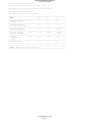
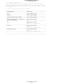
Displays receive separate red, green, and blue analog signals through the
signal cable (75 ohms impedance). Separate, non-interlaced, horizontal
and vertical synchronization signals are also received through the signal
cable.
The polarity of the synchronization signals controls the modes of
operation. Modes of operation set vertical frequencies to vary the
maximum number of lines that can be displayed. The number of lines
displayed creates screen resolution. Each display can be used in three to
six operating modes. The modes are dependent on the display and the
computer system that the display is connected to. The polarities and
operating characteristics of the four primary modes are shown in the
following table:
+------------------------------------------------------------------------+
¦
¦ Mode 1
¦ Mode 2 ¦ Mode 3
¦ Mode 4 ¦
+------------------------------+----------+---------+----------+---------¦
¦ Horizontal synchronization
¦ +
¦ -¦ -¦ +
¦
¦ signal
¦
¦
¦
¦
¦
+------------------------------+----------+---------+----------+---------¦
¦ Vertical synchronization
¦ -¦ +
¦ -¦ +
¦
¦ signal
¦
¦
¦
¦
¦
+------------------------------------------------------------------------+
Displays with only three operating modes have mode 4 reserved. Displays
with more than these four modes use interlaced horizontal and vertical
synchronization signals to create additional modes. The 8517 display has
two mode 4s available; the program providing the mode automatically
selects one of them, depending on the adapter in use.
The IBM Personal System/2 Color Displays Test-Pattern Diskette examines
the mode configuration from the monitor and the type of computer being
used and displays the modes available for the monitor.
¦ Copyright IBM Corp. 1993
1.1.1 - 1
PS/2 Displays Maintenance Manual
Operator Controls and Power-On Indicator
1.1.2 Operator Controls and Power-On Indicator
.
PICTURE 2
Figure
1-1. Example Operator Controls
All PS/2 Displays have operator controls and power-on indicators similar
to those shown in Figure 1-1. On some older displays, the controls
perform the same functions but are not located at the same places.
When the power switch is set to off, the pushbutton is level with the
surface of the control panel. Press the pushbutton 1 to switch on the
display. Press again to switch off; the pushbutton returns to its
original position.
On the older model displays, the power switch is located on the right side
of the display. Push the lever-action switch in to switch on the display.
To turn off the display, push in the opposite side of the switch.
Subtopics
1.1.2.1 Contrast Control
1.1.2.2 Brightness Control
1.1.2.3 Power-On Indicator
¦ Copyright IBM Corp. 1993
1.1.2 - 1
PS/2 Displays Maintenance Manual
Contrast Control
1.1.2.1 Contrast Control
The contrast control is on the face of the display. To increase contrast,
move the control 2 from left to right. On some older displays, the
contrast control is on the left side. To increase contrast, move the
control from back to front.
¦ Copyright IBM Corp. 1993
1.1.2.1 - 1
PS/2 Displays Maintenance Manual
Brightness Control
1.1.2.2 Brightness Control
The brightness control is on the face of the display. To increase
brightness, move the control 3 from left to right. On some older
models, the brightness control is on the left side. To increase the
brightness, move the control from back to front. All brightness controls
have a center detent position (midpoint).
¦ Copyright IBM Corp. 1993
1.1.2.2 - 1
PS/2 Displays Maintenance Manual
Power-On Indicator
1.1.2.3 Power-On Indicator
For all models, the power-on indicator (green LED) 4 lights when the
display is switched on and electrical power is present.
¦ Copyright IBM Corp. 1993
1.1.2.3 - 1
PS/2 Displays Maintenance Manual
Powering Off the System
1.1.3 Powering Off the System
CAUTION:
Before removing any part of the display:
1.
Power off the PS/2 system (including all attached devices).
2.
Power off the display, and wait for five seconds.
3.
Disconnect all power cords from power outlets and the display.
4.
Disconnect all connecting cables.
PICTURE 3
Figure
1-2. Power Off the System
¦ Copyright IBM Corp. 1993
1.1.3 - 1
PS/2 Displays Maintenance Manual
2. Diagnostic Guide
1.2 2. Diagnostic Guide
This chapter describes the procedures for basic diagnoses, function
checks, and self-tests that can be used to pinpoint problems on the
display. The basic diagnostic procedures include initial visual and power
checks; the self-test is a display-powered, on-screen pattern check.
This chapter also introduces general function checks and adjustment
procedures. Complete function checks and adjustment procedures for
individual display types are included in "Part II. Display-Specific
Service Information."
Initial checks for the 8516 Color Touch Display appear in "8516-Specific
Information" in topic 2.4. The general initial checks included here for
all other displays do not apply to the 8516 Touch Display.
DANGER
+------------------------------------------------------------------------+
¦ Areas of the analog and video card assemblies that you will be
¦
¦ removing and replacing carry high voltages. Use extreme caution when ¦
¦ carrying out the removal and replacement steps and while adjusting the ¦
¦ display when it is on.
¦
+------------------------------------------------------------------------+
CAUTION:
Use extreme caution when making adjustments with the display powered on;
these adjustments should not be performed unattended.
The display must never be left unattended with the covers removed and
powered on in a customer environment.
To prevent electrical shock, power off the display and disconnect the
power cord before you change any part.
High voltages may remain on the anode of the CRT after the display is
powered off. Discharge in accordance with CRT safety instructions. See
"High Voltage Discharge Procedure" in topic 1.3.4 for instructions on how
to discharge the CRT.
CRTs are under vacuum. All persons working near an exposed CRT must wear
safety glasses and long-sleeved clothing (or comparable protection).
Subtopics
1.2.1 Initial Checks
1.2.2 Self-Test
1.2.3 Basic Function and Pattern Checks and Adjustments
1.2.4 Degaussing
¦ Copyright IBM Corp. 1993
1.2 - 1
PS/2 Displays Maintenance Manual
Initial Checks
1.2.1 Initial Checks
The initial checks, visual and power, confirm whether or not the display
is ready for operation.
Subtopics
1.2.1.1 Visual check 0100
1.2.1.2 Power check 0110
¦ Copyright IBM Corp. 1993
1.2.1 - 1
PS/2 Displays Maintenance Manual
Visual check 0100
1.2.1.1 Visual check 0100
+---+
¦001¦
+---+
- Check the display and connectors for damage, and make sure that the
connectors are properly attached.
IS THE DISPLAY DAMAGED?
Yes No
¦
¦
¦
¦
¦
+---+
¦
¦002¦
¦
+---+
¦
¦
Go to Power check.
¦
¦
+---+
¦003¦
+---+
- Exchange the damaged parts.
Go to Power check.
--------------------------------------------------------------------------
¦ Copyright IBM Corp. 1993
1.2.1.1 - 1
PS/2 Displays Maintenance Manual
Power check 0110
1.2.1.2 Power check 0110
Note: If you change the card tray assembly or the Integrated Tube
Component (ITC), you must then check all the adjustments for the display.
+---+
¦001¦
+---+
- Remove the power cord from the power outlet, and then from the display.
- Set the power switch to on and to off several times.
DOES THE POWER SWITCH OPERATE NORMALLY?
Yes No
¦
¦
¦
¦
¦
+---+
¦
¦002¦
¦
+---+
¦
¦
Install new card tray assembly. See removal and replacement
¦
information under "Part II. Display-Specific Service Information" for
¦
the display you are servicing.
¦
¦
On 8517/9517 Displays, a new Pod Assembly must be installed. See
¦
"8517/9517-Specific Information" in topic 2.5 for Pod Assembly
¦
information.
¦
¦
+---+
¦003¦
+---+
- Set the power switch to off.
- Connect a power cord (that is known to be good) to the display and then
to the electrical power outlet.
- Set the power switch to on.
IS THE POWER LED ON?
Yes No
¦
¦
¦
¦
¦
+---+
¦
¦004¦
¦
+---+
¦
¦
Install new card tray assembly. See removal and replacement
¦
information under "Part II. Display-Specific Service Information" for
¦
the display you are servicing.
¦
¦
For 8517/9517 Displays, a Pod Assembly check must be performed (see
¦
"Pod Assembly Checks" in topic 2.5.2.3). The Pod Assembly must be
¦
replaced if it is defective. Otherwise, install a new analog card.
¦
See "8517/9517-Specific Information" in topic 2.5 for card removal
¦
and replacement information.
¦
¦
+---+
¦005¦
+---+
Continue with Self-Test.
--------------------------------------------------------------------------
¦ Copyright IBM Corp. 1993
1.2.1.2 - 1
PS/2 Displays Maintenance Manual
Self-Test
1.2.2 Self-Test
The self-test checks for a full white display screen. The white screen
will have black borders of various thickness on one or all sides depending
on which display you are servicing.
1.
Power off the display.
2.
Disconnect the signal cable.
3.
Power on the display.
Note:
The display must be powered on for five minutes before starting
the test.
4.
Set the contrast and brightness controls to maximum.
5.
The self-test pattern on the screen should be a full white raster (a
pattern of horizontal scanned lines) with a black border.
6.
If the self-test pattern does not appear correctly, go to "Basic
Function and Pattern Checks and Adjustments" in topic 1.2.3.
7.
If the self-test raster appears correctly, the video problem may be
caused by the system unit, the display signal cable, or connection.
Connect the display to another system unit to test the video problem,
then proceed to the function and pattern checks and adjustments for
the specific display you are servicing.
PICTURE 4
Figure
2-1. Typical Self-Test Pattern
Note: There are two fine transverse black lines across the screens of
8517/9517 Displays. These are part of the normal background for these
displays.
¦ Copyright IBM Corp. 1993
1.2.2 - 1
PS/2 Displays Maintenance Manual
Basic Function and Pattern Checks and Adjustments
1.2.3 Basic Function and Pattern Checks and Adjustments
Basic function and pattern checks are diagnostic procedures based on the
self-test. A series of questions about the raster image indicates the
symptom of the problem. Each symptom has an action to resolve the
problem. The actions involve adjusting certain control potentiometers on
the analog or video cards and/or replacing a part of the display.
If any components of the display require replacement, then a series of
adjustments is required to return the display to normal operation. The
IBM Personal System/2 Color Displays Test-Pattern Diskette (part number
41G8502) is used with the display and host PS/2 to help you perform the
adjustments. These adjustments reset normal color, contrast, and other
display functions.
The diagnostic procedures and actions required to return a display to
normal operation vary from display to display. Because the diagnoses and
actions are specific to each display, the detailed function and pattern
checks and adjustment procedures are included under the display type in
"Part II. Display-Specific Service Information."
¦ Copyright IBM Corp. 1993
1.2.3 - 1
PS/2 Displays Maintenance Manual
Degaussing
1.2.4 Degaussing
Throughout the display-specific service procedures, references are made to
degaussing the color display. The following material explains degaussing
and the procedures to follow for degaussing a display.
The effect of stray magnetic fields on the color purity of an Integrated
Tube Component (ITC) depends on the orientation of these fields with
respect to the ITC. Color displays have a magnetic shielding system,
consisting of a magnetic screen (internal to the ITC), and the shadow mask
(together with its mounting frame), to combat stray magnetic fields.
To be effective, the shielding system must be degaussed by applying a
strong alternating magnetic field which decays gradually and symmetrically
to zero.
This is achieved by using dual, positive temperature coefficient resistors
(PTC) in conjunction with a degauss coil on the ITC. When the mains input
voltage is applied to the display, the peak inrush current through the
coil is limited by one half of the dual PTC, while the other half is
heated by the current flow in it. Equilibrium is achieved when the heat
in one half of the PTC is sufficient to prevent current flow in the other
half, and consequently in the degauss coil.
When degaussing is required, (for example, if a display is relocated) the
heating associated with a degauss action means that another degauss action
cannot be started until the circuit has cooled down.
Allow at least 30 minutes with the display powered off, before starting
another degauss action.
¦ Copyright IBM Corp. 1993
1.2.4 - 1
PS/2 Displays Maintenance Manual
3. Removal and Replacement
1.3 3. Removal and Replacement
This chapter describes how to remove and replace parts of the PS/2
Display. The first part of the chapter covers removal and replacement
procedures for the tilt swivel stands and rear covers of the displays.
The chapter continues with instructions on how to discharge high voltages
in the displays once the rear cover is removed.
This chapter also covers general removal and replacement procedures for
the card tray assemblies, signal cables, and integrated tube components
(ITCs). Included here are references to display-specific information,
where you will find complete details on removing and replacing these
components for each individual display type.
CAUTION:
The display must never be left unattended with the covers removed and
powered on in a customer environment.
Each main part of the display has its own removal procedure, for example,
"Tilt Swivel Stand." Where a step in a specific procedure represents a
complete procedure that is described separately, a reference to that
complete procedure is given. For example:
1.
Power off the system (see "Powering Off the System" in topic 1.1.3).
2.
Remove the tilt swivel stand (see "Tilt Swivel Stand" in topic 1.3.1).
3.
Remove the rear cover (see "Rear Cover" in topic 1.3.3).
The steps show you where you can find the complete instructions for each
procedure.
To replace a part, reverse the removal procedure and observe any
additional replacement instructions.
Always ensure that parts are located correctly and latched into position
(where applicable) before securing.
After removing and replacing any field replacement units (FRUs), the
appropriate alignment procedures must be performed on the display.
Adjustment procedures are presented in "Part II. Display-Specific Service
Information" for each display type.
Subtopics
1.3.1 Tilt Swivel Stand
1.3.2 Lift Tilt Swivel Stand
1.3.3 Rear Cover
1.3.4 High Voltage Discharge Procedure
1.3.5 Card Tray Assemblies
1.3.6 Signal Cable
1.3.7 Integrated Tube Component (ITC)
1.3.8 Safety Check for Chassis Ground
¦ Copyright IBM Corp. 1993
1.3 - 1
PS/2 Displays Maintenance Manual
Tilt Swivel Stand
1.3.1 Tilt Swivel Stand
The tilt swivel stand is the same for most models, but some have a
different method of attachment and some lift as well as tilt and swivel.
1.
Power off the system and the display, and disconnect all cables.
"Powering Off the System" in topic 1.1.3.)
(See
2.
Place the display on its front cover, protected with a soft cloth or
similar material.
3.
Remove the thumbscrew 1 , disengage the locating hooks
the tilt swivel stand away from the display.
2 , and move
PICTURE 5
Figure
3-1. Removing the Tilt Swivel Stand
Other displays have a tilt swivel stand that is held on with two release
clips. For those types of stands, use these instructions after powering
off the system and removing all cables.
1.
Place the display on a flat surface, ensuring that there is sufficient
space to set the display down after removing from the stand.
2.
Press the two release clips at the front of the stand assembly.
3.
Pull the display forward from the tilt swivel stand.
4.
Lift the display from the stand and place it on a flat surface.
Replacement:
Replace the tilt swivel stand by using these instructions in reverse
order.
¦ Copyright IBM Corp. 1993
1.3.1 - 1
PS/2 Displays Maintenance Manual
Lift Tilt Swivel Stand
1.3.2 Lift Tilt Swivel Stand
The other type of stand for the PS/2 Displays is the lift tilt swivel
stand. Remove it by following these steps.
1.
Power off the system and the display, and disconnect all cables (see
1.1.3).
2.
Carefully place the display upside down on a clean surface.
3.
Remove the lift tilt swivel stand by moving the lever in the direction
of the arrow, and disengaging the latches from the base of the
display.
PICTURE 6
Figure
3-2. Removing the Lift Tilt Swivel Stand
Replacement:
Replace the lift tilt swivel stand by using these instructions in reverse
order.
¦ Copyright IBM Corp. 1993
1.3.2 - 1
PS/2 Displays Maintenance Manual
Rear Cover
1.3.3 Rear Cover
Two types of rear covers are used on the displays:
Type 1 cover removal involves removing one or more securing screws and
inserting delatching tools (IBM part number 59X6319) into slots to
release the cover.
Type 2 cover removal involves simply uncapping securing screws and
removing all screws normally to release the rear cover.
Instructions and illustrations for both types are shown below.
Subtopics
1.3.3.1 Rear Covers, Type 1
1.3.3.2 Rear Cover, Type 2
¦ Copyright IBM Corp. 1993
1.3.3 - 1
PS/2 Displays Maintenance Manual
Rear Covers, Type 1
1.3.3.1 Rear Covers, Type 1
The removal procedures for this type of rear cover are:
1.
Power off the system and the display, and disconnect all cables (see
"Powering Off the System" in topic 1.1.3).
2. Remove the tilt swivel stand (see "Tilt Swivel Stand" in topic 1.3.1),
or the lift tilt swivel stand (see "Lift Tilt Swivel Stand" in
topic 1.3.2).
3. Refer to Figure 3-3.
4. Remove the two securing screws 1 from the rear cover.
Some models have only a single hex head screw on the bottom of the display
that must be removed. Additionally, these covers may require that you
unclip two plastic closing plates from the interface cable to allow the
plug to pass through the cover.
5.
6.
Insert the delatching tools 2 into the slots to release the
fasteners.
Ease the rear cover 3 away from the display, after disengaging the
signal cable from the retention slot.
PICTURE 7
Figure
3-3. Removing the Rear Cover, Type 1
Replacement:
Ensure that the securing arms of the card tray assembly are latched into
the front cover.
¦ Copyright IBM Corp. 1993
1.3.3.1 - 1
PS/2 Displays Maintenance Manual
Rear Cover, Type 2
1.3.3.2 Rear Cover, Type 2
The removal procedures for this type of rear cover are:
1.
2.
3.
4.
5.
6.
Turn power off at the system unit and the display, and disconnect all
cables (see "Powering Off the System" in topic 1.1.3).
Remove the tilt swivel stand (see "Tilt Swivel Stand" in topic 1.3.1),
or the lift tilt swivel stand (see "Lift Tilt Swivel Stand" in
topic 1.3.2).
Refer to Figure 3-4.
Remove the covers 1 from the two securing screws 2 on the top of
the rear cover 3 .
Remove the four screws 2 from the rear cover.
Ease the rear cover away from the display.
PICTURE 8
Figure
3-4. Removing the Rear Cover, Type 2
Replacement:
Replace the rear cover using these instructions in reverse order.
¦ Copyright IBM Corp. 1993
1.3.3.2 - 1
PS/2 Displays Maintenance Manual
High Voltage Discharge Procedure
1.3.4 High Voltage Discharge Procedure
This section describes how to discharge high voltages from the exposed
components of the display.
DANGER
+------------------------------------------------------------------------+
¦
¦
¦
Hazardous voltages are present on the analog and video cards.
¦
¦
¦
¦
The extra high tension (EHT) voltage on the CRT anode cap exceeds ¦
¦
23 kV. Use extreme caution when working on the display with the
¦
¦
power on and the covers removed.
¦
¦
¦
¦
Some adjustments require you to place tools close to the EHT
¦
¦
voltage. For safety and performance reasons, only plastic or
¦
¦
insulated metal tools should be used.
¦
¦
¦
¦
Remove all jewelry before starting any repair process.
¦
¦
¦
¦
Never leave the display unattended with the covers removed. This ¦
¦
applies whether or not the power cord is connected to the power
¦
¦
outlet.
¦
¦
¦
¦
With the power cord connected, voltage may be present at the power ¦
¦
supply card even with power switched off.
¦
¦
¦
¦
A static charge may be present at the line cord connector, at the ¦
¦
rear of the display, if the line cord is disconnected before the
¦
¦
power is switched off.
¦
¦
Always turn the power on/off switch off first, then wait
¦
¦
approximately five seconds before unplugging the power cord from
¦
¦
the back of the display.
¦
¦
¦
¦
Under fault conditions, a static charge can remain on the CRT
¦
¦
anode long after the power cord has been disconnected. For this
¦
¦
reason, it is important to discharge the CRT anode before
¦
¦
disconnecting the anode lead.
¦
¦
¦
+------------------------------------------------------------------------+
To avoid any shock hazard when working in the area of the high voltage
anode lead, use the following to discharge the CRT to ground:
Screwdriver (part 1650855 or equivalent)
Jumper (part 7838690 or equivalent) with an alligator clip (part
7838688 or equivalent) attached to each end; or Meter Lead Kit (part
6428104).
Please read the complete discharge procedure before starting; then
continue in the order given.
1.
Power off the system and the display, and disconnect all cables (see
1.1.3).
2.
Remove the tilt swivel stand (see "Tilt Swivel Stand" in topic 1.3.1),
or the lift tilt swivel stand (see "Lift Tilt Swivel Stand" in
topic 1.3.2).
3.
Remove the rear cover (see 1.3.3).
4.
Refer to Figure 3-5.
5.
Connect one end of the jumper 1 to the CRT ground 2 , and the other
end to the screwdriver shaft 3 , except for models 8517 and 9517.
PICTURE 9
Figure
3-5. Connecting the Jumper for CRT Discharge
For display models 8517 and 9517, connect the jumper between the shield
around the integrated tube component and the uninsulated part of the
screwdriver shaft as shown in Figure 3-6. This will discharge the anode
of the CRT 1 to the ITC shield (ground).
PICTURE 10
Figure
3-6. CRT Discharge Connection for 8517/9517 Displays
¦ Copyright IBM Corp. 1993
1.3.4 - 1
PS/2 Displays Maintenance Manual
High Voltage Discharge Procedure
6.
Do not touch any conductive parts when discharging high voltages.
Insert the blade of the screwdriver under the suction cup until the
end touches the anode lead connector 4 .
PICTURE 11
Figure
3-7. Discharge High Voltage to CRT Ground
7.
Do this several times to ensure a complete discharge.
8.
Carefully remove the anode suction cup from the CRT.
Note:
Remove the anode suction cup immediately after discharge, to
prevent the CRT capacitance from recharging. If you are delayed
for more than a minute or two, perform the discharge procedure
again.
¦ Copyright IBM Corp. 1993
1.3.4 - 2
PS/2 Displays Maintenance Manual
Card Tray Assemblies
1.3.5 Card Tray Assemblies
Card tray assemblies include the analog and video cards, the brightness
and contrast controls, and the ac inlet connector. However, card tray
assemblies are different for most of the displays, and procedures specific
to each individual display type are presented in the related sections in
"Part II. Display-Specific Service Information."
To remove the card tray assembly:
1.
2.
3.
4.
Power off the system and the display, and disconnect all cables (see
"Powering Off the System" in topic 1.1.3).
Remove the tilt swivel stand (see "Tilt Swivel Stand" in topic 1.3.1),
or the lift tilt swivel stand (see "Lift Tilt Swivel Stand" in
topic 1.3.2).
Remove the rear cover (see "Rear Cover" in topic 1.3.3).
Refer to "Part II. Display-Specific Service Information" for detailed
instructions and illustrations for the type of display you are
servicing.
¦ Copyright IBM Corp. 1993
1.3.5 - 1
PS/2 Displays Maintenance Manual
Signal Cable
1.3.6 Signal Cable
The signal cable transmits signals to the display from the computer
processor. This cable is clamped to the card tray and must be unclamped
to clear the card tray assembly from the cable.
Several of the clamps and card trays are different, however. Procedures
for clearing the signal cable from the card tray assemblies of specific
display models are presented "Part II. Display-Specific Service
Information."
To remove the signal cable clamps:
1.
2.
3.
4.
Power off the system and the display, and disconnect all cables (see
"Powering Off the System" in topic 1.1.3).
Remove the tilt swivel stand (see "Tilt Swivel Stand" in topic 1.3.1),
or the lift tilt swivel stand (see "Lift Tilt Swivel Stand" in
topic 1.3.2).
Remove the rear cover (see "Rear Cover" in topic 1.3.3).
Refer to "Part II. Display-Specific Service Information" for detailed
instructions and illustrations for removing the cable clamps from the
type of display you are servicing.
¦ Copyright IBM Corp. 1993
1.3.6 - 1
PS/2 Displays Maintenance Manual
Integrated Tube Component (ITC)
1.3.7 Integrated Tube Component (ITC)
CAUTION:
Refer to CRT safety notices before handling CRTs.
The following instructions cover general removal procedures for ITCs,
including those displays with ITC shields.
Note: The card tray assembly and signal cables should be removed from the
display your are servicing before you proceed with removal of the ITC.
Check the removal and replacement instructions under "Part II.
Display-Specific Service Information" for the display you are servicing
before removing the ITC.
Adjustments are required for geometry, video levels and cutoff, after
replacing any ITC. Adjustment procedures for each type of display appear
in "Part II. Display-Specific Service Information."
1.
Power off the system and the display, and disconnect all cables (see
"Powering Off the System" in topic 1.1.3).
2.
Remove the tilt swivel stand (see "Tilt Swivel Stand" in topic 1.3.1),
or the lift tilt swivel stand (see "Lift Tilt Swivel Stand" in
topic 1.3.2).
3.
Remove the rear cover (see "Rear Cover" in topic 1.3.3).
For Displays without an ITC shield:
1.
2.
3.
Refer to Figure 3-8.
Remove the Torx (**) screws 1 from each corner of the bezel.
Remove the ITC 2 from the bezel.
PICTURE 12
Figure
3-8. Removing the ITC
Replacement:
1.
Carefully place the CRT against the locating ribs on the bottom and
left-hand side of the bezel (viewed from the rear of the display).
2.
Tighten all screws firmly.
For 8513 displays, make sure the DAG contact is not obscured by the
labels.
For Displays with an ITC shield:
1.
2.
3.
4.
5.
Refer to Figure 3-9.
Remove the four screws 1 from each corner of the front cover.
Remove the ITC ground lead 4 from the ITC shield.
Remove the ITC shield 2 .
Remove the ITC 3 from the front cover.
PICTURE 13
Figure
3-9. Removing the Shield and ITC
Replacement:
Ensure that the ITC is aligned correctly before tightening the securing
screws.
(**) Trademark of Textron Incorporated. For a list of
trademarks see "Notices" in topic FRONT_1.
¦ Copyright IBM Corp. 1993
1.3.7 - 1
PS/2 Displays Maintenance Manual
Safety Check for Chassis Ground
1.3.8 Safety Check for Chassis Ground
After reassembling any display, do the following safety check before
connecting the power cord.
1.
Connect a multimeter between the ground pin on the power connector and
a rear cover securing screw (chassis).
2.
Check that the resistance is no more than 0.1 ohm, after compensating
for the resistance of the meter leads.
PICTURE 14
Figure
3-10. Safety Check
¦ Copyright IBM Corp. 1993
1.3.8 - 1
PS/2 Displays Maintenance Manual
Part II. Display-Specific Service Information
2.0 Part II. Display-Specific Service Information
The following chapters contain removal and replacement information,
functional checks, adjustment procedures, specifications, and part
location illustrations for IBM Personal System/2 Displays.
Subtopics
2.1 4. 6318/8511/8518-Specific Information
2.2 5. 8513-Specific Information
2.3 6. 8515-Specific Information
2.4 7. 8516-Specific Information
2.5 8. 8517/9517-Specific Information
2.6 9. 9515-Specific Information
2.7 10. 9518-Specific Information
¦ Copyright IBM Corp. 1993
2.0 - 1
PS/2 Displays Maintenance Manual
4. 6318/8511/8518-Specific Information
2.1 4. 6318/8511/8518-Specific Information
This chapter contains display-specific service procedures and reference
information for the IBM PS/2 6318, 8511 and 8518 Displays. Included are:
Removal and replacement procedures for the:
Card-tray assembly
Signal cable
Functional checks and adjustments, including:
Function checks
Pattern checks
Adjustment procedures
Physical and functional specifications
Part location illustrations.
For information or procedures that are the same for all displays, you are
referred to the appropriate sections under "Part I. General Service
Information."
Subtopics
2.1.1 Display-Specific Removals and Replacements
2.1.2 Functional Checks and Adjustments
2.1.3 Specifications
2.1.4 Locations 6318/8511/8518 Display
¦ Copyright IBM Corp. 1993
2.1 - 1
PS/2 Displays Maintenance Manual
Display-Specific Removals and Replacements
2.1.1 Display-Specific Removals and Replacements
Subtopics
2.1.1.1 Tilt Swivel Stand
2.1.1.2 Rear Cover
2.1.1.3 Card Tray Assembly
2.1.1.4 Signal Cables
2.1.1.5 Integrated Tube Component (ITC)
¦ Copyright IBM Corp. 1993
2.1.1 - 1
PS/2 Displays Maintenance Manual
Tilt Swivel Stand
2.1.1.1 Tilt Swivel Stand
Refer to the general procedures for removing and replacing tilt swivel
stands in "Tilt Swivel Stand" in topic 1.3.1.
¦ Copyright IBM Corp. 1993
2.1.1.1 - 1
PS/2 Displays Maintenance Manual
Rear Cover
2.1.1.2 Rear Cover
Refer to the general procedures for removing and replacing the rear cover
in "Rear Cover" in topic 1.3.3.
¦ Copyright IBM Corp. 1993
2.1.1.2 - 1
PS/2 Displays Maintenance Manual
Card Tray Assembly
2.1.1.3 Card Tray Assembly
1.
Refer to Figure 4-1.
2.
Remove the anode cap
3.
Remove the two DAG braid leads
4.
Refer to Figure 4-2.
5.
Remove the two video card ground screws
6.
Release the locking lever for the video card to CRT clamp
2
from the CRT, (see 1.3.4).
1
from the card tray assembly.
1 .
6 .
CAUTION:
Take care not to damage the neck of the CRT.
Observe all safety notices for handling CRTs.
7.
Remove the video card
3
from the CRT base.
8.
Remove the connectors
card.
8
(P401 and P100) from the ITC to the analog
9.
Delatch the two securing arms (view A) with a screwdriver then pull
the card tray assembly 4 away from the front cover.
PICTURE 15
Figure
4-1. Removing the Card Tray Assembly, 6318/8511/8518 Displays
PICTURE 16
Figure
4-2. Removing the Video Card Ground Screws, 6318/8511/8518
Displays
Replacement:
Refer to Figure 4-1.
1.
Check that the CRT pins are straight, the locking lever for the CRT
retainer is raised, and the video card is aligned correctly with the
CRT base, before replacing the card and locking it in position.
2.
Replace the plastic safety shield and the video card ground screws.
3.
Ensure that the securing arms for the card tray assembly are latched
into the front cover; take care not to damage the on/off switch in
this process.
4.
Ensure that the two DAG braid leads are properly installed, and
reconnect all cables.
Note:
Adjustments are required after replacing analog and/or video cards.
¦ Copyright IBM Corp. 1993
2.1.1.3 - 1
PS/2 Displays Maintenance Manual
Signal Cables
2.1.1.4 Signal Cables
1.
Refer to Figure 4-1 in topic 2.1.1.3.
2.
Remove the connectors 5 from the signal cable to the video card and
the associated ground lead.
3.
Remove the two screws 9 and move the tab 10 to release the analog
card. Lift the card at the rear to clear the locating pin and ease it
away from the retaining lugs on the front of the card tray assembly.
4.
Remove the clamp screws at each end of the cable
lead from the braid to ground.
5.
Note how each clamp is fitted on the cable before removing the signal
cable from the retention tabs.
7 , and remove the
PICTURE 17
Figure
4-3. Signal Cable Clamps, 6318/8511/8518 Displays
Replacement:
1.
Ensure that the front clamp makes contact with the braid and the cable
sheath because it acts as a strain relief for the cable.
2.
Replace the cable in the retention tabs so that the longer section of
braid is aligned with the rear clamp. This clamp is attached to the
braid only.
¦ Copyright IBM Corp. 1993
2.1.1.4 - 1
PS/2 Displays Maintenance Manual
Integrated Tube Component (ITC)
2.1.1.5 Integrated Tube Component (ITC)
Refer to the general procedures for removing and replacing ITCs in
"Integrated Tube Component (ITC)" in topic 1.3.7.
¦ Copyright IBM Corp. 1993
2.1.1.5 - 1
PS/2 Displays Maintenance Manual
Functional Checks and Adjustments
2.1.2 Functional Checks and Adjustments
This section contains complete function and pattern checks and adjustment
procedures for the 6318, 8511 and 8518 Displays. There are two steps to
follow in the function and pattern checks, that is, to read the "Symptom"
and follow the "Action" presented in the diagnostic tables.
Subtopics
2.1.2.1 Function Checks
2.1.2.2 Pattern Checks
2.1.2.3 Adjustment Procedures
¦ Copyright IBM Corp. 1993
2.1.2 - 1
PS/2 Displays Maintenance Manual
Function Checks
2.1.2.1 Function Checks
Basic functions can be checked using the self-test raster.
Refer to "Adjustment Procedures" in topic 2.1.2.3 when adjustments are
required after replacing components.
Refer to "Display-Specific Removals and Replacements" in topic 2.1.1 for
removal and replacement procedures.
+------------------------------------------------------------------------+
¦ Symptom
¦ Action
¦
+-----------------------+------------------------------------------------¦
¦ Any problems.
¦ First, check all connections and plugs for
¦
¦
¦ continuity.
¦
+-----------------------+------------------------------------------------¦
¦ Green LED lit but
¦ Adjust G2 control clockwise until test raster ¦
¦ test raster missing. ¦ appears AGAINST background raster. If no
¦
¦
¦ raster appears, replace ITC.
¦
+-----------------------+------------------------------------------------¦
¦ Test raster is not
¦ Adjust gain controls for missing colors. If
¦
¦ white.
¦ colors reappear, reset color point of ITC.
¦
¦
¦ Otherwise replace ITC.
¦
+-----------------------+------------------------------------------------¦
¦ Background raster is ¦ Adjust cutoff controls for missing colors. If ¦
¦ not white.
¦ colors reappear, reset color point of ITC.
¦
¦
¦ Otherwise replace ITC.
¦
+-----------------------+------------------------------------------------¦
¦ Test raster scan is
¦ If partially collapsed, adjust as appropriate. ¦
¦ collapsed
¦ If fully collapsed, replace card tray
¦
¦ horizontally or
¦ assembly.
¦
¦ vertically.
¦
¦
+------------------------------------------------------------------------+
¦ Copyright IBM Corp. 1993
2.1.2.1 - 1
PS/2 Displays Maintenance Manual
Pattern Checks
2.1.2.2 Pattern Checks
These symptoms relate to operating the display with a crosshatch pattern
displayed.
Before starting any checks, ensure that all plugs and connectors are
positioned correctly and securely.
Refer to "Adjustment Procedures" in topic 2.1.2.3 when adjustments are
required.
Refer to "Display-Specific Removals and Replacements" in topic 2.1.1 for
removal and replacement procedures.
+------------------------------------------------------------------------+
¦ Symptom
¦ Action
¦
+-----------------------+------------------------------------------------¦
¦ Displayed image width ¦ Adjust RV303. If symptom persists, replace
¦
¦ is too large or too
¦ card tray assembly.
¦
¦ small.
¦
¦
+-----------------------+------------------------------------------------¦
¦ Displayed image
¦ Adjust RV400. If symptom persists, replace
¦
¦ height is too large
¦ card tray assembly.
¦
¦ or too small.
¦
¦
+-----------------------+------------------------------------------------¦
¦ Color purity of
¦ Check degauss circuit. Ensure that P100 is
¦
¦ displayed image is
¦ connected. Power off for 30 minutes. Power
¦
¦ poor.
¦ on again to check degauss action. If symptom ¦
¦
¦ persists, replace card tray assembly.
¦
¦
¦
¦
¦
¦ ITC defective. Replace ITC.
¦
+-----------------------+------------------------------------------------¦
¦ Contrast or
¦ Check connections between P400 and P802. If
¦
¦ brightness controls
¦ good, replace card tray assembly.
¦
¦ are not working.
¦
¦
+-----------------------+------------------------------------------------¦
¦ Maximum or minimum
¦ Video color point is not set. Adjust as
¦
¦ white is poor.
¦ appropriate.
¦
+-----------------------+------------------------------------------------¦
¦ East west pincushion ¦ Adjust RV302 for optimum vertical lines. If
¦
¦ correction (EWPCC) is ¦ this is not possible, replace the card tray
¦
¦ poor (vertical lines ¦ assembly.
¦
¦ are bowed or barrel
¦
¦
¦ shaped).
¦
¦
+-----------------------+------------------------------------------------¦
¦ No horizontal or
¦ If good with test raster (signal cable
¦
¦ vertical
¦ disconnected), replace signal cable.
¦
¦ synchronization.
¦
¦
¦
¦
¦
¦ One or more colors
¦
¦
¦ missing.
¦
¦
+-----------------------+------------------------------------------------¦
¦ Displayed image does ¦ Ensure that P300 is connected. If symptom
¦
¦ not synchronize
¦ persists, replace card tray assembly.
¦
¦ horizontally.
¦
¦
+-----------------------+------------------------------------------------¦
¦ Displayed image does ¦ Ensure that P300 is connected. If symptom
¦
¦ not synchronize
¦ persists, replace card tray assembly.
¦
¦ vertically.
¦
¦
+-----------------------+------------------------------------------------¦
¦ Displayed image is
¦ Adjust RV304. If image cannot be centered,
¦
¦ not centered
¦ centering circuit is faulty. Replace card
¦
¦ horizontally.
¦ tray assembly.
¦
+-----------------------+------------------------------------------------¦
¦ Displayed image
¦ Height selection circuit is faulty. Replace
¦
¦ height varies
¦ card tray assembly.
¦
¦ excessively between
¦
¦
¦ modes.
¦
¦
+-----------------------+------------------------------------------------¦
¦ Displayed image
¦ Width regulation is unstable. Ensure that
¦
¦ appears broken up
¦ P300 is connected. If symptom persists,
¦
¦ horizontally.
¦ replace card tray assembly.
¦
+------------------------------------------------------------------------+
¦ Copyright IBM Corp. 1993
2.1.2.2 - 1
PS/2 Displays Maintenance Manual
Adjustment Procedures
2.1.2.3 Adjustment Procedures
CAUTION:
Use extreme caution when making adjustments with the display powered on;
these adjustments should not be performed unattended.
The display must never be left unattended with the covers removed and
powered on in a customer environment.
Refer to "Removal and Replacement" for details of how to get access to
maintenance controls.
All adjustments must be completed in the sequence given here.
Subtopics
2.1.2.3.1
2.1.2.3.2
2.1.2.3.3
2.1.2.3.4
2.1.2.3.5
2.1.2.3.6
2.1.2.3.7
Test Equipment
Maintenance Controls and Internal Connectors
Preliminary Steps
Geometry Adjustments
Video Levels and Cutoff Voltages
Procedure Using a Color Analyzer
Focus
¦ Copyright IBM Corp. 1993
2.1.2.3 - 1
PS/2 Displays Maintenance Manual
Test Equipment
2.1.2.3.1 Test Equipment
Refer to "Tools and Test Equipment" in topic 3.3 for details of tools and
test equipment required. Ensure that the connections of all cables are
set up as shown in Figure 13-1 in topic 3.3.1.
¦ Copyright IBM Corp. 1993
2.1.2.3.1 - 1
PS/2 Displays Maintenance Manual
Maintenance Controls and Internal Connectors
2.1.2.3.2 Maintenance Controls and Internal Connectors
The following illustrations show the maintenance controls -- analog and
video card controls -- and the internal connectors of the 6318, 8511 and
8518 Displays.
PICTURE 18
Figure
4-4. Analog and Video Cards, 6318/8511/8518 Displays
PICTURE 19
Figure
4-5. Video Card, Gain and Cutoff Controls, 6318/8511/8515 Displays
¦ Copyright IBM Corp. 1993
2.1.2.3.2 - 1
PS/2 Displays Maintenance Manual
Preliminary Steps
2.1.2.3.3 Preliminary Steps
Proceed as follows.
1.
Insert the IBM PS/2 Color Displays Test-Pattern Diskette into drive A
of the system unit.
CAUTION:
Use caution when making adjustments with the cover removed.
high voltages on the analog and video cards.
There are
2.
Power on the system unit and the display. The system unit runs its
internal checks, and then loads the program from the diskette.
3.
With the Brightness control set to center detent (midpoint), adjust G2
and Focus until the setup menu is visible. Select pattern C and
adjust the G2 control to give minimum background illumination.
4.
Allow 20 minutes for the display to warm up before making any further
adjustments.
5.
Set the Contrast control to midpoint.
Note: On 6318 Displays center the four POTS on the Operator Control Card
prior to performing the Geometry Adjustments.
¦ Copyright IBM Corp. 1993
2.1.2.3.3 - 1
PS/2 Displays Maintenance Manual
Geometry Adjustments
2.1.2.3.4 Geometry Adjustments
Proceed as follows.
1.
Select pattern A, the cross-hatch pattern on a black background:
a.
Adjust RV304 (Raster Centering) to center the rectangle.
b.
Adjust RV303 (Width) for a gap of:
16 mm (for 6318, 8511 Color Displays),
11 mm (for 8518 Color Displays),
(measured at the horizontal center line of the screen) between the
vertical edges of the green rectangle and the inner edges of the
bezel.
2.
c.
Adjust RV302 (East West Pincushion) to set the straightest
possible vertical lines.
d.
You may have to repeat steps a, b, and c.
Using the same test pattern, adjust sequentially RV400 (Vertical
Height) and RV401 (Vertical Centering). Set the picture in the center
of the screen with a gap of:
11 mm (for 6318, 8511 Color Displays),
7.5 mm (for 8518 Color Displays),
(measured at the vertical center line of the screen) between the
horizontal edges of the green rectangle and the inner edges of the top
and bottom of the bezel.
¦ Copyright IBM Corp. 1993
2.1.2.3.4 - 1
PS/2 Displays Maintenance Manual
Video Levels and Cutoff Voltages
2.1.2.3.5 Video Levels and Cutoff Voltages
Proceed as follows.
1.
Select pattern C, the full screen raster and press the spacebar four
times for a black field:
a.
Set RV600, RV631, RV651, and RV671 (cutoff potentiometers) fully
clockwise, as viewed from the video card shield.
b.
Set RV632 and RV652 (gain potentiometers) fully clockwise, as
viewed from the top of the video card.
c.
Set the Brightness control to center detent (midpoint), and the
Contrast control to midpoint.
d.
Adjust G2 so that the screen is just not illuminated.
Brightness control to maximum.
e.
Adjust the cutoff potentiometers for a correct white color point.
f.
Set the Brightness control to center detent (midpoint). If
necessary, adjust G2 to ensure that the screen is just not
illuminated.
Set the
2.
Select Pattern B, 50 mm square box and press the spacebar three times
for a white box.
3.
Ensure that the Contrast control is at midpoint.
4.
Adjust RV652 (green) and RV632 (red) for correct white color points.
5.
Set Contrast to maximum.
6.
Set RV600 to midpoint.
7.
Select pattern D, gray scale blocks.
8.
Check, at maximum and minimum contrast, that the gradation of the
blocks is even from black through white with no color tinges.
9.
Check that there is no color smearing.
If steps 8 and 9 are not satisfactory, repeat this complete procedure.
Note:
The use of a color analyzer is recommended for steps 1e, 4, and 6.
¦ Copyright IBM Corp. 1993
2.1.2.3.5 - 1
PS/2 Displays Maintenance Manual
Procedure Using a Color Analyzer
2.1.2.3.6 Procedure Using a Color Analyzer
The use of a Minolta TV Color Analyzer (**), or equivalent, is recommended
for setting the white color point and maximum brightness.
1.
Select pattern C, full-screen raster and depress the spacebar four
times for a black field:
a.
Set RV600, RV631, RV651, and RV671 (cutoff potentiometers) fully
clockwise, as viewed from the video card shield.
b.
Set RV632 and RV652 (gain potentiometers) fully clockwise, as
viewed from the top of the video card.
c.
Set the Brightness control to center detent (midpoint), and the
Contrast control to midpoint.
d.
Adjust G2 so that the screen is just not illuminated.
Brightness control to maximum.
e.
Adjust the cutoff potentiometers for a correct white color point.
Using a Minolta Color Analyzer, or equivalent, in accordance with
the manufacturer's instructions, this is:
x=0.267 ± 0.01, y=0.282 ± 0.01.
f.
Set the Brightness control to center detent (midpoint). If
necessary, adjust G2 to ensure that the screen is just not
illuminated.
Set the
2.
Select Pattern B, 50 mm square box and press the spacebar three times
for a white box.
3.
Ensure that the Contrast control is at midpoint.
4.
Adjust RV652 (green) and RV632 (red) for correct white color points.
Using a Minolta Color Analyzer, or equivalent, in accordance with the
manufacturer's instructions, this is:
x=0.297 ± 0.01, y=0.320 ± 0.01.
5.
Set Contrast to maximum.
6.
Set RV600 using the color analyzer, to give 200 nits ± 5 nits (cd/m²)
in the white block.
7.
Select pattern D, gray scale blocks.
8.
Check, at maximum and minimum contrast, that the gradation of the
blocks is even from black through white with no color tinges.
9.
Check that there is no color smearing.
If steps 8 and 9 are not satisfactory, repeat this complete procedure.
(**) Trademark of the Minolta Corporation. For a list of
trademarks see "Notices" in topic FRONT_1.
¦ Copyright IBM Corp. 1993
2.1.2.3.6 - 1
PS/2 Displays Maintenance Manual
Focus
2.1.2.3.7 Focus
Proceed as follows.
1.
2.
Select pattern E, Focus.
Adjust the Focus control to give sharp vertical and horizontal lines.
Take care not to disturb the G2 setting.
This completes the alignment procedures.
¦ Copyright IBM Corp. 1993
2.1.2.3.7 - 1
PS/2 Displays Maintenance Manual
Specifications
2.1.3 Specifications
Subtopics
2.1.3.1 Physical Characteristics
2.1.3.2 Functional Characteristics
¦ Copyright IBM Corp. 1993
2.1.3 - 1
PS/2 Displays Maintenance Manual
Physical Characteristics
2.1.3.1 Physical Characteristics
The following information applies to all models of the 6318, 8511 and 8518
Displays:
Subtopics
2.1.3.1.1
2.1.3.1.2
2.1.3.1.3
2.1.3.1.4
2.1.3.1.5
Size
Weight
Environment
Power Output
Electrical
¦ Copyright IBM Corp. 1993
2.1.3.1 - 1
PS/2 Displays Maintenance Manual
Size
2.1.3.1.1 Size
Height 310 mm (12.2 in.), excluding stand
Width 355 mm (14 in.)
Depth 390 mm (15.3 in.).
¦ Copyright IBM Corp. 1993
2.1.3.1.1 - 1
PS/2 Displays Maintenance Manual
Weight
2.1.3.1.2 Weight
12.5 kg (27.5 lb), excluding stand.
¦ Copyright IBM Corp. 1993
2.1.3.1.2 - 1
PS/2 Displays Maintenance Manual
Environment
2.1.3.1.3 Environment
Temperature:
- Operating
10° to 35°C (50 to 95°F)
- Storage
1° to 60°C (33 to 140°F)
- Shipping
-20° to 60°C (-4 to 140°F).
Humidity:
- Operating
8% to 80%
- Storage
5% to 80%
- Shipping
5% to 100%
Note:
The higher levels of humidity for shipping allow for
condensation, but not direct contact with moisture.
Maximum Altitude 2000 m (6565 ft).
¦ Copyright IBM Corp. 1993
2.1.3.1.3 - 1
PS/2 Displays Maintenance Manual
Power Output
2.1.3.1.4 Power Output
75 watts maximum
¦ Copyright IBM Corp. 1993
2.1.3.1.4 - 1
PS/2 Displays Maintenance Manual
Electrical
2.1.3.1.5 Electrical
Model
Model
Model
Model
Model
Model
6318001: 90 to 137 V ac, 47 to 63 Hz
8511001 and 8518001: 90 to 137 V ac, 47
8511002 and 8518002: 90 to 265 V ac, 47
8511003 and 8518003: 90 to 265 V ac, 47
8511004 and 8518004: 90 to 265 V ac, 47
8518022: 180 to 265 V ac, 47 to 63 Hz
to
to
to
to
63
63
63
63
Hz
Hz
Hz
Hz
¦ Copyright IBM Corp. 1993
2.1.3.1.5 - 1
PS/2 Displays Maintenance Manual
Functional Characteristics
2.1.3.2 Functional Characteristics
Video input: analog, direct-drive, 75 ohm, 0 to 0.7 V.
6318/8511 CRT faceplate: antiglare (etched or silica coated).
8518 CRT faceplate: dark, antiglare (etched or silica coated).
CRT phosphor: short persistence (P22).
+------------------------------------------------------------------------+
¦ MODE
¦ 1
¦ 2
¦ 3
¦
+----------------------------+--------------+--------------+-------------¦
¦ Horizontal deflection rate ¦ 31.5
¦ 31.5
¦ 31.5
¦
¦ (kilohertz)
¦
¦
¦
¦
+----------------------------+--------------+--------------+-------------¦
¦ Vertical deflection rate
¦ 70
¦ 70
¦ 60
¦
¦ (frames per sec)
¦
¦
¦
¦
+----------------------------+--------------+--------------+-------------¦
¦ Horizontal blanking time
¦ 5.72
¦ 5.72
¦ 5.72
¦
¦ (microseconds)
¦
¦
¦
¦
+----------------------------+--------------+--------------+-------------¦
¦ Vertical blanking time
¦ 2.76
¦ 1.12
¦ 0.92
¦
¦ (milliseconds)
¦
¦
¦
¦
+----------------------------+--------------+--------------+-------------¦
¦ Vertical addressability
¦ 362
¦ 414
¦ 496
¦
¦ (lines)
¦
¦
¦
¦
+----------------------------+--------------+--------------+-------------¦
¦ Interlace ratio
¦ 1:1
¦ 1:1
¦ 1:1
¦
+----------------------------+--------------+--------------+-------------¦
¦
¦
¦
¦
¦
+------------------------------------------------------------------------+
Resolution:
Mode 1, 720 x 350 Pels, 70 Hz, non interlaced.
Mode 2, 720 x 400 Pels, 70 Hz, non interlaced.
Mode 3, 720 x 480 Pels, 60 Hz, non interlaced.
The 6318 display can also support the following modes::
Mode 4,
640 x 480 Pels, 72 Hz, non interlaced.
Mode 5,
800 x 600 Pels, 56 Hz, non interlaced.
Mode 6,
800 x 600 Pels, 60 Hz, non interlaced.
Mode 7, 1024 x 768 Pels, 87 Hz, non interlaced.
¦ Copyright IBM Corp. 1993
2.1.3.2 - 1
PS/2 Displays Maintenance Manual
Locations 6318/8511/8518 Display
2.1.4 Locations 6318/8511/8518 Display
Subtopics
2.1.4.1 Safety Grounds
2.1.4.2 Parts Locations
¦ Copyright IBM Corp. 1993
2.1.4 - 1
PS/2 Displays Maintenance Manual
Safety Grounds
2.1.4.1 Safety Grounds
PICTURE 20
Figure
4-6. Safety Grounds, 6318/8511/8518 Displays
¦ Copyright IBM Corp. 1993
2.1.4.1 - 1
PS/2 Displays Maintenance Manual
Parts Locations
2.1.4.2 Parts Locations
PICTURE 21
Figure
4-7. Parts Locations, 6318/8511/8518 Displays
¦ Copyright IBM Corp. 1993
2.1.4.2 - 1
PS/2 Displays Maintenance Manual
5. 8513-Specific Information
2.2 5. 8513-Specific Information
This chapter contains display-specific service procedures and reference
information for the 8513 Color Display. Included are:
Removal and replacement procedures for the card-tray assembly
Functional checks and adjustments, including:
Function checks
Pattern checks
Adjustment procedures
Physical and functional specifications
Part location illustrations.
For information or procedures that are generic for all displays you are
referred to the appropriate sections under "Part I. General Service
Information."
Note: This service information supports only 8513 Displays with serial
numbers beginning with "23" or "55". All other 8513 monitors must be
serviced by element exchange. See "Element Exchange Monitors" for a
complete list of the 8513 Element Exchange displays.
Subtopics
2.2.1 Display-Specific Removals and Replacements
2.2.2 Functional Checks and Adjustments
2.2.3 Specifications
2.2.4 Locations
¦ Copyright IBM Corp. 1993
2.2 - 1
PS/2 Displays Maintenance Manual
Display-Specific Removals and Replacements
2.2.1 Display-Specific Removals and Replacements
Subtopics
2.2.1.1 Tilt Swivel Stand
2.2.1.2 Rear Cover
2.2.1.3 Control Bridge Assembly
2.2.1.4 Card Tray Assembly
2.2.1.5 Integrated Tube Component (ITC)
¦ Copyright IBM Corp. 1993
2.2.1 - 1
PS/2 Displays Maintenance Manual
Tilt Swivel Stand
2.2.1.1 Tilt Swivel Stand
Refer to the general procedures for removing and replacing tilt swivel
stands in "Tilt Swivel Stand" in topic 1.3.1.
¦ Copyright IBM Corp. 1993
2.2.1.1 - 1
PS/2 Displays Maintenance Manual
Rear Cover
2.2.1.2 Rear Cover
Refer to the general procedures for removing and replacing the rear cover
in "Rear Cover" in topic 1.3.3.
¦ Copyright IBM Corp. 1993
2.2.1.2 - 1
PS/2 Displays Maintenance Manual
Control Bridge Assembly
2.2.1.3 Control Bridge Assembly
To complete the general removal procedures for the model 8513 display, you
will need to follow these instructions to remove the control bridge
assembly.
1.
Refer to Figure 5-1.
2.
Unclip and remove the user controls from the control bridge, as shown
in View A.
3.
Remove the On/Off switch by pushing down the tab and withdrawing the
switch downward, as shown in View B.
4.
Disengage the two latches, and pull the Control Bridge assembly away
from the front bezel.
PICTURE 22
Figure
5-1. Control Bridge Assembly, 8513 Display
Replacement:
Replace the Control Bridge Assembly using the above instructions in
reverse order.
¦ Copyright IBM Corp. 1993
2.2.1.3 - 1
PS/2 Displays Maintenance Manual
Card Tray Assembly
2.2.1.4 Card Tray Assembly
1.
Refer to Figure 5-2.
2.
Remove the anode cap
3.
Remove the DAG connectors
socket.
4.
Metal Card Tray Versions only: Remove the short DAG ground leads from
the metal card tray.
5.
Unplug the scan connector
6.
Unplug the degauss connector
7.
Place the display front downward on a table and lift the main card
assembly away.
1 .
2
from the video card and the mains
3 .
4 .
PICTURE 23
Figure
5-2. Card Tray Assembly, 8513 Display
Replacement:
Replace the Card Tray Assembly using the above instructions in reverse
order.
¦ Copyright IBM Corp. 1993
2.2.1.4 - 1
PS/2 Displays Maintenance Manual
Integrated Tube Component (ITC)
2.2.1.5 Integrated Tube Component (ITC)
Refer to the general procedures for removing and replacing ITCs in
"Integrated Tube Component (ITC)" in topic 1.3.7.
¦ Copyright IBM Corp. 1993
2.2.1.5 - 1
PS/2 Displays Maintenance Manual
Functional Checks and Adjustments
2.2.2 Functional Checks and Adjustments
This section contains complete function and pattern checks and adjustment
procedures for the 8513 Display. There are two steps to follow in the
function and pattern checks, that is, to read the "Symptom" and follow the
"Action" presented in the diagnostic tables.
Subtopics
2.2.2.1 Function Checks
2.2.2.2 Pattern Checks
2.2.2.3 Adjustment Procedures
¦ Copyright IBM Corp. 1993
2.2.2 - 1
PS/2 Displays Maintenance Manual
Function Checks
2.2.2.1 Function Checks
Basic functions can be checked using the self-test raster.
Refer to "Adjustment Procedures" in topic 2.2.2.3 when adjustments are
required after replacing components.
Refer to "Display-Specific Removals and Replacements" in topic 2.2.1 for
removal and replacement procedures.
+------------------------------------------------------------------------+
¦ Symptom
¦ Action
¦
+-----------------------+------------------------------------------------¦
¦ Any problems.
¦ First, check all connections and associated
¦
¦
¦ items for continuity.
¦
+-----------------------+------------------------------------------------¦
¦ Raster missing and
¦ Replace card assembly.
¦
¦ green LED not lit.
¦
¦
+-----------------------+------------------------------------------------¦
¦ Raster missing, but
¦ Replace card assembly.
¦
¦ green LED flashes
¦
¦
¦ during attempt to
¦
¦
¦ power on.
¦
¦
+-----------------------+------------------------------------------------¦
¦ Raster missing, but
¦ Check if CRT heater is glowing:
¦
¦ green LED lit.
¦
¦
¦
¦
NO - Replace card assembly. If fault
¦
¦
¦
persists, replace the CRT.
¦
¦
¦
¦
¦
¦
YES - Turn G2 potentiometer clockwise. If ¦
¦
¦
a raster appears, readjust the video gain ¦
¦
¦
and cut-off potentiometer if possible.
¦
¦
¦
Otherwise, replace the card assembly. If ¦
¦
¦
no raster appears, replace the CRT.
¦
+-----------------------+------------------------------------------------¦
¦ Raster visible but
¦ Turn cutoff or gain controls, for the missing ¦
¦ one or two colors
¦ color(s), clockwise. If the color(s)
¦
¦ missing.
¦ reappear, readjust the video gain and cut-off ¦
¦
¦ potentiometer if possible; otherwise, replace ¦
¦
¦ the card assembly. If the colors do not
¦
¦
¦ appear, replace the CRT.
¦
+-----------------------+------------------------------------------------¦
¦ Raster visible but is ¦ Replace card assembly.
¦
¦ too narrow, or does
¦
¦
¦ not fill the bezel
¦
¦
¦ vertically.
¦
¦
+------------------------------------------------------------------------+
If the raster is the correct size, then additional checks should be
carried out. Connect the display to the PS/2 system unit, and load the
Alignment Diskette as described in "Adjustment Procedures" in
topic 2.2.2.3.
¦ Copyright IBM Corp. 1993
2.2.2.1 - 1
PS/2 Displays Maintenance Manual
Pattern Checks
2.2.2.2 Pattern Checks
Select the required pattern to suit the adjustment.
Before starting any checks, ensure that all plugs and connectors are
positioned correctly and securely.
Refer to "Adjustment Procedures" in topic 2.2.2.3 when adjustments are
required.
Refer to "Display-Specific Removals and Replacements" in topic 2.2.1 for
removal and replacement procedures.
+------------------------------------------------------------------------+
¦ Symptom
¦ Action
¦
+-----------------------+------------------------------------------------¦
¦ No E-W pincushion
¦ Turn RV201 to check whether readjustment is
¦
¦ correction.
¦ possible; otherwise, replace card assembly.
¦
+-----------------------+------------------------------------------------¦
¦ Data not centered
¦ Turn RV200 H.PHASE to check whether
¦
¦ horizontally.
¦ readjustment is possible; otherwise, replace
¦
¦
¦ the card assembly.
¦
¦
¦ Note: On units with a metal card tray, first
¦
¦
¦ adjust RV203 to center the background raster, ¦
¦
¦ then RV200. If the fault persists, replace
¦
¦
¦ the CRT.
¦
+-----------------------+------------------------------------------------¦
¦ Data will not sync
¦ Replace the interface cable. If the fault
¦
¦ horizontally.
¦ persists, replace the card assembly.
¦
+-----------------------+------------------------------------------------¦
¦ Data has insufficient ¦ Turn RV202 WIDTH to check whether readjustment ¦
¦ width.
¦ is possible; otherwise replace the card
¦
¦
¦ assembly.
¦
+-----------------------+------------------------------------------------¦
¦ Data will not sync
¦ Replace the interface cable. If the fault
¦
¦ vertically.
¦ persists, replace the card assembly.
¦
+-----------------------+------------------------------------------------¦
¦ Data has insufficient ¦ Turn RV300 HEIGHT to check whether
¦
¦ height.
¦ readjustment is possible; otherwise replace
¦
¦
¦ the card assembly.
¦
+-----------------------+------------------------------------------------¦
¦ Data does not center ¦ Turn RV301 V.CENT to check whether
¦
¦ vertically.
¦ readjustment is possible; otherwise, replace
¦
¦
¦ the card assembly. If the fault persists,
¦
¦
¦ replace the CRT.
¦
+-----------------------+------------------------------------------------¦
¦ Vertical linearity
¦ Turn RV302 V.LIN to check whether readjustment ¦
¦ poor.
¦ is possible; otherwise, replace the card
¦
¦
¦ assembly.
¦
+-----------------------+------------------------------------------------¦
¦ Horizontal linearity ¦ Replace the card assembly.
¦
¦ poor.
¦
¦
+-----------------------+------------------------------------------------¦
¦ Color(s) missing.
¦ Replace the interface cable. If the fault
¦
¦
¦ still persists, replace the card assembly. If ¦
¦
¦ the fault still persists, exchange the CRT.
¦
+-----------------------+------------------------------------------------¦
¦ Maximum white point
¦ Make sure the brightness control is in the
¦
¦ is poor.
¦ center detent position. Readjust RV700
¦
¦
¦ G.GAIN, RV701 R.GAIN, and RV702 B.GAIN to
¦
¦
¦ determine whether the correct white color can ¦
¦
¦ be obtained; otherwise, replace the card
¦
¦
¦ assembly.
¦
+-----------------------+------------------------------------------------¦
¦ Minimum white point
¦ Make sure the brightness control is in the
¦
¦ is poor.
¦ center detent position. Readjust RV800
¦
¦
¦ G.CUT-OFF, RV801 R.CUT-OFF, and RV802
¦
¦
¦ B.CUT-OFF to determine whether the correct
¦
¦
¦ white color can be obtained; otherwise,
¦
¦
¦ replace the card assembly.
¦
+-----------------------+------------------------------------------------¦
¦ Convergence poor.
¦ Replace the CRT.
¦
+-----------------------+------------------------------------------------¦
¦ Focus poor.
¦ Turn the focus potentiometer to determine if
¦
¦
¦ readjustment is possible;, if not, replace the ¦
¦
¦ card assembly. If the fault persists, replace ¦
¦
¦ the CRT.
¦
+-----------------------+------------------------------------------------¦
¦ Colors change or
¦ Install a new signal interface cable, then
¦
¦ flicker
¦ proceed as for 'Color(s) missing' above.
¦
+------------------------------------------------------------------------+
Note: To meet required safety standards, repair of the main PCB assembly
and video card assembly is not recommended.
¦ Copyright IBM Corp. 1993
2.2.2.2 - 1
PS/2 Displays Maintenance Manual
Adjustment Procedures
2.2.2.3 Adjustment Procedures
CAUTION:
Use extreme caution when making adjustments with the display powered on;
these adjustments should not be performed unattended.
The display must never be left unattended with the covers removed and
powered on in a customer environment.
Refer to "Display-Specific Removals and Replacements" in topic 2.2.1 for
details of how to get access to maintenance controls.
All adjustments must be completed in the sequence given here.
Subtopics
2.2.2.3.1
2.2.2.3.2
2.2.2.3.3
2.2.2.3.4
2.2.2.3.5
2.2.2.3.6
2.2.2.3.7
Test Equipment
Maintenance Controls and Internal Connectors
Preliminary Set-Up
Geometry Adjustments
Color Point Adjustments
Focus Adjustment
Adjustment Procedure Using Color Analyzer
¦ Copyright IBM Corp. 1993
2.2.2.3 - 1
PS/2 Displays Maintenance Manual
Test Equipment
2.2.2.3.1 Test Equipment
Refer to "Tools and Test Equipment" in topic 3.3 for details of tools and
test equipment required. Ensure that the connections of all cables are
set up as shown in Figure 13-1 in topic 3.3.1.
¦ Copyright IBM Corp. 1993
2.2.2.3.1 - 1
PS/2 Displays Maintenance Manual
Maintenance Controls and Internal Connectors
2.2.2.3.2 Maintenance Controls and Internal Connectors
The following illustrations show the maintenance controls -- the analog
and video card controls -- and the internal connectors of the 8513
Display.
PICTURE 24
Figure
5-3. Potentiometers, 8513 Display
PICTURE 25
Figure
5-4. Internal Connectors, 8513 Display
¦ Copyright IBM Corp. 1993
2.2.2.3.2 - 1
PS/2 Displays Maintenance Manual
Preliminary Set-Up
2.2.2.3.3 Preliminary Set-Up
Proceed as follows.
1.
Insert the IBM Personal System/2 Color Displays Test-Pattern Diskette
in drive A of the system unit.
CAUTION:
Use caution when making adjustments with the cover removed. There are
high voltages on the Yoke, analog, and video cards.
2.
Check to make sure that the G2 potentiometer is turned fully counter
clockwise (CCW).
3.
Power on the system unit and the 8513 Display. The system unit runs
internal checks, and then loads the program from the diskette.
4.
With the Brightness control set to the center detent position
(midpoint), adjust G2 and focus until the setup menu or an
informational prompt is visible on the screen. From the setup menu
select pattern C and adjust G2 to give minimum background
illumination.
5.
Allow 20 minutes for the display to warm up before making any further
adjustments.
6.
Set the contract control to midpoint.
¦ Copyright IBM Corp. 1993
2.2.2.3.3 - 1
PS/2 Displays Maintenance Manual
Geometry Adjustments
2.2.2.3.4 Geometry Adjustments
Proceed as follows.
1.
Select pattern B, 50 mm Square Box on a black background:
Note:
Before doing this step, if you are servicing a display
with a metal card tray, adjust RV203 (Raster Center) first to
centralize the raster in the bezel. You may have to turn
Brightness control CCW to see raster.
Adjust RV200 (H.Phase) potentiometer to centralize the rectangle
horizontally on the screen.
2.
a.
Adjust RV202 (Width) for a gap of 14 mm (measured at the
horizontal center line of the screen) between the vertical green
edges of the rectangle and the inner edges of the bezel.
b.
Adjust RV201 (East West Pincushion) to set the straightest
possible vertical lines.
c.
Press the F3 function key, then select pattern A (Crosshatch).
Adjust the RV302 (V. Lin.) potentiometer to get squares of equal
height.
d.
You may have to repeat steps a, b, c, and d.
Press the F3 function key, then select pattern B (50 mm Square Box),
adjust sequentially RV300 (Vertical Height) and RV301 (Vertical
Centering). Set the picture in the center of the screen with a gap of
8 mm (measured at the vertical center line of the screen) between the
horizontal edges of the green rectangle and the inner edges of the top
and bottom of the bezel.
¦ Copyright IBM Corp. 1993
2.2.2.3.4 - 1
PS/2 Displays Maintenance Manual
Color Point Adjustments
2.2.2.3.5 Color Point Adjustments
Proceed as follows.
1.
Insert the Color Displays Test-Pattern Diskette in drive A of system
unit.
CAUTION:
Use caution when making adjustments with the cover removed. There are
high voltages on the Yoke, analog and video cards.
2.
Power on the system unit and the 8513 Display. The system unit runs
internal checks, and then loads the program from the diskette.
3.
Turn all color pots RV700, RV800, RV701, RV801, RV702, and RV802 on
the ITC card (on the back of the tube) full CCW.
4.
With the Brightness control set to center detent (midpoint) and
Contrast control to midpoint: Adjust G2 (intensity pot), lower pot on
HVT, until the MSG. and A: prompt are visible. Adjust FOCUS, upper pot
on HVT for clarity. Type "VGA" at the A: prompt and press Enter.
Press Enter 720 x 350 screen. Select pattern C (Full Screen Raster),
then press Enter four times for a BLACK field. Turn G2 CCW until the
screen just goes blank.
5.
Allow 20 minutes for the display to warm up before making any further
adjustments.
6.
Set the Brightness and Contrast control to maximum CCW, looking from
the top of the display.
7.
Adjust the cutoff potentiometers RV800 (Green Cut-Off), RV801 (Red
Cut-Off), RV802 (Blue Cut-Off), for a correct white color point.
Note:
Adjust the predominant color on the screen last if needed.
8.
Set the Brightness control to center detent (midpoint). If screen is
illuminated, adjust G2 to ensure the screen is just not illuminated.
9.
Depress F3, select pattern A (Crosshatch) on the setup diskette. This
will display the GREEN crosshatch.
10. Set the Brightness and Contrast controls (minimum) fully CW, as viewed
from the top of the display. Then Adjust RV700 (GREEN Gain) CW until
the crosshatch illuminates GREEN then CCW until the vertical lines
just go blank.
11. Depress the Enter key once to display the BLUE crosshatch. Then adjust
RV702 (BLUE Gain) CW until the crosshatch illuminates BLUE, then CCW
until the vertical lines just go blank.
12. Depress the Enter key once to display the RED crosshatch. Then adjust
RV701 (RED Gain) CW until the crosshatch illuminates RED then CCW
until the vertical lines just go blank.
13. Set the Brightness control to center detent (midpoint) and Contrast
control to midpoint.
14. Depress F3, select pattern C (Full Screen Raster), press Enter three
(3) times to display the WHITE screen raster.
15. Adjust if necessary RV700 (Green Gain), RV701 (Red Gain), RV702 (Blue
Gain), for correct white color point.
Note:
Adjust the predominant color on the screen last if needed.
16. Depress F3, select pattern D (Gray Scale).
17. Check, at maximum and minimum Contrast, that the blocks are evenly
graduated from black through white with no color tinges.
18. Check that there is no color smearing.
If steps 17 and 18 are not satisfactory, repeat this complete procedure.
¦ Copyright IBM Corp. 1993
2.2.2.3.5 - 1
PS/2 Displays Maintenance Manual
Focus Adjustment
2.2.2.3.6 Focus Adjustment
Proceed as follows.
1.
Select pattern E, Focus pattern.
2.
Adjust the Focus (upper pot on the HVT) for sharp vertical and
horizontal lines. Take care not to disturb the G2 setting.
¦ Copyright IBM Corp. 1993
2.2.2.3.6 - 1
PS/2 Displays Maintenance Manual
Adjustment Procedure Using Color Analyzer
2.2.2.3.7 Adjustment Procedure Using Color Analyzer
The following instructions are included for those cases when adjustment by
eye is not successful.
1.
Insert the Color Displays Test-Pattern Diskette in drive A of system
unit.
CAUTION:
Use extreme caution when making adjustments with the cover removed.
There are high voltages on the yoke, analog and video cards.
2.
Power on the system unit and the 8513 Display. The system unit runs
internal checks, and then loads the program from the diskette.
3.
Turn RV800 Green cut off, RV801 red cut off, RV802 blue cut off, on
the ITC card ( on the back of the tube ) fully clockwise (CW).
4.
Set the Brightness and Contrast control to maximum CCW, as looking
from the top of the display.
5.
Select Pattern C (Full Screen Raster) and press the spacebar four
times for a BLACK field/raster.
6.
Turn the G2 potentiometer on the EHT transformer slowly CW until the
first color appears. Turn the associated cutoff potentiometer fully
CW.
7.
Continue turning the G2 potentiometer CW until the second color
appears. Turn the associated cutoff potentiometer fully CW also.
8.
Continue turning the G2 potentiometer CW until the third color
appears.
9.
Readjust the first and second cutoff potentiometers and G2 to get the
following white luminance and chromaticity:
(line 1 are CIE COORDINATES)
cd/m 2
x
2+1.0/-0
.0245+/-).010
y
0.263+/-0.010
a.
Green cutoff potentiometer (RV800) CW predominantly increases y.
b.
Red cutoff potentiometer (RV801) CW predominantly increases x.
c.
Blue cutoff potentiometer (RV802) CW predominantly decreases both
x and y.
10. Set the Brightness control to center detent (midpoint). Adjust RV700
(GREEN Gain), RV701 (RED Gain), RV702 (BLUE Gain) to the mid position.
11. Select pattern E, Focus pattern. Adjust the Focus (upper pot on the
HVT) for sharp vertical and horizontal lines. Take care not to
disturb the G2 setting.
12. Select pattern C (Full Screen Raster), press Enter three times to
display the WHITE screen raster. Adjust RV700 (GREEN Gain), RV701 (RED
Gain), RV702 (BLUE Gain) only to set the center screen luminance and
chromaticity to:
(line 1 are CIE COORDINATES)
cd/m 2
x
120 to 150 0.313+/-0.010
y
0.239+/-0.010
a.
Green gain potentiometer (RV700) CW predominantly increases y.
b.
Red gain potentiometer (RV701) CW predominantly increases x.
c.
Blue gain potentiometer (RV702) CW predominantly decreases both x
and y.
d.
CW rotation of all gain potentiometers increases y (brightness).
¦ Copyright IBM Corp. 1993
2.2.2.3.7 - 1
PS/2 Displays Maintenance Manual
Specifications
2.2.3 Specifications
Subtopics
2.2.3.1 Physical Characteristics
2.2.3.2 Functional Characteristics
¦ Copyright IBM Corp. 1993
2.2.3 - 1
PS/2 Displays Maintenance Manual
Physical Characteristics
2.2.3.1 Physical Characteristics
The following information applies to all models of the 8513 Display:
Subtopics
2.2.3.1.1 Weight
2.2.3.1.2 Environment
2.2.3.1.3 Electrical
¦ Copyright IBM Corp. 1993
2.2.3.1 - 1
PS/2 Displays Maintenance Manual
Weight
2.2.3.1.1 Weight
12.0 kg (26.4 lb), excluding stand.
¦ Copyright IBM Corp. 1993
2.2.3.1.1 - 1
PS/2 Displays Maintenance Manual
Environment
2.2.3.1.2 Environment
Operating Temperature: - 15° to 33°C
¦ Copyright IBM Corp. 1993
2.2.3.1.2 - 1
PS/2 Displays Maintenance Manual
Electrical
2.2.3.1.3 Electrical
Model
Model
Model
Model
8513001:
8513002:
8513003:
8513102:
90 to 137 V ac
180 to 264 V ac
180 to 264 V ac
180 to 264 V ac
¦ Copyright IBM Corp. 1993
2.2.3.1.3 - 1
PS/2 Displays Maintenance Manual
Functional Characteristics
2.2.3.2 Functional Characteristics
Video input: analog, direct-drive, 75 ohm, 0 to 0.7 V.
CRT faceplate: dark, non-reflective (etched).
CRT phosphor: short persistence (P22).
+------------------------------------------------------------------------+
¦ Horizontal deflection rate (kilohertz)
¦ 31.5
¦
+------------------------------------------------+-----------------------¦
¦ Vertical deflection rate (frames per sec)
¦ 50 to 70
¦
+------------------------------------------------+-----------------------¦
¦ Horizontal blanking time (microseconds)
¦ 5.7
¦
+------------------------------------------------+-----------------------¦
¦ Vertical blanking time (milliseconds)
¦ 0.88
¦
+------------------------------------------------+-----------------------¦
¦ Vertical addressability (lines)
¦ 350 to 480
¦
+------------------------------------------------+-----------------------¦
¦ Interlace ratio
¦ 1:1
¦
+------------------------------------------------+-----------------------¦
¦
¦
¦
+------------------------------------------------------------------------+
Resolution:
Mode 1, 720 x 350 Pels, non-interlaced.
Mode 2, 720 x 400 Pels, non-interlaced.
Mode 3, 720 x 480 Pels, non-interlaced.
¦ Copyright IBM Corp. 1993
2.2.3.2 - 1
PS/2 Displays Maintenance Manual
Locations
2.2.4 Locations
Subtopics
2.2.4.1 Card Locations
2.2.4.2 Cable Connection Locations
¦ Copyright IBM Corp. 1993
2.2.4 - 1
PS/2 Displays Maintenance Manual
Card Locations
2.2.4.1 Card Locations
PICTURE 26
Figure
5-5. Card Locations, 8513 Display
¦ Copyright IBM Corp. 1993
2.2.4.1 - 1
PS/2 Displays Maintenance Manual
Cable Connection Locations
2.2.4.2 Cable Connection Locations
PICTURE 27
Figure
5-6. Cable Connection Locations, 8513 Display
¦ Copyright IBM Corp. 1993
2.2.4.2 - 1
PS/2 Displays Maintenance Manual
6. 8515-Specific Information
2.3 6. 8515-Specific Information
This chapter contains display-specific service procedures and reference
information for the 8515 Color Display. Included are:
Removal and replacement procedures for the:
Card-tray assembly
Signal cable
Functional checks and adjustments, including:
Function checks
Pattern checks
Adjustment procedures
Physical and functional specifications
Part location illustrations.
For information or procedures that are the same for all displays, you are
referred to the appropriate sections under "Part I. General Service
Information."
Note: This service information supports only "02X" models of the 8515
Display. The "00X" models of the 8515 Displays must be serviced by
Element Exchange. See "Element Exchange Monitors" in topic 3.2 for a list
of element exchange displays.
Subtopics
2.3.1 Display-Specific Removals and Replacements
2.3.2 Functional Checks and Adjustments
2.3.3 Specifications
2.3.4 Locations
¦ Copyright IBM Corp. 1993
2.3 - 1
PS/2 Displays Maintenance Manual
Display-Specific Removals and Replacements
2.3.1 Display-Specific Removals and Replacements
Subtopics
2.3.1.1 Tilt Swivel Stand
2.3.1.2 Rear Cover
2.3.1.3 Shield Cover
2.3.1.4 Card Tray Assembly
2.3.1.5 Signal Cable
2.3.1.6 Integrated Tube Component (ITC)
¦ Copyright IBM Corp. 1993
2.3.1 - 1
PS/2 Displays Maintenance Manual
Tilt Swivel Stand
2.3.1.1 Tilt Swivel Stand
Refer to the general procedures for removing and replacing tilt swivel
stands in "Tilt Swivel Stand" in topic 1.3.1.
¦ Copyright IBM Corp. 1993
2.3.1.1 - 1
PS/2 Displays Maintenance Manual
Rear Cover
2.3.1.2 Rear Cover
Refer to the general procedures for removing and replacing the rear cover
in "Rear Cover" in topic 1.3.3.
¦ Copyright IBM Corp. 1993
2.3.1.2 - 1
PS/2 Displays Maintenance Manual
Shield Cover
2.3.1.3 Shield Cover
1.
2.
3.
Remove the two DAG braid leads from the shield.
Remove the screw from each corner of the shield.
Lift the shield cover at the front and take it off after disengaging
the hooks at the rear.
CAUTION:
Shield cover may have sharp corners or edges.
¦ Copyright IBM Corp. 1993
2.3.1.3 - 1
PS/2 Displays Maintenance Manual
Card Tray Assembly
2.3.1.4 Card Tray Assembly
The video and analog cards are permanently connected to each other. They
are supplied as one card assembly from which the video card is snapped off
and located on the base of the CRT, and mounted in a metal card tray.
The video card is held in position by the shield cover.
spring is compressed when the shield cover is attached.
The video card
1.
Refer to Figure 6-1.
2.
Remove the anode cap
3.
Remove the two DAG braid leads
4.
Unplug the connectors from the CRT to the analog and video cards
(P400, P600, and P901).
2
from the CRT.
1
from the video assembly.
CAUTION:
Take care not to damage the neck of the CRT.
Observe all safety notices for handling CRTs.
5.
Release the video card
3
6.
Pull the video assembly 4 away from the CRT after delatching the two
securing arms (see view A) with a screwdriver.
7.
Unplug the connectors
8.
Release the signal cable from the clip
9.
Unscrew the cable clamp screw
5
and remove it from the CRT base.
from the signal cable to the video card.
7
6
on the EHT assembly.
and remove the signal cable.
PICTURE 28
Figure
6-1. Removing the Video and Analog Card Assembly, 8515 Display
Replacement:
Replace the Card Tray Assembly using the above instructions in reverse
order.
Note: On replacement, ensure that the securing arms for the video
assembly are latched into the front cover.
¦ Copyright IBM Corp. 1993
2.3.1.4 - 1
PS/2 Displays Maintenance Manual
Signal Cable
2.3.1.5 Signal Cable
1.
2.
Refer to Figure 6-1 in topic 2.3.1.4.
Remove the connectors 5 from the signal cable to the video card and
the associated ground lead.
Replacement:
Replace the Signal Cable using the above instructions in reverse order.
¦ Copyright IBM Corp. 1993
2.3.1.5 - 1
PS/2 Displays Maintenance Manual
Integrated Tube Component (ITC)
2.3.1.6 Integrated Tube Component (ITC)
Refer to the general procedures for removing and replacing ITCs in
"Integrated Tube Component (ITC)" in topic 1.3.7.
¦ Copyright IBM Corp. 1993
2.3.1.6 - 1
PS/2 Displays Maintenance Manual
Functional Checks and Adjustments
2.3.2 Functional Checks and Adjustments
This section contains complete function and pattern checks and adjustment
procedures for the 8515 Display. There are two steps to follow in the
function and pattern checks, that is, to read the "Symptom" and follow the
"Action" presented in the diagnostic tables.
Subtopics
2.3.2.1 Function Checks
2.3.2.2 Pattern Checks
2.3.2.3 Adjustment Procedures
¦ Copyright IBM Corp. 1993
2.3.2 - 1
PS/2 Displays Maintenance Manual
Function Checks
2.3.2.1 Function Checks
Basic functions may be checked using the self-test raster.
Refer to "Adjustment Procedures" in topic 2.3.2.3 when adjustments are
required.
Refer to "Display-Specific Removals and Replacements" in topic 2.3.1 for
removal and replacement procedures.
+------------------------------------------------------------------------+
¦ Symptom
¦ Action
¦
+-----------------------+------------------------------------------------¦
¦ Any problems.
¦ First, check all connections and associated
¦
¦
¦ items for continuity.
¦
+-----------------------+------------------------------------------------¦
¦ Green LED lit but
¦ Check CRT heater. If not glowing, replace card ¦
¦ test raster missing. ¦ assembly. Otherwise, adjust G2 control
¦
¦
¦ clockwise until test raster appears AGAINST
¦
¦
¦ background raster. If no raster appears
¦
¦
¦ replace ITC.
¦
+-----------------------+------------------------------------------------¦
¦ One or more colors
¦ Adjust cut-off controls for missing colors. If ¦
¦ missing from
¦ colors reappear, reset color-point of ITC.
¦
¦ background raster.
¦ Otherwise replace ITC.
¦
+-----------------------+------------------------------------------------¦
¦ One or more colors
¦ Adjust gain controls for missing colors. If
¦
¦ missing from test
¦ colors reappear, reset color-point of ITC.
¦
¦ raster.
¦ Otherwise replace ITC.
¦
+-----------------------+------------------------------------------------¦
¦ Test raster scan is
¦ If partially collapsed, adjust as appropriate. ¦
¦ collapsed
¦ If fully collapsed, replace card assembly.
¦
¦ horizontally/
¦
¦
¦ vertically.
¦
¦
+------------------------------------------------------------------------+
¦ Copyright IBM Corp. 1993
2.3.2.1 - 1
PS/2 Displays Maintenance Manual
Pattern Checks
2.3.2.2 Pattern Checks
Subtopics
2.3.2.2.1 Modes 1, 2, and 3 checks
2.3.2.2.2 Mode 4 checks
¦ Copyright IBM Corp. 1993
2.3.2.2 - 1
PS/2 Displays Maintenance Manual
Modes 1, 2, and 3 checks
2.3.2.2.1 Modes 1, 2, and 3 checks
These symptoms relate to operating the display in mode 1, 2, or 3 with a
crosshatch image displayed.
Refer to "Adjustment Procedures" in topic 2.3.2.3 when adjustments are
required.
Refer to "Display-Specific Removals and Replacements" in topic 2.3.1 for
removal and replacement procedures.
+------------------------------------------------------------------------+
¦ Symptom
¦ Action
¦
+-----------------------+------------------------------------------------¦
¦ Displayed image width ¦ Adjust RV600. If symptom persists, regulator
¦
¦ is too large or too
¦ is faulty. Replace card assembly.
¦
¦ small.
¦
¦
+-----------------------+------------------------------------------------¦
¦ Displayed image
¦ Adjust RV400. If symptom persists, vertical
¦
¦ height is too large
¦ preamplifier is faulty. Replace card
¦
¦ or too small.
¦ assembly.
¦
+-----------------------+------------------------------------------------¦
¦ Color purity of
¦ Degauss circuit or video blanking circuit is
¦
¦ displayed image is
¦ faulty. Replace card assembly.
¦
¦ poor.
¦
¦
¦
¦ Or, ITC defective, replace ITC.
¦
+-----------------------+------------------------------------------------¦
¦ User foreground
¦ Video control circuit or user foreground
¦
¦ control not working. ¦ potentiometer is faulty. Replace card
¦
¦
¦ assembly.
¦
+-----------------------+------------------------------------------------¦
¦ Maximum or minimum
¦ Video color point is not set. Adjust as
¦
¦ white point is poor. ¦ appropriate.
¦
+-----------------------+------------------------------------------------¦
¦ East-west pincushion ¦ Adjust RV402 for optimum geometry between
¦
¦ correction is poor.
¦ modes. If impossible, EWPCC selector is
¦
¦
¦ faulty. Replace card assembly.
¦
+-----------------------+------------------------------------------------¦
¦ Displayed image does ¦ Horizontal oscillator frequency is out of
¦
¦ not sync
¦ capture range. If symptom persists, replace
¦
¦ horizontally.
¦ card assembly.
¦
+-----------------------+------------------------------------------------¦
¦ Displayed image does ¦ Vertical preamplifier is faulty. Replace card ¦
¦ not sync vertically. ¦ assembly.
¦
+-----------------------+------------------------------------------------¦
¦ Displayed image is
¦ Adjust RV501 until displayed image is central ¦
¦ wrapped around raster ¦ to background raster. If impossible, PLL is
¦
¦ horizontally.
¦ faulty. Replace card assembly.
¦
+-----------------------+------------------------------------------------¦
¦ Displayed image is
¦ Vertical power amplifier supply circuit is
¦
¦ wrapped around raster ¦ faulty. Replace card assembly.
¦
¦ vertically.
¦
¦
+-----------------------+------------------------------------------------¦
¦ Background raster is ¦ Adjust RV601. If raster cannot be centered,
¦
¦ not centered
¦ centering circuit is faulty. Replace card
¦
¦ horizontally.
¦ assembly.
¦
+-----------------------+------------------------------------------------¦
¦ Displayed image is
¦ Adjust RV501 until displayed image is central ¦
¦ not centered
¦ to background raster. If impossible, PLL is
¦
¦ horizontally.
¦ faulty. Replace card assembly.
¦
+-----------------------+------------------------------------------------¦
¦ Displayed image
¦ Height selection circuit is faulty. Replace
¦
¦ height varies
¦ card assembly.
¦
¦ excessively between
¦
¦
¦ modes.
¦
¦
+-----------------------+------------------------------------------------¦
¦ Displayed image
¦ Width regulation is unstable. Repeat actions
¦
¦ appears broken up
¦ for image does not sync horizontally, or is
¦
¦ horizontally.
¦ wrapped around raster horizontally.
¦
+------------------------------------------------------------------------+
¦ Copyright IBM Corp. 1993
2.3.2.2.1 - 1
PS/2 Displays Maintenance Manual
Mode 4 checks
2.3.2.2.2 Mode 4 checks
These symptoms relate to operating the display in mode 4, when the line
scan frequency is increased from 31.47 kHz to 35.52 kHz.
Refer to "Adjustment Procedures" in topic 2.3.2.3 when adjustments are
required.
+------------------------------------------------------------------------+
¦ Symptom
¦ Action
¦
+-----------------------+------------------------------------------------¦
¦ Displayed image is
¦ Adjust RV502 until displayed image is central ¦
¦ wrapped around raster ¦ to background raster. If this is impossible, ¦
¦ horizontally.
¦ PLL mode 4 select is not working. Replace
¦
¦
¦ card assembly.
¦
+-----------------------+------------------------------------------------¦
¦ Displayed image width ¦ Mode 4 selection circuit is not working.
¦
¦ varies excessively
¦ Replace card assembly.
¦
¦ between mode 4 and
¦
¦
¦ other modes.
¦
¦
+------------------------------------------------------------------------+
¦ Copyright IBM Corp. 1993
2.3.2.2.2 - 1
PS/2 Displays Maintenance Manual
Adjustment Procedures
2.3.2.3 Adjustment Procedures
CAUTION:
Use extreme caution when making adjustments with the display powered on;
these adjustments should not be performed unattended.
The display must never be left unattended with the covers removed and
powered on in a customer environment.
Refer to the "Display-Specific Removals and Replacements" in topic 2.3.1
for details of how to get access to maintenance controls.
All adjustments must be completed in the sequence given here.
Subtopics
2.3.2.3.1
2.3.2.3.2
2.3.2.3.3
2.3.2.3.4
2.3.2.3.5
2.3.2.3.6
Test Equipment
Maintenance Controls and Internal Connectors
Preliminary Set-Up
Geometry Adjustments
Color Adjustments
Focus
¦ Copyright IBM Corp. 1993
2.3.2.3 - 1
PS/2 Displays Maintenance Manual
Test Equipment
2.3.2.3.1 Test Equipment
Refer to "Tools and Test Equipment" in topic 3.3 for details of tools and
test equipment required. Ensure that the connections of all cables are
set up as shown in Figure 13-1 in topic 3.3.1.
¦ Copyright IBM Corp. 1993
2.3.2.3.1 - 1
PS/2 Displays Maintenance Manual
Maintenance Controls and Internal Connectors
2.3.2.3.2 Maintenance Controls and Internal Connectors
The following illustration shows the maintenance controls -- analog and
video card controls -- and internal connectors of the 8515 Display.
PICTURE 29
Figure
6-2. Analog and Video Cards, 8515 Display
¦ Copyright IBM Corp. 1993
2.3.2.3.2 - 1
PS/2 Displays Maintenance Manual
Preliminary Set-Up
2.3.2.3.3 Preliminary Set-Up
Proceed as follows.
1.
Insert the IBM Personal System/2 Color Displays Test-Pattern Diskette
in drive A of the system unit.
CAUTION:
Use extreme caution when making adjustments with the cover removed.
There are high voltages on the Yoke, analog and video cards.
2.
Check to make sure that the G2 potentiometer is turned fully counter
clockwise (CCW).
3.
Power on the system unit and the display. The system unit runs
internal checks, and loads the program from the diskette.
4.
With the Brightness control set to the center detent position
(midpoint), adjust G2 and focus until the setup menu or an
informational prompt is visible on the screen. From the setup menu
select pattern C and adjust G2 to give minimum background
illumination.
5.
Allow 20 minutes for the display to warm up before making any further
adjustments.
6.
Set the contract control to midpoint.
¦ Copyright IBM Corp. 1993
2.3.2.3.3 - 1
PS/2 Displays Maintenance Manual
Geometry Adjustments
2.3.2.3.4 Geometry Adjustments
Proceed as follows.
1.
Select Display Mode 1, then select Pattern A (Crosshatch)
Note: It may be necessary to adjust G2 and Focus on the HVT and RV500
(factory preset Horizontal Frequency) to be able to view the Main Menu
of the Test-Pattern Diskette.
2.
Ajust G2 control (on EHT) until a background raster appears and the
left and right borders of the raster are visible.
3.
Adjust RV601 (Horizontal Raster Centering) to center the background
raster on the screen.
Note: If Display Mode 4 is available also check for this condition in
Display Mode 4.
4.
Adjust RV400 (Vertical Height) counter clockwise until there is
approximately 30 mm between the top and bottom of the crosshatch
pattern and the top and bottom of the bezel.
5.
Adjust RV401 (Vertical Linearity) for equal height of the top and
bottom squares of the crosshatch pattern.
6.
Using the same test pattern, adjust sequentially RV400 (Vertical
Height) and RV403 (Vertical Centering). Set the crosshatch in the
center of the screen with a gap of 7.5 mm (Measured at the vertical
center line of the screen) between the horizontal edges of the green
rectangle and the top and bottom of the bezel.
7.
Adjust RV402 (East West Pincushion) to set the straightest possible
vertical lines
8.
Adjust RV501 (Horizontal Phase Mode 1,2, and 3) to center the
crosshatch within the right and left bezel.
Note: If Display Mode 4 is available also check for this condition in
Display Mode 4 and adjust RV502 (Horizontal Phase Mode 4) as required.
9.
Adjust RV600 (Width) for a gap of 11 mm (measured at the horizontal
center line of the screen) between the vertical edges of the green
rectangle and the inner edges of the bezel.
¦ Copyright IBM Corp. 1993
2.3.2.3.4 - 1
PS/2 Displays Maintenance Manual
Color Adjustments
2.3.2.3.5 Color Adjustments
Proceed as follows.
1.
Select pattern C, and depress the spacebar four times until the black
field is selected.
2.
Set RV202, RV232, and RV262 (Cutoff Potentiometers) fully CCW, as
viewed from the top of the video card.
3.
Set RV201, RV231, and RV261 (Gain Potentiometers) fully CW, as viewed
from the rear of the video card.
4.
Set the background and foreground brightness controls to the midpoint
position.
Note: The midpoint can be found by turning the controls fully CW as
viewed from the top of the display. Then turning the control the
length of the window two times.
5.
Adjust G2 so that the screen is just illuminated.
controls to maximum.
Set both brightness
6.
Adjust the cutoff potentiometers for the correct white color point.
7.
Set both brightness controls to the center midpoint. If necessary,
adjust G2 to ensure that the screen is just not illuminated.
8.
Select Pattern B, 50 mm Square Box and depress the spacebar three
times until a white square appears.
9.
Ensure that both brightness controls are at the midpoint.
10. Adjust RV201 (blue), RV231 (red), and RV261 (green) gain
potentiometers on the rear of the video card for the correct white
color point.
11. Some video cards may contain RV280.
is should be adjusted fully CCW.
If this potentiometer is present
12. Select Pattern D, Gray Scale Blocks and adjust G2 so the top right
hand block is visible and the block to the left of it is just visible.
13. Check, at maximum and minimum foreground and background brightness
that the blocks are evenly graduated black through white with no color
tinges.
14. Check that there is no color smearing.
¦ Copyright IBM Corp. 1993
2.3.2.3.5 - 1
PS/2 Displays Maintenance Manual
Focus
2.3.2.3.6 Focus
Proceed as follows.
1.
Select pattern E, Focus pattern.
2.
Adjust the Focus control to give sharp vertical and horizontal lines.
Take care not to disturb the G2 setting
This completes the adjustment procedures
¦ Copyright IBM Corp. 1993
2.3.2.3.6 - 1
PS/2 Displays Maintenance Manual
Specifications
2.3.3 Specifications
Subtopics
2.3.3.1 Physical Characteristics
2.3.3.2 Functional Characteristics
¦ Copyright IBM Corp. 1993
2.3.3 - 1
PS/2 Displays Maintenance Manual
Physical Characteristics
2.3.3.1 Physical Characteristics
The following information applies to all models of the 8515 Display:
Subtopics
2.3.3.1.1
2.3.3.1.2
2.3.3.1.3
2.3.3.1.4
Size
Weight
Environment
Electrical
¦ Copyright IBM Corp. 1993
2.3.3.1 - 1
PS/2 Displays Maintenance Manual
Size
2.3.3.1.1 Size
Height 345 mm (13.6 in.), excluding stand
Width 355 mm (14.0 in.)
Depth 389 mm (15.3 in.).
¦ Copyright IBM Corp. 1993
2.3.3.1.1 - 1
PS/2 Displays Maintenance Manual
Weight
2.3.3.1.2 Weight
14.5 kg (31.9 lb), excluding stand.
¦ Copyright IBM Corp. 1993
2.3.3.1.2 - 1
PS/2 Displays Maintenance Manual
Environment
2.3.3.1.3 Environment
Temperature:
- Operating
10° to 35°C (50 to 95°F)
- Storage
6° to 60°C (33 to 140°F)
- Shipping
-20° to 60°C (-4 to 140°F).
Humidity:
- Operating
8% to 80%
- Storage
5% to 80%
- Shipping
5% to 100%
Maximum Altitude 2187 m (7175 ft).
¦ Copyright IBM Corp. 1993
2.3.3.1.3 - 1
PS/2 Displays Maintenance Manual
Electrical
2.3.3.1.4 Electrical
Model
Model
Model
Model
8515001:
8515002:
8515003:
8515A01:
90
90
180
90
to
to
to
to
137
265
265
137
V
V
V
V
ac,
ac,
ac,
ac,
47
47
47
47
to
to
to
to
63
63
63
63
Hz
Hz
Hz
Hz
¦ Copyright IBM Corp. 1993
2.3.3.1.4 - 1
PS/2 Displays Maintenance Manual
Functional Characteristics
2.3.3.2 Functional Characteristics
Video input: analog, direct-drive, 75 ohm, 0 to 0.7 V.
CRT faceplate: dark, antiglare (etched or silica coated).
CRT phosphor: medium persistence
CRT resolution: 0.29 mm (max) dot pitch
+------------------------------------------------------------------------+
¦ MODE
¦ 1
¦ 2
¦ 3
¦ 4
¦
+-----------------------+------------+-----------+-----------+-----------¦
¦ Horizontal deflection ¦ 31.5
¦ 31.5
¦ 31.5
¦ 35.5
¦
¦ rate (kilohertz)
¦
¦
¦
¦
¦
+-----------------------+------------+-----------+-----------+-----------¦
¦ Vertical deflection
¦ 70
¦ 70
¦ 60
¦ 43.5
¦
¦ rate (frames per sec) ¦
¦
¦
¦
¦
+-----------------------+------------+-----------+-----------+-----------¦
¦ Horizontal blanking
¦ 5.72
¦ 5.72
¦ 5.72
¦ 5.13 to
¦
¦ time (microseconds)
¦
¦
¦
¦ 5.35*
¦
+-----------------------+------------+-----------+-----------+-----------¦
¦ Vertical blanking
¦ 2.76
¦ 1.12
¦ 0.92
¦ 0.69 to
¦
¦ time (milliseconds)
¦
¦
¦
¦ 0.70*
¦
+-----------------------+------------+-----------+-----------+-----------¦
¦ Vertical
¦ 362
¦ 414
¦ 496
¦ 768
¦
¦ addressability
¦
¦
¦
¦
¦
¦ (lines)
¦
¦
¦
¦
¦
+-----------------------+------------+-----------+-----------+-----------¦
¦ Interlace ratio
¦ 1:1
¦ 1:1
¦ 1:1
¦ 2:1
¦
+-----------------------+------------+-----------+-----------+-----------¦
¦
¦
¦
¦
¦
¦
+------------------------------------------------------------------------¦
¦ Note: *Rate varies with pel resolution
¦
+------------------------------------------------------------------------+
¦ Copyright IBM Corp. 1993
2.3.3.2 - 1
PS/2 Displays Maintenance Manual
Locations
2.3.4 Locations
Subtopics
2.3.4.1 Safety Grounds
2.3.4.2 Parts Locations
¦ Copyright IBM Corp. 1993
2.3.4 - 1
PS/2 Displays Maintenance Manual
Safety Grounds
2.3.4.1 Safety Grounds
PICTURE 30
Figure
6-3. Safety Grounds, 8515
¦ Copyright IBM Corp. 1993
2.3.4.1 - 1
PS/2 Displays Maintenance Manual
Parts Locations
2.3.4.2 Parts Locations
PICTURE 31
Figure
6-4. Parts Locations, 8515
¦ Copyright IBM Corp. 1993
2.3.4.2 - 1
PS/2 Displays Maintenance Manual
7. 8516-Specific Information
2.4 7. 8516-Specific Information
This chapter contains display-specific service procedures and reference
information for the IBM PS/2 8516 Touch Display.
The 8516 Touch Display is a high resolution color display. It has a power
switch, power-on indicator, and controls for foreground and background
brightness. The front of the display contains a transducer assembly that
responds to touch on the surface of the screen. Picture height and line
switching are controlled externally. Three models of this display are
available:
+------------------------------------------------------------------------+
¦ Model 8516001
¦ Model 8516002
¦ Model 8516004
¦
+-----------------------+------------------------+-----------------------¦
¦ Low Voltage (U.S. and ¦ Universal Voltage
¦ High Voltage
¦
¦ Canada)
¦ (Northern Hemisphere) ¦ (Southern Hemisphere) ¦
+------------------------------------------------------------------------+
This material pertains to display-specific service procedures and
reference information including:
General checkout procedures
Basic and advanced diagnostics
A symptom to Field-Replaceable-Unit (FRU) index
Specifications
A parts list.
Subtopics
2.4.1 General Checkout Procedures
2.4.2 8516 Touch Display Diagnostics
2.4.3 Symptom-to-FRU Index
2.4.4 Specifications
¦ Copyright IBM Corp. 1993
2.4 - 1
PS/2 Displays Maintenance Manual
General Checkout Procedures
2.4.1 General Checkout Procedures
The advanced diagnostic tests are intended to test only IBM products.
Non-IBM products or modified options can give false errors and invalid
system responses.
IMPORTANT:
You have entered this supplement because you were directed here from a
system service pamphlet, or you suspect a problem with the 8516 Touch
Display.
Subtopics
2.4.1.1 MAP 0120:
8516 Touch Display MAP
¦ Copyright IBM Corp. 1993
2.4.1 - 1
PS/2 Displays Maintenance Manual
MAP 0120: 8516 Touch Display MAP
2.4.1.1 MAP 0120:
8516 Touch Display MAP
+---+
¦001¦
+---+
Did you receive an '86XX' or '0086XXXX' error during POST, or did the
keyboard lock-out?
Yes No
¦
¦
¦
¦
¦
+---+
¦
¦002¦
¦
+---+
¦
¦
Go to Step 007.
¦
¦
+---+
¦003¦
+---+
- Power off the display and system unit.
- Remove the display logic cable from the system unit.
- Power on the display and system unit.
Go to Step 004.
-------------------------------------------------------------------------+---+
¦004¦
+---+
(From step 003)
Did you receive an '86XX' or '0086XXXX' error during POST, or did the
keyboard lock-out?
Yes No
¦
¦
¦
¦
¦
+---+
¦
¦005¦
¦
+---+
¦
¦
Replace the 8516 Touch Display.
¦
¦
+---+
¦006¦
+---+
Go to "Symptom-to-FRU Index" in topic 2.4.3 for your system unit.
-------------------------------------------------------------------------+---+
¦007¦
+---+
(From step 002)
Did you receive a '54XX' or '0054XXXX' error message?
Yes No
¦
¦
¦
¦
¦
+---+
¦
¦008¦
¦
+---+
¦
¦
If there are intermittent or system problems, go to "Symptom-to-FRU
¦
Index" in topic 2.4.3.
¦
¦
+---+
¦009¦
+---+
Replace the 8516 Touch Display. (If only the calibration or an accuracy
test failed, check that nothing is pressing on the screen, and that the
display does not rock when the screen is pressed.)
--------------------------------------------------------------------------
¦ Copyright IBM Corp. 1993
2.4.1.1 - 1
PS/2 Displays Maintenance Manual
8516 Touch Display Diagnostics
2.4.2 8516 Touch Display Diagnostics
Two test routines are available for testing the 8516 Touch Display:
Display Self-test
Advanced Diagnostic Tests (touch-screen and non-interactive diagnostic
tests).
Subtopics
2.4.2.1 Display Self-test
2.4.2.2 Advanced Diagnostic Tests
¦ Copyright IBM Corp. 1993
2.4.2 - 1
PS/2 Displays Maintenance Manual
Display Self-test
2.4.2.1 Display Self-test
The self-test pattern comprises a full white raster with a black border.
The display must be switched on for 5 minutes before starting the test.
If the image is not present or not steady, exchange the display.
1.
2.
3.
4.
5.
Power off the display.
Check that the signal cable is disconnected.
Power on the display.
Set the background brightness control to maximum (from left to right).
The image on the screen should be white with a black border, 2 mm to
20 mm (0.08 in. to 0.79 in.), on all or most sides.
For extended display tests, run the advanced diagnostic tests.
¦ Copyright IBM Corp. 1993
2.4.2.1 - 1
PS/2 Displays Maintenance Manual
Advanced Diagnostic Tests
2.4.2.2 Advanced Diagnostic Tests
If you are using a PS/2 Model 30 286, Model 35SX, or Model 40SX use
the 8516 Touch Display Advanced Diagnostics diskette and restart the
system.
Select 'System Checkout', and follow the instructions on the screen to
test the display.
If you are using a PS/2 Model 50 or above, copy the Option diskette
onto a backup copy of the Reference diskette.
To run the tests, select the 'Device Test Menu', then the '8516 Touch
Display' from the list of installed devices. Follow the instructions on
the screen to complete the test.
If you cannot use the touch display to complete the tests, a message
and/or error panels will tell you what action to take.
Note:
Because the processor logic cable is connected to the mouse port of the
system unit, 8516 Touch Display faults may cause an error message that
says there is a problem with a pointing device, or the keyboard, or cause
a keyboard lock-up.
If a POST or diagnostic error '86XX' or '0086XXXX' occurs, or the keyboard
locks-up, carefully note the error number (or note what happened), then:
1.
2.
3.
4.
Power off the system unit.
Remove the processor logic cable from the system unit.
If you have an IBM PS/2 mouse, connect it to the system unit.
Power on the system unit and rerun the tests.
If no errors occur with the display disconnected, have the display
serviced.
If errors still occur with the display disconnected, service the indicated
unit.
¦ Copyright IBM Corp. 1993
2.4.2.2 - 1
PS/2 Displays Maintenance Manual
Symptom-to-FRU Index
2.4.3 Symptom-to-FRU Index
This Symptom-to-FRU Index lists symptoms and errors and the possible
causes. The most likely cause is listed first. Use this index to help
you decide which FRUs (field replaceable units) you should have available
for servicing.
An 'X' in an error message can be any number.
+------------------------------------------------------------------------+
¦ Symptom/Error
¦ FRU/Action
¦
+------------------------------------+-----------------------------------¦
¦ 54XX
¦ 8516 Touch Display
¦
+------------------------------------+-----------------------------------¦
¦ 0054XXXX
¦ 8516 Touch Display
¦
+------------------------------------+-----------------------------------¦
¦ Cannot use the touch screen
¦ 8516 Touch Display
¦
+------------------------------------+-----------------------------------¦
¦ Cannot use the mouse attached to
¦ 8516 Touch Display
¦
¦ 8516 Touch Display
¦ Mouse
¦
+------------------------------------+-----------------------------------¦
¦ 86XX
¦ 8516 Touch Display
¦
¦
¦ Mouse
¦
¦
¦ System unit system board
¦
+------------------------------------+-----------------------------------¦
¦ 0086XXXX
¦ 8516 Touch Display
¦
¦
¦ Mouse
¦
¦
¦ System unit system board
¦
+------------------------------------+-----------------------------------¦
¦ Keyboard lock-up
¦ 8516 Touch Display
¦
¦
¦ Mouse
¦
¦
¦ System unit system board
¦
+------------------------------------+-----------------------------------¦
¦
¦
¦
+------------------------------------------------------------------------+
¦ Copyright IBM Corp. 1993
2.4.3 - 1
PS/2 Displays Maintenance Manual
Specifications
2.4.4 Specifications
The following information applies to all models of the 8516 Display:
Subtopics
2.4.4.1 Physical Characteristics
¦ Copyright IBM Corp. 1993
2.4.4 - 1
PS/2 Displays Maintenance Manual
Physical Characteristics
2.4.4.1 Physical Characteristics
Subtopics
2.4.4.1.1
2.4.4.1.2
2.4.4.1.3
2.4.4.1.4
2.4.4.1.5
Size
Weight
Environment
Heat Output
Electrical
¦ Copyright IBM Corp. 1993
2.4.4.1 - 1
PS/2 Displays Maintenance Manual
Size
2.4.4.1.1 Size
Height 345 mm (13.6 in)
Width 355 mm (14.0 in)
Depth 389 mm (15.3 in).
¦ Copyright IBM Corp. 1993
2.4.4.1.1 - 1
PS/2 Displays Maintenance Manual
Weight
2.4.4.1.2 Weight
14.5 kg (31.9 lb).
¦ Copyright IBM Corp. 1993
2.4.4.1.2 - 1
PS/2 Displays Maintenance Manual
Environment
2.4.4.1.3 Environment
Temperature:
- Operating Temperature 10 to 35°C (50 to 95°F)
- Storage Temperature 0.6 to 60°C (33 to 140°F)
- Shipping Temperature -20 to 60°C (-4 to 140°F).
Humidity:
- Operating Humidity 8 to 80%
- Storage Humidity 5 to 80%
- Shipping Humidity 5 to 100% (see Note 1).
Maximum Altitude 3000 m (9842 ft).
¦ Copyright IBM Corp. 1993
2.4.4.1.3 - 1
PS/2 Displays Maintenance Manual
Heat Output
2.4.4.1.4 Heat Output
100 watts (341.2 Btu per hour maximum).
¦ Copyright IBM Corp. 1993
2.4.4.1.4 - 1
PS/2 Displays Maintenance Manual
Electrical
2.4.4.1.5 Electrical
Model 8516001: 90 to 137 Vac, 47 to 63 Hz
Model 8516002: 90 to 265 Vac, 47 to 63 Hz
Model 8516004: 180 to 265 Vac, 47 to 63 Hz.
Note:
The higher level of humidity for shipping allows for condensation, but not
direct contact with moisture.
¦ Copyright IBM Corp. 1993
2.4.4.1.5 - 1
PS/2 Displays Maintenance Manual
8. 8517/9517-Specific Information
2.5 8. 8517/9517-Specific Information
This chapter contains display-specific service procedures and reference
information for the IBM PS/2 8517 and 9517 Displays. Included are:
Removal and replacement procedures for the:
Card-tray assembly
Signal cable
Functional checks and adjustments, including:
Function checks
Pattern checks
Adjustment procedures
Physical and functional specifications
Part location illustrations.
For information or procedures that are the same for all displays, you are
referred to the appropriate sections under "Part I. General Service
Information."
Subtopics
2.5.1 Display-Specific Removals and Replacements
2.5.2 Functional Checks and Adjustments
2.5.3 Specifications
2.5.4 Locations
¦ Copyright IBM Corp. 1993
2.5 - 1
PS/2 Displays Maintenance Manual
Display-Specific Removals and Replacements
2.5.1 Display-Specific Removals and Replacements
Subtopics
2.5.1.1 Tilt Swivel Stand
2.5.1.2 Rear Cover
2.5.1.3 Pod Assembly
2.5.1.4 Electromagnetic Interference Shield
2.5.1.5 Card Tray Assembly
2.5.1.6 Signal Cable
2.5.1.7 Integrated Tube Component (ITC)
¦ Copyright IBM Corp. 1993
2.5.1 - 1
PS/2 Displays Maintenance Manual
Tilt Swivel Stand
2.5.1.1 Tilt Swivel Stand
Refer to the general procedures for removing and replacing tilt swivel
stands in "Tilt Swivel Stand" in topic 1.3.1.
¦ Copyright IBM Corp. 1993
2.5.1.1 - 1
PS/2 Displays Maintenance Manual
Rear Cover
2.5.1.2 Rear Cover
Refer to the general procedures for removing and replacing the rear cover
in "Rear Cover" in topic 1.3.3.
¦ Copyright IBM Corp. 1993
2.5.1.2 - 1
PS/2 Displays Maintenance Manual
Pod Assembly
2.5.1.3 Pod Assembly
The pod contains the control and filter cards.
1.
2.
3.
4.
5.
6.
Refer to Figure 8-1
Remove the three screws 1 securing the pod.
Disconnect the earth lead 2 from the card tray.
Release the two latches 3 with a flat-blade screwdriver and ease the
pod back.
Remove the power connector 4 from the filter card to the analog
card.
Remove the connector 5 from the control card to the analog card.
PICTURE 32
Figure
8-1. Removing the Pod Assembly, 8517 Display
Replacement:
Replace the Pod Assembly using the above instructions in reverse order.
¦ Copyright IBM Corp. 1993
2.5.1.3 - 1
PS/2 Displays Maintenance Manual
Electromagnetic Interference Shield
2.5.1.4 Electromagnetic Interference Shield
1.
Refer to Figure 8-2.
2.
Remove the three screws
ground wire 2 .
3.
Lift the shield at the back and move it away from the retaining slots
on the Integrated Tube Component (ITC) shield.
1
from each side of the shield, and the
PICTURE 33
Figure
8-2. Removing the Electromagnetic Interference Shield, 8517
Display
Replacement:
Ensure that the spring tabs on the bottom of the interference shield are
correctly disposed on either side of the card tray, and the ground wire is
reconnected.
¦ Copyright IBM Corp. 1993
2.5.1.4 - 1
PS/2 Displays Maintenance Manual
Card Tray Assembly
2.5.1.5 Card Tray Assembly
1.
Refer to Figure 8-3.
2.
Remove the video shield ground strap
3.
Remove the DAG lead
4.
Remove the black lead
5.
Remove the red lead to the EHT transformer from the H.STAT
potentiometer.
6.
Remove the two connectors
7.
Loosen (but do not remove) the screw
clamp to the CRT.
8.
Ease the video card away from the neck of the CRT.
requires a slight bias outward on the right side.
9.
When the video card is clear of the CRT, remove the five connectors
6 from the base of the video card.
2
1
from the chassis.
from the video shield.
3
from the EHT transformer.
4
7
from the analog card to the video card.
5
that secures the video card
The final movement
PICTURE 34
Figure
8-3. Removing the Video Card, 8517/9517 Displays
Replacement:
1.
Replace the connectors on the base of the card.
2.
Check that the CRT pins are straight and the video card is aligned
correctly with the CRT base, before replacing the card and securing
the clamp.
3.
Reconnect the remaining connections, including the CRT anode.
Note:
Adjustments are required for video levels and cutoffs.
Subtopics
2.5.1.5.1 Card Tray
2.5.1.5.2 Analog Card
¦ Copyright IBM Corp. 1993
2.5.1.5 - 1
PS/2 Displays Maintenance Manual
Card Tray
2.5.1.5.1 Card Tray
Proceed as follows.
1.
Place the display on its front cover, protected by a soft cloth or
similar material.
2.
Refer to Figure 8-4.
3.
Remove the connector 1 from the analog card and release the cable
tie on the card tray lug.
4.
Remove connector D21 (9517 only).
5.
Remove two screws
(9517 only).
6.
Move the card tray away from the ITC shield and remove the connector
3 from the analog card.
2
from the card tray lugs and the ground lead
4
CAUTION:
Take care not to damage the neck of the CRT.
Observe all safety notices for handling CRTs.
PICTURE 35
Figure
8-4. Removing the Card Tray, 8517/9517 Displays
Replacement:
Ensure that the connectors to the analog card are replaced and check that
all of the other analog card connectors are in place.
¦ Copyright IBM Corp. 1993
2.5.1.5.1 - 1
PS/2 Displays Maintenance Manual
Analog Card
2.5.1.5.2 Analog Card
Proceed as follows.
1.
Refer to Figure 8-5.
2.
Remove two screws
3.
Release the two cable ties
4.
Move the analog card away from the retaining mounts
out.
1 .
2
on the pod cable and the power cable.
3
and lift it
PICTURE 36
Figure
8-5. Removing the Analog Card, 8517/9517 Displays
Replacement:
Ensure the connector to the analog card is put through the slot at the
front of the card tray.
Note:
Geometry adjustments are required after replacing the analog card.
¦ Copyright IBM Corp. 1993
2.5.1.5.2 - 1
PS/2 Displays Maintenance Manual
Signal Cable
2.5.1.6 Signal Cable
The signal cable is clamped to the card tray.
1.
Refer to Figure 8-6.
2.
Remove the P-clip
3.
Release the two cable ties
4.
Turn the card tray over.
5.
Release the metal clamp
6.
Ease the signal cable out from the card tray.
1
from the card tray.
3
2 .
from the underside of the card tray.
PICTURE 37
Figure
8-6. Removing the Signal Cable, 8517/9517 Displays
Replacement:
Ensure that both the P-clip and the clamp are in contact with the braid of
the signal cable.
¦ Copyright IBM Corp. 1993
2.5.1.6 - 1
PS/2 Displays Maintenance Manual
Integrated Tube Component (ITC)
2.5.1.7 Integrated Tube Component (ITC)
Refer to the general procedures for removing and replacing ITCs in
"Integrated Tube Component (ITC)" in topic 1.3.7.
¦ Copyright IBM Corp. 1993
2.5.1.7 - 1
PS/2 Displays Maintenance Manual
Functional Checks and Adjustments
2.5.2 Functional Checks and Adjustments
This section contains complete function and pattern checks and adjustment
procedures for the 8517 Display. There are two steps to follow in the
function and pattern checks, that is, to read the "Symptom" and follow the
"Action" presented in the diagnostic tables.
Subtopics
2.5.2.1 Function Checks
2.5.2.2 Pattern Checks
2.5.2.3 Pod Assembly Checks
2.5.2.4 Adjustment Procedures
¦ Copyright IBM Corp. 1993
2.5.2 - 1
PS/2 Displays Maintenance Manual
Function Checks
2.5.2.1 Function Checks
Basic functions can be checked using the self-test raster.
Refer to "Adjustment Procedures" in topic 2.5.2.4 when adjustments are
required.
Refer to the "Display-Specific Removals and Replacements" in topic 2.5.1
for removal and replacement procedures.
+------------------------------------------------------------------------+
¦ Symptom
¦ Action
¦
+-----------------------+------------------------------------------------¦
¦ Any problems.
¦ First, check all connections and plugs for
¦
¦
¦ continuity.
¦
+-----------------------+------------------------------------------------¦
¦ Green LED lit but
¦ Adjust RV508 (G2) clockwise until a background ¦
¦ test raster missing. ¦ raster appears.
¦
¦
¦ If no raster appears, replace analog card.
¦
¦
¦ If raster still absent, replace ITC.
¦
¦
¦ If background raster appears, replace video
¦
¦
¦ card.
¦
+-----------------------+------------------------------------------------¦
¦ Test raster is not
¦ Adjust video levels and cutoffs for correct
¦
¦ white.
¦ colorpoint. If no improvement, replace video ¦
¦
¦ card.
¦
+-----------------------+------------------------------------------------¦
¦ Test raster is
¦ Ensure that D2 is connected. Turn power off
¦
¦ multicolored.
¦ for 30 minutes, and then on again to check
¦
¦
¦ degauss action.
¦
¦
¦
¦
¦
¦ Check continuity of degauss coil. If
¦
¦
¦ defective, replace ITC shield, otherwise
¦
¦
¦ replace analog card.
¦
+-----------------------+------------------------------------------------¦
¦ Test raster scan is
¦ If partially collapsed, adjust as appropriate. ¦
¦ collapsed
¦ If fully collapsed, replace analog card.
¦
¦ horizontally or
¦
¦
¦ vertically.
¦
¦
+------------------------------------------------------------------------+
¦ Copyright IBM Corp. 1993
2.5.2.1 - 1
PS/2 Displays Maintenance Manual
Pattern Checks
2.5.2.2 Pattern Checks
These symptoms relate to operating the display with a crosshatch pattern
displayed. Before starting any checks, ensure that all plugs and
connectors are positioned correctly and securely.
Subtopics
2.5.2.2.1 Preliminary Steps
¦ Copyright IBM Corp. 1993
2.5.2.2 - 1
PS/2 Displays Maintenance Manual
Preliminary Steps
2.5.2.2.1 Preliminary Steps
Proceed as follows.
1.
Insert the IBM Personal System/2 Color Displays Test-Pattern Diskette
in drive A of the system unit.
2.
Turn power on at the system unit and the display. The system unit
runs its internal checks, and then loads the program from the
diskette.
3.
Allow 20 minutes for the display to warm up before making any further
adjustments.
Refer to "Adjustment Procedures" in topic 2.5.2.4 when adjustments are
required.
Refer to the "Display-Specific Removals and Replacements" in topic 2.5.1
for removal and replacement procedures.
DANGER
+------------------------------------------------------------------------+
¦ Use caution when making adjustments with the cover removed. There are ¦
¦ high voltages on the analog and video cards.
¦
+------------------------------------------------------------------------+
+------------------------------------------------------------------------+
¦ Symptom
¦ Action
¦
+-----------------------+------------------------------------------------¦
¦ Displayed image width ¦ Adjust RV354, RV355 (8517 only), RV356, and
¦
¦ is too large or too
¦ RV357. If symptom persists, replace analog
¦
¦ small.
¦ card.
¦
+-----------------------+------------------------------------------------¦
¦ Displayed image
¦ Adjust RV211, RV212, RV213, RV214 (8517 only), ¦
¦ height is too large
¦ RV215, and RV216. If symptom persists,
¦
¦ or too small.
¦ replace analog card.
¦
+-----------------------+------------------------------------------------¦
¦ Contrast or
¦ Check connections between H3 (see Figure 8-7
¦
¦ brightness controls
¦ in topic 2.5.2.3) and B6 (see Figure 8-11 in
¦
¦ are not working.
¦ topic 2.5.2.4.2). If good, do pod assembly
¦
¦
¦ checks. Replace pod if it is defective.
¦
¦
¦ Otherwise replace video card.
¦
+-----------------------+------------------------------------------------¦
¦ Maximum or minimum
¦ Video colorpoint is not set. Adjust as
¦
¦ white is poor.
¦ appropriate.
¦
+-----------------------+------------------------------------------------¦
¦ Pattern is out of
¦ Do focus and convergence adjustments.
¦
¦ focus, vertical lines ¦
¦
¦ have colored edges or ¦
¦
¦ are multicolored.
¦
¦
+-----------------------+------------------------------------------------¦
¦ Geometry is poor.
¦ Follow alignment procedures to achieve good
¦
¦
¦ geometry. If impossible, replace analog card. ¦
+-----------------------+------------------------------------------------¦
¦ One or more colors
¦ If colors good with test raster (signal cable ¦
¦ missing.
¦ disconnected), check connector B1 (see
¦
¦
¦ Figure 8-11 in topic 2.5.2.4.2).
¦
¦
¦
¦
¦
¦ Check connector on system unit.
¦
¦
¦
¦
¦
¦ If symptom persists replace signal cable.
¦
¦
¦
¦
¦
¦ If symptom still persists replace video card. ¦
+-----------------------+------------------------------------------------¦
¦ Displayed image does ¦ Check connector on system unit. Ensure that
¦
¦ not synchronize
¦ D6, B2, and B11 are connected (see Figure 8-11 ¦
¦ horizontally or
¦ in topic 2.5.2.4.2). If symptom persists
¦
¦ vertically.
¦ replace analog card.
¦
¦
¦
¦
¦
¦ If symptom still persists replace video card. ¦
+-----------------------+------------------------------------------------¦
¦ Background raster is ¦ Adjust RV506 (see Figure 8-8 in
¦
¦ not centered
¦ topic 2.5.2.4.2 or Figure 8-9 in
¦
¦ horizontally.
¦ topic 2.5.2.4.2). If raster cannot be
¦
¦
¦ centered, replace analog card.
¦
+-----------------------+------------------------------------------------¦
¦ Displayed image is
¦ For 8517, adjust RV403, RV404 and RV405 (see
¦
¦ not centered
¦ Figure 8-8 in topic 2.5.2.4.2).
¦
¦ horizontally.
¦
¦
¦
¦ For 9517, adjust RV403, RV404 (see Figure 8-9 ¦
¦
¦ in topic 2.5.2.4.2).
¦
¦
¦
¦
¦
¦ If image cannot be centered, replace analog
¦
¦ Copyright IBM Corp. 1993
2.5.2.2.1 - 1
PS/2 Displays Maintenance Manual
Preliminary Steps
¦
¦ card.
¦
+-----------------------+------------------------------------------------¦
¦ Displayed image is
¦ Adjust RV204 (see Figure 8-8 in
¦
¦ not centered
¦ topic 2.5.2.4.2 or Figure 8-9 in
¦
¦ vertically.
¦ topic 2.5.2.4.2). If image cannot be
¦
¦
¦ centered, replace analog card.
¦
+-----------------------+------------------------------------------------¦
¦ Displayed image
¦ Adjust RV211, RV212, RV213, RV214 (8517 only), ¦
¦ height varies
¦ and RV216. If image cannot be centered,
¦
¦ excessively between
¦ replace analog card.
¦
¦ modes.
¦
¦
+------------------------------------------------------------------------+
¦ Copyright IBM Corp. 1993
2.5.2.2.1 - 2
PS/2 Displays Maintenance Manual
Pod Assembly Checks
2.5.2.3 Pod Assembly Checks
The pod assembly resistance checks are done with the power off and the
power cord disconnected.
1.
Refer to Figure 8-7.
2.
Connect the meter across the pins designated A and B on the mains
connector.
3.
Short across pins 1 and 4 on connector F2.
4.
With the power switch ON, the resistance should be less than 5 ohms.
PICTURE 38
Figure
8-7. Pod Assembly Resistance Checks
5.
Connect meter between pin 1 (GND) and pin 4 (CONT) on connector H3
(see Figure 8-7).
6.
When the contrast control is moved from maximum to minimum, the
resistance range should be at least 8 kilohms.
7.
Connect meter between pin 1 (GND) and pin 3 (BRIGHT +) on connector
H3.
8.
When the brightness control is moved from maximum to minimum, the
resistance range should be at least 4 kilohms.
9.
Replace the pod assembly if any of these checks are not correct.
¦ Copyright IBM Corp. 1993
2.5.2.3 - 1
PS/2 Displays Maintenance Manual
Adjustment Procedures
2.5.2.4 Adjustment Procedures
CAUTION:
Use extreme caution when making adjustments with the power turned on at
the display; these adjustments should not be performed unattended.
The display must never be left unattended with the covers removed and
power turned on in a customer environment.
Refer to the "Display-Specific Removals and Replacements" in topic 2.5.1
for details of how to get access to maintenance controls.
All adjustments must be completed in the sequence given here.
Subtopics
2.5.2.4.1
2.5.2.4.2
2.5.2.4.3
2.5.2.4.4
2.5.2.4.5
2.5.2.4.6
2.5.2.4.7
Test Equipment
Maintenance Controls and Internal Connectors
Preliminary Steps
Geometry Adjustments
Video Levels and Cutoff Voltages
Procedure Using a Color Analyzer
Focus and Convergence
¦ Copyright IBM Corp. 1993
2.5.2.4 - 1
PS/2 Displays Maintenance Manual
Test Equipment
2.5.2.4.1 Test Equipment
Refer to "Tools and Test Equipment" in topic 3.3 for details of the tools
and test equipment required. Ensure that the equipment is set up as shown
in Figure 13-1 in topic 3.3.1.
¦ Copyright IBM Corp. 1993
2.5.2.4.1 - 1
PS/2 Displays Maintenance Manual
Maintenance Controls and Internal Connectors
2.5.2.4.2 Maintenance Controls and Internal Connectors
The following illustrations shown the maintenance controls -- the analog
and video card controls -- and internal connectors for the 8517 and 9517
Displays.
Where maintenance controls for the 8517 and 9517 Displays are different, a
separate illustration is given to show each display.
Note: References to modes in this section are to the six operating modes,
and not to the modes defined for the test procedures.
PICTURE 39
Figure
8-8. 8517 Analog Card Potentiometers
PICTURE 40
Figure
8-9. 9517 Analog Card Potentiometers
PICTURE 41
Figure
8-10. Video Card Potentiometers
PICTURE 42
Figure
8-11. Analog and Video Card Connectors
¦ Copyright IBM Corp. 1993
2.5.2.4.2 - 1
PS/2 Displays Maintenance Manual
Preliminary Steps
2.5.2.4.3 Preliminary Steps
Proceed as follows.
1.
Insert the Color Displays Test-Pattern Diskette in drive A of the
system unit.
CAUTION:
Use caution when making adjustments with the cover removed.
high voltages on the analog and video cards.
There are
2.
Turn power on at the system unit and the display. The system unit
runs its internal checks, and then loads the program from the
diskette.
3.
Allow 20 minutes for the display to warm up before making any
adjustments.
Mode Selection: The mode for setting up the display is determined by the
modes supported by the display adapter cards.
+------------------------------------------------------------------------+
¦ Table 8-1. Mode Selection 8517 Display
¦
+------------------------------------------------------------------------¦
¦ Adapter
¦ Modes
¦
+------------------------------------+-----------------------------------¦
¦ VGA (system)
¦ 1 to 3
¦
+------------------------------------+-----------------------------------¦
¦ 8514/A
¦ 1 to 4 (interlaced)
¦
+------------------------------------+-----------------------------------¦
¦ XGA
¦ 1 to 4 (interlaced)
¦
+------------------------------------+-----------------------------------¦
¦ Image/A
¦ 1 to 5
¦
+------------------------------------------------------------------------+
+------------------------------------------------------------------------+
¦ Table 8-2. Mode Selection 9517 Display
¦
+------------------------------------------------------------------------¦
¦ Adapter
¦ Modes
¦
+------------------------------------+-----------------------------------¦
¦ XGA-2
¦ 1 to 4
¦
+------------------------------------+-----------------------------------¦
¦ Image/A
¦ 1 to 5
¦
+------------------------------------------------------------------------+
If mode 4 is not available, test patterns must be displayed in the highest
resolution mode supported.
¦ Copyright IBM Corp. 1993
2.5.2.4.3 - 1
PS/2 Displays Maintenance Manual
Geometry Adjustments
2.5.2.4.4 Geometry Adjustments
The test-pattern diskette provides menus for selecting the required test
patterns. The test for mode 4 gives patterns with a resolution of 1024 x
768 pixels (interlaced or non-interlaced, depending on the video source).
All adjustments must be made with the brightness control set at center
detent and the contrast control set at maximum. All test patterns should
be displayed in mode 4, or in the highest resolution mode supported.
CAUTION:
Only use the plastic end of the adjustment tool for these procedures.
Adjustments for unsupported modes are not required.
1.
Select mode 4 (or mode 3 if mode 4 is not available).
2.
Select option 3, pattern C (Full Screen Raster), and press the
spacebar to get a black screen.
3.
Adjust RV508 (G2) until the background raster is just visible.
4.
Adjust RV506 (H.CENT) until background is centered within the bezel.
5.
Adjust RV508 until the background raster just disappears.
6.
Press F3 to return to the setup patterns.
7.
Select option 1, pattern A (Crosshatch).
8.
Adjust the following controls to center the pattern horizontally
within the bezel.
+------------------------------------------------------------------------+
¦ Display
¦ Mode 4
¦ Mode 3
¦
+-----------------------+------------------------+-----------------------¦
¦ 8517
¦ RV405 or RV404
¦ RV403
¦
+-----------------------+------------------------+-----------------------¦
¦ 9517
¦ RV404
¦ RV403
¦
+------------------------------------------------------------------------+
9.
Adjust RV204 (V.CENT) until the pattern is centered vertically within
the bezel.
10. Adjust the following width controls until the distance between each
vertical edge of the pattern and the bezel is:
7.5 mm ±0.5mm (mode 4) or
11 mm ±0.5mm (mode 3).
+------------------------------------------------------------------------+
¦ Display
¦ Mode 4
¦ Mode 3
¦
+-----------------------+------------------------+-----------------------¦
¦ 8517
¦ RV356 or RV355
¦ RV354
¦
+-----------------------+------------------------+-----------------------¦
¦ 9517
¦ RV356
¦ RV354
¦
+------------------------------------------------------------------------+
11. Adjust the following height controls until the distance between each
horizontal edge of the pattern and the bezel is:
7.5 mm ±0.5mm (mode 4) or
11 mm ±0.5mm (mode 3).
+------------------------------------------------------------------------+
¦ Display
¦ Mode 4
¦ Mode 3
¦
+-----------------------+------------------------+-----------------------¦
¦ 8517
¦ RV215 or RV214
¦ RV213
¦
+-----------------------+------------------------+-----------------------¦
¦ 9517
¦ RV215
¦ RV213
¦
+------------------------------------------------------------------------+
12. Adjust RV202 (V.LIN) until the distance between the top of the pattern
and the center point is the same as the distance between the bottom
line of the pattern and the center point.
13. Adjust RV307 (PIN.BAL) until the center vertical line of the pattern
is straight.
14. Adjust RV305 (S-CORE) until the vertical edges of the pattern are
straight.
15. Adjust the following pincushion controls until the vertical edges of
the pattern are straight.
¦ Copyright IBM Corp. 1993
2.5.2.4.4 - 1
PS/2 Displays Maintenance Manual
Geometry Adjustments
+------------------------------------------------------------------------+
¦ Display
¦ Mode 4
¦ Mode 3
¦
+-----------------------+------------------------+-----------------------¦
¦ 8517
¦ RV352 or RV351
¦ RV350
¦
+-----------------------+------------------------+-----------------------¦
¦ 9517
¦ RV352
¦ RV350
¦
+------------------------------------------------------------------------+
PICTURE 43
Figure
8-12. Geometry Adjustments
16. Adjust the following trapezoid controls until the edges of the pattern
are vertical.
+------------------------------------------------------------------------+
¦ Display
¦ Mode 4
¦ Mode 3
¦
+-----------------------+------------------------+-----------------------¦
¦ 8517
¦ RV358
¦ RV358
¦
+-----------------------+------------------------+-----------------------¦
¦ 9517
¦ RV359
¦ RV358
¦
+------------------------------------------------------------------------+
17. Adjust RV203 (V.ANGLE) until the edges of the pattern are vertical.
18. You may need to repeat the adjustments for RV307, RV305, RV352, RV358
and RV203.
19. Press F3 to return to the setup patterns.
20. Press ESC to return to the selection menu.
21. Select mode 5. If mode 5 is not available, ignore this step.
option 1, pattern A (Crosshatch).
Select
a.
Adjust RV353 until the vertical edges of the pattern are straight.
b.
Set width (RV357) until the distance between each vertical edge of
the pattern and the bezel is 7.5 mm ±0.5mm.
c.
Set height (RV216) until the distance between each horizontal edge
of the pattern and the bezel is 7.5 mm ±0.5mm.
22. Press F3 to return to the setup patterns.
23. Press ESC to return to the selection menu.
24. If you have already set up mode 3, because mode 4 was not available,
ignore this step.
Select mode 3. Select option 1, pattern A (Crosshatch).
a.
Adjust RV350 (AMP VGA) until the vertical edges of the pattern are
straight.
b.
Set width (RV354) until the distance between each vertical edge of
the pattern and the bezel is 11 mm ±0.5mm.
c.
Set height (RV213) until the distance between each horizontal edge
of the pattern and the bezel is 11 mm ±0.5mm.
25. Press F3 to return to the setup patterns.
26. Press ESC to return to the selection menu.
27. Select mode 2.
Select option 1, pattern A (Crosshatch).
28. Set height (RV212) until the distance between the outer edge of the
pattern and the bezel is 11 mm ±0.5mm.
29. Press F3 to retunr to the setup patterns.
30. Press ESC to return to the selection menu.
31. Select mode 1.
Select option 1, pattern A (Crosshatch).
32. Set height (RV211) until the distance between the outer edge of the
pattern and the bezel is 11 mm ±0.5mm.
33. Do focus and convergence adjustments after these procedures.
¦ Copyright IBM Corp. 1993
2.5.2.4.4 - 2
PS/2 Displays Maintenance Manual
Video Levels and Cutoff Voltages
2.5.2.4.5 Video Levels and Cutoff Voltages
All adjustments must be made with the brightness control set at center
detent and the contrast control set at maximum. Select mode 4 (or mode 3
if not available) to display the test patterns.
1.
2.
Select option 3, pattern C (Full Screen Raster), and press the
spacebar to get a black screen.
a.
Set RV014 (R.BKG) and RV034 (B.BKG) fully clockwise.
b.
Adjust RV508 (G2) until a background raster is just visible.
c.
Adjust RV014 (R.BKG) until raster has a red tinge, then readjust
until the red tinge just disappears.
d.
Adjust RV034 (B.BKG) until raster has a blue tinge, then readjust
until the blue tinge just disappears.
e.
Adjust RV508 until the background raster just disappears. When
the background color point is set correctly, the raster is white
or gray until it disappears. If it is not, repeat this step.
Connect a voltmeter between ground (GND) and ABL1 on connector D8.
PICTURE 44
Figure
8-13. Connector D8
3.
Press the spacebar to get a full blue screen.
4.
Adjust RV031 (B.DRIVE) to give:
(8517) -1.38 V dc.
(9517) -1.60 V dc.
5.
Press the spacebar to get a full green screen.
6.
Adjust RV021 (G.DRIVE) to give:
(8517) -2.30 V dc.
(9517) -2.15 V dc.
7.
Press the spacebar to get a full red screen.
8.
Adjust RV011 (R.DRIVE) to give:
(8517) -2.50 V dc.
(9517) -2.60 V dc.
9.
Press PF3 to return to the setup patterns.
(50 mm square white block).
Select option 2, pattern B
10. Press the spacebar to get a white block.
11. Adjust RV102 (SUB.CONT) to the highest voltage possible within the
range:
(8517) -0.45 V dc to -0.50 V dc.
(9517) -0.50 V dc to -0.55 V dc.
12. If the voltage is not within this range, repeat all the previous steps
for this procedure.
13. Press PF3 to return to the setup patterns.
(Gray Scale).
Select option 4, pattern D
14. Check at maximum and minimum contrast that the blocks are evenly
gradated from black through to white with no color tinges. If they
are not, repeat this procedure.
15. Do focus and convergence adjustments after this procedure.
¦ Copyright IBM Corp. 1993
2.5.2.4.5 - 1
PS/2 Displays Maintenance Manual
Procedure Using a Color Analyzer
2.5.2.4.6 Procedure Using a Color Analyzer
The use of a color analyzer is recommended, if available, for setting
color points and brightness.
All adjustments must be made with the brightness control set at center
detent. Select mode 4 (or mode 3 if not available) to display the test
patterns.
1.
Select option 3, pattern C (Full Screen Raster), and press the
spacebar to get a black screen.
a.
Set RV014 (R.BKG) and RV034 (B.BKG) fully clockwise.
b.
Adjust RV508 (G2) until a background raster is just visible.
c.
Adjust RV014 (R.BKG) until raster has a red tinge, then readjust
until the red tinge just disappears.
d.
Adjust RV034 (B.BKG) until raster has a blue tinge, then readjust
until the blue tinge just disappears.
e.
Adjust RV508 until the background raster just disappears. When
the background color point is set correctly, the raster is white
or gray until it disappears. If it is not, repeat this step.
2.
Check that the contrast control is set to maximum and the brightness
control is at center detent.
3.
Press PF3 to return to the setup patterns.
(50 mm square block).
4.
Press the spacebar to get a white block.
5.
Adjust the three drive potentiometers (RV011, RV021, and RV031) for
the correct white color point.
Select option 2, pattern B
Using a color analyzer, in accordance with the manufacturer's
instructions, this is:
x=0.297 ± 0.01
y=0.320 ± 0.01.
6.
Set RV102 (SUB CONT), using the color analyzer to give:
(8517) 150 cd/m².
(9517) 130 cd/m².
7.
Set contrast control to minimum (counterclockwise).
and RV034 for correct color point.
8.
Repeat step 2 to step 7, until the color point is maintained at
minimum and maximum settings of the contrast control.
9.
Press PF3 to return to the setup patterns. Select option 4, pattern D
(Gray Scale). Set contrast control to maximum.
Readjust RV014
10. Check that all levels of the scale are visible. If a background
raster is visible, adjust G2 until the background raster just
disappears.
11. After adjusting G2 reset the color point, step 2 to step 10.
12. Do focus and convergence adjustments after this procedure.
¦ Copyright IBM Corp. 1993
2.5.2.4.6 - 1
PS/2 Displays Maintenance Manual
Focus and Convergence
2.5.2.4.7 Focus and Convergence
Select mode 4 (or mode 3 if not available) to display the test patterns.
1.
Select option 1, pattern A (Crosshatch),
2.
Adjust the focus control on the video shield to focus the vertical
lines.
3.
Adjust the focus control on the EHT transformer to focus the
horizontal lines.
4.
Press PF3 to return to the setup patterns. Select option 5, pattern E
(Focus Pattern), to check the focus settings.
5.
Press PF3 to return to the setup patterns. Select option 1, pattern A
(Crosshatch), and press the spacebar to get a white crosshatch
pattern.
6.
Adjust the H.STAT control on video shield to set convergence.
This completes the alignment procedures.
¦ Copyright IBM Corp. 1993
2.5.2.4.7 - 1
PS/2 Displays Maintenance Manual
Specifications
2.5.3 Specifications
Subtopics
2.5.3.1 Physical Characteristics
2.5.3.2 Functional Characteristics, 8517 Display
2.5.3.3 Functional Characteristics, 9517 Display
¦ Copyright IBM Corp. 1993
2.5.3 - 1
PS/2 Displays Maintenance Manual
Physical Characteristics
2.5.3.1 Physical Characteristics
The following information is for all models of the displays.
Subtopics
2.5.3.1.1
2.5.3.1.2
2.5.3.1.3
2.5.3.1.4
2.5.3.1.5
Size
Weight
Environment
Power Dissipation
Electrical
¦ Copyright IBM Corp. 1993
2.5.3.1 - 1
PS/2 Displays Maintenance Manual
Size
2.5.3.1.1 Size
Height
Width
Depth
409 mm (16.1 in.), including tilt swivel stand
412 mm (16.2 in.)
458 mm (18.1 in.).
¦ Copyright IBM Corp. 1993
2.5.3.1.1 - 1
PS/2 Displays Maintenance Manual
Weight
2.5.3.1.2 Weight
22 kg (48.5 lb), excluding stand.
¦ Copyright IBM Corp. 1993
2.5.3.1.2 - 1
PS/2 Displays Maintenance Manual
Environment
2.5.3.1.3 Environment
Temperature:
- Operating
10° to 35°C (50 to 95°F)
- Storage
1° to 60°C (33 to 140°F)
- Shipping
-20° to 60°C (-4 to 140°F).
Humidity:
- Operating
8% to 80%
- Storage
5% to 80%
- Shipping
5% to 100%
Note:
The higher levels of humidity for shipping allow for
condensation, but not direct contact with moisture.
Maximum altitude 2000 m (6565 ft).
¦ Copyright IBM Corp. 1993
2.5.3.1.3 - 1
PS/2 Displays Maintenance Manual
Power Dissipation
2.5.3.1.4 Power Dissipation
130 watts maximum
¦ Copyright IBM Corp. 1993
2.5.3.1.4 - 1
PS/2 Displays Maintenance Manual
Electrical
2.5.3.1.5 Electrical
Model
Model
Model
Model
Model
8517001:
8517002:
9517001:
9517002:
9517003:
90
90
90
90
90
to
to
to
to
to
137
265
137
265
265
V
V
V
V
V
ac,
ac,
ac,
ac,
ac,
47
47
47
47
47
to
to
to
to
to
63
63
63
63
63
Hz
Hz
Hz
Hz
Hz
¦ Copyright IBM Corp. 1993
2.5.3.1.5 - 1
PS/2 Displays Maintenance Manual
Functional Characteristics, 8517 Display
2.5.3.2 Functional Characteristics, 8517 Display
Video input: analog, direct-drive, 75 ohm, 0 to 0.7 V.
CRT faceplate: dark, antiglare (silica coated)
The functional characteristics of the display depend on the operating
mode:
+------------------------------------------------------------------------+
¦ Table 8-3. Functional Characteristics 8517 Display
¦
+------------------------------------------------------------------------¦
¦ MODE
¦ 1
¦ 2
¦ 3
¦
+----------------------+----------------+----------------+---------------¦
¦ Horizontal
¦ 31.5
¦ 31.5
¦ 31.5
¦
¦ deflection rate
¦
¦
¦
¦
¦ (kilohertz)
¦
¦
¦
¦
+----------------------+----------------+----------------+---------------¦
¦ Vertical deflection ¦ 70
¦ 70
¦ 60
¦
¦ rate (frames/second) ¦
¦
¦
¦
+----------------------+----------------+----------------+---------------¦
¦ Horizontal blanking ¦ 5.72
¦ 5.72
¦ 5.72
¦
¦ time (microseconds) ¦
¦
¦
¦
+----------------------+----------------+----------------+---------------¦
¦ Vertical blanking
¦ 2.76
¦ 1.12
¦ 0.92
¦
¦ time (milliseconds) ¦
¦
¦
¦
+----------------------+----------------+----------------+---------------¦
¦ Vertical
¦ 362
¦ 414
¦ 496
¦
¦ addressability
¦
¦
¦
¦
¦ (lines)
¦
¦
¦
¦
+----------------------+----------------+----------------+---------------¦
¦ Interlace ratio
¦ 1:1
¦ 1:1
¦ 1:1
¦
+----------------------+----------------+----------------+---------------¦
¦
¦
¦
¦
¦
+------------------------------------------------------------------------+
+------------------------------------------------------------------------+
¦ Table 8-4. Functional Characteristics 8517 Display
¦
+------------------------------------------------------------------------¦
¦ MODE
¦ 4
¦ 4
¦ 5
¦
+----------------------+----------------+----------------+---------------¦
¦ Horizontal
¦ 35.5
¦ 57
¦ 56.5
¦
¦ deflection rate
¦
¦
¦
¦
¦ (kilohertz)
¦
¦
¦
¦
+----------------------+----------------+----------------+---------------¦
¦ Vertical deflection ¦ 43.5
¦ 70
¦ 51.5
¦
¦ rate (frames/second) ¦
¦
¦
¦
+----------------------+----------------+----------------+---------------¦
¦ Horizontal blanking ¦ 5.35
¦ 4.41
¦ 4.5
¦
¦ time (microseconds) ¦
¦
¦
¦
+----------------------+----------------+----------------+---------------¦
¦ Vertical blanking
¦ 0.69
¦ 0.82
¦ 0.65
¦
¦ time (milliseconds) ¦
¦
¦
¦
+----------------------+----------------+----------------+---------------¦
¦ Vertical
¦ 768
¦ 768
¦ 1024
¦
¦ addressability
¦
¦
¦
¦
¦ (lines)
¦
¦
¦
¦
+----------------------+----------------+----------------+---------------¦
¦ Interlace ratio
¦ 2:1
¦ 1:1
¦ 2:1
¦
+----------------------+----------------+----------------+---------------¦
¦
¦
¦
¦
¦
+------------------------------------------------------------------------+
Note: There are two mode 4s available; the program providing the mode
automatically selects one of them, depending on the adapter in use. If
the display is moved to a display adapter with a higher resolution, it may
have to be serviced for adjustments to the higher mode.
¦ Copyright IBM Corp. 1993
2.5.3.2 - 1
PS/2 Displays Maintenance Manual
Functional Characteristics, 9517 Display
2.5.3.3 Functional Characteristics, 9517 Display
Video input: analog, direct-drive, 75 ohm, 0 to 0.7 V.
CRT faceplate: dark, antiglare (silica coated)
The functional characteristics of the display depend on the operating
mode:
+------------------------------------------------------------------------+
¦ Table 8-5. Functional Characteristics 9517 Display
¦
+------------------------------------------------------------------------¦
¦ MODE
¦ 1
¦ 2
¦ 3
¦
+----------------------+----------------+----------------+---------------¦
¦ Horizontal
¦ 31.5
¦ 31.5
¦ 31.5
¦
¦ deflection rate
¦
¦
¦
¦
¦ (kilohertz)
¦
¦
¦
¦
+----------------------+----------------+----------------+---------------¦
¦ Vertical deflection ¦ 70
¦ 70
¦ 60
¦
¦ rate (frames/second) ¦
¦
¦
¦
+----------------------+----------------+----------------+---------------¦
¦ Horizontal blanking ¦ 5.72
¦ 5.72
¦ 5.72
¦
¦ time (microseconds) ¦
¦
¦
¦
+----------------------+----------------+----------------+---------------¦
¦ Vertical blanking
¦ 2.76
¦ 1.12
¦ 0.92
¦
¦ time (milliseconds) ¦
¦
¦
¦
+----------------------+----------------+----------------+---------------¦
¦ Vertical
¦ 362
¦ 414
¦ 496
¦
¦ addressability
¦
¦
¦
¦
¦ (lines)
¦
¦
¦
¦
+----------------------+----------------+----------------+---------------¦
¦ Interlace ratio
¦ 1:1
¦ 1:1
¦ 1:1
¦
+----------------------+----------------+----------------+---------------¦
¦
¦
¦
¦
¦
+------------------------------------------------------------------------+
+------------------------------------------------------------------------+
¦ Table 8-6. Functional Characteristics 9517 Display
¦
+------------------------------------------------------------------------¦
¦ MODE
¦ 4
¦ 4
¦ 5
¦
+----------------------+----------------+----------------+---------------¦
¦ Horizontal
¦ 35.5
¦ 57
¦ 56.5
¦
¦ deflection rate
¦
¦
¦
¦
¦ (kilohertz)
¦
¦
¦
¦
+----------------------+----------------+----------------+---------------¦
¦ Vertical deflection ¦ 43.5
¦ 70
¦ 51.5
¦
¦ rate (frames/second) ¦
¦
¦
¦
+----------------------+----------------+----------------+---------------¦
¦ Horizontal blanking ¦ 5.35
¦ 4.41
¦ 4.5
¦
¦ time (microseconds) ¦
¦
¦
¦
+----------------------+----------------+----------------+---------------¦
¦ Vertical blanking
¦ 0.69
¦ 0.82
¦ 0.65
¦
¦ time (milliseconds) ¦
¦
¦
¦
+----------------------+----------------+----------------+---------------¦
¦ Vertical
¦ 768
¦ 768
¦ 1024
¦
¦ addressability
¦
¦
¦
¦
¦ (lines)
¦
¦
¦
¦
+----------------------+----------------+----------------+---------------¦
¦ Interlace ratio
¦ 2:1
¦ 1:1
¦ 2:1
¦
+----------------------+----------------+----------------+---------------¦
¦
¦
¦
¦
¦
+------------------------------------------------------------------------+
Note: There are two mode 4s available; the program providing the mode
automatically selects one of them, depending on the adapter in use. If
the display is moved to a display adapter with a higher resolution, it may
have to be serviced for adjustments to the higher mode.
¦ Copyright IBM Corp. 1993
2.5.3.3 - 1
PS/2 Displays Maintenance Manual
Locations
2.5.4 Locations
Subtopics
2.5.4.1 Safety Grounds
2.5.4.2 Parts Locations
2.5.4.3 Analog and Video Card Connectors
¦ Copyright IBM Corp. 1993
2.5.4 - 1
PS/2 Displays Maintenance Manual
Safety Grounds
2.5.4.1 Safety Grounds
PICTURE 45
Figure
8-14. Safety Grounds, 8517/9517 Displays
¦ Copyright IBM Corp. 1993
2.5.4.1 - 1
PS/2 Displays Maintenance Manual
Parts Locations
2.5.4.2 Parts Locations
PICTURE 46
Figure
8-15. Parts Locations, 8517/9517 Displays
¦ Copyright IBM Corp. 1993
2.5.4.2 - 1
PS/2 Displays Maintenance Manual
Analog and Video Card Connectors
2.5.4.3 Analog and Video Card Connectors
Figure 8-16 shows the location of the analog and video card connectors.
PICTURE 47
Figure
8-16. Analog and Video Card Connectors, 8517/9517 Displays
¦ Copyright IBM Corp. 1993
2.5.4.3 - 1
PS/2 Displays Maintenance Manual
9. 9515-Specific Information
2.6 9. 9515-Specific Information
This chapter contains display-specific service procedures and reference
information for the 9515 Color Display. Included are:
Removal and replacement procedures for the:
Card-tray assembly
Signal cable
Functional checks and adjustments, including:
Function checks
Pattern checks
Adjustment procedures
Physical and functional specifications
Part location illustrations.
For information or procedures that are the same for displays you are
referred to the appropriate sections under "Part I. General Service
Information."
Subtopics
2.6.1 Display-Specific Removals and Replacements
2.6.2 Functional Checks and Adjustments
2.6.3 Specifications
2.6.4 Locations
¦ Copyright IBM Corp. 1993
2.6 - 1
PS/2 Displays Maintenance Manual
Display-Specific Removals and Replacements
2.6.1 Display-Specific Removals and Replacements
Subtopics
2.6.1.1 Tilt Swivel Stand
2.6.1.2 Rear Cover
2.6.1.3 Card Tray Assembly
2.6.1.4 Signal Cables
2.6.1.5 Integrated Tube Component (ITC)
¦ Copyright IBM Corp. 1993
2.6.1 - 1
PS/2 Displays Maintenance Manual
Tilt Swivel Stand
2.6.1.1 Tilt Swivel Stand
Refer to the general procedures for removing and replacing tilt swivel
stands in "Tilt Swivel Stand" in topic 1.3.1.
¦ Copyright IBM Corp. 1993
2.6.1.1 - 1
PS/2 Displays Maintenance Manual
Rear Cover
2.6.1.2 Rear Cover
Refer to the general procedures for removing and replacing the rear cover
in "Rear Cover" in topic 1.3.3.
¦ Copyright IBM Corp. 1993
2.6.1.2 - 1
PS/2 Displays Maintenance Manual
Card Tray Assembly
2.6.1.3 Card Tray Assembly
The card tray assembly includes the analog, video, control, and ac inlet
cards.
1.
Refer to Figure 9-1.
2.
Remove the anode cap 1 from the CRT, (see "High Voltage Discharge
Procedure" in topic 1.3.4).
CAUTION:
Take care not to damage the neck of the CRT.
Observe all safety notices for handling CRTs.
3.
Remove the video card
2
from the CRT base.
PICTURE 48
Figure
9-1. Removing the Anode Cap and Video Card, 9515 Display
4.
Refer to Figure 9-2.
5.
Remove the DAG braid lead
6.
Remove connectors Q2
7.
Delatch the two securing arms (view A) with a screwdriver, then pull
the card tray assembly 6 away from the front cover.
5
4
from video card connector H4.
and Q3
3
from the analog card.
PICTURE 49
Figure
9-2. Removing the Card Tray Assembly, 9515 Display
Replacement:
Refer to Figure 9-2.
1.
Check that the CRT pins of the video card are straight, and the card
is correctly aligned with the CRT base. Now attach the card.
2.
Ensure that the securing arms for the card tray assembly are latched
into the front cover; take care not to damage the on/off switch in
this process.
3.
Ensure that the DAG braid lead is properly installed, and reconnect
all cables.
¦ Copyright IBM Corp. 1993
2.6.1.3 - 1
PS/2 Displays Maintenance Manual
Signal Cables
2.6.1.4 Signal Cables
The signal cable is clamped to the card tray.
1.
Refer to Figure 9-3.
2.
Remove the connector
3.
Remove the signal connector
4.
Remove the ground wire
1
from the analog card.
3
2
from the video card.
from the video card.
PICTURE 50
Figure
9-3. Removing the Connectors, 9515 Display
5.
Refer to Figure 9-4.
6.
Remove the four screws
7.
Lift the card at the rear, and ease it away from the retaining lugs
5 on the front of the card tray assembly.
8.
Remove the clamp screws
4
to release the analog card.
6
at each end of the cable.
Note: Note how each clamp is fitted on the cable before removing the
signal cable from the retention tabs.
PICTURE 51
Figure
9-4. Removing the Analog Card and Cable Clamp Screws, 9515 Display
PICTURE 52
Figure
9-5. Signal Cable Clamps, 9515 Display
Replacement:
1.
Ensure that the front clamp makes contact with the braid and the cable
sheath, because it acts as a strain relief for the cable.
2.
Replace the cable in the retention tabs so that the longer section of
braid is aligned with the rear clamp. This clamp is attached to the
braid only.
¦ Copyright IBM Corp. 1993
2.6.1.4 - 1
PS/2 Displays Maintenance Manual
Integrated Tube Component (ITC)
2.6.1.5 Integrated Tube Component (ITC)
Refer to the general procedures for removing and replacing ITCs in
"Integrated Tube Component (ITC)" in topic 1.3.7.
¦ Copyright IBM Corp. 1993
2.6.1.5 - 1
PS/2 Displays Maintenance Manual
Functional Checks and Adjustments
2.6.2 Functional Checks and Adjustments
This section contains complete function and pattern checks and adjustment
procedures for the 9515 Display. There are two steps to follow in the
basic and pattern checks, that is, to read the "Symptom" and follow the
"Action" presented in the diagnostic tables.
Subtopics
2.6.2.1 Function Checks
2.6.2.2 Pattern Checks
2.6.2.3 Adjustment Procedures
¦ Copyright IBM Corp. 1993
2.6.2 - 1
PS/2 Displays Maintenance Manual
Function Checks
2.6.2.1 Function Checks
Basic functions can be checked using the self-test raster.
Refer to "Adjustment Procedures" in topic 2.6.2.3 when adjustments are
required.
Refer to the "Display-Specific Removals and Replacements" in topic 2.6.1
for removal and replacement procedures.
+------------------------------------------------------------------------+
¦ Symptom
¦ Action
¦
+-----------------------+------------------------------------------------¦
¦ Any problems.
¦ First, check all connections and plugs for
¦
¦
¦ continuity.
¦
+-----------------------+------------------------------------------------¦
¦ Green LED lit but
¦ Adjust G2 control clockwise until test raster ¦
¦ test raster missing. ¦ appears AGAINST background raster. If no
¦
¦
¦ raster appears, replace ITC.
¦
+-----------------------+------------------------------------------------¦
¦ Test raster is not
¦ Adjust gain controls for missing colors. If
¦
¦ white.
¦ colors reappear, reset color point of ITC.
¦
¦
¦ Otherwise replace ITC.
¦
+-----------------------+------------------------------------------------¦
¦ Background raster is ¦ Adjust cutoff controls for missing colors. If ¦
¦ not white.
¦ colors reappear, reset color point of ITC.
¦
¦
¦ Otherwise replace ITC.
¦
+-----------------------+------------------------------------------------¦
¦ Test raster scan is
¦ If partially collapsed, adjust as appropriate. ¦
¦ collapsed
¦ If fully collapsed, replace card tray
¦
¦ horizontally or
¦ assembly.
¦
¦ vertically.
¦
¦
+------------------------------------------------------------------------+
¦ Copyright IBM Corp. 1993
2.6.2.1 - 1
PS/2 Displays Maintenance Manual
Pattern Checks
2.6.2.2 Pattern Checks
These symptoms relate to operating the display with a crosshatch pattern
displayed. Pattern checks must be done using pattern A on the IBM
Personal System/2 Color Displays Test-Pattern Diskette.
Before starting any checks, ensure that all plugs and connectors are
positioned correctly and securely.
Refer to "Adjustment Procedures" in topic 2.6.2.3 when adjustments are
required.
Refer to the "Display-Specific Removals and Replacements" in topic 2.6.1
for removal and replacement procedures.
+------------------------------------------------------------------------+
¦ Symptom
¦ Action
¦
+-----------------------+------------------------------------------------¦
¦ Displayed image width ¦ Adjust RT7 for modes 1 through 3, RT8 for mode ¦
¦ is too large or too
¦ 4. If symptom persists, replace card tray
¦
¦ small.
¦ assembly.
¦
+-----------------------+------------------------------------------------¦
¦ Displayed image
¦ Adjust RT6. If symptom persists, replace card ¦
¦ height is too large
¦ tray assembly.
¦
¦ or too small.
¦
¦
+-----------------------+------------------------------------------------¦
¦ Color purity of
¦ Check degauss circuit. Ensure that Q2 is
¦
¦ displayed image is
¦ connected. Power off for 30 minutes. Power
¦
¦ poor.
¦ on again to check degauss action. If symptom ¦
¦
¦ persists, replace card tray assembly.
¦
¦
¦
¦
¦
¦ ITC defective. Replace ITC.
¦
+-----------------------+------------------------------------------------¦
¦ Contrast or
¦ Replace card tray assembly.
¦
¦ brightness controls
¦
¦
¦ are not working.
¦
¦
+-----------------------+------------------------------------------------¦
¦ Maximum or minimum
¦ Adjust video color point as appropriate.
¦
¦ white is poor.
¦
¦
+-----------------------+------------------------------------------------¦
¦ East-west pincushion ¦ Adjust RT14, RT11, and RT12 for optimum
¦
¦ correction is poor
¦ vertical lines. If this is not possible,
¦
¦ (vertical lines are
¦ replace the card tray assembly.
¦
¦ bowed or barrel
¦
¦
¦ shaped).
¦
¦
+-----------------------+------------------------------------------------¦
¦ No horizontal or
¦ If good with test raster (signal cable
¦
¦ vertical
¦ disconnected), replace signal cable.
¦
¦ synchronization.
¦
¦
¦
¦
¦
¦ One or more colors
¦
¦
¦ missing.
¦
¦
+-----------------------+------------------------------------------------¦
¦ Displayed image does ¦ Ensure that Q1 and Q4 are connected. If
¦
¦ not synchronize
¦ symptom persists, replace card tray assembly. ¦
¦ horizontally.
¦
¦
+-----------------------+------------------------------------------------¦
¦ Displayed image does ¦ Ensure that Q1 and Q4 are connected. If
¦
¦ not synchronize
¦ symptom persists, replace card tray assembly. ¦
¦ vertically.
¦
¦
+-----------------------+------------------------------------------------¦
¦ Background raster is ¦ Adjust RT15. If raster cannot be centered,
¦
¦ not centered
¦ centering circuit is faulty. Replace card
¦
¦ horizontally.
¦ tray assembly.
¦
+-----------------------+------------------------------------------------¦
¦ Displayed image is
¦ Adjust RT3 for modes 1 through 3, RT2 for mode ¦
¦ not centered
¦ 4. If image cannot be centered, centering
¦
¦ horizontally.
¦ circuit is faulty. Replace card tray
¦
¦
¦ assembly.
¦
+-----------------------+------------------------------------------------¦
¦ Displayed image
¦ Height selection circuit is faulty. Replace
¦
¦ height varies
¦ card tray assembly.
¦
¦ excessively between
¦
¦
¦ modes.
¦
¦
+-----------------------+------------------------------------------------¦
¦ Displayed image
¦ Width regulation is unstable. Ensure that Q1 ¦
¦ appears broken up
¦ and Q4 are connected. If symptom persists,
¦
¦ horizontally.
¦ replace card tray assembly.
¦
+------------------------------------------------------------------------+
¦ Copyright IBM Corp. 1993
2.6.2.2 - 1
PS/2 Displays Maintenance Manual
Adjustment Procedures
2.6.2.3 Adjustment Procedures
CAUTION:
Use extreme caution when making adjustments with the display powered on;
these adjustments should not be performed unattended.
The display must never be left unattended with the covers removed and
powered on in a customer environment.
Refer to "Display-Specific Removals and Replacements" in topic 2.6.1 for
details of how to get access to maintenance controls.
All adjustments must be completed in the sequence given here.
Subtopics
2.6.2.3.1
2.6.2.3.2
2.6.2.3.3
2.6.2.3.4
2.6.2.3.5
2.6.2.3.6
2.6.2.3.7
Test Equipment
Maintenance Controls and Internal Connectors
Preliminary Steps
Geometry Adjustments
Video Levels and Cutoff Voltages
Procedure Using a Color Analyzer
Focus
¦ Copyright IBM Corp. 1993
2.6.2.3 - 1
PS/2 Displays Maintenance Manual
Test Equipment
2.6.2.3.1 Test Equipment
Refer to "Tools and Test Equipment" in topic 3.3 for details of tools and
test equipment required. Ensure that the connections of all cables are
set up as shown in Figure 13-1 in topic 3.3.1.
¦ Copyright IBM Corp. 1993
2.6.2.3.1 - 1
PS/2 Displays Maintenance Manual
Maintenance Controls and Internal Connectors
2.6.2.3.2 Maintenance Controls and Internal Connectors
The following illustrations show the maintenance controls -- the analog
and video card controls -- and the internal connectors of the 9515
Display.
PICTURE 53
Figure
9-6. Analog Card and Video Card, 9515 Display
Note: Figure 9-6 shows the potentiometers of the analog card and video
card. The video card is shown removed from the ITC. The video card
potentiometers can also be adjusted when the video card is attached to the
ITC. The back view of the video card and its potentiometers is shown in
Figure 9-7.
PICTURE 54
Figure
9-7. Back View of Video Card, 9515 Display
¦ Copyright IBM Corp. 1993
2.6.2.3.2 - 1
PS/2 Displays Maintenance Manual
Preliminary Steps
2.6.2.3.3 Preliminary Steps
Proceed as follows.
1.
Insert the Color Displays Test-Pattern diskette into drive A of the
system unit.
Note: The Test-Pattern Diskette is used for setting up the 9515 Color
Display.
CAUTION:
Use caution when making adjustments with the cover removed.
high voltages on the analog and video cards.
2.
There are
Power on the system unit and the display. The system unit runs its
internal checks, and then loads the program from the diskette.
Note: The following error codes might appear.
specified to solve the problem.
Do the actions
ASP001E: Cannot Open Adapter
The setup program has detected that the display is attached to the
PS/2 planar VGA port.
To continue testing in VGA modes only, type VGA at the A: DOS prompt
and press Enter
ASP002E: Cannot Open Display
The setup program has detected that a display adapter is installed in
the system, but cannot find a display attached.
a. Power off the system unit.
b. Check that the display to be tested is attached to the adapter
that is closest to slot 1.
c. Power on the system unit.
Alternatively, remove all adapters not needed for the test,
reconfigure the PS/2 and retry the setup test.
3.
With the Brightness control set to center detent (midpoint), adjust G2
and Focus until the setup menu is visible. Select pattern C and press
the keyboard spacebar until the black field is selected. Adjust the
G2 control to give minimum background illumination.
4.
Allow 20 minutes for the display to warm up before making any further
adjustments.
5.
Set the Contrast control to midpoint.
¦ Copyright IBM Corp. 1993
2.6.2.3.3 - 1
PS/2 Displays Maintenance Manual
Geometry Adjustments
2.6.2.3.4 Geometry Adjustments
Proceed as follows.
1.
Select pattern A, the crosshatch pattern on a black background:
a.
Adjust RT12 (Trapezoidal) and RT11 (Orthogonal) so that the four
corners of the green rectangle are square within the bezel (see
Figure 9-8).
b.
Adjust RT14 (East-West Pincushion) to set the most straight
vertical lines (see Figure 9-8).
PICTURE 55
Figure
2.
9-8. Geometry Adjustments, 9515 Display
c.
For modes 1, 2, and 3, adjust RT3 (Horizontal Image Centering) to
center the rectangle. Repeat for Mode 4, adjusting RT2.
d.
For modes 1, 2, and 3, adjust RT7 (Width) for a gap of 11 mm
(measured at the horizontal center line of the screen) between the
vertical edges of the green rectangle and the inner edges of the
bezel. Repeat for Mode 4, adjusting RT8.
e.
You might have to repeat steps 1a, 1b, 1c, and 1d.
Using the same test pattern, adjust sequentially RT6 (Vertical Height)
and RT13 (Vertical Centering). Set the picture in the center of the
screen with a gap of 7.5 mm (measured at the vertical center line of
the screen) between the horizontal edges of the green rectangle and
the inner edges of the top and bottom of the bezel.
¦ Copyright IBM Corp. 1993
2.6.2.3.4 - 1
PS/2 Displays Maintenance Manual
Video Levels and Cutoff Voltages
2.6.2.3.5 Video Levels and Cutoff Voltages
Proceed as follows.
Note:
1.
The use of a color analyzer is recommended for steps 1e, 4, and 6.
Select pattern C, and press the keyboard spacebar until the black
field is selected.
a.
Set RTH110, RTH210, and RTH310 (Cutoff Potentiometers) fully
clockwise, as viewed from the video card shield.
b.
Set RTH101 and RTH301 (Gain Potentiometers) fully clockwise, as
viewed from the top of the video card.
c.
Set the Brightness control to center detent (midpoint), and the
Contrast control to midpoint.
d.
Adjust G2 so that the screen is just not illuminated.
Brightness control to maximum.
e.
Adjust the cutoff potentiometers for a correct white color point.
f.
Set the Brightness control to center detent (midpoint). If
necessary, adjust G2 to ensure that the screen is just not
illuminated.
Set the
2.
Select Pattern B, and press the keyboard spacebar until the white
block is selected.
3.
Ensure that the Contrast control is at midpoint.
4.
Adjust RTH101 (green) and RTH301 (red) for correct white color points.
5.
Set Contrast to midpoint.
6.
Set RT17 (Maximum Contrast) to midpoint.
7.
From the main menu, select Display Mode 1.
a.
Select pattern D, Gray Scale Blocks.
b.
Adjust RT18 (G2 Fine Adjustment) to midpoint.
c.
Adjust G2 on the EHT so that the top right-hand block is visible,
and the block to the left is just visible.
8.
Return to the main menu,
present, go to step 9.)
adjust RT16 for the same
block pattern should now
and select Mode 4. (If Mode 4 is not
Select Pattern D, Gray Scale Blocks, and
condition as that described in step 7. The
look the same in all modes.
9.
Return to Pattern D, Gray Scale Blocks. Check, at maximum and minimum
contrast, that the gradation of the blocks is even from black through
white with no color tinges.
10. Check that there is no color smearing.
If steps 9 and 10 are not satisfactory, repeat this complete procedure.
¦ Copyright IBM Corp. 1993
2.6.2.3.5 - 1
PS/2 Displays Maintenance Manual
Procedure Using a Color Analyzer
2.6.2.3.6 Procedure Using a Color Analyzer
The use of a color analyzer is recommended for setting the white color
point and maximum brightness.
1.
Select pattern C, and press the keyboard spacebar until the black
field is selected.
a.
Set RTH110, RTH210, and RTH310 (Cutoff Potentiometers) fully
clockwise, as viewed from the video card shield.
b.
Set RTH101 and RTH301 (Gain Potentiometers) fully clockwise, as
viewed from the top of the video card.
c.
Set the Brightness control to center detent (midpoint), and the
Contrast control to midpoint.
d.
Adjust G2 so that the screen is just not illuminated.
Brightness control to maximum.
e.
Adjust the cutoff potentiometers for a correct white color point.
Using a color analyzer, in accordance with the manufacturer's
instructions, this is:
x=0.297 ± 0.01, y=0.320 ± 0.01.
f.
Set the Brightness control to center detent (midpoint). If
necessary, adjust G2 to ensure that the screen is just not
illuminated.
Set the
2.
Select pattern B, and press the keyboard spacebar until the white
block is selected.
3.
Ensure that the Contrast control is at midpoint.
4.
Adjust RTH101 (green) and RTH301 (red) for correct white color points.
Using a color analyzer, in accordance with the manufacturer's
instructions, this is:
x=0.297 ± 0.01, y=0.320 ± 0.01.
5.
Set Contrast to maximum.
6.
Set RT17 (Maximum Contrast) using the color analyzer, to give 200 nits
± 5 nits (cd/m²) in the white block.
7.
From the main menu, select Display Mode 1.
a.
Select pattern D, Gray Scale Blocks.
b.
Adjust RT18 (G2 Fine Adjustment) to midpoint.
c.
Adjust G2 on the EHT so that the top right-hand block is visible,
and the block to the left is just visible.
8.
Return to the main menu, and select Mode 4. (If Mode 4 is not
present, go to step 9.) Select Pattern D, gray scale blocks, and
adjust RT16 (for the same condition as that described in step 7. The
block pattern should now look the same in all modes.
9.
Return to Pattern D, gray scale blocks. Check, at maximum and minimum
contrast, that the gradation of the blocks is even from black through
white with no color tinges.
10. Check that there is no color smearing.
If steps 9 and 10 are not satisfactory, repeat this complete procedure.
¦ Copyright IBM Corp. 1993
2.6.2.3.6 - 1
PS/2 Displays Maintenance Manual
Focus
2.6.2.3.7 Focus
Proceed as follows.
1.
Select pattern E, focus pattern.
2.
Adjust the Focus control to give sharp vertical and horizontal lines.
Take care not to disturb the G2 setting.
This completes the alignment procedures.
¦ Copyright IBM Corp. 1993
2.6.2.3.7 - 1
PS/2 Displays Maintenance Manual
Specifications
2.6.3 Specifications
Subtopics
2.6.3.1 Physical Characteristics
2.6.3.2 Functional Characteristics
¦ Copyright IBM Corp. 1993
2.6.3 - 1
PS/2 Displays Maintenance Manual
Physical Characteristics
2.6.3.1 Physical Characteristics
The following information applies to all models of the display:
Subtopics
2.6.3.1.1
2.6.3.1.2
2.6.3.1.3
2.6.3.1.4
2.6.3.1.5
2.6.3.1.6
Size
Weight
Stand Adjustment
Environment
Power Dissipation
Power Requirement
¦ Copyright IBM Corp. 1993
2.6.3.1 - 1
PS/2 Displays Maintenance Manual
Size
2.6.3.1.1 Size
Height: 345 mm (13.6 in.) with tilt swivel stand
Height: 375 mm (14.8 in.) to 495 mm (19.5 in.) with lift tilt swivel
stand
Width: 355 mm (14 in.)
Depth: 389 mm (15.3 in.)
¦ Copyright IBM Corp. 1993
2.6.3.1.1 - 1
PS/2 Displays Maintenance Manual
Weight
2.6.3.1.2 Weight
13.5 kg (30 lb) approx with tilt swivel stand
17 kg (38 lb) approx with lift tilt swivel stand
¦ Copyright IBM Corp. 1993
2.6.3.1.2 - 1
PS/2 Displays Maintenance Manual
Stand Adjustment
2.6.3.1.3 Stand Adjustment
Rotation: ±150 degrees
Forward tilt: 5 degrees
Backward tilt: 20 degrees.
¦ Copyright IBM Corp. 1993
2.6.3.1.3 - 1
PS/2 Displays Maintenance Manual
Environment
2.6.3.1.4 Environment
Temperature:
Operating: 10° to 35°C (50° to 95°F)
Storage: 1° to 60°C (33° to 140°F)
Shipping: -20° to 60°C (-4° to 140°F).
Humidity:
Operating: 8% to 80%
Storage: 5% to 80%
Shipping: 5% to 100%
Note: The higher levels of humidity for shipping allow for
condensation, but not direct contact with moisture.
Maximum Altitude: 2187 m (7175 ft).
¦ Copyright IBM Corp. 1993
2.6.3.1.4 - 1
PS/2 Displays Maintenance Manual
Power Dissipation
2.6.3.1.5 Power Dissipation
75 watts maximum
¦ Copyright IBM Corp. 1993
2.6.3.1.5 - 1
PS/2 Displays Maintenance Manual
Power Requirement
2.6.3.1.6 Power Requirement
Low voltage model: 90 to 137 V ac, 47 to 63 Hz
Universal voltage model: 90 to 265 V ac, 47 to 63 Hz
¦ Copyright IBM Corp. 1993
2.6.3.1.6 - 1
PS/2 Displays Maintenance Manual
Functional Characteristics
2.6.3.2 Functional Characteristics
Video input: analog, direct-drive, 75 ohm, 0 to 0.7 V.
CRT faceplate: dark, nonreflective (etched or silica coated).
CRT phosphor: medium persistence (P22).
+------------------------------------------------------------------------+
¦ MODE
¦ 1
¦ 2
¦ 3
¦ 4
¦
+------------------------------+----------+---------+----------+---------¦
¦ Horizontal deflection rate
¦ 39.4
¦ 39.4
¦ 39.4
¦ 61.1
¦
¦ (kilohertz)
¦
¦
¦
¦
¦
+------------------------------+----------+---------+----------+---------¦
¦ Vertical deflection rate
¦ 87.8
¦ 87.8
¦ 75.0
¦ 75.8
¦
¦ (frames per sec)
¦
¦
¦
¦
¦
+------------------------------+----------+---------+----------+---------¦
¦ Horizontal blanking time
¦ 4.56
¦ 4.56
¦ 4.56
¦ 4.47
¦
¦ (microseconds)
¦
¦
¦
¦
¦
+------------------------------+----------+---------+----------+---------¦
¦ Vertical blanking time
¦ 2.206
¦ 0.887
¦ 0.737
¦ 0.622
¦
¦ (milliseconds)
¦
¦
¦
¦
¦
+------------------------------+----------+---------+----------+---------¦
¦ Screen lines (including
¦ 362
¦ 414
¦ 496
¦ 768
¦
¦ border)
¦
¦
¦
¦
¦
+------------------------------+----------+---------+----------+---------¦
¦ Screen lines (excluding
¦ 350
¦ 400
¦ 480
¦ 768
¦
¦ border)
¦
¦
¦
¦
¦
+------------------------------+----------+---------+----------+---------¦
¦ Interlace ratio
¦ 1:1
¦ 1:1
¦ 1:1
¦ 1:1
¦
+------------------------------+----------+---------+----------+---------¦
¦
¦
¦
¦
¦
¦
+------------------------------------------------------------------------+
Resolution:
Mode
Mode
Mode
Mode
1
2
3
4
720 x 350 Pels, 88 Hz, noninterlaced
720 x 400 Pels, 88 Hz, noninterlaced
640 x 480 Pels, 75 Hz, noninterlaced
1024 x 768 Pels, 75 Hz, noninterlaced
¦ Copyright IBM Corp. 1993
2.6.3.2 - 1
PS/2 Displays Maintenance Manual
Locations
2.6.4 Locations
Subtopics
2.6.4.1 Safety Grounds
2.6.4.2 Parts Locations
¦ Copyright IBM Corp. 1993
2.6.4 - 1
PS/2 Displays Maintenance Manual
Safety Grounds
2.6.4.1 Safety Grounds
PICTURE 56
Figure
9-9. Safety Grounds, 9515 Display
¦ Copyright IBM Corp. 1993
2.6.4.1 - 1
PS/2 Displays Maintenance Manual
Parts Locations
2.6.4.2 Parts Locations
PICTURE 57
Figure
9-10. Parts Locations, 9515 Display
¦ Copyright IBM Corp. 1993
2.6.4.2 - 1
PS/2 Displays Maintenance Manual
10. 9518-Specific Information
2.7 10. 9518-Specific Information
This chapter contains display-specific service procedures and reference
information for the 9518 Color Display. Included are:
Removal and replacement procedures for the:
Card-tray assembly
Signal cable
Functional checks and adjustments, including:
Function checks
Pattern checks
Adjustment procedures
Physical and functional specifications
Part location illustrations.
For information or procedures that are the same for all displays, you are
referred to the appropriate sections under "Part I. General Service
Information."
Subtopics
2.7.1 Display-Specific Removals and Replacements
2.7.2 Functional Checks and Adjustments
2.7.3 Specifications
2.7.4 Locations
¦ Copyright IBM Corp. 1993
2.7 - 1
PS/2 Displays Maintenance Manual
Display-Specific Removals and Replacements
2.7.1 Display-Specific Removals and Replacements
Subtopics
2.7.1.1 Tilt Swivel Stand
2.7.1.2 Rear Cover
2.7.1.3 Card Tray Assembly
2.7.1.4 Signal Cable
2.7.1.5 Integrated Tube Component (ITC)
¦ Copyright IBM Corp. 1993
2.7.1 - 1
PS/2 Displays Maintenance Manual
Tilt Swivel Stand
2.7.1.1 Tilt Swivel Stand
Refer to the general procedures for removing and replacing tilt swivel
stands in "Tilt Swivel Stand" in topic 1.3.1.
¦ Copyright IBM Corp. 1993
2.7.1.1 - 1
PS/2 Displays Maintenance Manual
Rear Cover
2.7.1.2 Rear Cover
Refer to the general procedures for removing and replacing the rear cover
in "Rear Cover" in topic 1.3.3.
¦ Copyright IBM Corp. 1993
2.7.1.2 - 1
PS/2 Displays Maintenance Manual
Card Tray Assembly
2.7.1.3 Card Tray Assembly
1.
Refer to Figure 10-1.
2.
Remove the anode cap
Procedure).
3.
Remove the two DAG braid leads
4.
Refer to Figure 10-2.
5.
Refer to Figure 10-1 in topic 2.7.1.3.
2
from the CRT, (see High Voltage Discharge
1
from the card tray assembly.
Remove the two video card ground screws
1 .
CAUTION:
Take care not to damage the neck of the CRT.
Observe all safety notices for handling CRTs.
6.
Remove the video card
3
from the CRT base.
7.
Remove the connectors
8
(P401 and P100) from the analog card.
8.
Delatch the two securing arms (view A) with a screwdriver then pull
the card tray assembly 4 away from the front cover.
PICTURE 58
Figure 10-1. Removing the Card Tray Assembly, 9518 Display
PICTURE 59
Figure 10-2. Removing the Video Card Ground Screws, 9518 Display
Replacement:
Refer to Figure 10-1 in topic 2.7.1.3.
1.
Before replacing the card, check that the CRT pins are straight and
the video card is aligned correctly with the CRT base. Attach the
card, then push it firmly onto the CRT base.
2.
Replace the video card ground screws.
3.
Taking care not to damage the on/off switch, ensure that the securing
arms for the card tray assembly are latched into the front cover.
4.
Ensure that the two DAG braid leads are properly installed.
5.
Reconnect all cables.
¦ Copyright IBM Corp. 1993
2.7.1.3 - 1
PS/2 Displays Maintenance Manual
Signal Cable
2.7.1.4 Signal Cable
1.
Refer to Figure 10-1 in topic 2.7.1.3.
2.
Remove the signal cable connector and its associated ground lead
from the video card.
3.
Remove the two screws 9 and move the tab 10 to release the analog
card. Lift the card at the rear, to clear the locating pin, and ease
it away from the retaining lugs on the front of the card tray
assembly.
4.
Remove the clamp screws at each end of the cable
lead from the cable braid from the ground point.
5.
Note how each clamp is fitted on the cable before removing the signal
cable from the retention tabs.
5 ,
7 , then remove the
PICTURE 60
Figure 10-3. Signal Cable Clamps, 9518 Display
Replacement:
1.
Ensure that the front clamp makes contact with the braid and the cable
sheath, because it acts as a strain relief for the cable.
2.
Replace the cable in the retention tabs so that the rear section of
braid is aligned with the rear clamp. This clamp is attached to the
braid only.
¦ Copyright IBM Corp. 1993
2.7.1.4 - 1
PS/2 Displays Maintenance Manual
Integrated Tube Component (ITC)
2.7.1.5 Integrated Tube Component (ITC)
Refer to the general procedures for removing and replacing ITCs in
"Integrated Tube Component (ITC)" in topic 1.3.7.
¦ Copyright IBM Corp. 1993
2.7.1.5 - 1
PS/2 Displays Maintenance Manual
Functional Checks and Adjustments
2.7.2 Functional Checks and Adjustments
This section contains complete function and pattern checks and adjustment
procedures for the 9518 Display. There are two steps to follow in the
basic and pattern checks, that is, to read the "Symptom" and follow the
"Action" presented in the diagnostic tables.
Subtopics
2.7.2.1 Function Checks
2.7.2.2 Pattern Checks
2.7.2.3 Adjustment Procedures
¦ Copyright IBM Corp. 1993
2.7.2 - 1
PS/2 Displays Maintenance Manual
Function Checks
2.7.2.1 Function Checks
Basic functions can be checked using the self-test raster.
Refer to "Adjustment Procedures" in topic 2.7.2.3 when adjustments are
required.
Refer to the "Display-Specific Removals and Replacements" in topic 2.7.1
for removal and replacement procedures.
+------------------------------------------------------------------------+
¦ Symptom
¦ Action
¦
+-----------------------+------------------------------------------------¦
¦ Any problems.
¦ First, check all connections and plugs for
¦
¦
¦ continuity.
¦
+-----------------------+------------------------------------------------¦
¦ Green LED lit but
¦ Adjust G2 control clockwise until test raster ¦
¦ test raster missing. ¦ appears AGAINST background raster. If no
¦
¦
¦ raster appears, replace ITC.
¦
+-----------------------+------------------------------------------------¦
¦ Test raster is not
¦ Adjust gain controls for missing colors. If
¦
¦ white.
¦ colors reappear, reset color point of ITC.
¦
¦
¦ Otherwise replace ITC.
¦
+-----------------------+------------------------------------------------¦
¦ Background raster is ¦ Adjust cutoff controls for missing colors. If ¦
¦ not white.
¦ colors reappear, reset color point of ITC.
¦
¦
¦ Otherwise replace ITC.
¦
+-----------------------+------------------------------------------------¦
¦ Test raster scan is
¦ If partially collapsed, adjust as appropriate. ¦
¦ collapsed
¦ If fully collapsed, replace card tray
¦
¦ horizontally or
¦ assembly.
¦
¦ vertically.
¦
¦
+------------------------------------------------------------------------+
¦ Copyright IBM Corp. 1993
2.7.2.1 - 1
PS/2 Displays Maintenance Manual
Pattern Checks
2.7.2.2 Pattern Checks
The Pattern checks should be performed using pattern A from the IBM
Personal System/2 Color Displays Test-Pattern diskette.
Before starting any checks, ensure that all plugs and connectors are
positioned correctly and securely.
Refer to "Adjustment Procedures" in topic 2.7.2.3 when adjustments are
required.
Refer to the "Display-Specific Removals and Replacements" in topic 2.7.1
for removal and replacement procedures.
+------------------------------------------------------------------------+
¦ Symptom
¦ Action
¦
+-----------------------+------------------------------------------------¦
¦ Displayed image width ¦ Adjust RV303. If symptom persists, replace
¦
¦ is too large or too
¦ card tray assembly.
¦
¦ small.
¦
¦
+-----------------------+------------------------------------------------¦
¦ Displayed image
¦ Adjust RV400. If symptom persists, replace
¦
¦ height is too large
¦ card tray assembly.
¦
¦ or too small.
¦
¦
+-----------------------+------------------------------------------------¦
¦ Color purity of
¦ Check degauss circuit. Ensure that P100 is
¦
¦ displayed image is
¦ connected. Power off for 30 minutes. Power
¦
¦ poor.
¦ on again to check degauss action ("Degaussing" ¦
¦
¦ in topic 1.2.4 explains the action). If
¦
¦
¦ symptom persists, replace card tray assembly. ¦
¦
¦
¦
¦
¦ ITC defective. Replace ITC.
¦
+-----------------------+------------------------------------------------¦
¦ Contrast or
¦ Replace card tray assembly.
¦
¦ brightness controls
¦
¦
¦ are not working.
¦
¦
+-----------------------+------------------------------------------------¦
¦ Maximum or minimum
¦ Video color point is not set. Adjust as
¦
¦ white is poor.
¦ appropriate.
¦
+-----------------------+------------------------------------------------¦
¦ East-west pincushion ¦ Adjust RV302 for optimum vertical lines. If
¦
¦ correction is poor
¦ this is not possible, replace the card tray
¦
¦ (vertical lines are
¦ assembly.
¦
¦ bowed or barrel
¦
¦
¦ shaped).
¦
¦
+-----------------------+------------------------------------------------¦
¦ No horizontal or
¦ Ensure the display signal cable is connected
¦
¦ vertical
¦ to the correct port in the system unit. Power ¦
¦ synchronization.
¦ off the system unit, then power on the system ¦
¦
¦ unit.
¦
+-----------------------+------------------------------------------------¦
¦ No horizontal or
¦ If good with test raster (signal cable
¦
¦ vertical
¦ disconnected), replace signal cable.
¦
¦ synchronization.
¦
¦
¦
¦
¦
¦ One or more colors
¦
¦
¦ missing.
¦
¦
+-----------------------+------------------------------------------------¦
¦ Displayed image does ¦ Replace card tray assembly.
¦
¦ not synchronize
¦
¦
¦ horizontally.
¦
¦
+-----------------------+------------------------------------------------¦
¦ Displayed image does ¦ Replace card tray assembly.
¦
¦ not synchronize
¦
¦
¦ vertically.
¦
¦
+-----------------------+------------------------------------------------¦
¦ Displayed image is
¦ Adjust RV304. If image cannot be centered,
¦
¦ not centered
¦ centering circuit is faulty. Replace card
¦
¦ horizontally.
¦ tray assembly.
¦
+-----------------------+------------------------------------------------¦
¦ Displayed image
¦ Height selection circuit is faulty. Replace
¦
¦ height varies
¦ card tray assembly.
¦
¦ excessively between
¦
¦
¦ modes.
¦
¦
+-----------------------+------------------------------------------------¦
¦ Displayed image
¦ Replace card tray assembly.
¦
¦ appears broken up
¦
¦
¦ horizontally.
¦
¦
+------------------------------------------------------------------------+
¦ Copyright IBM Corp. 1993
2.7.2.2 - 1
PS/2 Displays Maintenance Manual
Adjustment Procedures
2.7.2.3 Adjustment Procedures
CAUTION:
Use extreme caution when making adjustments with the display powered on;
these adjustments should not be performed unattended.
The display must never be left unattended with the covers removed and
powered on in a customer environment.
Refer to "Display-Specific Removals and Replacements" in topic 2.7.1 for
details of how to get access to maintenance controls.
All adjustments must be completed in the sequence given here.
Subtopics
2.7.2.3.1
2.7.2.3.2
2.7.2.3.3
2.7.2.3.4
2.7.2.3.5
2.7.2.3.6
2.7.2.3.7
Test Equipment
Maintenance Controls and Internal Connectors
Preliminary Steps
Geometry Adjustments
Video Levels and Cutoff Voltages
Procedure Using a Color Analyzer
Focus
¦ Copyright IBM Corp. 1993
2.7.2.3 - 1
PS/2 Displays Maintenance Manual
Test Equipment
2.7.2.3.1 Test Equipment
Refer to "Tools and Test Equipment" for details of tools and test
equipment required. Ensure that the connections of all cables are set up
as shown in Figure 13-1 in topic 3.3.1.
¦ Copyright IBM Corp. 1993
2.7.2.3.1 - 1
PS/2 Displays Maintenance Manual
Maintenance Controls and Internal Connectors
2.7.2.3.2 Maintenance Controls and Internal Connectors
The following illustrations show the maintenance controls -- analog and
video card controls -- and internal connectors of the 9518 Display.
PICTURE 61
Figure 10-4. Analog and Video Cards, 9518 Display
PICTURE 62
Figure 10-5. Video Card, Gain and Cutoff Controls, 9518 Display
¦ Copyright IBM Corp. 1993
2.7.2.3.2 - 1
PS/2 Displays Maintenance Manual
Preliminary Steps
2.7.2.3.3 Preliminary Steps
Proceed as follows.
1.
Insert the Color Displays Test-Pattern Diskette into drive A of the
system unit.
CAUTION:
Use caution when making adjustments with the cover removed.
high voltages on the analog and video cards.
2.
There are
Power on the system unit and the display. The system unit runs its
internal checks, and then loads the program from the diskette.
Note: The following error codes may appear.
to clear the problem.
Take the action specified
ASP001E: Cannot open adapter
The setup program has detected that the display is attached to the
Personal System/2 planar VGA port. To continue testing in VGA
modes only, type VGA at the A: DOS prompt and press Enter
ASP002E: Cannot open display
The setup program has detected that a display adapter is installed
in the system but cannot find a display attached.
a.
Power off the system unit.
b.
Check that the display to be tested is attached to the adapter
nearest slot 1.
c.
Power on the system unit.
Alternatively, remove all adapters not needed for the test,
reconfigure your Personal System/2 and retry the setup test.
3.
With the Brightness control set to center detent (midpoint), adjust G2
and Focus until the setup menu is visible. Select pattern C, and
depress the keyboard spacebar until black field is selected, then
adjust the G2 control to give minimum background illumination.
4.
Allow 20 minutes for the display to warm up before making any further
adjustments.
5.
Set the Contrast control to midpoint.
¦ Copyright IBM Corp. 1993
2.7.2.3.3 - 1
PS/2 Displays Maintenance Manual
Geometry Adjustments
2.7.2.3.4 Geometry Adjustments
Proceed as follows.
1.
Select option 3 for Mode 3 timings.
2.
Select pattern A, the crosshatch pattern on a black background:
3.
a.
Adjust RV304 (Raster Centering) to center the rectangle.
b.
Adjust RV303 (Width) for a gap of 11 mm (measured at the
horizontal center line of the screen) between the vertical edges
of the green rectangle and the inner edges of the bezel.
c.
Adjust RV302 (East-West Pincushion) to set the most straight
vertical lines.
d.
You may have to repeat steps a, b, and c.
Using the same test pattern, adjust sequentially RV400 (Vertical
Height) and RV401 (Vertical Centering). Set the picture in the center
of the screen with a gap of 7.5 mm (measured at the vertical center
line of the screen) between the horizontal edges of the green
rectangle and the inner edges of the top and bottom of the bezel.
¦ Copyright IBM Corp. 1993
2.7.2.3.4 - 1
PS/2 Displays Maintenance Manual
Video Levels and Cutoff Voltages
2.7.2.3.5 Video Levels and Cutoff Voltages
Proceed as follows.
Note: The use of a color analyzer is recommended for steps 2e, 5, and 7;
see Procedure Using a Color Analyzer on the next page.
1.
Select option 3 for Mode 3 timings.
2.
Select pattern C, and depress the keyboard spacebar until black field
is selected.
a.
Set RV631, RV651, and RV671 (Cutoff Potentiometers) fully
counter-clockwise, as viewed from the video card shield.
b.
Set RV600, RV632 and RV652 (Gain Potentiometers) fully
counter-clockwise, as viewed from the top of the video card.
c.
Set the Brightness control to center detent (midpoint), and the
Contrast control to midpoint.
d.
Adjust G2 so that the background raster is just not illuminated.
Set the Brightness control to maximum.
e.
Adjust the cutoff potentiometers for a correct white color point.
f.
Set the Brightness control to center detent (midpoint). If
necessary, adjust G2 to ensure that the background raster is just
not illuminated.
3.
Select pattern B, and depress the keyboard spacebar until white box is
selected.
4.
Ensure that the Contrast control is at midpoint.
5.
Adjust RV652 (green) and RV632 (red) for correct white color points.
6.
Set Contrast to maximum.
7.
Set RV600 to midpoint.
8.
Select pattern D, Gray Scale Blocks.
9.
Check, at maximum and minimum contrast, that the gradation of the
blocks is even from black through white with no color tinges.
10. Check that there is no color smearing.
If steps 9 and 10 are not satisfactory, repeat this complete procedure.
¦ Copyright IBM Corp. 1993
2.7.2.3.5 - 1
PS/2 Displays Maintenance Manual
Procedure Using a Color Analyzer
2.7.2.3.6 Procedure Using a Color Analyzer
The use of a Minolta TV Color Analyzer (**), or equivalent, is recommended
for setting the white color point and maximum brightness.
1.
Select option 3 for Mode 3 timings.
2.
Select pattern C, and depress the keyboard spacebar until black field
is selected.
a.
Set RV631, RV651, and RV671 (Cutoff Potentiometers) fully
counter-clockwise, as viewed from the video card shield.
b.
Set RV600, RV632 and RV652 (Gain Potentiometers) fully
counter-clockwise, as viewed from the top of the video card.
c.
Set the Brightness control to center detent (midpoint), and the
Contrast control to midpoint.
d.
Adjust G2 so that the background raster is just not illuminated.
Set the Brightness control to maximum.
e.
Adjust the cutoff potentiometers for a correct white color point.
Using a Minolta Color Analyzer, or equivalent, in accordance with
the manufacturer's instructions, this is:
x=0.267 ± 0.01, y=0.282 ± 0.01.
f.
Set the Brightness control to center detent (midpoint). If
necessary, adjust G2 to ensure that the background raster is just
not illuminated.
3.
Select pattern B, and depress the keyboard spacebar until white box is
selected.
4.
Ensure that the Contrast control is at midpoint.
5.
Adjust RV652 (green) and RV632 (red) for correct white color points.
Using a Minolta Color Analyzer, or equivalent, in accordance with the
manufacturer's instructions, this is:
x=0.297 ± 0.01, y=0.320 ± 0.01.
6.
Set Contrast to maximum.
7.
Set RV600 using the color analyzer, to give 200 nits ± 5 nits (cd/m²)
in the white block.
8.
Select pattern D, Gray Scale Blocks.
9.
Check, at maximum and minimum contrast, that the gradation of the
blocks is even from black through white with no color tinges.
10. Check that there is no color smearing.
If steps 9 and 10 are not satisfactory, repeat this complete procedure.
(**) Trademark of the Minolta Corporation. For a list of
trademarks see "Notices" in topic FRONT_1.
¦ Copyright IBM Corp. 1993
2.7.2.3.6 - 1
PS/2 Displays Maintenance Manual
Focus
2.7.2.3.7 Focus
Proceed as follows.
1.
Select pattern E, Focus.
2.
Adjust the Focus control to give sharp vertical and horizontal lines.
Take care not to disturb the G2 setting.
This completes the alignment procedures.
¦ Copyright IBM Corp. 1993
2.7.2.3.7 - 1
PS/2 Displays Maintenance Manual
Specifications
2.7.3 Specifications
Subtopics
2.7.3.1 Physical Characteristics
2.7.3.2 Functional Characteristics
¦ Copyright IBM Corp. 1993
2.7.3 - 1
PS/2 Displays Maintenance Manual
Physical Characteristics
2.7.3.1 Physical Characteristics
The following information applies to all models of the display:
Subtopics
2.7.3.1.1
2.7.3.1.2
2.7.3.1.3
2.7.3.1.4
2.7.3.1.5
Size
Weight
Environment
Power dissipation
Power Supply Requirement
¦ Copyright IBM Corp. 1993
2.7.3.1 - 1
PS/2 Displays Maintenance Manual
Size
2.7.3.1.1 Size
Height 310 mm (12.2 in.), excluding stand
Width 355 mm (14 in.)
Depth 390 mm (15.3 in.).
¦ Copyright IBM Corp. 1993
2.7.3.1.1 - 1
PS/2 Displays Maintenance Manual
Weight
2.7.3.1.2 Weight
13 kg (29 lb) approx, with tilt swivel stand.
19 kg (42 lb) approx, with lift tilt swivel stand.
¦ Copyright IBM Corp. 1993
2.7.3.1.2 - 1
PS/2 Displays Maintenance Manual
Environment
2.7.3.1.3 Environment
Temperature:
- Operating
10° to 35°C (50 to 95°F)
- Storage
1° to 60°C (33 to 140°F)
- Shipping
-20° to 60°C (-4 to 140°F).
Humidity:
- Operating
8% to 80%
- Storage
5% to 80%
- Shipping
5% to 100%
Note:
The higher levels of humidity for shipping allow for
condensation, but not direct contact with moisture.
Maximum Altitude 2000 m (6565 ft).
¦ Copyright IBM Corp. 1993
2.7.3.1.3 - 1
PS/2 Displays Maintenance Manual
Power dissipation
2.7.3.1.4 Power dissipation
75 watts maximum
¦ Copyright IBM Corp. 1993
2.7.3.1.4 - 1
PS/2 Displays Maintenance Manual
Power Supply Requirement
2.7.3.1.5 Power Supply Requirement
Model 9518001: 90 to 137 V ac, 47 to 63 Hz
Models 9518002, 9518003, and 9518004:
90 to 265 V ac, 47 to 63 Hz
¦ Copyright IBM Corp. 1993
2.7.3.1.5 - 1
PS/2 Displays Maintenance Manual
Functional Characteristics
2.7.3.2 Functional Characteristics
Video input: analog, direct-drive, 75 ohm, 0 to 0.7 V.
9518 CRT faceplate: dark, antiglare (etched or silica coated).
CRT phosphor: short persistence (P22).
+------------------------------------------------------------------------+
¦ MODE
¦ 1
¦ 2
¦ 3
¦
+----------------------+----------------+----------------+---------------¦
¦ Horizontal
¦ 39.4
¦ 39.4
¦ 39.4
¦
¦ deflection rate
¦
¦
¦
¦
¦ (kilohertz)
¦
¦
¦
¦
+----------------------+----------------+----------------+---------------¦
¦ Vertical deflection ¦ 87.8
¦ 87.8
¦ 75
¦
¦ rate (frames per
¦
¦
¦
¦
¦ sec)
¦
¦
¦
¦
+----------------------+----------------+----------------+---------------¦
¦ Horizontal blanking ¦ 4.56
¦ 4.56
¦ 4.56
¦
¦ time (microseconds) ¦
¦
¦
¦
+----------------------+----------------+----------------+---------------¦
¦ Vertical blanking
¦ 2.21
¦ 0.89
¦ 0.74
¦
¦ time (milliseconds) ¦
¦
¦
¦
+----------------------+----------------+----------------+---------------¦
¦ Vertical
¦ 350
¦ 400
¦ 480
¦
¦ addressability
¦
¦
¦
¦
¦ (lines)
¦
¦
¦
¦
+----------------------+----------------+----------------+---------------¦
¦ Interlace ratio
¦ 1:1
¦ 1:1
¦ 1:1
¦
+----------------------+----------------+----------------+---------------¦
¦
¦
¦
¦
¦
+------------------------------------------------------------------------+
Resolution:
Mode 1, 720 x 350 Pels, 88 Hz, non-interlaced.
Mode 2, 720 x 400 Pels, 88 Hz, non-interlaced.
Mode 3, 640 x 480 Pels, 75 Hz, non-interlaced.
¦ Copyright IBM Corp. 1993
2.7.3.2 - 1
PS/2 Displays Maintenance Manual
Locations
2.7.4 Locations
Subtopics
2.7.4.1 Safety Grounds
2.7.4.2 Parts Locations
¦ Copyright IBM Corp. 1993
2.7.4 - 1
PS/2 Displays Maintenance Manual
Safety Grounds
2.7.4.1 Safety Grounds
PICTURE 63
Figure 10-6. Safety Grounds, 9518 Display
¦ Copyright IBM Corp. 1993
2.7.4.1 - 1
PS/2 Displays Maintenance Manual
Parts Locations
2.7.4.2 Parts Locations
PICTURE 64
Figure 10-7. Parts Locations, 9518 Display
¦ Copyright IBM Corp. 1993
2.7.4.2 - 1
PS/2 Displays Maintenance Manual
Part III. Parts Catalog
3.0 Part III. Parts Catalog
The following chapters include parts lists for each of the displays
included in the display-specific service information. Part number lists
for element exchange monitors are also included, along with a part number
list for the tools and test equipment required to service IBM PS/2
Displays.
Subtopics
3.1 11. Parts Lists
3.2 12. Element Exchange Monitors
3.3 13. Tools and Test Equipment
¦ Copyright IBM Corp. 1993
3.0 - 1
PS/2 Displays Maintenance Manual
11. Parts Lists
3.1 11. Parts Lists
The following lists contain parts numbers for each of the models available
for a display. Display types are broken out by page; model numbers appear
within each list.
Subtopics
3.1.1 Power Cords
3.1.2 6318 Parts List
3.1.3 8511 Parts List
3.1.4 8513 Parts List
3.1.5 8515 Parts List
3.1.6 8516 Touch Display Parts List
3.1.7 8517 Parts List
3.1.8 8518 Parts List
3.1.9 9515 Parts List
3.1.10 9517 Parts List
3.1.11 9518 Parts List
3.1.12 RID Tag
¦ Copyright IBM Corp. 1993
3.1 - 1
PS/2 Displays Maintenance Manual
Power Cords
3.1.1 Power Cords
The following list provides part number for the power cords used with IBM
PS/2 Displays.
Display Power Cables
1.8 m (6 ft) for:
U.S., Canada, Taiwan, S.Korea,
Mexico, Central and Southern
America, Saudi Arabia,
Japan (low voltage),
Peru (low voltage)
38F3908
Austria, Belgium, Finland,
France, Germany,
Netherlands, Norway,
Portugal, Spain, Sweden
38F3970
Ireland, U.K.
Italy, Chile
Australia, New Zealand
Brazil, Uruguay, Paraguay
Denmark
Israel
Pakistan, South Africa
Switzerland
38F3972
38F3981
38F3974
6952292
13F9996
14F0086
14F0014
38F3983
Japan (high voltage),
Peru (high voltage)
1838576
¦ Copyright IBM Corp. 1993
3.1.1 - 1
PS/2 Displays Maintenance Manual
6318 Parts List
3.1.2 6318 Parts List
Note: Order the appropriate Field Replacement Unit (FRU) for the display
you are servicing from this list. The FRU number includes the packaging.
Model 6318001
Analog Card
Bezel assembly
Rear cover assembly
ITC
39G2727
68G2167
68G2168
68G2164
Tilt Swivel Stand
Signal cable
Small parts kit
FRU packaging with cushion (USA)
FRU packaging with cushion (EMEA)
38F3909
68G2735
45F1545
92F8592
7312115
¦ Copyright IBM Corp. 1993
3.1.2 - 1
PS/2 Displays Maintenance Manual
8511 Parts List
3.1.3 8511 Parts List
Note: Order the appropriate Field Replacement Unit (FRU) for the display
you are servicing from this list. The FRU number includes the packaging.
Model 8511001 Low Voltage
(N. Hemisphere - restricted part)
Model 8511002 Universal Voltage
(N. Hemisphere - restricted part)
Model 8511003 Universal Voltage
(Equatorial - restricted part)
Model 8511004 Universal Voltage
(S. Hemisphere - restricted part)
ITC
ITC
ITC
ITC
assembly
assembly
assembly
assembly
for
for
for
for
Model
Model
Model
Model
8511001
8511002
8511003
8511004
14G3051
14G3052
14G3053
14G3054
14G3045
14G3046
14G3047
14G3048
Card Tray assembly LV
for Model 8511001
14G3049
Card Tray assembly UV
for Models 8511002, 8511003, 8511004
Cover
Cover
Cover
Cover
set
set
set
set
for
for
for
for
Model
Model
Model
Model
8511001
8511002
8511003
8511004
Signal cable
Tilt Swivel Stand
Small parts kit
FRU packaging with cushion (USA)
FRU packaging with cushion (EMEA)
14G3050
14G3056
14G3057
14G3058
14G3059
45F1544
38F3909
45F1545
92F8592
7312115
¦ Copyright IBM Corp. 1993
3.1.3 - 1
PS/2 Displays Maintenance Manual
8513 Parts List
3.1.4 8513 Parts List
Note: Order the appropriate Field Replacement Unit (FRU) for the display
you are servicing from this list. The FRU number includes the packaging.
CRT/Yoke assembly (Northern
Hemisphere), degaussing coil/
DAG strap assembly
75X8924
Card assembly (110/120 volt)
(Brightness and contrast
controls, switch assembly,
power supply 110/120 volt)
75X8925
Card assembly (220/240 volt
Northern Hemisphere - brightness
and contrast controls, switch
assembly, power supply
220/240 volt)
75X8926
Cover set complete exchange basis only
75X8927
Control bridge
75X8928
Signal cable for plastic
card tray
Signal cable for metal
card tray
Signal cable cover blank
(quantity 1)
Feet (quantity 2)
75X8929
44F5069
75X8930
75X8931
Tilt/swivel stand
Shipping material (box,
front cushion, rear cushion,
poly bag, dryer)
68X3061
Display assembly 110/120 volt
Display assembly 220/240 volt
(Northern Hemisphere)
Display assembly 220/240 volt
(Southern Hemisphere)
68X3088
72X7871
72X7870
72X7877
¦ Copyright IBM Corp. 1993
3.1.4 - 1
PS/2 Displays Maintenance Manual
8515 Parts List
3.1.5 8515 Parts List
Note: Order the appropriate Field Replacement Unit (FRU) for the display
you are servicing from this list. The FRU number includes the packaging.
Model 8515021 Low Voltage
(N. Hemisphere)
Model 8515022 Universal Voltage
(N. Hemisphere)
Model 8515023 Universal Voltage
(S. Hemisphere)
Model 8515024 Low Voltage
(Japan, S. Korea, Taiwan)
ITC
ITC
ITC
ITC
for
for
for
for
Model
Model
Model
Model
8515021/A21
8515022
8515023
8515024
07G4759
07G4761
07G4762
07G4763
07G4752
07G4753
07G4754
07G4755
Card Tray Assembly 8515021/A21
Card Tray Assembly 8515022
Card Tray Assembly 8515023
07G4756
07G4757
07G4758
Cover
Cover
Cover
Cover
07G4764
07G4766
07G4767
07G4768
Set
Set
Set
Set
for
for
for
for
Model
Model
Model
Model
8515021
8515022
8515023
8515024
Signal Cable
38F3907
Small Parts Kit
45F1545
Tilt/Swivel Stand
38F3909
Shipping Material
(Box, Cushions)
38F3910
¦ Copyright IBM Corp. 1993
3.1.5 - 1
PS/2 Displays Maintenance Manual
8516 Touch Display Parts List
3.1.6 8516 Touch Display Parts List
Display Assembly 8516001
90/137 V (US and Canada)
Display Assembly 8516002
90/265 V (Northern Hemisphere)
Display Assembly 8516004
180/265 V (Southern Hemisphere)
ITC/Transducer Assembly/Covers
Model 8516001
ITC/Transducer Assembly/Covers
Model 8516002
ITC/Transducer Assembly/Covers
Model 8516004
Special card assembly Model 8516001 (including
power-supply assembly)
Special card assembly Model 8516002 (including
power-supply assembly)
Special card assembly Model 8516004 (including
power-supply assembly)
Video cable
Processor logic cable
Logic card
Front and rear feet assembly
Cover clips (2)
Shipping material
Box, front and rear cushion
44F9759
70F9129
70F9132
44F9753
37F9993
70F9133
44F5597
44F5598
70F9134
38F3907
44F9757
44F9756
44F5600
44F5601
44F9758
¦ Copyright IBM Corp. 1993
3.1.6 - 1
PS/2 Displays Maintenance Manual
8517 Parts List
3.1.7 8517 Parts List
Note: Order the appropriate Field Replacement Unit (FRU) for the display
you are servicing from this list. The FRU number includes the packaging.
Model 8517001
(N. Hemisphere - restricted part)
Model 8517002
(N. Hemisphere - restricted part)
69F9784
69F9785
ITC assembly (8517001)
69F9767
ITC assembly (8517002)
69F9783
ITC shield
69F9766
Electromagnetic interference shield
Pod assembly
69F9779
Video card
69F9778
Analog card
69F9768
Card tray (no components)
Cover set
Signal cable
Tilt swivel stand
Small parts kit
Caution labels kit
Small cables kit
69F9775
69F9780
69F9769
69F9774
69F9773
69F9777
69F9781
69F9782
¦ Copyright IBM Corp. 1993
3.1.7 - 1
PS/2 Displays Maintenance Manual
8518 Parts List
3.1.8 8518 Parts List
Note: Order the appropriate Field Replacement Unit (FRU) for the display
you are servicing from this list. The FRU number includes the packaging.
Model 8518001 Low Voltage
(N. Hemisphere - restricted part)
Model 8518002 Universal Voltage
(N. Hemisphere - restricted part)
Model 8518003 Universal Voltage
(Equatorial - restricted part)
Model 8518004 Universal Voltage
(S. Hemisphere - restricted part)
Model 8518022 High Voltage
(N. Hemisphere - restricted part)
ITC
ITC
and
ITC
ITC
assembly
assembly
8518022
assembly
assembly
for Model 8518001
for Models 8518002
for Model 8518003
for Model 8518004
Card Tray assembly LV
for Model 8518001
Card Tray assembly UV
for Models 8518002,
8518003, 8518004
Card Tray assembly HV
for Model 8518022
Cover
Cover
Cover
Cover
Cover
set
set
set
set
set
for
for
for
for
for
Model
Model
Model
Model
Model
8518001
8518002
8518003
8518004
8518022
Signal cable
Tilt Swivel Stand for
Models 8518001, 8518022
Lift Tilt Swivel Stand
for Models 8518002,
8518003, 8518004
Small parts kit
FRU packaging with cushion (USA)
for Models 8518001, 8518003
and 8518004
FRU packaging with cushion (EMEA)
- for Model 8518002
- for Model 8518022
45F1746
34G5714
45F1748
45F1749
14G3068
45F1534
45F1535
45F1536
45F1537
45F1538
45F1539
34G6591
45F1540
34G5715
45F1542
45F1543
14G3069
45F1544
38F3909
6398210
45F1545
74F8717
7312115
8119215
¦ Copyright IBM Corp. 1993
3.1.8 - 1
PS/2 Displays Maintenance Manual
9515 Parts List
3.1.9 9515 Parts List
Note: Order the appropriate Field Replacement Unit (FRU) for the display
you are servicing from this list. The FRU number includes the packaging.
Model 9515001 Low Voltage,
(N. Hemisphere; for information only)
Model 9515002 Universal Voltage
(N. Hemisphere; for information only)
Model 9515003 Universal Voltage
(Equatorial; for information only) 07G9830
Model 9515004 Universal Voltage
(S. Hemisphere; for information only)
ITC
DAG
For
For
For
For
assembly, including CRT, yoke,
assembly, and degauss:
Model 9515001
Model 9515002
Model 9515003
Model 9515004
07G9828
07G9829
07G9831
07G9832
07G9832
07G9833
07G9834
Card Tray assembly, including analog
card, video card, power card,
power-switch card, card tray, and
signal cable:
For Model 9515001
07G9835
For Models 9515002, 9515003,
and 9515004
07G9836
Front cover set, including front cover,
mask, logo, nameplate and lens.
(Front cover Ni sprayed)
07G9837
Rear cover set, including rear cover,
logo plate, warning label, and cushions
(Rear cover Ni sprayed)
39G2570
Signal cable
07G9839
Tilt Swivel Stand
(Models 9515001, 9515003,
and 9515004 only)
Lift Tilt Swivel Stand
(Model 9515002 only)
07F9670
6398240
Small parts kit, including cover screws,
CRT screws, and SMC springs
07G9838
Packaging kit with cushions:
For Models 9515001, 9515003,
and 9515004
For Model 9515002 only
07G9840
07G9841
¦ Copyright IBM Corp. 1993
3.1.9 - 1
PS/2 Displays Maintenance Manual
9517 Parts List
3.1.10 9517 Parts List
Note: Order the appropriate Field Replacement Unit (FRU) for the display
you are servicing from this list. The FRU number includes the packaging.
Model 9517001
(N. Hemisphere)
Model 9517002
(N. Hemisphere)
Model 9517003
(S. Hemisphere)
39G2091
39G2092
39G2093
ITC assembly (9517001)
39G2094
ITC assembly (9517002)
39G2094
ITC assembly (9517003)
39G2095
ITC shield
69F9766
Electromagnetic interference shield
Pod assembly
69F9779
Video card
39G2100
Analog card
39G2096
Card tray (no components)
Cover set
Signal cable
Tilt swivel stand
Small parts kit
Caution labels kit
Small cables kit
69F9775
69F9780
39G2099
39G2098
69F9773
69F9777
39G2101
69F9782
¦ Copyright IBM Corp. 1993
3.1.10 - 1
PS/2 Displays Maintenance Manual
9518 Parts List
3.1.11 9518 Parts List
Note: Order the appropriate Field Replacement Unit (FRU) for the display
you are servicing from this list. The FRU number includes the packaging.
Model 9518001 Low Voltage
(N. Hemisphere - for information only)
Model 9518002 Universal Voltage
(N. Hemisphere - for information only)
Model 9518003 Universal Voltage
(Equatorial - for information only)
Model 9518004 Universal Voltage
(S. Hemisphere - for information only)
ITC
ITC
ITC
ITC
assembly
assembly
assembly
assembly
for
for
for
for
Model
Model
Model
Model
9518001
9518002
9518003
9518004
Card Tray assembly LV for
Model 9518001
Card Tray assembly UV for
Models 9518002, 9518003,
and 9518004
07G8456
07G8457
07G8458
07G8459
07G8460
07G8461
07G8462
07G8463
07G8464
07G8465
Front Cover
Rear Cover
07G8473
07G8474
Signal cable
Tilt Swivel Stand for Models
9518001, 9518003,
and 9518004
Lift Tilt Swivel Stand for
Model 9518002,
Small parts kit
FRU packaging with cushion (USA)
FRU packaging with cushion (EMEA)
07G8470
38F3909
6398240
07G8471
92F8781
7312115
¦ Copyright IBM Corp. 1993
3.1.11 - 1
PS/2 Displays Maintenance Manual
RID Tag
3.1.12 RID Tag
If the cover set or display is exchanged, a repair identification (RID)
tag must be applied. Blank RID tags may be obtained from the Part Return
Form booklet (F/N Z150-0406) or by ordering FRU 1416996. The RID tag must
be placed on the new cover set or display and contain the original Machine
Type, Model, and Serial Number.
¦ Copyright IBM Corp. 1993
3.1.12 - 1
PS/2 Displays Maintenance Manual
12. Element Exchange Monitors
3.2 12. Element Exchange Monitors
This is a list of the IBM PS/2 Displays that are element exchange parts.
6312 14" VP
98/137 Vac
180/264 Vac
180/264 Vac
180/264 Vac
Tilt/Swivel
Color Monitor
(US/Canada)
(Northern Hemisphere)
(Equatorial)
(Southern Hemisphere)
Stand
39G3321
39G3322
39G3323
39G3494
39G3496
6314 14" VP Color Monitor
98/264 Vac (US/Canada)
98/264 Vac (Northern Hemisphere)
98/264 Vac (Equatorial)
98/264 Vac (Southern Hemisphere)
Tilt/Swivel Stand
Signal Cable
39G3352
39G3353
39G3454
39G3498
39G3502
39G3331
6317 17" VP Color Monitor
90/250 Vac (US/Canada)
90/250 Vac (Northern Hemisphere)
90/250 Vac (Southern Hemisphere)
39G3359
39G3360
39G3361
6319 15" VP Color Monitor
98/264 Vac (US/Canada)
98/264 Vac (Northern Hemisphere)
98/264 Vac (Equatorial)
98/264 Vac (Southern Hemisphere)
Tilt/Swivel Stand
Signal Cable
39G3385
39G3386
39G3387
39G3500
39G3503
39G3331
8503 12" Monochrome Monitor
110/120 Vac (US/Canada)
220/240 Vac (Northern Hemisphere
220/240 Vac (Southern Hemisphere
Tilt/Swivel Stand
68X3045
68X3046
72X7878
68X3061
8504 12" Monochrome Monitor
110/120 Vac (Universal Model)
220/240 Vac (Northern Hemisphere)
220/240 Vac (Southern Hemisphere)
Tilt/Swivel Stand
44F9807
44F9808
44F9809
44F9820
8506 17" Monochrome Monitor
110/220 Vac (US/Canada)
220/240 Vac (Northern Hemisphere)
220/240 Vac (Southern Hemisphere)
39F8087
39F8088
39F8089
8507 19" Monochrome Monitor
110/120 Vac (US/Canada)
220/240 Vac (Northern Hemisphere)
220/240 Vac (Southern Hemisphere)
6247808
6247843
6247842
8508 19" Monochrome Monitor
110/220 Vac (US/Canada)
220/240 Vac (Northern Hemisphere)
220/240 Vac (Southern Hemisphere)
6247883
39F8067
39F8068
8512 14" Color Monitor
110/120 Vac (US/Canada)
220/240 Vac (Northern Hemisphere)
220/240 Vac (Southern Hemisphere)
Tilt/Swivel Stand
61X8924
61X8928
61X8927
61X8925
8513 12" Color Monitor
110/120 Vac (US/Canada)
220/240 Vac (Northern Hemisphere)
220/240 Vac (Southern Hemisphere)
Tilt/Swivel Stand
68X3088
72X7870
72X7877
68X3061
8514 16" Color Monitor
110/120 Vac (US/Canada)
220/240 Vac (Northern Hemisphere)
220/240 Vac (Southern Hemisphere)
Tilt/Swivel Stand
75X5945
75X5946
75X5947
75X5907
8515 14" Color Monitor
110/120 Vac (US/Canada)
110/220 Vac (Northern Hemisphere)
220/240 Vac (Equatorial)
07G4759
07G4761
07G4762
¦ Copyright IBM Corp. 1993
3.2 - 1
PS/2 Displays Maintenance Manual
12. Element Exchange Monitors
220/240 Vac (Southern Hemisphere)
110/120 Vac (Japan,S.Korea,Tiwan)
Tilt/Swivel Stand
Lift Tilt/Swivel Stand
07G4763
38F3914
38F3909
6398210
8516 Color Touch Screen Monitor
110/120 Vac (US/Canada)
220/240 Vac (Northern Hemisphere)
220/240 Vac (Southern Hemisphere)
44F9759
70F9129
70F9132
¦ Copyright IBM Corp. 1993
3.2 - 2
PS/2 Displays Maintenance Manual
13. Tools and Test Equipment
3.3 13. Tools and Test Equipment
The following equipment is required to repair an IBM PS/2 Display.
IBM Personal System/2 system unit
IBM Personal System/2 Color Displays Test-Pattern Diskette (part
41G8502; form S41G-3317)
IBM Personal System/2 8516 Color Display Advanced Diagnostic Diskette
(part 04G3167) and 8516 Color Display Options Diskette (part 10G2945);
both these diskettes are included in form S92F-2674.
Jumper (part 7838690) with alligator clip (part 7838688) attached to
each end or, Meter Lead kit (part 6428104)
Digital voltmeter (part 8496278; 9900628) for 8517/9517 displays
Trimming tool (part 6247769); 8517/9517 displays
Two rear-cover delatching tools (IBM part 59X6319)
Hex-head 2 mm trimming tool (part 39F8405)
Screwdriver (flat blade)
Socket set, 1/4 inch-drive, (part 1650830)
Hex socket, 8 mm (part 1650834), 9515 display only
Torx (**) kit (part 39F8407)
Nonmagnetic metric rule
Safety glasses.
Optional equipment:
TV Color Analyzer.
(**) Trademark of Textron Incorporated. For a list of
trademarks see "Notices" in topic FRONT_1.
Subtopics
3.3.1 Test Equipment Setup
¦ Copyright IBM Corp. 1993
3.3 - 1
PS/2 Displays Maintenance Manual
Test Equipment Setup
3.3.1 Test Equipment Setup
Set up the equipment as shown in Figure 13-1.
PICTURE 65
Figure 13-1. Test Equipment Setup
¦ Copyright IBM Corp. 1993
3.3.1 - 1