1
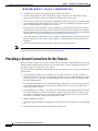
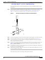
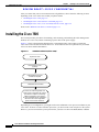
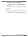
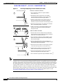
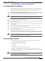
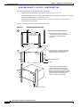
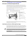
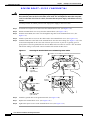
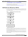
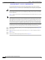
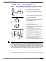
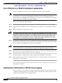
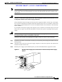
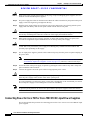
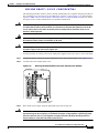
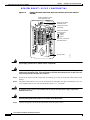
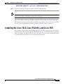
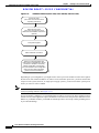
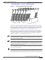
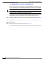
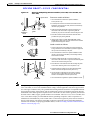
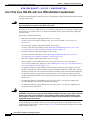
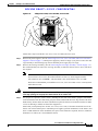
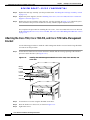
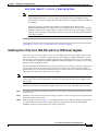
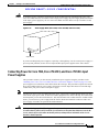
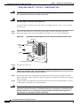
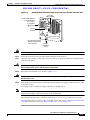
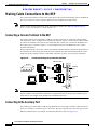
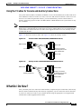
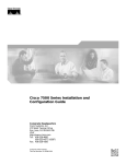
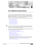
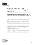
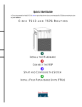
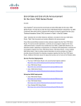
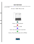
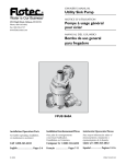
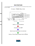
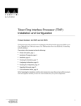
C H A P T E R
3
Installing a Cisco 7500 Series Router
This chapter provides guidelines and instructions you need for installing your Cisco 7500 series router,
including rack-mounting and general installation considerations. This chapter also includes a
rack-mounting procedure for the Cisco 7505; however, rack-mounting procedures for the Cisco 7507,
Cisco 7507-MX, Cisco 7513, Cisco 7513-MX, and Cisco 7576 are far more extensive and beyond the
scope of this publication.
For Cisco 7507, Cisco 7507-MX, Cisco 7513, Cisco 7513-MX, and Cisco 7576 rack-mounting
procedures, refer to the following two publications, which accompany the Cisco 7507, Cisco 7507-MX,
Cisco 7513, Cisco 7513-MX, and Cisco 7576 rack-mount kit (ACS-7000RMK=):
•
Cisco 7000 and Cisco 7507 Rack-Mount Kit Installation Instructions (Document Number
78-1058-xx)
•
Cisco 7513 and Cisco 7576 Rack-Mount Kit Installation Instructions
(Document Number 78-2023-xx)
Both of these publications are available on the Documentation CD-ROM and on Cisco.com.
Before you begin the installation procedures, we recommend that you also refer to the following sections
in Chapter 2, “Preparing for Installation”:
•
Site Environment, Chassis Temperature, and Airflow Guidelines, page 2-12
•
Equipment Rack-Mounting Guidelines, page 2-15
•
General Equipment Rack Ventilation Considerations, page 2-15
•
Cisco 7505 Rack-Mount Considerations, page 2-16
•
Cisco 7507 and Cisco 7507-MX Rack-Mount Considerations, page 2-18
•
Cisco 7513, Cisco 7513-MX, and Cisco 7576 Rack-Mount Considerations, page 2-20
Cisco 7500 Series General Installation Considerations
Before you begin the installation, the Cisco 7500 series router should already be in the area where you
will install it, and your installation location should already be determined. Ensure that you have planned
a clean, safe location for the chassis and that you have considered the following:
•
The location does not block the chassis front and rear, where the exhaust and intake vents for cooling
air are located; allow at least 6 inches (15.24 cm) of clearance. (Multiple chassis can be installed in
equipment racks with only one inch [2.54 cm] or more of vertical clearance.)
•
Consider future maintenance requirements; allow adequate clearance for installing or replacing
interface processors, or adding network connection cables or equipment.
Cisco 7500 Series Installation and Configuration Guide
OL-5008-03 B0
3-1
Chapter 3
Installing a Cisco 7500 Series Router
Providing a Ground Connection for the Chassis
REVIEW DRAFT—CISCO CONFIDENTIAL
Note
•
A temperature-controlled, air-conditioned area is ideal for the chassis.
•
Avoid crossing high-power cables with interface cables, which can cause interference in some
interface types. It will not always be possible to avoid this, but try to prevent it.
•
Check the power cable and power supply for compatibility with your power service; check the labels
on the equipment and ensure that the power service at your site is suitable for the chassis. Do not
mix AC- and DC-input power supplies in one chassis.
•
Do not place the router on the floor. Floors accumulate dust, which can be drawn into the chassis
interior by the fans. Excessive dust inside the chassis interior can cause overtemperature conditions
and component failures. A raised platform, rack, or sturdy table provides a cleaner environment than
the floor. (See the “Equipment Rack-Mounting Guidelines” section on page 2-15.
•
Allow approximately 19 inches (48.26 cm) of clearance behind the chassis for installing or replacing
processor modules, the fan or blower, power supplies, or attaching network connection cables or
equipment.
•
Provide an adequate chassis ground (earth) connection for your router chassis.
We strongly recommend that you see the next section, “Providing a Ground Connection for the Chassis,”
and follow the procedure to provide a chassis ground connection.
Providing a Ground Connection for the Chassis
Before you connect power or turn on power to your router, we strongly recommend that you provide an
adequate chassis ground (earth) connection for your router chassis. Chassis grounding receptacles are
provided on each Cisco 7500 series router chassis.
To ensure the chassis grounding connection that you provide is adequate, you will require the following
parts and tools:
•
One grounding lug—Must have two number-10 screw holes that have a 0.63-inch (16.002-mm)
spacing between them, and a wire receptacle large enough to accept a 6-AWG multistrand, copper
wire. (See Figure 3-1.) This lug is not available from Cisco; electrical-connector vendors provide
this type of grounding lug.
•
Two Phillips-head machine screws with locking washers—M5 (metric), 0.031-inch (0.8-mm) pitch,
0.315-inch (8-mm) length. These screws are not available from Cisco; they are available from a
commercial hardware vendor.
•
One grounding wire—6-AWG, 0.162-inch (4.115-mm) diameter, with (approximately) 0.108-inch
(2.743-mm) insulation, for a total wire diameter of (approximately) 0.27 inches (6.858 mm). The
wire length is dependent on your router location and site environment. This wire is not available
from Cisco; it is available from any commercial cable vendor.
•
Number 2 Phillips screwdriver.
•
Crimping tool large enough to accommodate the diameter of the wire receptacle on your grounding
lug.
•
Wire stripping tool large enough to accommodate 6-AWG wire.
Cisco 7500 Series Installation and Configuration Guide
3-2
OL-5008-03 B0
Chapter 3
Installing a Cisco 7500 Series Router
Providing a Ground Connection for the Chassis
REVIEW DRAFT—CISCO CONFIDENTIAL
Use the following procedure to attach the grounding lug to the chassis grounding receptacles on your
router chassis:
Step 1
Locate the chassis grounding receptacles on your router chassis. For the Cisco 7505, see Figure 1-2; for
the Cisco 7507, see Figure 1-5; for the Cisco 7507-MX, see Figure 1-8; for the Cisco 7513, see
Figure 1-11; for the Cisco 7513-MX, see Figure 1-14; for the Cisco 7576, see Figure 1-17.
Figure 3-1
Attaching a Grounding Lug to the Chassis Grounding Receptacles
Wire
Grounding lug
Chassis
grounding
receptacles
H10740
Screws
Step 2
Use the wire stripping tool to strip one end of the 6-AWG wire approximately 0.75 inches (19.05 mm).
Step 3
Insert the 6-AWG wire into the top of the wire receptacle on the grounding lug. (See Figure 3-1.)
Step 4
Use the crimping tool to carefully crimp the wire receptacle around the wire; this step is required to
ensure a proper mechanical connection.
Step 5
Insert the screws through the holes in the grounding lug and into the chassis grounding receptacles. (See
Figure 3-1.) Ensure that the grounding lug does not interfere with other router hardware, such as
processor modules and the like.
Step 6
Use the Phillips screwdriver to carefully tighten the two screws until the grounding lug is held firmly to
the chassis. Do not overtighten the screws.
Step 7
Prepare the other end of the 6-AWG wire and connect it to the appropriate grounding point at your site
to ensure an adequate chassis ground.
This completes the procedure for providing a chassis ground connection.
Cisco 7500 Series Installation and Configuration Guide
OL-5008-03 B0
3-3
Chapter 3
Installing a Cisco 7500 Series Router
Installing the Cisco 7505
REVIEW DRAFT—CISCO CONFIDENTIAL
After you ensure that your site environment meets all guidelines, choose from the following sections
depending on the Cisco 7500 series model you plan to install:
•
Installing the Cisco 7505, page 3-4
•
Installing the Cisco 7507 and Cisco 7507-MX, page 3-11
•
Installing the Cisco 7513, Cisco 7513-MX, and Cisco 7576, page 3-19
Then see the “What Do I Do Now?” section on page 3-33.
Installing the Cisco 7505
This section provides procedures for installing, rack-mounting, and attaching the cable-management
brackets on a Cisco 7505, and for connecting a power cable to the power supply.
Figure 3-2 shows a flowchart that illustrates the recommended order of procedures to install the
Cisco 7505 router and attach external cables to it. It also indicates the Cisco publications you should
refer to for more detailed information.
Figure 3-2
Installation Flowchart (Cisco 7505)
Unpack the router
Rack-mount the router
(optional)
Install additional processor
modules as required
Perform an initial configuration and
create a basic configuration file. Use the
procedures in Chapter 4 “Performing
a Basic Configuration of the System.”
For more information about configuration,
refer to the Cisco IOS configuration
guides and command references.
H9717
Make external connections
Depending on your configuration, you might need to insert additional or new processor modules in your
Cisco 7505. To insert or remove interface processors, you do not need to turn off power to the system.
However, you must turn off the system power before you insert or remove the RSP2, RSP4, or RSP8.
Cisco 7500 Series Installation and Configuration Guide
3-4
OL-5008-03 B0
Chapter 3
Installing a Cisco 7500 Series Router
Installing the Cisco 7505
REVIEW DRAFT—CISCO CONFIDENTIAL
You need a number 1 Phillips or 3/16-inch flat-blade screwdriver to remove any fillers (blank processor
carriers) and to tighten the captive installation screws that secure the processor module in its slot.
Whenever you handle modules, you should use an ESD-preventive wrist strap or other grounding device
to prevent ESD damage.
You can install interface processors (as shown in the following illustration) in any of the four interface
processor slots, numbered 0 through 3 from bottom to top when viewing the chassis from the rear. (See
the illustration of the Cisco 7505 in Figure 1-2.) The top slot (slot 4) must contain the RSP, which is a
required system component. The processor carriers are keyed so you cannot incorrectly install them in
the chassis slots.
Caution
To prevent the overheating of internal components, always install fillers in empty slots to maintain the
proper flow of cooling air across the cards. To prevent ESD damage, handle processor modules by the
handles and carrier edges only.
Figure 3-3 illustrates the procedures for removing and installing processor modules in the Cisco 7505.
Cisco 7500 Series Installation and Configuration Guide
OL-5008-03 B0
3-5
Chapter 3
Installing a Cisco 7500 Series Router
Installing the Cisco 7505
REVIEW DRAFT—CISCO CONFIDENTIAL
Figure 3-3
Removing and Replacing Processor Modules (Cisco 7505)
Card carrier guide (black)
Remove a module as follows:
1. Use a screwdriver to loosen the captive installation
screws (shown in A).
A
2. Simultaneously pull the ejector levers out to release
the module from the backplane connector (shown in B).
The levers should snap into their spring retainers.
Captive
installation
screw
B
3. Grasp the module handle with one hand and place your
other hand under the carrier to support and guide the
module as you pull it out of the slot. Avoid touching the card.
4. Place the removed module on an antistatic mat or antistatic
foam, or immediately install it in another slot.
5. Install a new module or a filler (MAS7K-BLANK) to keep
dust out of the chassis and to maintain proper airflow
through the chassis.
Install a module as follows:
1. Choose a slot for the new module and ensure that there is
enough clearance to accommodate any interface equipment
that you will connect directly to its ports.
C
2. Use a screwdriver to loosen the captive installation screws
(shown in A) and remove the filler (or the existing module)
from the slot to be filled.
3. Hold the module handle with one hand, and place your
other hand under the carrier to support the module and guide
it into the slot. Avoid touching the card.
4. Place the back of the module in the slot and align the guide
on the carrier with the groove in the slot (shown in A).
5. Carefully slide the module into the slot until the faceplate
makes contact with the ejector levers (shown in C).
7. Use a screwdriver to tighten the captive installation screws.
Note
H2620
6. Use the thumb and forefinger of each hand to push the
ejector lever flat against the module (shown in B).
The Cisco 7505 installation must comply with all applicable codes and is approved for use with copper
conductors only. The ground bond fastening hardware should be of compatible material and preclude
loosening, deterioration, and electrochemical corrosion of hardware and joined material. Attachment of
the chassis ground to the central office or other interior ground system should be made with a 6-AWG,
copper ground conductor at a minimum. The Cisco 7505 chassis employs two threaded M5 chassis
grounding receptacles, which are intended to be bonded directly to the central offices or other interior
ground system. These receptacle are located on the rear of the chassis. The chassis ground requires M5
screws and locking hardware, which are not included. (To properly ground the chassis, see the
“Providing a Ground Connection for the Chassis” section on page 3-2.)
Cisco 7500 Series Installation and Configuration Guide
3-6
OL-5008-03 B0
Chapter 3
Installing a Cisco 7500 Series Router
Installing the Cisco 7505
REVIEW DRAFT—CISCO CONFIDENTIAL
Cisco 7505 Installation Considerations
Before you install the Cisco 7505, decide where to install the router. If you intend to rack-mount the
router, proceed to the “Rack-Mounting the Cisco 7505” section on page 3-7. If you do not intend to
rack-mount the router, follow these steps to install the Cisco 7505 on a bench or tabletop:
Step 1
Make sure that your installation area is free of debris and dust.
Step 2
Make sure your path between the chassis and where you will place it is unobstructed.
Caution
To prevent damage to the chassis and components, never attempt to lift or tilt the chassis with the handles
on the interface processors. These handles are not designed to support the weight of the chassis.
Step 3
Carefully place the chassis on the tabletop or bench.
Step 4
On the chassis, ensure that all captive screws (on the processor modules, and so forth) are tightened and
the components are secure.
Step 5
For an AC-input power supply: push the cable retention clip away from the power receptacle and plug
in the power cable.
Step 6
For a DC-input power supply, proceed to the “Connecting Power to the Cisco 7505 DC-Input Power
Supply” section on page 3-9; otherwise, continue with Step 7.
Step 7
Secure the cable in the power supply receptacle by pushing the cable retention clip until it snaps into
place around the cable connector.
Step 8
Connect the opposite end of the power cable to an appropriate power source.
Caution
Do not turn on any power supplies until you are ready to power up the system. The interlock switch that
locks the power supply in the slot also turns on the system power.
Rack-Mounting the Cisco 7505
Before you begin the optional rack-mount installation, have the following tools and parts on hand:
Warning
•
Number 1 and number 2 Phillips screwdrivers
•
1/4-inch and 3/16-inch flat-blade screwdrivers
•
Tape measure
•
Level (optional)
•
Two chassis ears (rack brackets included with Cisco 7505)
•
Four M4 x 10-mm Phillips flat-head screws to secure the ears to the chassis (included)
•
Eight 10-32 x 3/8-inch slotted binderhead screws to secure the chassis ears to the mounting strips
(also called rails) in the rack
To prevent bodily injury when mounting or servicing this unit in a rack, you must take special
precautions to ensure that the system remains stable.
Cisco 7500 Series Installation and Configuration Guide
OL-5008-03 B0
3-7
Chapter 3
Installing a Cisco 7500 Series Router
Installing the Cisco 7505
REVIEW DRAFT—CISCO CONFIDENTIAL
The following guidelines are provided to ensure your safety:
– Mount this unit at the bottom of the rack if it is the only unit in the rack.
– When mounting this unit in a partially filled rack, load the rack from the bottom to the top with
the heaviest component at the bottom of the rack.
– If the rack is provided with stabilizing devices, install the stabilizers before mounting or
servicing the unit in the rack.
Figure 3-4 illustrates the Cisco 7505 rack-mount procedure.
Figure 3-4
Rack-Mounting the Cisco 7505
A
Rack-mount the chassis as follows:
18.312"
(46.51 cm)
hole centerline
to hole centerline
17.72" min.
(45 cm)
Mounting strip
1. Measure the space between the vertical
mounting strips on your rack. Verify that your
rack conforms to the measurements
(shown in A).
Mounting strip
2. Use the four M4 x 10-mm screws provided
to attach the ears to the sides of the chassis
(shown in B). Use two screws per ear.
B
M4 x 10-mm screws (4)
Ears (2)
H2908
C
3. To prevent injury, have someone help you
install the chassis in the rack (shown in C).
Use the 10-32 x 3/8-inch screws provided to
attach the ears to the mounting strips. Use four
screws per ear and mounting strip. Level the
chassis as required. Provide 2 inches of
clearance on each side of the chassis.
10-32 x 3/8-inch screws (8)
Cisco 7500 Series Installation and Configuration Guide
3-8
OL-5008-03 B0
Chapter 3
Installing a Cisco 7500 Series Router
Installing the Cisco 7505
REVIEW DRAFT—CISCO CONFIDENTIAL
Attaching the Cisco 7505 Cable-Management Brackets
The cable-management brackets for the Cisco 7505 are designed to keep network interface cables
untangled and orderly, and to prevent cables from hindering access to interface processors in the lower
slots. Install the brackets before connecting network interface cables to the interface processor ports;
otherwise, you will probably need to disconnect the cables to install the screws that secure the brackets.
The cable-management brackets attach to the interface processor end of the chassis.
To install the brackets, you need a number 1 Phillips screwdriver, two cable-management brackets, and
six M3 x 8-mm Phillips panhead screws.
Follow the steps in Figure 3-5 to install the cable-management brackets on the Cisco 7505.
Figure 3-5
Installing Cable-Management Brackets (Cisco 7505)
Bracket (2)
T
NS
OLE
1. Place a bracket on the rear of the chassis,
as shown.
CO
HA
SE
U
RE
CP
EJE
SLO SLO
T0 T1
NO
RM
AL
CT
LT
ROUTE SWITCH PROCESSOR
Install the cable management
brackets as follows:
2. Insert and finger-tighten three
M3 Phillips screws.
3. Use a screwdriver to tighten all three
screws.
4. Repeat 1, 2, and 3 for the other bracket.
M3 screw (6)
H2847
5. Route the interface cables through the
brackets.
If necessary, feed nylon or plastic cable ties through the holes provided in the brackets to secure
small-gauge cables or cable bundles. Loop cables where possible, but do not exceed the recommended
minimum bend radius for your optical-fiber cables.
Connecting Power to the Cisco 7505 DC-Input Power Supply
This section includes the procedure for connecting power to the Cisco 7505 DC-input power supply. The
DC-input power supply is already installed in the Cisco 7505 when you receive it. This procedure
assumes you ordered a DC-input power supply with your Cisco 7505 and requires a twin-lead, 10-AWG
cable for terminal block connections, a single 10-AWG wire for the ground connection, and a 3/16-inch
flat-blade screwdriver to loosen all captive screws on the terminal block and terminal block cover.
Warning
Before performing any of the following procedures, ensure that power is removed from the DC circuit.
To ensure that all power is OFF, locate the circuit breaker on the panel board that services the DC
circuit, switch the circuit breaker to the OFF position, and tape the switch handle of the circuit
breaker in the OFF position.
Cisco 7500 Series Installation and Configuration Guide
OL-5008-03 B0
3-9
Chapter 3
Installing a Cisco 7500 Series Router
Installing the Cisco 7505
REVIEW DRAFT—CISCO CONFIDENTIAL
Warning
Before working on a chassis or working near power supplies, unplug the power cord on AC units or
disconnect the power at the circuit breaker on DC units. This unit might have more than one power
cord. To reduce the risk of electric shock, disconnect the two power supply cords before servicing
the unit.
Use this procedure to connect power to a DC-input power supply in the Cisco 7505:
Step 1
Loosen the two captive screws that secure the terminal block cover. (See Figure 3-6a.)
Step 2
Pull the terminal block cover away from the terminal block. (See Figure 3-6b.)
Step 3
Feed the return (RTN) and –48V wires through the large hole in the terminal block cover. (See
Figure 3-6c.)
Step 4
Attach a nylon cable tie to secure the cable leads to the terminal block cover. (See Figure 3-6c.)
Step 5
Attach the RTN and –48V leads to the terminal block. Note the color coding. (See Figure 3-6d.) Color
code selection depends on the color code of the DC power source at your site. Typically, green or
green/yellow is used for ground, black is used for RTN, and red or white is used for –48V. No matter
which color coding is used, make certain it matches that used at the DC source.
Figure 3-6
Removing the Terminal Block Cover and Attaching Power Cables
a
b Caution: Do not strain the connection at the terminal block
-48/-60V —
20/16A
-48
RTN
-48/-60V —
20/16A
-48
RTN
POWER SUPPLY
TERM. BLOCK COVER
- USE ONLY WITH
NEC CLASS 3
WIRING
- USE COPPER
CONDUCTORS
POWER SUPPLY
TERM. BLOCK COVER
- USE ONLY WITH
NEC CLASS 3
WIRING
- USE COPPER
CONDUCTORS
Terminal block
cover and
captive screws
d
c
-48/-60V —
20/16A
-48
RTN
Cable strain relief
nylon cable tie
Step 6
Attach the ground cable to the ground terminal. (See Figure 3-6d.)
Step 7
Replace the terminal block cover. (See Figure 3-6b.)
Step 8
Tighten the captive screws on the terminal block cover. (See Figure 3-6a.)
H2537
Ground
terminal
Cisco 7500 Series Installation and Configuration Guide
3-10
OL-5008-03 B0
Chapter 3
Installing a Cisco 7500 Series Router
Installing the Cisco 7507 and Cisco 7507-MX
REVIEW DRAFT—CISCO CONFIDENTIAL
This completes the procedure for attaching DC-input cables to the Cisco 7505 DC-input power supply,
as well as procedures required to install the Cisco 7505.
For information on how to connect cables to the RSP, see the “Making Cable Connections to the RSP”
section on page 3-32, and then proceed to the “What Do I Do Now?” section on page 3-33.
Installing the Cisco 7507 and Cisco 7507-MX
This section provides procedures for installing your Cisco 7507 and Cisco 7507-MX and for connecting
power cables to power supplies. Figure 3-7 illustrates the order of procedures to install the Cisco 7507
or Cisco 7507-MX router and connect cables. It also indicates the Cisco publications you should refer
to for more detailed information.
Figure 3-7
Installation Flowchart (Cisco 7507 and Cisco 7507-MX)
Unpack the router
(Use Cisco 7000 and Cisco 7507
Unpacking Instructions)
Rack-mount the router
(Use Cisco 7000 and Cisco 7507
Rack-Mount Installation Instructions)
Insert power supplies
Perform an initial configuration and
create a basic configuration file. Use the
procedures in Chapter 4 “Performing
a Basic Configuration of the System.”
For more information about configuration,
refer to the Cisco IOS configuration
guides and command references.
H9718
Make external connections
Depending on your configuration, you might need to insert additional or new processor modules in your
Cisco 7507 or Cisco 7507-MX. To insert or remove interface processors, you do not need to turn off
power to the system. However, if the system is operating, you must turn off the system power before you
insert or remove an RSP2, RSP4, or RSP8.
You need a number 1 Phillips or 3/16-inch flat-blade screwdriver to remove any fillers (blank processor
module carriers) and to tighten the captive installation screws that secure the processor module in its slot.
Whenever you handle modules, you should use an ESD-preventive wrist strap or other grounding device
to prevent ESD damage.
Cisco 7500 Series Installation and Configuration Guide
OL-5008-03 B0
3-11
Chapter 3
Installing a Cisco 7500 Series Router
Installing the Cisco 7507 and Cisco 7507-MX
REVIEW DRAFT—CISCO CONFIDENTIAL
You can install interface processors (as shown in the following figure) in any of the five interface
processor slots, which are numbered 0 and 1, and 4 through 6, from left to right when viewing the chassis
from the rear. (See Figure 1-5.) Slot 2 or slot 3 contains the RSP, which is a required system component.
Caution
To prevent overheating internal components, always install fillers in empty slots to maintain the proper
flow of cooling air across the cards. To prevent ESD damage, handle processor modules by the handles
and carrier edges only.
Figure 3-8 illustrates the procedure for removing and replacing processor modules in the Cisco 7507 and
Cisco 7507-MX.
Note
In a Cisco 7507 or Cisco 7507-MX that has the high system availability (HSA) feature enabled and an
RSP2 configured as the system slave, online insertion and removal of any interface processor in either
CyBus might cause the slave RSP2 to reboot with a bus error or a processor memory parity error. The
master RSP will recover from this event and issue a “cBus Complex Restart” message. (Cisco 7507 or
Cisco 7507-MX systems that are configured with an RSP4 as the system slave are not affected and do
not experience this problem.) The RSP8 only supports the HSA feature when used with another RSP8.
If you have a Cisco 7507 or Cisco 7507-MX with an RSP2 configured as the system slave, we strongly
recommend that you use the following procedure to remove and replace an interface processor:
Step 1
Remove the slave RSP2 (also called a processor module) using the appropriate procedure in Figure 3-8.
Step 2
Wait 15 seconds.
Step 3
Remove and replace the interface processor (also called a processor module) using the procedures in
Figure 3-8.
Step 4
Wait 15 seconds.
Step 5
Reinsert the slave RSP2 using the appropriate procedure in Figure 3-8.
Cisco 7500 Series Installation and Configuration Guide
3-12
OL-5008-03 B0
Chapter 3
Installing a Cisco 7500 Series Router
Installing the Cisco 7507 and Cisco 7507-MX
REVIEW DRAFT—CISCO CONFIDENTIAL
Figure 3-8
Removing and Replacing Processor Modules— (Cisco 7507 and Cisco 7507-MX)
Bottom ejector lever
Remove a module as follows:
1. Use a screwdriver to loosen the captive installation
screws (shown in A).
A
2. Pull the ejector levers out to release the module from the
backplane connector (shown in B). The levers should snap
into their spring retainers.
Captive
installation
screw
Card
carrier
guide
Card
slot
3. Grasp the module handle with one hand and place your
other hand under the carrier to support and guide the
module as you pull it out of the slot. Avoid touching the card.
4. Place the removed module in the board racks that were
provided with your packing material.
5. Install a new module or a filler (MAS-7KBLANK or MASRSPBLANK) to keep dust out of the chassis and to maintain
proper airflow through the chassis.
Install a module as follows:
B
1. Choose a slot for the new module and ensure that there is
enough clearance to accommodate any interface equipment
that you will connect directly to its ports.
2. Use a screwdriver to loosen the captive installation screws
(shown in A) and remove the filler (or the existing module)
from the slot to be filled.
3. Hold the module handle with one hand, and place your
other hand under the carrier to support the module and guide
it into the slot. Avoid touching the card.
4. Place the back of the module in the slot and align the guide
on the carrier with the groove in the slot (shown in A).
C
5. Carefully slide the module into the slot until the faceplate
makes contact with the ejector levers (shown in C).
STOP!
on contact
Note
7. Use a screwdriver to tighten the captive installation screws.
H2622
6. Use the thumb and forefinger of each hand to push the
top lever down and the bottom lever up to fully seat the
module in the backplane connector (shown in B).
The Cisco 7507 or Cisco 7507-MX installation must comply with all applicable codes and is approved
for use with copper conductors only. The ground bond fastening hardware should be of compatible
material and preclude loosening, deterioration, and electrochemical corrosion of hardware and joined
material. Attachment of the chassis ground to the central office or other interior ground system should
be made with a 6-AWG, copper ground conductor at a minimum. The Cisco 7507 and Cisco 7507-MX
chassis employ two threaded M5 chassis grounding receptacles, which are intended to be bonded
directly to the central office or other interior ground system. These receptacles are located on the rear of
the chassis. The chassis ground requires M5 screws and locking hardware, which are not included. (To
properly ground the chassis, see the “Providing a Ground Connection for the Chassis” section on
page 3-2.)
Cisco 7500 Series Installation and Configuration Guide
OL-5008-03 B0
3-13
Chapter 3
Installing a Cisco 7500 Series Router
Installing the Cisco 7507 and Cisco 7507-MX
REVIEW DRAFT—CISCO CONFIDENTIAL
Cisco 7507 and Cisco 7507-MX Installation Considerations
Before you install the Cisco 7507 or Cisco 7507-MX, decide where to install the router.
Note
If you plan to rack-mount the router, refer to the publication Cisco 7000 and Cisco 7507 Rack-Mount
Kit Installation Instructions (Document Number 78-1058-xx or later), which shipped with the
rack-mount kit ACS-7000RMK=. If rack-mounting is not required, use the following procedure to install
a Cisco 7507 or Cisco 7507-MX on a bench or tabletop.
On the rear of the chassis, do the following:
Step 1
Check the ejector levers to ensure that each RSP and all interface processors are securely installed.
Step 2
Check the captive installation screws on each RSP and each interface processor, and tighten any that are
loose.
Step 3
Ensure that both power supply bays are empty.
Warning
Two people are required to lift the chassis. Grasp the chassis underneath the lower edge and lift with
both hands. To prevent injury, keep your back straight and lift with your legs, not your back. To prevent
damage to the chassis and components, never attempt to lift the chassis with the handles on the
power supplies or on the interface processors, or by the plastic panels on the front of the chassis.
These handles were not designed to support the weight of the chassis.
Step 4
Two people are required to perform this step. With a person positioned at either side of the chassis, grasp
the bottom edge of the chassis with one hand near the front and the other near the back. Slowly lift the
chassis in unison. Avoid sudden twists or moves to prevent injury.
Caution
To prevent damage to the chassis and components, never attempt to lift or tilt the chassis with the handles
on the interface processors. These handles are not designed to support the weight of the chassis.
Step 5
Place the chassis on a bench or tabletop where the air intake vent on the front of the chassis (the bottom
front panel) is not drawing in exhaust air from other equipment.
Step 6
Ensure that you have at least 3 or 4 feet (0.91 to 1.22 m) of clearance around the rear of the chassis. You
will need this space to install the power supplies and perform maintenance on the chassis.
Step 7
Make sure that the area in which you install the chassis is free of debris and dust. Also make sure your
path to the area is unobstructed.
After you correctly position the chassis, proceed to the next section, “Installing Cisco 7507 and Cisco
7507-MX Power Supplies.”
Installing Cisco 7507 and Cisco 7507-MX Power Supplies
Your Cisco 7507 or Cisco 7507-MX was shipped with the power supplies removed. One power supply
is shipped as standard equipment; a second power supply is optional. Install power supplies only after
you have finally installed or rack-mounted the chassis.
Cisco 7500 Series Installation and Configuration Guide
3-14
OL-5008-03 B0
Chapter 3
Installing a Cisco 7500 Series Router
Installing the Cisco 7507 and Cisco 7507-MX
REVIEW DRAFT—CISCO CONFIDENTIAL
Note
Warning
The following procedure applies to AC-input and DC-input power supplies, with specific differences
clearly noted. To prevent system problems, do not mix AC-input and DC-input power supplies in the
same chassis.
This product relies on the building’s installation for short-circuit (overcurrent) protection. Ensure that
a fuse or circuit breaker no larger than 120 VAC, 15A United States (240 VAC, 10A international) is used
on the phase conductors (all current-carrying conductors).
Always install the first power supply in the lower power supply bay and the second, if any, in the upper
bay. In systems with dual power supplies and when separate power sources are available, connect each
power supply to separate input lines, so in case of an input line failure, the second source will most likely
still be available.
If you install a second power supply in the upper bay, use a screwdriver to loosen the captive screw and
remove the cover plate. Save the plate and replace it whenever the system is operating with one power
supply.
Warning
Before working on a chassis or working near power supplies, unplug the power cord on AC units or
disconnect the power at the circuit breaker on DC units.
Following is the procedure for installing power supplies in the Cisco 7507 or Cisco 7507-MX:
Step 1
If possible, turn off the circuit breaker to which you will connect power and tape the breaker switch in
the off position.
Step 2
Check the switch on the face of the power supply, and place it in the off (O) position. The interlock tab
should not extend out of the unit.
Step 3
Hold the power supply by the handle and place your other hand underneath to support the bottom.
Figure 3-9
DC
IL
FA
AC
H1356a
WER
PO
Captive
installation
screw
Handling a Power Supply (Cisco 7507 and Cisco 7507-MX AC-Input Power Supply
Shown)
I
0
Cisco 7500 Series Installation and Configuration Guide
OL-5008-03 B0
3-15
Chapter 3
Installing a Cisco 7500 Series Router
Installing the Cisco 7507 and Cisco 7507-MX
REVIEW DRAFT—CISCO CONFIDENTIAL
Caution
Each power supply weighs approximately 20 lb (9 kg). To prevent dropping power supplies, use two
hands to remove and install power supplies.
Step 4
The power supply has rollers on the bottom end. Place the rollers inside the bay and position the power
supply so that it is aligned to go straight into the bay.
Step 5
Push the power supply all the way into the bay. Do not use unnecessary force; firmly push the power
supply back into the bay until its front panel is flush with the chassis rear panel.
Caution
Step 6
When inserting a power supply into the bay, do not use unnecessary force; slamming the power supply
into the bay can damage the connectors on the rear of the supply and inside the chassis.
While firmly pressing the power supply faceplate so that is flush with the chassis rear panel, use a
screwdriver to tighten the captive installation screw on the top of the power supply.
Caution
Always tighten the captive installation screw at the top of the power supply before turning on the power
switch. This screw prevents the power supply from shifting away from the internal connector and
provides proper grounding for the supply.
Step 7
For AC-input power supplies: push the cable retention clip away from the power receptacle and plug in
the power cable.
Note
For DC-input power supplies, proceed to the “Connecting Power to Cisco 7507 or Cisco
7507-MX DC-Input Power Supplies” section on page 3-16; otherwise, continue with Step 8.
Step 8
Secure the cable in the power supply receptacle by pushing the cable retention clip until it snaps into
place around the cable connector.
Step 9
Connect the opposite end of the power cable to an appropriate power source.
Caution
Do not turn on any power supplies until you are ready to power up the system. The interlock switch that
locks the power supply in the slot also turns on the system power.
If you are installing a second power supply, repeat Step 2 through Step 9. We recommend you connect
the second power supply to a secondary power source for redundancy.
Note
To prevent system problems, do not mix AC-input and DC-input power supplies in the same chassis.
Connecting Power to Cisco 7507 or Cisco 7507-MX DC-Input Power Supplies
This section includes the procedure for connecting power to the Cisco 7507 or Cisco 7507-MX DC-input
power supplies.
Cisco 7500 Series Installation and Configuration Guide
3-16
OL-5008-03 B0
Chapter 3
Installing a Cisco 7500 Series Router
Installing the Cisco 7507 and Cisco 7507-MX
REVIEW DRAFT—CISCO CONFIDENTIAL
The following procedure assumes you have already installed the power supplies using the procedure in
the “Installing Cisco 7507 and Cisco 7507-MX Power Supplies” section on page 3-14. The procedure
requires 8-AWG cable for terminal block connections and a 3/16-inch flat-blade screwdriver to loosen
the captive screws on the terminal block cover and the terminal block.
Warning
Before performing any of the following procedures, ensure that power is removed from the DC circuit.
To ensure that all power is OFF, locate the circuit breaker on the panel board that services the DC
circuit, switch the circuit breaker to the OFF position, and tape the switch handle of the circuit
breaker in the OFF position.
Warning
Before working on a chassis or working near power supplies, unplug the power cord on AC units or
disconnect the power at the circuit breaker on DC units.
Warning
This unit might have more than one power cord. To reduce the risk of electric shock, disconnect the
two power supply cords before servicing the unit.
Use this procedure to connect power to DC-input power supplies in the Cisco 7507 or Cisco 7507-MX:
Step 1
Using a screwdriver, loosen the captive installation screws on the terminal block cover. Figure 3-10
Step 2
Lift and remove the terminal block cover.
Figure 3-10
Removing the Terminal Block Cover (Cisco 7507 and Cisco 7507-MX)
DO NOT SHIP WITH POWER SUPPLY
INSTALLED
FASTENER TO BE FULLY ENGAGED
BEFORE OPERATING POWER SUPPLY
OU
T
INP FAIL
UT
PO
WE
INPUT VOLTAGE : 40-72 V=
INPUT CURRENT : 24-13A
H2531
R
Captive installation screws
on terminal block cover
Step 3
Warning
Wire the DC power supply using the appropriate lugs at the wiring end.
The illustration shows the DC power supply terminal block. Wire the DC power supply using the
appropriate lugs at the wiring end, as illustrated. The proper wiring sequence is ground to ground,
positive to positive (line to L), and negative to negative (neutral to N). Note that the ground wire
should always be connected first and disconnected last.
Cisco 7500 Series Installation and Configuration Guide
OL-5008-03 B0
3-17
Chapter 3
Installing a Cisco 7500 Series Router
Installing the Cisco 7507 and Cisco 7507-MX
REVIEW DRAFT—CISCO CONFIDENTIAL
Figure 3-11
Installing the Power Cable Leads, Nylon Ties, and Cover (Cisco 7507 and Cisco
7507-MX)
Captive installation screws
on terminal block cover
DO NOT SHIP WITH POWER SUPPLY
INSTALLED
FASTENER TO BE FULLY ENGAGED
BEFORE OPERATING POWER SUPPLY
Power supply captive
installation screw
OU
T
INP FAIL
UT
PO
WE
Terminal block cover
(removable)
R
Power leads attached
to terminal block
( ) negative
( ) positive
( ) ground
Nylon ties on the cable
and metal bracket
INPUT VOLTAGE : 40-72 V=
INPUT CURRENT : 24-13A
I
DC-input cable
NO SERVICEABLE COMPONENTS INSIDE
H2486
O
Warning
Incorrectly wiring the terminal block could create a dangerous shock hazard and could damage the
power supply, power source, and the chassis components.
Warning
When stranded wiring is required, use approved wiring terminations, such as closed-loop or
spade-type with upturned lugs. These terminations should be the appropriate size for the wires and
should clamp both the insulation and conductor.
Step 4
Provide strain relief for the DC-input cable by attaching two nylon ties around the cable and the metal
bracket.
Step 5
Install the terminal block cover over the terminal block, and tighten the captive installation screws. Do
not overtighten these screws. The recommended torque is 8.2 0.4 inch-lb.
Warning
To prevent a short-circuit or shock hazard after wiring the DC-input power supply, replace the
terminal block cover.
Warning
After wiring the DC power supply, remove the tape from the circuit breaker switch handle turn on
power by moving the handle of the circuit breaker to the ON position.
Step 6
Connect the opposite end of the DC-input cable to the DC power source.
Cisco 7500 Series Installation and Configuration Guide
3-18
OL-5008-03 B0
Chapter 3
Installing a Cisco 7500 Series Router
Installing the Cisco 7513, Cisco 7513-MX, and Cisco 7576
REVIEW DRAFT—CISCO CONFIDENTIAL
Step 7
Note
If you are installing a second power supply, repeat Step 1 through Step 6.
Do not turn on any power supplies until you are ready to power up the system. The interlock switch that
locks the power supply in the slot also turns on the system power.
This completes the procedure for attaching power cables to the DC-input power supplies in a Cisco 7507
or Cisco 7507-MX, as well as the procedures required to install the Cisco 7507 or Cisco 7507-MX.
For information on how to connect cables to the RSP, see the “Making Cable Connections to the RSP”
section on page 3-32, and then proceed to the “What Do I Do Now?” section on page 3-33.
Installing the Cisco 7513, Cisco 7513-MX, and Cisco 7576
This section provides procedures for installing your Cisco 7513, Cisco 7513-MX, or Cisco 7576 and
connecting power cables to power supplies. The flowchart in Figure 3-12 illustrates the recommended
order of procedures to install a Cisco 7513, Cisco 7513-MX, or Cisco 7576 router. It also indicates the
Cisco publications you should refer to for more detailed information.
Cisco 7500 Series Installation and Configuration Guide
OL-5008-03 B0
3-19
Chapter 3
Installing a Cisco 7500 Series Router
Installing the Cisco 7513, Cisco 7513-MX, and Cisco 7576
REVIEW DRAFT—CISCO CONFIDENTIAL
Figure 3-12
Installation Flowchart (Cisco 7513, Cisco 7513-MX, and Cisco 7576)
Unpack the router
(Use Cisco 7513 and Cisco 7576
Unpacking Instructions)
Rack-mount the router
(Use Cisco 7513 and Cisco 7576
Rack-Mount Kit Installation Instructions )
(optional)
Insert power supplies
Perform an intial configuration and
create a basic configuration file. Use the
procedures in Chapter 4 “Performing
a Basic Configuration of the System.”
For more information about configuration,
refer to the Cisco IOS configuration
guides and command reference.
122371
Make all external connections
Depending on your configuration, you might need to remove processor modules to reduce the weight of
the chassis for rack-mount installation. To remove or insert interface processors, you do not need to turn
off power to the system; however, on single power supply systems, you must turn off the system power
before you insert or remove an RSP.
Note
Place removed processor modules in the collapsible, black-cardboard board racks that were provided
with your packing material. (See Figure 3-13.)
You need a number 1 Phillips or 3/16-inch flat-blade screwdriver to remove any fillers (blank processor
module carriers) and to tighten the captive installation screws that secure the processor module in its slot.
Whenever you handle modules, you should use an ESD-preventive wrist strap or other grounding device
to prevent ESD damage.
Cisco 7500 Series Installation and Configuration Guide
3-20
OL-5008-03 B0
Chapter 3
Installing a Cisco 7500 Series Router
Installing the Cisco 7513, Cisco 7513-MX, and Cisco 7576
REVIEW DRAFT—CISCO CONFIDENTIAL
Temporary Storage for Removed Processor Modules
H3589
Figure 3-13
In the Cisco 7513 and Cisco 7513-MX you can install interface processors in any of the 11 interface
processor slots, numbered 0 through 5 for CyBus 0, and 8 through 12 for CyBus 1, from left to right
when viewing the chassis from the rear. Slot 6 and slot 7 are the RSP slots and are reserved for the RSP2,
RSP4, or RSP8, which is a required system component. (See the illustration of the card cage and
processor modules in Figure 1-11 in Chapter 1, “Cisco 7500 Series Product Overview.”)
The backplane of the Cisco 7576 features two routers (router A and router B) on a single backplane.
Router A consists of two CyBuses and uses interface processor slots 0 through 5, with an RSP4 (or
RSP8) in slot 6. Router B also consists of two CyBuses. It uses interface processor slots 8 through 12,
with an RSP4 (or RSP8) in slot 7. (See the illustration of the card cage and processor modules in
Figure 1-17 in Chapter 1, “Cisco 7500 Series Product Overview.”)
Caution
If you are configuring only one of the two routers that make up the Cisco 7576, make sure to configure
router A instead of router B. To configure router A, install an RSP4 or RSP8 in slot 6, and install
interface processors in slots 0 through 5.
Caution
To prevent the overheating of internal components, always install interface processor fillers
(MAS-7KBLANK=) and RSP fillers (MAS-RSPBLANK=) in the appropriate empty chassis slots to
maintain the proper airflow across the processor modules. To prevent ESD damage, handle processor
modules by the handles and carrier edges only.
Figure 3-14 illustrates the procedures for removing and replacing processor modules in the Cisco 7513,
Cisco 7513-MX, and Cisco 7576.
Note
In a Cisco 7513 or Cisco 7513-MX that has the high system availability (HSA) feature enabled and an
RSP2 configured as the system slave, online insertion and removal (OIR) of any interface processor in
either CyBus might cause the slave RSP2 to reboot with a bus error or a processor memory parity error.
Cisco 7500 Series Installation and Configuration Guide
OL-5008-03 B0
3-21
Chapter 3
Installing a Cisco 7500 Series Router
Installing the Cisco 7513, Cisco 7513-MX, and Cisco 7576
REVIEW DRAFT—CISCO CONFIDENTIAL
The master RSP will recover from this event and issue a “cBus Complex Restart” message. (Cisco 7513
and Cisco 7513-MX systems that are configured with an RSP4 as the system slave are not affected and
do not experience this problem.) The RSP8 only supports the HSA feature when used with another RSP8.
Note
The Cisco 7576 does not support HSA. The RSP in slot 6 is automatically the system master for router
A and the RSP in slot 7 is automatically the system master for router B.
If you have a Cisco 7513 or Cisco 7513-MX with an RSP2 configured as the system slave, we strongly
recommend that you use the following procedure to remove and replace an interface processor:
Step 1
Remove the slave RSP2 (also called a processor module) using the appropriate procedure in Figure 3-14.
Step 2
Wait 15 seconds.
Step 3
Remove and replace the interface processor (also called a processor module) using the procedures in
Figure 3-14.
Step 4
Wait 15 seconds.
Step 5
Reinsert the slave RSP2 using the appropriate procedure in Figure 3-14.
Cisco 7500 Series Installation and Configuration Guide
3-22
OL-5008-03 B0
Chapter 3
Installing a Cisco 7500 Series Router
Installing the Cisco 7513, Cisco 7513-MX, and Cisco 7576
REVIEW DRAFT—CISCO CONFIDENTIAL
Figure 3-14
Removing and Replacing Processor Modules (*Cisco 7513, Cisco 7513-MX, and
Cisco 7576)
Bottom ejector lever
Remove a module as follows:
1. Use a screwdriver to loosen the captive installation
screws (shown in A).
A
Captive
installation
screw
Card
carrier
guide
Card
slot
2. Pull the ejector levers out to release the module from the
backplane connector (shown in B). The levers should snap
into their spring retainers.
3. Grasp the module handle with one hand and place your
other hand under the carrier to support and guide the
module as you pull it out of the slot. Avoid touching the card.
4. Place the removed module in the board racks that were
provided with your packing material.
5. Install a new module or a filler (MAS-7KBLANK or MASRSPBLANK) to keep dust out of the chassis and to maintain
proper airflow through the chassis.
Install a module as follows:
B
1. Choose a slot for the new module and ensure that there is
enough clearance to accommodate any interface equipment
that you will connect directly to its ports.
2. Use a screwdriver to loosen the captive installation screws
(shown in A) and remove the filler (or the existing module)
from the slot to be filled.
3. Hold the module handle with one hand, and place your
other hand under the carrier to support the module and guide
it into the slot. Avoid touching the card.
4. Place the back of the module in the slot and align the guide
on the carrier with the groove in the slot (shown in A).
C
5. Carefully slide the module into the slot until the faceplate
makes contact with the ejector levers (shown in C).
STOP!
on contact
Note
7. Use a screwdriver to tighten the captive installation screws.
122304
6. Use the thumb and forefinger of each hand to push the
top lever down and the bottom lever up to fully seat the
module in the backplane connector (shown in B).
Wiring codes prevent 20A plugs from being used with most equipment rack power strips. A Cisco 7513,
Cisco 7513-MX, or Cisco 7576 installation must comply with all applicable codes and is approved for
use with copper conductors only. The ground bond fastening hardware should be of compatible material
and preclude loosening, deterioration, and electrochemical corrosion of hardware and joined material.
Attachment of the chassis ground receptacles to the central office or other interior ground system should
be made with a 6-AWG, copper ground conductor at a minimum. The Cisco 7513, Cisco 7513-MX, and
Cisco 7576 chassis employ two threaded M5 chassis grounding receptacles. These receptacles are
intended to be bonded directly to the central office or other interior ground system, and are located on
the rear of the chassis. The chassis grounding receptacles require M5 screws and locking hardware,
which are not included. (To properly ground the chassis, see the “Providing a Ground Connection for the
Chassis” section on page 3-2.)
Cisco 7500 Series Installation and Configuration Guide
OL-5008-03 B0
3-23
Chapter 3
Installing a Cisco 7500 Series Router
Installing the Cisco 7513, Cisco 7513-MX, and Cisco 7576
REVIEW DRAFT—CISCO CONFIDENTIAL
Cisco 7513, Cisco 7513-MX, and Cisco 7576 Installation Considerations
The chassis should already be in the area where you will install it, and your installation location should
already be determined.
Warning
Before working on a chassis or working near power supplies, unplug the power cord on AC units or
disconnect the power at the circuit breaker on DC units.
The Cisco 7513, Cisco 7513-MX, and Cisco 7576 chassis weigh 160 lb (72.6 kg) fully configured and
can be lifted by two people; however, to make the installation easier, consider removing components
from the chassis.
Specifically, consider the following:
•
Each processor module weighs approximately 2.5 lb (1.13 kg).
(To remove processor modules from the Cisco 7513, Cisco 7513-MX, or Cisco 7576, see
Figure 3-14.)
•
The card cage assembly weighs approximately 15 lb (6.8 kg).
(To remove the card cage assembly, see the “Removing and Replacing the Cisco 7513, Cisco
7513-MX, and Cisco 7576 Card Cage Assembly” section on page 7-5.)
•
The blower module weighs approximately 10 lb (4.55 kg).
(To remove the blower assembly, see the “Removing and Replacing the Cisco 7513, Cisco
7513-MX, and Cisco 7576 Blower Module” section on page 7-10.)
•
Each power supply weighs approximately 25 lb (11.34 kg).
(Power supplies are not installed when you receive your Cisco 7513, Cisco 7513-MX, or
Cisco 7576. To install power supplies, see the “Installing Cisco 7513, Cisco 7513-MX, and Cisco
7576 Power Supplies” section on page 3-27.)
Warning
•
To lighten the chassis by approximately 110 lb (49.9 kg), remove the power supplies, processor
modules (assuming all 13 slots are filled), card cage assembly, and blower module before moving
the chassis into the rack. (We recommend removing all of these items for rack-mount installation.)
•
To lighten the chassis by approximately 100 lb (40.8 kg), remove the power supplies, processor
modules (assuming all thirteen slots are filled), and card cage assembly before moving the chassis
into the rack.
•
To lighten the chassis by approximately 85 lb (38.6 kg), remove only the power supplies and
processor modules before moving the chassis into the rack.
•
To lighten the chassis by approximately 50 lb (22.7 kg), remove only the power supplies before
moving the chassis into the rack.
Two people are required to lift the chassis. Grasp the chassis underneath the lower edge and lift with
both hands. To prevent injury, keep your back straight and lift with your legs, not your back. To prevent
damage to the chassis and components, never attempt to lift the chassis with the handles on the
power supplies, interface processors, or the blower module. These handles were not designed to
support the weight of the chassis.
To prevent damage to the chassis, lift the chassis by placing one hand on a side handle and the other
beneath the front of the chassis, as shown in Figure 3-15. Do not lift the chassis using the blower module
handle or the air intake vent.
Cisco 7500 Series Installation and Configuration Guide
3-24
OL-5008-03 B0
Chapter 3
Installing a Cisco 7500 Series Router
Installing the Cisco 7513, Cisco 7513-MX, and Cisco 7576
REVIEW DRAFT—CISCO CONFIDENTIAL
Figure 3-15
Lifting a Cisco 7513, Cisco 7513-MX, or Cisco 7576
POWER
A
POWER
H3118
B
Follow these steps to install the Cisco 7513, Cisco 7513-MX, and Cisco 7576:
Step 1
Remove all power supplies. (See the “Removing Cisco 7513, Cisco 7513-MX, and Cisco 7576 Power
Supplies” section on page 7-3.) Both power supply bays must be empty if you plan to remove the card
cage assembly in the following step. Ensure that both power supply bays are empty.
Step 2
Remove the card cage assembly. (See the “Removing the Card Cage Assembly” section on page 7-5.)
We recommend that you remove the card cage assembly to make the chassis easier to move; but this is
not required.
Note
To mount the router in a rack, refer to the publication Cisco 7513 and Cisco 7576 Rack-Mount
Kit Installation Instructions (Document Number 78-1058-xx), which shipped with the
rack-mount kit ACS-7000RMK=. This document is also used with the Cisco 7513-MX.
We do not recommend that you install the Cisco 7513, Cisco 7513-MX, or Cisco 7576 anywhere
other than in a rack.
Warning
Step 3
To prevent injury, avoid sudden twists or moves. To prevent damaging the air intake vent below the
card cage opening, do not grasp the chassis below the air intake vent.
Two people are required to lift the chassis. Standing on each side of the chassis, grasp the side handle
with one hand and with the other hand, grasp the chassis underneath the lower edge and lift with both
hands. Slowly lift the chassis in unison. (Remember to place the chassis in a location where the air intake
vent is not drawing in exhaust air from other equipment.)
Ensure that you temporarily have at least 2 to 3 feet (0.6 to 0.9 m) of clearance around the rear of the
chassis. You will need this space to install the power supplies, perform maintenance on the chassis, and
observe LED indications. After installation, this space can be reduced as required; however, maintain a
minimum of 19 inches (48.3 cm) behind the chassis.
Cisco 7500 Series Installation and Configuration Guide
OL-5008-03 B0
3-25
Chapter 3
Installing a Cisco 7500 Series Router
Installing the Cisco 7513, Cisco 7513-MX, and Cisco 7576
REVIEW DRAFT—CISCO CONFIDENTIAL
Step 4
Replace the card cage assembly. (See the procedure in the “Installing the Card Cage Assembly” section
on page 7-9.)
Step 5
Replace the power supplies. (See the “Installing Cisco 7513, Cisco 7513-MX, and Cisco 7576 Power
Supplies” section on page 3-27.)
Step 6
Replace the processor modules in the card cage. (See the procedure in Figure 3-14.) Check all ejector
levers and ensure the processor modules are securely installed; tighten any that are loose.
This completes the procedure for installing the Cisco 7513, Cisco 7513-MX, and Cisco 7576. Proceed
to the “Attaching the Cisco 7513, Cisco 7513-MX, and Cisco 7576 Cable-Management Bracket” section
on page 3-26.
Attaching the Cisco 7513, Cisco 7513-MX, and Cisco 7576 Cable-Management
Bracket
Use the following procedure to install the cable-management bracket. You will need a large flat-blade
screwdriver for this procedure.
Step 1
Locate the two slotted screws between the blower module and the card cage opening at the interface
processor end of the router. (See Figure 3-16.)
Figure 3-16
Installing the Cable-Management Bracket on a Cisco 7513, Cisco 7513-MX, and
Cisco 7576
Blower
module
Loosen
screws (2)
Bracket
122372
Card cage
Step 2
Loosen these two screws using the flat-blade screwdriver.
Step 3
Place the bracket over the screws, as shown in Figure 3-16.
Step 4
Tighten the screws.
Cisco 7500 Series Installation and Configuration Guide
3-26
OL-5008-03 B0
Chapter 3
Installing a Cisco 7500 Series Router
Installing the Cisco 7513, Cisco 7513-MX, and Cisco 7576
REVIEW DRAFT—CISCO CONFIDENTIAL
Note
When you install the network interface cables, route the cables to and through the
cable-management bracket. If you are using very thin cables that slip through the bracket
openings, insert cable ties through the holes in the bracket and wrap them around the cables to
secure them.
It might be necessary to bundle longer cables to avoid tangling them. Do this at the
cable-management bracket or at the rack, but leave enough room to remove processor modules
and power supplies and to change cables as required. Do not block the power supply or chassis
intake air vents with cables. Verify that the cables do not interfere with removal and installation
of the blower module.
This completes the procedure for installing the cable-management bracket. Proceed to the next section,
“Installing Cisco 7513, Cisco 7513-MX, and Cisco 7576 Power Supplies.”
Installing Cisco 7513, Cisco 7513-MX, and Cisco 7576 Power Supplies
Your Cisco 7513, Cisco 7513-MX, or Cisco 7576 was shipped with the power supplies removed. The
Cisco 7513 and Cisco 7513-MX are shipped with one power supply as standard equipment; a second
power supply is optional equipment. When purchased new (not upgraded), the Cisco 7576 comes with
two AC-input power supplies as standard equipment. Install power supplies only after you have finally
installed or rack-mounted the chassis.
Based on the NFPA 70 National Electrical Code, you should use a 35-amp (A) overcurrent protector to
meet the requirement for the overcurrent protector size of 125 percent of the load current, which is
approximately 27A. An overcurrent protector rated for 30A can be used only if it has been listed by the
safety agency for operation at 100 percent of its rating.
Note
The following procedure applies to AC-input and DC-input power supplies, with specific differences
clearly noted. To prevent system problems, do not mix AC-input and DC-input power supplies in the
same chassis.
Follow this procedure to install a power supply in the Cisco 7513, Cisco 7513-MX, and Cisco 7576:
Step 1
If possible, turn off the circuit breaker to which you will connect power and tape the breaker switch in
the off position.
Step 2
Check the switch on the face of the power supply, and place it in the off (O) position. The interlock tab
should not extend out of the unit.
Step 3
Hold the supply as shown in Figure 3-17 and slide it into the power supply bay. Push the supply all the
way into the chassis until the sides are flush against the chassis frame. To prevent damaging the
backplane connector, do not jam the power supply into the bay.
Cisco 7500 Series Installation and Configuration Guide
OL-5008-03 B0
3-27
Chapter 3
Installing a Cisco 7500 Series Router
Installing the Cisco 7513, Cisco 7513-MX, and Cisco 7576
REVIEW DRAFT—CISCO CONFIDENTIAL
Figure 3-17
FAN
OK
OUTPUT
FAIL
H5267
AC
OK
Handling a Power Supply (Cisco 7513, Cisco 7513-MX, and Cisco 7576 AC-Input Power
Supply Shown)
I
0
Step 4
While firmly pressing the power supply faceplate so that is flush with the chassis rear panel, use a large
slotted screwdriver to tighten the captive screw that secures the power supply to the chassis frame.
Figure 3-18
AC
OK
Installing a Power Supply (Cisco 7513, Cisco 7513-MX, and Cisco 7576 AC-Input
Power Supply Shown)
FAN
OK
OUTPUT
FAIL
AC
OK
FAN
OK
OUTPUT
FAIL
POWER
B
I
I
0
122306
0
Captive screws
Step 5
For AC-input power supplies—push the cable retention clip away from the power receptacle, and plug
in the power cable.
Note
For DC-input power supplies, proceed to the “Connecting Power to Cisco 7513, Cisco
7513-MX, and Cisco 7576 DC-Input Power Supplies” section on page 3-29; otherwise, continue
with Step 6.
Step 6
Secure the cable in the power supply receptacle by pushing the cable retention clip until it snaps into
place around the cable connector.
Step 7
After the AC power cable is connected, reconnect the power cable at the power source, remove the tape
(if any) that you placed on the breaker switch, but do not turn on the breaker or power to the power
supply.
Cisco 7500 Series Installation and Configuration Guide
3-28
OL-5008-03 B0
Chapter 3
Installing a Cisco 7500 Series Router
Installing the Cisco 7513, Cisco 7513-MX, and Cisco 7576
REVIEW DRAFT—CISCO CONFIDENTIAL
Caution
To maintain agency compliance requirements and meet EMI emissions standards in the Cisco 7513,
Cisco 7513-MX, and Cisco 7576 chassis with a single power supply, the power supply blank must remain
in the empty power supply bay. Do not remove this blank from the chassis except to install a second
power supply.
Power Supply Blank (Cisco 7513, Cisco 7513-MX, and Cisco 7576)
122307
Figure 3-19
Captive screw
If you are installing both power supplies, repeat Step 1 through Step 7 for the second power supply. To
prevent system problems, do not mix AC-input and DC-input power supplies in the same chassis.
Connecting Power to Cisco 7513, Cisco 7513-MX, and Cisco 7576 DC-Input
Power Supplies
This procedure assumes you have already installed the power supplies using the procedure in the
“Installing Cisco 7513, Cisco 7513-MX, and Cisco 7576 Power Supplies” section on page 3-27. The
power supplies rest on the floor of the chassis under the card cage. This procedure requires an 8-mm nut
driver and 8-AWG cable for power supply connections. The DC-input cable must be routed through
conduit from your power source to the power supply.
Note
For the Cisco 7513, Cisco 7513-MX, and Cisco 7576, you provide a conduit through which you must
route the DC-input power cable. If cables from other equipment are in front of the bay, move them aside
and temporarily secure them with cable ties. You must disconnect the conduit from the conduit bracket
before you can remove a power supply from the chassis. Route and attach the conduit to make each
power supply accessible for replacement and maintenance.
Warning
Before performing any of the following procedures, ensure that power is removed from the DC circuit.
To ensure that all power is OFF, locate the circuit breaker on the panel board that services the DC
circuit, switch the circuit breaker to the OFF position, and tape the switch handle of the circuit
breaker in the OFF position.
Cisco 7500 Series Installation and Configuration Guide
OL-5008-03 B0
3-29
Chapter 3
Installing a Cisco 7500 Series Router
Installing the Cisco 7513, Cisco 7513-MX, and Cisco 7576
REVIEW DRAFT—CISCO CONFIDENTIAL
Warning
Before working on a chassis or working near power supplies, unplug the power cord on AC units or
disconnect the power at the circuit breaker on DC units.
Warning
This unit might have more than one power cord. To reduce the risk of electric shock, disconnect the
two power supply cords before servicing the unit.
Use this procedure to connect power to DC-input power supplies in the Cisco 7513, Cisco 7513-MX,
and Cisco 7576:
Step 1
Turn off (O) the system power switch on the power supply you want to attach DC-input cable.
Step 2
Remove the 8-mm screws on the terminal block cover so the cover is free of the terminal block.
Figure 3-20
Removing the Terminal Block Cover (Cisco 7513, Cisco 7513-MX, and Cisco 7576)
Remove
DC
FAN OUTPUT
OK
OK
FAIL
Terminal
block
cover
Remove
I
DC-input power supply
Step 3
Warning
122308
0
Lift and remove the cover.
When stranded wiring is required, use approved wiring terminations, such as closed-loop or
spade-type with upturned lugs. These terminations should be the appropriate size for the wires and
should clamp both the insulation and the conductor.
Step 4
Route the DC-input power cable through the conduit from your power source, through the conduit
bracket on the power supply, and make a sufficient length of wire available to attach to the three terminal
block connections.
Step 5
Attach and tighten the conduit to the conduit bracket. How this conduit is attached depends on your site;
its attachment is beyond the scope of this publication.
Warning
The illustration shows the DC power supply terminal block. Wire the DC power supply using the
appropriate lugs at the wiring end, as illustrated. The proper wiring sequence is ground to ground,
positive to positive (line to L), and negative to negative (neutral to N). Note that the ground wire
should always be connected first and disconnected last.
Cisco 7500 Series Installation and Configuration Guide
3-30
OL-5008-03 B0
Chapter 3
Installing a Cisco 7500 Series Router
Installing the Cisco 7513, Cisco 7513-MX, and Cisco 7576
REVIEW DRAFT—CISCO CONFIDENTIAL
Figure 3-21
Attaching the DC-Input Power Cable (Cisco 7513, Cisco 7513-MX, and Cisco 7576)
DC-input
cable (8-AWG)
Power leads attached
to terminal block
(+) Positive
(–) Negative
( ) Ground
DC
FAN OUTPUT
OK
OK
FAIL
Conduit
bracket
I
DC-input power supply
with the terminal block
cover removed
Warning
122369
0
Captive
installation
screw
When installing the unit, the ground connection must always be made first and disconnected last.
Step 6
Attach the ground wire to the ground terminals using the 8-mm nut driver.
Step 7
Check the power supply’s wiring and wiring color code to verify that it matches the wiring and color
code at the DC source.
Warning
Step 8
Warning
Step 9
Incorrectly wiring the terminal block could create a dangerous shock hazard and could damage the
power supply, power source, and the chassis components.
Replace the terminal block cover. (Refer to Figure 3-19.)
To prevent a short-circuit or shock hazard after wiring the DC-input power supply, replace the
terminal block cover.
After the DC power cable leads are connected to the DC-input power supply, reconnect the power cable
at the power source.
If you plan to add a second power supply, repeat Step 1 through Step 9.
Note
Do not turn on any power supplies until you are ready to power up the system. The interlock switch that
locks the power supply in the slot also turns on the system power.
This completes the procedures required to install the Cisco 7513, Cisco 7513-MX, and Cisco 7576.
For information on how to connect cables to the RSP, see the next section, “Making Cable Connections
to the RSP,”and then proceed to the “What Do I Do Now?” section on page 3-33.
Cisco 7500 Series Installation and Configuration Guide
OL-5008-03 B0
3-31
Chapter 3
Installing a Cisco 7500 Series Router
Making Cable Connections to the RSP
REVIEW DRAFT—CISCO CONFIDENTIAL
Making Cable Connections to the RSP
This section describes how to make cable connections to the console and auxiliary ports on the RSPs in
the Cisco 7500 series routers. (Specific differences between RSPs are clearly noted.)
Note
Pinouts for the console and auxiliary ports and cables are listed in the “RSP Asynchronous Serial
Ports—Console and Auxiliary” section on page 1-44.
Connecting a Console Terminal to the RSP
The system console port on the RSP is a DB-25 receptacle DCE port for connecting a data terminal,
which will allow you to configure and communicate with your system. Use the console cable provided
to connect the terminal to the console port on the RSP. The console port is located on the RSP next to
the auxiliary port, as shown in Figure 3-22, and is labeled Console. (The RSP in the Cisco 7505 is
oriented horizontally.)
Before connecting the console port, check your terminal’s documentation to determine the baud rate of
the terminal you will be using. The baud rate of the terminal must match the default baud rate (9600
baud). Set up the terminal as follows: 9600 baud, 8 data bits, no parity, and 2 stop bits (9600,8N2).
Figure 3-22
Console and Auxiliary Port Connections (All RSPs)
DB-25 female
Modem
Auxiliary
port
Console
port
DB-25 male
RSP
Note
122370
Console terminal
Both the console and auxiliary ports are asynchronous serial ports; any devices connected to these ports
must be capable of asynchronous transmission. (Asynchronous devices are the most common type of
serial devices; for example, most modems are asynchronous devices.)
Connecting to the Auxiliary Port
The auxiliary port on the RSP is a DB-25 plug DTE port for connecting a modem or other DCE device
(such as a CSU/DSU or another router) to the router. The port is located next to the console port on the
RSP and is labeled AUX. An example of a modem connection is shown in Figure 3-22.
Cisco 7500 Series Installation and Configuration Guide
3-32
OL-5008-03 B0
Chapter 3
Installing a Cisco 7500 Series Router
What Do I Do Now?
REVIEW DRAFT—CISCO CONFIDENTIAL
Using the Y-Cables for Console and Auxiliary Connections
For systems with two RSP2s, two RSP4s, two RSP8s, or one of each installed (one as master and one as
slave in RSP slot 2 and slot 3 in the Cisco 7507, Cisco 7507-MX, and slot 6 and slot 7 in the Cisco 7513
and Cisco 7513-MX, using the HSA feature), you can simultaneously connect to both console or
auxiliary ports using a special Y-cable. The RSP2, RSP4, or RSP8 defaults as the system master if only
one is installed.
Note
The Cisco 7576 does not support master/slave configuration or the HSA feature. In the Cisco 7576, the
RSP in slot 6 is automatically the system master for router A and the RSP in slot 7 is automatically the
system master for router B. The use of Y-cables is not supported on the Cisco 7576, and they are not
included with the unit.
Figure 3-22 shows the console Y-cable, and Figure 3-23 shows the auxiliary Y-cable.
Console Y-Cable—RSP2/RSP4/RSP8 (CAB-RSP2CON Shown)
CONSOLE
DB-25 female
Console connectors
to console ports on two
RSPs in RSP slots
CONSOLE
DB-25 male
122309
To console terminal
Figure 3-24
DB-25 male
Auxiliary Y-Cable—RSP2/RSP4/RSP8 (CAB-RSP2AUX Shown)
AUXILIARY
DB-25 male
DB-25 female
Auxiliary connectors
to auxiliary ports on two
RSPs in RSP slots
To external
auxiliary equipment
AUXILIARY
DB-25 female
122310
Figure 3-23
What Do I Do Now?
After you install your Cisco 7500 series router hardware, complete all power connections, and correctly
attach a console terminal (and any other auxiliary equipment), you can connect the network interfaces
in your Cisco 7500 series router to your external network using the appropriate Cisco-supplied and
external cable vendor-supplied interface cables.
Cisco 7500 Series Installation and Configuration Guide
OL-5008-03 B0
3-33
Chapter 3
Installing a Cisco 7500 Series Router
What Do I Do Now?
REVIEW DRAFT—CISCO CONFIDENTIAL
To connect the network interfaces, refer to one of the following:
•
The companion publicationInterface Processor Installation and Configuration Guide, which
includes the following information:
– Complete descriptions of each interface processor and its electrical interfaces
– Specific safety information for each interface processor, as appropriate
– All electrical interface and interface cabling specifications
– Cable pinouts (for cables supplied by Cisco Systems, except for bus and tag cables for the
Channel Interface Processor [CIP2]) and connector pinouts for all electrical interfaces on Cisco
Systems interface processors (again, except the CIP2)
– Interface processor LED indications
– Tools and parts required (including cables supplied by Cisco Systems)
– Basic configuration information for each interface processor
– Specific interface processor troubleshooting information not included in Chapter 8,
“Troubleshooting a Cisco 7500 Series Router”
•
The configuration note Second-Generation Versatile Interface Processor (VIP2) Installation and
Configuration (Document Number 78-2658-xx), which shipped with your VIP, and the individual
port adapter configuration notes that shipped with your VIP-based port adapters.
These documents include the following information:
– Complete descriptions of each VIP and VIP-based port adapters, and their electrical interfaces
– Specific safety information for each port adapter, as appropriate
– All interface and cabling specifications
– Cable pinouts and connector pinouts for all electrical interfaces on the port adapters
– Port adapter LED indications
– Tools and parts required (including cables supplied by Cisco Systems)
– Basic configuration information for each port adapter
– Specific interface processor troubleshooting information not included in Chapter 8,
“Troubleshooting a Cisco 7500 Series Router”
After you have connected all network interface cables, see Chapter 4, “Performing a Basic Configuration
of the System.”
For more complete software and protocol configuration information, refer to the companion Cisco IOS
software configuration publications, which are listed in the “If You Need More Configuration
Information” section on page 4-32.
Note
When configuring the interface processors installed in your Cisco 7500 series router, we also recommend
that you use the Interface Processor Installation and Configuration Guide in conjunction with
Chapter 4, “Performing a Basic Configuration of the System.”
Cisco 7500 Series Installation and Configuration Guide
3-34
OL-5008-03 B0