1
DPX-213
LOW POWER DATA MODEM
USER MANUAL
2400/1200/300bps MNP-5 Data
Leased Line & Dial Network Modem
WARNING
When operating the DPX213 from a DC supply ensure that any devices that are
connected to the DPX213 have a common NEGATIVE ground or are powered
from an isolated source. It is recommended that the supply be connected via a
disconnection device or an over-current protection device.
SAFETY
The 48V free standing unit is fitted with a 2m power supply cable with bare wire
ends. This power supply cable must be connected to the power source via a
disconnection device or an over-current protection device. A circuit breaker rated
1A, 100 VDC will satisfy both requirements. Observe correct polarity:
• Red wire to positive;
• Black wire to negative.
COPYRIGHT
This manual is copyrighted © 1994 by Dataplex Pty. Ltd. with all rights reserved.
This manual cannot be reproduced in any form without the prior written consent
of Dataplex Pty. Ltd. No patent liability is assumed with respect to the use of the
information contained in this manual.
TRADEMARKS
DPX-213 is a trademark of Dataplex Pty. Ltd.
DATAPLEX is a trademark of Dataplex Pty. Ltd.
II
Document No 113-213-01 Rev 1.0
CONTENTS
1.0
2.0
3.0
4.0
INTRODUCTION
1-1
1.1
1.2
1.3
1.4
1-1
1-1
1-2
1-3
Features of the DPX-213
Requirements
About the Manual
The DPX-213 Modem
INSTALLATION
2-1
2.1 Setting the Internal Jumpers
2.2 Connecting the DPX-213 to the Telephone Line
2.3 Connecting a Terminal or Computer to the DPX-213
2.4 Front Panel Indicators
2.5 Testing Your Connections
2.6 Setting Your PC for Speed and Character Format
2.7 Making a Connection
2.8 Closing a Connection
2.9 Call Establishment Sequence
2.10 Trouble Shooting
2-1
2-2
2-3
2-3
2-4
2-4
2-5
2-6
2-6
2-7
BEFORE YOU START
3-1
3.1
3.2
3.3
3.4
3.5
3.6
3.7
3.8
3-1
3-1
3-1
3-2
3-2
3-2
3-3
3-3
Command Structure
Communications Software
Manual and Automatic Calling
Dial-up Line and Leased Line Support
Speed Matching
Flow Control
Escape Sequence
Advanced Features
COMMAND SET
4-1
4.1
4.2
4.3
4.4
4-1
Command Line and Command Entry
Attention Code Syntax
DPX-213 Operating States
AT Command Set
Document No 113-213-01 Rev 1.0
2008
4-2
4-3
4-6
III
CONTENTS
5.0
6.0
7.0
APPLICATIONS
5-1
5.1 Resetting the Modem
5.2 Operating Modes
5.3 Asynchronous Modes
5.4 Synchronous Modes
5.5 Leased Line Operation
5.6 Extended Character Formats
5.7 PABX Operating Problems
5.8 Low Power/Standby Mode
5.9 Alarm Mode
5.10 Password Mode
5.11 Remote Configuration
5-1
5-1
5-2
5-3
5-4
5-5
5-5
5-6
5-6
5-6
5-7
DATA TRANSFER
6-1
6.1
6.2
6.3
6.4
6.5
6.6
6.7
6.8
Error Control
Flow Control
Flow Control Buffers
Microcom Networking Protocol
Error Free or Not At All
Constant Speed Interface
File Transfer Restrictions
Software Compatibility
6-1
6-2
6-2
6-4
6-5
6-5
6-5
6-6
TESTING AND DIAGNOSTICS
7-1
7.1
7.2
7.3
7.4
7-1
7-2
7-2
7-3
Operator Initiated Tests
Local Analog Loopback (ALB)
Remote Loopback Response
Remote Digital Loopback (RDLB)
8.0
S-REGISTERS
8-1
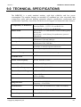
9.0
TECHNICAL SPECIFICATIONS
9-1
Models Available
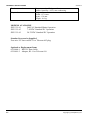
10.0 WARRANTY AND REPAIRS
10-1
Warranty Information
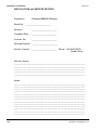
Installation and Service Record
IV
Document No 113-213-01 Rev 1.0
2008
CONTENTS
APPENDICES
Appendix A
Appendix B
Appendix C
Appendix D
Appendix E
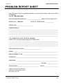
Problem Report Sheet
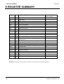
S Register Summary
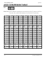
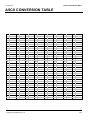
ASCII Conversion Table
Interface Connections
AT Command Set Summary
FIGURES
Figure 2.1
Figure 2.2
Figure 2.3
Figure 5.1
Figure 6.1
Figure 7.1
Figure 7.2
Figure D.1
Rear Panel Layout
DPX-213 Jumper Locations
Front Panel Layout
Telecom 604 Plug
Flow Control Buffers
Local Analog Loopback
Remote Digital Loopback
RJ-11 Connector Wiring
2-1
2-2
2-3
5-5
6-2
7-2
7-3
D-1
Front Panel Indicator Names and Functions
Valid Character Formats
CCITT and Bell Selection
Response Codes
Mode 0 Asynchronous
Mode 1 Asynchronous
Mode 2 Synchronous
Table for Converting 8 Bit Binary to Decimal
V.24 Interface Connectors
2-3
2-4
4-7
4-14
5-2
5-2
5-3
8-1
D-2
TABLES
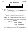
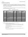
Table 2.1
Table 2.2
Table 4.1
Table 4.2
Table 5.1
Table 5.2
Table 5.3
Table 8.1
Table D.1
Document No 113-213-01 Rev 1.0
2008
V
THIS PAGE INTENTIONALLY LEFT BLANK.
VI
Document No 113-213-01 Rev 1.0
Section 1
INTRODUCTION
1.0 INTRODUCTION
Welcome to the Dataplex DPX-213. Whether you are familiar with dial network modems
or not, you will find the DPX-213 simple to operate. The modem offers advanced features
only found in quality high-end products and opens the door to a new world of data
communications. Congratulations on your purchase of the DPX-213.
1.1
Features of the DPX-213
This low power dial network and leased line data modem is designed for advanced
business and professional applications. A wide range of useful features allow many
different types of networks to be configured with the one compact unit. MNP 4 error
correction and MNP 5 data compression permit error free transmission of data at up to four
times the throughput of basic 2400 bps modems.
The DPX-213 supports five international speed standards for both synchronous and
asynchronous communications.
1.2
Requirements
To operate the DPX-213, it is assumed that the user is reasonably familiar with data
communications concepts and personal computers. If you are unfamiliar with data
communications or personal computers, please refer to the relevant texts or user manuals.
Before you can operate the modem, ensure you have the following equipment:
1. An asynchronous terminal. This can be a personal computer with an RS-232
serial port or a dumb asynchronous terminal. Once configured, synchronous
devices may be used.
2. Data communications software.
3. A DTE (Data Terminating Equipment) cable.
Copyright (C) Dataplex Pty Ltd
1-1
INTRODUCTION
1.3
Section 1
About the Manual
The manual is organised to explain increasingly more advanced operations. Novice users
should read all sections, in particular, Section 3 on modem basics and Section 7 on
Applications. The manual is divided into 12 sections as follows:
Section 1
Introduction describes the DPX-213 features and explains how to use this
manual.
Section 2
Installation explains the purpose of each indicator, switch and connector
plus how to connect your modem to the computer and telephone line.
Section 3
Before You Start covers the command method, dialling, answering,
matching dissimilar speeds, leased line and dial network operation.
Section 4
Command Set is probably the most important Section. It explains in detail
the function of each AT command for both fax and normal modem
operation.
Section 5
Applications offers some quick start information on a range of common
uses including password security, synchronous support, leased line
operation, extended character set support and remote configuration.
Section 6
Data Transfer describes advanced features such as error correction, data
compression, flow control and speed matching. This Section also gives some
warnings on set-up conflicts to be avoided.
Section 7
Testing and Diagnostics covers the loopbacks and test patterns available to
help isolate any problem in your cable, modem or phone line.
Section 8
S-Registers covers the software registers used to store the DPX-213
configuration options. Instructions are given to enable reading and altering
the S-Register values.
Section 9
Technical Specifications gives the performance specifications of the DPX213 and lists the other models available.
Section 10 Warranty and Repair allows you to record the installation configuration.
Also included is warranty information and a field service request form.
Appendices The appendices contain a problem report sheet, interface signal
leads/connections information, an ASCII code table (in decimal, binary and
hex), an S-registers summary table and the AT Command Set Summary.
1-2
Copyright (C) Dataplex Pty Ltd
Section 1
1.4
INTRODUCTION
The DPX-213 Modem
The DPX-213 is designed and built in Australia and offers:
•
•
•
•
•
•
•
•
•
•
•
•
•
Low Power: Standby current < 100uA.
Operating current < 100mA
Wake up on DTE RxD, Ring or Raise of
DTR.
Led operation link selectable.
DTR wake-up link selectable.
Alarm/Dialback function.
Password security/dialback.
Remote configuration.
Async/Sync link selectable.
Power from DB25, IDC or Power
Connector.
Small size.
MNP error correction & data compression.
Constant speed interface from 300 to 9,600
bps.
Automatic terminal speed detection from
300 to 9,600 bps.
Copyright (C) Dataplex Pty Ltd
•
•
•
•
•
•
•
•
•
•
•
•
Data operation at 300, 1200, and 2400 bps.
Auto-ranging on originate and answer at
300, 1200 and 2400 bps.
CCITT standards V.21, V.22, and V.22bis.
Bell 103 and Bell 212 support.
A rugged plastic case.
Front panel indicators.
Stored number dialling for up to ten
numbers.
DTR raise and AT command dialling.
Help screens for configuration, S-registers
and AT prompts.
Manufactured to ISO-9002/AS-3902 quality
standards.
Austel approved.
RFI compliant to AS-3458 and CISPR-22
class A.
1-3
Section 1
INTRODUCTION
THIS PAGE INTENTIONALLY LEFT BLANK.
1-4
Copyright (C) Dataplex Pty Ltd
Section 2
INSTALLATION
2.0 INSTALLATION
Read this Section in order to correctly install your modem. It includes information on
connector pinouts, front and rear panel details and a simple test of your setup.
Before operation is possible, the modem must be setup, either to the factory defaults or
with special S-register values to suit your own configuration.
Most communications software packages issue a default command string to set up the
modem. Before altering this default setup, check the software operations manual and
Section 4, Command Set.
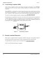
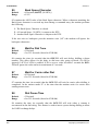
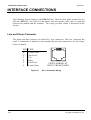
Figure 2.1
Rear Panel Layout
The rear panel of the DPX-213 has a single RJ-11 connector for line, together with a 25
Pin V.24/28 DCE connector. The supplied line cord connects from the RJ-11 of the DPX213 to the telephone wall socket. A description of the RJ-11 connectors is given in
Appendix D.
2.1
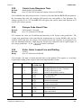
Setting the Internal Jumpers
The DPX-213 contains a number of internal jumpers which have to be set before
operation. The figure over page shows the location of the various jumpers.
Copyright (C) Dataplex Pty Ltd
2-1
Section 2
INSTALLATION
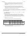
U1
RESET
Figure 2.2
2.2
DPX-213 Jumper Locations
J4:
Removing this jumper reduces current consumption by disabling the front panel
LEDs.
J5:
Removing this jumper stops the V.24 DTR input which controls the standby mode
of the DPX-213. Without this jumper set, the unit will not wake up on raise of DTR
and will not be held active by the DTR when the unit is placed in standby mode.
J8:
This jumper enables the sync clocks on the V24 interface. When Pins 1 and 2
are shorted no sync clocks will be present at the interface. When Pins 2 and 3 are
selected, both Rx and Tx sync clocks will be placed on Pins 17 and 15 of the DB25
connector.
Connecting the DPX-213 to the Telephone Line
Remove your telephone from its wall socket (you may need a flat bladed screwdriver for
this) and plug one end of the supplied cable into the socket labelled "J2 LINE" on the rear
of the DPX-213 and plug the other end into the wall socket. The terminal prompts will
give call progress indication.
NOTE: 1. Dataplex does NOT recommend the use of double adaptors to connect your
telephone in parallel with the DPX-213. Should the handset be lifted when the
modem is online, noise and errors will be injected into the data stream.
2. If the handset draws power from the telephone line (for example, to keep stored
numbers intact or to run a clock display) the battery charging current can be a
source of noise and errors in the data during long modem sessions. A long data
call may cause the telephone memory battery to discharge and lose the stored
numbers.
2-2
Copyright (C) Dataplex Pty Ltd
Section 2
2.3
INSTALLATION
Connecting a Terminal or Computer to the DPX-213
The DPX-213 uses the industry standard 25 Pin "D" connector as its data interface, with
the signals defined in the CCITT V.24, V.28 and EIA RS-232C for modems. The DPX213 operates as Data Circuit-terminating Equipment (DCE).
If you wish to connect the DPX-213 to a terminal or computer with a serial port configured
as Data Terminal Equipment (DTE), then a "straight through" cable connecting
corresponding pins of the serial ports should work. If the computer serial port is configured
as a DCE, then you must use a "cross over" or "null modem" cable. Most personal
computers and terminals have their serial interface configured for DTE operation. The
connections needed for dumb terminals, PC's and asynchronous operation are described in
Appendix D.
NOTE: When connecting the RS-232 cable to the PC, DO NOT connect the cable to the
DB25 female connector on the rear of the PC. This is the parallel port and
connection may cause damage to your PC. At the PC end, the cable should be
connected to a male connector (serial port) for correct operation.
The terminal cable to the modem should be less than 15 meters in length and restrained
with screw locks at both ends to avoid placing too much strain on the cable. Round cable is
recommended. Ribbon cables MUST be kept as short as possible to minimise clock and
data interference in the ribbon.
2.4
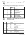
Front Panel Indicators
The front panel of the DPX-213 contains 4 LED's (Light Emitting Diodes), which are used
to indicate modem and line status.
Figure 2.3
Copyright (C) Dataplex Pty Ltd
Front Panel Layout
2-3
Section 2
INSTALLATION
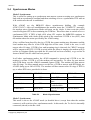
Table 2.1
2.5
Front Panel Indicator Names and Functions.
Name
Function
Colour
Status
TD
RD
CD
Transmit Data
Receive Data
Carrier Detect
Yellow
Yellow
Green
OH
Off Hook
Red
Off for mark, On for space, flickering for data
Off for mark, On for space, flickering for data
On when CD active, Off when CD inactive.
(See AT&C command)
On when modem is on line (Off hook). Off
when modem is off line (On-hook).
When the modem is in Loop modes this LED
flashes.
Testing Your Connections
With your terminal or computer connected and operating, the DTR LED should light. You
can now perform a quick test to determine if you have setup the DPX-213 correctly.
After connecting your terminal or PC to the modem, power the system up and start your
communications or terminal emulation package. To check that keyboard characters are
reaching the DPX-213, the TD LED must flash with every keystroke.
Press the K key. Each time you press the key, the TD LED should flash briefly. If no
data is reaching the DPX-213, check that:
1.
2.
3.
2.6
The correct COM port is being used on your PC;
The terminal is in the ON-LINE state and not the LOCAL Mode state, or,
The correct cable is being used and the cable pinouts are correct.
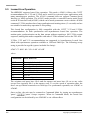
Setting Your PC for Speed and Character Format
The DPX-213 uses the attention request ('AT' prefix) to automatically detect terminal
speeds at all standard baud rates up to 9,600 baud.
For initial configuration, the terminal used must be a ten bit ASCII device operating at one
of the standard speeds, for example, 300, 1200, 2400, 4800, 9600 or 19,200 bps. The AT
command processor and Constant Speed Interface accept character formats of 10 bits in
total.
For example:
2-4
Copyright (C) Dataplex Pty Ltd
Section 2
2.7
INSTALLATION
Table 2.2
Valid Character Formats
Start Bit
Data Bits
Parity
Stop Bits
Total Bits
1
1
1
1
1
7
7
7
7
8
Mark
Even
Odd
Space
None
1
1
1
1
1
10
10
10
10
10
Making a Connection
Make sure the cable and terminal software are correct, then type atK. This allows
the modem to sense the terminal speed and calculate the parity being used. After this has
been successfully decoded, the DPX-213 will reply with:
"OK"
NOTE: If the modem fails to issue the "OK" response, and you are certain the cable,
terminal speed and parity are all correct, refer to the Section on Testing and
Diagnostics.
The DPX-213 comes with a default configuration suitable for many applications. As a
"soft" configured product, it is possible to make errors by loading a conflicting
configuration, causing unpredictable operation. If you suspect this has happened, turn the
power off, wait about ten seconds, and then turn the power back on. Force the modem back
to the factory default setup by typing at&fK.
Otherwise, type ath1K to force the modem to go Off Hook (equivalent to lifting
the handset). Typing the command line athK or ath0K will terminate
the call.
Dial a number by typing the command line: atd
(Fictitious Number Only)
1234567K.
The above command tells the modem to dial (ATD) the number 1234567. Where nonstandard dial tones are used, such as with some PABX's, the modem may not be able to
detect dial tone. In this case select the appropriate pulse or tone dialling method with the
ATDP or ATDT commands respectively and ensure the modem "blind dials" by using the
ATX0 or the ATX2 command.
When dialling a number, you should see various prompts on your terminal.
Copyright (C) Dataplex Pty Ltd
2-5
Section 2
INSTALLATION
2.8
Closing a Connection
There are several ways to abort a call. If the call has been answered by a modem and both
are on-line, typing any key will now send that character to the attached modem. Aborting
the call in this case must be done from the on-line interactive state which is entered by
typing the escape sequence of 'pause' +++ 'pause' followed by athK.
The abort timer (S-Register 7) will also abort the call if the originating modem has not
established a call before S7 times out. This is normally 45 seconds but can be between 1
and 255 seconds.
Basically, a call can be terminated in several ways :
•
•
•
•
•
Hitting any key on the terminal;
Detection of busy tone by the DPX-213;
Time-out of the modem (S-Register 7);
Loss of carrier;
Typing the escape sequence ('pause' +++ 'pause') then ath0K.
Additionally, a call will be terminated when either Busy tone (engaged) is detected or loss
of power is applied to the modem by switching off or removing the power cord.
NOTE: If data is present, then one of the Dumb modes should be used (AT*D2).
2.9
Call Establishment Sequence
The modem placing the call is termed the originating modem and the modem at the other
end is termed the answering modem. When instructed to place a call, the originating
modem will go off-hook and the OH LED will illuminate. Typically, the originating
modem listens briefly for dial tone before dialling, places the call, and then listens for
answer tone from the answering modem. If no tone is received within a preset time (stored
in S-Register 7), the call is aborted.
The originating modem is usually silent during this initial call set-up phase, but a calling
tone can be enabled (via the AT*G command) which transmits an interrupted tone so the
called party can distinguish a data call from a voice call and activate the modem if
required.
At the answering end, the modem detects the incoming ring, counts up to the preset
number of rings (stored in S-Register 0) and then goes off-hook. It transmits an answer
tone to the calling modem. Once this tone is detected by the calling modem the training
sequences begins. Therefore, it usually takes a few seconds before data transfer actually
begins.
2-6
Copyright (C) Dataplex Pty Ltd
Section 2
INSTALLATION
The called modem will turn on the ring indicator with each incoming ring (Pin 22). It will
usually output the word "RING" to the terminal with each incoming ring unless this feature
has been disabled with the ATQ or ATV commands.
The DPX-213 can be configured so it will:
•
•
•
Answer at a particular ring count (typically, the answering modem will be set
to answer on the first or second ring;
Never answer;
Answer if the data terminal ready lead (Pin 20) is asserted.
2.10 Trouble Shooting
If you are sure you have the correct cables, terminal speed and ASCII character format, but
are unable to get the OK response from typing AT, the DPX-213 may have an invalid setup string stored in the NVRAM.
A Master Reset should eliminate this problem. A Master Reset will erase all stored
numbers, passwords and configuration information. To initiate the Master Reset, turn the
DPX-213 power off, remove the lid and short the reset pads on the PCB while turning the
power back on. Wait a few seconds before removing the short
Now type atK as before. If you still experience problems, consult Section 7 on
Testing and Diagnostics or call your modem supplier for assistance. Details of the
Warranty and Service contacts are given in Section 10.
Copyright (C) Dataplex Pty Ltd
2-7
Section 2
INSTALLATION
THIS PAGE INTENTIONALLY LEFT BLANK.
2-8
Copyright (C) Dataplex Pty Ltd
Section 3
BEFORE YOU START
3.0 BEFORE YOU START
The DPX-213 is a combined soft-strapped and link selectable modem. There are number of
internal links which can be used to select Async/Sync operation, DTR wakeup and LED
operation. All other parameters are set by software commands from an attached
asynchronous terminal and then stored in Non Volatile Random Access Memory
(NVRAM). These setups or configurations are stored in 'S-registers'.
3.1
Command Structure
In general, commands entered into the modem are prefixed with 'AT' and end with a
carriage return ( K ). The modem automatically determines the terminal speed and
parity from the AT characters, loads the command into a buffer as you type it, and executes
the command when you hit the carriage return.
The factory defaults assume you are going to use the modem for asynchronous operation
on the dial network at the fastest speed the line or modem can accommodate. The character
format is assumed to be 10 bit ASCII, consisting of 1 start bit, 8 data bits and 1 or more
stop bits. For 8 to 11 bit configurations, read Section 5 on Applications and Section 8 on SRegisters.
3.2
Communications Software
The software used to configure the DPX-213 can range from simple dumb terminal
emulators to advanced communications systems. The DPX-213 is compatible with
virtually all communications software packages. If using a smart communications package,
ensure it supports the AT command set. Most packages also send an initialisation string.
This should be checked for correctness before using the modem.
3.3
Manual and Automatic Calling
Calls can be initiated by raising DTR from the terminal and typing an AT command string.
Calls can be answered by the same methods.
Copyright (C) Dataplex Pty Ltd
3-1
BEFORE YOU START
3.4
Section 3
Dial-up Line and Leased Line Support
The DPX-213 cannot share the same line as your normal telephone. It can only be used in
isolation.
NOTE: Telephones with Mode 3 connectors should not be used with this equipment.
Contact Telecom if you are trying to use the modem on a small business key
system such as a Commander, as these hand sets often signal to the PABX
electronics with non standard tones and voltages. Damage to either the PABX or
the modem could result from incorrect connection. A direct line from the local
exchange may be needed in these situations.
Leased lines are special services providing a dedicated link between two sites. No
switching is involved and hand sets are rarely provided. The DPX-213 can be configured
to operate on two wire leased lines in synchronous or asynchronous modes. Special care
has been taken with the design to ensure reliable operation in leased line mode, particularly
with line changes caused by circuit re-routing. Section 5, Applications, details the
recommended set-up strings for this use. Leased line also requires modifications to the line
connector as shown in Appendix D.
3.5
Speed Matching
There are several forms of speed matching used in the DPX-213. The autobaud feature
automatically senses the terminal speed from the typed AT commands and sets the modem
interface speed to match the terminal. The autoranging feature automatically senses the
line speed of the remote modem and adjusts to it in both originate and answer modes.
Additionally, there is a Constant Speed Interface (CSI) on the DPX-213 modem which
allows your terminal to remain at the same speed, say 9,600 bps, for all 300, 1200 or 2400
bps full duplex calls. This simplifies operation with mini-computer systems provided you
support flow control and avoids data loss if there is a speed mismatch in the system.
3.6
Flow Control
Flow control is needed whenever one device in the system runs faster or slower than
another, or there are delays in transmission while errors are corrected. Flow control can be
In-band using Xon and Xoff characters or Out-of-band using Request To Send (RTS) and
Clear To Send (CTS). These are also referred to as software handshaking or hardware
handshaking. It is legitimate to have different flow control techniques at each end of the
link. The Xon and Xoff characters are user programmable in the DPX-213 and are stored
in S-Registers 32 and 33 respectively.
3-2
Copyright (C) Dataplex Pty Ltd
Section 3
3.7
BEFORE YOU START
Escape Sequence
While off-line, the DPX-213 is in the Command State and all characters typed at your
keyboard are scanned by the command interpreter awaiting AT commands. Once on-line,
whatever is typed is sent to the remote modem. In order to get back in touch with the local
command interpreter, perhaps to hang up or to change parameters, an escape sequence
must be sent.
The industry standard "+++" escape sequence does not hang up the line or interfere with
other settings and is entered by pausing for a few seconds, typing +++, and then
pausing again. Do not press K (Carriage Return or Enter). Typing the escape sequence
returns you to the On-line Interactive State where the AT commands are active. For
example, typing athK will hang up the call.
3.8
Advanced Features
The DPX-213 has MNP-4 error correction and MNP-5 data compression software. These
are disabled in the factory defaults and must be specifically enabled if required. The
Constant Speed Interface is active by default and allows terminal speeds from 300 to 9,600
bps to be automatically supported. The modem will normally attempt to establish all calls
at 2,400 bps unless commanded otherwise or the remote modem cannot support this speed.
The modem automatically adjusts the transmit or receive speed to match the modem at the
other end of the link. The line speed of the connection is displayed as the modem goes online.
The Constant Speed Interface facility, error correction and data compression are powerful
features, but can result in problems if your terminal does not support flow control. If you
are obtaining errors, or characters are garbled or missing whenever these features are
invoked, it is likely there is a flow control problem. Check your communications software
manual, the flow control sections (see Index) and the relevant AT commands of this
manual.
To reduce the risk of unauthorised entry to your system, the DPX-213 features password
verification. A password may be stored in the DPX-213 permanently and only those calls
meeting the incoming password challenge are allowed access to the host.
The DPX-213 also contains an alarm feature that will dial a remote modem when an
external device indicates that an event has occurred. The modem will connect with the
remote modem and attempt to send a previously stored string.
Copyright (C) Dataplex Pty Ltd
3-3
Section 3
BEFORE YOU START
THIS PAGE INTENTIONALLY LEFT BLANK.
3-4
Copyright (C) Dataplex Pty Ltd
Section 4
AT COMMAND SET
4.0 AT COMMAND SET
This Section contains some useful information about entering commands into the DPX213, the 'AT' command syntax and the different operating states. The Section also contains
a complete alphabetical listing of all commands.
4.1
Command Line and Command Entry
The DPX-213 uses the common AT command set which Dataplex has extended to cover
additional features. The attention code, the letters 'AT', must precede all command lines to
the DPX-213. This code may be in either upper or lower case. The modem uses the AT
characters to detect the baud rate and character format of the incoming data. In this way,
each command line can be at a different baud rate if desired. Once the AT sequence has
been entered, the baud rate and character format are fixed for the remainder of that
command line.
Typing AT while off-line will alert the internal control processor, but while on-line, the
'pause' +++ 'pause' escape sequence must be entered.
Some AT commands act on S-Registers. These are storage locations where various
operating parameters are stored. These parameters control various modem features, such as
the number of rings to count before answering an incoming call, the delay after dialling
and before carrier detect, and so on. Refer to Section 8 for a full description of the SRegisters used in the DPX-213.
A command line to the DPX-213 consists of an attention code, one or more commands,
and a carriage return ( K ). A command line may contain up to 129 characters
(including the attention code and the carriage return). Should you enter more than 129
characters, the DPX-213 will abort the command and return an ERROR code. Re-enter the
command sequence in two smaller command lines.
Commands
may
be
concatenated
to
save
time.
For
example
at&fs0= 5d1234567K causes the DPX-213 to recall
the factory configuration, set S0=5 (answer telephone on 5th ring) and then dial 1234567.
Do not type AT more than once on any line or the AT character will be interpreted as
command and not Attention.
For example you can enter commands separately:
1.
2.
Entering atx3K will cause the modem to blind dial (not wait for dial tone).
Entering ats0=4K will cause the modem to answer on the fourth ring.
Copyright (C) Dataplex Pty Ltd
4-1
Section 4
AT COMMAND SET
3.
4.
Entering ats7=60K will cause the modem to wait 60 seconds for
carrier from the answering modem.
Entering atdn5K will cause the modem to dial the number stored in
location 5.
Or type one concatenated string:
atx3 s0=4 s7=60 dn5 K
which has the same
effect (spaces between commands are ignored and are optional).
The above command descriptions have numeric modifiers to allow selection from one of
several command options. These are usually shown as parameters 0 to 9. Where a numeric
selection is omitted, the command processor assumes a zero (0) has been entered. For
example AT*W is interpreted as AT*W0.
Commands take a variable time to execute, depending on the length of the command line
and the type of command. The DPX-213 also takes a short period (750 microseconds) after
the end of one command (the transmission of the result code) before it is ready to accept
the next command. During this time the DPX-213 is resetting its internal registers in
preparation for the next command. If communications equipment sends an 'AT' sequence
during this 750 microsecond period, the 'AT' and subsequent command will be ignored.
4.2
Attention Code Syntax
It is possible to disable the AT command sequence by using the AT*D1 (Dumb Mode)
command. In this mode, the unit will not respond to any AT sequence. The only way to
reset the unit from this state is to carry out a power up reset (if not stored in NVRAM).
A description of the syntax for entry of AT commands follows:
Carriage Return
Command lines end with the carriage return character K. The value of this character is
stored in Status register S3, and may be changed if desired. The default value of the
carriage return is ASCII code 13 {0D HEX}.
Backspace
If an incorrect entry is made in a command line before K is depressed, the backspace
key (E) can be used to erase the mistake. The backspace key will erase all characters up
to, but not including the attention code (AT). The backspace character is stored in Status
register S5. The default value is ASCII code 8.
4-2
Copyright (C) Dataplex Pty Ltd
Section 4
AT COMMAND SET
Repeat Command
When the DPX-213 is in Local Command State (waiting for an attention code), entering
the characters a/ will cause the DPX-213 to repeat the last command line. The 'A'
character can be in either upper or lower case. If an a/ is entered directly after turning
on the power, the modem will return an ERROR code.
Command Parameters
Most commands to the DPX-213 have several parameters. These parameters select the
various options for each command. Should the parameter be missing for a particular
command, the modem will substitute the value 0. Should a parameter be outside the
defined range, the modem will return an ERROR code.
Result Codes
After the DPX-213 has executed each command line, it returns a result code to show the
status of the command. The result is in the form of digits (0 to 233) or text. Results
displayed in digit format are often used when the modem is being controlled by a
computer. Results displayed in the text format are suited to terminal control. Result codes
can be disabled by setting Quiet Mode (ATQ1).
Status Registers
Configurations are stored in the Status Registers, called 'S-registers'. The DPX-213 has 24
Status Registers (of which, some are reserved for future expansion or used to maintain
compatibility with the DPX-224). Most commands in the DPX-213 alter values in the
status registers.
4.3
DPX-213 Operating States
There are four distinct operating states for the DPX-213:
1.
2.
3.
4.
Idle State
Command State
Data State
On-line command State
A description of each operating states follows.
Copyright (C) Dataplex Pty Ltd
4-3
AT COMMAND SET
1.
Section 4
Idle State
This state is entered shortly after power is applied to the modem and the power-up
self test has been passed. It can also be entered after the modem has executed a nondialling command line. In this state, the modem is waiting to autobaud an AT
sequence from the DTE or awaiting a ringing signal from the telephone line. If a
valid 'AT' entry is detected, the modem enters the Command State.
If a valid ringing signal is detected the modem will send a RING message to the
DTE at the last autobaud speed. If set to answer (S-Register 0 not set to 0) the
modem will go off-hook and enter the Data State after a predetermined number of
rings (S0).
2.
Command State
During the Command State, the modem buffers command characters from the DTE
until a carriage return ( K ) character is received. The modem will buffer up to
48 characters not including the initial 'AT' characters. If more than 48 characters are
received the modem will insert a carriage return character and return an ERROR
message signifying buffer overflow. If no overflow is detected and a carriage return
character is received the modem will start to sequentially execute commands in the
buffer until one of the following:
1. Carriage Return Detected
If this is part of a dial command, the DPX-213 will execute the following
sequence: go off-hook, look for dial tone (unless set to blind dial) and then
proceed to place the call.
2. Illegal Command Encountered
The modem will execute the following sequence: send an ERROR message to
DTE, empty the command buffer and return to idle state.
3. Answer (ATA) or On-line (ATO) Command Received
The modem will enter the Data State.
4-4
Copyright (C) Dataplex Pty Ltd
Section 4
3.
AT COMMAND SET
Data State
After an ATA (Answer) or ATO (Originate) command, the modem enters the Data
State. The modem will attempt to handshake with the remote modem or if already
connected will enter begin to exchange data.
The normal Data State is transparent and all characters issued by the DTE are
passed to the remote end. Sometimes you may need to abort the operation and
regain control of the local modem instead of the remote DTE. This is possible in the
On-line Command State and is selected with the escape sequence.
Several other interface or line events that will cause the modem to drop out of
transparent data transmission (Data State) to local control (On-line Command State)
are described as follows:
1. Escape Sequence Detected ('pause' +++ 'pause')
The modem will leave the data state and execute the following sequence: send
an "OK" message to the DTE, clamp transmit data to mark, disable receive data
to DTE and enter the On-line Command State.
2. Loss of Carrier Detected (provided S10 is not set to 255)
The modem will execute the following sequence: send a "NO CARRIER"
message to the DTE, go on-hook and returns to Idle State.
3. DTR Dropped (provided DTR is not forced on and AT&Dn is set)
The modem will execute the following sequence: send a "NO CARRIER"
message to the DTE, go on-hook and return to Idle State.
4. DTR Dropped (provided DTR is not forced on and AT&D2 or AT&D3 is set)
The modem will execute the following sequence: send a 'NO CARRIER'
message to the DTE, go on-hook and return to Idle State.
Copyright (C) Dataplex Pty Ltd
4-5
AT COMMAND SET
4.
Section 4
On-line Command State
This state is entered after a 'pause' +++ 'pause' escape sequence has been
detected. The modem link is preserved and the user communicates with the local
modem and not the remote DPX-213. All data sent by the remote modem is ignored
but carrier is still monitored and the message "NO CARRIER" will be issued if loss
of carrier is detected. Additionally, some RTS, DTR, or make busy control changes
are acted upon. Any normal command that can be issued in command state can now
be issued in the On-line Command State while a call is active. However, some
commands have no meaning such as ATA, and will return ERROR. The most
common use of the On-line Command State is to issue the ATH command to hang
up the call. Other options to exit the On-line Command State are:
1. ATH Command Received
The modem will execute the following sequence: send an "OK" message to the
DTE, go on-hook (hang-up) and return to Idle State.
2. ATZ Command Received
The modem will execute the following sequence: reset the configuration to the
customer stored value, go on-hook (hang-up), send an "OK" message to the
DTE and return to Idle State.
3. ATO Command Received
The modem will execute the following sequence: send a "CONNECT"
message, unclamp received and transmitted data, and returns to the Data State.
4.4
AT Command Set
The remainder of this Section contains an alphabetical listing of all commands, including
full syntax and details of use. For each command, parameters, default settings (or AT&F)
and the Status Register (S-register) bits that store the present command setting are
provided. If the value in a status register effects the operation of a command, the register
with its default value is shown. For example: S7 (45 seconds).
4-6
Copyright (C) Dataplex Pty Ltd
Section 4
AT COMMAND SET
A/
Repeat Last Command
Parameters : None
Default
: None
A/ is the only command that must not be preceded by an "AT" or terminated with a
carriage return ( K ). This command will repeat the preceding command string. This is
useful for redialling a previously engaged phone number.
ATA
ANSWER
Parameters : None
Default
: None
Causes the modem to answer an incoming call (go off-hook), try to train on the incoming
signal and then go on-line. There will be a 2.1 second delay to pass STD beeps, billing
meter pulses and the modem's answer tone. If the modem fails to detect carrier within the
time stored in register S7 (45 seconds), the modem will go on-hook and return to Local
Command State. The modem ignores all commands in a command line following the
Answer command.
ATB
BELL/CCITT Select
Parameters : 0 or 1
Default
: 0 (CCITT Modulation)
This command selects CCITT or BELL modulation format for signaling to line. In
conjunction with the ATFn command, the user can force the line speed and modulation to a
predetermined format instead of relying on the autoranging capabilities of the DPX-213.
The command is useful when placing international calls to Bell modems. Refer to the ATF
command description for full details on autoranging and other settings. The Bell 103 Mode
is only available when the Constant Speed Interface is disabled via the AT&I0 command.
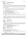
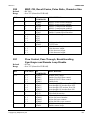
Table 4.1
CCITT and Bell Selection
SPEED
300
1200/75
1200
2400
ATB0
ATB1
ATF1
V.21
Bell 103
ATF3
V.23
V.23
ATF4
V.22
Bell 212
ATF5
V.22bis
V.22bis
Copyright (C) Dataplex Pty Ltd
CCITT
Bell
4-7
Section 4
AT COMMAND SET
ATD
DIAL
Parameters : Dial String
Default
: None
Causes the modem to go off hook and originate a telephone call. After dialling, the modem
will wait for an answer tone from the remote modem, try to train on the incoming signal,
and go online. If the modem fails to detect an answer tone after the time in register S7 (45
seconds), the modem will return to the Local Command State and send the "NO
ANSWER" message.
The modem will dial all 10 pulse digits or 12 standard tone pairs. These digits may be
separated by spaces. Certain modifiers will effect the way the number is dialled and are
listed below. The dial string consists of telephone number digits and dial modifiers.
Acceptable dial digits are the numbers 0-9 (zero through to nine) and the symbols * # (for
tone dialling only). Acceptable dial modifiers are Nn P T and , (comma).
The DPX-213 ignores any other characters in the dial command. These can be freely used
to improve readability. atd1234567K is equivalent to:
atd (03) 123-4567K.
Entering the dial string with no parameters causes the modem to try to establish a
connection without dialling any digits. This can be used in leased line Mode in conjunction
with the Answer command to make a connection.
Dial Modifiers
Dial modifiers are used with the dial command to instruct the modem to perform different
dialling features. They can be placed anywhere in the dial string.
Nn
P
T
,
Dial stored number where n = 0 to 9.
Set pulse dialling.
Set tone dialling.
Pause for time in status register S8 (Default = 2).
Nn - Dial Stored Number
The ATDN command, followed by a number from 0 to 9 instructs the modem to dial the
number stored in that memory location. The numbers are stored into the memory locations
by the AT&Z command. AT&N will display all 10 stored numbers. If n = 0 or no number is
given, the modem dials the number in location N1.
4-8
Copyright (C) Dataplex Pty Ltd
Section 4
AT COMMAND SET
P - Set Pulse Dialling
Normally the DPX-213 will automatically sense whether to use tone or pulse dialling.
Using this modifier causes any further digits in the dial string and if ATX3 is set, dial
commands, to be dialled with decadic pulses. Thus, pulse and tone dialling may be mixed
in the same telephone number. The default setting is for check for tone dialling. If ATX4
(check for dial tone) is set, the DPX-213 will dial the first digit of a dial string in tone
mode and recheck for dial tone. If dial tone is still present, the entire number will be
dialled in pulse mode, otherwise, the rest of the number will be dialled in tone mode.
T - Set Tone Dialling
Causes any further digits in the dial string (provided ATX3 is set) or dial commands to be
dialled with DTMF tones. Pulse and tone dialling may be mixed in the same telephone
number. If ATX4 (check for dial tone) is set, the DPX-213 will dial the first digit of a dial
string in tone mode and recheck for dial tone. If dial tone is still present, the entire number
will be dialled in pulse mode, otherwise the rest of the number will be dialled in tone
mode. A 'T' or 'P' command in a dial string will override the automatic tone/pulse selection.
, (comma) - Pause
Causes the modem to wait for the time in register S8 (2 seconds) before continuing.
Sometimes used after dialling the STD codes before dialling the rest of the telephone
number. For example: atd03,1234567K.
ATDn
DIAL Stored Number
Parameters : 0 to 9
Default
: 0 (act on Number in location zero)
The ATDNn command causes the DPX-213 to go off-hook and dial the number stored in
location n. It is equivalent to typing ATD followed by the valid dialling characters stored in
location n.
ATE
Command ECHO
Parameters : 0 or 1
Default
: 1 (Echo Enabled)
The ATE command controls the echoing of characters from the DTE in local command
state.
ATE0 - Disable Local Echo.
ATE1 - Enable Local Echo. The modem echoes all characters from the local DTE.
Copyright (C) Dataplex Pty Ltd
4-9
Section 4
AT COMMAND SET
ATF
FORCE Line Speed
Parameters : 0 to 6
Default
: 0 (Auto Speed)
This command lets you select the transmission speed and modulation format independent
of the DTE interface speed. Use this command in conjunction with the ATB command.
This allows you to go on-line at 300, 1200 or 2400 bps but keep your terminal speed fixed
at some other speed.
ATF0 - Modem autoranges for both originate and answer. The Constant Speed Interface
operates from 300 to 9,600 bps. The DPX-213 will accept incoming calls at
300,1200 or 2400 bps.
ATF1 - Selects 300 bps. CCITT or Bell selected by ATB.
ATF2 - Not used. Responds with ERROR.
ATF3 - Not used. Responds with ERROR.
ATF4 - Selects V.22 or Bell 212A 1200. Speed fixed at 1200 bps.
ATF5 - Selects V.22bis. Speed fixed at 2400 bps.
ATF6 - Similar to ATF0 except that once a connection is established, forces DTE speed to
line.
The DPX-213 will autorange on both answer or originate. Set ATF0 at the answering
modem and it will adjust speed automatically to accommodate the incoming call. If the
Constant Speed Interface (AT&I1) is set, the DTE speed will be the last autobaud speed
(except when ATF6 is used).
ATH
HOOK Control
Parameters : 0 or 1
Default
: 0 (modem On-hook)
Controls the hook relay, connecting and disconnecting the modem from the telephone line.
ATH with no numeric suffix is interpreted as ATH0 and causes the modem to hang up (go
on-hook) and return to the Idle State.
ATH0 - Forces the modem to go on-hook and return to Idle State.
ATH1 - Forces the modem to go off-hook (on-line).
ATI
IDENTIFICATION
Parameters : 0 to 3
Default
: 0 (Display "DPX-213")
Returns the modem identification codes to your terminal.
ATI0 - Return modem product code. The DPX-213 sends "DPX-213".
ATI1 - Return ROM checksum.
ATI2 - Return result of checksum verification. The DPX-213 sends "OK" if the checksum
verifies.
ATI3 - Return software revision number.
4-10
Copyright (C) Dataplex Pty Ltd
Section 4
AT COMMAND SET
ATNn&Z
Store String in NVRAM
Parameters : 0 to 9
Default
: None
This command allows up to 44 characters to be stored in each of the ten NVRAM locations
for later recall.
NOTE: Location zero and location one are the ONLY locations that can be dialled on the
rise of DTR.
Locations may hold Alarm Mode text strings (2,3,4), Passwords (5,6,7,8,), numbers to dial
on the raise of DTR (0,1) and number to dial with the ATDNn command for security
callback after a password match (any location). For example:
LOCATION
CONTENTS
0
1
2
3
4
5
6
7
8
9
DTR / n0 Dial Number.
Alternate DTR / n1 Dial Number
Alarm Mode Connect String / n2 Dial Number
DTR Raised String / n3 Dial Number
Keyboard Activity Alarm String / n4 Dial Number
Password Storage / n5 Dial Number
Password Storage / n6 Dial Number
Password Storage / n7 Dial Number
Password Storage / n8 Dial Number
Password String / n9 Dial Number
When a stored number is recalled via the ATDNn command, the command processor
effectively enters ATD, fetches location n and then dials the digits in the order it finds
them.
ATO
On-line, ORIGINATE and Retrain
Parameters : 0
Default
:0
If the modem is already online, this command causes the modem to return to the Data
Transfer State. If the modem is not online, the modem will attempt to originate a call (go
off hook and wait for answer tone). The modem ignores all commands in a command line
following the Originate command.
ATO0 - Return to On-line State or originate a call.
Copyright (C) Dataplex Pty Ltd
4-11
Section 4
AT COMMAND SET
ATP
Set PULSE Dialling
Parameters : None
Default
: None
If ATX3 (do not listen for dial tone) is set, ATP causes the DPX-213 to dial any further dial
commands with decadic pulses. If ATX4 (check for dial tone) is set, then regardless of the
state of the ATP command, the DPX-213 will dial the first digit of a dial string in tone
mode and recheck for dial tone. If dial tone is still present, the entire number will be
dialled in pulse mode, otherwise the rest of the number will be dialled in tone mode.
ATQ
QUIET Mode
Parameters : 0 or 1
Default
: 0 (Enable dialling messages)
This command controls whether or not the modem sends messages and result codes (such
as "OK") to the DTE as it executes commands (some software packages may not recognise
call progress messages); the AT command itself will still be echoed (unless ATE0 is
active).
ATQ0 - Enables command and call progress messages to be sent to the DTE.
ATQ1 - Enables Quiet Mode and ensures no messages are passed during call placement.
When ATQ1 is in use, sufficient time must be allowed for each command issued to
be executed or closely spaced commands may be misinterpreted by the modem.
ATSr?
Read STATUS Register Contents
Parameters : r = 0 to 53
Default
: 0 (Display Register 0)
This command will return a three digit decimal value of the selected S register, r. The
display is always in decimal, even for bit mapped registers.
4-12
Copyright (C) Dataplex Pty Ltd
Section 4
ATSr=n
AT COMMAND SET
Set STATUS Register Contents
Parameters : r = 0 to 53, n = 0 to 255.
Default
: r = 0, n = 0
The ATSr=n command allows the user to change the modem configuration parameters by
altering the values stored in the S registers. You must first convert a binary bit mapped
register into decimal before attempting to set it. Use the S register descriptions and
Appendix B to get the correct bit number. This command should be used with care, as
loading incorrect results into the S registers can produce unpredictable results. Type
at&fK to reload the factory default settings if the S registers become corrupted.
ATT
Set TONE Dialling
Parameters : None
Default
: None
This command enters the tone dial mode and awaits the next ATDnnnn command. Typing
attK is a valid entry. Additionally, typing 'T' within a dial string such as the
following command string: atdt 1234567K is acceptable. This
command overrides the automatic tone/pulse dialling selection only when used as a dial
modifier.
ATV
Set VERBOSE Response Codes
Parameters : 0 or 1
Default
: 1 (Verbose Mode)
Determines whether the DPX-213 returns result codes from commands to the DTE in text
format or digit/numerical format (Verbose or Terse). Most communications programs use
digit responses to determine command status.
ATV0 - Selects digit (terse) responses; digit code is followed by a carriage return.
ATV1 - Selects verbose or text responses; word code is preceded and followed by a
carriage return character (S-register 3) and a line feed character (S-register 4).
Copyright (C) Dataplex Pty Ltd
4-13
Section 4
AT COMMAND SET
ATX
Call Progress Control
Parameters : 0 to 3
Default
:3
The ATX command controls the level of call progress detection when originating or
answering a telephone call. The table on the following page shows the result codes
returned.
ATX0 - Enables response codes 0-4, 8, 12-14 modem will blind dial.
ATX1 - Enables response codes 0-4, 6-8, 12-14 modem needs dial tone.
ATX2 - Enables response codes 0-5, 8-10, 12-21 modem needs dial tone.
ATX3 - Enables response codes 0-10, 12-21 modem will blind dial.
The term 'blind dialling' refers dialing without trying to detect a dial tone. This is useful
when the dial tone is a low level or non-standard dial tone as found with some PABX's.
The auto tone or pulse dial detection feature of the DPX-213 is only enabled when the
modem is not blind dialling and when it is configured to detect dial tone.
The available response codes that are selected by the ATXn command are shown below.
Table 4.2
4-14
Response Codes
Digit
Code
Description
0
1
2
3
4
5
6
7
8
10
11
12
13
14
16
17
18
19
20
21
OK
CONNECT
RING
NO CARRIER
ERROR
CONNECT 1200
NO DIAL TONE
BUSY
NO ANSWER
CONNECT 2400
Command executed without error.
Modem connected at any speed if ATX0 enabled.
Incoming call detected.
Carrier not detected after S7 timeout or carrier lost.
Illegal command or buffer overflow.
Modem connected at 1200 bps.
Dial tone not detected.
Busy signal detected, call aborted.
Remote did not answer.
Modem connected at 2400 bps.
Reserved
Local or remote modem in loop.
Remote modem has refused RDL request.
Local modem has accepted RDL request.
Modem connected at 1200 MNP 2-5.
Modem connected at 2400 MNP 2-5.
Local or remote modem in loop with MNP.
Modem connected at 1200 MNP 2-4.
Modem connected at 2400 MNP 2-4.
Connection attempt aborted by operator.
LOOP GRANTED
RDL DENIED
RDL ACCEPTED
CONNECT 1200/REL
CONNECT 2400/REL
LOOP GRANTED/REL
CONNECT 1200/REL
CONNECT 2400/REL
ABORTED
Copyright (C) Dataplex Pty Ltd
Section 4
ATZ
AT COMMAND SET
Modem Reset
Parameters : 0,1
Default
: None
Entering ATZ0 resets the modem and copies the user stored NVRAM configuration to the
active RAM. It restores all user controlled settings to previously stored values. If the
NVRAM contains an invalid configuration, typing ATZ will merely copy the bad data
from NVRAM to active RAM. You must use AT&F (load factory configuration from
ROM to RAM) followed by AT&W (write RAM configuration to NVRAM) to recover
from this.
If the modem is in the On-line Command State this command will terminate the call and
the modem will return to the Idle State after the command is processed. See also the AT&F
command which copies the factory defaults from ROM into the active RAM.
If ATZ1 is entered, the unit will be placed in the very low power standby mode (depending
upon DTR level and setting of jumper J5). The modem may be woken from this state by
either raising the DTR, activity on DTE Txd, Ring detection or power cycle. When the
modem is in standby mode the unit is effectively switched off. If a unit is on line the
connection will be lost.
AT&C
CARRIER Detect Control
Parameters : 0 or 1
Default
: 0 (CD Pin 8 always High)
This command controls the status of both the CD lead (Pin 8) in the V.24/RS-232 interface
and the front panel CD LED.
AT&C0 - V.24 Pin 8 CD and LED always forced on.
AT&C1 - V.24 Pin 8 CD and LED follows phone line data carrier.
AT&D
DTR Control
Parameters : 0 to 3
Default
: 0 (DTR Always On)
This command controls events on the fall of DTR (Data Terminal Ready). See the AT&M
command for interactions on the rise of DTR. When this command is enabled, the DTR
lead must be high for the modem to operate correctly.
AT&D0 - DTR input ignored.
AT&D1 - Modem set to Command State when DTR drops (as for escape sequence).
AT&D2 - Modem set to on-hook and returns to Command State when DTR drops
(ATH).
AT&D3 - Modem initializes (executes ATZ) when DTR falls.
Copyright (C) Dataplex Pty Ltd
4-15
Section 4
AT COMMAND SET
AT&E
ERROR Correction
Parameters : 0 or 1
Default
: 0 (MNP disabled)
AT&En enables or disables error correction and data compression in the DPX-213. When
used with the AT&I1 Constant Speed Interface command, the terminal can operate at 4800
bps to 9,600 bps to take full advantage of data compression. Error control or data
compression is not supported at V.21 (300 bps) speeds and in one of the two leased line
modes.
AT&E0 - Error control/data compression disabled.
AT&E1 - MNP-2 to MNP-4 error correction enabled. The highest level automatically
negotiated by modems. If no remote MNP is found, the modem will fall back to
Constant Speed Interface mode or disconnect if AT&I0 is set.
When MNP modems connect, one of the modems must send a request packet (MNP) to
initiate the negotiation. By convention, this is normally the originating modem. If the
modem is connected to a non MNP modem this request will appear as corrupt characters to
the DTE on the non MNP modem. Therefore, the default setting is MNP off.
NOTE: If MNP is to be used, both modems must support it and at least one modem must
request it.
AT&F
Load FACTORY Configuration
Parameters : None
Default
: None
This command copies the factory defaults from fixed EPROM into working RAM. This is
useful for restoring the modem to a preset configuration. To use the factory defaults in
normal operation, type at&fK then make them permanent by typing
at&wK.
AT&G
GUARD Tone Control
Parameters : 0 or 1
Default
: 0 (no Guard Tone)
Guard tone is typically used to disable echo cancellers within the U.K. It is only active in
1200 bps and 2400 bps operation. The modem sends guard tone to line to disable echo
suppressors. Echo suppressors are desirable for voice lines where one party talks and the
other listens, but undesirable for full duplex data lines where both ends are transmitting
simultaneously. Echo suppressors are rarely used in Australia. Guard tones are only active
when operating in V.22bis mode, and only on the answering modem.
AT&G0 - No Guard Tone.
AT&G1 - 1800Hz or 550Hz Guard Tone (depends on Bell setting, ATB0 enables 1800Hz).
4-16
Copyright (C) Dataplex Pty Ltd
Section 4
AT&H
AT COMMAND SET
HELP
Parameters : 0 to 4
Default
: None
This command displays several levels of help screens to reduce the need for a handbook to
enter field changes.
AT&H0 - General help Summary.
AT&H1 - Extended help Summary.
AT&H2 - Help on Dial Modifiers.
AT&H3 - Help on Test Commands.
AT&H4 - Help on S-Registers.
AT&I Constant Speed INTERFACE
Parameters : 0 or 1
Default
: 1 (enable Constant Speed Interface)
The AT&I command allows the data rate of the DTE to be at a uniform rate, regardless of
the rate determined by the communication format (specified by ATFn). This is useful if the
DTE can only operate at a single speed and when error correction is enabled. It can also
control whether a connection will be established or rejected if the MNP negotiations fail.
AT&I0 - Disable Constant Speed Interface. The modem will autobaud on the DTE rate
before the call, but will change the interface speed to that of the actual line
connection as soon as the call is established. For example, if your terminal is set
for 2400 bps and the DPX-213 can only establish a link at 1200 bps, the
message "CONNECT 1200" will be displayed at the 2400 bps autobaud rate and
then the interface will change to 1200 bps. Therefore, the terminal speed must be
changed to continue without errors. Some communications packages read the
"CONNECT XXXX" message and can be instructed to change your DTE speed
automatically. Also, the 'pause' +++ 'pause' escape sequence will need to
be sent at 1200 bps to be recognised.
AT&I1 - Enable Constant Speed Interface. The data to and from the terminal will be at the
last autobaud speed regardless of the actual connection speed. DTE speeds above
2400 bps (or faster than the actual on-line rate) can cause data to enter the
modem faster than it can be sent to line. Therefore, unless the AT&K and AT&U
flow control commands are set, data may be lost in buffer overflows.
The AT&I1 command in conjunction with AT&E1 or AT&E2 (MNP-4 or MNP-5) ensures
a dial link will be established regardless of whether or not the remote modem can support
MNP.
Copyright (C) Dataplex Pty Ltd
4-17
Section 4
AT COMMAND SET
AT&K
DTE Flow Control
Parameters : 0 to 3
Default
: 1 (Select Xon/Xoff Flow Control)
This command selects the method of handshaking between the DTE and the modem during
error correction, data compression or whenever the Constant Speed Interface is set at a
different rate to the line speed.
NOTE: Xon/Xoff flow control should NOT be used when passing binary, command or
executable files since they may contain Xoff characters without matching Xon
characters. The modem may appear to 'lock up' and Xoff characters may be
introduced or lost, thus corrupting the file. Use hardware flow control (RTS/CTS)
for binary file transfers.
AT&K0 - Disable flow control. The DTE must be careful not to overflow the buffers or
data will be lost.
AT&K1 - Xon/Xoff ( ###q / ###s ) enabled. The modem can control the flow of
data by issuing an Xoff to the DTE. The Xon and Xoff characters can be altered
from their defaults and are stored in locations S33 and S32 respectively. Both
the modem and the DTE must halt whenever they receive an Xoff character and
not restart until they receive an Xon character.
AT&K2 - Enables RTS/CTS hardware flow control. When set, the modem drops Clear To
Send (CTS) whenever the buffers are almost full. The DTE may also flow
control the modem by dropping RTS.
AT&K3 - Enables both RTS/CTS and Xon/Xoff flow control. This is equivalent to
issuing the commands AT&K1 and AT&K2. Be sure to terminate RTS and CTS
correctly when using this command.
NOTE: Whenever AT&K2 or 3 are invoked, the RTS and CTS leads must be correctly
driven and not left floating in the interface cable.
4-18
Copyright (C) Dataplex Pty Ltd
Section 4
AT COMMAND SET
AT&L
LEASED Line Select
Parameters : 0 or 1
Default
: 0 (Dial Network)
The CCITT V.22bis recommendation is primarily concerned with dial network operation.
Leased line operation with different manufacturers products may not be entirely
successful. The DPX-213 supports leased line operation at 1200 and 2400 bps in both
AT&L0 and AT&L1 modes. Data transfer at 300 bps is only supported in AT&L1 mode and
data transfer at 1200/75 V.23 is not supported in either leased line mode.
AT&L0 - Dial Network Mode.
AT&L1 - Enable speeds 300, 1200 and 2400 bps only. MNP/V42 and the Constant Speed
Interface are disabled in this Mode. Synchronous or Asynchronous Mode is
selected via the AT&Mn commands. The AT&D0 (ignore DTR) effectively
overrides the DTR Pin on the interface. Setting AT&D0 with AT&L1 forces the
DPX-213 on-line immediately regardless of the DTR status. This is the
recommended mode for interworking with the DPX-224 or TEL-424 modems.
Configure the modem for leased line operation as follows:
1.
2.
3.
4.
5.
6.
Set AT&D1 mode.
Issue the AT&L1 command to select Leased Line Mode.
Set register S0=0 at one end to force Originate Mode.
Set register S0=1 at the other end to force Answer Mode.
Enter AT&M1 mode.
Raise DTR at both ends to establish the link.
Once connected the escape sequence 'pause' +++ 'pause' is entered, control may be
regained and allow entering the ATH command if needed. Alternatively, the DTR may be
dropped to return to Command Mode. In synchronous (AT&M2 or AT&M1) Mode,
dropping DTR will terminate the call. In asynchronous (AT&M3) Mode, dropping DTR
will follow the AT&Dn command.
All keystrokes are ignored during leased line call establishment phase.
NOTE: The line interface cable must be modified as shown in Appendix D for correct
operation in leased line modes.
Copyright (C) Dataplex Pty Ltd
4-19
Section 4
AT COMMAND SET
AT&M
Synchronous/Asynchronous MODE Selection
Parameters : 0 to 3
Default
: 0 (Async)
The AT&M command selects asynchronous or synchronous terminal modes of operation.
This command also provides for the manual and automatic dialling of a stored number
under DTR control. See the AT&D command for actions taken on the fall of DTR.
AT&M0 - Asynchronous Mode 0. Type ATDnnn to dial.
AT&M1 - Synchronous Mode 1. DTR dial asynchronous. Enabling this Mode will cause
the modem to dial the number in location zero on raise of DTR. AT&Dn must
be correct.
AT&M2 - Synchronous Mode 2 (with asynchronous terminal dialling). Use an
asynchronous terminal to place the call and then change to Synchronous Mode
once the call is placed.
AT&M3 - Synchronous Mode 3. DTR dial synchronous. Enabling this mode will cause
the modem to dial the number stored in location zero on raise of DTR.
AT&N
Display/Clear Dialling Directory
Parameters : None or 99
Default
: None
AT&N will display the 10 telephone number storage locations with their contents. Any
numbers which require alteration can be updated individually with the ATNn&Z command.
The AT&N99 command erases all 10 locations.
AT&P
PULSE Dial Make/Break Ratio
Parameters : 0,1
Default
: 1 (CCITT Make/Break Ratio)
This command allows the user to select the pulse dialling make to break ratio.
AT&PO - Bell Make/Break Ratio (US setting).
AT&P1 - CCITT Make/Break Ratio (Australian setting).
4-20
Copyright (C) Dataplex Pty Ltd
Section 4
AT&T
AT COMMAND SET
TEST Modes
Parameters : 0 to 6
Default
: 0 (No Tests in Progress)
This command enables and disables several local and remote loopback tests, and tests with
the internal test pattern generator.
AT&T0 - Terminate test in progress.
AT&T1 - Initiate Local Analog Loopback.
AT&T4 - Enable Remote Digital Loopback response.
AT&T5 - Disable Remote Digital Loopback response.
AT&T6 - Initiate Remote Digital Loopback
AT&U
USER Flow Control
Parameters : 0 to 3
Default
: 0 (Flow Control off)
This command affects flow control in the modem. AT&Un is only active while MNP /V42
is disabled and while the Constant Speed Interface is enabled. If MNP/V42 is enabled then
AT&U can remain at the defaults. Refer to the Data Transfer Section (Section 6) for more
details. The commands AT&En, AT&Kn, AT&In and AT&Un all influence flow control and
must be correctly set for your application.
Whenever AT&Un is invoked, Xon/Xoff characters may be inserted in the data stream and
corrupt a binary file transfer. Alternately, an Xoff character encountered in a binary file
transfer will halt the modem. Select AT&U0 (off) for binary file transfers.
AT&U0 - Pass through off, line flow control off.
AT&U1 - Pass through enabled, line flow control off.
If Xon/Xoff flow control is active (AT&K1 or AT&K3), Xon/Xoff characters
through from the DTE to the line side buffers of the modem - after being acted
upon.
AT&U2 - Pass through off, line flow control on.
This selection is only valid if RTS/CTS handshaking (AT&K2) is selected. In
this mode, any flow control characters detected in the data received from line
will be acted upon by the line buffer but not passed to the DTE buffer.
AT&U3 - pass through on, line flow control on.
This selection is usually used with DTE flow control set to RTS/CTS, AT&K2.
Flow control characters received at the line buffer will be acted upon and then
passed to the DTE via the DTE buffer. The DTE will be operating in a mode
that enables it to respond to both RTS/CTS and Xon/off flow control. In this
way both the local modem and the remote DTE may flow control the far modem
and DTE.
Copyright (C) Dataplex Pty Ltd
4-21
Section 4
AT COMMAND SET
Pass through means that, if Xon/Xoff flow control is enabled, the controlling character
detected will be acted upon by any buffer it encounters, and then passed through to the
next buffer in the link. Disabling pass through means that any Xoff character received by a
buffer will be obeyed but the Xoff character will then be discarded. If line flow control is
enabled, the receiving modem line buffers will be susceptible to flow control characters in
the received data stream.
AT&W
WRITE Active Configuration to NVRAM
Parameters : None
Default
: None
Whenever power is applied to the DPX-213, or the modem is reset (ATZ), the status
registers are loaded with values saved in the non volatile RAM. AT&W allows a particular
configuration to be saved in the non volatile RAM and then reloaded the next time power
is applied to the modem or the reset (ATZ) command is issued. The interface speed is also
saved and becomes the default speed for the subsequent incoming calls (and after power
cycling).
AT&Z
Store Telephone Number
Parameters : Dial String
Default
: N/A
This command stores a dial string in non volatile RAM for dialling later with the ATDNn
command. Any valid dial string (see the ATD command) can be stored and up to a
maximum length of 36 characters. Any characters after this will be ignored. The storage
location to be overwritten by the AT&Z command is set by the ATN command.
To invoke the dial string type atdnK with no other characters. Dialling by pulse
or tone dial will be by the default or the last used method. The more general storage/access
command is ATNn&Z, which gives access to all 10 storage locations.
4-22
Copyright (C) Dataplex Pty Ltd
Section 4
AT COMMAND SET
AT*A Alarm/Alert Mode
Parameters : 0 to 3
Default
: 0 (Alarm off)
This command enables the Alarm function on the DPX-213.
AT*A0 - Alarm function disabled.
AT*A1 - Enabling this command will cause the modem to dial the number stored in
location 0 upon "wake up". When connected, the modem will send the string
stored in location 1. If the modem is woken by DTR, it will send the string stored
in location 2; if woken by TxD, it will send the string stored in location 2 and if
woken by Ring, the modem will ignore ring and then dial and send strings in
locations 1 and 4 respectively.
AT*A2 - The modem will "wake up" on any Ring, raise of DTR or TxD from DTE. By
invoking the AT&M command, the unit will dial the number stored in location 0
on rise of DTR and send the relevant alarm string on connection. Otherwise, the
modem will wait for an AT command or Answer when the ring limit is reached.
If the AT command originates the call then the alarm string is sent on call
connection, however, if the modem has answered the call then no alarm string is
sent.
AT*A3 - Reserved for future use.
See applications section for full description of this function.
AT*C Configuration Status
Parameters : None
Default
: None
The AT*C command will display the active modem configuration. The table below shows
the default (AT&F) configuration.
CONFIGURATION
STATUS
CONFIGURATION
STATUS
B Bell/CCITT
E Echo
F Format
T/P Tone or Pulse
X Result Code
&C DCD Option
&D DTR Option
&E Error Control
&G Guard Tone
&I Constant Speed
&K DTE Flow Control
&L Leased Line
0
1
0
0
3
0
0
0
0
1
1
0
&M Sync/Async
&P Pulse Ratio
&T RDLB Enable
&U DCE Flow Control
*A Alarm Mode
*D Dumb Mode
*E Compression
*G Calling Tone
*P Password
*R Remote configuration
*Y Break Handling
0
1
0
0
0
0
0
0
0
0
0
Copyright (C) Dataplex Pty Ltd
4-23
Section 4
AT COMMAND SET
AT*D DUMB Mode
Parameters : 0 to 3
Default
: 0 (Disabled)
To prevent modem "lock up", it is advised that the escape sequence 'pause' +++
'pause' be disabled when using the Dumb Mode (see Register S2 description for more
details).
AT*D0 - Allows the DPX-213 to respond to normal AT command and attention sequences.
AT*D1 - Disables AT command acceptance and echo. Once the modem is configured, AT
commands can no longer gain control of the DPX-213. The modem will still
abort connect sequence if a key is pressed during the training sequence.
AT*D2 - Disables call placement abort on DTE activity. If characters are sent to the
modem during call connect sequence the modem will ignore them.
AT*D3 - Equivalent to activating both AT*D1 and AT*D2.
AT*E Data Compression
Parameters : 0 or 1
Default
: 0 (Data compression disabled)
AT*E controls the data compression feature of the modem during error corrected
connections. The AT*E command must be used in conjunction with the AT&E command.
AT*E0 - MNP 2-5 data compression disabled.
AT*E1 - MNP 2-5 error correction and data compression enabled. The highest level is
determined by modem negotiation. The modem will fall back to CSI or
disconnect
if no remote MNP is detected.
AT*G
Calling Tone
Parameters : 0 or 1
Default
: 0 (Disabled)
AT*G enables the CCITT recommended V.25 calling tone. This is an intermittent 1300Hz
tone generated by the originating modem during the connection phase of a call.
AT*G0 - Causes the DPX-213 to be silent when calling.
AT*G1 - Enables an interrupted 1300 Hz tone to be sent by the calling DPX-213 after
dialling and before the remote modem carrier is detected.
4-24
Copyright (C) Dataplex Pty Ltd
Section 4
AT*P
AT COMMAND SET
Password Security
Parameters : 0 to 2
Default
: 0 (Password Disabled)
The AT*Pn command enables several levels of password and dial back security in the
DPX-213. Refer to Section 5, Applications, for more information.
AT*P0 - Disable password checking.
AT*P1 - Enable password checking. Password prompt can be programmed by placing the
required string in location 9. If no password prompt is specified, the DPX-213
issues a "PASSWORD ? :" prompt for incoming caller. Passwords can be
placed in locations 5 to 8. If no passwords are present, the unit will not connect.
If a passwords are specified, the call originator has 20 seconds per attempt to
enter
the correct string. Once 3 attempts have been made, the modem will disconnect.
AT*P2 - Password will dialback.
NOTE: Password security is not available in non CSI/MNP modes (AT&I0 and AT&E0)
AT*R Remote Configuration
Parameters : 0 or 1
Default
: 0 (Disabled)
This command enables and disables the remote configuration option. When remote
configuration is enabled a remote user can modify the configuration on the DPX-213 using
the 'pause' --- 'pause' escape sequence or view configuration/setups of the remote
modem. Any AT command which does not hang up the modem can be issued in remote
configuration Mode.
AT*R0 - Disable remote configuration.
AT*R1 - Enable remote configuration.
NOTE: While in Remote Configuration, the user will be prompted with an ROK> every 20
seconds by the remote modem if no commands are issued.
AT*Y
Break Mode Control
Parameters : 0 or 1
Default
:0
The AT*Y command controls the processing of break characters from the DTE when the
modem is on-line. Refer to the break handling in non-MNP/V42 and non-CSI operation.
AT*Y0 - Pass break immediately to the other end. Leave data in modem buffers at each
end intact. Expedited Non-destructive Break Handling.
AT*Y1 - Pass break immediately to other end but flush all data buffer. Expedited
/Destructive Break Handling.
Copyright (C) Dataplex Pty Ltd
4-25
Section 4
AT COMMAND SET
THIS PAGE INTENTIONALLY LEFT BLANK.
4-26
Copyright (C) Dataplex Pty Ltd
Section 5
APPLICATIONS
5.0 APPLICATIONS
This Section describes some essential information about configuring the DPX-213 to
operate under various applications.
5.1
Resetting the Modem
Remove the lid from the box and short reset pads while switching the power on. This
executes a MASTER RESET which totally clears all stored numbers, stored commands,
passwords and S-registers from NVRAM and then loads the factory defaults from
EPROM.
5.2
Operating Modes
There are 4 operating modes on the DPX-213. The first two are asynchronous only and the
remaining two are synchronous operating modes.
NOTE: There is some interaction between the Data Terminal Ready (DTR) AT&Dn
commands and the AT&Mn operating Mode commands (as shown in the AT&Mn
command description tables).
The DPX-213 supports synchronous operation at 1200 bps in both CCITT and Bell Modes,
and 2400 bps in CCITT V.22bis Mode (to disable synchronous clocks, short J8 Pin 1 and
2). Before synchronous operation can be established, the correct AT commands must be
loaded with using an asynchronous terminal and the subsequent configuration stored in
NVRAM (EEPROM). The DPX-213 does not support V.25bis dialling methods. To enable
synchronous clocks, place a jumper across Pins 2 and 3.
Some special conditions exist for the two synchronous modes, AT&M2 and AT&M3. If
AT&D1 to AT&D3 is set, answering takes place when both the ring count and the DTR
high condition is reached. If the DTR lead is raised before the count stored in register S0,
the modem will go on-line in Originate Mode. If DTR is raised after S0 is reached (but
before the 8 second reset period stored in S0) the modem will go on-line in Answer Mode.
For all Synchronous Modes, the suggested starting values and sequences are: AT&F,
AT&C1, AT&D2, AT&M2 or AT&M3
Copyright (C) Dataplex Pty Ltd
5-1
Section 5
APPLICATIONS
5.3
Asynchronous Modes
Mode 0 Asynchronous
This is the standard default Asynchronous Operating Mode. Enter ATDnnnnnn to dial and
go on-line. DTR modes refer only to actions performed on the falling edge. Dialling is
performed exclusively by AT dial commands. If AT&D0 is set, answering a call takes
place as soon as the ring count in S0 is reached. If DTR is left high, the modem will
answer on the number of rings stored in S0, or, as determined by the AT&D1-3 modes.
ASYNC MODE
DTR RISE
DTR FALL
DTR LOW
AT&M0&D0
AT&M0&D1
Ignore DTR.
Ignore DTR.
Ignore DTR.
Do not answer.
AT&M0&D2
Ignore DTR.
AT&M0&D3
Ignore DTR.
Ignore DTR.
On-line Command
State.
Hangup and go to
Command State.
Execute ATZ & hang
up.
Table 5.1
Do not answer.
Do not answer.
Mode 0 Asynchronous
Mode 1 Asynchronous
This mode allows the DPX-213 to dial the number stored in location zero on the rise of
DTR. If no dialling is desired, the user should ensure location zero is empty for the
originating modem or have R stored (for reverse mode) in location zero at the answering
end. After a call has been placed by the rise of DTR, the remote modem may disconnect
and the local modem may then be in the DTR high, but in the Off-line State. If this is the
case, the modem will answer after S0 rings.
If DTR is low and the phone is ringing, the "RING" message will be output to the DTE. If
DTR is raised while the phone is ringing, the modem will go on-line in Originate Mode
(provided the S0 count has not been reached), or alternatively, go on-line in Answer Mode
if the S0 value has been passed.
ASYNC MODE
DTR RISE
DTR FALL
DTR LOW
AT&M1&D0
Ignore DTR.
Ignore DTR.
AT&M1&D1
Dial number.
AT&M1&D2
Dial number.
AT&M1&D3
Dial number.
On-line Command
State.
Hang up and go to
Command State.
Execute ATZ and
hang up.
Ignore DTR (answer
on S0).
Do not answer.
Table 5.2
5-2
Do not answer.
Do not answer.
Mode 1 Asynchronous
Copyright (C) Dataplex Pty Ltd
Section 5
5.4
APPLICATIONS
Synchronous Modes
Mode 2 Synchronous
This is useful for setting up a synchronous auto-answer system or setting up a synchronous
link with an asynchronous terminal and then switching over to a synchronous DTE with an
A/B switch once the call is established.
With AT&M2 set, the DPX-213 allows asynchronous dialling (for example
ATDP1234567). After call establishment (the modem issues the "CONNECT" message),
the modem enters Synchronous Mode and turns on the clocks. It then waits the period
stored in Register S25 before examining the DTR line. This allows time to switch over to a
synchronous DTE. If DTR is high (ON) when S25 expires, the DPX-213 continues in
Synchronous Mode with clocks at the speed of the connection. If DTR is low (OFF), then
the modem takes the action specified by the AT&D setting.
After a call has been placed by the rise of DTR, the remote modem may disconnect and the
local modem may then be in the DTR high but off-line state. If this is the case, it will
answer after S0 rings. If DTR is low and incoming ring is detected, the "RING" message
will be output to the DTE. If DTR is raised while the phone is ringing, the modem will go
on-line in Originate Mode (provided the S0 count has not been reached), or go on-line in
Answer Mode if the S0 value has been passed.
In all other synchronous modes, the AT&D command is ignored and if DTR is on, the
modem is on-line. If DTR is off, the modem will not answer. To allow for auto answer
with DTR down, use the AT&D0 command (Ignore DTR). The modem will then answer
after S0 rings. To allow manual answer on the rise of DTR or answer with DTR high, use
AT&D2 (hang up on fall of DTR). The modem will then answer after S0 rings if DTR is
up, or when DTR rises, provided it is down.
ASYNC/SYNC MODE
DTR RISE
DTR FALL
DTR LOW
ATM2&D0
AM2&D1
Ignore DTR.
Ignore DTR.
Ignore DTR.
Do not answer.
AT&M2&D2
Ignore DTR.
AT&M2&D3
Ignore DTR.
Ignore DTR.
On-line Command
State.
Hang up and go to
Command State.
Execute ATZ and
hang up.
Table 5.3
Do not answer.
Do not answer.
Mode 2 Synchronous
Mode 3 Synchronous
This mode is the as the AT&M2 mode (as detailed above) except that when the modem
connects it will switch to slave synchronous mode. In this mode, the Tx clock is internally
connected (slaved) to the Rx clock.
Copyright (C) Dataplex Pty Ltd
5-3
Section 5
APPLICATIONS
5.5
Leased Line Operation
The DPX-213 supports leased line operation. This mode (AT&L1) follows the CCITT
recommendations for V.22 and V.22bis and is useful for sync and async applications with
many manufacturers products. The AT&L1 command does not support Constant Speed
Interface or MNP operation. The AT&L1 mode provides a controlled carrier mode based
on the RTS interface lead (AT&K1) which can be made permanent carrier with the AT&D0
command. V.22bis modems have long equalisation and training times (2+ seconds) and are
not suitable for multi-drop operation or fast polling.
This leased line configuration is fully compatible with the CCITT V.22 and V.22bis
recommendations for both synchronous and asynchronous leased line operation. The
modem gains synchronisation on the data stream without requiring a full V.22bis retrain
sequence, making this mode compatible with other V.22bis modems such as the TEL-424.
V.22bis, V.22 and V.21 recommendations are supported in Asynchronous Leased Line
Mode with synchronous operation available at 1200 and 2400 bps. The following set-up
string is provided as a guide (spaces included for clarity):
AT&F F5 &M1 &L1 S0=0 &E &I &W
where
COMMAND
DESCRIPTION
AT&F
F5
&M1
&L1
S0=0
&E
&I
&W
Factory default to define start values.
Force 2400 bps speed.
Select Synchronous Mode.
Leased Line mode.
Make this end originate.
No MNP/V42.
No CSI.
Write configuration.
The originate end must have S0=0 and the answer end must have S0 set to any value
except zero (typically S0=1 at the answer end). To set the speed of operation enter the
above set-up with the terminal set to 2400 bps. For synchronous operation, use AT&M1 or
AT&M3.
Once on-line, the unit may be returned to Command Mode by issuing an asynchronous
'pause' +++ 'pause' escape sequence. When in Command Mode, the leased line
configuration can be deleted by an AT&F&W or via a Master Rest.
5-4
Copyright (C) Dataplex Pty Ltd
Section 5
5.6
APPLICATIONS
Extended Character Formats
Both MNP and AT protocols specify ten bit characters made up of one start bit, eight data
bits and one stop bit. The data bits may be seven data bits and one parity bit or eight data
bits with no parity bit. The V.22bis standard allows for character lengths from eight to
eleven bits including start and stop bits. The DPX-213 supports 8 to 11 bit characters
through the use of register S30. The Constant Speed Interface (CSI) and MNP /V42
features only support ten bit characters. Whenever eight, nine or eleven bit character
support is required, MNP and CSI must be turned off.
To operate with character lengths other than ten bits, the DPX-213 must be initially
configured with a 10 bit ASCII terminal, S30 needs to be set for the appropriate character
length, and then the modem will switch to the extended character format at the time a
connection is made. The 'pause' +++ 'pause' escape sequence must also be entered in
ten bit format.
The following command string is an example of the use of this facility.
AT&M1 S30=182 N0 &Z 1234567.
This sets the modem up to dial 1234567 when DTR is raised and then pass eleven bit
characters once the connection is established.
NOTE: See S30 settings in Appendix B to ensure that other bits are not corrupted
unnecessarily (MNP/CSI is disabled by setting S30 bits 0,1,2 to 0).
5.7
PABX Operating Problems
The modem needs only two wires connected to the exchange to operate, tip and ring.
These are connected to Pins 2 and 6 of the Telecom 605 plug as shown in Figure 5.1.
Business PABX and other handsets such as Telecom Commander systems often have extra
facilities on the handsets and non-standard wiring.
Using a modem on these circuits could cause unexpected results and possibly damage.
PABX makers follow their own design and wiring practices and it is unlikely one universal
cable will ever suit all applications. If any troubles are experienced with obtaining dial
tone, dialling out or receiving calls with the DPX-213, remove all extra wires from the
cable, leaving only Pins 2 and 6 active, and try again. If problems still persist contact your
PABX supplier for connection information.
Figure 5.1
Copyright (C) Dataplex Pty Ltd
Telecom 604 Plug
5-5
Section 5
APPLICATIONS
5.8
Low Power/Standby Mode
The DPX-213 has a low power feature that allows the unit to be placed in a state where it
will draw no current.
There are 2 methods of entering this state, namely:
• Using the ATZ1 command, or,
• Placing a value other than 0 in the inactivity timer registers S36/37, and allowing the
unit to sit in offline Idle Mode until the inactivity timeout is reached.
To enter standby mode in both instances, the DTR must be disabled or held inactive. The
modem will wake up on rise of DTR (if DTR is enabled), ring detection, activity on the
DTE TxD input, or power cycle.
5.9
Alarm Mode
Alternate number dialling. In alarm mode, when an alarm call is made, the unit will dial
the number in location 0. If the call is unsuccessful the unit will attempt to dial the number
contained in location 1. If this does not exist, the modem will revert to location 0. For
every attempt (or pair of attempts if location 1 contains a number) the modem checks if the
redial count (S50) has been reached and gives up if this occurs.
Alarm detection while on line. If the DTR is raised while on line or during disconnection
the modem will detect the raised DTR and generate another alarm.
5.10 Password Mode
On answering a call the unit will respond with a password prompt (location 9 string) or
PASSWORD ? if location 9 is not programmed. The modem will then wait for 20 seconds
and allow 3 attempts to enter a correct password. Is a correct password is seen the unit
will connect (AT*P1) or disconnect and attempt to dial-back the user. If the unit is in dial
back mode and a correct password is entered which does not have a dial back number, the
caller will not gain access even though the modem indicates a correct password entry.
Storage locations 5-8 may be used for password storage.
Passwords are stored in the following format. For example:
\password,password\number
\fred\t2225555\jim\\sid\t5554444
\ian,sigmund,kylie\t4365879\terry\
5-6
Copyright (C) Dataplex Pty Ltd
Section 5
APPLICATIONS
5.11 Remote Configuration
In remote configuration mode, any valid AT command which does not drop the line can be
issued (but without the AT prefix) to reconfigure a remote modem. Typically the command
is left disabled and is temporarily enabled at the remote site by entering the escape
sequence ('pause' +++ 'pause') then AT*R1 if on-line, or simply AT*R1 if off-line.
Holding down the LOOP button at the instant power is applied will also temporarily enable
remote configuration.
The central site can then call in and examine S-registers with the AT*C command or
reconfigure the DPX-213. The central site should execute AT*R0 before it hangs up or the
remote modem should be turned off and back on again to disable the remote configuration
option. Password protection (AT*P) is recommended to guard against malicious
reconfiguration.
Copyright (C) Dataplex Pty Ltd
5-7
Section 5
APPLICATIONS
THIS PAGE INTENTIONALLY LEFT BLANK.
5-8
Copyright (C) Dataplex Pty Ltd
Section 6
DATA TRANSFER
6.0 DATA TRANSFER
6.1
Error Control
In synchronous applications, typically with mainframe computers, communications
software running in the front end processor and terminal is responsible for error control. In
asynchronous communications with mini, micro, and personal computers, there is usually
no link level error control and users occasionally experience corrupted data in keyboard
interactive sessions. For file transfers, most async communications packages support an
error correcting protocol such as Xmodem. This protocol, and others such as Ymodem,
Zmodem and Sealink offer error correction only during the file transfer phase. Problems
will still be experienced on noisy lines during the set-up phase if the link is not error
protected.
MNP (Micro Networking Protocol) provides continuous error control during keyboard
interactive sessions and file transfers. When these error corrected protocols are active,
ASCII file transfers are sufficient and invoking the additional error protection of Xmodem
is often unnecessary and only serves to slow down file transfer.
Error Control is achieved by building packets of characters from the sending terminal, then
calculating and appending a Cyclic Redundancy Check (CRC) character. This information
is transmitted over the communications channel which will often have noise (electrical
interference). This noise will corrupt the data and produce errors. At the receiving
terminal, the packet is analysed by the same CRC algorithm and the CRC is locally
computed. If the two CRCs do not match then an error has occurred and a Negative
Acknowledgment (NAK) is sent and the block is requested again. If the CRCs match, a
Positive Acknowledgment (ACK) is sent and the next block is sent. Retransmission takes
place repeatedly until the block is received error free. Once the block is received error free,
the next block is sent.
In simpler block-at-a-time protocols, such as Xmodem, a block is sent and then the sender
pauses until an ACK or NAK is received. On satellite or long delay links this seriously
reduces throughput and therefore go-back-n or sliding window protocols are preferred.
Such protocols number each block and send blocks repetitively until either the preset
maximum is reached or an ACK or NAK is received from the remote modem. An ACK
signal contains the number of the last successfully received block. In the event of an error,
all blocks that followed the block in error are retransmitted. In very sophisticated systems,
Selective Block Retransmission sends only the block in error and the receiving device
resequences the data stream before releasing it to the terminal.
The DPX-213 features extended MNP allowing selective retransmission when connected
to another DPX-213 modem for higher throughput.
Copyright (C) Dataplex Pty Ltd
6-1
Section 8
DATA TRANSFER
6.2
Flow Control
Flow Control refers to the method used to stop data flow whenever the terminal or the
modem needs time to retransmit blocks in error or prevent a buffer overflow. The DPX213 supports both RTS/CTS (Hardware or Out-of-Band) and Xon/Xoff (Software or InBand) flow control. Flow control is needed whenever the terminal and line speeds are
different, or whenever MNP/V42 is active.
When file transfer is taking place, data flows into the DPX-213 and is sent to line in
packets. When a line error occurs, the block is retransmitted. This takes a small amount of
time and during this time, more data is received from the terminal and must be buffered in
the modem RAM. If the line errors are substantial, or the data is continuous or faster than
the line can accommodate, the modem RAM will eventually fill and either CTS is dropped,
or Xoff is issued at 85% memory capacity to indicate to the terminal to stop sending while
the backlog of characters in the modem are cleared. When the buffers fall to 30% full, CTS
is asserted or the Xon character is sent allowing normal transfer of data to resume.
Any "error free" modem link can lose data if the terminal does not respond to Xoff quickly
and over-runs the buffer, or if the modem is interrupted or loses power at either end before
the data in RAM is transferred. The DPX-213 uses DC1 (11/91 HEX or ###q) as Xon
and DC3 (13/93 HEX or ###s) as Xoff. Flow control (AT&Kn and AT&Un) and error
control (AT&En) are separate tasks and need to be individually set within the DPX-213
according to your application needs.
6.3
Flow Control Buffers
There are eight modem buffers plus the buffers residing in your computer and terminal
which must all be correctly driven or data may be lost in some conditions.
Figure 6.1
Flow Control Buffers
Referring to the figure above, buffers 1, 3, 6 and 8 are the DTE buffers controlled by the
AT&K command. Buffers 2, 4, 5 and 7 are the modem (or line side) buffers controlled by
the AT&U command. If MNP/V42 is enabled and both terminals can accommodate the full
data rate without issuing Xoff to the modem then flow control issues are handled for you
and no data will be lost.
6-2
Copyright (C) Dataplex Pty Ltd
Section 6
DATA TRANSFER
There may be instances when the Constant Speed Interface is used without MNP/V42 and
where the DTE issues Xoff (or drops RTS) to the modem. In this case, data may be lost
unless AT&U is enabled.
For example, assume that the modems have Constant Speed Interface enabled
(AT&I1) and MNP/V42 disabled (AT&E0), the local terminal is set for 9600 bps
with Xon/Xoff flow control and the remote terminal is set for 1200 bps with
RTS/CTS flow control. In this case, AT&U2 or AT&U3 must be used. Binary files
cannot be transmitted unless Zmodem or a similar protocol is used.
Data from the local terminal (DTE A) flows into the local modem (Modem A)
faster than it can be sent to line and buffer 1 will soon need to stop DTE A or data
will be lost. Buffer 1 issues Xoff to DTE A by placing the Xoff character in the
outbound data stream of buffer 3 and the terminal stops with no loss of data.
The data is now moved down the line from buffer 2 to buffer 5. It arrives at buffer
5 faster than buffer 6 can take it since the output speed to the terminal is only 1200
bps. Buffer 6 is in danger of an overrun and so issues Xoff to buffer 5.
Buffer 5 may now overrun and so it places an Xoff in the output stream of buffer 7
to halt the flow from the sending modem. The Xoff is received at buffer 4 and
passed across to buffer 2 to halt the data flow. If AT&U3 is enabled (pass through),
the Xoff character is output to buffer 3 and the DTE A. If AT&U2 is enabled (no
pass through) the Xoff character is passed to buffer 2 but not output via buffer 3.
Consider another example, where both terminals operate at 4800 bps and the line
speed is 2400 bps. Xon/off at the local end and RTS/CTS at the remote. The remote
DTE in this example is slow and frequently drops RTS to keep up. If AT&U0
(default) is invoked in this example, data will be lost.
In this case data flows into buffer 1 until an Xoff stops it. Data is passed to buffer 2
then to 3 and finally flows to buffer 6. The DTE has RTS low quite often and
eventually buffer 6 fills. Dropping RTS at the remote end suspends output from
buffer 8 causing buffers 5 and 2 to eventually overrun and lose data.
Copyright (C) Dataplex Pty Ltd
6-3
DATA TRANSFER
6.4
Section 8
Microcom Networking Protocol
MNP (Microcom Networking Protocol) is a suite of sophisticated sliding window block
retransmission error control and data compression protocols. The DPX-213 has MNP to
level 5 with enhanced throughput from selective block retransmission in the event of an
error. This protocol offers excellent error control and achieves data throughput up to 4800
bps on good lines and 2400 bps with zero errors on noisy lines. An internal 8k buffer
handles short term data overruns and either RTS/CTS or Xon/Xoff flow control ensures no
data is lost.
The MNP protocol starts with a short negotiation sequence at the beginning of
transmission where both modems decide on the highest level of error correction they both
support. This negotiation can take several seconds (approximately 5 seconds) therefore, if
your modem appears to hang after raising the CD signal, and before sending the
CONNECT message, it may be attempting to negotiate an error corrected link with the
remote modem. If no MNP support is found, the DPX-213 either hangs up or enters the
transparent data mode where data is transparently passed with no error correction or
compression enabled.
When a 2400 bps phone line rate connection is established at MNP, the DPX-213 issues
the message "CONNECT 2400/REL".
If one end of the link has MNP turned off (or does not support it) and the other does, the
non MNP end will receive the MNP negotiation packets and display them as garbage on
the screen. These packets, or patterns, may in some circumstances, lock up the answering
device and make the link appear inoperative.
When using a DPX-213 at both ends of the link, it is recommended you set your
asynchronous terminal to 9600 bps and invoke Constant Speed Interface (AT&I1, AT&E1,
and AT*E1). Since there is the possibility of re-transmissions taking place to correct line
errors, you must enable some form of flow control, either RTS/CTS or Xon/Xoff (default)
flow control. Either RTS/CTS or Xon/Xoff flow control may be activated by the software
you are using.
A minimal error protection file transfer method should be used when uploading (sending)
or downloading (receiving) files. With MNP enabled, the modem link is error protected
and overlaying another error control mechanism can only add delay and reduce throughput.
6-4
Copyright (C) Dataplex Pty Ltd
Section 6
6.5
DATA TRANSFER
Error Free or Not at All
In some applications you may need to be sure you connect with error control invoked. It
may be desirable not to connect at all if you cannot establish a reliable link. Setting AT&E1
and AT&I0 achieves this. If the remote modem cannot support MNP, the DPX-213 will
terminate the call immediately after the MNP negotiation sequence.
If AT&E1 and AT&I1 are set, the DPX-213 will negotiate with the remote modem for the
highest level of MNP that both support and if no MNP support is found, the modem will
enter the Transparent Data Mode and remain on-line.
6.6
Constant Speed Interface
A Constant Speed Interface on the DPX-213 can be invoked to ensure your terminal
always functions at the same speed, regardless of the line speed the modem connects at.
If you want the interface speed to change with each different line speed, use the AT&I0
command. For example, with AT&I0 set, if you have your terminal set at 4800 bps then
call a 1200 bps modem, the DPX-213 will issue the message "CONNECT 1200" at the
initial bit rate of 4800 bps and then immediately switch to 1200 bps for the remainder of
the call. To make any sense of the data you must quickly change your terminal speed to
1200 bps.
Some software packages, such as Telix, can read the CONNECT (speed) message and
automatically adjust the PC com ports while in other packages you must manually reset the
PC com port speed. If the interface constant speed rate is set at 4800 bps for example, the
"CONNECT 2400" message could incorrectly instruct your software into changing the
terminal speed to 2400 bps when the correct speed is 4800 bps. We recommend the use of
the Constant Speed Interface provided your terminal can employ either hardware of
software flow control.
6.7
File Transfer Restrictions
File transfer restrictions exist when using Xon/Xoff flow control. For example, when
transferring pure binary files, where the data bytes in the file may be any combination of 8
bits, there is a possibility there will be some stray Xon or Xoff characters. If Xon/off flow
control (AT&K1) or AT&U1,2 or 3 is enabled, any stray Xoff characters will command the
DPX-213 to stop sending data.
For such applications, the DPX-213 should be set to RTS/CTS flow control with the
AT&K2 command. This command will work for text or binary files provided your
communications software correctly drives RTS and respond to CTS. MNP still works with
binary files and ignore any embedded Xon/Xoff characters. Alternatively, a file transfer
program such as Zmodem (that removes the Xon/Xoff characters at the sending end and
adds them back at the receiving end) is required.
Copyright (C) Dataplex Pty Ltd
6-5
DATA TRANSFER
Section 8
The ZMODEM or Ymodem-G protocol is ideal for all types of file transfer over an error
protected channel. ZMODEM is a "sliding window" protocol that allows for long path
delays such as through multiplexer channels, packet switched networks or ARQ modems.
ZMODEM searches for control characters such as Xon and Xoff which may be embedded
in the file. Such characters are converted to an escape sequence which will not confuse the
MNP flow control. ZMODEM with either RTS/CTS or Xon/Xoff flow control allows
*.EXE, *.BIN, *.COM and all other files to be sent over the DPX-213 while retaining the
benefits of error correction. ZMODEM is error protected so there is a small additional
overhead, but it is a very efficient protocol compared to XMODEM.
6.8
Software Compatibility
The DPX-213 modem operation is compatible with most popular communication programs
that use the AT dialling protocol. When the modem is using MNP, there are some software
restrictions described above which must be understood. Zmodem or Ymodem-G is
recommended for file transfers whenever MNP or V42 is active. The use of small block,
half duplex protocols such as Xmodem will slow down file transfers considerably and not
take full advantage of the in built error control.
The DPX-213 modem is compatible with all communications programs that use the 'AT'
dialling protocol. Listed below is an incomplete list of the software tested with the DPX213. Consult Dataplex for more specific details.
•
•
•
•
•
•
•
•
•
6-6
Smartcom Version 2.1;
Magicsoft MTEZ;
Crosstalk XVI Version 3.6;
Procomm Version 3.2;
Supercomm Version 2 & 3;
PCTalk;
Telix (Versions 2 & 3);
Dataplex FleetCom, and,
Mirror II.
Copyright (C) Dataplex Pty Ltd
Section 7
TESTING and DIAGNOSTICS
7.0 TESTING AND DIAGNOSTICS
Dataplex have designed the DPX-213 to provide years of trouble free service. However,
abuse, component failure or external high voltages will damage the unit. All Dataplex
products are subjected to 72 hour burn-in and extensive testing before leaving the factory
to ensure professional quality and reliability.
The DPX-213 uses professional grade components and includes the minimum number of
mechanical components which can degrade with age. There are no customer maintainable
components in the DPX-213.
In the event of a confirmed hardware failure the purchaser must return the modem to a
Dataplex authorised service center, after first obtaining a Return to Manufacturer
Authorisation (RMA) number.
The DPX-213 has facilities for enabling remote and local loops for modem and line
testing.
NOTE: If bit error rate tests are performed with MNP enabled, line errors will be
corrected but a false bit error rate reading will be given. The Constant Speed
Interface allows test equipment to run faster or slower than the line can
accommodate and either data will be lost or flow control characters may appear
as errors during a bit error rate test. Always ensure MNP is disabled and the test
equipment is running at the true line rate when performing any tests.
7.1
Operator Initiated Tests
Operator initiated tests cover local and remote loopback tests. Testing a remote modem
assumes that the local modem is fully CCITT V.22bis compliant or is another DPX-213.
Whenever a local or remote test is in progress, the OH LED will be flashing. Tests
initiated with the AT&Tn commands are:
AT&T0 - Terminate test in progress.
AT&T1 - Initiate Local Analogue Loopback (LALB).
AT&T4 - Enable Remote Digital Loopback (RDLB) response.
AT&T5 - Disable Remote Digital Loopback (RDLB) response.
AT&T6 - Initiate Remote Digital Loopback (RDLB).
Tests AT&T1 and AT&T6 execute until the user enters the AT&T0 command or the power
is disconnected.
Copyright (C) Dataplex Pty Ltd
7-1
Section 7
TESTING and DIAGNOSTICS
7.2
Local Analog Loopback (ALB)
Local Analog Loopback will test the analog and digital performance of the DPX-213
modem up to the line interface hybrid. Analog Loopback is controlled with the AT&T1
command.
If the DPX-213 is configured for switched network operation, the modem must be off-line
for this test to work properly. If you are on-line the modem will not go into loop but will
issue "CONNECT 2400" and revert to the On-line Data Mode (equivalent to typing ATO).
To enter the Analog Loopback, type the command string at&t1K.
In synchronous or asynchronous operation, the modem will respond with an asynchronous
"LOOP GRANTED" message. All characters from your keyboard will be echoed back to
you. To disable the messages in synchronous Mode, use the ATQ1 command. Exit the test
by typing the 'pause' +++ 'pause' escape sequence then AT&T0.
Figure 7.1
7.3
Local Analog Loopback
Remote Loopback Response
When power is applied, Remote Loopback is disabled. Therefore, your modem cannot be
put into loop from the remote end nor can the command AT&T6 be issued locally.
To enable Remote Loopback, type the command string at&t4K.
AT&T5 or AT&F disables Remote Loopback.
7-2
Copyright (C) Dataplex Pty Ltd
Section 7
7.4
TESTING and DIAGNOSTICS
Remote Digital Loopback (RDLB)
This test will verify the receive and transmit sections of both DPX-213 modems and the
phone line in both switched network and leased line operation.
The Remote Digital Loopback test is initiated by typing the escape sequence followed by
the command at&t6K.
In asynchronous modes, you will now get one of two messages on your screen: "LOOP
GRANTED" if the remote modem is able to support loopback testing or "RDL DENIED"
if the remote modem either cannot support RDLB or has previously issued the AT&T5
command.
The DPX-213 modem which is in RDL mode will display "RDL ACCEPTED" if an RDL
request has been received or one or more "RDL DENIED" messages if an RDL request
was received but AT&T5 was set.
During loops, the OH LED will flash. Once the loop is established, all data sent by the
local DPX-213 will be echoed by remote modem and appear on your terminal.
Exit the test by issuing +++ escape sequence then entering
Return to the data state with the ATO command.
Figure 7.2
Copyright (C) Dataplex Pty Ltd
at&t0K.
Remote Digital Loopback
7-3
Section 7
TESTING and DIAGNOSTICS
PAGE INTENTIONALLY LEFT BLANK.
7-4
Copyright (C) Dataplex Pty Ltd
Section 8
S REGISTERS
8.0 S REGISTERS
The "S" registers, or status registers store the modem configuration parameters. The S
registers (particularly the bit mapped registers) are usually only altered using the AT
commands, but in exceptional circumstances may require alteration via the ATSr=n
command. S registers should be altered with care, as it is possible to configure the modem
with conflicting parameters producing unpredictable results. Should altering the S registers
produce erratic operation, reload the factory default settings using the AT&F command.
The DPX-213 uses 24 "S" registers.
This Section contains information on the bit mapped registers used in the DPX-213. These
registers are set and reset by the various AT commands.
To change the contents of a bit-mapped register, you must change the appropriate bits,
recalculate the decimal value to reflect those changes and then set to the new value to
initiate the changes. Changing a bit-mapped S-Register involves the following steps:
1. The binary notation system is used in the following example. A simple system for
converting 8 bit binary representations into their decimal equivalents is given
here. In order to perform the following steps, you will need a copy of the table
given below.
BIT:
Current Setting :
New Setting :
Decimal Equivalent
Underline for bits set to '1'
Table 8.1
Bit 7
Bit 6
Bit 5
Bit 4
Bit 3
Bit 2
Bit 1
Bit 0
TOTAL
128
64
32
16
8
4
2
1
Table for Converting 8 Bit Binary to Decimals
2. Use the ATSr? command to display the particular S-register value you wish to
change (where r equals the S-reg value you wish to display between 0 and 34).
3. From the display, determine the corresponding 8 bit representation. Insert the bit
values in the row 'Current Setting' using the table given above.
4. Determine those bits you need to change by changing the bit values as
appropriate. To achieve this, you will need to refer to the appropriate S-register
description. Insert the new bit values in the row 'New Setting' using the table
given above. The new binary number should include those bit values which have
not changed.
Copyright (C) Dataplex Pty Ltd
8-1
Section 8
S REGISTERS
5. Wherever a '1' appears in the 'New Setting' row, perform the conversion by
underlining the decimal equivalent for that particular bit value and then
ADDING together the underlined decimal numbers. Place this result in the
TOTAL cell.
6. You can now change the contents of the S-register by assigning the derived
TOTAL decimal value to the S-register. This is performed by the ATSr=n
command, where r equals the S-reg value you have changed (between 0 and 50)
and n equals the new decimal value (between 0 and 255).
For example, to change the value of Register S30 such that MNP 2-4 error control and
MNP 2-5 data compression is enabled and the Constant Speed Interface is disabled, you
would do the following:
1.
Display
the
current
ats30?K.
setting
of
the
bit
register
by
entering
2. In the factory default condition, the contents of S30 will read 10111100 in
binary format and 243 in decimal format {BC HEX}. Refer to the appropriate
page of this Section for a description of each bit value for S30. To enable Error
Control and Data Compression and disable Constant Speed Interface, you need
to
change bit 0, 1 and 2 respectively.
Using the steps outlined previously would yield the following table:
BIT:
Current Setting :
New Setting
:
Decimal equivalent if
bit set to 1 (0
otherwise)
Bit 7
Bit 6
Bit 5
Bit 4
Bit 3
Bit 2
Bit 1
Bit 0
1
1
0
0
1
1
1
1
1
1
1
0
0
1
0
1
128
64
32
16
8
4
2
1
TOTAL
187
3. Finally, to assign the new decimal value to the register contents you would type
ats30=187K. The changes are now in affect.
8-2
Copyright (C) Dataplex Pty Ltd
Section 8
S0
Default
Range
S REGISTERS
Rings to Answer
: 2 (Answer on second ring)
: 0 to 255 (Stored in NVRAM)
Establishes the number of rings that the modem must receive before the auto answer
sequence is started. Values of 0 ensure the DPX-213 never answers (the value for
Originate Mode) while values from 1-255 will enable auto answer.
NOTE: When in leased line Mode, S0=0 forces the DPX-213 into Originate Mode and
S0=(1-255 but not zero) forces the DPX-213 into Answer Mode. For a point to
point leased line application, you must set ATS0=0 at one end and ATS0=1 to
255 at the other end; n must NOT be 0 at both ends.
S1
Default
Range
Ring Count
:0
: 0 to 255
S1 is a read only register that is incremented every time an incoming ring signal is
detected. This register is automatically cleared if no ring is received within an 8 second
interval.
S2
Default
Range
Escape Code Character
: 43 Decimal (+; {2B HEX})
: 0-255
S2 contains the ASCII value of the escape code character. The escape code allows the user
to exit the on-line state and return to local command state.
S3
Default
Range
Carriage Return Character
: 13 Decimal (###m; {0D HEX})
: 0-255
S3 contains the ASCII value of the Carriage Return character. This character serves as the
command line terminator.
S4
Default
Range
Line Feed Character
: 10 Decimal (###j; {0A HEX})
: 0-255
S4 contains the ASCII value of the Line Feed character. The Line Feed character is output
after the Carriage Return character if full word (verbose) results are enabled (ATV1
command).
Copyright (C) Dataplex Pty Ltd
8-3
Section 8
S REGISTERS
S5
Default
Range
Back Space Character
: 8 Decimal (###h; {08 HEX})
: 0-255
S5 contains the ASCII value of the Back Space character. When a character matching the
Back Space character is received any time during a command entry, the modem performs
the following :
1. The Back Space Character is echoed.
2. A Forward Space {20 HEX} is output to the DTE.
3. Another Back Space Character is output to the DTE.
If the user tries to backspace past the attention code ('AT') the modem will ignore the
backspace characters.
S6
Default
Range
Wait for Dial Tone
: 2 Decimal
: 2 to 255 Seconds (Stored in NVRAM)
S6 contains the time (in seconds) that the DPX-213 will wait before dialling a phone
number. This delay allows for the delay in dial tone after going off-hook. S6 will be
ignored if ATX3 or ATX4 is enabled. If S6 is set to a value less than 2 seconds the DPX213 will ignore the value and wait a minimum of 2 seconds.
S7
Default
Range
Wait for Carrier after Dial
: 45 Decimal
: 0 to 255 Seconds (Stored in NVRAM)
S7 contains the time (in seconds) that the DPX-213 will wait for carrier after dialling is
completed. In the answer mode S7 is the time that the modem waits for carrier after
sending answer tone.
S8
Default
Range
Dial Pause Time
: 2 Decimal
: 0 to 255 Seconds (Stored in NVRAM)
S8 contains the time (in seconds) that the DPX-213 will wait when a comma is
encountered in the dial string. This feature is used to insert a pause during dialling to allow
for PABX exchange delays.
8-4
Copyright (C) Dataplex Pty Ltd
Section 8
S REGISTERS
S10
Default
Range
Carrier Loss Response Time
: 40 Decimal (0.04 Seconds)
: 0 to 255 (in 0.02 Second increments, Stored in NVRAM)
S10 establishes the delay between loss of carrier to the time that the DPX-213 disconnects.
By increasing this time, the modem will become less susceptible to line dropouts. By
setting register S10 to 255 the DPX-213 will ignore the carrier status and function as if
carrier were always present.
S12
Default
Range
Escape Code Guard Time
: 50 Decimal (1 Second)
: 0 to 255 (Stored in NVRAM)
S12 contains the value (in 20 millisecond intervals) of the Escape code guard time. The
escape code guard time is the time that the modem must see steady MARK (idle, no key
strokes) before and after the escape code sequence before the sequence is recognized. It is
also the maximum amount of time that the escape code characters can be spaced apart. If
the escape guard time = 0, the '+++' feature is disabled.
S14
Default
Range
Echo, Quiet, Leased Line and Dialling
: 14 Hex
: 0 to 255 (Stored in NVRAM)
S14 contains a bit map of certain internal states of the modem. This register is a read only
register and writing to this register may cause unpredictable results.
BIT
VALUE(S)
1 0
0
0
1
1
0
1
0
1
0
1
0
1
0
1
0
1
2
3
4
5
6
7
Copyright (C) Dataplex Pty Ltd
0
1
0
1
AT
COMMAND
AT&D0
AT&D1
AT&D2
AT&D3
ATE0
ATE1
ATQ0
ATQ1
ATV0
ATV1
AT&L0
AT&L1
ATDT
ATDP
Not Used
DESCRIPTION
Ignore DTR input.
On DTR fall enter On-line Command.
On DTR fall hang up call.
On DTR fall initialize modem.
No command echo.
Command echo.
Result code enabled.
Result code disabled.
Numeric result codes.
Verbose result codes.
Dial network.
Leased line mode.
Tone dial default.
Pulse dial default.
NZ dialling (enables N+1 dialling).
8-5
Section 8
S REGISTERS
S21
Default
Range
DTR Control, Dumb Mode, Alarm Mode, Password
:0
: 0 to 255 (Stored in NVRAM)
This register is read only and writing to this register may cause unpredictable results.
BIT
VALUE(S)
0
0
1
0
0
1
1
0
0
1
1
0
0
1
0
1
21
4 3
6 5
7
S23
Default
Range:
0
1
0
1
0
1
0
1
0
1
0
AT
COMMAND
AT&C0
AT&C1
AT*D0
AT*D1
AT*D2
AT*D3
AT*A0
AT*A1
AT*A2
AT*A3
AT*P0
AT*P1
AT*P2
AT*R0
AT*R1
DESCRIPTION
CD always asserted.
CD follows line carrier.
Disable dumb mode.
Ignore AT commands.
Ignore abort options.
Ignore AT and abort key operations.
Alarm mode disabled.
Full alarm mode enabled.
Partial alarm mode enabled.
Reserved.
Password security disabled.
Password security enabled.
Password with dialback.
Remote configuration disabled.
Remote configuration enabled.
Modulation,CCITT\Bell,Parity,Guard Tone,Calling Tone
: 18 Hex
: 0 to 255 (Stored in NVRAM)
This register is read only and writing to this register may cause unpredictable results.
BIT
VALUE(S)
2 1 0
0
0
0
0
1
1
0
1
0
0
1
1
0
1
0
1
3
5 4
6
7
8-6
0
0
1
1
0
0
0
1
0
1
0
1
0
1
0
1
AT
COMMAND
ATF0
ATF1
ATF2
ATF3
ATF4
ATF5
ATB0
ATB1
Not Applicable
AT&G0
AT&G1
AT*G0
AT*G1
DESCRIPTION
Line speed set by terminal speed.
300 bps.
Not used.
Not used.
V.22 or Bell 212A 1200 bps.
V.22bis 2400 bps.
Disable Bell Mode.
Enable Bell Mode.
Even parity.
Space parity.
Odd parity.
Mark parity.
No Guard tone.
Guard tone enabled.
No calling tone.
Calling tone enabled.
Copyright (C) Dataplex Pty Ltd
Section 8
S30
Default
Range
S REGISTERS
MNP, CSI, Result Codes, Pulse Ratio, Character Size
: BC Hex
: 0 to 255 (Stored in NVRAM)
BIT
VALUE(S)
0
0
1
0
1
0
1
0
0
1
1
0
1
0
0
1
1
1
2
4 3
5
7 6
S31
Default
Range
0
1
0
1
0
1
0
1
1 0
0
0
1
1
0
0
1
1
0
1
0
0
1
1
0
1
6 5
7
MNP 2-4 error control disabled.
MNP 2-4 error control enabled.
MNP 2-5 compression disabled.
MNP 2-5 compression enabled.
Disable Constant Speed Interface.
Enable Constant Speed Interface.
Result code settings.
U.S.A. pulse dial make ratio.
CCITT ratio.
8 bit character length.
9 bit character length.
10 bit character length.
11 bit character length.
: 01 hex
: 0 to 255 (Stored in NVRAM)
VALUE(S)
4
DESCRIPTION
Flow Control, Pass Through, Break Handling,
Sync\Async and Remote Loop Disable
BIT
3 2
AT
COMMAND
AT&E0
AT&E1
AT*E0
AT*E1
AT&I0
AT&I1
ATX0
ATX1
ATX2
ATX3
AT&P0
AT&P1
Not Applicable
0
1
0
1
0
1
0
1
0
1
0
1
Copyright (C) Dataplex Pty Ltd
AT
COMMAND
AT&K0
AT&K1
AT&K2
AT&K3
AT&U0
AT&U1
AT&U2
AT&U3
AT*Y0
AT*Y1
AT&M0
AT&M1
AT&M2
AT&M3
AT&T5
AT&T4
DESCRIPTION
Disable flow control.
Enable Xon/Xoff flow control.
Enable RTS/CTS flow control.
Enable both.
Pass through OFF, modem flow OFF.
Pass through ON, modem flow OFF.
Pass through OFF, modem flow ON.
Pass through ON, modem flow ON.
Expedited/non destructive.
Expedited/destructive.
Async mode normal.
Async dial stored number.
Async dial sync connect.
Async dial slave sync connect.
Disable remote loops.
Enable remote loops.
8-7
Section 8
S REGISTERS
S32
Default
Range
Modem Flow Control Xoff Character
: 19 decimal (###s13 HEX)
: 0 to 255 (Stored in NVRAM)
Stores the ASCII 8-bit value of the modem (AT&K) flow control X-off character.
S33
Default
Range
Modem Flow Control Xon Character
: 17 decimal (###q- 11 HEX)
: 0 to 255 (Stored in NVRAM)
Stores the ASCII 8-bit value of the modem (AT&K) flow control X-on character.
S36 &
S37
Default
Range
Inactivity Timer Duration
: 0 Decimal
: 0 to 65535 Seconds (Stored in NVRAM)
This register pair (high byte and low byte) contain the timer duration for line or DTE
inactivity. The value placed in these S registers is used to determine if the modem has been
inactive for a given period of time and subsequently causes the modem to disconnect the
call. To calculate registers S36 and S37, use the following equations:
S37 = (Inactivity Timer Duration divided by 256) S36 = Remainder of above equation.
Whole Number Only
For example, setting the inactivity timer duration to 1 minute and 30 seconds (or 90
seconds) would involve setting register S37 to 0 (as 90 divided by 256 yields 0) and setting
register S36 to 90 (as the remainder of the previous equation is 90). In other words, when
the duration of the inactivity timer is less than 256 then S37 will be 0 and S36 will be the
duration. Alternatively, setting the inactivity timer duration to 5 minutes (300 seconds)
would involve setting register S37 to 1 (as 300 divided by 256 yields 1) and setting register
S36 to 44 (as the remainder of the previous equation is 44). In other words, when the
duration of the inactivity timer is greater than 256, then S37 will store the multiples of 256
and S36 the remainder.
If the inactivity timer is employed, the modem will attempt to go into the low
power/standby mode (provided the modem is left off-line in the command state for greater
than the inactivity period). The actual time in seconds is ((256 x S-Register S37) + SRegister S36).
8-8
Copyright (C) Dataplex Pty Ltd
Section 8
S50
Default
Range
S REGISTERS
Redial Attempts
: 5 Decimal
: 0 to 256 Seconds (Stored in NVRAM)
If a call is made in AT*A mode and the message is not successfully sent, the unit will
attempt to redial the number of times stored in this register before giving up. This takes
into account alternate number dialling. In this scenario, the modem attempts to connect
using the number stored in location 0 and then the number stored in location 1 on failure to
send an alarm message. For example, if alternate numbers are provided and S50 is set to
four then both numbers will be dialed four times before the units stops. If S50 is set to zero
unit will attempt to dial indefinitely and S51 should be set to 3 to comply with Austel
Permit.
S51
Default
Range
Delay Before Redialling
:3
: 1 to 256 Seconds (One minute increments)
If the unit is attempting to dial after dropping a previously raised telephone line, the unit
will wait for a interval of S51mins before raising the line again and attempting to dial. If
no alternate number is provided then the unit will wait 2*S51 minutes before redialling.
Attempting to set this value to 0 will result in a default delay of 3 minutes. To comply with
Austel Permit the unit should not be allowed to dial more than 10 times in 30 minutes. It is
recommended that this register should not be changed from the default value.
S52
Default
Range
Delay Before Alarm Message
:0
: 0 to 256 Seconds (Increments of 100mS)
This register provides control of the delay before the modem outputs an alarm message to
line. This value in only valid in Constant Speed Interface mode as in MNP modes the
modem monitors the MNP level activity to guarantee reception of the message by the
called party.
S53
Default
Range
MNP Autoreliable Delay
:0
: 0 to 256 Seconds (One second increments)
This delay is the period that the modem will attempt to provide an MNP connection before
dropping through to Constant Speed Interface or Disconnecting. When set to 0 then
modem will use a standard 8 second period.
Copyright (C) Dataplex Pty Ltd
8-9
Section 8
S REGISTERS
THIS PAGE INTENTIONALLY LEFT BLANK.
8-10
Copyright (C) Dataplex Pty Ltd
Section 9
TECHNICAL SPECIFICATIONS
9.0 TECHNICAL SPECIFICATIONS
The DPX-213 is a multi standard modem, with high reliability and low power
consumption. The modem features an extended AT command set, error correction, data
compression, pulse and tone dialling, automatic adaptive equalisation, synchronous and
asynchronous capability, leased line and dial network support and numerous other features.
Equalisation
2400 bps QAM - CCITT V.22bis.
1200 bps DPSK - CCITT V.22, and Bell 212A.
300 bps FSK - CCITT V.21, and Bell 103.
Asynchronous - 8-11 bit character format including parity
and stop bit.
Synchronous - serial, binary, bit synchronous; protocol
independent.
Asynchronous 300, 1200, 2400, 4800, 9600.
Synchronous 1200 and 2400 bps.
Asynchronous 300, 1200, 2400 bps.
Synchronous 1200, 2400 bps.
Full duplex over two wire switched and leased lines.
Automatic or manual originate and answer.
Auto-adaptive equaliser.
Transmit Timing
Internal or external +.01%, loop timing.
Transmit Level
-10dBm.
Guard Tone Frequency
550 Hz, 1800 Hz, or none.
Loss of Carrier Disconnect
0.04 Seconds (Programmable).
Answer Tone Frequency
CCITT 2100Hz, Bell 2135 Hz.
Receiver Dynamic Range
-6 dBm to -45 dBm.
Carrier Detect
ON at -43 dBm.
OFF at -48 dBm.
Greater than 2dB.
Compatibility & Modulation
Data Format
Interface Speeds
Line Speeds
Operation
Hysteresis
DTE Interface
Level = 35 to 150 V RMS.
Frequency = 13 to 55 Hz.
CCITT V.24/V.28; EIA RS-232-C, DB-25-S (female).
VF Interface
RJ-11 jack with mode 3 wiring.
Power Requirements
7.5 - 18VDC 600mW.
Ring Detection
Copyright (C) Dataplex Pty Ltd
9-1
Section 9
TECHNICAL SPECIFICATIONS
Environmental
Physical
Temperature 0 to 85 degrees C.
Relative humidity < 95%, non-condensing.
Height - 20 mm.
Width - 127.8 mm.
Depth - 130 mm.
Weight - 0.6 kg.
MODELS AVAILABLE
DPX-213-01
240VAC Standard Mains Operation
DPX-213-02
7-20VDC Standard DC Operation
DPX-213-03
20-70VDC Standard DC Operation
Standard Accessories Supplied
Four wire VF line cord RJ-11 to Telecom 605 plug
Optional or Replacement Items
023-0008-1 RS232C Data Cable
023-0091-2 Adapter, RJ-11 to Telecom 610
9-2
Copyright (C) Dataplex Pty Ltd
Section 10
WARRANTY and REPAIRS
10.0 WARRANTY AND REPAIRS
Dataplex warrants the DPX-213 to be free from defective materials or workmanship for a
period of 3 months from the date of purchase. This warranty is extended to 12 months
from date of purchase for users who return the warranty registration card within 30 days
from the date of purchase. This warranty does cover equipment damaged by accident,
abuse, unauthorised modifications, or improper use. When subjected to normal, proper and
intended usage, Dataplex agrees to repair or replace, at their option, any defective material
without cost, provided:
1. You promptly notify Dataplex of any defect.
2. You return the equipment, freight prepaid, to the Dataplex office that you
purchased the equipment from.
3. Dataplex's inspection of the equipment shows that any defect was not caused by
accident, misuse, negligence, alteration, improper installation, unauthorised
repair or improper testing.
Dataplex will return the equipment, freight prepaid, after repair or replacement within a
reasonable time.
Dataplex shall not be responsible or liable for any consequential damages or loss of profits
which may arise as a result of any defect in its products during use.
Dataplex warrants all repairs and upgrades performed at its factory for 90 days after
completion unless an off-site repair maintenance agreement is .
Out of warranty repairs will be performed at ruling time and materials rates. Before
returning any equipment, you must phone Dataplex Pty. Ltd. and obtain a Return Material
Authorisation (RMA) number from Customer Service.
All returns must be shipped freight prepaid. Check the latest telephone directory for the
number of your local Dataplex Customer Service center.
Dataplex Pty Ltd.
PO BOX 901
L2, 71 Epping Rd,
NORTH RYDE, NSW, 2113 AUSTRALIA
DPX: (02) 9869 2500
FAX: (02) 9869 2600
Copyright (C) Dataplex Pty Ltd
10-1
Section 10
WARRANTY and REPAIRS
INSTALLATION and SERVICE RECORD
Equipment
: Dataplex DPX-213 Modem
Serial No. : _____________________
Revision.
: _____________________
Purchase Date
: _____________________
Contract No.
: _____________________
Renewal Date(s) : _____________________
Service Contact : _____________________ Phone : (02) 9869 2500
[head office]
Service History:
____________________________________________________________
____________________________________________________________
____________________________________________________________
____________________________________________________________
____________________________________________________________
Notes:
____________________________________________________________
____________________________________________________________
____________________________________________________________
____________________________________________________________
____________________________________________________________
____________________________________________________________
____________________________________________________________
____________________________________________________________
____________________________________________________________
____________________________________________________________
____________________________________________________________
____________________________________________________________
____________________________________________________________
10-2
Copyright (C) Dataplex Pty Ltd
Appendix A
PROBLEM REPORT SHEET
PROBLEM REPORT SHEET
Use this form to list any problems which you find in the modem, then mail or fax it
to Dataplex
Fax No. (02) 9869 2500.
SOFTWARE REVISION NO.: __________________ (USE ATI3 TO FIND OUT)
MODEL NO.: DPX-213
DATE OF PURCHASE: ____________
SERIAL NO.: ______________________
PROBLEM/BUG:
_________________________________________________________________
_________________________________________________________________
_________________________________________________________________
_________________________________________________________________
_________________________________________________________________
'AT' CONFIGURATION USED BY MODEM
(USE AT*C and print screen dump TO FIND OUT):
_________________________________________________________________
_________________________________________________________________
_________________________________________________________________
_________________________________________________________________
USER IDENTIFICATION:______________________
NAME: ___________________________________________________________
DEPARTMENT/TITLE: ______________________________________________
COMPANY: _______________________________________________________
ADDRESS: ________________________________________________________
__________________________________________ P/CODE: _______________
TELEPHONE (_____) ______________________ DATE: __________________
THANK YOU FOR YOUR HELP
PRODUCT MANAGER DPX-213
DATAPLEX Pty Ltd
Copyright (C) Dataplex Pty Ltd
A-1
Appendix B
S REGISTER SUMMARY
S REGISTER SUMMARY
Register
Brief Description
S0
S1
S2
S3
S4
S5
S6
S7
S8
S10
S12
S14
S21
®
S23
S30
S31
S32
S33
S36,37
S50
S51
S52
S53
®
®
®
®
®
®
®
®
®
®
®
®
®
®
®
®
®
®
®
®
®
Rings to answer.
Ring count.
Escape code character.
Carriage return character.
Line feed character.
Back space character.
Wait for dial tone.
Wait for carrier after dial.
Dial pause time for comma.
Loss of carrier response time.
Escape code guard time.
Echo response codes verbose leased line dialling.
CD control, dumb alarm mode, password, remote
configuration.
Modulation, parity, guard tone, calling tone.
MNP, CSI, result codes, make/break
Flow control, break, pass through, remote loop.
Xoff character.
Xon character.
Inactivity duration.
Redial attempts.
Delay before redialling.
Delay before alarm message.
MNP autoreliable delay.
Defaults (Decimal
unless stated)
2
0
43
13
10
8
2
45
2
3
50
14 Hex
0
18 Hex
08 Hex
01 Hex
19
17
0
5
3
0
0
NOTE: ® indicates the S-register contents are stored in non-volatile memory.
B-1
Copyright (C) Dataplex Pty Ltd
Appendix B
S REGISTER SUMMARY
THIS PAGE INTENTIONALLY LEFT BLANK.
Copyright (C) Dataplex Pty Ltd
B-2
Appendix C
ASCII CONVERSION TABLE
ASCII CONVERSION TABLE
KEY:
DEC
BINARY
HEX ASCII/CTRL
Please Note: ASCII or character equivalents are given only for the first 127 entries (as ASCII is a
7 bit code). Also, control (Cntrl) sequences exist for the first 32 entries only.
0
00000000
16
00010000
32
00100000
48
00110000
64
01000000
80
01010000
96
00
NUL ^@
10
DLE ^P
20
SPACE
30
0
40
@
50
P
60
1
00000001
17
00010001
33
00100001
49
00110001
65
01000001
81
01010001
97
01
SOH ^A
11
DC1 ^Q
21
!
31
1
41
A
51
Q
61
2
00000010
18
00010010
34
00100010
50
00110010
66
01000010
82
01010010
98
02
STX ^B
12
DC2 ^R
22
"
32
2
42
B
52
R
62
3
00000011
19
00010011
35
00100011
51
00110011
67
01000011
83
01010011
99
03
ETX ^C
13
DC3 ^S
23
#
33
3
43
C
53
S
63
4
00000100
20
00010100
36
00100100
52
00110100
68
01000100
84
04
EOT ^D
14
DC4 ^T
24
$
34
4
44
D
54
5
00000101
21
00010101
37
00100101
53
00110101
69
01000101
85
05
ENE ^E
15
NAK ^U
25
%
35
5
45
E
55
6
00000110
22
00010110
38
00100110
54
00110110
70
01000110
86
06
ACK ^F
16
SYN ^V
26
&
36
6
46
F
56
7
00000111
23
00010111
39
00100111
55
00110111
71
01000111
87
07
BEL ^G
17
ETB ^W
27
'
37
7
47
G
57
8
00001000
24
00011000
40
00101000
56
00111000
72
01001000
88
08
BS ^H
18
CAN ^X
28
(
38
8
48
H
58
9
00001001
25
00011001
41
00101001
57
00111001
73
01001001
89
09
HT ^I
19
EM ^Y
29
)
39
9
49
I
59
10
00001010
26
00011010
42
00101010
58
00111010
74
01001010
90
0A
LF ^J
1A
SUB ^Z
2A
*
3A
:
4A
J
5A
11
00001011
27
00011011
43
00101011
59
00111011
75
01001011
91
0B
VT ^K
1B
ESC ^[
2B
+
3B
;
4B
K
5B
12
00001100
28
00011100
44
00101100
60
00111100
76
01001100
92
0C
FF ^L
1C
FS ^\
2C
,
3C
<
4C
L
5C
13
00001101
29
00011101
45
00101101
61
00111101
77
01001101
93
0D
CR ^M
1D
GS ^]
2D
-
3D
=
4D
M
5D
14
00001110
30
00011110
46
00101110
62
00111110
78
01001110
94
0E
SO ^N
1E
RS ^^
2E
.
3E
>
4E
N
5E
15
00001111
31
00011111
47
00101111
63
00111111
79
01001111
95
0F
SI ^O
1F
US ^-
2F
/
3F
?
4F
O
5F
C-1
01100000 112 01110000
`
70
p
01100001 113 01110001
a
71
q
01100010 114 01110010
b
72
r
01100011 115 01110011
c
73
s
01010100 100 01100100 116 01110100
T
64
d
74
t
01010101 101 01100101 117 01110101
U
65
e
75
u
01010110 102 01100110 118 01110110
V
66
f
76
v
01010111 103 01100111 119 01110111
W
67
g
77
w
01011000 104 01101000 120 01111000
X
68
h
78
x
01011001 105 01101001 121 01111001
Y
69
i
79
y
01011010 106 01101010 122 01111010
Z
6A
j
7A
z
01011011 107 01101011 123 01111011
[
6B
k
7B
{
01011100 108 01101100 124 01111100
\
6C
l
7C
|
01011101 109 01101101 125 01111101
]
6D
m
7D
}
01011110 110 01101110 126 01111110
^
6E
n
7E
~
01011111 111 01101111 127 01111111
_
6F
o
7F
DEL
Copyright (C) Dataplex Pty Ltd
Appendix C
ASCII CONVERSION TABLE
ASCII CONVERSION TABLE
128 10000000 144 10010000 160 10100000 176 10110000 192 11000000 208 11010000 224 11100000 240 11110000
80
90
A0
B0
C0
D0
E0
F0
129 10000001 145 10010001 161 10100001 177 10110001 193 11000001 209 11010001 225 11100001 241 11110001
81
91
A1
B1
C1
D1
E1
F1
130 10000010 146 10010010 162 10100010 178 10110010 194 11000010 210 11010010 226 11100010 242 11110010
82
92
A2
B2
C2
D2
E2
F2
131 10000011 147 10010011 163 10100011 179 10110011 195 11000011 211 11010011 227 11100011 243 11110011
83
93
A3
B3
C3
D3
E3
F3
132 10000100 148 10010100 164 10100100 180 10110100 196 11000100 212 11010100 228 11100100 244 11110100
84
94
A4
B4
C4
D4
E4
F4
133 10000101 149 10010101 165 10100101 181 10110101 197 11000101 213 11010101 229 11100101 245 11110101
85
95
A5
B5
C5
D5
E5
F5
134 10000110 150 10010110 166 10100110 182 10110110 198 11000110 214 11010110 230 11100110 246 11110110
86
96
A6
B6
C6
D6
E6
F6
135 10000111 151 10010111 167 10100111 183 10110111 199 11000111 215 11010111 231 11100111 247 11110111
87
97
A7
B7
C7
D7
E7
F7
136 10001000 152 10011000 168 10101000 184 10111000 200 11001000 216 11011000 232 11101000 248 11111000
88
98
A8
B8
C8
D8
E8
F8
137 10001001 153 10011001 169 10101001 185 10111001 201 11001001 217 11011001 233 11101001 249 11111001
89
99
A9
B9
C9
D9
E9
F9
138 10001010 154 10011010 170 10101010 186 10111010 202 11001010 218 11011010 234 11101010 250 11111010
8A
9A
AA
BA
CA
DA
EA
FA
139 10001011 155 10011011 171 10101011 187 10111011 203 11001011 219 11011011 235 11101011 251 11111011
8B
9B
AB
BB
CB
DB
EB
FB
140 10001100 156 10011100 172 10101100 188 10111100 204 11001100 220 11011100 236 11101100 252 11111100
8C
9C
AC
BC
CC
DC
EC
FC
141 10001101 157 10011101 173 10101101 189 10111101 205 11001101 221 11011101 237 11101101 253 11111101
8D
9D
AD
BD
CD
DD
ED
FD
142 10001110 158 10011110 174 10101110 190 10111110 206 11001110 222 11011110 238 11101110 254 11111110
8E
9E
AE
BE
CE
DE
EE
FE
143 10001111 159 10011111 175 10101111 191 10111111 207 11001111 223 11011111 239 11101111 255 11111111
8F
9F
Copyright (C) Dataplex Pty Ltd
AF
BF
CF
DF
EF
FF
C-2
Appendix D
INTERFACE CONNECTIONS
INTERFACE CONNECTIONS
The following Section applies to the DPX-213 only. There are two cables required for use
with the DPX-213, one cable for the phone line and another cable that is connected
between the modem and the terminal. The wiring for these cables is described in this
Section.
Line and Phone Connector
The phone and line connector are both RJ-11 type connectors. The Line Connector has
mode 3 connections in addition to the standard tip and ring connections. See the Figure
below for details.
PIN LINE
1
2
3
4
5
6
Leased Line
Not Used
Tip
Ring
Not Used
Leased Line
Figure D.1
D-1
VIEW LOOKING AT
DPX-213 REAR PANEL
RJ-11 Connector Wiring
Copyright (C) Dataplex Pty Ltd
Appendix D
INTERFACE CONNECTIONS
V.24/28 Interface Wiring
The DPX-213 uses the industry standard V.24 (RS-232) 25 Pin interface configured for a
modem (DCE - female). It is unlikely that the DPX-213 and your computer will need all
the pins shown, some are used only in synchronous operation, while other pins are needed
only by certain software packages.
The DPX-213 modem will operate with only three (3) active leads in the cable, transmit
data, receive data and ground on Pins 2, 3, and 7.
Table D.1
Pin
Function
1
2
3
4
5
6
7
8
9
11
12
15
17
20
Protective Ground
Transmit Data
Receive Data
Request to Send
Clear to Send
Data Set Ready
Signal Ground
Carrier Detect
Supply
Reserved
Reserved
Transmit Clock
Receive Clock
Data Terminal Ready
V.24 Interface Connectors
CCITT
Number
101
103
104
105
106
107
102
109
Direction
(Modem In / Out)
Not Used
In
Out
In
Out
Out
Common to Both
Out
In
114
115
108
Out
Out
In
SEE NOTE
(Below)
1
1
2
2
3
1
3
5
6
6
4
4
3
NOTES: 1. Minimum signals for set-up & operation of the DPX-213.
2. Required for RTS/CTS flow control.
3. Optional for the DPX-213, may be needed by your communications package
in asynchronous mode, also needed to access some DPX-213 features such as
DTR dialling and so on.
4. Only required for synchronous operation, best left out of the cable for
asynchronous operation.
5. DC +12VC.
6. These wires are used to extend an internal serial bus out the DB25 connector
and should remain disconnected.
Copyright (C) Dataplex Pty Ltd
D-2
Appendix E
AT COMMAND SET SUMMARY
AT COMMAND SET SUMMARY
E-1
Command
Brief Description
Section
A/
ATA
ATB
ATD
ATDn
ATE
ATF
ATH
ATI
ATNn&Z
ATO
ATP
ATQ
ATSr?
ATS=n
ATT
ATV
ATX
ATZ
AT&C
AT&D
AT&E
AT&F
AT&G
AT&H
AT&I
AT&K
AT&L
AT&M
AT&N
AT&P
AT&T
AT&U
Repeat command - NO AT prefix
Answer
Bell/CCITT select
Dial command
Dial stored number
Echo command
Communication format/force line speed
Hook command - hang up
Identify modem
Store string in location n
On line, originate and retrain
Pulse dial modifier
Result code & quiet mode
S register inquire
S register set command
Tone dial modifier
Verbose or terse control
Response codes - blind dialing
Modem reset
Carrier detect & DSR options
DTR control
MNP/V42
Load factory defaults from ROM
Guard tone selection
Help screen
Constant Speed Interface
DTE flow control
Leased line control
Sync/Async, dialed stored number
Display or clear dialling directory
Pulse dial make/break ratio
Test modes
Modem flow control
4-7
4-7
4-7
4-8
4-9
4-9
4-10
4-10
4-10
4-11
4-11
4-12
4-12
4-12
4-13
4-13
4-13
4-14
4-15
4-15
4-15
4-16
4-16
4-16
4-17
4-17
4-18
4-19
4-20
4-20
4-20
4-21
4-21
Copyright (C) Dataplex Pty Ltd
Appendix E
AT COMMAND SET SUMMARY
AT COMMAND SET SUMMARY
Command
Brief Description
Section
AT&W
AT&Z
AT*A
AT*C
AT*D
AT*E
AT*G
AT*P
AT*R
AT*Y
Write active configuration to NVRAM
Store phone number to NVRAM
Alarm mode.
Configuration screen
Dumb mode
Data compression.
Interrupted calling tone.
Password security
Remote configuration
Break handling
Dial Modifiers (See ATD command)
Dial stored number
Pulse dial
Tone dial
Pause (S8 seconds)
4-22
4-22
4-23
4-23
4-24
4-24
4-24
4-25
4-25
4-25
Nn
P
T
,
Copyright (C) Dataplex Pty Ltd
4-8
4-9
4-9
4-9
E-2
INDEX
Constant speed interface
A
Accessories
Answering a call
number of rings
Alarm/alert mode
delay
Applications
ASCII conversion table
Asynchronous communication mode
mode
AT commands
description
ignore
NO 'AT' response
remote entry
summary
Attention code
Autobaud
Autoranging
Automatic
answer/originate
calling
line rate detection
tone/pulse selection
9-2
2-6,4-7
8-3
4-23,5-6,8-6
8-9
5-1
C-1 to C-2
4-20,5-2 to 5-3,6-1
4-20,8-7
4-6
4-1
8-6
2-7
See Remote configuration
E-1 to E-2
4-2 to 4-3
3-2
3-2,4-10
3-3,4-11,8-13
3-1
4-10
4-9,4-12,4-13,8-5
B
Back space character
Baud rate (changing)
BELL/CCITT select
Bit mapped registers
Blind dialling
Break mode control
4-2,8-4
See Data transfer rate
4-7,8-6,
8-5 to 8-9
4-14
4-25,8-7
C
Cabling requirements
Calling
automatic and manual
establishing & terminating
tone
Carriage return character
Carrier detect
control
loss of carrier (response time)
CCITT/BELL selection
Characters
ASCII table
back space
carriage return
escape
extended character format
flow control
line feed and length
Clock source (asynchronous control)
Command
entry, structure and format
parameters and states
remote entry
repeat
state
summary
Communication software
Compatibility (hardware / software)
Configuration
async and sync modes
default (factory)
displaying and writing
remote
Connecting the modem
Connectors
RS-232
RJ-11
D
Data compression
Data bits (setting)
Data format (setting)
Data transfer rate (speed)
Data transfer state
Default configuration
Diagnostics
power on and reset
testing
Dial command
pause time
tone
Dial modifiers
Dialling
call progress
directory (clear and display)
leased lines/dial-up operation
stored/storing numbers
tone/pulse selection
DTMF tone duration
DTR (Data Terminal Ready) control
Dumb mode control
Echo (enable/disable)
Error
control
correction
Escape sequences and character
guard time
Extended character formats
F
3-1
2-5,2-6
4-24,8-6
4-2,8-3
Factory configuration
Features
advanced and summary
Flow control
buffers
characters
modem
RTS/CTS
user
Xon/Xoff
Front/rear panel
indicator name / functions
C-1 to C-2
4-2,8-4
4-2,8-3
3-3,8-3
5-5
8-8
8-3,8-7
5-3,8-7
3-1,4-1 to 4-3
4-3 to 4-6
See Remote configuration
4-3,4-7
4-4, see Escape
sequence
E-1 to E-2
3-1,6-6
6-6
6-1 to 6-3,5-2 to 5-3
2-5,4-16,5-1
4-22,4-23
4-25,5-7,8-6
2-1 to 2-7
D-1
4-15,D-2
2-1,D-1
4-16 to 4-18,6-4,8-7
2-5,3-1,5-5
2-4,4-10
2-4,4-10,6-1,8-6,8-7
4-5
2-5,4-16,5-1
4-15,7-1
See Testing
4-8 to 4-9, See Dialling
4-9,8-4
2-5,2-6,4-9,8-5
4-8 to 4-9
4-14
4-20
3-2,4-19,5-4,8-5
4-9,4-11,4-22,5-6
4-9,4-12,4-13,8-5
4-9
4-15,8-5,8-6
2-6,4-2,4-24,8-6
E
1-1
4-15,8-4,8-5
8-5
4-7,8-6
3-2,4-7,4-10,4-17,6-5,872
4-9,8-5
3-2,4-24,6-1 to 6-5,8-7
4-24,4-16,6-1 to 6-5,8-7
3-3,8-3
8-5
5-5
2-5,4-16,5-1
See Specifications
1-1,3-3,35
3-2,6-2 to 6-6,8-7
6-2
8-8
8-7
4-18,4-21,8-7
4-21
See Xon/Xoff flow control
2-1,2-3
2-3
G
Guard time (escape code)
Guard tone
8-5
4-17,8-6
H
Handshake
Help (AT Command)
Hook command/control
See Data transfer
4-17
4-10
I
Idle state
Inactivity timer
Initiating self tests
Initialisation string
Installation
making/closing a connection
service record
setting the PC and testing
trouble shooting
Interface connections
4-4
8-8
7-1
3-1
2-1,2-2
2-5,2-6
10-2
2-4
2-7
D-1,See also Connectors
INDEX
RTS/CTS
flow control
J
Jack type selection
Jumper locations/setting
See Connectors
2-2
L
Leased line / dial up operation
modes
LED (front panel indicators)
Line feed character
Lines
dial-up
leased lines
Loading default configuration
Local analogue loopback test
Low power mode
3-2,4-19,5-4
8-5
2-3,7-1,7-3
8-3
3-2
3-2,4-19,5-4
See Configuration
4-21,7-2
5-6
M
Make / break ratio
Manual calling / dialling
Master reset
MNP
error control
data compression
delay (autoreliable)
Modem
basics
resetting
testing
Modifiers (dial)
4-20
3-2
2-7
6-4
3-2,4-18,4-21,6-2 to 6-6
4-16 to 4-18,6-4,8-7
8-9
3-1
2-5,4-15,4-16,5-1
See Testing
4-8 to 4-9
Network operation
New Zealand dialing
Non volatile memory (NVRAM)
Null modem cable connection
See Leased line / dial up
8-5
2-1,3-1,4-16,4-22
2-3
O
Off-hook
Online command state
Operating states or modes
leased line
2-6,8-4
4-6
4-3,5-1
3-2,4-19,5-4,8-5
P
PABX operation
Parity (changing)
Password protection
enabling
Pause modifier (,)
Pinouts
Problem report sheet
Protocols
Pulse dialling
make/break ratio
2-5,3-2,4-14,5-5,8-4
2-5,5-5,8-6
3-3,4-11,4-25,5-6,8-6
4-11,4-25
4-10,8-4
See Connectors
A-1
See Section 6
4-9,4-12,4-13,8-5
4-20
Q
Quiet mode
4-12
R
Recalling a command string
Redial attempts and delay
Registers (status)
Remote configuration
Remote digital loopback test
Remote loopback response
Repairs and warranty
Repeat command
Requirements (software and hardware)
Resetting the modem
Result codes
enabling/disabling
table
text/numerical format
Retrain
Ring answer and count
S
S Registers
configuration
format
setting, retrieving and displaying
summary table
Safety
Security
Sending data
Servicing (DPX-213)
Software compatibility
Specifications (technical)
Speed
connect speed
CSI (Constant Speed Interface)
matching and setting (baud/ bps)
Standby mode
States (operating)
Status registers
Start / stop bits (changing)
Storing strings in NVRAM
Summary
AT commands
S registers
Synchronous communication mode
4-8,4-13
8-8,8-9
See S Registers
4-25,5-7,8-6
4-21,7-2
4-21,7-2
10-1 to 10-2
4-3,4-7
1-1
2-5,4-15,5-1
4-3
4-13,4-14,8-5,8-7
4-14
4-13,8-5,8-7
4-11
8-3
3-1,4-1,4-3,8-1
8-1,8-2
8-2
4-12,4-13,4-23,8-2
B-1
II
See Password protection
See Applications
See Warranty and repairs
6-6
9-1 to 9-2
4-10
See Constant speed int
See Data transfer rate
5-6
4-3,4-19,5-1,5-4,8-5
See S Registers
See Parity
4-11,4-22
E-1 to E-2
B-1 to B-2
4-20,5-1,5-3
T
Tables
N
4-18,4-21,8-7
Telephone
connection
dialling
line connection
storing a number
Test / Dial button
Testing
connections
for 'AT' response
types (modes)
Tone dialling
Transmission speeds
altering
Transmit level
Troubleshooting
no 'AT' response
See CONTENTS at front
of manual
See Installation
See Dialling
See Installation
See Dialling
See Front Panel
7-1,8-7,
2-4
2-7
4-21
4-9,4-12,4-13,8-4 to 8-6
See Data transfer rate
9-1
2-7,See aslo Testing
V
V.42
V.25bis
V.25
V.24 test lead control
Verbose (response codes)
See MNP
5-1
4-24
D-2
4-13,4-14,8-5,8-7
W
Wait for dial tone
Wait for carrier
Warranty
4-14,8-4
4-14,8-4
10-1
X
XModem
Xon/Xoff flow control
characters
6-1 to 6-6
4-18,4-12,6-2 to 6-6,8-7
8-7
Y
YModem
6-1 to 6-6
Z
ZModem
6-1 to 6-6
D a t a p l e x P t y. L t d.
Incorporated in NSW A.C.N. 003 053 343
Level 2, 71 Epping Rd, NORTH RYDE NSW 2113
AUSTRALIA
DPX: (612) 02 9869 2500
FAX: (612) 02 9869 2600
www.dataplex.com.au
[email protected]