1
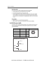
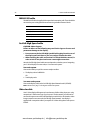
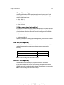
E-Series
Networked Display
Installation Manual
Document Number: 87043_1
Date: December 2004
www.busse-yachtshop.de | [email protected]
Trademarks and registered trademarks
Autohelm, HSB, Raymarine, RayTech, RayTech Navigator, Sail Pilot,
SeaTalk and Sportpilot are registered trademarks of Raymarine
Limited. Apelco is a registered trademark of Raymarine Holdings
Limited (Registered in all major marketing territories).
AST, Autoadapt, Auto GST, Autoseastate, Autotrim, Bidata, Marine
Intelligence, Maxiview, On Board, Raychart, Raynav, Raypilot, Raystar,
ST40, ST60, Seaclutter, Smart Route, Tridata and Waypoint Navigation
are trademarks of Raymarine Limited.
Navionics is a registered trademark of Navionics Company, Italy. All
other product names are trademarks or registered trademarks of their
respective owners.
Copyright: ©Raymarine 2004
www.busse-yachtshop.de | [email protected]
Table of Contents
Chapter 1:
Preparation for installation ..................................................................1
1.1 General information ............................................................................................. 1
Intended use ................................................................................................... 1
Contents of this pack ....................................................................................... 2
Pack details ...............................................................................................2
Dimensions ..................................................................................................... 3
E80 Display .......................................................................................... 3
E120 Display ........................................................................................ 3
Accessories and spares ................................................................................... 4
Accessories ................................................................................................4
Spares ....................................................................................................... 4
1.2 Planning the installation ....................................................................................... 5
EMC Installation Guidelines ............................................................................ 5
Suppression Ferrites .............................................................................6
Connections to other equipment ......................................................... 6
Where should the Display unit be located? ..................................................... 6
EMC Conformance .......................................................................................... 6
Chapter 2:
System Integration .................................................................................7
2.1 What is System Integration? ................................................................................. 7
What is SeaTalk? ............................................................................................. 7
SeaTalk ...................................................................................................... 7
SeaTalk2 .................................................................................................... 7
What is SeaTalk High Speed? ..................................................................... 8
What is NMEA? ...............................................................................................8
NMEA 0183 ...............................................................................................8
NMEA 2000 ...............................................................................................8
2.2 Compatibility ........................................................................................................ 9
Radar Scanners ...............................................................................................9
Digital Sounder Module .................................................................................. 9
Media storage cards ......................................................................................10
Navionics Chart cards ..............................................................................10
CompactFlash cards ................................................................................10
2.3 Functionality .......................................................................................................10
2.4 How is an E-Series integrated? ...........................................................................11
Single display system ....................................................................................12
Networking E-Series Displays ........................................................................13
A typical two node system incorporating two displays ..................................14
An example of a three (or more) node system ...............................................15
www.busse-yachtshop.de | [email protected]
Table of Contents
Chapter 3:
Installation .............................................................................................17
3.1 How can the display unit be mounted? ...............................................................17
Mounting the Display on the trunnion bracket ..............................................17
Flush mounting the Display ...........................................................................19
How is the front cover clip-on attached to the display? .................................20
How do I remove the front cover clip-on? ......................................................21
3.2 Cables .................................................................................................................22
Siting and securing cables .............................................................................22
What cables do I need to connect? ................................................................22
How are the cables connected to the display? ...............................................23
How do I use the cable splicers? ..............................................................24
Power cable .............................................................................................24
Extension cable ..................................................................................25
Fuse ratings .......................................................................................25
SeaTalk/Alarm out cable ................................................................................25
NMEA 0183 cable .........................................................................................26
SeaTalk High Speed cable ..............................................................................26
Two node system ...............................................................................26
3 or more node system .......................................................................26
Video In cable ................................................................................................26
Composite source type ............................................................................27
S-Video source type (not supplied) ..........................................................27
VGA Out (not supplied) .................................................................................27
SeaTalk2 (not supplied) .................................................................................27
Radar cable (not supplied) ............................................................................28
Connecting to a Radome .........................................................................28
Connecting to an open array ...................................................................28
...for new installations .......................................................................28
... to replace a Raymarine Pathfinder Display .....................................29
Chapter 4:
Commissioning the system .................................................................31
4.1 Introduction ........................................................................................................31
4.2 What input does my E-Series require? ................................................................31
4.3 Pre-start checks ..................................................................................................32
Radar .................................................................................................32
Fishfinder ...........................................................................................32
GPS ....................................................................................................32
4.4 Initial power on procedure ..................................................................................33
4.5 How do I test and align the radar? ......................................................................33
Radar transmission check .............................................................................34
www.busse-yachtshop.de | [email protected]
Table of Contents
Radar alignment checks ................................................................................34
Bearing alignment ...................................................................................35
... with your boat moored ...................................................................35
... with your boat under way ..............................................................35
How do I adjust the bearing alignment? ............................................35
4.6 How do I check the GPS? ....................................................................................36
4.7 How do I check the heading data? ......................................................................37
4.8 How do I check the Chart application? ...............................................................37
4.9 How do I test the Fishfinder application? ............................................................38
4.10 How do I test the video? .....................................................................................39
4.11 How do I test the SeaTalkHS Switch connection? ................................................39
4.12 How do I test instrument data? ...........................................................................39
From SeaTalk or SeaTalk2 ...................................................................39
From third party devices on NMEA 0183 ............................................39
Chapter 5:
Troubleshooting ....................................................................................41
5.1 How can I troubleshoot my Display? ...................................................................41
5.2 How can I get Technical Support? .......................................................................42
World wide web ............................................................................................42
Help us to help you ........................................................................................42
How can I contact Raymarine in the US? .......................................................43
Who do I contact for accessories and parts? ............................................43
Who do I contact for product repair and service? .....................................43
How can I contact Raymarine in Europe? ......................................................44
www.busse-yachtshop.de | [email protected]
Table of Contents
www.busse-yachtshop.de | [email protected]
Important Information
i
Important Information
Safety notices
WARNING:Navigation aid
This product is intended to be used as an aid to navigation. Its
accuracy can be affected by many factors, including
equipment failure or defect, environmental conditions and
incorrect handling or use. It is the Users responsibility to
exercise common prudence and navigational judgement. This
device should not be relied upon as a substitute for such
prudence and judgement.
WARNING:Product installation
This equipment must be installed in accordance with the
instructions in this handbook. Failure to do so could result in
poor product performance, personal injury and/or damage to
the vessel.
WARNING:Electrical safety
Make sure the power supply is switched off before making
any electrical connections.
WARNING:Electromagnetic energy
The radar scanner transmits electromagnetic energy. Ensure
that the scanner has been installed according to the
recommendations given in the relevant scanner handbook.
WARNING:Fishfinder sounder module
Removing the transducer cable from the fishfinder sounder
module whilst it is switched on can cause sparks and may
damage the unit. Only remove the transducer cable after
power has been switched off. Ensure that the sounder module
is mounted where it is well ventilated and in an area free from
flammable vapors.
www.busse-yachtshop.de | [email protected]
ii
E-Series Installation Manual
CAUTION: Radar Scanners, Cables & Installation
Information on radar scanners, cables and their installation contained in
this handbook supersedes that contained in the Pathfinder Radar
Scanner Handbook, Document No. 81154_6, dated 11th March 2002.
CAUTION: Front cover clip-on installation
After installing the front cover clip-on, check that all buttons and soft
keys have passed through completely and are free to operate correctly.
CAUTION: Global Positioning System Antenna
Do not connect or disconnect the GPS antenna from the display unit
whilst power is switched on. Doing this may result in irreparable damage
CAUTION: Water Ingress
To prevent the ingress of water and damage to the display:
• Ensure that the chart card door is firmly closed. This can be confirmed
by an audible click.
• Do not remove the SeaTalk High Speed blanking plug from the rear of
the display until such time as you are ready to connect the cable.
• Ensure that the SeaTalk High Speed cable is clicked into place AND
then turned to lock it.
CAUTION: Connections into display
Ensure power is switched off prior to connecting or removing any cables
into the rear of the display. Failure to do so can cause irreparable
damage.
CAUTION: CompactFlash Card Installation
When installing CompactFlash cards ensure that the card is being fitted
the correct way round. DO NOT try and force the card into position as this
may result in irreparable damage to the card.
CAUTION: CompactFlash Cards
Removing the CompactFlash card whilst information is being written to
it may cause damage to the card and loss of all data. A warning on the
display indicates when writing is in progress.
CAUTION: Chart and CompactFlash card damage
DO NOT use a metallic instrument such as a screwdriver or pliers to help
you remove a card, as doing this can cause irreparable damage to the
card and/or display unit.
www.busse-yachtshop.de | [email protected]
Important Information
iii
EMC Conformance
All Raymarine equipment and accessories are designed to the best industry standards
for use in the recreational marine environment.
The design and manufacture of Raymarine equipment and accessories conform to the
appropriate Electromagnetic Compatibility (EMC) standards, but correct installation is
required to ensure that performance is not compromised.
Handbook information
To the best of our knowledge, the information in this handbook was correct when it
went to press. However, Raymarine cannot accept liability for an inaccuracies or
omissions it may contain.
In addition, our policy of continuous product improvement may change specifications
without notice. Therefore Raymarine cannot accept liability for any differences
between the product and the handbook.
www.busse-yachtshop.de | [email protected]
iv
E-Series Installation Manual
www.busse-yachtshop.de | [email protected]
Chapter 1: Preparation for installation
1
Chapter 1: Preparation for installation
1.1 General information
Intended use
This handbook provides information and instructions to assist in planning and
installing your Raymarine E-Series Networked Display, together with information that
will be useful when you are connecting the E-Series Display to other equipment.
In order to obtain the best results in operation and performance, please read this
handbook thoroughly.
www.busse-yachtshop.de | [email protected]
2
E-Series Installation Manual
Contents of this pack
The E- Series (E80 or E120) Networked Display pack contains the following items:
Pack details
Part name
Part no.
E80
E120
Networked display
E02011
E02013
Front cover clip-on
R58183
R58194
Sun cover
R58184
R58195
Cables (all 1.5m):
• Power
• NMEA
• SeaTalk/Alarm out
• SeaTalk High Speed Network
• Video-in cable
R89005
E55053
E55054
E55049
E55057
Cable splice (x3)
07453
For trunnion mounting the display:
• Trunnion bracket
R58204
R58205
3034-009
3034-009
• Washer M6 penny (x5)
23055
23055
• Nut M6 Nylok (x5)
22030
22030
For flush mounting the display:
• Panel seal
R58182
R58193
• Bolts - M4 x 40 hexhead (x4)
15510
155510
• Nuts - M4 (x4)
22024
22024
• Washers - M4 (x4)
23070
23070
• Spring washers - M4 (x4)
23040
23040
• Trunnion bracket knobs (x2)
• Bolt M6 x 50 (x5)
Document wallet containing:
• Reference Manual
• Installation Manual
• Operating Guide
• Flush mount template
Cleaning cloth
84176_1
4472-001-f
Note: To prevent damage, unpack the display carefully. Save the carton and packing, in case
the unit has to be returned for service.
www.busse-yachtshop.de | [email protected]
Chapter 1: Preparation for installation
3
Dimensions
The dimensions for your E-Series display are:
E80 Display
Weight 4.18 kg
PAGE
ACTIVE
WPTS
MOB
MENU
OUT
RANGE
IN
OK
252 mm (9.92 in)
212 mm (8.35 in)
DATA
CANCEL
9.5 mm (0.375 in)
283 mm (11.14 in)
123 mm (4.84 in)
315 mm (12.4 in)
154 mm (6.1 in)
182 mm (7.2 in) clearance
D7206-1
E120 Display
Weight 7.35 kg
PAGE
MENU
OUT
RANGE
IN
OK
264 mm (10.4 in)
WPTS
MOB
DATA
291 mm (11.45 in)
ACTIVE
CANCEL
9.5 mm (0.4 in)
129 mm (5.08 in)
356 mm (14 in)
388 mm (15.3 in)
154 mm (6.1 in)
182 mm (7.2 in) clearance
D7207-1
www.busse-yachtshop.de | [email protected]
4
E-Series Installation Manual
Accessories and spares
Raymarine accessories and parts can be obtained from your authorized Raymarine
dealer. However, if you are in need of an item not available from the retailer or you are
uncertain what item to choose for your Display, please contact Raymarine direct - See
“How can I get Technical Support?” on page 42.
Accessories
The following accessories can be purchased to enhance your E-Series display:
Accessory item
Part no.
Cables:
• SeaTalk High Speed Network (1.5m)
E55049
• SeaTalk High Speed Network (5m)
E55050
• SeaTalk High Speed Network (10m)
E55051
• SeaTalk High Speed Network (20m)
E55052
2
• SeaTalk /NMEA 2000 (1.5m)
E55053
• SeaTalk/Alarm Out (1.5m)
E55054
• VGA Out (10m)
E55055
• VGA Out (20m)
E55056
• Video In - Composite (1.5m)
E55057
• Video In - S-Video (1.5m)
E55062
SeaTalk High Speed Network Switch
E55058
NMEA 0183 Multiplexer
E55059
SeaTalk High Speed Network Crossover Coupler
E55060
M1500 Monitor
E02009
Spares
You can purchase the following spares:
Spares item
Part no.
E80
E120
Flush mount seal
R58182
R58193
Front cover clip-on
R58183
R58194
Sun cover
R58184
R58195
www.busse-yachtshop.de | [email protected]
Chapter 1: Preparation for installation
5
1.2 Planning the installation
This section provides information and advice for planning the installation of your
Display.
EMC Installation Guidelines
All Raymarine equipment and accessories are designed to the best industry standards
for use in the recreational marine environment.
Their design and manufacture conforms to the appropriate Electromagnetic
Compatibility (EMC) standards, but correct installation is required to ensure that
performance is not compromised. Although every effort has been taken to ensure that
they will perform under all conditions, it is important to understand what factors could
affect the operation of the product.
The guidelines given here describe the conditions for optimum EMC performance, but
it is recognized that it may not be possible to meet all of these conditions in all
situations. To ensure the best possible conditions for EMC performance within the
constraints imposed by any location, always ensure the maximum separation possible
between different items of electrical equipment.
For optimum EMC performance, it is recommended that wherever possible:
• Raymarine equipment and cables connected to it are:
• At least 3 ft. (1 m) from any equipment transmitting or cables carrying radio signals e.g. VHF radios, cables and antennas. In the case of SSB radios, the distance
should be increased to 7 ft. (2 m).
• More than 7 ft. (2 m) from the path of a radar beam. A radar beam can normally
be assumed to spread 20 degrees above and below the radiating element.
• The equipment is supplied from a separate battery from that used for engine start.
Voltage drops below 10 V, and starter motor transients, can cause the equipment
to reset. This will not damage the equipment, but may cause the loss of some information and may change the operating mode.
• Raymarine specified cables are used. Cutting and rejoining these cables can compromise EMC performance and must be avoided unless doing so is detailed in the
installation manual.
• If a suppression ferrite is attached to a cable, this ferrite should not be removed. If
the ferrite needs to be removed during installation it must be reassembled in the
same position.
www.busse-yachtshop.de | [email protected]
6
E-Series Installation Manual
Suppression Ferrites
The illustration shows typical cable suppression
ferrites used with Raymarine equipment. Always
use the ferrites supplied by Raymarine.
D6626-1
Connections to other equipment
If your Raymarine equipment is to be connected to other equipment using a cable not
supplied by Raymarine, a suppression ferrite MUST always be attached to the cable
near to the Raymarine unit.
Where should the Display unit be located?
Your E-Series display can either be flush-mounted or mounted using the trunnion
bracket supplied.
Before you install the display, plan its installation, considering:
• Convenience: The contrast and colors seen on all Liquid Crystal Displays (LCD)
vary slightly with viewing angle and are best viewed perpendicular to the display.
The mounting location should be easily accessible to allow operation of the front
panel controls. Avoid installing where excessive reflection will occur in normal use.
• Access: There must be sufficient space behind the display to allow cable connections to the rear panel connectors, avoiding tight bends in the cables.
• Interference: The selected location should be far enough away from devices that
may cause interference, such as motors, generators and radio transmitters/receivers (see EMC Guidelines).
• Magnetic compass: Mount the display at least 3ft (1m) away from a magnetic
compass.
• Cable runs: The display should be mounted as near as possible to a Direct Current
(DC) power source. All cables should be adequately secured, protected from physical damage and excessive vibration. Avoid running cables through bilges or doorways, or close to moving or hot objects.
• Environmental: The display should be protected from physical damage and
excessive vibration. Although the display unit is waterproof, it is good practice to
mount it in a protected area away from prolonged and direct exposure to rain and
salt spray. The rear of the display should be in a well ventilated space to ensure air
circulation to the rear of the unit.
EMC Conformance
Always check the installation before going to sea to make sure that it is not affected by
radio transmissions, engine starting etc.
www.busse-yachtshop.de | [email protected]
Chapter 2: System Integration
7
Chapter 2: System Integration
Introduction
This chapter provides an overview of system integration, you may find that your
system does not use all the protocols or contain all the instrumentation that is
described in it. However it is hoped that the information supplied will help in your
understanding of how systems can be integrated and used successfully.
2.1 What is System Integration?
System integration enables various instruments and displays to communicate with
each other and use the collected data to increase the functionality of the system.
This data exchange is only possible if the data gathering is accurate, and transfer
between instruments is fast and accurate.
Fast and accurate data transfer is achieved by using a combination of the following
data protocols:
• SeaTalk.
• SeaTalk2.
• National Marine Electronics Association (NMEA)0183.
• NMEA 2000.
• SeaTalk High Speed.
When two or more E-Series Displays are networked, all shared data can be viewed on
any display.
What is SeaTalk?
SeaTalk
The SeaTalk protocol enables compatible instruments to be connected to a simple
network by way of a single cable carrying power (12 volts, 150 mA) and data in/out,
without a central processor.
Additional instruments and functions can be added to a SeaTalk system, simply by
plugging them into the network. SeaTalk equipment can also communicate with other
non-SeaTalk equipment via the NMEA 0183 standard, provided a suitable interface is
used.
SeaTalk2
SeaTalk2 is an enhanced replacement for SeaTalk and is a proprietary extension to
NMEA 2000 and the proven CAN bus technology. It enables other Raymarine SeaTalk2
www.busse-yachtshop.de | [email protected]
8
E-Series Installation Manual
devices to talk to each other, whilst maintaining near transparent NMEA 2000
compatibility.
What is SeaTalk High Speed?
SeaTalk High Speed is designed to provide a ‘plug and play’, ethernet based marine
network. It supports up to 8 nodes e.g. 7 displays and a DSM300, which can be
connected to a compatible device, display, DSM etc. to give you access to all radar,
fishfinder, chart cartridge and instrument data, waypoints, routes, tracks and
navigation information held on the system.
What is NMEA?
NMEA 0183
The NMEA 0183 Data Interface Standard was developed by the National Marine
Electronics Association of America. It is an international standard to enable equipment
from many different manufacturers to be connected together and share information.
The NMEA 0183 standard carries similar information to SeaTalk. However it has the
important difference in that one cable will only carry information in one direction. For
this reason NMEA 0183 is generally used to connect a data receiver and a transmitter
together, e.g. a compass sensor transmitting heading to a radar display.
This information is passed in ‘sentences’, each of which has a three-letter sentence
identifier. It is therefore important when checking compatibility between items that
the same sentence identifiers are used:
• VTG - carries Course and Speed Over Ground data.
• GLL - carries latitude and longitude.
• DBT - carries water depth.
• MWV - carries relative wind angle and wind speed data.
NMEA 2000
NMEA 2000 offers significant improvements over NMEA 0183, most notably in speed
and connectivity. Up to 50 units can simultaneously transmit and receive on a singlephysical bus at any one time, with each node being physically addressable.
The standard was specifically intended to allow for a whole network of marine
electronics from any manufacturer to communicate on a common bus via
standardized message types and formats.
www.busse-yachtshop.de | [email protected]
Chapter 2: System Integration
9
2.2 Compatibility
Radar Scanners
CAUTION: Radar Scanners, Cables & Installation
Information on radar scanners, cables and their installation contained in
this handbook supersedes that contained in the Pathfinder Radar
Scanner Handbook, Document No. 81154_6, dated 11th March 2002.
To achieve full radar compatibility with your E-Series Display, your Raymarine radar
scanner may require upgrading. Please check the list below to see if this upgrade is
required.
The scanner serial number can be found on a label attached to the scanner casing:
Scanner type
Serial Number
Compatibility
2Kw Radome
1220000 and below
Not compatible
1220001 - 0530157
Upgrade required
0530158 and above
Fully compatible
1220000 and below
Not compatible
1222001 - 0530246
Upgrade required
0530247 and above
Fully compatible
1030000 and below
Not compatible
1030001 - 1230143
Upgrade required
1230144 and above
Fully compatible
0430000 and below
Not compatible
0430001 and above
Fully compatible
4Kw Radome
4Kw Open Array
10Kw Open Array
The Open Array system will also require a split pedestal cable.
If your radar scanner requires upgrading, please contact your local Raymarine dealer
for full information.
Digital Sounder Module
Important:
In order for your Digital Sounder Module (DSM) to be compatible with your E-Series
display, you will need a DSM300 (Part no. E63049).
www.busse-yachtshop.de | [email protected]
10
E-Series Installation Manual
Media storage cards
Navionics Chart cards
To use your E-Series Display as a navigation aid, charts with detailed information for
the area you wish to navigate are required. The charts are available on Navionics®
Chart cards.
A chart card provides an appropriate level of detail and scale for a given geographic
area.
To obtain suitable Navionics Chart Cards, contact your local dealer or visit the
Navionics web sites: www.navionics.com or www.navionics.it.
Alternatively, in North America call Navionics toll-free on 1-800-848-5896.
Outside of North America, contact your local dealer or call Navionics SpA on tel:
(+39) 0584 961696 or fax: (+39) 0584 961309.
CompactFlash cards
It is possible to archive or transfer information to and from your E-Series display and
other compatible instruments using CompactFlash cards. To achieve the best results it
is recommended that SAN DISK® CompactFlash cards are used.
2.3 Functionality
For full functionality of the displays the following position and heading data is
required:
• Orientation - requires heading data derived from a suitable compass, for the
radar to operate in North Up or Course Up mode and the chart to operate in Course
Up and Head Up modes.
• Man Overboard (MOB) - requires heading and speed data. Alternatively, use
speed over ground (SOG) and course over ground (COG) derived from the same
source as position data (GPS).
• Mini Automatic Radar Plotting Aid (MARPA) and radar/chart overlay functions - requires accurate heading data. MARPA functionality is provided
if SOG and COG are also available. Increased accuracy will be obtained by using
fast heading data from a suitable compass, Smart heading sensor or compatible
Raymarine autopilot.
• Chart display - requires position data (GPS).
www.busse-yachtshop.de | [email protected]
Chapter 2: System Integration
11
2.4 How is an E-Series integrated?
You can integrate:
• A single E-Series display.
OR:
• Connect two E-Series displays or an E-Series display and a DSM 300 via a crossover
coupler.
OR:
• Connect two or more E-Series displays and a DSM300 if required via a SeaTalk High
Speed switch to form a network.
The diagrams that follow show three suggested set ups. These are not however the
only possible combinations:
www.busse-yachtshop.de | [email protected]
12
E-Series Installation Manual
Single display system
This simple system incorporates a single E-Series display with a DSM 300 and radar.
E-series display
SeaTalk high speed
Open array scanner
Radome scanner
or
Crossover
coupler
DSM 300
Video IN
SeaTalk/Alarm out
Radar
Power
NMEA
Power
To:
Video player
Onboard camera
DVD player
To:
SeaTalk system
Remote audible alarm
RF ground/earth
PC via interface box
Transducer
Key
Supplied
Not supplied/
accessory
Power Cables
Red
12V or 24V DC
Black
0V
Ground/Earth RF Ground
Third party equipment
NMEA multiplexer
Fast heading sensor
RS232 interface
Autopilot
D7204-1
www.busse-yachtshop.de | [email protected]
Chapter 2: System Integration
13
Networking E-Series Displays
You can connect two or more E-Series Displays to create a network. This will enable
you to input, view and maintain data across all your Displays and enable multiple
SeaTalk instruments to communicate with one another.
When you are installing a network of E-Series Displays you should note the following:
• One display will act as the master, into which all SeaTalk/SeaTalk2 connections
should be made.
• If you connect the master display to all other displays in the system via SeaTalk or
SeaTalk2, you will negate the need to unplug and reconnect cabling if the master
becomes redundant.
• The bridging of data from SeaTalk/SeaTalk2 only occurs at the master. You cannot
therefore have additional networks connected to additional E-Series Displays. You
can however connect multiple NMEA inputs.
• As it is not possible to view a video image across the network, you should connect
the Video In cable to the display on which you wish to view the image.
The following two pages detail a simple E-Series Networked System with two E-Series
displays and no DSM and a more advanced, multiple node system incorporating two
(or more) displays and a DSM 300.
www.busse-yachtshop.de | [email protected]
14
E-Series Installation Manual
A typical two node system incorporating two displays
Key
Open array scanner
Supplied
Not supplied/
accessory
Radome scanner
or
SeaTalk high speed
SeaTalk high speed
E-series display
E-series display
Video In
Video In
Crossover
coupler
To:
Video player
Onboard camera
DVD player
Power
SeaTalk2/NMEA
Third party equipment
NMEA multiplexer
Fast heading sensor
RS232 interface
Autopilot
Power
To:
Video player
Onboard camera
DVD player
SeaTalk/Alarm out
To:
SeaTalk system
Remote audible alarm
RF ground/earth
PC via interface box
Power Cables
Red
12V or 24V DC
Black
0V
Ground/Earth RF Ground
D7346-1
www.busse-yachtshop.de | [email protected]
To:
Fast heading sensor
NMEA GPS
DSC radio
Power
E-series display
(master display)
Raymarine equipment
Radar
or
www.busse-yachtshop.de | [email protected]
To:
3rd party
equipment
To:
SeaTalk system
Remote alarm
RF ground/earth
PC via interface box
Additional E-Series
displays
To:
Video player
Onboard camera
DVD player
Video in
Power
To:
VGA/SVGA monitor
Plasma screen
M1500 monitor
DSM 300
D7205-1
Power
Power Cables
Red
12V or 24V DC
Black
0V
Ground/Earch RF Ground
SeaTalk high speed
Not supplied/
accessory
Supplied
VGA out
Key
To:
Video player
Onboard camera
DVD player
Video in
Additional E-series display
Additional
displays
SeaTalkHS switch
Additional NMEA
connections
SeaTalk
high speed
To:
2
SeaTalk system
Additional E-Series
displays
SeaTalk2
Power
SeaTalk high speed
Radome scanner
SeaTalk/alarm out
To:
NMEA
multiplexer
NMEA 0183
Open array scanner
Chapter 2: System Integration
15
An example of a three (or more) node system
16
E-Series Installation Manual
www.busse-yachtshop.de | [email protected]
Chapter 3: Installation
17
Chapter 3: Installation
CAUTION:
Please ensure that you have read Chapter 1: Preparation for installation
before proceeding.
CAUTION: Radar Scanners, Cables & Installation
Information on radar scanners, cables and their installation contained in
this handbook supersedes that contained in the Pathfinder Radar
Scanner Handbook, Document No. 81154_6, dated 11th March 2002.
Introduction
This chapter provides instructions for installing your E-Series Display. You may find that
your system does not use all the protocols or contain all of the instrumentation that is
described.
3.1 How can the display unit be mounted?
CAUTION: Installation
Make sure there are no hidden electrical wires or other items
behind the selected location before proceeding.
Make sure there is sufficient rear access for mounting AND
cabling.
The display unit is waterproof to CFR 46 and can be installed either above or below
deck using either the trunnion bracket or by flush mounting it in a suitable position.
Mounting the Display on the trunnion bracket
The display unit can be fitted on a dash, chart table, bulkhead or deckhead, using the
trunnion bracket:
You should fit the trunnion bracket as follows:
1. Mark the location of the trunnion bracket screw holes on the chosen mounting surface.
2. Drill pilot holes for the screws using a suitable drill, taking care that there are no
cables or anything that may be damaged behind the surface.
3. Use the 5 bolts supplied (together with the washers and nuts) to securely attach the
bracket.
4. Before attaching the display unit to the bracket:
www.busse-yachtshop.de | [email protected]
18
E-Series Installation Manual
i. Locate the front cover clip-on over the front of the display - see page 20.
ii. Check that the buttons have passed through the cover and are free to operate.
It is suggested that you use your thumb or forefinger in a circular motion to do
this.
5. Attach the display unit into the trunnion bracket, adjusting the unit to the required
angle for clear vision.
6. Tighten the trunnion knobs.
Trunnion mounted display
E-series display unit
Front cover clip-on
Trunnion knob (x 2)
Trunnion bracket
Bolt - M6 x 50mm
(x 5)
Washer
(x5)
Button
washer (x5)
Nyloc (x5)
www.busse-yachtshop.de | [email protected]
D7211_1
Chapter 3: Installation
19
Flush mounting the Display
You should flush mount your display as follows:.
1. Check the selected location for the unit. A clear, flat area with suitable clearance
behind the unit, is required.
2. Fix the appropriate template - E80 or E120, supplied in the document wallet, to the
selected location, using self-adhesive tape.
3. Using a suitable hole saw, the size is indicated on the template, make a pilot hole
in each corner of the cut-out area.
4. Using a suitable saw, cut along the inside edge of the cut-out line.
5. Ensure that the unit fits into the area that has been cut out and then file around the
cut edge until smooth.
6. Drill four 4.5 mm holes as indicated on the template, to accept the securing bolts.
7. Remove the backing tape from the panel seal and place the seal onto the display
unit and press firmly onto the flange.
8. Connect all the cables that are in use to the rear of the display, avoiding tight bends.
9. Slide the unit into the console and secure using the bolts supplied.
10. Fit the front cover clip-on onto the display - see page 20.
Washer,
M4 (x4)
Flush mounted display
Spring
washer,
M4 (x4)
Bolt, M4 x 40 hexhead (x4)
Nut,
M4 (x4)
Front cover clip-on
E-series display unit
Panel seal
D7212_1
www.busse-yachtshop.de | [email protected]
20
E-Series Installation Manual
How is the front cover clip-on attached to the display?
The front cover clip-on is attached as follows:
D7213_1
1. Carefully lift one edge of the screen protection film, so that it is accessible for
removing when unit installation is complete.
2. Place the front cover clip-on onto the E-Series Display, ensuring that the locking
lugs (located at the bottom edge of the covers) are latched into position.
3. Ensure that the control buttons pass through their respective openings.
4. Apply firm but even pressure to the cover along the:
i. outer edges - work from the sides upwards and then along the top edge, to
ensure that it clips securely into position.
ii. inner edges - particularly along the chart card door edge, to ensure that the clipon sits flat.
5. Check that all control buttons are free to operate.
www.busse-yachtshop.de | [email protected]
Chapter 3: Installation
21
How do I remove the front cover clip-on?
D7214_1
To remove the clip- on front cover:
1. To prevent damaging your dash or placing undue strain on the trunnion bracket,
remove the unit from its mounting before proceeding. If you have flush mounted
your Display and cannot readily gain access to the rear of the unit, protect the dash
and proceed with caution.
2. Using a flat-bladed screwdriver placed in the aperture at the top right of the front
cover clip-on, gently twist it to release the top clips.
3. Working from this corner, free the clips along the top edge of the display by hand,
then work towards the bottom edge. Taking care to ensure that the control buttons
pass through the clip-on. DO NOT lever along the top edge.
4. Carefully free the locating clips at the bottom of the clip-on by lowering it away
from the unit - DO NOT USE A SCREWDRIVER FOR THIS AS IT WILL DAMAGE THE
CLIPS.
5. Remove the clip-on front cover from the display.
www.busse-yachtshop.de | [email protected]
22
E-Series Installation Manual
3.2 Cables
This section details how to instal and connect all the relevant cables to your E-Series
Display.
Siting and securing cables
When installing system cables, please note the following:
• All cables should be adequately secured, protected from physical damage and
exposure to heat. Avoid running cables through bilges or doorways, or close to
moving or hot objects.
• Acute bends must be avoided.
• Where a cable passes through an exposed bulkhead or deckhead, a watertight
feed-through should be used.
• Secure cables in place using tie-wraps or lacing twine. Coil any extra cable and tie
it out of the way.
• Do not pull cables through a bulkhead or deckhead using a cord
attached to the connector as this could damage the connections.
• Do not remove the SeaTalk High Speed blanking plug from the rear of the
display until such time as you are ready to connect the cable. Failure to adhere to
this, may result in the ingress of water and permanent damage to the display.
What cables do I need to connect?
To ensure that your E-Series Display functions correctly, you will need to connect the
following cables:
• Power cable.
• SeaTalk/Alarm Out cable (if SeaTalk system connected).
• NMEA cable (if third party equipment, NMEA multiplexer, fast heading sensor,
RS232 interface or course computer fitted).
• SeaTalk2 cable (if Sea Talk2 system connected).
• SeaTalk High Speed cable (if a DSM or second display is fitted).
• Video In cable (if a video player, on-board camera or DVD player fitted).
• Radar cable (not supplied).
• VGA Out cable (if an M1500 monitor or additional screen is fitted).
www.busse-yachtshop.de | [email protected]
Chapter 3: Installation
23
How are the cables connected to the display?
The cable connections are located on the back of the display unit. All cables can be
connected prior to mounting the unit on the trunnion bracket.
CAUTION: Do not remove the SeaTalk High Speed blanking plug from
the rear of the display until such time as you are ready to connect the
cable. Failure to adhere to this may result in the ingress of water and
permanent damage to the display.
Cable connections
SeaTalkHS
VGA out
Supplied
Not supplied/accessory
Power
NMEA SeaTalk/ SeaTalk2
Alarm out
Video in
D7210-1
Radar
Note: For details of what is connected to each of these cables please refer to the diagrams on
page 12, page 14 and page 15.
www.busse-yachtshop.de | [email protected]
24
E-Series Installation Manual
How do I use the cable splicers?
The cable splicers are used to make the connections between the cables easy and
secure, without removing insulation from cable tails.
To use these connectors:
cable splicer
D6615_1
1. Place the wires to be joined into the connectors, ensuring correct polarity and that
the wires are pushed fully home.
2. Using a pair of pliers, crimp the connector bulb together.
3. Check that a secure connection has been made.
4. Ensure that the cables are secured in a suitable position to prevent the join being
placed under strain.
Power cable
The E-Series Display is intended for use on boats’ DC power systems
rated at 12v or 24v.
The power connection should be made at either the output of the
battery isolating switch, or at a DC power distribution panel. Raymarine
recommends that power is fed directly to the display and scanner via its
own dedicated cable system and MUST be protected by a thermal circuit
breaker or fuse, installed close to the power connection.
This cable is supplied ready for connecting to your boats DC power supply, with a
length of screen exposed before the positive and negative wire tails.This screen should
be clamped to your boat’s earth/ground with a saddle clamp, as shown below:
Step 1
Slide towards tails
Pre-cut line
Step 2
Attach to ship's ground
D6621-2
www.busse-yachtshop.de | [email protected]
Chapter 3: Installation
25
Extension cable
If an extension power cable is required, please note the following:
• The wire gauge used may be affected by the scanner type.
• To minimize voltage drops, use large gauge cable.
• Use the supplied power cable to connect to the display unit. Then use a suitable
connector block to connect the free end to the extension cable, taking particular
care to ensure the correct polarity. The supplied power cable has a cross section of
10 mm.
Fuse ratings
• Without a scanner - use a 6.3 amp anti-surge fuse.
• With a scanner - refer to the fuse notification in the scanner handbook.
SeaTalk/Alarm out cable
The SeaTalk cable is supplied with insulated tails. These should be connected to your
existing equipment using either the cable splicers supplied or by using a standard
screw terminal block.
Function
Color
Pin no.
SeaTalk power
Red
1
SeaTalk return
Black
2
SeaTalk data
Yellow
3
Alarm out (open collector) White
4
Alarm return
Brown
5
Screen (RFground/earth)
Unsheathed/Drain wire
6
Rear unit view
1
5
2
3
Connections for external alarm
Battery +
Alarm
(100mA max)
Alarm
out
D7482-1
Alarm
return
Battery -
6
www.busse-yachtshop.de | [email protected]
4
D7528-1
26
E-Series Installation Manual
NMEA 0183 cable
The NMEA 0183 cable is supplied with exposed wire connecting tails. These should be
connected to your existing NMEA instruments using suitable connector blocks:
Function
Color
Pin no.
NMEA Input (-ve) common
Green
1
NMEA Input (+ve)
White
2
NMEA Output (+ve)
Yellow
3
NMEA Output (-ve) common Brown
4
Not connected
5
Screen
SeaTalk High Speed cable
CAUTION: Water ingress
Failure to adhere to the following may result in the ingress of water and
permanent damage to the display:
• Do not remove the SeaTalk High Speed blanking plug from the rear of
the display until such time as you are ready to connect the cable.
• When inserting the cable, ensure that it is clicked AND then turned, in
order to lock it into place and create a watertight connection.
How the SeaTalk High Speed cable connects depends on whether you are integrating
your E-Series Display into a two node, or 3-or-more node system.
Two node system
Connect the cable by way of the crossover coupler to either:
• The display unit and a DSM300.
OR
• Two displays units.
3 or more node system
Connect the display unit(s) to the SeaTalk High Speed Network switch (E55058).
Note: Please refer to page 11 for diagrams of these two systems.
Video In cable
Your E-Series display will support on-board cameras, DVD or video players etc. using
composite or S-Video source type. If you have an E-Series network, you will need to
connect the input source to the individual display on which it is to be viewed as video
images cannot be seen across the SeaTalk High Speed network. Your display is
supplied with a composite cable. If you require an S-Video cable, please order part no.
E55062.
www.busse-yachtshop.de | [email protected]
Chapter 3: Installation
27
Composite source type
Use the supplied cable to connect up to 4 composite source inputs to your E-Series
Display. The color of each connector defines the video number to which it configures
within the Video Setup Menu:
•
•
•
•
Black - Video 1
White - Video 2
Red - Video 3
Green - Video 4
S-Video source type (not supplied)
If you wish to use S-Video source type, you will need to purchase an S-Video cable (Part
no. E55062). You can connect 2 inputs using S-video to each E-Series Display. The color
of each connector defines the video number to which it configures within the Video
Setup Menu:
• Black/White - Video 1/2
• Red/Green - Video 3/4
For further information on setting up your video application, please refer to the Video
chapter of the Reference Manual.
VGA Out (not supplied)
Use this cable to connect to VGA/SVGA monitor, plasma screen television or M1500
monitor. Please ensure that any equipment that you connect conforms to the
following:
Display
Resolution
Refresh rate
E120
800 x 600
56 Hz
E80
640 x 480
60 Hz
Note: Please refer to page 4 for details of this accessory.
SeaTalk2 (not supplied)
Use this cable to connect to third party equipment or SeaTalk2 instruments.
If your system networks two or more E-Series displays, you should ensure that the
SeaTalk 2 connection is made to the display that you have defined as your master unit.
Note: Please refer to page 4 for details of this accessory.
www.busse-yachtshop.de | [email protected]
28
E-Series Installation Manual
Radar cable (not supplied)
Having ensured that the radar scanner you are using is compatible with the E-Series
Display (see “Compatibility” on page 9), the cable should be connected as follows:
Connecting to a Radome
If you are using a radome this can be powered through the display. Just run your cable
and connect it to the radome and the display.
If the existing cable is too short, please order from the following:
Part No.
Cable length
Weight
Radome power output
E55065
15m
Heavy
2Kw or 4 Kw
E55066
25m
Heavy
2Kw or 4 Kw
E55067
10m
Light
2kw
E55068
15m
Light
2kw
Connecting to an open array
If you are using an open array, this cannot be powered through the display. You will
need to purchase a split pedestal cable:
...for new installations
Part No
Description
E55063
15m Split pedestal cable
E55064
25m Split pedestal cable
Split pedestal cable
To Open
Array Scanner
To display
To power
Note: You should ensure that the distance (cable route) from the power supply to the
open array is kept to a minimum.
D7209-1
www.busse-yachtshop.de | [email protected]
Chapter 3: Installation
29
The array and the display should be connected using the split pedestal cable as shown:
Open Array
E-Series Display
PAGE
Split pedestal cable
(15 or 25 metres)
ACTIVE
WPTS
MOB
DATA
MENU
OUT
RANGE
IN
OK
Power to open array
CANCEL
Power to display
Note: The power supply for both the display
and the open array must be of the same
voltage (using a convertor if necessary) and
from a common supply source e.g. the same
battery or power breaker.
D7329-1
Boats DC
Power Supply
... to replace a Raymarine Pathfinder Display
Part No
Description
E55069
2.5m Pedestal adaptor cable
Pedestal adaptor cable
To display
To power
To open array
connector
D7327-1
The array and the display should be connected using the pedestal adaptor cable as
shown:
www.busse-yachtshop.de | [email protected]
30
E-Series Installation Manual
Open Array
E-Series Display
PAGE
ACTIVE
WPTS
MOB
DATA
MENU
Pedestal adaptor cable
(2.5 metres)
OUT
RANGE
IN
OK
Power to open array
Boats DC
Power Supply
CANCEL
Power to display
Note: The power supply for both the display
and the open array must be of the same
voltage (using a convertor if necessary) and
from a common supply source e.g. the same
battery or power breaker.
D7328-1
www.busse-yachtshop.de | [email protected]
Chapter 4: Commissioning the system
31
Chapter 4: Commissioning the system
4.1 Introduction
This chapter details the commissioning of your E-Series Display and includes the
following:
• Required input.
• Pre-start checks.
• Initial power on procedure
• Radar checks and alignment.
• Chart application checks.
• Fishfinder checks.
• SeaTalk High Speed checks.
• Video in/out.
4.2 What input does my E-Series require?
The table below details the data required by each application of your E-Series:
Data
GPS
*
Datum
*
Compass, autopilot or
smart heading sensor
*
Scanner
*
DSM 300 only
*
*
*
Video
*
Engine monitor
Digital
Instruments
*
CDI
Multi-media card
Fishfinder
Chart
Radar
Application
*
*
Instruments
*
*
Video input
*
Notes: (1) For full details of scanner compatibility see page 9. If you are still unsure as to
your scanner’s suitability, please refer to an authorized Raymarine dealer.
(2) Engine output from a compatible engine manufacturer is also required. See
Raymarine.com for latest compatibility information.
www.busse-yachtshop.de | [email protected]
32
E-Series Installation Manual
4.3 Pre-start checks
Before you perform any functional tests, please carry out the following pre-start
checks:
Radar
• Check that the scanner has been installed in accordance with the instructions contained in the relevant handbook. All securing bolts should be fully tightened and
any mechanical locking arrangements, as specified, are in place.
• Ensure scanner and power connections have been made.
• If an open array is fitted, ensure that power is connected through a split cable to a
suitable circuit breaker and that the power switch located on the pedestal to set to
ON.
• All connecting wires are secured and protected as necessary.
Note: If you are the boat’s owner and have installed the radar system, ask an authorized Raymarine dealer to check the installation before going to sea.
WARNING:Electromagnetic energy
The radar scanner transmits electromagnetic energy. Ensure
that the scanner has been installed according to the
recommendations in the relevant scanner handbook. Ensure all
personnel are clear of the scanner, before switching to
transmit mode.
Fishfinder
Ensure that the transducer cable is inserted and the bayonet connector locked onto the
DSM 300.
GPS
Check that the GPS has a clear view of the sky and is not obstructed e.g. by buildings,
bridges or other equipment fitted on-board.
www.busse-yachtshop.de | [email protected]
Chapter 4: Commissioning the system
33
4.4 Initial power on procedure
Once you have conducted the pre-start checks you are ready to start the display:
D6577-1
1. Press the POWER button until the introductory logo is displayed:
• The keys light up and after a few seconds a navigation warning is displayed.
• If you have networked two or more E-Series displays, you will also hear an
alarm and be asked to select the repeater displays. Press SET AS REPEATER on
the appropriate Display(s).
• At this time the radar scanner (if fitted and powered) is checked for compatibility with the display. An error message is displayed if the scanner is incompatible.
D6655-3
2. Read the warning and then press OK to remove it. The Select Page Set screen is displayed:
3. Use the trackpad to select the required page set and then press OK.
You are now ready to test that your system is receiving the necessary data to run all the
required applications.
4.5 How do I test and align the radar?
Your E-Series display is part of an integrated system. Raymarine strongly advise that
you test and align the radar before connecting to other systems.
To test and align the radar you must first select a radar application. With the Select
Page Set screen displayed (see previous section):
www.busse-yachtshop.de | [email protected]
34
E-Series Installation Manual
1. Press OK to select the highlighted page set.
2. Press PAGE. The currently selected page set is represented on the soft keys.
3. Press the corresponding soft key to display a full window radar application.
4. The scanner warm-up countdown commences. This will take approximately 70 seconds.
Note: If your scanner is incompatible, a message is displayed. If this is the case, you will be
unable to proceed further with testing and aligning the radar. Refer to Important Information - Radar Scanners at the front of this handbook.
Radar transmission check
With a radar application active, check the transmission to the scanner as follows:
1. Press the RANGE button and ensure that the radar range adjusts accordingly.
2. Check that all the following information is displayed:
• In the status bar - the range, orientation, motion mode and range ring spacing
• In the data bar - a turning radar status icon and vessel position data.
Range
Orientation
Range ring Radar status
icon
spacing
Motion mode
Data bar
Status bar
3nm
Head-Up
Relative Motion
Rings ½nm
Ship's
heading
marker
Boat's
position
VRM/EBL…
TARGET
TRACKING…
GAIN…
TARGETS
DISPLAY…
PRESENTATION…
D6803-2
Range
ring
Radar alignment checks
You should check the bearing and display timing alignment to ensure that an accurate
picture is shown.
www.busse-yachtshop.de | [email protected]
Chapter 4: Commissioning the system
35
Bearing alignment
Adjusting the bearing alignment ensures that targets appear at the correct bearing
relative to your boat’s bow. You need to select a visible target of known bearing that is
displayed on the radar, and then adjust the radar set up as necessary until the correct
bearing reading is obtained.
You can carry out a bearing alignment in two ways:
... with your boat moored
To use this method you will need a hand bearing compass:
1. Visually identify a suitable target, such as a buoy that can be seen towards the edge
of the radar screen. Typically, this will be on the 1.5nm range.
2. Determine the accurate bearing of the target relative to your boat’s bow using the
hand bearing compass. To do this subtract your boat head bearing from the target
visual bearing, these examples may help:
Example 1
Example 2
Visual bearing (a) = 065° M
Visual bearing (a) = 030° M
Ships head bearing (b) = 021° M
Ships head bearing (b) = 042° M
Relative bearing:
= (a) - (b)
Relative bearing:
= (a) - (b)
= 065 - 021 = 044° R
= 030 - 042 = -012
If answer is negative, add 360° =
012 + 360 = 348° R
3. From the primary radar soft keys, press VRM/EBL.
4. Toggle the VRM/EBL soft key to ON. Adjust the EBL to your chosen target. If there is
a difference between your calculated bearing and that shown for the EBL, there is
an alignment error and you will need to carry out bearing alignment adjustment,
See “How do I adjust the bearing alignment?” on page 35.
... with your boat under way
1. Align your boat’s bow with the selected target.
2. Note the position of the target relative to the Ships Heading Marker (SHM) on the
radar picture. If the target is not under the SHM, there is an alignment error and you
will need to carry out bearing alignment adjustment. For details see below.
How do I adjust the bearing alignment?
1. If moored, move the EBL to calculate bearing.
2. With a radar application in the active window, press MENU. The Set Up menu is displayed.
www.busse-yachtshop.de | [email protected]
36
E-Series Installation Manual
3. With RADAR SET UP highlighted, use the trackpad (right) to display the RADAR SET
UP menu.
4. Use the trackpad (up/down) to highlight and then the trackpad (right) to select
BEARING ALIGNMENT. The menu is removed from the screen and the Bearing
Alignment soft key is displayed.
5. Press the BEARING ALIGNMENT softkey.
6. Proceed as follows:
• If the boat is moored - use the rotary control to place the selected target
under the EBL.
• If the boat is under way - use the rotary control to place the selected target
under the SHM.
7. Press OK. The picture updates as the bearing alignment is adjusted.
8. To exit the menu, press OK or CANCEL.
4.6 How do I check the GPS?
The GPS is used to position your boat on the chart. You can set up your Global
Positioning System (GPS) and check its status using the GPS status icons and the GPS
Status page of the Setup menu.
To access the GPS Status page:
1. Press MENU. The Setup menu is displayed.
2. Highlight and then select GPS Status. The GPS Status dialog box is displayed e.g.
0
0
0
0
0
0
0
0
00001.0
SD-FIX
0
0
0
122
0
HDOP
FIX STATUS
SATELLITE DIFFERENTIAL
WGS 1984
DIFF GPS
ON
OFF
DIFF SET UP
OTHER SET UP
RESTART GPS
D6809_2
www.busse-yachtshop.de | [email protected]
Chapter 4: Commissioning the system
37
This screen provides, for each tracked satellite, the satellite number, a graphical signal
strength bar, status, azimuth angle and its elevation angle from your vessel. The sky
view graphic shows the position of these satellites.
Positional accuracy is dependent upon these parameters; in particular, the azimuth
and elevation angles are used in a triangulation process to calculate your position.
Horizontal Dilution of Position (HDOP) is a measure of this accuracy; a higher figure
signifies a greater positional error. In ideal circumstances, the figure should be in the
region of 1.0.
D7453_1
When a connection has been successfully made, the GPS status icon in
the top right-hand corner of the screen reads FIX.
If NO FIX is displayed, please refer to the Troubleshooting section on
page 41.
The option to select differential or satellite differential fix is dependent
upon the capabilities of the attached GPS. If your boat is equipped with a Raymarine
GPS, the Differential GPS can be switched on or off using the appropriate soft key.
4.7 How do I check the heading data?
If your display is connected to a compass, autopilot or fast heading sensor, your boat’s
heading will be displayed in the data bar. If heading data is not available your display
can use COG data. This will however affect the operation of the following functions:
• overlay a radar image over your chart.
• orientate a radar image north-up.
• MARPA.
To linearize (‘swing’) your compass proceed as follows:
1. Press MENU.
2. Select the Compass Setup sub-menu.
3. Press LINEARIZE COMPASS and follow the instructions displayed on screen. When
instructed to align heading, press the ALIGN HEADING soft key and then turn the
rotary control one click at a time to fine tune the heading.
4.8 How do I check the Chart application?
For full functionality of chart applications, you need to ensure that position data is
available at the display via SeaTalk, NMEA, SeaTalk2 or SeaTalk High Speed. To use
your chart as a navigation aid you will need a CompactFlash card (see page 10) with
the appropriate level of detail for the geographic area that you wish to navigate.
Proceed as follows:
www.busse-yachtshop.de | [email protected]
38
E-Series Installation Manual
1. Without a chart card installed, press PAGE.
2. Select a full window chart application by pressing the associated key.
3. Zoom out with the RANGE button until the world map is visible.
4. To ensure that the display is responding to position data:
i. Press FIND SHIP.
ii. Check that the cursor is positioned over the boat symbol in the centre of the display.
5. Insert a chart card containing a suitable chart for the area in which you are located.
Once inserted, the chart should redraw with the cartridge chart boundaries displayed.
Note: For details of how to insert a chart card, please refer to Section 2.7, How do I use
CompactFlash cards? in the Reference Manual.
6. Zoom in with the RANGE button to check that chart data is being displayed.
4.9 How do I test the Fishfinder application?
For the fishfinder application to function it must be connected to a DSM 300. The status
of your DSM is indicated by the boat/fish icon in the data bar (top right-hand corner of
the screen):
DSM status icon
DSM status description
D6892-2
Successful connection to a DSM and transmitting.
(animated icon)
D7451-1
DSM connected but not transmitting.
(static icon)
D7452-1
No DSM connected/recognized.
(greyed-out icon)
1. Press PAGE and select a full window fishfinder application.
2. Using the soft keys, check that individual settings change as they are selected.
Note: If your DSM is not being recognized by your display, please refer to the Troubleshooting
section on page 41. Information about the status LED on the DSM300 is available in the
DSM300 User Manual.
www.busse-yachtshop.de | [email protected]
Chapter 4: Commissioning the system
39
4.10 How do I test the video?
To ensure that the video application is operating you should open a video application
on each display that is connected to a video input/output and check the following:
• Video in - check that an image is being displayed for each input.
Note: If you are using S-Video rather than composite input, you will need to change the
settings in the Video Setup Menu. Please refer to the Reference Manual for more details.
• Video out - once you have attached the M1500 or other monitor, check that the
image from the E-Series unit is being displayed.
If ‘No Signal’ is displayed, check the video in and video out cable connections. If the
problem persists, please contact Raymarine Technical Services (seepage 42).
4.11 How do I test the SeaTalkHS Switch connection?
To ensure that your SeaTalkHS Switch is connected, you should check the following:
• The Switch should display a static green light (right) and a flashing green light (left)
for each connecting port. If your switch is only displaying a left flashing light, data
will be transferred but the connection will be at low speed.
• Open a radar, chart and fishfinder application window on all display units and
check that the appropriate data is displayed throughout the network.
If you are not receiving any data, check the cable connections to the rear of the display
and the SeaTalkHS Switch. If the problem persists, please contact Raymarine Technical
Services (seepage 42).
4.12 How do I test instrument data?
To ensure that your system is receiving instrument data, you should check the
following:
From SeaTalk or SeaTalk2
Open the digital instrument application and ensure all relevant data is displayed. If you
are not receiving data, check cable connections.
From third party devices on NMEA 0183
Check that appropriate NMEA sentences are being sent from the third party device and
on the E-Series Display. Open the digital instrument application and ensure all relevant
data is displayed.
www.busse-yachtshop.de | [email protected]
40
E-Series Installation Manual
www.busse-yachtshop.de | [email protected]
Chapter 5: Troubleshooting
41
Chapter 5: Troubleshooting
Introduction
This chapter provides information on troubleshooting your Raymarine E-Series Display
at installation, and how to get assistance from Raymarine.
5.1 How can I troubleshoot my Display?
All Raymarine products are, prior to packing and shipping, subjected to
comprehensive test and quality assurance programs. However, if you cannot
successfully instal your Display unit, this section will help you to identify the most likely
cause and show the corrective action required.
If, after referring to this section, you are still having problems with your Display, contact
your local dealer, national distributor or Raymarine Technical Services Department for
further advice.
Always quote the product serial numbers which are printed on the back of each unit.
Installation problem
Solution
Display does not function
1. Make sure that the power supply cable is sound
and that all connections are tight and free from
corrosion.
2. Check relevant fuses.
3. Check power source is of correct voltage and
sufficient current.
“Scanner not responding” message
Check that the cable connecting the scanner to
the radar display unit is securely connected and
undamaged.
If using split pedestal cable ensure power ON to
scanner.
“Invalid scanner software: Version
xx.x, Version xx.x required”
Incorrect software version installed. Contact your
local Raymarine dealer.
“Open array cannot be powered from
the display”
Scanner not compatible with Display - refer to
Important Information Section of this manual.
“Scanner hardware fault”
Scanner not functioning - refer to the
Maintenance & Troubleshooting chapter of
Reference Manual for more details.
The bearing displayed on the radar picture is not the same as the actual bearing
Perform the bearing alignment procedures
described in Chapter 4- System Tests and Alignment of this manual.
www.busse-yachtshop.de | [email protected]
42
E-Series Installation Manual
5.2 How can I get Technical Support?
Raymarine provides a comprehensive customer support service, on the world wide
web, through our worldwide dealer network and by telephone help line. If you are
unable to resolve a problem, please use any of these facilities to obtain additional help.
World wide web
Please visit the Customer Support area of our website at: www.raymarine.com/
support
For fastest support - 24 hours a day, seven days a week; go to the Frequently Asked
Questions section. Most questions are answered here.
The website will also give you servicing information, e-mail access to the Raymarine
Technical Support Department and details of the locations of Raymarine agents,
worldwide.
If you don’t have access to the world wide web, contact Technical Support where
specialists are available to answer questions about installing, operating and troubleshooting all Raymarine products.
Help us to help you
When requesting service, please quote the following product information:
• Equipment type.
• Model number.
• Serial number.
• Software issue number
To access this information:
1. Press MENU.
2. Highlight and select System Diagnostics.
3. Highlight and select Software Services.
4. Highlight and select Unit Info. The Unit Info : Software Details screen is displayed
giving full details of your particular unit together with its software.
www.busse-yachtshop.de | [email protected]
Chapter 5: Troubleshooting
43
How can I contact Raymarine in the US?
You can contact Raymarine in the US either using the Raymarine world wide web as
detailed above or by calling one of the telephone numbers below.
Who do I contact for accessories and parts?
You can obtain many Raymarine accessories and parts directly from your authorized
Raymarine dealer. However, if your dealer does not have the item you want, contact
Raymarine Technical Services at:
1-800-539-5539 extension 2333, or
(603) - 881 - 5200
You can use these numbers Monday through Friday 0815to 1700 Eastern Standard
Time or Eastern Daylight Savings Time.
If you are not sure which item is appropriate for your unit, you should first contact the
Technical Support Department at:
1-800-539-5539 extension 2444, or
(603)-881 -5200
to verify your requirements.
Who do I contact for product repair and service?
In the unlikely event that your Raymarine unit should develop a problem, contact your
authorized Raymarine dealer for assistance. The dealer is best equipped to handle your
service requirements and can offer timesaving help in getting your equipment back
into normal operation.
If repairs cannot be obtained conveniently, obtain product service by returning the unit
to:
Raymarine Product Repair Center
22 Cotton Road, Unit D,
Nashua,
NH 03603-4219
The Product Repair Center is open Monday through Friday 0815 to 1700 Eastern
Standard Time or Eastern Daylight Savings Time.
All products returned to the Repair Center are registered upon receipt and a
confirmation letter is sent to acknowledge the repair status and the reference number
of the product.
We will make every effort to carry out the repair and return your unit as quickly as
possible.
www.busse-yachtshop.de | [email protected]
44
E-Series Installation Manual
If you wish to enquire about the repair status of your unit, contact the Repair Center at:
1-800-539-5539
How can I contact Raymarine in Europe?
You can obtain Technical Support, service and accessories from your authorized
Raymarine dealer, or by contacting:
Raymarine Limited
Anchorage Park
Portsmouth, Hants
England PO3 5TD
Tel +44 (0)23 9271 4713
Fax +44 (0)23 9269 4642
www.busse-yachtshop.de | [email protected]