1
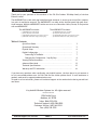
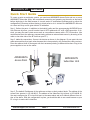
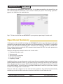
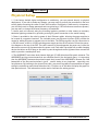
AW58300HTA
AW58300HTS
User’s Manual
5.8 GHz Outdoor 300 Mbps
Wireless Ethernet Access Point
and Subscriber Unit Radios
Industrial-grade, long-range wireless Ethernet systems
AvaLAN
W
I
R
E
L
E
S
S
AW58300HTA, HTS
User’s Manual
Thank you for your purchase of this member of the 5.8 GHz Outdoor 300 Mbps family of wireless
Ethernet radios.
The AW58300HTA is a radio with dual omnidirectional antennas. It serves as an Access Point (master)
in a point-to-multipoint network. The AW58300HTS is a radio with a dual flat panel high gain directional antenna. Multiple AW58300HTS radios can serve as a Subscriber Units (clients) in conjunction
with an AW58300HTA.
The AW58300HTA includes:
•
•
•
•
The AW58300HTS includes:
(1) AW58300HTA Access Point Radio
(1) Heavy Duty Pole-mount Bracket
(1) AW-POE-RBG Gigabit Power Over Ethernet Injector
(1) AW-PS18V 18 VDC power supply (USA plug only)
•
•
•
•
(1) AW58300HTS Subscriber Unit Radio
(1) Heavy Duty Pole-mount Bracket
(1) AW-POE-RBG Gigabit Power Over Ethernet Injector
(1) AW-PS18V 18 VDC power supply (USA plug only)
Table of Contents
Quick Start Guide . . . . . . . . . . . . . . . . . . . . . . . . . . . . . . . . . . .
Operational Summary . . . . . . . . . . . . . . . . . . . . . . . . . . . . . . .
Physical Setup . . . . . . . . . . . . . . . . . . . . . . . . . . . . . . . . . . . . .
3
5
6
Digital Configuration . . . . . . . . . . . . . . . . . . . . . . . . . . . . . . . . . . . . .
Connecting To The Radio . . . . . . . . . . . . . . . . . . . . . . . . . . . . . . .
Changing the Configuration - Step By Step . . . . . . . . . . . . . . .
Viewing Status Information . . . . . . . . . . . . . . . . . . . . . . . . . . . . . .
Advanced User Mode . . . . . . . . . . . . . . . . . . . . . . . . . . . . . . . . . .
Technical Specifications . . . . . . . . . . . . . . . . . . . . . . . . . . . . . . .
Warranty and FCC Information . . . . . . . . . . . . . . . . . . . . . . . . . . . .
7
7
8
11
13
15
16
If you have any questions when configuring your AvaLAN system, the best place to get answers is
to visit www.avalanwireless.com. You will also find the latest updates there. If more assistance is
needed, send email to [email protected].
To speak to a live technician, please call technical support at the number below during normal business hours.
© by AvaLAN Wireless Systems Inc. All rights reserved.
Revision 03.21.2013
125A Castle Drive
Madison, AL 35758
Sales: (866) 533-6216
Technical Support: (650) 384-0000
Customer Service: (650) 641-3011
Fax: (650) 249-3591
Technical Support (650) 384-0000
PAGE 2
www.avalanwireless.com
AW58300HTA, HTS
User’s Manual
Quick Start Guide
To create a point-to-multipoint system, you need one AW58300HTA Access Point and one or more
AW58300HTS Subscriber Units. We recommend connecting and powering up the units on the bench
before deploying in the field because it is much easier to troubleshoot problems and to adjust the
configuration if necessary without having to climb poles to do it. Activate the AW58300HTS units one
at a time until they can be given distinct IP addresses.
Step 1. Gather the parts: In addition to the AvaLAN radios and the accompanying AW-POE18i Power
Over Ethernet Injectors, you will need at least 4 CAT5 cables and a PC with a LAN connection. If desired, you may also want a data source such as a surveillance camera with a TCP/IP interface. (You
can determine that the radios are communicating without an external data source by browsing to the
radio on the other side of the RF link from your PC.)
Step 2. Make the connections: Connect the devices as shown in the diagram. Do not point the two
radio antennas directly at each other because their close proximity will overload the radio receivers.
Place the radios at least 10 feet apart with their antennas pointing in different directions. Plug in the
power supplies to turn on the radios.
AW58300HTA
Access Point
AW58300HTS
Subscriber Unit
Step 3. The default IP addresses of the radios are written on their product labels. The address of the
Access Point (master) is 192.168.88.12. The address of the Subscriber Unit (client) is 192.168.88.10.
You must configure your PC’s wired LAN port to the same subnet and an IP address different from either of the above. With this configuration in place, you should be able to use a web browser on your
PC to log in to each radio’s interface.
Technical Support (650) 384-0000
PAGE 3
www.avalanwireless.com
AW58300HTA, HTS
User’s Manual
Step 4. Browse to the Access Point’s interface: Enter http://192.168.88.12 into your web browser’s
address bar. If you are successful, you will see a login page like this:
click
If not, the browser will time out and you will need to double check the IP addresses and subnet
masks. If you think that the IP address of the radio has been changed, you can find it using a utility
available from the AvaLAN website. Go to www.avalanwireless.com and find the “Downloads” tab
under the “Support” menu. On the Downloads page you should find the AW58100 IP Finder Utility.
Download, unzip and run this stand alone executable. If there are any AW58100/300 family products
reachable from your PC, they will appear in a list with their MAC and IP addresses shown.
Step 5. Log In to the Access Point: The default login name is “admin” and the password is “password.”
If your login is successful, you should see the “Quick Set” page similar to this:
(You may need to scroll around in the page to see all the elements, particularly if you have a lower
resolution monitor or are using Firefox as your browser.)
If the two radios are communicating, you will see a line in the Wireless Clients section with the MAC
address of the Subscriber Unit. The Signal Strength box will indicate whether the receivers are being
overloaded. Re-position antennas if necessary to bring the signal strength below -30 dBm.
Technical Support (650) 384-0000
PAGE 4
www.avalanwireless.com
AW58300HTA, HTS
User’s Manual
Step 6. Browse to the AW58300HTS Subscriber Unit. If it is linked successfully to the Access Point, you
can do this through the wireless link. If not, connect it directly to your PC. The starting “Quick Set”
page for the Subscriber Unit looks like this:
Step 7. If there is more than one AW58300HTS in your system, repeat step 6 for each unit.
Operational Summary
Utilizing state of the art MIMO technology, the AW58300HTA/S achieves very high data rates through a
combination of dual spacial streams and higher level OFDM modulation. The default RF configuration
provides a 40 MHz channel bandwidth with 2 selectable non-overlapping channels to choose from.
When configured and mounted with HTS antennas aimed toward the HTA, the radios operate as a
wireless virtual LAN network.
These five configuration elements must be set for each radio:
1.IP address and subnet mask
2.User password
3.SSID (Service Set Identifier)
4.Encryption Pass Phrase
5.Frequency Channel
In addition to these, two more elements, a device name for your convenient reference and an Internet
Gateway Address may be set as well. For your system with an Access Point and one or more Subscriber
Units, all radios must share common SSID, Encryption Pass Phrase and Frequency Channel. The radios
are not DHCP enabled, so you will need to set unique IP addresses for each unit if you wish to browse
to them to set configuration or check status.
When the radios are configured (or left with the factory defaults), they should link automatically,
establishing virtual LAN cable connections from the Access Point to each Subscriber Unit.
Technical Support (650) 384-0000
PAGE 5
www.avalanwireless.com
AW58300HTA, HTS
User’s Manual
Physical Setup
1. If the factory default digital configuration is satisfactory, you can proceed directly to physical
deployment. If you wish to make any changes, you may want to perform the procedures in the next
section before mounting the radios in their final locations. Particularly if data security is important,
you will likely want to change passwords and encryption keys. If RF interference sources are present,
you may want to change the channel frequency or bandwidth.
2. Mount each unit securely using the mounting brackets provided or other means as necessary.
Maximize lightning resistance by providing a strong DC ground connection to the metal housing.
3. Power is provided to the units by means of their Ethernet cables, allowing the power supplies to
be located at convenient locations. The included power-over-Ethernet injectors (POE) provide the
means for adding DC power to unused wires in the cable. The POE has a power cord for connection to
a 120 VAC source, a built-in 18 VDC switching power supply and two RJ-45 sockets. Follow the connection diagram on the top of the POE. The radio connects to the end opposite the power cord, while the
data source connects to the same end as the power cord. Each radio is provided with a cable clamping
device that allows an RJ45 plug on the cable to pass through and can be tightened down around the
cable to provide a weatherproof seal.
4. The AW58300HTS units have dual element high gain (23 dBi) directional flat panel antennas. The
AW58300HTA unit has two antennas that are omnidirectional in the horizontal plane. It is important
that the AW58300HTS antennas be pointed toward their Access Point AW58300HTA. Because the 3 dB
beamwidth of the flat panel antennas is just 8°, careful aiming is very important − especially over
long distances. By browsing to the Access Point radio, you can see a graphical representation of signal
strength received from each linked Subscriber Unit. Click the row in the table to display the graph for
that particular unit. This information can be used to facilitate the aiming process.
Technical Support (650) 384-0000
PAGE 6
www.avalanwireless.com
AW58300HTA, HTS
User’s Manual
Digital Configuration
Connecting to the radio
1. Digital configuration is done by means of the radio’s built in browser interface. The unit should be
powered on and connected at least temporarily to a network containing a computer that can run a
conventional web browser.
2. Using your web browser, connect to the radio as described in the Quick Start Guide found earlier
in this manual.
3. The initial page after a successful login is “Quick Set.” The content of this page is somewhat different for the AW58300HTA Access Point and for the AW58300HTS Subscriber Unit (see the screen shots
in the Quick Start Guide).
4. Each page provides a menu on the left to navigate from section to section. The menu looks like this
when its sections are expanded:
If you wish to Logout or Reboot the radio, these functions are available in this menu.
Beware that certain actions may cause the web page to freeze. In most cases, this is because you are
viewing a browser-cached version of the page and not the live one from the radio. Clear your browser
cache and/or logout and log back in to recover. You are cautioned not to use the “back” button on
your browser to attempt to move back to earlier pages. If you do, you will be logged out and will
need to login again.
In the upper right of the page is a label that tells you the version of the web interface. If the version number is not the same as shown below, you might want to visit www.avalanwireless.com (the
Downloads page under the Support menu) to see if a newer version of this manual exists before proceeding further.
Technical Support (650) 384-0000
PAGE 7
www.avalanwireless.com
AW58300HTA, HTS
User’s Manual
Changing The Configuration - Step by Step
Please be aware that if you change the IP Address or User Password and forget their new values, you
have locked yourself out of the browser interface. The AW58300 runs self-diagnostics at boot-up and
will auto-correct most system configuration errors. Prior to calling technical support, it is recommended to power cycle the radio and confirm that the problem remains.
In the event of a lost IP address, the AW58300 has a permanent factory IP address of 192.168.88.88
that can be used to access the radio to reset the user-defined IP address. In the event of a lost password, please contact AvaLAN technical support for assistance.
If you are changing parameters over the RF link (we do not recommend this), be sure to make the
remote changes first because the link will be broken if the SSIDs or Security Keys do not agree.
1. Setting the IP Address and Subnet Mask, Gateway and Device Name:
•In the upper right area of the Quick Set page are the data entry boxes for these parameters.
They contain the current values.
•A special notation is used for the IP Address and Subnet Mask: Use /x at the end of the
IP Address to specify the subnet mask: /8 for 255.0.0.0, /16 for 255.255.0.0 and /24 for
255.255.255.0. Enter a new IP Address and subnet making sure you will be able to browse to
the new address with your computer. Also, make sure that the new IP address is unique on your
LAN.
•The Gateway address should be specified if it is necessary to communicate with the radio
through the Gateway. Your system administrator should have this value.
•The Device Name is an arbitrary string and simply allows you to attach a human-friendly name
to this specific radio.
•Click “Apply Configuration” when you have entered new values. Nothing appears to happen, but
you have been disconnected and will need to browse to the new IP Address to login again.
Technical Support (650) 384-0000
PAGE 8
www.avalanwireless.com
AW58300HTA, HTS
User’s Manual
2. Setting the User Password:
•On the Main Menu at the left side of the browser window, click “System”, then click
“Password.”
•Enter the old password and the new password twice in the boxes indicated.
•Click the “Change” button.
•Log out and log back in to test.
3. Setting the Channel Width, Frequency, SSID and AES Encryption Key:
•On the Main Menu at the left side of the browser window, click “Wireless.” This loads the
Wireless Tables page. This page has two tabs at the top, “Interfaces” and “Associations.”
•The table on the Interfaces tab looks a bit different for an Access Point vs. a Subscriber Unit.
The Access Point will have a row named “Wireless_Radio” and one “wds” row for each linked
Subscriber Unit. The Subscriber Unit will only have the “Wireless_Radio” row.
•Click anywhere in the Wireless_Radio row to drill down to the “Interface <Wireless Radio>”
page. Do not click the small “D” button unless you want to disable the radio, requiring power
cycling to recover.
•On this new page are data entry boxes for Channel Width, Frequency, SSID and AES Encryption
Key.
Technical Support (650) 384-0000
PAGE 9
www.avalanwireless.com
AW58300HTA, HTS
User’s Manual
•The Channel Width should be left at 20/40 MHz HT Above. This is the only supported option for
this product.
•The Frequency dropdown box provides many more choices than are useful (or even legal). The
only supported choices here are 5805 MHz (the default) or 5745 MHz.
•The SSID is an arbitrary character string that must be set alike in all linked radios.
•The AES Encryption Key is also an arbitrary character string that is used to generate the 128 bit
key. It must be set alike in all linked radios and normal best practice for choosing passwords
should be applied when setting this key.
•When you have entered your choices in the boxes, click the “Apply” button near the top of the
page. The radio will reboot and you will need to login again to see the changes.
Technical Support (650) 384-0000
PAGE 10
www.avalanwireless.com
AW58300HTA, HTS
User’s Manual
Viewing Status Information
After configuring your AvaLAN radios and establishing links among them, you can use the browser
interface to view status and troubleshooting Information. The initial “Quick Set” page will show
whether the wireless link is operating and the current signal strength. For more comprehensive information, choose “Wireless” from the Main Menu at the left side of the window. The “Wireless” page
leads to most of the useful status information.
The table on the Interfaces tab provides a list of the interface processes running in this radio. If it is
a Subscriber Unit, there will be only one, “Wireless_Radio.” If it is an Access Point, there will also be
a WDS process running for each Subscriber Unit that is connected. These very long rows summarize
the configuration details and current running status of the radio. You can click and drag in the heading
row of the table to change the column width if part of the data is not visible.
More detailed status: Do not click the small “D” button unless you want to disable the radio, requiring power cycling to recover. Clicking anywhere else on the “Wireless_Radio” line drills down to more
information:
Technical Support (650) 384-0000
PAGE 11
www.avalanwireless.com
AW58300HTA, HTS
User’s Manual
Most of the information on the top part of this page was covered in the Digital Configuration section
of this manual. The status information in the lower part of the page is mostly self-explanatory. Here
are a few additional notes:
•Tx/Rx Rate shows the current instantaneous values in kilobits per second. The Byte graph below
shows the history of the same information.
•Tx/Rx Packet rate and graph show packets per second transmitted and received.
•Tx/Rx Bytes and Packets show total values accumulated since the last Reboot.
•Tx/Rx Drops are packets not sent or received because of the radio’s interface queue being full.
•Tx/Rx Errors are packets sent or received with unrecovered data errors.
This status page for the Access Point shows the total traffic with all connected Subscriber Units. To see
individual data, return to the Wireless page and click anywhere in the WDS row for that Subscriber
Unit.
By logging into a Subscriber Unit directly and going to the Wireless page and then clicking in the
“Wireless_Radio” row, some additional status information is available that does not appear on the
corresponding Access Point page:
In the “Status” section, the Tx/Rx Rate shown is the raw RF rate calculated based on the Channel
Width and modulation scheme in use. The above screen shot shows that the radio is transmitting and
receiving with 64-QAM and a 5/6 Coding Rate. The RF rate your link can achieve depends upon distance, signal to noise ratio and interference sources.
The Tx/Rx CCQ (Client Connection Quality) is a value in percent that shows how effectively the theoretical maximum bandwidth is being used. This is measured by taking an average of Tmin/Treal, where
Tmin is the theoretical minimum time to transmit a frame and Treal is the actual time.
Technical Support (650) 384-0000
PAGE 12
www.avalanwireless.com
AW58300HTA, HTS
User’s Manual
Advanced User Mode
There is an alternate login mode that provides two occasionally useful functions that are not available to the normal user. These functions allow the Advanced User to update the radio’s firmware and
to perform a bandwidth self test.
To enter this mode, log in to the radio using the user name “adv_user” and a password of “passw0rd”
(replace the “o” with a zero).
The initial Quick Set page has two differences, a menu addition and a “Upgrade” file entry box:
From time to time, AvaLAN may update the firmware for your radio. If this happens, the new version
may be downloaded from www.avalanwireless.com by visiting the Downloads page under the Support
Menu tab. Download the update, follow the instructions in the readme file and install the proper file
by choosing it in the File entry box and clicking “Apply Configuration.”
The Main Menu has a “Tools” tab and under it, “Bandwidth Test.” Clicking this brings up this new
page:
Technical Support (650) 384-0000
PAGE 13
www.avalanwireless.com
AW58300HTA, HTS
User’s Manual
The Bandwidth Test is essentially a ping flood and may be performed with any device but is usually
performed on the radio on the other end of the RF link. To run a test, do the following:
•Enter the IP address of the device to exchange data with (usually the IP address of the other
radio).
•Choose the Protocol, udp or tcp. You will achieve higher data rates with udp packets because
they are smaller.
•Choose the direction: Transmit, Receive or Both.
•Click “Start.”
The test will run continuously until you click “Stop.” Be sure to do this before leaving the page or the
test may continue to run and disrupt normal use of the wireless link.
The data rates are displayed numerically, current, 10 second average, or total test average. There is
a graph on the lower part of the Bandwidth Test page, but it does not function.
If you are testing the wireless link, you can login to the other radio as a normal user, go to the
“Wireless” page and click the “Wireless_Radio” row to see the data rate graphically from the other
end. Here is an example, showing several tests performed in sequence:
udp Transmit Test
udp Receive Test
(Tx from this end)
Technical Support (650) 384-0000
PAGE 14
tcp Receive Test
udp Both Test
www.avalanwireless.com
AW58300HTA, HTS
User’s Manual
Technical specifications
CHARACTERISTIC
SPECIFICATION/DESCRIPTION
RF Data Rate
Up to 300 Mbps
Output power AW58300HTA Access Point 1 Watt EIRP with 6 dBi omnidirectional antenna
Output power AW58300HTS Subscriber
Unit
4 Watts EIRP with 23 dBi directional antenna
Receiver Sensitivity
-115 dBm for HTS and HTP configurations, -101 dBm for the HTA
Frequency Range
5.725 - 5.850 GHz
Channel Bandwidth
20/40 MHz HT Above
RF channels
2 Non-Overlapping with 40 MHz Channel Bandwidth, 5.745 GHz
or 5.805 GHz
Modulation
OFDM (BPSK, QPSK, 16-QAM, 64-QAM)
Range
Line-of-sight range up to 15 miles for AW58300HTP-PAIR Bridge,
5 miles for HTA/HTS point-to-point configuration
Browser Management Tools
Data Communication Statistics, Network Settings, Channel
Selection
Data Security
AES 128-bit
Operating Environment
-40ºC to +70ºC, sealed for outdoor operation:
die cast aluminum package with rubber gasket seals
Mounting
Heavy Duty Pole-Mount Bracket included
Connector
AW58300HTA Antenna
10/100/1000 base T Ethernet RJ-45 with weatherproof sealing
gland
CAT6a Outdoor/Direct Burial
Gigabit Power Over Ethernet Injectors and 18 VDC power supplies included: 120 VAC 60Hz primary source
Omnidirectional, 6 dBi gain in horizontal plane, 12” long
AW58300HTA Size
8.75” Square by 3.25” case plus 12” tall antenna, weight 7 lbs
AW58300HTS Antenna
Integrated 23 dBi flat panel, dual quadrature elements, 15.2”
square, 3 dB Beamwidth 8°
AW58300HTS Size
15.2” by 15.2” by 3.25”, not including pole-mount bracket,
weight 7 lbs
Warranty
1 Year Parts & Labor, XTRa-Care Extended Warranty 2 Year Extension available at nominal cost
Certification
FCC, IC
Recommended LAN Cable
Power System
Technical Support (650) 384-0000
PAGE 15
www.avalanwireless.com
AW58300HTA, HTS
User’s Manual
Limited Warranty
This product is warranted to the original purchaser for normal use for a period of 360 days from the
date of purchase. If a defect covered under this warranty occurs, AvaLAN will repair or replace the
defective part, at its option, at no cost. This warranty does not cover defects resulting from misuse
or modification of the product.
If you wish, you may purchase extended warranty for this product. AvaLAN’s XTRa-Care Extended
Warranty provides a two-year extension plus free overnight (Continental USA only) product replacement. Visit our website for more details.
Regulatory Compliance
Technical Support (650) 384-0000
PAGE 16
www.avalanwireless.com