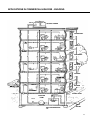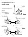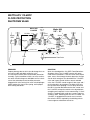
1
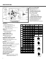
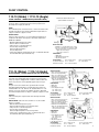
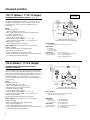
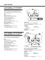
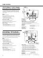
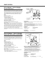
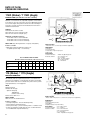
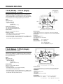
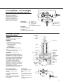
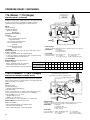
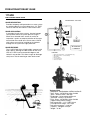
Automatic Control Valves
The Automatic
Answer to
Fluid Control
watts.com
INTRODUCTION
Specifying Automatic Control Valves is a critical balancing act. On one
hand, you must have the utmost confidence not only in
the quality and performance of the valve, but also in
the knowledge and “hands-on” expertise of the manufacturer. On the other hand, product reliability
must be unquestioned, meeting the exact design
parameters specified. Orders must be
shipped as promised, keeping your job on
track, and after-the-sale support is essential. You can count on Watts ACV to deliver
the highest quality Automatic Control Valves
available, and service second to none.
Our factory trained Representatives offer detailed specification assistance, analyzing system conditions to recommend the right valve for
your application. System, material, and application considerations are
reviewed, so the right control valve is selected for your project. You
can be confident that Watts ACV and our local Representatives are
ready and able to assist your design team.
With a long history of service in Commercial Plumbing, Municipal
Waterworks, Fire Protection, Irrigation, Aviation Fueling, Marine,
Theme Park, Decorative Fountain, Light Industrial, and Reclaimed
Water markets, Watts ACV has the expertise and products to meet
your needs. Since the 1960’s, Watts ACV has kept pace with changing
market requirements, developing and delivering quality Automatic
Control Valves at affordable prices.
Our fusion bonded, epoxy coated, ductile iron Automatic Control
Valves offer long life and minimal maintenance. And for harsh applications and environments, our Fabricated Stainless Steel Valves provide
a cost effective solution.
Whether your application requires Pressure, Level, Pump, or Flow
Control, Watts ACV is your best choice for Selection, Sales, and Service.
Watts ACV. The Automatic Answer to Fluid Control.
2
TABLE OF CONTENTS
Page
Table of Contents . . . . . . . . . . . . . . . . . . . . . . . . . . . . . . . . .3
The More You Know . . . . . . . . . . . . . . . . . . . . . . . . . . . . . . .4
Competitive Cross Reference Chart . . . . . . . . . . . . . . . . . .5
Specifications . . . . . . . . . . . . . . . . . . . . . . . . . . . . . . . . . . .6
Float Control Valves
ACV 110-10 Modulating Float . . . . . . . . . . . . . . . . . . . . . . . .7
ACV 110-14 On-Off/Adjustable Hi-Lo Level . . . . . . . . . . . . . .7
Solenoid Control Valves
ACV 113-12 On-Off . . . . . . . . . . . . . . . . . . . . . . . . . . . . . . . .8
ACV 113-6 On-Off/High Capacity Controls . . . . . . . . . . . . . . .8
Pump Control Valves
ACV 113-46 Booster Pump Control 11/4-4" . . . . . . . . . . . . . .9
ACV 113-21 Booster Pump 6-16" . . . . . . . . . . . . . . . . . . . . .9
ACV 413-21 Booster/Lift Check . . . . . . . . . . . . . . . . . . . . . .10
ACV 513-5 Booster/Dual Chamber/Check . . . . . . . . . . . . . .10
ACV 513-6 Deep Well . . . . . . . . . . . . . . . . . . . . . . . . . . . . .11
ACV 513-12 Booster/Dual Chamber . . . . . . . . . . . . . . . . . . .11
Page
Check Valves
ACV 118-3R Check w/ Opening & Closing Speed . . . . . . . . .17
Altitude Valves
ACV 127-1 One Way Flow . . . . . . . . . . . . . . . . . . . . . . . . . .18
ACV 127-2 Two Way Flow . . . . . . . . . . . . . . . . . . . . . . . . . .18
ACV 127-11 One Way Flow/Delayed Opening . . . . . . . . . . . .18
ACV Fire Protection Valves
ACV 115F Pressure Reducing Valve . . . . . . . . . . . . . . . . . . .19
ACV 116FM Fire Pump Relief . . . . . . . . . . . . . . . . . . . . . . . .20
ACV 116-1FM Fire Pump Suction . . . . . . . . . . . . . . . . . . . . .20
ACV 100D-A Deluge/Hydraulic/Pneumatic . . . . . . . . . . . . . .21
ACV 100D-B Deluge/Electronic . . . . . . . . . . . . . . . . . . . . . .21
Fire Hydrant Relief Valve
ACV 1116FH . . . . . . . . . . . . . . . . . . . . . . . . . . . . . . . . . . . .22
Applications in Commercial High Rise - Building . . . . . .23
Downstream Expansion Relief Valve
ACV 116-BYR . . . . . . . . . . . . . . . . . . . . . . . . . . . . . . . . . . . .24
Rate of Flow Valves
ACV 114R Rate of Flow . . . . . . . . . . . . . . . . . . . . . . . . . . . .12
Flood Protection Shutdown Valve
ACV 113-6RFP . . . . . . . . . . . . . . . . . . . . . . . . . . . . . . . . . . .25
Pressure Reducing Valves
ACV 115 Pressure Reducing . . . . . . . . . . . . . . . . . . . . . . . .12
ACV 115-2 Pressure Reducing/Sustaining . . . . . . . . . . . . . .13
ACV 115-3 Pressure Reducing/Check . . . . . . . . . . . . . . . . .13
ACV 115-4 Pressure Reducing/Solenoid . . . . . . . . . . . . . . .14
ACV 115-7 Pressure Reducing/Surge . . . . . . . . . . . . . . . . . .14
Industrial Control Valves
Applications . . . . . . . . . . . . . . . . . . . . . . . . . . . . . . . . . . . . .26
Pressure Reducing/Low Flow By-Pass Valve
ACV 115-74 Pressure Relief/Sustaining . . . . . . . . . . . . . . . .15
Figure PV20CB . . . . . . . . . . . . . . . . . . . . . . . . . . . . . . . . . . .15
Pressure Relief and Sustaining Valves
ACV 116 Pressure Relief/Sustaining . . . . . . . . . . . . . . . . . . .16
ACV 116-31 Pressure Sustaining/Solenoid . . . . . . . . . . . . . .16
ACV 116-52 Surge Anticipator Relief . . . . . . . . . . . . . . . . . .17
Irrigation ACV Valves
813 Series . . . . . . . . . . . . . . . . . . . . . . . . . . . . . . . . . . . . . .27
ENGINEERING DATA . . . . . . . . . . . . . . . . . . . . . . . . . . .28-30
VALVE SIZING . . . . . . . . . . . . . . . . . . . . . . . . . . . . . . . . . . .31
Pressure Reducing Sizing . . . . . . . . . . . . . . . . . . . . . . . . . .32
Cavitation Chart . . . . . . . . . . . . . . . . . . . . . . . . . . . . . . . . . .32
Submittal/Specification . . . . . . . . . . . . . . . . . . . . . . . . . . .33
Spare Parts List . . . . . . . . . . . . . . . . . . . . . . . . . . . . . . . . .34
How To Order . . . . . . . . . . . . . . . . . . . . . . . . . . . . . . . . . . .35
Agent Listing . . . . . . . . . . . . . . . . . . . . . . . . . . . . . . . . . . .36
3
THE MORE YOU KNOW ABOUT AUTOMATIC CONTROL VALVES
THE BETTER WATTS ACV LOOKS!
Performance is standard
The design and innovative features incorporated into
every Watts Automatic Control Valve means consistent,
dependable, high performance, positive control and
long life.
Efficient design
The main valve, globe or angle pattern, is diaphragm
actuated, hydraulically operated. It consists of only four
major components. The body and cover plus interior
seat and diaphragm/stem assembly, which is the only
moving part in the main valve.
Variable volume cover chamber
STEM
DIAPHRAGM
WASHER
STEM NUT/WASHER
DIAPHRAGM
SPACER
QUAD SEAL RETAINER
QUAD SEAL
RETAINER PLATE
QUAD SEAL
STEM ASSEMBLY
A synthetic rubber/nylon diaphragm, of FDA approved
materials, is assembled between the valve body and
cover. This creates a sealed chamber into which line
fluid and pressure is introduced. Varying the amount of
pressure accurately positions the stem assembly to
open, close or modulate the valve as required.
Precise alignment
and stable throttling
A cover bearing and integral seat bearing guide the
stem assembly for precise alignment with the seat.
Coupled with the quad seal retainer plate, this alignment assures progressive opening/closing flows, stable
throttling, low friction operation and positive closure.
Drip tight seal
Watts ACV leads the automatic valve industry by being
the first to incorporate the dynamic quad seal. The seat,
retained on 3 1/2+ sides, provides positive closure
while eliminating the need to “bite” into the seal, adding
years to the valve’s life. Each quad seal has two usable
sides.
Fused epoxy prolongs life
This coating is applied under rigorous preparation and
application standards. It is non-porous, improving the
flow coefficiency of the valve and effectively sealing the
casting from interaction with the controlled liquid. The
coating also protects the valve from environmental
attack. The finish prevents mineral buildup and rust (a
major factor in control valve failure), simplifies maintenance, and prolongs the life of the valve.
Multiple function performance
ACV 115
PRESSURE REDUCING
ACV 116
PRESSURE RELIEF/SUSTAINING
By varying the control/piping arrangement, the Watts
ACV is able to perform a diversity of functions and
applications. Multiple functions performed by a single
valve can result in added system protection and lower
cost to the user.
Simplified Maintenance
The main valve and pilot system can be serviced without removing the valve from the line.
Right valve, Right place, Right time
ACV 127-1
ALTITUDE VALVE - ONE WAY FLOW
4
Watts ACV is committed to providing you with correct
function and material to meet your application
requirements and prides itself with accurate, calculated
delivery schedules.
COMPETITIVE CROSS-REFERENCE GUIDE
Watts ACV
Model No.
Cla-Val
Model No.
114
40-01
Rate of Flow Control Valve
116
50-01
Pressure Relief Control Valve
Description
116-5
50-01D
116-52
52-03
Surge Anticipator Control Valve
Pressure Sustaining and Check Valve
116-31
58-01
Pressure Sustaining and Solenoid Shutoff
513-5
60-11
Dual Chamber Booster Pump Control Valve
413-21
60-31
Single Chamber Booster Pump Control Valve
513-6
61-02
Deep Well Pump Control Valve
118-3
81-02
Non-Surge Check Valve (Opening / Closing Speed Controls)
115
90-01
Pressure Reducing Control Valve
115-3
90-01D
115-2
92-01
Pressure Reducing and Pressure Sustaining Control Valve
115-4
93-01
Pressure Reducing and Solenoid Shutoff
110-14
124-01
On - Off Float Valve (6" and smaller)
110-14
124-02
On - Off Float Valve (8" and larger)
110-10
129-01
Modulating Float Valve
113-12
136-01A
113-6
136-03ABC
127-1
210-01
One Way Flow Altitude Control Valve
127-2
210-06
Two Way Flow Altitude Control Valve
127-11
210-03
One Way Flow Altitude Control Valve (delayed opening)
Pressure Reducing and Check Valve
Solenoid Control Valve (3" and smaller)
Solenoid Control Valve (w/High Capacity Controls)
5
SPECIFICATIONS
WATTS ACV FEATURES
Standard Production Valves:
* Wide range of sizes 1 1/4" - 24"
* Fused epoxy coating 100% inside
and out. (FDA and NSF approved,
Meets AWWA standards)
* Exclusive “QUAD SEAL”
- retained on 3 1/2 + sides
- positive drip-tight closure
- longer life span (non-edged seat)
* Diaphragm actuated (one moving part)
* FDA approved diaphragm materials
* Hydraulically operated (frictionless)
* Top and bottom guided stem
* Packless construction (less maintenance)
BASIC VALVE
* Body and Cover
Ductile Iron: ASTM A536 65-45-12
Fused Epoxy Coated 100% inside/outside
* Seat - Stainless Steel - AISI 316 - 11/4" - 8"
Bronze ASTM B62 - 10" - 24"
Optional: Stainless Steel - AISI 316 - 10" - 24"
* Stem - Stainless Steel - AISI 303
* Spring - Stainless Steel - AISI 302
* Elastomers
Diaphragm: Nylon reinforced BUNA-N (Nitrile)
"Quad Seal”: BUNA-N (Nitrile)
Other materials available
HYDRAULIC CONTROL PILOTS
* Bodies: ASTM B584, Alloy C84400
* Internals: Stainless Steel - AISI 303
* Elastomers: BUNA-N (Nitrile)
Other materials available
VALVE
SIZE
1 1/4
1 1/2
2
2 1/2
3
MISCELLANEOUS CONTROL ACCESSORIES
* Bodies: Brass - ASTM B584, Alloy C84400
* Internals: Stainless Steel - AISI 303
* Elastomers: (where applicable): BUNA-N (Nitrile)
Other materials available
4
ELECTRICAL
* 120 VAC, 60 Hz, Optional voltage available
* Body: Brass, Optional: Stainless Steel
* Enclosure: General Purpose (NEMA Type 1, 2, 3, 3S, 4, 4X)
Optional: Explosion proof (NEMA Type 3, 3S, 4, 4X, 6P, 7, 9)
8
CONTROL CIRCUIT STRAINER
11/4"-3" In-line, Flo-clean, Optional: Isolation Cocks
4-24" External, “Y” strainer + Isolation Cocks
(unless noted on drawing)
CONTROL TUBING/FITTINGS
* Copper, seamless annealed/Brass flared end
Optional: Stainless Steel / Stainless Steel
OPERATING TEMPERATURES (BUNA-N)
* Water: +32 degrees to 180 degrees F
END CONNECTIONS/MAXIMUM
WORKING PRESSURE
Ductile Iron: 150# F.F. Flange: ANSI B16.42 / 250 PSIG
300# R.F. Flange: ANSI B16.42 / 400 PSIG
Threaded: ANSI B16.4 / 400 PSIG
6
6
10
12
14
16
18
20
24
DIMENSION
A
E
F
A
E
F
A
E
F
A
E
F
A
E
F
A
E
F
A
E
F
A
E
F
A
E
F
A
E
F
A
E
F
A
E
F
A
A
A
GLOBE FLANGED
150#
300#
ANGLE FLANGED
150#
300#
GLOBE
THREADED
7 1/4
ANGLE
THREADED
3 1/4
1 7/8
8 1/2
9 3/8
11
12
15
20
25 3/8
29 3/4
34
39
9
7.25
4
4
4 1/4
4 1/4
4
4
4 1/4
4 1/4
5 1/2
4
5 13/16
4 5/16
5 3/4
5 3/4
6 1/8
6 1/8
6 3/4
6 3/4
7 1/8
7 1/8
8 1/2
8 1/2
878
8 7/8
11
11
11 1/2
11 1/2
14 7/8
14 7/8
15 5/8
15 5/8
17
17
17 3/4
17 3/4
10
9 3/8
11 5/8
48
48
48 1/4
4
4
11
5 1/2
4
13 1/4
15 5/8
21
26 3/8
31 1/8
35 1/2
40 1/2
CONSULT CONSULT
CONSULT CONSULT
41 3/8
3 1/4
1 7/8
43 1/2
49 5/8
49 5/8
50
CONSULT
CONSULT
CONSULT
CONSULT
CONSULT
CONSULT
CONSULT
CONSULT
CONSULT
CONSULT
A = 10 1/2
E = 5 1/4
F = 5 1/4
FLOAT CONTROL
110-10 (Globe) / 1110-10 (Angle)
FLOAT CONTROL – MODULATING (CONSTANT LEVEL)
➡ CLOSES VALVE
Flow Direction Shown: Under the Seat
Optional ‘R’ Flow Over the Seat:
➪ OPENS VALVE
The ACV 110-10 maintains a constant level in storage tanks and
reservoirs. Valve controlled flow into the tank is proportional to
discharge flow, keeping the tank full.
NOTE:
The modulating float control ACV 10-11, is remote mounted. A stilling well around the float should be installed if the liquid surface is
subject to turbulence, ripples or wind.
QUICK SIZING:
Valve size same as fill line or one size smaller if discharge line is
smaller than fill. Match size/capacity to discharge requirements.
Points to consider:
– Minimum differential pressure 5 psig
– Refer to table for maximum flow
– Inlet pressure vs. tank head pressure
– Pressure drop at required flow
Refer to Engineering Data –
Pressure Drop Chart
– If valve size required is smaller than line size, consider ACV 6110-10.
Consult Watts ACV representative/factory
VALVE FUNCTION
– Maintains a constant liquid level in a tank.
– Remote mounted pilot is sensitive to slight
changes in level and controls main valve:
Opens when level drops
Closes when level rises
COMPONENTS
1. Main Valve
2. Modulating Float Control
3. Adj. Closing Speed
ACCESSORIES
Located as indicated
Included as marked
❏ X - Isolation Cocks
❏ Y -Y - Strainer
❏ P - Position Indicator
❏ FC - Flo-Clean Strainer
❏ L - Limit Switch
4" & Smaller
110-14 (Globe) / 1110-14 (Angle)
FLOAT CONTROL – ON/OFF (OPEN/CLOSE) ADJ. HI/LO LEVEL
The ACV 110-14 opens fully when the level reaches the preset low
point and shuts off drip tight when the high level is reached. The
rotary 3-port pilot is equipped with a vertical rod which allows the
float to rise and lower to the adjustable upper and lower stops.
NOTE:
The pilot is remote mounted unless specified valve mounted.
Standard equipped with brass rods and plastic float. Valve 2-6"
standard with 2-12" rods. Valves 8-16" standard with 4-12" rods.
Stainless steel rods and float are available. Provide a stilling well
around float if liquid surface is subject to turbulence, ripples or wind.
SPECIFY:
Valve mounted pilot is required, and valve discharge horizontal
or vertical.
QUICK SIZING: Valve size same as fill line or one size smaller.
Points to consider:
– Minimum differential pressure 5 psig
– Refer to Engineering Data – Flow Capacity Chart
– Inlet pressure vs. tank head pressure
– Pressure drop at required flow
Refer to Engineering Data – Pressure Drop Chart
– If valve size is smaller than line size, consider ACV 6110-14
Consult Watts ACV representative/factory
VALVE FUNCTION
– Valve opens when float reaches
lower level stop (adjustable)
– Valve closes when float reaches
upper level stop (adjustable)
– High and low level adjustments
allows for calculated draw down
Opens when level drops
Closes when levels rises
COMPONENTS
1. Main Valve
2. Float Pilot
3. Level Adjustment Stops
3A – Upper Level
3B – Lower Level
ACCESSORIES
Located as indicated
Included as marked
❏ X - Isolation Cocks
❏ Y -Y - Strainer
❏ P - Position Indicator
❏ FC - Flo-Clean Strainer
❏ L - Limit Switch
VALVE FUNCTION
6" & Larger
– Valve opens when float reaches
lower level stop (adjustable)
– Valve closes when float reaches
upper level stop (adjustable)
– High and low level adjustments
allows for calculated draw down
Opens when level drops
Closes when levels rises
COMPONENTS
1. Main Valve
2. Float Pilot
3. Level Adjustment Stops
3A – Upper Level
3B – Lower Level
4. Accelerator
5. Adj. Closing Speed
6. Adj. Opening Speed
ACCESSORIES
❏ X - Isolation Cocks
❏ FC - Flo-Clean Strainer
Located as indicated
❏ Y -Y - Strainer
❏ L - Limit Switch
Included as marked
❏ P - Position Indicator
7
SOLENOID CONTROL
113-12 (Globe) / 1113-12 (Angle)
➡ CLOSES VALVE
➪ OPENS VALVE
1 4
SOLENOID ON/OFF (OPEN/CLOSE) Sizes 1 / " - 4"
Operated by a 3-way solenoid, the main valve opens fully or closes
drip-tight depending upon the actuation position of the solenoid,
energized to open/energized to close. The valve may be remotely
operated by timers, relays, probes or any triggered device to
the solenoid.
NOTE:
Energized to open valve.
Optional: energized to close valve.
At time of order, advise factory actual system working pressure
for correct solenoid selection.
110-120 VAC, 50-60 Hz standard
Optional: specify voltage required.
Enclosure General Purpose (NEMA 1, 2, 3, 3S, 4, 4X)
Optional: explosion proof (NEMA 3, 3S, 4, 4X, 6, 6P, 7, 9)
Manual operator standard
Optional: Opening and/or closing speed.
QUICK SIZING: Valve size same as line or one size smaller.
Points to consider:
– Refer to Engineering Data - Flow Capacity Chart
– Pressure drop at required flow
Refer to Engineering Data - Pressure Drop Chart
– If valve size required is smaller than line size, consider ACV 6113-12
Consult Watts ACV representative/factory
Flow Direction Shown: Under the Seat
Optional ‘R’ Flow Over the Seat: 113-12R/1113-12R
VALVE FUNCTION
–Electrically operated on/off (open/close) control valve
COMPONENTS
1. Main Valve
2. 3-Way Solenoid
3. Flo-Clean Strainer
❏
❏
❏
❏
ACCESSORIES
Located as indicated
Included as marked
X - Isolation Cocks
Y -Y - Strainer (Eliminates Flo-Clean)
ACS - Adj. Closing Speed
ADS - Adj. Opening Speed
113-6 (Globe) / 1113-6 (Angle)
SOLENOID ON/OFF (OPEN/CLOSE) WITH HIGH
CAPACITY CONTROLS
A 3-way solenoid and auxiliary 3-port accelerator cause the main
valve to open fully or close drip-tight depending upon the actuation
position of the solenoid, energized to open/energized to close. The
high capacity accelerator assures quick valve response to the solenoid signal regardless of the main valve size. The valve may be
remotely operated by timers, relays, probes or any triggering device
to the solenoid.
NOTE:
Energized to open valve.
Optional: energized to close valve.
At time of order, advise factory actual system
working pressure for correct solenoid selection.
110-120 VAC, 50-60 Hz standard
Optional: specify voltage required.
Enclosure General Purpose (NEMA 1, 2, 3, 3S, 4, 4X)
Optional: explosion proof (NEMA 3, 3S, 4, 4X, 6, 6P, 7, 9)
Manual operator standard
Standard with adjustable opening and closing speed.
QUICK SIZING: Valve size same as line or one size smaller.
Points to consider:
– Refer to Engineering Data - Flow Capacity Chart
– Pressure drop at required flow
Refer to Engineering Data - Pressure Drop Chart
– If valve size required is smaller than line size, consider ACV 6113-12
Consult Watts ACV representative/factory
8
Flow Direction Shown: Under the Seat
Optional ‘R’ Flow Over the Seat: 113-6R/1113-6R
VALVE FUNCTION
–Electrically operated on/off (open/close) control valve
–High capacity control for fast response
COMPONENTS
1. Main Valve
2. 3-Way Solenoid
3. Flo-Clean Strainer
ACCESSORIES
Located as indicated
Included as marked
4. Adj. Closing Speed
5. Adj. Opening Speed
6. Accelerator Control
❏
❏
❏
❏
X - Isolation Cocks
Y -Y - Strainer (Eliminates Flo-Clean)
L - Limit Switch
P - Position Indicator
PUMP CONTROL
113-46 (Globe) / 1113-46 (Angle)
BOOSTER PUMP CONTROL (Valves 4" and smaller)
Solenoid operated pump control for controlled opening and closing
on pump start-up and shut-down. Equipped with hydraulic check
feature to close valve on pressure reversal and shut-off pump
in event of pump failure. Valve and pump operations are interlocked
by a limit switch assembly.
NOTE:
Energized to open valve.
At time of order, advise factory actual system
working pressure for correct solenoid selection.
110-120 VAC, 50-60 Hz standard
Optional: specify voltage required.
Solenoid enclosure NEMA 1, 2, 3, 3S, 4, 4X
Manual operator standard
Limit switch enclosure general purpose
Standard with adjustable opening and closing speed.
Additional combinations:
413-46 Pump Control/Lift-Check
QUICK SIZING: Valve size same as line.
Points to consider:
– Refer to Engineering Data - Flow Capacity Chart
– Pressure drop at required flow
Refer to Engineering Data - Pressure Drop Chart
➡ CLOSES VALVE
➪ OPENS VALVE
Flow Direction Shown: Under the Seat
Optional ‘R’ Flow Over the Seat: 113-46R/1113-46R
VALVE FUNCTION
– Opens at a controlled rate on pump start-up (adjustable)
– Closes at a controlled rate on pump shut-off (adjustable)
– Valve and pump are electrically interlocked so that power is shut-off when
the valve is in near closed position
COMPONENTS
1. Main Valve
2. 3-Way Solenoid
3. Fig. 51 Limit Switch
4. Adj. Opening Speed
ACCESSORIES
Located as indicated
Included as marked
5. Adj. Closing Speed
6. Check Valve
FC – Flow CLean Strainer
❏ X - Isolation Cocks
❏ Y -Y - Strainer
113-21 (Globe) / 1113-21 (Angle)
BOOSTER PUMP CONTROL (Valves 6" and larger)
Solenoid operated pump control for controlled opening and closing
on pump start-up and shut-down. Equipped with hydraulic check
feature to close valve on pressure reversal. Valve and pump
operations are interlocked by a limit switch assembly.
NOTE:
Energized to open valve.
At time of order, advise factory actual system
working pressure for correct solenoid selection.
110-120 VAC, 50-60 Hz standard
Optional: specify voltage required.
Solenoid enclosure NEMA 1, 2, 3, 3S, 4, 4X
Manual operator standard
Limit switch enclosure general purpose
Standard with adjustable opening and closing speed.
QUICK SIZING: Valve size same as line.
Points to consider:
– Refer to Engineering Data - Flow Capacity Chart
– Pressure drop at required flow
Refer to Engineering Data - Pressure Drop Chart
VALVE FUNCTION
– Opens at a controlled rate on pump start-up (adjustable)
– Closes at a controlled rate on pump shut-off (adjustable)
– Valve and pump are electrically interlocked so that power is shut-off when
the valve is in near closed position
– Check feature closes valve when discharge pressure exceeds inlet pressure
(power failure or pump failure)
COMPONENTS
1. Main Valve
2. Accelerator Control
3. Figure 51 Limit Switch
4. 3-Way Solenoid
ACCESSORIES
Located as indicated
Included as marked
5. Check Valve
6. Adj. Closing Speed
7. Adj. Opening Speed
❏ X - Isolation Cocks
❏ FC - Flo-Cleaner Strainer
❏ Y -Y - Strainer
9
PUMP CONTROL
413-21 (Globe) / 1413-21 (Angle)
BOOSTER PUMP CONTROL / MECHANICAL LIFT CHECK
Solenoid operated pump control for controlled opening and closing
on pump start-up and shut-down. Equipped with mechanical liftcheck feature to close valve the moment flow stops, preventing
reverse flow. Valve and pump operations are interlocked by a limit
switch assembly.
NOTE:
Energized to open valve.
At time of order, advise factory actual system
working pressure for correct solenoid selection.
110-120 VAC, 50-60 Hz standard.
Optional: specify voltage required.
Solenoid enclosure NEMA 1, 2, 3, 3S, 4 4X.
Manual operator standard
Limit switch enclosure general purpose
Standard with adjustable opening and closing speed.
QUICK SIZING: Valve size same as line.
Points to consider:
– Refer to Engineering Data - Flow Capacity Chart
– Pressure drop at required flow
– Refer to Engineering Data - Pressure Drop Chart
VALVE FUNCTION
– Opens at a controlled rate on pump start-up (adjustable)
– Closes at a controlled rate on pump shut-off (adjustable)
– Valve and pump are electrically interlocked so that power is shut-off
when the valve is in a near closed position
– Mechanical lift-check provides quick closure of valve to prevent reverse flow
COMPONENTS
1. Main Valve
5. Adj. Opening Speed
2. Check valve
6. 3-Way Solenoid (Energized opens valve)
3. Accelerator Control
7. Fig. 51 Limit Switch
4. Adj. Closing Speed
ACCESSORIES
❏ X - Isolation Cocks
Located as indicated
❏ Y -Y - Strainer
Included as marked
❏ FC - Flo-Clean Strainer
513-5 (Globe) / 1513-5 (Angle)
BOOSTER PUMP CONTROL / DUAL CHAMBER / LIFT CHECK
Solenoid operated pump control for controlled opening and closing
on pump start-up and shut-down. Built on the dual chamber ACV
518 main valve. Equipped with mechanical lift-check feature to close
valve the moment flow stops, preventing pressure reversal. Valve and
pump operations are interlocked by a limit switch assembly.
NOTE:
Energized to open valve.
Max W.P. standard 10-125 psig
Optional 125-250 psig
110-120 VAC, 50-60 Hz standard.
Optional: specify voltage required.
Solenoid enclosure NEMA 1, 2, 3, 3S, 4 4X.
Manual operator standard
Limit switch enclosure general purpose
Standard with adjustable opening and closing speed.
QUICK SIZING: Valve size same as line.
Points to consider:
– Refer to Engineering Data - Flow Capacity Chart
– Pressure drop at required flow
– Refer to Engineering Data - Pressure Drop Chart
10
VALVE FUNCTION
– Opens at a controlled rate on pump start-up (adjustable)
– A Upper chamber connected to solenoid exhaust port
– B Lower chamber connected to valve inlet port (supply port)
– Closes at a controlled rate on pump shut-off (adjustable)
– A Upper chamber connected to valve inlet port (pressure port)
– B Lower chamber connected to solenoid exhaust port
– Valve and pump are electrically interlocked so that power is shut-off when
valve is in a near closed position (adjustable with limit switch)
– Mechanical lift-check provides quick closure of valve to prevent reverse flow
COMPONENTS
1. Main Valve W/Mechanical Lift-Check 4. Fig. 51 Limit Switch
2. 4-Way Solenoid
5. Adj. Opening Speed
3. Check Valve
6. Adj. Closing Speed
ACCESSORIES
Located as indicated ❏ FC - Flo-Clean Strainer
❏ X - Isolation Cocks
Included as marked
❏ Y - Y-Strainer
❏ L - Second Limit Switch
PUMP CONTROL
513-6 (Globe) / 1513-6 (Angle)
DEEP WELL PUMP CONTROL
The ACV 513-6 pump control valve starts in an open position during
pump start-up, purging the deep well of air and debris to atmosphere.
Controlled closing of the valve, opens the mainline check valve, gradually increasing line pressure. The valve reopens during shut-down
cycle to gradually decrease line pressure and prevent shock. Valve
and pump operations are interlocked by a limit switch assembly.
NOTE:
Energized to close valve.
Max W.P. standard to 10-125 psig
Optional: 125-250 psig
110-120 VAC, 50-60 Hz standard.
Optional: specify voltage required.
Solenoid enclosure NEMA 1, 2, 3, 3S, 4, 4X
Manual operator standard
Limit switch enclosure general purpose
Standard with adjustable opening and closing speed.
QUICK SIZING: Valve size one to two sizes smaller than main line
Points to consider: – Refer to Engineering Data - Flow Capacity Chart
– The deep well pump valve must be sized so it relieves atmosphere
pump discharge pressure in excess of the normal system static pressure. This is necessary to prevent premature opening of the main line
check valve. Refer to Engineering Data - Pressure Drop Chart. If flow
velocity exceeds 45 feet per second use next larger valve
– Pressure drop at required flow. Refer to Engineering Data - Pressure
Drop Chart
VALVE FUNCTION
– Discharges deep well air and debris by being in an open position on pump
start-up.
– Closes at controlled rate (adjustable)
– Eliminating surges when pumping into main line (works in conjunction with
controlled opening check valve in main line)
– Opens at a controlled rate (adjustable) eliminating surges upon pump shut-off
– Valve and pump are electrically interlocked so pump power is shut-off when
valve is in near full open position (adjustable)
COMPONENTS
1. Main Valve
4. Adj. Opening Speed
2. Figure 51 Limit Switch
5. Adj. Closing Speed
3. 4-Way Solenoid
6. Y-Strainer
ACCESSORIES
Located as indicated
Included as marked
❏ X - Isolation Cocks
513-12 (Globe) / 1513-12 (Angle)
BOOSTER PUMP / DUAL CHAMBER / HYDRAULIC CHECK
Solenoid operated pump control for controlled opening and closing
on pump start-up and shut-down. Built on the dual chamber ACV
500 main valve. Equipped with hydraulic check feature to close valve
on pressure reversal. Valve and pump operations are interlocked by
a limit switch assembly.
NOTE:
Energized to open valve.
Max W.P. standard to 10-125 psig
Optional: 125-250 psig
110-120 VAC, 50-60 Hz standard.
Optional: specify voltage required.
Solenoid enclosure NEMA 1, 2, 3, 3S, 4, 4X
Manual operator standard
Limit switch enclosure general purpose
Standard with adjustable opening and closing speed.
QUICK SIZING: Valve size same as line.
Points to consider: – Refer to Engineering Data - Flow Capacity Chart
– Pressure Drop at required flow
Refer to Engineering Data - Pressure Drop Chart
VALVE FUNCTION
– Opens at a controlled rate on pump start-up (adjustable)
– Main valve upper chamber (A) connected to solenoid drain port
– Main valve lower chamber (B) connected to valve inlet (supply) port
– Closes at a controlled rate on pump shut-off (adjustable)
– Main valve upper chamber (A) connected to valve inlet (supply) port
– Main valve lower chamber (B) connected to solenoid drain port
– Valve and pump are electrically interlocked so that power is shut-off when
the valve is in near closed position (adjustable with limit switch)
– Check feature closes valve when discharge pressure exceeds
inlet pressure (power failure)
COMPONENTS
1. Main Valve
4. Adj. Opening Speed
2. Figure 51 Limit Switch
5. Adj. Closing Speed
3. 4-Way Solenoid
6. Check Valve
ACCESSORIES
Located as indicated
❏ X - Isolation Cocks
❏ Y - Y Strainer
Included as marked
❏ FC - Flo-Clean Strainer
11
RATE OF FLOW
PRESSURE REDUCING
114R (Globe) / 1114R (Angle)
RATE OF FLOW (“R” indicates over the seat flow)
Maintains a constant flow rate, adjustable, regardless of fluctuations
in line pressure. The rate of flow pilot senses the differential pressure
across a thin edged orifice plate mounted in the valve inlet flange. It
responds to changes in pressure and modulates the main valve to
maintain the desired flow.
SPECIFY:
Desired flow rate at time of order.
ACV 114R: flow over the seat (fail closed)
ACV 114: flow under the seat (fail open)
Additional combination functions:
114-1R Rate of Flow / Solenoid On-Off
114-2R Rate of Flow / Pressure Reducing
114-8R Rate of Flow / Pressure Sustaining
Flow Direction Shown: Over the Seat
QUICK SIZE: Stay within parameters of capacity chart (below)
VALVE FUNCTION
– Limits flow rate to a constant preset maximum (adjustable)
COMPONENTS
1. Main Valve
2. Flow Control Pilot
3. Needle Valve - Adj. Closing Speed
4. Orifice Plate
ACCESSORIES
Located as indicated
❏ AOS - Adj. Opening Speed
Included as marked
❏ X - Isolation Cocks
❏ Y - Y Strainer
ACV 114 VALVE CAPACITY CHART
❏ FC - Flo-Clean Strainer
(Normal Continuous Flow Based on 20 ft/ per Second)
❏ P - Position Indicator
❏ L - Limit Switch
VALVE SIZE – INCHES
2
2 1/2
3
4
6
8
10
12
14
16
Points to consider:
– Orifice plate sized per application and per your
acceptable pressure drop - consult factory
MINIMUM FLOW RATE
GPM
MAXIMUM FLOW RATE
GPM
15
35
35
50
115
200
300
400
500
850
208
460
460
800
1800
3100
4900
7000
8500 11000
115 (Globe) / 1115 (Angle)
PRESSURE REDUCING
Automatically reduces a higher inlet pressure to a constant lower
outlet pressure regardless of changing flow rate and/or varying inlet
pressure. Refer to ACV 115-7 for dead-end systems and/or systems
using high demand, on-off equipment.
NOTE:
Adjustment range:
Standard: 20-175 psig
Optional: 0-30 psig
100-300 psig
(stainless steel control)
Remote sense: ACV 115-1
QUICK SIZING:
Valve size one size smaller than line.
Points to consider: –
– See Engineering Data - Pressure Reducing Sizing
– Check maximum and minimum flow
– Check pressure drop - pressure reducing valves or cavitation chart
– If valve size required is smaller than line size, consider ACV 6115
Consult Watts ACV representative/factory
12
Flow Direction Shown: Under the Seat
Optional ‘R’ Flow Over the Seat: 115R/1115R
VALVE FUNCTION
– Reduce higher inlet pressure to constant lower outlet pressure (adjustable)
COMPONENTS
1. Main Valve
2. Pressure Reducing Control
3. Fixed Office
4. Adj. Opening Speed (3” and Smaller)
ACCESSORIES
❏ X - Isolation Cocks
Located as indicated
❏ Y - Y-Strainer
Included as marked
❏ P - Position Indicator
❏ FC - Flo-Clean Strainer
❏ L - Limit Switch
❏ ACS - Adjustable Closing Speed
PRESSURE REDUCING
115-2 (Globe) / 1115-2 (Angle)
PRESSURE REDUCING / SUSTAINING
Automatically reduces a higher inlet pressure to a constant lower
outlet pressure regardless of changing flow rate and/or varying inlet
pressure. Equipped with a pressure sustaining control which prevents
the upstream pressure from dropping below a preset minimum.
NOTE:
Adjustment range:
Standard: 20-175 psig
Optional: 0-30 psig
100-300 psig
(stainless steel control)
Additional Combinations:
115-11 Reducing/Sustaining/Check
115-32 Reducing/Sustaining/Solenoid
QUICK SIZING:
Valve size one size smaller than line.
Points to consider: –
– See Engineering Data - Pressure Reducing Sizing
– Check maximum and minimum flow
– Check pressure drop - pressure reducing valves or cavitation chart
– If valve size required is smaller than line size, consider ACV 6115-2
Consult Watts ACV representative/factory
Flow Direction Shown: Under the Seat
Optional ‘R’ Flow Over the Seat: 115-2R/1115-12R
VALVE FUNCTION
– Reduce higher inlet pressure to constant lower outlet pressure (adjustable)
– Prevents upstream pressure from dropping below a preset minimum (adjustable)
COMPONENTS
1. Main Valve
2. Pressure Reducing Control
3. Sustaining Control
4. Adj. Opening Speed (3” and Smaller)
5. Fixed Orifice
ACCESSORIES
❏ X - Isolation Cocks
Located as indicated
❏ Y - Y-Strainer
Included as marked
❏ L - Limit Switch
❏ FC - Flo-Clean Strainer
❏ P - Position Indicator
❏ ACS - Adjustable Closing Speed
115-3 (Globe) / 1115-3 (Angle)
PRESSURE REDUCING / CHECK
Automatically reduces a higher inlet pressure to a constant lower
outlet pressure regardless of changing flow rate and/or varying inlet
pressure. Equipped with a hydraulic check feature to prevent reverse
flow on pressure reversal.
NOTE:
Adjustment range:
Standard: 20-175 psig
Optional: 0-30 psig
100-300 psig
(stainless steel control)
QUICK SIZING:
Valve size one size smaller than line.
Points to consider: –
– See Engineering Data - Pressure Reducing Sizing
– Check maximum and minimum flow
– Check pressure drop - pressure reducing valves or cavitation chart
– If valve size required is smaller than line size, consider ACV 6115-3
Consult Watts ACV representative/factory
Flow Direction Shown: Under the Seat
Optional ‘R’ Flow Over the Seat: 115-3R/1115-3R
VALVE FUNCTION
– Reduces higher inlet pressure to constant lower outlet pressure (adjustable)
– Close when outlet/downstream pressure exceeds inlet/upstream pressure
COMPONENTS
1. Main Valve
2. Pressure Reducing Control
3. Check Valve
4. Adj. Opening Speed (3” and Smaller)
5. Fixed Orifice
ACCESSORIES
Located as indicated ❏ X - Isolation Cocks ❏ FC - Flo-Clean Strainer
Included as marked ❏ Y - Y-Strainer
❏ P - Position Indicator
❏ L - Limit Switch
❏ ACS - Adjustable Closing Speed
13
PRESSURE REDUCING
115-4 (Globe) / 1115-4 (Angle)
PRESSURE REDUCING / SOLENOID ON-OFF
Automatically reduces a higher inlet pressure to a constant lower
outlet pressure regardless of changing flow rate and/or varying inlet
pressure. Equipped with a solenoid override feature allowing for
electrical on-off operation of the valve.
NOTE:
Adjustment range:
Standard: 20-175 psig
Optional: 0-30 psig
100-300 psig (uses stainless
steel control)
Solenoid max W.P.:
At time of order, advise factory actual
system working pressure for correct
solenoid selection.
(consult factory if over 150 psig).
Enclosure NEMA 1, 2, 3, 3S, 4, 4X
Optional: explosion proof NEMA 3, 3S, 4, 4X, 6, 6P, 7, 9
Additional combinations:
115-5 Pressure Reducing/Solenoid/Check
SPECIFY:
Energized to open or energized to close main valve.
QUICK SIZING: Valve size one size smaller than line.
Points to consider: –
– See Engineering Data - Pressure Reducing Sizing
– Check maximum and minimum flow
– Check pressure drop - pressure reducing valves or cavitation chart
– If valve size required is smaller than line size, consider ACV 6115-4
Consult Watts ACV representative/factory
Flow Direction Shown: Under the Seat
Optional ‘R’ Flow Over the Seat: 115-4R/1115-4R
VALVE FUNCTION
– Reduce higher inlet pressure to constant lower outlet pressure (adjustable)
– Electrical on/off override of reducing function
COMPONENTS
1. Main Valve
2. Pressure Reducing Control
3. 2-Way Solenoid
4. Fixed Orifice
5. Adj. Opening Speed (3” and Smaller)
ACCESSORIES
Located as indicated
Included as marked
❏
❏
❏
❏
❏
❏
X - Isolation Cocks
Y - Y-Strainer
L - Limit Switch
FC - Flo-Clean Strainer
P - Position Indicator
ACS - Adjustable Closing Speed
115-7 (Globe) / 1115-7 (Angle)
PRESSURE REDUCING / SURGE
Automatically reduces a higher inlet pressure to a constant lower
outlet pressure regardless of changing flow rate and/or varying inlet
pressure. Should flow rate decrease rapidly a pressure controlled
surge pilot closes the valve to prevent downstream pressure buildup.
Excellent in dead-end systems and/or systems using high demand,
on-off equipment.
NOTE:
Adjustment range reducing/surge:
Standard: 20-175 psig
Optional: 0-30 psig
100-300 psig
(stainless steel control)
Additional combinations:
115-43 Reducing/Surge/Sustaining
115-50 Reducing/Surge/Check
QUICK SIZING:
Valve size one size smaller than line.
Points to consider: –
– See Engineering Data - Pressure Reducing Sizing
– Check maximum and minimum flow
– Check pressure drop - pressure reducing valves or cavitation chart
– If valve size required is smaller than line size, consider ACV 6115-7
Consult Watts ACV representative/factory
14
Flow Direction Shown: Under the Seat
Optional ‘R’ Flow Over the Seat: 115-7R/1115-7R
VALVE FUNCTION
– Reduces higher inlet pressure to constant lower, outlet pressure (adjustable)
– Closes quickly when outlet exceeds set point of surge control (adjustable)
COMPONENTS
1. Main Valve
2. Pressure Reducing Control
3. Surge Control
4. Fixed Orifice
5. Adj. Opening Speed (3” and Smaller)
ACCESSORIES
Located as indicated
❏ X - Isolation Cocks
Included as marked
❏ Y - Y-Strainer
❏ L - Limit Switch
❏ FC - Flo-Clean Strainer
❏ P - Position Indicator
❏ ACS - Adjustable Closing Speed
115-74 (Globe) / 1115-74 (Angle)
PRESSURE REDUCING / LOW FLOW BY-PASS VALVE
Automatically reduces a higher
inlet pressure to a constant lower
outlet pressure regardless of
changing flow rate and/or varying
inlet pressure. Equipped with a
low flow by-pass feature which
bypasses the main valve pressure
function for low flow conditions.
ACCESSORIES
Located as indicated
Included as marked
❏
❏
❏
❏
❏
❏
X - Isolation Cocks
Y - Y-Strainer
FC - Flo-Clean Strainer
P - Position Indicator
L - Limit Switch
ACS - Adjustable Closing Speed
CLOSES VALVE
OPENS VALVE
COMPONENTS
1. Main Valve
2. Low Flow By-Pass Control
3. Pressure Reducing Control
4. Fixed Orifice
5. Adj. Opening Speed (3” and Smaller)
FIGURE PV20CB
DIRECT RELIEF CONTROL
ADJUSTMENT
SCREW
FUNCTION
- Normally closed position, opens when
pressure reaches set-point.
FEATURES
- Responsive:
- Selectable spring ranges to allow for
accurate, easy to adjust pressure setting.
- Large diaphragm area
- 1/2" and 3/4" ports.
- Large seat area.
- Ease of Maintenance
- Can be serviced without removal from
line.
- Replacement of elastomer parts is usually
maximum required servicing.
OPERATION
The PV20CB is a normally closed,
diaphragm actuated, spring loaded, direct
acting regulator. The pressure set point is
adjustable within the spring range. Upstream
pressure is sensed under the diaphragm. As
upstream pressure increases, the diaphragm
pushes against the spring. The pilot stem/
seat is pulled towards the open position,
increasing flow through the pilot. As
upstream pressure decreases under the
diaphragm, the spring pushes the stem/seat
towards the closed position restricting flow
through the pilot. This sensitive
spring/diaphragm interaction closely tacks and
responds to changes in upstream pressure.
NUT
ADJUSTMENT
SCREW
START-UP/ADJUSTMENT
Follow the start-up procedures
for the ACV function you have
selected.
1 - Turn the screw Clockwise (IN)
to increase the set-point you are
controlling.
2 - Turn the screw Counterclockwise
(OUT) to decrease the set-point you
are controlling.
SPRING CAGE
COVER
SPRING
NUT
O-RING
SPRING GUIDE
LOCKWASHER
UPPER CHAMBER
INSTALLATION
If the PV20CB is to be field
installed, follow the steps
below.
1 - Locate the flow arrow or
bridge marking and install the
control so the flow is under
the seat.
2 -Typical application shown
to the right:
SCREW
DIAPHRAGM
WASHER
STEM
1/4" NPT
DIAPHRAGM
LOWER CHAMBER
INNER COVER
O-RING
GASKET
DISC HOLDER
RUBBER DISC
FLAT WASHER
NUT
O-RING
O-RING
SENSE
PORT
1/8" NPT
1/2" & 3/4" NPT
TYP, BOTH
ENDS
SEAT
BODY
ACV 115
Pressure Reducing
Valve
ACV PV20CB
Direct Relief Control
15
PRESSURE RELIEF / SUSTAINING
116 (Globe) / 1116 (Angle)
PRESSURE RELIEF / SUSTAINING
Installed on a by-pass line, mainline pressure is accurately controlled
by relief of excess pressure. Installed in a mainline it prevents
upstream pressure from dropping below a preset minimum.
NOTE:
Adjustment range:
Standard: 20-200 psig
Optional: 0-30 psig
100-300 psig
Additional relief/sustaining
functions:
- 116FM/1116FM
(U.L. listed/F.M. approved for fire
pump relief service)
- 116-5 Pressure Sustaining /Check
- 116-25 Differential Pressure
Sustaining
- 116-24 Differential Pressure
Sustaining / Check
116 RELIEF
QUICK SIZING: Valve size one or two sizes smaller than main line.
Points to consider:
– Refer to Engineering Data - Flow Capacity Chart.
– If valve size required is smaller than line size, consider ACV 6116.
Consult Watts ACV representative/factory.
116 SUSTAINING
QUICK SIZING: Valve size same as line.
Points to consider:
– Refer to Engineering Data - Flow Capacity
Chart Pressure drop at required flow
– Refer to Engineering Data - Pressure Drop Chart
VALVE SIZE – INCHES
Flow Direction Shown: Under the Seat
VALVE FUNCTION
– Maintain constant upstream pressure (inlet to valve) by relieving excess pressure
COMPONENTS
1. Main Valve
2. Sustaining Control
3. Adj. Closing Speed
ACCESSORIES
Located as indicated ❏ X - Isolation Cocks
❏ FC - Flo-Clean Strainer
Included as marked
❏ Y - Y Strainer
❏ L - Limit Switch
❏ P - Position Indicator
❏ AOS - Adj. Opening Speed
1 1/4
1 1/2
2
2 1/2
3
4
6
8
10
12
MAXIMUM CONTINUOUS
FLOW RATE GPM (WATER)
93
125
208
300
460
800
1800
3100
4900
7000
MAXIMUM INTERMITTENT
FLOW RATE GPM (WATER)
210
280
460
650
1000
1800
4000
7000
11000 16000 19000 25000
116-31 (Globe) / 1116-31 (Angle)
PRESSURE SUSTAINING / SOLENOID ON-OFF
14
16
8500 11000
Flow Direction Shown: Under the Seat
Optional ‘R’ Flow Over the Seat: 116-31R/1116-31R
Installed in a mainline it prevents upstream pressure from dropping
below a preset minimum. Solenoid override of the sustaining function
allows for electrical on-off operation.
NOTE:
Adjustment range:
Standard: 20-200 psig
Optional: 0-30 psig,100-300 psig
Solenoid max. W.P.:
At time of order, advise factory actual system working pressure for
correct solenoid selection. (consult factory if over 150 psig.)
Enclosure: NEMA 1, 2, 3, 3S, 4, 4X
Optional: Explosion proof
NEMA 3, 3S, 4, 4X, 6, 6P, 7, 9
Specify energized to open or energized to close main valve.
QUICK SIZING: Valve size same size as line.
Points to consider: –
– Refer to Engineering Data - Flow Capacity Chart
– Pressure drop at required flow
Refer to Engineering Data - Pressure Drop Chart
16
VALVE FUNCTION
– Maintain constant upstream pressure (inlet to valve) by relieving excess pressure
– Solenoid provides electrical on/off override of relief/sustaining function
COMPONENTS
1. Main Valve
2. Sustaining Control
3. Adj. Restriction - Closing
4. 2-Way Solenoid
ACCESSORIES
Located as indicated ❏ AOS - Adj. Opening Speed ❏ L - Limit Switch
Included as marked
❏ X - Isolation Cocks
❏ P - Position Indicator
❏ Y - Y Strainer
❏ FC - Flo-Clean Strainer
SURGE RELIEF / CHECK
116-52 (Globe) / 1116-52 (Angle)
SURGE ANTICIPATOR RELIEF / REMOTE SENSE
Used in pumping systems to protect equipment from damaging pressure surges or waves caused by rapid changes of flow within the
pipeline. The 116-52 responds by opening at a preset low pressure
setting, allowing for quick relief of the returning high pressure wave.
The valve remains open as the integral accumulator is charged and
then closes. This prevents possible excess system drainage should
pressure not return to/above the low pressure setting. It is also
equipped with a high pressure control pilot which allows for high
pressure relief service.
NOTE:
Adjustment range:
Low pressure: standard 20-200 psig, optional 0-30 psig.
High pressure: standard 20-200 psig, optional 0-30, 100-300 psig
QUICK SIZING:
Valve size one or two sizes smaller than main line.
VALVE FUNCTION
– Senses low pressure condition that precedes high pressure surge and opens
to relieve high pressure
– Relieves high pressure build-up and protects system from over-pressure
conditions
COMPONENTS 1.Main Valve
Points to consider:
– Refer to Engineering Data - Flow Capacity Chart
FLOW CAPACITY CHART
VALVE SIZE – INCHES
1 1/4
1 1/2
2
2 1/2
3
4
6
8
10
12
14
16
MAXIMUM CONTINUOUS
FLOW RATE GPM (WATER)
93
125
208
300
460
800
1800
3100
4900
7000
8500
11000
MAXIMUM INTERMITTENT
FLOW RATE GPM (WATER)
210
280
460
650
1000
1800
4000
7000
11000 16000 19000
25000
2. Adj.Closing Speed
3. Adj. Opening Speed
4. Relief Control
5. Low Pressure Control
6. Drain Valve
7. Test Valves
8. Pressure Gauge
P. Position Indicator
ACCESSORIES
Located as indicated Included as marked
❏ X - Isolation Cocks
❏ Y - Y Strainer
❏ L - Limit Switch
118-3R (Globe) / 1118-3R (Angle)
CHECK VALVE W/ SEPARATE OPENING
& CLOSING SPEED CONTROLS
Valves 4" & smaller (6" & Larger use 118-4R/6118-4R)
The ACV 118-3R permits flow when inlet pressure exceeds outlet
pressure. Should pressure reversal occur the valve closes drip-tight.
Opening and closing speeds are separately adjustable.
118-R - no speed control
118-1R - no closing speed
(sizes 11/4-6)
118-2R - opening speed (sizes 11/4-6)
118-3R - separate adjustable opening
and closing speed
4" & smaller
118-4R - Separate opening and closing speed (6" & Larger)
QUICK SIZING:
Valve size same as line.
Points to consider:
Distribution flow:
– Refer to Engineering Data - Flow Capacity Chart
– Pressure drop at required flow.
Refer to Engineering Data - Pressure Drop Chart.
Check Flow
– If check flow velocity exceeds valve chart, consider
adding a relief valve (ACV 116) to your system
VALVE FUNCTION
– Valve closes at a controlled rate (adjustable) when outlet/downstream
pressure exceeds inlet/upstream pressure
– Valve opens at a controlled rate (adjustable) when inlet/upstream
pressure exceeds outlet/downstream pressure
COMPONENTS
1. Main Valve
3. Adj. Closing Speed
2. Check Valve
4. Adj. Opening Speed
ACCESSORIES
Located as indicated
❏ X - Isolation Cocks
❏ P - Position Indicator
Included as marked
❏ L - Limit Switch
17
ALTITUDE
127-1 (Globe) / 1127-1 (Angle)
ALTITUDE VALVE - ONE WAY FLOW (TANK FILL)
Provides automatic filling of elevated tanks or reservoirs. When the
altitude control senses a drop in level below the predetermined setpoint the valve opens to fill tank. Supply pressure is greater than
static head pressure. Discharge of the tank is by a separate line.
NOTE:
Adjustment range: 5-20 FT.
10-75 FT.
50-200 FT.
Additional combination functions:
127-11(Globe) / 1127-11(Angle) Altitude Valve - One Way Flow
(Tank Fill) - Delayed Opening for Adjustable Tank Draw-Down
Adjustment range delayed level drop: 2-15 FT.
QUICK SIZING: Valve size, line size or one size smaller.
Points to consider:
– Refer to Engineering Data - Flow Capacity Chart
– Pressure drop at required flow
Refer to Engineering Data - Pressure Drop Chart
– Inlet pressure vs. tank height to fill
– If valve size required is smaller than line size, consider ACV 6127-1
Consult Watts ACV representative/factory
Flow Direction Shown: Under the Seat
Optional ‘R’ Flow Over the Seat: 127-1R/1127-1R
VALVE FUNCTION
– Opens when reservoir level drops below pilot setting (adjustable)
– Closes when reservoir level reaches pilot setting
COMPONENTS
1. Main Valve
2. Accelerator Control
3. Altitude Control
4. Check Valve
5. Adj. Opening Speed
6. Adj. Closing Speed
7. 3-Way Ball Valve
P. Position Indicator
FC – Flo-Clean Strainer
ACCESSORIES
Located as indicated
❏ X - Isolation Cocks
Included as marked
❏ Y - Y Strainer (Eliminates Flo-Clean)
❏ L - Limit Switch
127-2 (Globe) / 1127-2 (Angle)
ALTITUDE VALVE - TWO WAY FLOW (TANK FILL & DISCHARGE)
Provides automatic filling of elevated tanks or reservoirs. Supply
pressure is greater than static head pressure. When the altitude control senses a drop in level below the predetermined set-point the
valve opens to fill tank. The valve opens for tank discharge when
tank head pressure is greater than valve inlet pressure.
NOTE:
Adjustment range: 5-20 FT.
10-75 FT.
50-200 FT.
QUICK SIZING: Valve size, line size or one size smaller.
Points to consider:
– Tank discharge flow requires valve inlet (system pressure) to be
2 psig less than tank head pressure
– Refer to Engineering Data - Flow Capacity Chart
– Pressure drop at required flow
Refer to Engineering Data - Pressure Drop Chart
– Inlet pressure vs. tank height to fill
– If valve size required is smaller than line size, consider ACV 6127-2
Consult Watts ACV representative/factory
18
VALVE FUNCTION
– Tank fill
– Opens when head pressure drops below pilot setting (adjustable)
– Closes when reservoir level reaches pilot setting
– Tank Discharge
– Opens when valve inlet / system pressure is below tank head
COMPONENTS
1. Main Valve
2. Accelerator Control
3. Altitude Control
4. Check Valve
5. Adj. Opening Speed
6. Adj. Closing Speed
7. 3-Way Ball Valve
P. Position Indicator
ACCESSORIES
Located as indicated
❏ X - Isolation Cocks
❏ FC - Flo-Clean Strainer
Included as marked
❏ Y - Y Strainer
❏ L - Limit Switch
FIRE PROTECTION VALVES
115F Globe / 1115F Angle
PRESSURE REDUCING VALVE - UL LISTED
The Watts ACV 115F (globe) and 1115F (angle) reducing
valve meets all the requirements for UL Listed fire protection
service. The Watts ACV valve goes “beyond the call of
duty” by incorporating features to assure dependable,
accurate control and long life.
UL LISTED
8L00
PRESSURE CONTROL
VALVE
UL Listed - 3", 4", 6", 8" Globe and Angle in 125#
UL Listed - 3", 4", 6" Globe and Angle in 300#
VALVE FUNCTION
– Reduce higher inlet pressure to constant lower outlet pressure (adjustable)
COMPONENTS
1. Main Valve
2. 263 Pressure Reducing Control
3. Fixed Orifice
FC – Flo-Clean Strainer
19
FIRE PROTECTION VALVES
116FM (Globe) / 1116FM (Angle)
FIRE PUMP RELIEF VALVE
The Watts ACV 116FM (globe) and 1116FM (angle) relief
valve meets all the requirements for UL Listed, FM approved
fire protection service. The design and features incorporated
into the Watts ACV valve assure accurate control, dependable performance and long life.
FM Approved - 4", 6", 8", Globe and Angle
UL Listed - 3", 4", 6", 8" Globe and Angle in 125#
UL Listed - 3", 4", 6" Globe and Angle in 300#
VALVE FUNCTION
– Maintains constant inlet/upstream pressure by relieving
excess pressure (adjustable)
COMPONENTS
1. Main Valve
2. PV20C Relief Control
3. Fixed Orifice
4. Pressure Gauge
5. Check Valve
6. Flow Clean Strainer
116-1FM (Globe) / 1116-1FM (Angle)
FIRE PUMP SUCTION CONTROL
The Watts ACV 116-1FM Pump Suction Control Valve is
designed for Fire Pump Control Service. The 116-1FM
assures that the suction head pressure does not fall below
the pre-set minimum, the valve modulates to keep the pump
discharge in relation to the available suction head.
FM Approved - 4", 6", 8", Globe and Angle
20
VALVE FUNCTION
– Maintains constant upstream pressure (inlet to valve) by relieving
excess pressure based on a remote signal (adjustable)
COMPONENTS
1. Main Valve
2. PV20C Sustaining Control
3. Fixed Orifice – Closing Speed
4. Position Indicator
FC – Flow Clean Strainer
FIRE PROTECTION VALVES
100D-A Globe
DELUGE VALVE/PNEUMATIC - HYDRAULIC - UL LISTED
The Watts ACV 100D-A deluge valve meets all requirements
for UL Listed, fire protection service. Valve opens on
demand to provide water flow to the fire protection sprinkler
system. Pilot system can be hydraulically, pneumatically or
manually operated. Opening of valve is by loss of control
pressure or by manual opening.
UL LISTED
6M88
Valve sizes approved by UNDERWRITER’S LABORATORIES:
4", 6", 8", 10"
Available in Cast Iron 125# and Cast Steel 150#,
with either Copper tubing and Brass fittings, or
Stainless Steel tubing and fittings.
VALVE FUNCTION
– Valve closes when air / hydraulic pressure is applied to the cover of control 2
– Valve opens when air / hydraulic pressure is relieved from the cover of control 2
– Manual by-pass allows manual opening of the valve
COMPONENTS
1. Main Valve – Deluge
4. Ball Valve
2. 100M (Pneumatic/Hydraulic Control)
FC – Flo-Clean Strainer
3. Fixed Orifice Restriction
100D-B Globe
DELUGE VALVE/ELECTRONICALLY ACTUATED (SOLENOID)
– UL LISTED
The Watts ACV 100D-B deluge valve meets all requirements
for
UL Listed, fire protection service. Valve opens on demand to
provide water flow to the fire protection sprinkler system.
Pilot system can be hydraulically, pneumatically or manually
operated. Opening of valve is by electrical signal or by
manual opening.
UL LISTED
6M88
Valve sizes approved by UNDERWRITER’S LABORATORIES:
4", 6", 8", 10"
Available in Cast Iron 125# and Cast Steel 150#,
with either Copper tubing and Brass fittings, or
Stainless Steel tubing and fittings.
VALVE FUNCTION
– Valve opens when solenoid is energized
– Valve closes when solenoid is de-energized
– Manual by-pass provides manual override of controls
COMPONENTS
1. Main Valve – Deluge
4. Ball Valve
2. 100M (Pneumatic/Hydraulic Control)
5. 3-Way Solenoid
3. Fixed Orifice Restriction
6. FC – Flo-Clean Strainer
21
FIRE HYDRANT RELIEF VALVE
1116FH
FIRE HYDRANT RELIEF VALVE
VALVE DESCRIPTION
Provides temporary relief protection to a water system
by attaching directly to a fire hydrant via 2-1/2" FNST
swivel on the inlet of the Watts 1116FH Relief Valve.
VALVE APPLICATION
In municipal & rural water systems, elevated storage
tanks provide outlets for system pressure surges.
When these elevated tanks are out of service for
inspection / repairs an overpressurization of the water
transmission lines could occur. One or more 1116FH
relief valves can easily be installed on fire hydrants
through out the system for surge protection.
VALVE FEATURES
The 1116FH Relief Valve is light-weight, compact with
high capacity. Utilizing the FNST Swivel on the valve
inlet the 1116FH can be rotated 360 degrees and
locked in any position. This allows surges to discharge
safely to an area for watering or storm drain runoff.
Watts
1116FH
22
COMPONENTS
1
2
3
4
5
6
-
Main Valve (Angle Pattern - 2" Threaded Ends Only)
BP30 Relief Control - 20-175 PSI Range
Fixed Orifice
Pressure Gauge
2-1/2" FNST Swivel
Flow Clean Strainer
Technical Data
* Body/Cover - Cast/Ductile Iron : ASTM A126 Class B
* Seat - Brass : ASTM B584, Alloy C84400
* Stem - Stainless Steel : AISI 303
* Diaphragm - Nylon reinforced Buna-N
* Seat Seal - Buna-N “Quad Seal”
* Pilot - Brass : ASTM B584, Alloy C84400
* Copper tubing & brass fittings
* Inlet connection - 2-1/2" FNST Swivel
* Pilot adjustment range - 20-175 psi
* Inlet pressure gauge - 0-300 psi
* Capacity - 500 gpm at 45 fps
* Weight - 35 lbs
APPLICATIONS IN COMMERCIAL HIGH RISE - BUILDING
110-14
COOLING TOWER
LABORATORY
1116
DENTIST
115
DRAIN
APARTMENT
1116
HOSPITAL
115-7
LAUNDRY
1116
116-BYR
KITCHEN
115 SERIES
110-14
115-3
STREET LEVEL
BOOSTER
PUMP
HOLDING
TANK
FLOW DIRECTION
CITY
WATER
23
HIGH PRESSURE SAFETY SHUT-OFF/
DOWNSTREAM EXPANSION RELIEF VALVE
116-BYR / 6116-BYR
To be piped to
(Air Gap) Drain
VALVE FUNCTION
– Valve is fully open when inlet pressure is below shut-off control set point
– Valve fully closes if inlet pressure exceeds shut-off control set point
– Can be equipped with a limit switch for signalling an alarm
COMPONENTS
1. Main Valve
2. BP30 Relief Control
3. Fixed Orifice
4. Position Indicator
ACCESSORIES
Located as indicated
Included as marked
❏
❏
❏
❏
X - Isolation Cocks
Y - Y-Strainer
FC-Flow Clean Strainer
L - Limit Switch
CLOSES VALVE
FLOW
OPENS VALVE
Flow Direction Shown: "R" Flow Over the Seat
Optional Flow Under the Seat: 116-BY/6116-BY
NORMAL OPERATION
To be piped to
(Air Gap) Drain
F115-PRV
FLOW
F116-PRV-BYR - SAFETY SHUTDOWN
FAILED OPERATION
To be piped to
(Air Gap) Drain
F115-PRV
24
FLOW
F116-PRV-BYR - SAFETY SHUTDOWN
WATTS ACV 113-6RFP
FLOOD PROTECTION
SHUTDOWN VALVE
Watts ACV
113-6RFP
110 VAC
Supply
Main
To Flow Switch
Inlet
Shut-off
Valve
Watts 909
2.5" - 10"
First
Check
Second
Check
Relief
Valve
To Junction Box
Floor
PROBLEM
Property damage due to relief valve discharge that can
occur due to dirt and debris within the valve
or a mechanical failure within the backflow prevention
assembly. Typical conditions which can cause continuous relief valve discharge are: dirt/debris on first check
seat of the reduced pressure backflow preventer,
clogged relief valve sensing line, relief valve diaphragm
failure, broken first check valve spring, and improper
RPZ startup procedures.
FS 99
Air Gap
Floor Drain
SOLUTION
Watts has developed the 113-6RFP Flood Protection Shutdown Valve. The 113-6RFP remains fully open
under normal conditions. If the RPZ relief valve should
open, excess flow through the drain pipe trips the flow
sensor which energizes the solenoid on the 113-6RFP
valve and it goes closed. Unlike a normal solenoid
valve, the 113-6RFP cannot re-open if flow stops and /
or the solenoid is de-energized. The Watts ACV solution to intermittent dumping is a time delay located in
the JB113 Junction Box between the flow sensor and
the 113-6RFP to keep the control valve solenoid from
energizing until required. A valve mounted Fig. 51 Limit
Switch is supplied which sends out a remote signal to
sound an alarm, indicating that the valve is closed. The
113-6RFP is equipped with manual reset to restore
flow after the RPZ is repaired by the building maintenance engineer or backflow technician.
25
Watts ACV Industrial Control Valves
WATTS ACV FEATURES
Standard Production Valves:
❘ Wide range of sizes 1-1/4" - 24"
❘ Fused epoxy coating 100% inside and out.
(FDA approved and meets NSF-61)
❘ Exclusive "QUAD SEAL":
- retained on 3 1/2 + sides
- positive drip-tight closure
- longer life span (non-edged seat)
Diaphragm actuated (one moving part)
FDA approved diaphragm materials
Hydraulically operated (frictionless)
Top and bottom guided stem
Packless construction (less maintenance)
❘
❘
❘
❘
❘
Applications for Industrial ACVs
Irrigation
er
Wat
City pply
Su
Potable
Water
Pump control
Fire
Protection
Reducing
Valve
PRV Station
Solenoid Operated
Timer Controlled
Pressure
Control
Elevated
Water Storage
Make-Up
Water
Control Line
Heat Exchange/Boiler
Altitude Valve
Process Control
Cooling
Towers
Float Valve
26
Watts Series 813
Irrigation ACV Valves
Features:
★
★
★
★
★
★
★
★
★
★
★
★
Competitively priced
Sizes 11⁄4" through 6"
Line Serviceable
Compact assembly
Full range of options
Anticorrosive pilot systems
Proven pilots, functions & design
Top & bottom guided stem for better control
Stainless steel braided flexible tubing is available
Non edge seat design eliminates wire drawn on low flows
Quick delivery through your local Watts distribution network
Worldwide service from the largest valve manufacturer - WATTS
Applications for Series 813
27
IRRIGATION CONTROL VALVES
.
28
IRRIGATION CONTROL VALVES
29
ENGINEERING DATA / SIZING
INSTALLATION RECOMMENDATIONS
AND REQUIREMENTS
VERTICAL INSTALLATIONS
Avoid mounting valves 6" and larger in a vertical discharge
position (valve stem horizontal or cover pointed sideways). If
your installation requires this mounting position consult the
factory or specify at time of order.
ISOLATION SHUT-OFF VALVES
Butterfly or similar type valves should be installed in the line
upstream and downstream of the automatic control valve to
allow for maintenance service. Installing isolation valves will
allow you to perform maintenance service without draining the
system or exposing service personnel to line pressures.
VALVE SIZING — PRESSURE REDUCING
Selection of the correct size pressure reducing valve is a relatively simple process. Criteria for selection is minimum flow,
normal flow, maximum flow and pressure drop across the
valve. Following are explanations of the three types of PRV
installations. These also apply to any functions combined with
the reducing function, such as reducing/check and reducing/solenoid valves.
SINGLE VALVE INSTALLATION
A single reducing valve can be applied if operating flow,
requirements are within the capacity of one size valve, and
pressure drop is outside the Cavitation Zone.
1. Select the valve size from SIZING CHART that is within the
range of low to high flow. (Consider requirements of lowest
demand equipment.)
2. Check Pressure Drop (inlet-outlet) to insure that desired outlet pressure is above the recommended lowest outlet setting
to avoid cavitation conditions. (Check Cavitation Chart page 21.)
ISOLATION VALVES
SPECIAL CONSIDERATIONS
FLOAT VALVES
– Installing valves over open tanks should be avoided due
to possible servicing problems.
– Install stilling wells around floats to protect them from
turbulance.
– Remote mounted float controls should be connected to
the main valve with 3/8" size tubing.
SOLENOID VALVES
– Electrical wiring should conform to NEMA codes to
assure proper valve operation and longevity.
RATE OF FLOW VALVES
– A butterfly isolation valve cannot be installed directly to
the valve inlet flange, as the disc will contact the orifice
plate. A gate or ball type valve can be used or the isolation valve can be installed further upstream.
ALTITUDE VALVES
– Install the valve as close to the tank as possible, a maximum of 40 pipe diameters to assure accurate control.
– A sense line is required to connect the altitude control to
the tank. To provide accurate reading of head pressure,
the line should connect at the base of the water column.
Minimum sense line size is 1/2". A shut-off valve should be
installed in this line for service and start-up.
30
PARALLEL INSTALLATION
If flow requirements fall outside the capacity of a single valve,
an additional smaller valve installed in parallel may be
required. In parallel installations, the larger valve handles the
requirements for maximum flow down to its low flow capacity.
The small valve extends to the sum of the maximum flow of
both valves.
1. Select the valve size combinations from SIZING CHART that
is within low to high flow system range.
2. Check Pressure Drop (inlet-outlet) to confirm desired outlet
pressure is above index psig., or check Cavitation Chart.
SERIES INSTALLATION
If pressure drop requirements cause the outlet pressure to be
below the index psig., or fall in the Cavitation Zone, then two
valves in series may be required. Each valve will function outside the cavitation zone to safely drop the high inlet pressure,
in two steps, to the desired outlet pressure. Valve size is
based upon the Minimum - Maximum flow ranges previously
explained.
VALVE SIZING
found on the vertical axis. (Your maximum differential pressure will be the highest inlet pressure minus the desired outlet pressure, this is also known as
the delta P.)
To properly size an automatic control valve you need to know the following:
• Highest and Lowest inlet pressures
• Outlet pressure
• Maximum flow requirements
• Minimum flow requirements
Step 5: From this point draw a horizontal line until you intersect with the line
corresponding to the valve size as selected in step 3.
Step 1: Utilize the high flow chart and select the flow as found on the horizontal axis which corresponds with your maximum flow requirements.
Step 6: From this point draw a vertical line down to the horizontal axis. This
will be the minimum flow capabilities of the valve based on these variables.
Step 2: From this point draw a vertical line until you intersect with the horizontal line corresponding with the minimum differential pressure. (Your minimum
differential pressure will be the lowest inlet pressure minus the desired outlet
pressure, this is also known as the delta P.)
Notes: 1) If the minimum flow capability obtained from step 6 is above your
actual minimum flow requirements, you should consider a parallel installation. Using the minimum flow capability, begin at step 1 to select the size you
will need for this low-flow by-pass.
Step 3: From this point move right to the first valve size line. This will be the
minimum valve size which should be used on intermittent flow of 25 ft./sec. If
maximum flow is continuous, then do not exceed the GPM (20 FT./sec.) listed
on the maximum continuous flow table.
2) Use the cavitation chart and determine if the intersection of the
inlet and outlet pressures falls in the shaded area. If so, you should consider a
series installation. Both valves should be sized in accordance with the above
steps.
Step 4: Utilize the flow chart and select the maximum differential pressure as
MAXIMUM CONTINUOUS FLOW CHART
SIZE
FLOW (GPM)
11/4"
93
11/2"
93
2"
210
21/2"
300
3"
460
4"
800
6"
1800
8"
3100
10"
4900
12"
7000
14"
8500
16"
11000
31
PRESSURE DROP INDEX - PRESSURE REDUCING VALVES
Calculate the pressure difference by subtracting the desired outlet pressure from the maximum inlet
pressure. Find the number on the pressure difference line and note the outlet pressure index number. This is the lowest outlet pressure setting allowed without failing into the cavitation zone. Design
of the WATTS Automatic Control Valve minimizes potential valve damage that can be caused by
cavitation. Avoid continued operation within the cavitation zone.
PRESSURE DIFFERENCE (PSIG)
10
20
30
40
50
60
70
80
90
100
125
150
175
200
31
37
51
65
79
93
OUTLET PRESSURE INDEX (Lowest Outlet Setting, PSIG)
0
0
0
3
8
14
20
25
CAVITATION CHART
After selecting valve size, locate inlet and outlet pressures on this chart. If the intersection point falls
in the shaded area, cavitation can occur. Operation of valves continually in the cavitation zone
should be avoided. Consult Watts ACV for alternatives.
CAVITATION ZONE
INLET PRESSURE - PSI
300
280
260
240
220
200
180
160
140
120
100
80
60
40
20
0
0
32
10
20
30
40
50
60 70 80 90 100 110 120 130 140 150
OUTLET PRESSURE - PSI
SUBMITTAL / SPECIFICATION
AUTOMATIC
CONTROL
VALVE
8550 HANSEN RD, HOUSTON, TEXAS 77075 / PH 713-943-0688, FAX 713-944-9445
WATTS ACV REFERENCE #
DATE
FIGURE #
PROJECT IDENTIFICATION
ASSEMBLY #
SIZE
QUANTITY
DESCRIPTION
TECHNICAL
COMPONENT
MAIN VALVE
BODY / COVER
BODY PATTERN
END CONNECTION
SPECIFICATION
❏ DUCTILE IRON - ASTM A536 65-45-12
❏ ANGLE
❏ GLOBE
❏ 150# FLANGED ANSI B16.1 (Max. W.P. 250psi)
❏ 300# FLANGED ANSI B16.1 (Max. W.P. 400psi)
❏ THREADED ANSI B 16.4 (Max. W.P. 400 psig)
SEAT & STEM
❏ BRASS SEAT - ASTM B584, Brass Alloy C84400 / STAINLESS STEEL STEM - AISI 303 (standard)
❏ COATED BRASS SEAT - ASTM B584, Brass Alloy C84400 / COATED STAINLESS STEEL STEM - AISI 303
*Anti-scale trim XYLAN (TEFLON) coated seat and KOLENE coated stem
❏ STAINLESS STEEL SEAT - AISI 303 / STAINLESS STEEL STEM - AISI 303
❏ COATED STAINLESS STEEL SEAT - AISI 303 / COATED STAINLESS STEEL STEM - AISI 303
*Anti-scale trim XYLAN (TEFLON) coated seat and KOLENE coated stem
ELASTOMERS *
❏ BUNA-N VULCANIZED (optional)
❏ BUNA-N (standard)
❏ VITON VULCANIZED (optional) (21/2" 1-PLY, 3" & LARGER 2-PLY ASTM D 2000)
COATINGS
MAIN VALVE
❏ FUSED EPOXY COATING - FDA Approved Regulation 21CFR 175.300, ASTM D3451-76 (Coated 100%), NSF Approved
❏ MARINE EPOXY COATING - Flexcote Abranon Coated 100%
FLOW DIRECTION
❏ OVER THE SEAT (“R” Flow)
❏ UNDER THE SEAT
❏ STAINLESS STEEL - ASTM A743/AISI 303
❏ BRASS - ASTM B584
CONTROL PILOTS
BODY/HOUSING
TRIM
ELASTOMERS
(diaphragm / seat / o-rings)
❏ STAINLESS STEEL - AISI 303
❏ BUNA-N (standard) ASTM D 2000
❏ VITON (incl. when main valve elastomer is VITON)
SPRING RANGE *
TUBING AND FITTINGS
❏ 20-175 PSI (standard)
❏ TUBING: STAINLESS STEEL AISI TYPE 316 ASTM A 312
❏ FITTINGS: STAINLESS STEEL AISI TYPE 316
❏ COPPER / BRASS (standard)
ACCESSORIES
STRAINER
POSITION INDICATOR
SPEED CONTROLS
❏ FLO-CLEAN-STAINLESS STL. Housing AISI 303 Screen Type 316
❏ FLO-CLEAN - BRASS
❏ Y-STRAINER - STAINLESS STEEL
❏ Y-STRAINER - BRASS
❏ POSITION INDICATOR - STAINLESS STEEL
❏ POSITION INDICATOR - BRASS
❏ ADJUSTABLE OPENING SPEED (consult schematic)
❏ ADJUSTABLE CLOSING SPEED (consult schematic)
❏ FIXED RESTRICTION
OTHER
LIMIT SWITCH
SOLENOID
VOLTAGE
❏ 0-30 PSI
❏ 100-300 PSI
❏ SELECT TANK HEIGHT
❏ ISOLATION COCKS
❏ SINGLE SWITCH - Single Pole Double Throw
❏ DUAL SWITCH - Single Pole Double Throw
❏ STANDARD
❏ OPTIONAL:
❏ SPECIAL:
❏ GENERAL / WEATHERPROOF NEMA Type 1, 2, 3, 3R/S, 4, 12
❏ EXPLOSION PROOF NEMA Type 1, 7, 9
110-120 VAC 50/60 Hz
❏ 24 VAC
❏ 240 VAC
❏ 480 VAC
❏ 6 VDC
❏ 12 VDC
❏ 24 VDC ❏ 120 VDC
❏ 240 VDC
ENCLOSURE
❏ BRASS - NEMA TYPE 1, 2, 3, 3S, 4, 4X APPLIC. (incl. gen. purpose, weatherproof & watertight enclosure)
❏ MANUAL OPERATOR (STD on 3-Way & 4-Way, OPTIONAL on 2-Way)
❏ BRASS - NEMA TYPE 3, 3S, 4, 4X, 6, 6P, 7, 9 APPL. (incl. weatherproof, watertight, expl. proof & ignition proof enclosure)
❏ STAINLESS STL. - NEMA TYPE 3, 3S, 4, 4X, 6, 6P, 7, 9 APPLIC. MAX TEMP T2D 419°F - MANUAL OPERATOR (STD)
ACTUATION
❏ POWER TO SOLENOID OPENS VALVE
ENGINEERING APPROVAL SIGNATURE
❏ POWER TO SOLENOID CLOSES VALVE
DATE
33
RECOMMENDED SPARE PARTS LIST FOR MAIN VALVE & PILOT CONTROL SYSTEMS
DATE
FIGURE #
VALVE SIZE
PART #
The following indicated components are used on the WATTS ACV assembly listed above.
Normal servicing can be accomplished by installation of elastomer repair kits. Controls
may be replaced or overhaul kits installed as operating conditions require.
Main Valve Kits:
All rubber components (diaphragm, seat seal, stem O-rings (6" and larger valves), BunaN material).
Controls:
Complete units are brass or stainless steel body, stainless steel trim components, BunaN elastomers.
Controls spring ranges are noted.
Elastomer kits contain all rubber components (diaphragm, O-rings), Buna-N material.
Overhaul kits contain major replacement parts and also includes the elastomer kit.
34
HOW TO ORDER
To order the “right ACV”
please provide the following:
Refer to valve specifications beginning on page 6 and
the selected ACV # for detail list of standards/options.
ACV #
SIZE
Main Valve Material
– Ductile Iron / Epoxy
– Other
Body Type
– Globe
– Angle
End Connection
– Threaded
– Flanged 150#
– Flanged 300#
– Grooved
Trim (Seat)
– Brass (Standard)
– Stainless Steel
Elastomers
– Buna-N (Standard)
– Other
Options or accessories as noted.
Individual Technical Bulletins are
available for the ACV’s listed in this
catalog.
Information Includes:
- Operational statements
- Installation guidelines
- Start-up instructions
Numerous other functional combinations are available.
Consult your Watts ACV representative for application
assistance.
Additional information should be
included for the following series of
ACV’s
ACV 110 Float Valves
– Pilot mounting
Valve mounted
– Valve discharge vertical
– Valve discharge horizontal
Remote mounted
ACV 113 Solenoid Valves and Solenoid Override on
any ACV
– Voltage
– Actuation
– Energized to open main valve
– Energized to close main valve
ACV 113/413/513 Pump Control Valve
– Voltage
ACV 114 Rate of Flow Valve
– Desired flow rate
– Flow direction
– Over the seat “R”
– Under the seat
ACV 115 Pressure Reducing
– Desired outlet pressure
ACV 116 Pressure Relief/Sustaining
– Desired pressure setting
ACV 127 Altitude Valves
– Tank height (spring range)
METRIC CONVERSIONS
These formulas will assist you in using our
Engineering Data when your specifications are in metric.
Volume
___ Liter x 0.264 = ___ U.S. Gallons
___ Cubic Meter (M3) x 264.2 = ___ U.S. Gallons
Flow
___ Liter/Sec x 15.85 = ___ GPM
___ Cubic Meter (M3)/Hr x 4.403 = ___ GPM
Length
___ Meter x 39.67 = ____ Inches
___ Meter x 3.28 = ____ Feet
Pressure
___ Kilo Pascal (kPa) x 0.145 = ___ PSIG
___ Kg/Cm2 x 14.19 = ___ PSIG
___ Bar x 14.5 = ___ PSIG
___ Meter of Water x 3.28 = ___ Feet of Water (Head)
___ Meter of Water x 1.419 = ___ PSIG
35
A Watts Water Technologies Company
C-CACV 0310
USA: Tel: (713) 943-0688 • Fax: (713) 944-9445 • Watts.com
Canada: Tel: (905) 332-4090 • Fax: (905) 332-7068 • Watts.ca
Latin America: Tel: (52) 81-1001-8600 • Fax: (52) 81-8000-7091 • Watts.com
MF10104
© Watts, 2011